EP4277698B1 - Vorrichtung zur erkennung von änderungen bei personen und reaktion darauf - Google Patents
Vorrichtung zur erkennung von änderungen bei personen und reaktion darauf Download PDFInfo
- Publication number
- EP4277698B1 EP4277698B1 EP22713745.2A EP22713745A EP4277698B1 EP 4277698 B1 EP4277698 B1 EP 4277698B1 EP 22713745 A EP22713745 A EP 22713745A EP 4277698 B1 EP4277698 B1 EP 4277698B1
- Authority
- EP
- European Patent Office
- Prior art keywords
- pair
- subject
- locations
- transducers
- interest
- Prior art date
- Legal status (The legal status is an assumption and is not a legal conclusion. Google has not performed a legal analysis and makes no representation as to the accuracy of the status listed.)
- Active
Links
Images


Classifications
-
- A—HUMAN NECESSITIES
- A61—MEDICAL OR VETERINARY SCIENCE; HYGIENE
- A61N—ELECTROTHERAPY; MAGNETOTHERAPY; RADIATION THERAPY; ULTRASOUND THERAPY
- A61N1/00—Electrotherapy; Circuits therefor
- A61N1/40—Applying electric fields by inductive or capacitive coupling ; Applying radio-frequency signals
-
- A—HUMAN NECESSITIES
- A61—MEDICAL OR VETERINARY SCIENCE; HYGIENE
- A61N—ELECTROTHERAPY; MAGNETOTHERAPY; RADIATION THERAPY; ULTRASOUND THERAPY
- A61N1/00—Electrotherapy; Circuits therefor
- A61N1/18—Applying electric currents by contact electrodes
- A61N1/32—Applying electric currents by contact electrodes alternating or intermittent currents
- A61N1/36—Applying electric currents by contact electrodes alternating or intermittent currents for stimulation
- A61N1/36002—Cancer treatment, e.g. tumour
-
- A—HUMAN NECESSITIES
- A61—MEDICAL OR VETERINARY SCIENCE; HYGIENE
- A61N—ELECTROTHERAPY; MAGNETOTHERAPY; RADIATION THERAPY; ULTRASOUND THERAPY
- A61N1/00—Electrotherapy; Circuits therefor
- A61N1/02—Details
- A61N1/04—Electrodes
- A61N1/0404—Electrodes for external use
- A61N1/0472—Structure-related aspects
- A61N1/0476—Array electrodes (including any electrode arrangement with more than one electrode for at least one of the polarities)
-
- A—HUMAN NECESSITIES
- A61—MEDICAL OR VETERINARY SCIENCE; HYGIENE
- A61N—ELECTROTHERAPY; MAGNETOTHERAPY; RADIATION THERAPY; ULTRASOUND THERAPY
- A61N1/00—Electrotherapy; Circuits therefor
- A61N1/02—Details
- A61N1/04—Electrodes
- A61N1/0404—Electrodes for external use
- A61N1/0472—Structure-related aspects
- A61N1/0492—Patch electrodes
-
- A—HUMAN NECESSITIES
- A61—MEDICAL OR VETERINARY SCIENCE; HYGIENE
- A61N—ELECTROTHERAPY; MAGNETOTHERAPY; RADIATION THERAPY; ULTRASOUND THERAPY
- A61N1/00—Electrotherapy; Circuits therefor
- A61N1/40—Applying electric fields by inductive or capacitive coupling ; Applying radio-frequency signals
- A61N1/403—Applying electric fields by inductive or capacitive coupling ; Applying radio-frequency signals for thermotherapy, e.g. hyperthermia
Definitions
- This application relates to an apparatus for detecting and responding to changes in subjects in applying tumor treating fields (TTFields).
- Tumor treating fields are low intensity alternating electric fields within the intermediate frequency range, which may be used to treat tumors as described in U.S. Patent No. 7,565,205 .
- TTFields are induced non-invasively into the region of interest by applying AC voltages between transducers placed on the patient's body.
- a first pair of transducers and a second pair of transducers are placed on the subject's body.
- AC voltage is applied between the first pair of transducers for a first interval of time to generate an electric field with field lines generally running in the front-back direction.
- AC voltage is applied between the second pair of transducers for a second interval of time to generate an electric field with field lines generally running in the right-left direction, and the system repeats this sequence.
- WO-A-2016/014264 discloses an insulated electrode system for delivering a plurality of tumor treating electromagnetic fields which includes an array of electrode elements for proximate location on a body of a patient, with each electrode element being independently electrically accessible and configured to be dynamically assigned to emanate an electromagnetic field relative to at least one other of the electrode elements.
- US-A-10441776 discloses arrays for longitudinal delivery of tumor treating fields to portions of a subject's body that have a longitudinal axis (e.g., the torso, head and arm), in which first and second sets of electrodes are affixed at respective positions longitudinally prior to and subsequent to a target region, whereby an AC electric field is imposed with field lines that run through the target region longitudinally.
- a longitudinal axis e.g., the torso, head and arm
- US-A-2014/0330268 discloses an apparatus for optimizing treatment using tumor treating fields which changes the applied frequency during the course of treatment based on the determined cell size.
- US-A-2017/0014637 discloses a treatment apparatus which includes a plurality of coils configured to generate time-varying magnetic fields that induce electric fields within a subject for treating tumors, with the fields being applied based on computer-assisted modeling using electromagnetic characteristics of the brain, and tissue locations identified as exhibiting disease using imaging data.
- One aspect of the invention is directed to an apparatus for detecting and responding to changes in a subject in applying tumor treating fields to a region of interest of the subject's body corresponding to a tumor of the subject's body according to claim 1.
- TTFields treatment To provide a subject with an effective TTFields treatment, precise locations at which to place transducers on the subject's body must be generated based on, for example, type, size, and/or location of the cancer in the subject's body. Determining the locations often relies on time- and resource-intensive computer simulations. In addition, existing methods fail to account for changes in the region of interest that occur during real-time treatment (e.g., due to changes in the subject's posture, physiological changes, etc.). Another difficulty is how to differentiate between physiological changes indicating a change in the region of interest and normal changes in the subject's body that occur cyclically over time. Further, there is a need to detect changes in the region of interest quickly so that TTFields treatment can be updated as soon as possible.
- the inventor recognized these problems and discovered an approach to track changes in a region of interest of a subject's body during TTFields treatment and to trigger an event (e.g., new MRI; changing locations of transducers, etc.) based on the changes in the region of interest of the subject's body during TTFields treatment.
- an event e.g., new MRI; changing locations of transducers, etc.
- the accuracy of the locations at which to place the transducers may be improved, thus improving the efficiency of TTFields treatment.
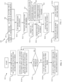
- FIG. 1 is a flowchart depicting an example method 100 for applying TTFields to a region of interest of a subject's body corresponding to a tumor of the subject's body.
- the method 100 includes locating a first pair of transducers and a second pair of transducers on the subject's body (e.g., the first and second pairs of transducers may be located on a first and second pair of locations of the subject's body, respectively).
- the method 100 includes alternately applying, to the region of interest (e.g., tumor) of the subject's body, a first tumor treating electric field (TTField) between the first pair of locations and a second TTField between the second pair of locations.
- the first TTField may be produced by applying a first AC voltage generated between the first pair of locations for a time period, generation of the first TTField is ceased, and then the second TTField is produced by applying a second AC voltage between the second pair of locations for a time period.
- the method 100 includes detecting a change in the region of interest of the subject's body.
- the change in the region of interest may include at least one of a change in the location or a change in volume of the region of interest. Examples of determining a change in region of interest are illustrated in step S216 in FIG. 2 discussed below.
- Detecting the change in the region of interest may include monitoring at least one metric with respect to time and comparing the monitored metric to a baseline pattern of the at least one metric with respect to time established for the subject. A change is detected upon detecting a deviation of the monitored at least one metric from the baseline pattern. Establishing the baseline pattern, monitoring the metric(s), and comparing the metric(s) to the baseline pattern are illustrated in FIGS. 11-16 .
- step S104 If a change in the region of interest is not detected, the method 100 proceeds to step S104. If a change in the region of interest is detected, the method 100 proceeds to step S108, which includes ceasing applying TTFields between the first and second pairs of locations.
- the method 100 comprises selecting a third pair of locations and a fourth pair of locations based on the change in the region of interest determined at step S106.
- the third and fourth pairs of locations are different than the first and second pairs of locations.
- the method 100 may proceed back to step S104 but this time alternately applying, to the region of interest, a third electric field between the third pair of locations of the subject's body and a fourth electric field between the fourth pair of locations of the subject's body.
- the method 100 may continually repeat with each detected change and selected change of locations.
- the first pair of locations and the second pair of locations of the method 100 may correspond to locations of a first part of the first pair of transducers and a first part of the second pair of transducers, and the first TTField may be applied between the first part of the first pair of transducers and the second electric field between the first part of the second pair of transducers.
- the first pair of locations and the second pair of locations of the method 100 may correspond to locations of the entire transducers in each transducer pair.
- Selecting the third and fourth pairs of locations at step S 110 may involve selecting a second part of the first pair of transducers and a second part of the second pair of transducers based on the change in the region of interest determined at step S 106, such that the third electric field is applied between the second part of the first pair of transducers and the fourth electric field is applied between the second part of the second pair of transducers.
- the first part of the two pairs of transducers do not overlap with one another, and the second part of the two pairs of transducers do not overlap with one another.
- the first part of the two pairs of transducers at least partially overlap with one another, and the second part of the two pairs of transducers at least partially overlap with one another.
- Selecting the third and fourth pairs of locations at step S 110 may involve re-locating the first and second pairs of transducers to the third and fourth pairs of locations, respectively, so that the third and fourth electric fields are applied between the first pair of transducers located at the third pair of locations and between the second pair of transducers located at the fourth pair of locations.
- selecting the third and fourth pairs of locations at step S 110 may involve locating a third pair of transducers at the third pair of locations and a fourth pair of transducers at the fourth pair of locations, so that the third and fourth electric fields are applied between the third pair of transducers located at the third pair of locations and between the fourth pair of transducers located at the fourth pair of locations.
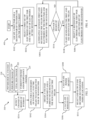
- FIG. 2 is a flowchart depicting an example method 200 for determining a region of interest and locations of transducers on a subject's body for applying TTFields.
- the method 200 includes determining a region of interest of the subject's body corresponding to the tumor (e.g., corresponding to a location and/or volume of the tumor).
- the region of interest in the subject's body may be determined by image data 204 (e.g., via computer simulations built from the image data 204).
- the image data 204 may include one or more images (e.g., X-ray images, magnetic resonance imaging (MRI), computerized tomography (CT) images, ultrasound images, etc.) of a portion of the subject's body.
- images e.g., X-ray images, magnetic resonance imaging (MRI), computerized tomography (CT) images, ultrasound images, etc.
- Determining the region of interest may incorporate posture information 206 of the subject's body.
- Posture information 206 may be detected and/or collected by one or more sensors (e.g., accelerometers, gyroscopes, and/or magnetometers), or determined by user input.
- Sensor(s) may be located external to the first pair of transducers and the second pair of transducers, or may be part of at least one of the first pair of transducers or the second pair of transducers.
- Determining the region of interest may be based on vital signs 208 of the subject's body.
- the vital signs 108 may include respiratory signs (e.g., respiratory rate, respiratory volume).
- Other vital signs may include body temperature, blood pressure, pulse rate, etc.
- Determining the region of interest may be based on electric field measurements 210.
- the electric field measurements 210 may include a voltage measurement and a current measurement generated and/or collected for the TTFields applied for a desirable time period prior to a real-time TTFields treatment, and/or during a real-time TTFields treatment.
- Determining the region of interest may be based on any combination of two or more factors of the image data 204, posture information 206, vital signs 208, and electric field measurements 210. As an example, the determination of the region of interest may be based on image data 204 and posture information 206. In one example, a plurality of regions of interest corresponding to a plurality of postures of the subject are determined. The plurality of regions of interest corresponding to the plurality of postures may be determined prior to real-time TTFields treatment, or may be determined and/or updated during real-time TTFields treatment.
- a first transducer is positioned at a first location and a second transducer is positioned at a second location.
- the locations may be selected based on the determined region of interest at step S202 to yield maximum electric field power delivered to the determined region of interest.
- the method 200 comprises inducing a TTField between the first and second transducers located at the first and second locations.
- the method 200 comprises detecting a change in the region of interest.
- the change in the region of interest may be caused by physiological changes 218 of the subject's body.
- Physiological changes may include at least one of a change in tumor size, change in tumor location, weight gain, weight loss, swelling of the body, swelling in a portion of the body, or inflammation, and may be determined by image data and/or other measurements.
- the change in the region of interest may be caused by a posture change 220.
- the posture change 220 may include a change from one of a plurality of postures to another of the plurality of postures.
- the plurality of postures may include at least two of standing, sitting, lying down, or one or more postures in-between standing, sitting, and lying down.
- the lying down posture may include the subject lying on at least one of the subject's back, left side, right side, or chest.
- Posture changes 220 may be detected and/collected by one or more sensors, or may be entered by user input.
- the change in the region of interest may be caused by a change in vital signs 222 of the subject's body.
- the vital sign change 222 may include a change in respiratory signs (e.g., at least one of respiratory rate or respiratory volume) of the subject, as respiratory rate and respiratory volume may change the internal volume of the torso and lead to a change in the region of interest.
- Other vital signs may include, for example, body temperature, blood pressure, and pulse rate.
- Vital sign changes 222 may be detected by sensors, or entered by user input.
- the change in the region of interest may be determined based on a detected change in one or more of the factors 218-222 listed above. Additionally, or alternatively, the change in the region of interest may be determined based on a change (224) in the voltage and/or current of TTFields applied to the region of interest, a resistivity of the subject's body, and/or an impedance of the subject's body.
- Current measurements are indicative of a current of the TTFields passing through the subject's body between a pair of transducers, as measured at one or more electrodes in the pair of transducers.
- Voltage measurements are indicative of a voltage applied to the selected pair of transducers to induce the TTFields.
- a resistivity of the subject's body along a path of the TTField may be calculated based on the voltage and current measurements as discussed below. Further, the voltage and current measurements and/or calculated resistivity may be used to calculate an impedance of the subject's body.
- the resistivity calculated for one channel e.g., between a pair of transducers
- the resistivity calculated for one channel may be divided by the distance between the pair of transducers to determine an impedance of the subject's body between the pair of transducers. This calculation may be repeated for both channels used to apply alternating TTFields to the region of interest.
- the method 200 includes optionally generating a habit model for the subject based on the data collected at steps S202 and S216.
- the posture information 206, vital signs 208, posture change 220, vital sign change 222, and current/voltage change 224 may be collected and recorded over time during the TTFields treatment and stored with a time stamp.
- a habit model for the subject may be generated by a machine based on the collected and stored data, with or without additional user input.
- the habit model may include information regarding time stamp, posture information, and region of interest and may be presented at an output device.
- a habit model may include the following exemplary information:
- the method 200 may include generating one or more recommendations based on the change in the region of interest obtained at step S216 and/or the habit model generated at step S226. This is similar to step S310 in FIG. 3 .
- the recommendations may be for locations on the subject's body at which to place transducers and/or recommended parts of the transducers for applying TTFields. Recommendations may be incorporated in the habit model.
- the method 200 may include adjusting the applied electric field based on the change in the region of interest detected in step S216 and/or the habit model generated at step S226.
- the adjustment of the electric fields may include adjusting the location of the transducers and/or adjusting the voltage of the TTFields applied to the subject's body.
- the adjustments may be automatic.
- the method 200 may change from part 1 to part 2 of the transducers for applying the electric field at a time when the subject changes posture according to the habit model.
- inquiries for confirmation may be presented to the subject on a user device to confirm the change of postures before the TTFields are adjusted.
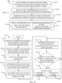
- FIG. 3 is a flowchart depicting another example method 300 for determining locations of transducers on a subject's body for applying TTFields.
- the method 300 includes performing step S216 of FIG. 2 .
- the method 300 includes generating a plurality of regions of interest based on the obtained changes in the region of interest in step S216. This may involve determining a plurality of postures of the subject's body.
- the step S302 may further comprise selecting a pair of transducers for each region of interest (e.g., for each posture) and applying TTFields to each selected pair of transducers.
- Step S304 for each region of interest (e.g., for each posture), the method 300 includes receiving a voltage measurement and a current measurement associated with the TTFields induced between the first and the second transducers of the selected pair of transducers.
- Step S304 may be a computer-implemented step in which current and voltage measurements that were obtained and/or recorded are received at a processing component of a computer.
- the current and voltage measurements may be generated and/or collected (e.g., received or accessed from a log file) prior to a real-time treatment of TTFields, or in real-time or near real-time during a treatment period in which TTFields are applied. Such voltage and current measurements may be obtained at regular intervals throughout TTFields treatment.
- the method 300 includes calculating a resistivity of the subject's body along a path of the TTField between the first transducer and the second transducer based on the received current and voltage measurements.
- the calculated resistivity may change over time in which TTFields are applied to the subject's body. Resistivity changes may be the result of, e.g., physiological changes 218, posture changes 220, vital sign changes 222, or changes in placement / attachment of transducers.
- the method 300 includes calculating a power density of the TTFields between the first transducer and the second transducer based on the received current and voltage measurements.
- the power density of the TTFields may be used to represent the TTFields dose delivered to the corresponding region of interest.
- the power density P may be calculated by Equations 1-3 based on voltage and current measurements of the applied TTFields.
- the method 300 includes selecting and outputting one or more recommended pairs of transducers based on the calculated resistivity and/or the calculated power density.
- the selection one or more recommended pairs of transducers is based on the calculated resistivity for each region of interest at step S306.
- Step S310 may include comparing the calculated resistivities for the plurality of pairs of transducers for each region of interest and, for each region of interest, ranking the plurality of pairs of transducers based on the calculated resistivities. The recommended transducer pairs may be selected based on the ranking.
- Step S310 may include, for each region of interest, selecting a first pair of transducers based on the ranking of the plurality pairs of transducers, and, for each region of interest, selecting a second pair of transducers from the remaining one or more pairs of transducers based on the ranking.
- the selection of the second pair of transducers is based on the selection of the first pair of transducers (e.g., based on an intersection angle with regards to the selected first pair of transducers).
- the second pair of transducers may be selected such that a first angle between a first line defined by the first part of the first pair of transducers and a second line defined by the first part of the second pair of transducers is approximately 90 degrees +/- 20 degrees; and a second angle between a third line defined by the second part of the first pair of transducers and a fourth line defined by the second part of the second pair of transducers is approximately 90 degrees +/- 20 degrees.
- Step S310 may include calculating a local minimum power density (LMiPD) for a combination of two pairs of transducers in the plurality pairs of transducers and selecting the layout with a maximum LMiPD.
- LMiPD represents the lower of two power densities delivered by the TTFields to the region of interest via two pairs of transducers, calculated via Equation.
- FIG. 4 is a flowchart depicting another example method 400 for determining the locations of transducers on a subject's body.
- method 400 includes performing steps S102, S106, and S108 of FIG. 1 .
- the method 400 includes selecting a first set of electrodes of the first pair of transducers and a first set of electrodes of the second pair of transducers.
- Each transducer may include an array of electrode elements.
- the electrodes may be individually addressable electrodes, as discussed further below. The selection of these sets of electrodes may be based on the region of interest of the subject's body.
- the method 400 includes alternately applying to the region of interest a first TTField between a first set of electrodes of the first pair of transducers and a second TTField between a first set of electrodes of the second pair of transducers. This is similar to step S104 in FIG. 1 .
- the method 400 includes selecting a second set of electrodes of the first pair of transducers and a second set of electrodes of the second pair of transducers based on the change in region of interest determined at step S106.
- the selection of the second sets of electrodes of the first pair and second pair of transducers is based on the change in region of interest.
- a third TTField and a fourth TTField may then be alternately applied to the region of interest between the second set of electrodes of the first pair of transducers and between the second set of electrodes of the second pair of transducers.
- the first set of electrodes and the second set of electrodes of the first pair of transducers may not overlap with one another, or the first set of electrodes and the second set of electrodes of the first pair of transducers may partially overlap with one another.
- At least one electrode of the first pair of transducers may emit different amounts of non-zero energy during the first and third electric fields
- at least one electrode of the second pair of transducers may emit different amounts of non-zero energy during the second and fourth electric fields.
- the at least one electrode in both the first set and the second set of electrodes e.g., a first electrode
- the energy emitted by the first electrode during the first electric field may be different than the energy emitted by the first electrode during the third electric field.
- the energy emitted by the first electrode during the first electric field may be a percentage of the energy emitted by the first electrode during the third electric field, the percentage being greater than 0% and less than 100%, or the energy emitted by the first electrode during the third electric field may be a percentage of the energy emitted by the first electrode during the first electric field, the percentage being greater than 0% and less than 100%.
- the first electrode emits energy during a first portion in a period of the first electric field and during a first portion in a period of the third electric field. The energy emitted during the first portion in the period of the first electric field may be different than the energy emitted during the first portion in the period of the third electric field.
- the different energy emitted by the first electrode during the first electric field and the third electric field is due to the voltage signal applied to the first electrode being different during the first and third electric field.
- the first electrode receives different voltage signals for the first and third electric fields.
- the first electrode may receive a first non-zero voltage during the first electric field and a second non-zero voltage during the third electric field, the first non-zero voltage different from the second non-zero voltage.
- the first electrode receives a same amplitude of voltage during the first and third electric fields but during different time segments of periods of the first and third electric fields.
- the different energy emitted by the first electrode during the first electric field and the third electric field is due to a capacitance change of the first electrode.
- the first electrode has a first capacitance during the first electric field and has a second capacitance during the third electric field.
- the first electrode may receive the same voltage signal during the first and third electric fields. Examples of structures in which different energy may be emitted by a first electrode are discussed below with reference to FIG. 8 .
- FIGS. 5A-6B depict examples of determining locations of transducers based on the region of interest for two pairs of transducers to be located. The selection of locations may be based on a plurality of regions of interest associated with a plurality of postures. In FIGS. 5A and 5B , a plurality of locations is selected on a torso of the subject's body. First, second, third, and fourth locations 501, 502, 503, and 504 are selected to locate transducers when the subject is lying on the left side, and fifth, sixth, seventh, and eighth locations 505, 506, 507, and 508 are selected to locate transducers when the subject is standing.
- Locations 501 and 504 may form a first pair of locations for a first pair of transducers, and locations 502 and 503 may form a second pair of locations for a second pair of transducers.
- Locations 505 and 508 may form the first pair of locations to locate the first pair (or a third pair) of transducers, and locations 506 and 507 may form the second pair of locations to locate the second pair (or a fourth pair) of transducers.
- a plurality of electrode elements is integrated in one transducer array 609.
- the transducer array may be integrated into a helmet or a garment (e.g., hat, shirt, or pants). Multiple pairs of transducers may be selected in the transducer array 609, each transducer having a plurality of electrode elements selected from the transducer array 609.
- First, second, third, and fourth transducers 601, 602, 603, and 604 are selected in the transducer array 609 when the subject is lying on the left side, and fifth, sixth, seventh, and eighth transducers 605, 606, 607, and 608 are selected when the subject is standing.
- Transducers 601 and 603 (or transducers 605 and 607) may form the first pair of transducers, and transducers 602 and 604 (or transducers 606 and 608) may form the second pair of transducers.
- FIG. 7 depicts an example transducer with individually selectable electrodes.
- a first set of electrode elements 804 may be selected based on the region of interest, and a second set of electrode elements 809 may be selected based on a change in the region of interest.
- the first set 804 includes electrode elements 805, 806, 807, and 808, and the second set 809 includes electrode elements 807, 808, 810, and 811. Electrode elements 807 and 808 are in both sets.
- FIG. 8 depicts an example configuration of a transducer.
- the transducer 912 includes n electrodes, e.g., 906 and 909, and the electrodes 906 and 909 are wired to switches 902/903/904/905 controlled by a controller 901.
- Each electrode includes two electrode elements.
- Electrode 906 includes electrode elements 907 and 908 and electrode 909 includes electrode elements 910 and 911.
- a controller 901 may selectively turn off some switches connected to the electrodes to change the voltage signal applied to the electrodes 906 and 909 and/or to change a capacitance of the electrodes 906 and 909. Examples of the transducer are described in U.S. Patent Application Publication No. 2020/0155835 A1 .
- FIG. 9 depicts an example configuration of a pair of transducers 1001 and 1002.
- Both transducers 1001/1002 may include electrode elements 1003/1005 positioned on a substrate 1004/1006 and electrically and mechanically connected through conductive wiring 1009/1010.
- the substrate(s) 1004/1006 may include cloth, foam, flexible plastic, and/or conductive medical gel.
- one or more transducers may include electrode elements that are electrically and mechanically connected without a substrate. Transducers may be affixed to the subject's body or attached/incorporated in garment(s) covering the subject's body.
- the transducers 1001 and 1002 may be connected to an AC voltage generator 1007 and a controller 1008, which may include a computer having one or more processors 1013 and memory 1014.
- the memory 1014 may store instructions that when executed by the one or more processors control the AC voltage generator 1007 to induce an electric field between the transducers 1001 and 1002 and/or cause the computer to perform one or more methods disclosed herein.
- the controller 1008 may monitor operations performed by the voltage generator 1007 and store current/voltage values in memory 1014. Other types of information (e.g., temperature values, posture information, vital signs, etc.) may be collected as well (e.g., via sensors 1016). Various types of information may be stored in a log file, which may be in the memory 1014.
- FIG. 10 depicts an exemplary apparatus 1100 to determine locations of transducers for applying TTFields according to various embodiments herein.
- the apparatus 1100 includes one or more processors 1102, a memory 1103, and one or more output devices 1105.
- the apparatus 1100 may be a computer.
- the apparatus 1100 may be incorporated into, or separate from and communicatively coupled to, the controller 1008 of FIG. 9 .
- the memory 1103 is accessible by the one or more processors 1102, and the memory 1103 stores instructions that, when executed by the processor(s) 1102, cause the apparatus 1100 to perform one or more methods disclosed herein.
- the processor(s) 1102 may generate and/or rank a plurality of locations for the transducers, and output one or more location recommendations to a user on the output device(s) 1105, or output an alert.
- the one or more inputs 1101 may include image data, current and voltage measurements, posture information, vital signs, physiological information, and/or user inputs.
- FIG. 11 is a flowchart describing an example computer-implemented method 1200 of detecting and responding to a change in a subject's body while or after TTFields are induced in the subject's body.
- the method 1200 includes receiving one or more measurements. These may include measurement(s) associated with one or more TTFields induced in the subject's body.
- the step S1202 may comprise receiving current and voltage measurements associated with one or more TTFields induced between at least part of a first transducer located at a first location of the subject's body and at least part of a second transducer located at a second location of the subject's body.
- the one or more measurements may include measurement(s) associated with the subject's body while the one or more TTFields are induced in the subject's body.
- the measurement(s) may comprise a temperature associated with the subject's body while TTFields are induced in the subject's body.
- Other measurements may include those used to determine posture or vital signs of the subject's body.
- the measurements received at step S 1202 may be collected in real-time or near real-time while TTFields are applied.
- the AC generator monitors a current and voltage of the AC voltage applied to the pair of transducers and records the current and voltage measurements, for example, in a log file.
- one or more sensors separate from the AC generator are used to detect the current and voltage of the TTFields and generate current and voltage measurements for recording in a log file.
- voltage, current, temperature, and/or other measurements may be collected during a treatment session of inducing TTFields in the subject's body. For example, voltage, current, temperature, and/or other measurements may be obtained at regular intervals (e.g., every second, five seconds, thirty seconds, minute, five minutes, ten minutes, thirty minutes, hour, two hours, four hours, or some other interval) throughout TTFields treatments.
- the method 1200 may include receiving an initial data set of at least one metric with respect to time.
- the at least one metric includes a measurement associated with one or more tumor treating fields induced in the subject's body or associated with the subject's body while one or more tumor treating fields are induced in the subject's body.
- the initial data set may be a collection of measurement values for at least one metric stored with a time stamp.
- the at least one metric may comprise one or more measurements selected from the group consisting of: a resistivity associated with one or more TTFields induced in the subject's body, a current associated with one or more TTFields induced in the subject's body, a voltage associated with one or more TTFields induced in the subject's body, a differential resistivity between alternating TTFields induced in the subject's body between two pairs of transducer arrays, a sum of resistivities between alternating TTFields induced in the subject's body between two pairs of transducer arrays, an impedance associated with one or more tumor treating fields induced in the subject's body, and a temperature of the subject's body.
- Other metrics may be received in other embodiments.
- Step S1204 may include calculating values of at least one metric (e.g., resistivity, differential resistivity, or resistivity sum) from measurements that were collected or received at step S1202 and associated with corresponding time values.
- the step S1204 may comprise calculating a resistivity of the subject's body along a path of a TTField between at least part of the first transducer and at least part of the second transducer based on current and voltage measurements received at step S1202 according to Equation 1.
- the step S1204 may comprise calculating an impedance associated with one or more TTFields induced in the subject's body, using the calculation techniques discussed above.
- Step S1204 may comprise calculating a set of differential resistivities with respect to time from measurements that were collected or received at step S1202.
- the differential resistivity metric may be a difference between a first resistivity associated with a first TTField induced between at least part of a first pair of transducer arrays at a first pair of locations of the subject's body and a second resistivity associated with a second TTField induced between at least part of a second pair of transducer arrays at a second pair of locations of the subject's body.
- Calculating a differential resistivity may comprise calculating an absolute value of a difference between first and second calculated resistivities for each time in the initial data set.
- Step S1204 may comprise calculating a set of resistivity sums, which involves calculating a sum of first and second calculated resistivities for each time in the initial data set.
- the method 1200 comprises determining a baseline pattern of the at least one metric with respect to time based on the initial data set.
- the initial data set is indicative of the at least one metric collected during a training period.
- collected may refer to the metric(s) either measured (e.g., via sensors) or calculated based on measurements.
- the "training period” may refer to a period of time during which the at least one metric is collected.
- the baseline pattern may comprise a signature in the initial data set that is specific to the subject, representing a cycle related to the subject's unique physiology.
- the baseline pattern may capture time-dependent changes in the subject's body, such as physiological changes (e.g., sweating, hair growth, etc.), changes based on circadian rhythm (e.g., temperature, hormonal, or other changes in a 24 hour cycle), and/or changes in the subject's activities, postures, habits, vital signs, and/or locations (e.g., sleeping, sports, walking, exercising, or sitting at a desk).
- the baseline pattern may be a range of values of the at least one metric averaged over a time window or the rate of change of the at least one metric averaged over the time window.
- a time window average of one or more metrics e.g., calculated impedance
- the rate of change of one or more metrics may be calculated and monitored via comparison of the value of the metric to one or more thresholds. Changes in these time window averages may be correlated with changes in the size of the tumor ( FIGS. 17A-17F ).
- determining the baseline pattern may comprise applying one or more numerical analyses to the initial data set, such as performing a principal component analysis (PCA) on the initial data set.
- PCA principal component analysis
- Principal components may be computed directly by a computer using the initial data set.
- S(t) is the baseline pattern with respect to time
- v 1 (t), v 2 (t), and v 3 (t) are eigenvectors representing the principal components determined for the initial data set
- a 1 , a 2 , and a 3 are eigenvalues representing amplitudes for their associated eigenvectors.
- Each eigenvector v n (t) may be related to physiological conditions in the subject's body, while the corresponding eigenvalue a n may be related to the strength or impact of that physiological condition on the data.
- the method comprises monitoring the at least one metric with respect to time following the training period (e.g., during later TTFields treatment).
- the training period may be a period of multiple days during which one or more TTFields treatments are performed on the subject's body.
- Monitoring the at least one metric may involve receiving and/or calculating the at least one metric, similar to step S 1204.
- monitoring the at least one metric with respect to time may be performed in real-time or near real-time during a time period in which TTFields are induced in the subject's body.
- Monitoring the at least one metric associated with the TTFields or the subject's body after the training period may include receiving or accessing a log file, which may occur after application of a TTFields treatment is complete.
- the method may comprise determining whether the monitored at least one metric (e.g., in new data sets) deviates from the predetermined baseline pattern.
- the method 1200 includes triggering an event in response to detecting (at step S1210) a deviation of the monitored at least one metric from the baseline pattern.
- the triggered event may include selecting a recommendation for adjusting location(s) of the subject's body for placement of one or more transducers based on the detected deviation. This may involve one or more of the methods discussed above with reference to FIGS. 1-4 .
- the triggered event may include outputting an alert.
- outputting the alert may include outputting an alert 1218 indicating that additional imaging of the subject's body is needed.
- outputting the alert may include outputting an alert 1220 indicating a change in a tumor of the subject's body.
- the process may repeat steps S1208 and S1210 until the monitored metric(s) deviate from the baseline pattern triggering an event at S1212.
- the process of method 1200 may begin again from step S1202 to determine a new baseline pattern based on at least one metric collected and/or calculated during a new training period, 1) if additional imaging performed on the subject indicates no change in the tumor, or 2) if transducer pairs are positioned at new locations.
- FIG. 12 is a flowchart describing an example computer-implemented method 1300 of tracking physiological changes of a subject's body by detecting a deviation of a monitored metric from a baseline.
- FIG. 12 is an example process of performing steps S1206, S1208, and S1210 of FIG. 11 .
- Steps S1206 and S1208 in FIG. 11 may comprise steps S1302 and S1304 of FIG. 12 , respectively.
- Step S1210 of FIG. 11 may comprise steps S1306, S1308, and/or S1310 of FIG. 12 .
- the initial data set received at step S104 of FIG. 1 is decomposed using PCA.
- the method 1300 may include collecting one or more additional data sets of the at least one metric with respect to time.
- the method 1300 may include decomposing the one or more additional data sets of the at least one metric using, for example, the same PCA decomposition that was used on the initial data set or an altered PCA.
- the method 1300 may include comparing the one or more additional data sets to the PCA decomposition of the initial data of S 1302.
- the method 1300 may include detecting a deviation of one or more additional data sets from the baseline pattern.
- the comparison at S1308 may involve comparing a decomposition (S1306) of the one or more additional data sets to the PCA decomposition (S1302) of the initial data set.
- S'(t) is the PCA decomposition of the second data set with respect to time;
- v' 1 (t), v' 2 (t), and v' 3 (t) are eigenvectors representing the principal components determined for the second data set; and a' 1 , a' 2 , and a' 3 are eigenvalues representing amplitudes for the associated eigenvectors.
- the comparison at S1308 may comprise comparing eigenvectors extracted from the second data set to those extracted from the initial data set (e.g., comparing v i (t) to v' i (t) ).
- the method 1300 may comprise detecting a deviation of the second data set from the baseline pattern in response to detecting a new eigenvector v' i (t) (1312) that is not present in the PCA decomposition of the initial data set.
- the PCA decomposition (baseline pattern) of the initial data set may output a set of three eigenvectors v 1 (t), v 2 (t), and v 3 (t), while the PCA decomposition of the second data set may output a set of four eigenvectors v' 1 (t), v' 2 (t), v' 3 (t), and v' 4 (t).
- the number of eigenvectors (or principal components) extracted from each decomposition may be determined based on the relative impact of each principal component determined by the PCA software.
- the step S1306 may comprise decomposing one or more additional data sets via PCA into the same eigenvectors v 1 (t), v 2 (t), and v 3 (t) that were extracted from the PCA (S1302) of the initial data set.
- the computer may detect an emergence of a new eigenvector during the decomposition. If an eigenvector emerges after a certain time without a corresponding change in the subject's habits, this may indicate a change at the tumor level.
- the step S1306 may comprise decomposing a second data set into a second set of eigenvalues corresponding to the same set of eigenvectors extracted from the PCA of the initial data set.
- S'(t) is the PCA decomposition of the second data set with respect to time;
- v 1 (t), v 2 (t), and v 3 (t) are eigenvectors representing the principal components determined for the initial data set; and
- a' 1 , a' 2 , and a' 3 are eigenvalues representing amplitudes for these associated eigenvectors based on the decomposition of the second data set.
- the second data set is decomposed into the same eigenvectors that were identified during PCA of the initial data, and eigenvalues are determined for each of those eigenvectors to most closely fit the second data set.
- the eigenvalues extracted from the second data set may be compared (S1308) to those extracted from the initial data set (e.g., comparing a i to a' i ).
- the method 1300 may comprise detecting a deviation of the second data set from the baseline pattern in response to detecting an eigenvalue in the second set of eigenvalues a' i that crosses a threshold (1314) based on the first set of eigenvalues a i .
- the PCA decomposition of the second data set may output one or more eigenvalues a' 1 , a' 2 , and a' 3 that differ from the corresponding eigenvalues ( a 1 , a 2 , and a 3 ) for the initial data set by a certain threshold amount or by a certain threshold percentage.
- the comparison at S1308 may comprise comparing multiple sets of eigenvalues extracted via PCA of multiple sequential data sets to each other and to the eigenvalues extracted from the initial data set.
- the method 1300 may comprise collecting multiple data sets of the at least one metric over time and decomposing each of the multiple data sets into another set of eigenvalues corresponding to the same set of eigenvectors extracted from the PCA of the initial data set.
- the method 1300 may comprise detecting a deviation of the multiple data sets from the baseline pattern in response to detecting a trend (1316) in the generated eigenvalue a' i of the multiple data sets corresponding to the same eigenvector of the initial data set.
- the comparison at S1308 may involve comparing a signal representing the monitored at least one metric with respect to time to the PCA decomposition (S1302) of the initial data set.
- the comparison at S1308 may include generating an initial signal representative of at least one metric with respect to time based on the first set of eigenvectors and first set of eigenvalues from the PCA of the initial data set (S1302), and then calculating a difference between this "initial signal" and the corresponding signal of the monitored at least one metric.
- the "initial signal” may be generated by solving a system of equations using the PCA decomposition of the initial data set (1302) to estimate a signal (the "initial signal") of a metric M taken with respect to time t for the additional data set.
- the method 1300 may comprise detecting a deviation in response to detecting that the difference between the initial signal and the corresponding signal of the metric exceeds a threshold (1318).
- decomposition of additional data sets and comparison of the data sets to the initial data set may be carried out sequentially for each new data set in real-time or near real-time during TTFields treatments. If no deviation is detected at S1310, then steps S1304-S1308 repeat.
- FIG. 13 depicts a plot 1400 of an example baseline pattern 1402 of a metric 1404 with respect to time 1406.
- the baseline pattern 1402 may represent a 24-hour cycle of the metric 1404.
- one or more additional metrics may be monitored at the same time to determine an overall baseline pattern for the subject.
- the PCA of the initial data set may track a recognizable 24-hour pattern.
- FIG. 14 depicts a computer-implemented method 1500 for calibrating a system for detecting changes in a subject's body while or after TTFields are induced in the subject's body, which may be performed during the training period.
- the method 1500 may include outputting a first location at which to locate a first transducer on the subject's body and a second location at which to locate a second transducer on the subject's body. The first location and second location may be output to a user interface.
- Step S1502 may further include outputting third and fourth locations at which to locate third and fourth transducers on the subject's body.
- the method 1500 includes receiving one or more measurements associated with one or more TTFields induced in the subject's body or associated with the subject's body while the one or more TTFields are induced in the subject's body.
- receiving (S1504) the one or more measurements associated with one or more TTFields induced in the subject's body may comprise receiving one or more measurements associated with a first electric field induced between a first pair of transducers located at a first location and a second location on the subject's body and receiving one or more measurements associated with a second electric field induced between a second pair of transducers located at a third location and a fourth location on the subject's body.
- the method 1500 includes determining an initial data set of at least one metric with respect to time based on the one or more measurements received during the training period, as discussed above.
- the method 1500 includes performing a PCA on the initial data set to generate a first set of eigenvectors and a first set of eigenvalues.
- the method 1500 includes determining a baseline pattern of the at least one metric with respect to time, the baseline pattern comprising at least a portion of the first set of eigenvectors and the first set of eigenvalues.
- the baseline pattern may include a subset of the total number of eigenvectors in the first set of eigenvectors and a corresponding subset of the first set of eigenvalues generated via PCA.
- the method 1500 includes storing the baseline pattern in a memory.
- FIG. 15 depicts an example method 1600 for correcting for differences in transducer positioning during the process of FIG. 14 , as the transducers may be removed and replaced on the subject's body periodically.
- the method 1600 includes outputting a first location to locate a first transducer on the subject's body and a second location to locate a second transducer on the subject's body.
- the method 1600 may include receiving input (e.g., image or video data) corresponding to an actual location of the first transducer on the subject's body and an actual location of the second transducer on the subject's body.
- the method 1600 may include comparing the actual location of the first transducer with the first location at which the transducer is to be placed, and comparing the actual location of the second transducer with the second location at which the transducer is to be placed.
- the method 1600 may include correcting for any difference detected between the actual positioning of transducers and the desired first and second locations.
- the correction at S1608 may involve adjusting (1610) one or more measurements (e.g., those received at S 1504) to correct for at least one of: a difference in positioning between the actual location of the first transducer and the first location, or a difference in positioning between the actual location of the second transducer and the second location.
- the correction at S1608 may involve outputting, to a user interface, instructions for correcting a positioning (1612) of at least one of the first transducer or the second transducer.
- FIG. 16 depicts an example computer-implemented method to detect a change in a subject's body while or after TTFields are induced.
- the method 1700 includes, at step S1702, receiving current and voltage measurements associated with a first electric field induced in the subject's body, the first electric field passing through a tumor in the subject's body.
- the method 1700 includes, at step S1704, receiving current and voltage measurements associated with a second electric field induced in the subject's body, the second electric field passing through the tumor in the subject's body.
- the method 1700 includes, at step S1706, calculating a differential resistivity calculated based on the received current and voltage measurements associated with the first and second electric fields.
- the differential resistivity includes a difference between a first resistivity of the subject's body along a path of the first electric field and a second resistivity of the subject's body along a path of the second electric field.
- the method 1700 includes, at step S1708, determining an initial data set of at least one metric with respect to time, the at least one metric including at least the differential resistivity of S1706.
- the initial data set is determined based on measurements collected during a training period.
- the method 1700 includes, at step S1710, determining a baseline pattern of the at least one metric with respect to time based on the initial data set of S1708.
- the method 1700 includes, at step S1712, determining one or more additional data sets of the at least one metric with respect to time based on measurements collected following the training period.
- the method 1700 may include, at step S1714, determining whether the at least one metric associated with the one or more additional data sets deviates from the baseline pattern of S1710. If no deviation is detected, the method 1700 proceeds back to S1712. If a deviation of the additional data sets from the baseline pattern is detected, the method 1700 proceeds to step S1716, which includes outputting an alert in response to detecting a deviation of the at least one metric in the one or more additional data sets from the baseline pattern.
- Step S1716 may include outputting an indication 1718 that additional imaging of the subject's body is needed, outputting an indication 1720 of a change in a tumor of the subject's body, or a combination thereof.
- FIGS 17A-17F depict examples of relationships between calculated impedance measurements taken throughout TTFields treatment and tumor size determined via image data.
- Each of FIGS. 17A-17F provides a plot 1800 (i.e., 1800A, 1800B, 1800C, 1800D, 1800E, and 1800F) showing trend lines of calculated impedance 1802 (i.e., 1802A, 1802B, 1802C, 1802D, 1802E, and 1802F) with respect to time and of a determined tumor size 1804 (i.e., 1804A, 1804B, 1804C, 1804D, 1804E, and 1804F) with respect to time.
- Each plot 1800 corresponds to actual measurements / determinations made for one of six patients during clinical trials.
- the impedance 1802 is a sum total of the impedance between two channels delivering TTFields (e.g., a first channel between a first pair of transducers and a second channel between a second pair of transducers).
- the tumor size 1804 is an estimation of tumor volume calculated based on MRI images from the patients.
- the trend line for tumor size 1804 is shown via straight lines connecting multiple tumor size values at different times (corresponding to MRIs taken at distinct points during TTFields treatment).
- the trend line for impedance 1802 provides average impedance values taken via window averaging of the impedance over a period of 15 days.
- the measurement shown for each day is an average of impedance values at the current day, the prior 7 days, and the following 7 days. Times where no impedance values are shown correspond to times in which the transducers were not used or there was no access to the log files.
- the calculated impedance 1802 is correlated to the determined tumor size 1804.
- impedance measurements can be used to track tumor progression. Changes in impedance values may be used to track changes in the region of interest (e.g., tumor) over time without needing to take an MRI. Calculating and tracking the impedance may be used to 1) determine when a next MRI should be taken, 2) select new pairs of locations for placement of transducers, or both.
- current and voltage measurements associated with tumor treating fields induced in the subject's body may be received and then used to calculate an impedance associated with the subject's body; the impedance may be monitored with respect to time while TTFields are induced in the subject's body; and upon detecting a deviation of the monitored impedance from a baseline (e.g., impedance values and/or rate of change thereof), an event may be triggered.
- a baseline e.g., impedance values and/or rate of change thereof
Landscapes
- Health & Medical Sciences (AREA)
- Animal Behavior & Ethology (AREA)
- Public Health (AREA)
- Engineering & Computer Science (AREA)
- Biomedical Technology (AREA)
- Nuclear Medicine, Radiotherapy & Molecular Imaging (AREA)
- Radiology & Medical Imaging (AREA)
- Veterinary Medicine (AREA)
- Life Sciences & Earth Sciences (AREA)
- General Health & Medical Sciences (AREA)
- Hospice & Palliative Care (AREA)
- Oncology (AREA)
- Measurement And Recording Of Electrical Phenomena And Electrical Characteristics Of The Living Body (AREA)
- Apparatus For Radiation Diagnosis (AREA)
- Measuring And Recording Apparatus For Diagnosis (AREA)
- Measurement Of The Respiration, Hearing Ability, Form, And Blood Characteristics Of Living Organisms (AREA)
- Electrotherapy Devices (AREA)
Claims (6)
- Einrichtung zur Erkennung und Reaktion auf Veränderungen in einem Subjekt beim Anlegen von Tumorbehandlungsfeldern auf einen Bereich von Interesse des Körpers des Subjekts entsprechend einem Tumor des Körpers des Subjekts, wobei die Einrichtung einen oder mehrere Prozessoren (1102) und Speicher (1103) umfasst, der für den einen oder die mehreren Prozessoren (1102) zugänglich ist und gespeicherte Anweisungen bereitstellt, die, wenn sie von dem einen oder den mehreren Prozessoren (1102) ausgeführt werden, die Einrichtung veranlassen:auf den Bereich von Interesse abwechselnd ein erstes elektrisches Feld zwischen einem ersten Paar von Stellen (501, 504) des Körpers des Subjekts und ein zweites elektrisches Feld zwischen einem zweiten Paar von Stellen (502, 503) des Körpers des Subjekts anzulegen;eine Veränderung in dem Bereich von Interesse zu erkennen;Veränderungen in dem Bereich von Interesse auf der Grundlage zumindest eines von einer Stellungsveränderung des Körpers des Subjekts, einer Veränderung in den Vitalzeichen des Körpers des Subjekts, einer physiologischen Veränderung des Körpers des Subjekts, einer Veränderung in der Spannung und/oder dem Strom der Tumorbehandlungsfelder oder einer Veränderung in der Impedanz des Körpers des Subjekts über die Zeit aufzuzeichnen;ein Gewohnheitsmodell des Körpers des Subjekts auf der Grundlage der aufgezeichneten Veränderungen in dem Bereich von Interesse zu erzeugen;das Anlegen der ersten und zweiten elektrischen Felder auszusetzen;auf Grundlage des Gewohnheitsmodells ein drittes Paar von Stellen (505, 508) des Körpers des Subjekts und ein viertes Paar von Stellen (506, 507) des Körpers des Subjekts auszuwählen, wobei das dritte und vierte Paar von Stellen (505, 508; 506, 507) sich von dem ersten und zweiten Paar von Stellen (501, 504; 502, 503) unterscheiden; undauf den Bereich von Interesse abwechselnd ein drittes elektrisches Feld zwischen dem dritten Paar von Stellen (505, 508) und ein viertes elektrisches Feld zwischen dem vierten Paar von Stellen (506, 507) anzulegen.
- Einrichtung nach Anspruch 1, wobei die Veränderung in dem Bereich von Interesse zumindest eine von einer Veränderung in einer Stelle von Interesse oder eine Veränderung in einem Volumen von Interesse beinhaltet.
- Einrichtung nach Anspruch 1, wobei die gespeicherten Veränderungen bei der Erkennung der Veränderung in dem Bereich von Interesse die Einrichtung dazu veranlassen:zumindest eine Messgröße in Bezug auf die Zeit zu überwachen, wobei die zumindest eine Messgröße eine Messung beinhaltet, die einem oder mehreren Tumorbehandlungsfeldern, die in dem Körpers des Subjekts induziert werden, zugeordnet sind oder dem Körpers des Subjekts zugeordnet sind; unddie zumindest eine überwachte Messgröße mit einem Basislinien-Muster der zumindest einen überwachten Messgröße in Bezug auf die Zeit, die für das Subjekt festgelegt wurde, zu vergleichen; undeine Abweichung der zumindest einen überwachten Messgröße von dem Basislinien-Muster zu erkennen.
- Einrichtung nach Anspruch 1, wobei das erste elektrische Feld zwischen einem ersten Teil eines ersten Paars von Messwandlern entsprechend dem ersten Paar von Stellen (501, 504) angelegt wird, das zweite elektrische Feld zwischen einem ersten Teil eines zweiten Paars von Messwandlern entsprechend dem zweiten Paar von Stellen (502, 503) angelegt wird, das dritte elektrische Feld zwischen einem zweiten Teil des ersten Paars von Messwandlern entsprechend dem dritten Paar von Stellen (505, 508) angelegt wird, und das vierte elektrische Feld zwischen einem zweiten Teil des zweiten Paars von Messwandlern entsprechend dem vierten Paar von Stellen (506, 507) angelegt wird.
- Einrichtung nach Anspruch 1, wobei das erste elektrische Feld zwischen einem ersten Paar von Messwandlern angelegt wird, das sich an dem ersten Paar von Stellen (501, 504) befindet, das zweite elektrische Feld zwischen einem zweiten Paar von Messwandlern angelegt wird, das sich an an einem zweiten Paar von Stellen (502, 503) befindet, und das dritte und vierte elektrische Feld entweder zwischen dem ersten Paar von Messwandlern, das sich an dem dritten Paar von Stellen (505, 508) befindet, und dem zweiten Paar von Messwandlern, das sich an dem vierten Paar von Stellen (506, 507) befindet, oder zwischen einem dritten Paar von Messwandlern, das sich an dem dritten Paar von Stellen (505, 508) befindet und einem vierten Paar von Messwandlern, das sich an dem vierten Paar von Stellen (506, 507) befindet, angelegt wird.
- Einrichtung nach Anspruch 1, wobei das Auswählen des dritten und vierten Paars von Stellen (505, 508; 506, 507) und das Anlegen des dritten und vierten elektrischen Felds automatisch erfolgen.
Priority Applications (1)
| Application Number | Priority Date | Filing Date | Title |
|---|---|---|---|
| EP25154063.9A EP4520392A3 (de) | 2021-03-23 | 2022-03-23 | Vorrichtung zur erkennung und reaktion auf änderungen bei personen |
Applications Claiming Priority (5)
| Application Number | Priority Date | Filing Date | Title |
|---|---|---|---|
| US202163164957P | 2021-03-23 | 2021-03-23 | |
| US202163168059P | 2021-03-30 | 2021-03-30 | |
| US202163196528P | 2021-06-03 | 2021-06-03 | |
| US17/701,470 US20220305277A1 (en) | 2021-03-23 | 2022-03-22 | Methods and apparatuses for detecting and responding to changes in a subject |
| PCT/IB2022/052655 WO2022201060A1 (en) | 2021-03-23 | 2022-03-23 | Method and apparatus for detecting and responding to changes in subjects |
Related Child Applications (1)
| Application Number | Title | Priority Date | Filing Date |
|---|---|---|---|
| EP25154063.9A Division EP4520392A3 (de) | 2021-03-23 | 2022-03-23 | Vorrichtung zur erkennung und reaktion auf änderungen bei personen |
Publications (3)
| Publication Number | Publication Date |
|---|---|
| EP4277698A1 EP4277698A1 (de) | 2023-11-22 |
| EP4277698C0 EP4277698C0 (de) | 2025-01-29 |
| EP4277698B1 true EP4277698B1 (de) | 2025-01-29 |
Family
ID=83362855
Family Applications (2)
| Application Number | Title | Priority Date | Filing Date |
|---|---|---|---|
| EP25154063.9A Pending EP4520392A3 (de) | 2021-03-23 | 2022-03-23 | Vorrichtung zur erkennung und reaktion auf änderungen bei personen |
| EP22713745.2A Active EP4277698B1 (de) | 2021-03-23 | 2022-03-23 | Vorrichtung zur erkennung von änderungen bei personen und reaktion darauf |
Family Applications Before (1)
| Application Number | Title | Priority Date | Filing Date |
|---|---|---|---|
| EP25154063.9A Pending EP4520392A3 (de) | 2021-03-23 | 2022-03-23 | Vorrichtung zur erkennung und reaktion auf änderungen bei personen |
Country Status (4)
| Country | Link |
|---|---|
| US (1) | US20220305277A1 (de) |
| EP (2) | EP4520392A3 (de) |
| JP (1) | JP2024513769A (de) |
| CN (1) | CN117062648A (de) |
Families Citing this family (4)
| Publication number | Priority date | Publication date | Assignee | Title |
|---|---|---|---|---|
| CA3029468C (en) * | 2016-06-30 | 2024-10-01 | Novocure Gmbh | ASSEMBLIES FOR THE LONGITUDINAL ADMINISTRATION OF TTFIELDS TO A SINGLE BODY |
| US12496443B2 (en) * | 2021-06-22 | 2025-12-16 | Lifebridge Innovations, Pbc | Apparatus and method for improving electric field therapy to reduce solid tumors |
| US20240157130A1 (en) * | 2022-11-10 | 2024-05-16 | Mayo Foundation For Medical Education And Research | Implantable medical systems for cancer treatment with thermal management features |
| SE2350149A1 (en) * | 2023-02-15 | 2024-08-16 | Force Oncology Ab | Methods and apparatuses for application of tumor treating fields based on high-frequency real-time tumor positioning |
Family Cites Families (29)
| Publication number | Priority date | Publication date | Assignee | Title |
|---|---|---|---|---|
| US5304206A (en) * | 1991-11-18 | 1994-04-19 | Cyberonics, Inc. | Activation techniques for implantable medical device |
| US5999848A (en) * | 1997-09-12 | 1999-12-07 | Alfred E. Mann Foundation | Daisy chainable sensors and stimulators for implantation in living tissue |
| US5999849A (en) * | 1997-09-12 | 1999-12-07 | Alfred E. Mann Foundation | Low power rectifier circuit for implantable medical device |
| US6778853B1 (en) * | 1997-12-17 | 2004-08-17 | University Of South Florida | Electroporation device |
| WO2004048983A1 (en) * | 2002-11-27 | 2004-06-10 | Z-Tech (Canada) Inc. | Improved apparatus and method for performing impedance measurements |
| US8244345B2 (en) * | 2004-04-23 | 2012-08-14 | Novocure Ltd | Treating a tumor or the like with electric fields at different frequencies |
| EP1799101A4 (de) * | 2004-09-02 | 2008-11-19 | Proteus Biomedical Inc | Verfahren und vorrichtungen zur gewebeaktivierung und -überwachung |
| WO2006036706A1 (en) * | 2004-09-24 | 2006-04-06 | The Board Of Trustees Of The Leland Stanford Junior University | Methods and devices for the non-thermal, electrically-induced closure of blood vessels |
| DK1833552T3 (da) * | 2004-12-07 | 2010-08-02 | Standen Ltd | Elektroder til anbringelse af et elektrisk felt in-vivo i en længere tidsperiode |
| US7340294B2 (en) * | 2005-08-11 | 2008-03-04 | The General Electric Company | Impedance measurement apparatus for assessment of biomedical electrode interface quality |
| US8019414B2 (en) * | 2006-04-05 | 2011-09-13 | Novocure Ltd. | Treating cancer using electromagnetic fields in combination with other treatment regimens |
| KR100739002B1 (ko) * | 2006-04-28 | 2007-07-12 | (주) 태웅메디칼 | 고주파 열치료용 멀티 알에프 제너레이터 |
| US7840281B2 (en) * | 2006-07-21 | 2010-11-23 | Boston Scientific Scimed, Inc. | Delivery of cardiac stimulation devices |
| WO2009022225A1 (en) * | 2007-08-14 | 2009-02-19 | Novocure Ltd. | Treating parasites with electric fields |
| US8715203B2 (en) * | 2007-09-17 | 2014-05-06 | Novocure Limited | Composite electrode |
| US9440070B2 (en) * | 2012-11-26 | 2016-09-13 | Thyne Global, Inc. | Wearable transdermal electrical stimulation devices and methods of using them |
| CN204147427U (zh) * | 2012-11-26 | 2015-02-11 | 塞恩克公司 | 可穿戴的皮肤电刺激设备 |
| US10814131B2 (en) * | 2012-11-26 | 2020-10-27 | Thync Global, Inc. | Apparatuses and methods for neuromodulation |
| US10779875B2 (en) * | 2013-05-06 | 2020-09-22 | Novocure Gmbh | Optimizing treatment using TTfields by changing the frequency during the course of long term tumor treatment |
| US9655669B2 (en) * | 2013-05-06 | 2017-05-23 | Novocure Limited | Optimizing treatment using TTFields by changing the frequency during the course of long term tumor treatment |
| EP3119473A1 (de) * | 2014-03-17 | 2017-01-25 | The United States of America, as represented by The Secretary, Department of Health and Human Services | System mit elektromagnetfeldgenerator mit spulen zur behandlung von tumoren und verfahren zur gewebebehandlung |
| US9833617B2 (en) * | 2014-07-25 | 2017-12-05 | Loyalty Based Innovations, LLC | Apparatus and method for treating multiple tumors in patients with metastatic disease by electric fields |
| PL3277368T3 (pl) * | 2015-03-31 | 2021-01-25 | Oncosec Medical Incorporated | Układy do ulepszonej elektroporacji opartej na wykrywaniu tkanek |
| US10660572B2 (en) * | 2015-11-14 | 2020-05-26 | Zeto, Inc. | System and method for testing contact quality of electrical-biosignal electrodes |
| CA3029468C (en) * | 2016-06-30 | 2024-10-01 | Novocure Gmbh | ASSEMBLIES FOR THE LONGITUDINAL ADMINISTRATION OF TTFIELDS TO A SINGLE BODY |
| EP4606422A3 (de) * | 2016-08-18 | 2025-11-19 | Novocure GmbH | Temperaturmessung in arrays zur abgabe von tumorbehandlungsfeldern |
| US20200094051A1 (en) * | 2018-09-20 | 2020-03-26 | Electronics And Telecommunications Research Institute | Cancer treating device |
| JP7451511B2 (ja) * | 2018-11-19 | 2024-03-18 | ノボキュア ゲーエムベーハー | 選択的にアドレス指定可能なサブ要素を有する腫瘍治療電場(ttfields)を提供するためのアレイ |
| EP4513686A3 (de) * | 2020-09-30 | 2025-03-12 | Novocure GmbH | Verbinder für abnehmbare anordnung |
-
2022
- 2022-03-22 US US17/701,470 patent/US20220305277A1/en active Pending
- 2022-03-23 EP EP25154063.9A patent/EP4520392A3/de active Pending
- 2022-03-23 EP EP22713745.2A patent/EP4277698B1/de active Active
- 2022-03-23 JP JP2023558596A patent/JP2024513769A/ja active Pending
- 2022-03-23 CN CN202280023805.0A patent/CN117062648A/zh active Pending
Also Published As
| Publication number | Publication date |
|---|---|
| CN117062648A (zh) | 2023-11-14 |
| EP4520392A3 (de) | 2025-08-13 |
| JP2024513769A (ja) | 2024-03-27 |
| EP4277698C0 (de) | 2025-01-29 |
| EP4520392A2 (de) | 2025-03-12 |
| EP4277698A1 (de) | 2023-11-22 |
| US20220305277A1 (en) | 2022-09-29 |
Similar Documents
| Publication | Publication Date | Title |
|---|---|---|
| EP4277698B1 (de) | Vorrichtung zur erkennung von änderungen bei personen und reaktion darauf | |
| EP3250124B1 (de) | Vorrichtung und verfahren zur bestimmung und/oder überwachung der atmungsanstrengungen einer person | |
| US9636019B2 (en) | Device for use in electro-biological signal measurement in the presence of a magnetic field | |
| JP6313711B2 (ja) | 脊髄神経調節のためのプログラミングインターフェイス | |
| US8913804B2 (en) | Programming interface for spinal cord neuromodulation | |
| US8506502B2 (en) | Sensors and sensing for monitoring neuromuscular blockade | |
| US20180177430A1 (en) | Impedance methods and apparatuses using arrays of bipolar electrodes | |
| EP2873365B1 (de) | Inverses kardiales Mapping | |
| JP7126866B2 (ja) | 横隔神経刺激の自動検出 | |
| US8515551B2 (en) | Diagnostic method and apparatus | |
| Hannan et al. | In vivo imaging of deep neural activity from the cortical surface during hippocampal epileptiform events in the rat brain using electrical impedance tomography | |
| EP3795075B1 (de) | Verwendung von ergänzungsinformationen zur verbesserung von lösungen inverser probleme | |
| EP3666183B1 (de) | Bioimpedanzmessverfahren und vorrichtung mit elektrischer stimulation | |
| CN109937003B (zh) | 用于放置脊髓刺激器引线的系统和方法 | |
| US20220280091A1 (en) | Method and System for Electrode Verification | |
| HK40095250A (en) | Apparatus for detecting and responding to changes in subjects | |
| HK40095250B (en) | Apparatus for detecting and responding to changes in subjects | |
| HK40116840A (en) | Apparatus for detecting and responding to changes in subjects | |
| WO2022201060A1 (en) | Method and apparatus for detecting and responding to changes in subjects | |
| US20070219598A1 (en) | Diagnostic method and apparatus | |
| US20260041922A1 (en) | Method and apparatus for determining transducer locations to generate tumor treating fields | |
| CN116801945A (zh) | 用于确定生成肿瘤治疗场的换能器位置的方法和装置 | |
| JP2023547981A (ja) | 神経刺激デバイスの留置を最適化するための方法およびシステム |
Legal Events
| Date | Code | Title | Description |
|---|---|---|---|
| STAA | Information on the status of an ep patent application or granted ep patent |
Free format text: STATUS: UNKNOWN |
|
| STAA | Information on the status of an ep patent application or granted ep patent |
Free format text: STATUS: THE INTERNATIONAL PUBLICATION HAS BEEN MADE |
|
| PUAI | Public reference made under article 153(3) epc to a published international application that has entered the european phase |
Free format text: ORIGINAL CODE: 0009012 |
|
| STAA | Information on the status of an ep patent application or granted ep patent |
Free format text: STATUS: REQUEST FOR EXAMINATION WAS MADE |
|
| 17P | Request for examination filed |
Effective date: 20230815 |
|
| AK | Designated contracting states |
Kind code of ref document: A1 Designated state(s): AL AT BE BG CH CY CZ DE DK EE ES FI FR GB GR HR HU IE IS IT LI LT LU LV MC MK MT NL NO PL PT RO RS SE SI SK SM TR |
|
| REG | Reference to a national code |
Ref country code: HK Ref legal event code: DE Ref document number: 40095250 Country of ref document: HK |
|
| DAV | Request for validation of the european patent (deleted) | ||
| DAX | Request for extension of the european patent (deleted) | ||
| REG | Reference to a national code |
Ref country code: DE Ref legal event code: R079 Free format text: PREVIOUS MAIN CLASS: A61N0001360000 Ipc: A61N0001040000 Ref country code: DE Ref legal event code: R079 Ref document number: 602022010173 Country of ref document: DE Free format text: PREVIOUS MAIN CLASS: A61N0001360000 Ipc: A61N0001040000 |
|
| GRAP | Despatch of communication of intention to grant a patent |
Free format text: ORIGINAL CODE: EPIDOSNIGR1 |
|
| STAA | Information on the status of an ep patent application or granted ep patent |
Free format text: STATUS: GRANT OF PATENT IS INTENDED |
|
| RIC1 | Information provided on ipc code assigned before grant |
Ipc: A61N 1/40 20060101ALI20240813BHEP Ipc: A61N 1/36 20060101ALI20240813BHEP Ipc: A61N 1/04 20060101AFI20240813BHEP |
|
| INTG | Intention to grant announced |
Effective date: 20240917 |
|
| GRAS | Grant fee paid |
Free format text: ORIGINAL CODE: EPIDOSNIGR3 |
|
| GRAA | (expected) grant |
Free format text: ORIGINAL CODE: 0009210 |
|
| STAA | Information on the status of an ep patent application or granted ep patent |
Free format text: STATUS: THE PATENT HAS BEEN GRANTED |
|
| AK | Designated contracting states |
Kind code of ref document: B1 Designated state(s): AL AT BE BG CH CY CZ DE DK EE ES FI FR GB GR HR HU IE IS IT LI LT LU LV MC MK MT NL NO PL PT RO RS SE SI SK SM TR |
|
| REG | Reference to a national code |
Ref country code: GB Ref legal event code: FG4D |
|
| REG | Reference to a national code |
Ref country code: CH Ref legal event code: EP |
|
| REG | Reference to a national code |
Ref country code: DE Ref legal event code: R096 Ref document number: 602022010173 Country of ref document: DE |
|
| REG | Reference to a national code |
Ref country code: IE Ref legal event code: FG4D |
|
| U01 | Request for unitary effect filed |
Effective date: 20250217 |
|
| U07 | Unitary effect registered |
Designated state(s): AT BE BG DE DK EE FI FR IT LT LU LV MT NL PT RO SE SI Effective date: 20250221 |
|
| U20 | Renewal fee for the european patent with unitary effect paid |
Year of fee payment: 4 Effective date: 20250331 |
|
| RAP4 | Party data changed (patent owner data changed or rights of a patent transferred) |
Owner name: NOVOCURE GMBH |
|
| U1H | Name or address of the proprietor changed after the registration of the unitary effect |
Owner name: NOVOCURE GMBH; CH |
|
| PG25 | Lapsed in a contracting state [announced via postgrant information from national office to epo] |
Ref country code: RS Free format text: LAPSE BECAUSE OF FAILURE TO SUBMIT A TRANSLATION OF THE DESCRIPTION OR TO PAY THE FEE WITHIN THE PRESCRIBED TIME-LIMIT Effective date: 20250429 |
|
| PG25 | Lapsed in a contracting state [announced via postgrant information from national office to epo] |
Ref country code: PL Free format text: LAPSE BECAUSE OF FAILURE TO SUBMIT A TRANSLATION OF THE DESCRIPTION OR TO PAY THE FEE WITHIN THE PRESCRIBED TIME-LIMIT Effective date: 20250129 |
|
| PG25 | Lapsed in a contracting state [announced via postgrant information from national office to epo] |
Ref country code: ES Free format text: LAPSE BECAUSE OF FAILURE TO SUBMIT A TRANSLATION OF THE DESCRIPTION OR TO PAY THE FEE WITHIN THE PRESCRIBED TIME-LIMIT Effective date: 20250129 |
|
| PG25 | Lapsed in a contracting state [announced via postgrant information from national office to epo] |
Ref country code: IS Free format text: LAPSE BECAUSE OF FAILURE TO SUBMIT A TRANSLATION OF THE DESCRIPTION OR TO PAY THE FEE WITHIN THE PRESCRIBED TIME-LIMIT Effective date: 20250529 Ref country code: NO Free format text: LAPSE BECAUSE OF FAILURE TO SUBMIT A TRANSLATION OF THE DESCRIPTION OR TO PAY THE FEE WITHIN THE PRESCRIBED TIME-LIMIT Effective date: 20250429 |
|
| PG25 | Lapsed in a contracting state [announced via postgrant information from national office to epo] |
Ref country code: HR Free format text: LAPSE BECAUSE OF FAILURE TO SUBMIT A TRANSLATION OF THE DESCRIPTION OR TO PAY THE FEE WITHIN THE PRESCRIBED TIME-LIMIT Effective date: 20250129 |
|
| PG25 | Lapsed in a contracting state [announced via postgrant information from national office to epo] |
Ref country code: GR Free format text: LAPSE BECAUSE OF FAILURE TO SUBMIT A TRANSLATION OF THE DESCRIPTION OR TO PAY THE FEE WITHIN THE PRESCRIBED TIME-LIMIT Effective date: 20250430 |
|
| PG25 | Lapsed in a contracting state [announced via postgrant information from national office to epo] |
Ref country code: SM Free format text: LAPSE BECAUSE OF FAILURE TO SUBMIT A TRANSLATION OF THE DESCRIPTION OR TO PAY THE FEE WITHIN THE PRESCRIBED TIME-LIMIT Effective date: 20250129 |
|
| PG25 | Lapsed in a contracting state [announced via postgrant information from national office to epo] |
Ref country code: MC Free format text: LAPSE BECAUSE OF FAILURE TO SUBMIT A TRANSLATION OF THE DESCRIPTION OR TO PAY THE FEE WITHIN THE PRESCRIBED TIME-LIMIT Effective date: 20250129 |
|
| PG25 | Lapsed in a contracting state [announced via postgrant information from national office to epo] |
Ref country code: CZ Free format text: LAPSE BECAUSE OF FAILURE TO SUBMIT A TRANSLATION OF THE DESCRIPTION OR TO PAY THE FEE WITHIN THE PRESCRIBED TIME-LIMIT Effective date: 20250129 |
|
| REG | Reference to a national code |
Ref country code: CH Ref legal event code: H13 Free format text: ST27 STATUS EVENT CODE: U-0-0-H10-H13 (AS PROVIDED BY THE NATIONAL OFFICE) Effective date: 20251023 |
|
| PG25 | Lapsed in a contracting state [announced via postgrant information from national office to epo] |
Ref country code: SK Free format text: LAPSE BECAUSE OF FAILURE TO SUBMIT A TRANSLATION OF THE DESCRIPTION OR TO PAY THE FEE WITHIN THE PRESCRIBED TIME-LIMIT Effective date: 20250129 |
|
| PLBE | No opposition filed within time limit |
Free format text: ORIGINAL CODE: 0009261 |
|
| STAA | Information on the status of an ep patent application or granted ep patent |
Free format text: STATUS: NO OPPOSITION FILED WITHIN TIME LIMIT |
|
| 26N | No opposition filed |
Effective date: 20251030 |
|
| PG25 | Lapsed in a contracting state [announced via postgrant information from national office to epo] |
Ref country code: CH Free format text: LAPSE BECAUSE OF NON-PAYMENT OF DUE FEES Effective date: 20250331 |
|
| PG25 | Lapsed in a contracting state [announced via postgrant information from national office to epo] |
Ref country code: IE Free format text: LAPSE BECAUSE OF NON-PAYMENT OF DUE FEES Effective date: 20250323 |