EP4277164A2 - Kommunikationsgerät - Google Patents
Kommunikationsgerät Download PDFInfo
- Publication number
- EP4277164A2 EP4277164A2 EP23201241.9A EP23201241A EP4277164A2 EP 4277164 A2 EP4277164 A2 EP 4277164A2 EP 23201241 A EP23201241 A EP 23201241A EP 4277164 A2 EP4277164 A2 EP 4277164A2
- Authority
- EP
- European Patent Office
- Prior art keywords
- stream
- data
- signal
- base station
- symbol
- Prior art date
- Legal status (The legal status is an assumption and is not a legal conclusion. Google has not performed a legal analysis and makes no representation as to the accuracy of the status listed.)
- Pending
Links
- 238000004891 communication Methods 0.000 title abstract description 1717
- 230000005540 biological transmission Effects 0.000 claims description 1335
- 238000000034 method Methods 0.000 claims description 413
- 230000006872 improvement Effects 0.000 abstract description 5
- 238000001228 spectrum Methods 0.000 description 235
- 238000012545 processing Methods 0.000 description 198
- 230000003287 optical effect Effects 0.000 description 173
- 238000006243 chemical reaction Methods 0.000 description 69
- 230000000694 effects Effects 0.000 description 63
- 238000012937 correction Methods 0.000 description 60
- 238000010586 diagram Methods 0.000 description 40
- 238000003860 storage Methods 0.000 description 39
- 238000012549 training Methods 0.000 description 34
- 230000015572 biosynthetic process Effects 0.000 description 29
- 238000009825 accumulation Methods 0.000 description 28
- 238000003786 synthesis reaction Methods 0.000 description 28
- 230000006870 function Effects 0.000 description 27
- 238000005070 sampling Methods 0.000 description 25
- 230000006835 compression Effects 0.000 description 24
- 238000007906 compression Methods 0.000 description 24
- 230000002349 favourable effect Effects 0.000 description 24
- 230000032258 transport Effects 0.000 description 24
- 238000013075 data extraction Methods 0.000 description 23
- 230000002123 temporal effect Effects 0.000 description 18
- 238000013507 mapping Methods 0.000 description 13
- 230000009467 reduction Effects 0.000 description 12
- 238000012546 transfer Methods 0.000 description 11
- 230000008569 process Effects 0.000 description 10
- 239000000969 carrier Substances 0.000 description 8
- 238000005516 engineering process Methods 0.000 description 8
- 230000010354 integration Effects 0.000 description 8
- 235000008694 Humulus lupulus Nutrition 0.000 description 7
- 230000014509 gene expression Effects 0.000 description 7
- 230000004044 response Effects 0.000 description 7
- 230000008054 signal transmission Effects 0.000 description 7
- 239000000284 extract Substances 0.000 description 6
- 230000000153 supplemental effect Effects 0.000 description 6
- 230000002159 abnormal effect Effects 0.000 description 5
- 125000004122 cyclic group Chemical group 0.000 description 5
- 238000001514 detection method Methods 0.000 description 5
- 230000003321 amplification Effects 0.000 description 4
- 230000008859 change Effects 0.000 description 4
- 230000007423 decrease Effects 0.000 description 4
- 238000003199 nucleic acid amplification method Methods 0.000 description 4
- 239000004065 semiconductor Substances 0.000 description 4
- 238000001308 synthesis method Methods 0.000 description 4
- 230000008901 benefit Effects 0.000 description 3
- 238000012986 modification Methods 0.000 description 3
- 230000004048 modification Effects 0.000 description 3
- 230000010363 phase shift Effects 0.000 description 3
- 238000005096 rolling process Methods 0.000 description 3
- 230000009286 beneficial effect Effects 0.000 description 2
- 238000004364 calculation method Methods 0.000 description 2
- 230000000295 complement effect Effects 0.000 description 2
- 238000011161 development Methods 0.000 description 2
- 230000005684 electric field Effects 0.000 description 2
- 238000004519 manufacturing process Methods 0.000 description 2
- 229910044991 metal oxide Inorganic materials 0.000 description 2
- 150000004706 metal oxides Chemical class 0.000 description 2
- 238000003672 processing method Methods 0.000 description 2
- 230000001133 acceleration Effects 0.000 description 1
- 239000008186 active pharmaceutical agent Substances 0.000 description 1
- 230000002411 adverse Effects 0.000 description 1
- 238000004458 analytical method Methods 0.000 description 1
- 238000010276 construction Methods 0.000 description 1
- 238000012217 deletion Methods 0.000 description 1
- 230000037430 deletion Effects 0.000 description 1
- 239000000428 dust Substances 0.000 description 1
- 230000005611 electricity Effects 0.000 description 1
- 239000004973 liquid crystal related substance Substances 0.000 description 1
- 238000012544 monitoring process Methods 0.000 description 1
- 238000010248 power generation Methods 0.000 description 1
- 238000002360 preparation method Methods 0.000 description 1
- 229920006395 saturated elastomer Polymers 0.000 description 1
Images


Classifications
-
- H—ELECTRICITY
- H04—ELECTRIC COMMUNICATION TECHNIQUE
- H04B—TRANSMISSION
- H04B10/00—Transmission systems employing electromagnetic waves other than radio-waves, e.g. infrared, visible or ultraviolet light, or employing corpuscular radiation, e.g. quantum communication
- H04B10/11—Arrangements specific to free-space transmission, i.e. transmission through air or vacuum
- H04B10/114—Indoor or close-range type systems
- H04B10/116—Visible light communication
-
- H—ELECTRICITY
- H04—ELECTRIC COMMUNICATION TECHNIQUE
- H04B—TRANSMISSION
- H04B10/00—Transmission systems employing electromagnetic waves other than radio-waves, e.g. infrared, visible or ultraviolet light, or employing corpuscular radiation, e.g. quantum communication
- H04B10/80—Optical aspects relating to the use of optical transmission for specific applications, not provided for in groups H04B10/03 - H04B10/70, e.g. optical power feeding or optical transmission through water
- H04B10/806—Arrangements for feeding power
- H04B10/808—Electrical power feeding of an optical transmission system
-
- Y—GENERAL TAGGING OF NEW TECHNOLOGICAL DEVELOPMENTS; GENERAL TAGGING OF CROSS-SECTIONAL TECHNOLOGIES SPANNING OVER SEVERAL SECTIONS OF THE IPC; TECHNICAL SUBJECTS COVERED BY FORMER USPC CROSS-REFERENCE ART COLLECTIONS [XRACs] AND DIGESTS
- Y02—TECHNOLOGIES OR APPLICATIONS FOR MITIGATION OR ADAPTATION AGAINST CLIMATE CHANGE
- Y02T—CLIMATE CHANGE MITIGATION TECHNOLOGIES RELATED TO TRANSPORTATION
- Y02T10/00—Road transport of goods or passengers
- Y02T10/60—Other road transportation technologies with climate change mitigation effect
- Y02T10/70—Energy storage systems for electromobility, e.g. batteries
-
- Y—GENERAL TAGGING OF NEW TECHNOLOGICAL DEVELOPMENTS; GENERAL TAGGING OF CROSS-SECTIONAL TECHNOLOGIES SPANNING OVER SEVERAL SECTIONS OF THE IPC; TECHNICAL SUBJECTS COVERED BY FORMER USPC CROSS-REFERENCE ART COLLECTIONS [XRACs] AND DIGESTS
- Y02—TECHNOLOGIES OR APPLICATIONS FOR MITIGATION OR ADAPTATION AGAINST CLIMATE CHANGE
- Y02T—CLIMATE CHANGE MITIGATION TECHNOLOGIES RELATED TO TRANSPORTATION
- Y02T10/00—Road transport of goods or passengers
- Y02T10/60—Other road transportation technologies with climate change mitigation effect
- Y02T10/7072—Electromobility specific charging systems or methods for batteries, ultracapacitors, supercapacitors or double-layer capacitors
-
- Y—GENERAL TAGGING OF NEW TECHNOLOGICAL DEVELOPMENTS; GENERAL TAGGING OF CROSS-SECTIONAL TECHNOLOGIES SPANNING OVER SEVERAL SECTIONS OF THE IPC; TECHNICAL SUBJECTS COVERED BY FORMER USPC CROSS-REFERENCE ART COLLECTIONS [XRACs] AND DIGESTS
- Y02—TECHNOLOGIES OR APPLICATIONS FOR MITIGATION OR ADAPTATION AGAINST CLIMATE CHANGE
- Y02T—CLIMATE CHANGE MITIGATION TECHNOLOGIES RELATED TO TRANSPORTATION
- Y02T90/00—Enabling technologies or technologies with a potential or indirect contribution to GHG emissions mitigation
- Y02T90/10—Technologies relating to charging of electric vehicles
- Y02T90/12—Electric charging stations
Definitions
- the present disclosure relates to a communication device.
- a conventional example of a communication method performed using a plurality of antennas is a communication method called multiple-input multiple-output (MIMO).
- MIMO multiple-input multiple-output
- data reception quality and/or a data communication rate (per unit time) can be enhanced by modulating transmission data of a plurality of streams and simultaneously transmitting modulated signals from different antennas using the same frequency (common frequency).
- Patent Literature (PTL) 1 discloses that a transmitting device transmits a modulated signal using an antenna having a quasi-omni pattern.
- a communication device communicates using visible light, and includes: a plurality of first light emitters, each of which is disposed along a first surface of the communication device and transmits a visible light signal; and a plurality of first light receivers, each of which is disposed along the first surface and receives a visible light signal.
- the plurality of first light emitters are disposed on a first side of all of the plurality of first light receivers, and the plurality of first light receivers are disposed on a second side of all of the plurality of first light emitters, the first side and the second side being in opposite directions along a first axis.
- the present disclosure makes it possible to facilitate the improvement in performance of a communication device and support for new forms of services.
- FIG. 1 illustrates an example of a configuration of a base station (or an access point, for instance) in the present embodiment.
- 101-1 denotes #1 information
- 101-2 denotes #2 information
- 101-M denotes #M information
- 101-i denotes #i information, where i is an integer of 1 or greater and M or smaller.
- M is an integer greater than or equal to 2. Note that not all the information items from #1 information to #M information are necessarily present.
- Signal processor 102 receives inputs of #1 information 101-1, #2 information 101-2, ..., #M information 101-M, and control signal 159. Signal processor 102 performs signal processing based on information included in control signal 159 such as "information on a method of error correction coding (a coding rate, a code length (block length))", “information on a modulation method”, “information on precoding”, “a transmitting method (multiplexing method)", “whether to perform transmission for multicasting or transmission for unicasting (transmission for multicasting and transmission for unicasting may be carried out simultaneously)", “the number of transmission streams when multicasting is performed", and “a transmitting method performed when transmitting a modulated signal for multicasting (this point will be later described in detail)", and outputs signal 103-1 obtained as a result of the signal processing, signal 103-2 obtained as a result of the signal processing, ..., and signal 103-M obtained as a result of the signal processing, that is, signal 103-i obtained as a result of the signal processing.
- signal processor 102 performs error correction coding on #i information 101-i, and thereafter maps resultant information according to a modulation method which has been set, thus obtaining a baseband signal.
- Signal processor 102 collects baseband signals corresponding to information items, and precodes the baseband signals. For example, orthogonal frequency division multiplexing (OFDM) may be applied.
- OFDM orthogonal frequency division multiplexing
- Wireless communication unit 104-1 receives inputs of signal 103-1 obtained as a result of the signal processing and control signal 159. Wireless communication unit 104-1 performs processing such as band limiting, frequency conversion, and amplification, based on control signal 159, and outputs transmission signal 105-1. Then, transmission signal 105-1 is output as a radio wave from antenna unit 106-1.
- wireless communication unit 104-2 receives inputs of signal 103-2 obtained as a result of the signal processing and control signal 159. Wireless communication unit 104-2 performs processing such as band limiting, frequency conversion, and amplification, based on control signal 159, and outputs transmission signal 105-2. Then, transmission signal 105-2 is output as a radio wave from antenna unit 106-2. A description of wireless communication unit 104-3 to wireless communication unit 104-(M-1) is omitted.
- Wireless communication unit 104-M receives inputs of signal 103-M obtained as a result of the signal processing and control signal 159. Wireless communication unit 104-M performs processing such as band limiting, frequency conversion, and amplification, based on control signal 159, and outputs transmission signal 105-M. Then, transmission signal 105-M is output as a radio wave from antenna unit 106-M.
- the wireless communication units may not perform the above processing when a signal obtained as a result of the signal processing is not present.
- Wireless communication unit group 153 receives inputs of received signal group 152 received by receive antenna group 151. Wireless communication unit group 153 performs processing such as frequency conversion and outputs baseband signal group 154.
- Signal processor 155 receives an input of baseband signal group 154, and performs demodulation and error correction decoding, and thus also performs processing such as time synchronization, frequency synchronization, and channel estimation. At this time, signal processor 155 receives modulated signals transmitted by one or more terminals and performs processing, and thus obtains data transmitted by the one or more terminals and control information transmitted by the one or more terminals. Accordingly, signal processor 155 outputs data group 156 corresponding to the one or more terminals, and control information group 157 corresponding to the one or more terminals.
- Setting unit 158 receives inputs of control information group 157 and setting signal 160.
- Setting unit 158 determines, based on control information group 157, "a method of error correction coding (a coding rate, a code length (block length))", “a modulation method”, “a precoding method”, “a transmitting method”, “antenna settings”, “whether to perform transmission for multicasting or transmission for unicasting (transmission for multicasting and transmission for unicasting may be carried out simultaneously)", “the number of transmission streams when multicasting is performed”, and “a transmitting method performed when transmitting a modulated signal for multicasting", for instance, and outputs control signal 159 that includes such information items determined.
- Antenna units 106-1, 106-2, ..., and 106-M each receive an input of control signal 159. The operation at this time is to be described with reference to FIG. 2 .
- FIG. 2 illustrates an example of a configuration of antenna units 106-1, 106-2, ..., and 106-M.
- Each antenna unit includes a plurality of antennas, as illustrated in FIG. 2 .
- FIG. 2 illustrates four antennas, yet each antenna unit may include at least two antennas. Note that the number of antennas is not limited to 4.
- FIG. 2 illustrates a configuration of antenna unit 106-i, where i is an integer of 1 or greater and M or smaller.
- Splitter 202 receives an input of transmission signal 201 (corresponding to transmission signal 105-i in FIG. 1 ). Splitter 202 splits transmission signal 201, and outputs signals 203-1, 203-2, 203-3, and 203-4.
- Multiplier 204-1 receives inputs of signal 203-1 and control signal 200 (corresponding to control signal 159 in FIG. 1 ). Multiplier 204-1 multiplies signal 203-1 by coefficient W1, based on information on a multiplication coefficient included in control signal 200, and outputs signal 205-1 obtained as a result of the multiplication.
- coefficient W1 can be defined by a complex number. Accordingly, W1 can also be a real number.
- signal 203-1 is v1(t)
- signal 205-1 obtained as a result of the multiplication can be expressed by W1 ⁇ v1(t) (t denotes time). Then, signal 205-1 obtained as a result of the multiplication is output as a radio wave from antenna 206-1.
- multiplier 204-2 receives inputs of signal 203-2 and control signal 200.
- Multiplier 204-2 multiplies signal 203-2 by coefficient W2, based on information on a multiplication coefficient included in control signal 200, and outputs signal 205-2 obtained as a result of the multiplication.
- coefficient W2 can be defined by a complex number. Accordingly, W2 can also be a real number.
- signal 203-2 is v2(t)
- signal 205-2 obtained as a result of the multiplication can be expressed by W2 ⁇ v2(t) (t denotes time). Then, signal 205-2 obtained as a result of the multiplication is output as a radio wave from antenna 206-2.
- Multiplier 204-3 receives inputs of signal 203-3 and control signal 200. Multiplier 204-3 multiplies signal 203-3 by coefficient W3, based on information on a multiplication coefficient included in control signal 200, and outputs signal 205-3 obtained as a result of the multiplication.
- coefficient W3 can be defined by a complex number. Accordingly, W3 can also be a real number.
- signal 203-3 is expressed by v3(t)
- signal 205-3 obtained as a result of the multiplication can be expressed by W3 ⁇ v3(t) (t denotes time). Then, signal 205-3 obtained as a result of the multiplication is output as a radio wave from antenna 206-3.
- Multiplier 204-4 receives inputs of signal 203-4 and control signal 200.
- Multiplier 204-2 multiplies signal 203-4 by coefficient W4, based on information on a multiplication coefficient included in control signal 200, and outputs signal 205-4 obtained as a result of the multiplication.
- coefficient W4 can be defined by a complex number. Accordingly, W4 can also be a real number.
- signal 203-4 is v4(t)
- signal 205-4 obtained as a result of the multiplication can be expressed by W4 ⁇ v4(t) (t denotes time). Then, signal 205-4 obtained as a result of the multiplication is output as a radio wave from antenna 206-4.
- FIG. 3 illustrates a configuration of the base station different from the configuration of the base station in FIG. 1 in the present embodiment.
- the same reference numerals are assigned to elements which operate in the same manner as those in FIG. 1 , and a description thereof is omitted below.
- Weighting synthesizer 301 receives inputs of modulated signal 105-1, modulated signal 105-2, ..., modulated signal 105-M, and control signal 159. Then, weighting synthesizer 301 weighting synthesizes modulated signal 105-1, modulated signal 105-2, ..., and modulated signal 105-M, based on information on weighting synthesis included in control signal 159, and outputs signals 302-1, 302-2, ..., and 302-K obtained as a result of the weighting synthesis. K is an integer of 1 or greater.
- Signal 302-1 obtained as a result of the weighting synthesis is output as a radio wave from antenna 303-1
- signal 302-2 obtained as a result of the weighting synthesis is output as a radio wave from antenna 303-2
- signal 302-K obtained as a result of the weighting synthesis is output as a radio wave from antenna 303-K.
- a ij is a value which can be defined by a complex number. Accordingly, A ij can also be a real number, and x j (t) is modulated signal 105-j, where j is an integer of 1 or greater and M or smaller.
- FIG. 4 illustrates an example of a configuration of a terminal.
- Antenna units 401-1, 401-2, ..., and 401-N each receive an input of control signal 410, where N is an integer of 1 or greater.
- Wireless communication unit 403-1 receives inputs of received signal 402-1 received by antenna unit 401-1 and control signal 410. Based on control signal 410, wireless communication unit 403-1 performs processing such as frequency conversion on received signal 402-1, and outputs baseband signal 404-1.
- wireless communication unit 403-2 receives inputs of received signal 402-2 received by antenna unit 401-2 and control signal 410. Based on control signal 410, wireless communication unit 403-2 performs processing such as frequency conversion on received signal 402-2, and outputs baseband signal 404-2. Note that a description of wireless communication units 403-3 to 403-(N-1) is omitted.
- Wireless communication unit 403-N receives inputs of received signal 402-N received by antenna unit 401-N and control signal 410. Based on control signal 410, wireless communication unit 403-N performs processing such as frequency conversion on received signal 402-N, and outputs baseband signal 404-N.
- wireless communication units 403-1, 403-2, ..., and 403-N may operate. Accordingly, not all of baseband signals 404-1, 404-2, ..., and 404-N are necessarily present.
- Signal processor 405 receives inputs of baseband signals 404-1, 404-2, ..., 404-N, and control signal 410. Based on control signal 410, signal processor 405 performs demodulation and error correction decoding processing, and outputs data 406, control information 407 for transmission, and control information 408. Specifically, signal processor 405 also performs processing such as time synchronization, frequency synchronization, and channel estimation.
- Setting unit 409 receives an input of control information 408. Setting unit 409 performs setting with regard to a receiving method, and outputs control signal 410.
- Signal processor 452 receives inputs of information 451 and control information 407 for transmission. Signal processor 452 performs processing such as error correction coding and mapping according to a modulation method which has been set, and outputs baseband signal group 453.
- Wireless communication unit group 454 receives an input of baseband signal group 453. Wireless communication unit group 454 performs processing such as band limiting, frequency conversion, and amplification, and outputs transmission signal group 455. Transmission signal group 455 is output as a radio wave from transmit antenna group 456.
- FIG. 5 illustrates an example of a configuration of antenna units 401-1, 401-2, ..., and 401-N.
- Each antenna unit includes a plurality of antennas, as illustrated in FIG. 5 .
- FIG. 5 illustrates four antennas, yet each antenna unit may include at least two antennas. Note that the number of antennas included in each antenna unit is not limited to 4.
- FIG. 5 illustrates a configuration of antenna unit 401-i, where i is an integer of 1 or greater and N or smaller.
- Multiplier 503-1 receives inputs of received signal 502-1 received by antenna 501-1 and control signal 500 (corresponding to control signal 410 in FIG. 4 ). Multiplier 503-1 multiplies received signal 502-1 by coefficient D1, based on information on a multiplication coefficient included in control signal 500, and outputs signal 504-1 obtained as a result of the multiplication.
- coefficient D1 can be defined by a complex number. Accordingly, D1 can also be a real number.
- received signal 502-1 is expressed by e1(t)
- signal 504-1 obtained as a result of the multiplication can be expressed by D1 ⁇ e1(t) (t denotes time).
- multiplier 503-2 receives inputs of received signal 502-2 received by antenna 501-2 and control signal 500. Based on information on a multiplication coefficient included in control signal 500, multiplier 503-2 multiplies received signal 502-2 by coefficient D2, and outputs signal 504-2 obtained as a result of the multiplication.
- coefficient D2 can be defined by a complex number. Accordingly, D2 can also be a real number.
- signal 504-2 obtained as a result of the multiplication can be expressed by D2 ⁇ e2(t) (t denotes time).
- Multiplier 503-3 receives inputs of received signal 502-3 received by antenna 501-3 and control signal 500. Based on information on a multiplication coefficient included in control signal 500, multiplier 503-3 multiplies received signal 502-3 by coefficient D3, and outputs signal 504-3 obtained as a result of the multiplication.
- coefficient D3 can be defined by a complex number. Accordingly, D3 can also be a real number.
- received signal 502-3 is expressed by e3(t)
- signal 504-3 obtained as a result of the multiplication can be expressed by D3 ⁇ e3(t) (t denotes time).
- Multiplier 503-4 receives inputs of received signal 502-4 received by antenna 501-4 and control signal 500. Based on information on a multiplication coefficient included in control signal 500, multiplier 503-4 multiplies received signal 502-4 by coefficient D4, and outputs signal 504-4 obtained as a result of the multiplication.
- coefficient D4 can be defined by a complex number. Accordingly, D4 can also be a real number.
- Synthesizer 505 receives inputs of signals 504-1, 504-2, 504-3, and 504-4 obtained as a result of the multiplication. Synthesizer 505 adds signals 504-1, 504-2, 504-3, and 504-4 obtained as a result of the multiplication, and outputs synthesized signal 506 (corresponding to received signal 402-i in FIG. 4 ). Thus, synthesized signal 506 is expressed by D1 ⁇ e1(t) + D2 ⁇ e2(t) + D3 ⁇ e3(t) + D4 ⁇ e4(t).
- FIG. 6 illustrates a configuration of a terminal different from the configuration of the terminal in FIG. 4 in the present embodiment. Elements which operate in the same manner as those in FIG. 4 are assigned the same reference numerals in FIG. 6 , and a description thereof is omitted below.
- Multiplier 603-1 receives inputs of received signal 602-1 received by antenna 601-1 and control signal 410. Based on information on a multiplication coefficient included in control signal 410, multiplier 603-1 multiplies received signal 602-1 by coefficient G1, and outputs signal 604-1 obtained as a result of the multiplication.
- coefficient G1 can be defined by a complex number. Accordingly, G1 can also be a real number.
- signal 604-1 obtained as a result of the multiplication can be expressed by G1 ⁇ c1(t) (t denotes time).
- multiplier 603-2 receives inputs of received signal 602-2 received by antenna 601-2 and control signal 410. Based on information on a multiplication coefficient included in control signal 410, multiplier 603-2 multiplies received signal 602-2 by coefficient G2, and outputs signal 604-2 obtained as a result of the multiplication.
- coefficient G2 can be defined by a complex number. Accordingly, G2 can also be a real number.
- signal 604-2 obtained as a result of the multiplication can be expressed by G2 ⁇ c2(t) (t denotes time).
- a description of multiplier 603-3 to multiplier 603-(L-1) is omitted.
- Multiplier 603-L receives inputs of received signal 602-L received by antenna 601-L and control signal 410. Based on information on a multiplication coefficient included in control signal 410, multiplier 603-L multiplies received signal 602-L by coefficient GL, and outputs signal 604-L obtained as a result of the multiplication.
- coefficient GL can be defined by a complex number. Accordingly, GL can also be a real number.
- received signal 602-L is expressed by cL(t)
- signal 604-L obtained as a result of the multiplication can be expressed by GL ⁇ cL(t) (t denotes time).
- multiplier 603-i receives inputs of received signal 602-i received by antenna 601-i and control signal 410. Based on information on a multiplication coefficient included in control signal 410, multiplier 603-i multiplies received signal 602-i by coefficient Gi, and outputs signal 604-i obtained as a result of the multiplication.
- coefficient Gi can be defined by a complex number. Accordingly, Gi can also be a real number.
- signal 604-i obtained as a result of the multiplication can be expressed by Gi ⁇ ci(t) (t denotes time). Note that i is an integer of 1 or greater and L or smaller, and L is an integer of 2 or greater.
- Processor 605 receives inputs of signals 604-1, 604-2, ..., and 604-L obtained as a result of the multiplication and control signal 410. Based on control signal 410, processor 605 performs signal processing, and outputs signals 606-1, 606-2, ..., and 606-N obtained as a result of the signal processing, where N is an integer of 2 or greater.
- signal 604-i obtained as a result of the multiplication is expressed by p i (t) (i is an integer of 1 or greater and L or smaller).
- signal 606-j (r;(t)) as a result of the processing is expressed as follows (j is an integer of 1 or greater and N or smaller). [Math.
- B ji is a value which can be defined by a complex number. Accordingly, B ji can also be a real number.
- FIG. 7 illustrates an example of a state of communication between the base station and terminals.
- the base station may be referred to as an access point or a broadcast station, for instance.
- Base station 700 includes a plurality of antennas, and transmits a plurality of transmission signals from antenna 701 for transmission. At this time, base station 700 has a configuration as illustrated in FIG. 1 or 3 , for example, and performs transmission beamforming (directivity control) by signal processor 102 (and/or weighting synthesizer 301) performing precoding (weighting synthesis).
- FIG. 7 illustrates transmission beam 702-1 for transmitting data of stream 1, transmission beam 702-2 for transmitting data of stream 1, and transmission beam 702-3 for transmitting data of stream 1.
- FIG. 7 illustrates transmission beam 703-1 for transmitting data of stream 2, transmission beam 703-2 for transmitting data of stream 2, and transmission beam 703-3 for transmitting data of stream 2.
- the number of transmission beams for transmitting data of stream 1 is 3 and the number of transmission beams for transmitting data of stream 2 is 3, yet the present disclosure is not limited to such numbers.
- the number of transmission beams for transmitting data of stream 1 may be at least two, and the number of transmission beams for transmitting data of stream 2 may be at least two.
- FIG. 7 includes terminals 704-1, 704-2, 704-3, 704-4, and 704-5, and the terminals have the configuration same as the configuration of the terminals illustrated in FIGS. 4 and 5 , for example.
- terminal 704-1 performs directivity control for receiving, via "signal processor 405" and/or “antennas 401-1 to 401-N” and/or “multipliers 603-1 to 603-L and processor 605", and forms receiving directivity 705-1 and receiving directivity 706-1.
- Receiving directivity 705-1 allows terminal 704-1 to receive and demodulate transmission beam 702-1 for transmitting data of stream 1
- receiving directivity 706-1 allows terminal 704-1 to receive and demodulate transmission beam 703-1 for transmitting data of stream 2.
- terminal 704-2 performs directivity control for receiving, via "signal processor 405" and/or “antennas 401-1 to 401-N” and/or “multipliers 603-1 to 603-L and processor 605", and forms receiving directivity 705-2 and receiving directivity 706-2.
- Receiving directivity 705-2 allows terminal 704-2 to receive and demodulate transmission beam 702-1 for transmitting data of stream 1
- receiving directivity 706-2 allows terminal 704-2 to receive and demodulate transmission beam 703-1 for transmitting data of stream 2.
- Terminal 704-3 performs directivity control for receiving, via "signal processor 405" and/or "antennas 401-1 to 401-N” and/or “multipliers 603-1 to 603-L and processor 605", and forms receiving directivity 705-3 and receiving directivity 706-3.
- Receiving directivity 705-3 allows terminal 704-3 to receive and demodulate transmission beam 702-2 for transmitting data of stream 1
- receiving directivity 706-3 allows terminal 704-3 to receive and demodulate transmission beam 703-2 for transmitting data of stream 2.
- Terminal 704-4 performs directivity control for receiving, via "signal processor 405" and/or "antennas 401-1 to 401-N” and/or “multipliers 603-1 to 603-L and processor 605", and forms receiving directivity 705-4 and receiving directivity 706-4.
- Receiving directivity 705-4 allows terminal 704-4 to receive and demodulate transmission beam 702-3 for transmitting data of stream 1
- receiving directivity 706-4 allows terminal 704-4 to receive and demodulate transmission beam 703-2 for transmitting data of stream 2.
- Terminal 704-5 performs directivity control for receiving, via "signal processor 405" and/or "antennas 401-1 to 401-N” and/or “multipliers 603-1 to 603-L and processor 605", and forms receiving directivity 705-5 and receiving directivity 706-5.
- Receiving directivity 705-5 allows terminal 704-5 to receive and demodulate transmission beam 702-3 for transmitting data of stream 1
- receiving directivity 706-5 allows terminal 704-5 to receive and demodulate transmission beam 703-3 for transmitting data of stream 2.
- a terminal selects, according to a spatial position, at least one transmission beam from among transmission beams 702-1, 702-2, and 702-3 for transmitting data of stream 1, and can obtain data of stream 1 with high quality by directing a receiving directivity to the selected transmission beam(s). Furthermore, the terminal selects, according to a spatial position, at least one transmission beam from among transmission beams 703-1, 703-2, and 703-3 for transmitting data of stream 2, and can obtain data of stream 2 with high quality by directing a receiving directivity to the selected transmission beam(s).
- base station 700 transmits transmission beam 702-1 for transmitting data of stream 1 and transmission beam 703-1 for transmitting data of stream 2, using the same frequency (the same frequency band) at the same time.
- Base station 700 transmits transmission beam 702-2 for transmitting data of stream 1 and transmission beam 703-2 for transmitting data of stream 2, using the same frequency (the same frequency band) at the same time.
- Base station 700 transmits transmission beam 702-3 for transmitting data of stream 1 and transmission beam 703-3 for transmitting data of stream 2, using the same frequency (the same frequency band) at the same time.
- Transmission beams 702-1, 702-2, and 702-3 for transmitting data of stream 1 may be beams having the same frequency (the same frequency band) or may be beams having different frequencies (different frequency bands).
- Transmission beams 703-1, 703-2, and 703-3 for transmitting data of stream 2 may be beams having the same frequency (the same frequency band), or may be beams having different frequencies (different frequency bands).
- Setting unit 158 receives an input of setting signal 160.
- Setting signal 160 includes information with regard to "whether to perform transmission for multicasting or transmission for unicasting", and if the base station performs transmission as illustrated in FIG. 7 , information indicating "to perform transmission for multicasting" is input to setting unit 158 according to setting signal 160.
- Setting signal 160 includes information with regard to "the number of transmission streams when multicasting is performed" and if the base station performs transmission as illustrated in FIG. 7 , information indicating that "the number of transmission streams is 2" is input to setting unit 158 according to setting signal 160.
- Setting signal 160 may include information with regard to "how many transmission beams are to be used to transmit each stream". If the base station performs transmission as illustrated in FIG. 7 , information indicating that "the number of transmission beams for transmitting stream 1 is 3 and the number of transmission beams for transmitting stream 2 is 3" is input to setting unit 158 according to setting signal 160.
- the base station in FIGS. 1 and 3 may transmit a control information symbol which includes, for instance, information with regard to "whether to perform transmission for multicasting or transmission for unicasting", information with regard to "the number of transmission streams when multicasting is performed", information with regard to "how many transmission beams are to be used to transmit each stream". Accordingly, a terminal can appropriately receive data. A configuration of a control information symbol will be later described in detail.
- FIG. 8 is a drawing for describing a relation between #i information 101-i in FIGS. 1 and 3 and "stream 1" and "stream 2" described with reference to FIG. 7 .
- processing such as error correction coding is performed on #1 information 101-1, and data obtained as a result of the error correction coding is obtained.
- the data obtained as a result of the error correction coding is named #1 transmission data.
- Data symbols are obtained by mapping #1 transmission data.
- the symbol group for stream 1 includes data symbols (data symbol group) for stream 1, and is transmitted from the base station in FIGS. 1 and 3 .
- the symbol group for stream 2 includes data symbols (data symbol group) for stream 2, and is transmitted from the base station in FIGS. 1 and 3 .
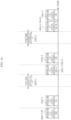
- FIG. 9 illustrates an example of a frame configuration when the horizontal axis indicates time.
- #1 symbol group 901-1 for stream 1 and #2 symbol group 902-1 for stream 2 are transmitted using the same frequency (the same frequency band)
- #2 symbol group 901-2 for stream 1 and #2 symbol group 902-2 for stream 2 are transmitted using the same frequency (the same frequency band)
- #3 symbol group 901-3 for stream 1 and #3 symbol group 902-3 for stream 2 are transmitted using the same frequency (the same frequency band).
- data symbol group A for stream 1 and “data symbol group A for stream 2” are generated from information, following the procedure in FIG. 8 .
- the symbol group, namely "data symbol group A-3 for stream 1" which includes the same symbols as symbols included in "data symbol group A for stream 1” are prepared.
- #1 symbol group 901-1 for stream 1 in FIG. 9 includes “data symbol group A-1 for stream 1"
- #2 symbol group 901-2 for stream 1 in FIG. 9 includes “data symbol group A-2 for stream 1”
- #3 symbol group 901-3 for stream 1 in FIG. 9 includes “data symbol group A-3 for stream 1”. Accordingly, #1 symbol group 901-1 for stream 1, #2 symbol group 901-2 for stream 1, and #3 symbol group 901-3 for stream 1 include the same data symbol group.
- the symbol group namely "data symbol group A-1 for stream 2" which includes the same symbols as symbols included in “data symbol group A for stream 2”
- the symbol group namely "data symbol group A-2 for stream 2” which includes the same symbols as symbols included in “data symbol group A for stream 2”
- the symbol group namely "data symbol group A-3 for stream 2" which includes the same symbols as symbols included in “data symbol group A for stream 2” are prepared.
- #1 symbol group 902-1 for stream 2 in FIG. 9 includes “data symbol group A-1 for stream 2
- #2 symbol group 902-2 for stream 2 in FIG. 9 includes “data symbol group A-2 for stream 2
- #3 symbol group 902-3 for stream 2 in FIG. 9 includes “data symbol group A-3 for stream 2”. Accordingly, #1 symbol group 902-1 for stream 2, #2 symbol group 902-2 for stream 2, and #3 symbol group 902-3 for stream 2 include the same data symbol group.
- 1001 denotes a control information symbol
- 1002 denotes a data symbol group for a stream.
- data symbol group 1002 for the stream includes symbols for transmitting "data symbol group A for stream 1" or "data symbol group A for stream 2" described with reference to FIG. 9 .
- a multi-carrier method such as the orthogonal frequency division multiplexing (OFDM) method may be used for the frame configuration in FIG. 10 , and symbols may be present in the direction of the frequency axis, in this case.
- the symbols may include a reference symbol for a receiving device to perform time synchronization and frequency synchronization, a reference symbol for a receiving device to detect a signal, and a reference symbol for a receiving device to perform channel estimation, for instance.
- the frame configuration is not limited to the configuration in FIG. 10 , and control information symbol 1001 and data symbol group 1002 for a stream may be arranged in any manner.
- the reference symbol may be referred to as a preamble and a pilot symbol.
- FIG. 11 illustrates an example of a configuration of symbols transmitted as a control information symbol in FIG. 10 , and the horizontal axis indicates time.
- a terminal receives "training symbol for a terminal to perform receiving directivity control" 1101 to determine a signal processing method for the directivity control for receiving, which is implemented by "signal processor 405" and/or “antennas 401-1 to 401-N” and/or “multipliers 603-1 to 603-L and processor 605".
- a terminal receives "symbol for notifying the number of transmission streams when multicasting is performed" 1102 so that the terminal is informed of the number of streams to be obtained.
- a terminal receives "symbol for notifying for which stream data symbols are" 1103 so that the terminal can be informed which stream has been successfully received among the streams which the base station is transmitting.
- the terminal since the terminal becomes aware that "the number of transmission streams is 2" and the obtained data symbols are "data symbols for stream 1", the terminal is aware that the terminal is to obtain "data symbols for stream 2". Thus, the terminal can start operation for searching for a symbol group for stream 2. For example, the terminal searches for one of transmission beams for transmitting #1 symbol group 902-1 for stream 2, #2 symbol group 902-2 for stream 2, and #3 symbol group 902-3 for stream 2 in FIG. 9 .
- the terminal obtains one of transmission beams for transmitting #1 symbol group 902-1 for stream 2, #2 symbol group 902-2 for stream 2, and #3 symbol group 902-3 for stream 2, to obtain data symbols for both streams 1 and 2.
- Configuring control information symbols in this manner yields an advantageous effect that a terminal can obtain data symbols precisely.
- the base station transmits data symbols using a plurality of transmission beams
- a terminal selectively receives a transmission beam with good quality among the plurality of transmission beams in multicast transmission and broadcast data transmission, and furthermore, transmission directivity control and receiving directivity control have been performed on modulated signals transmitted by the base station, thus achieving advantageous effects of increasing an area where high data receiving quality is achieved.
- a terminal performs receiving directivity control, yet advantageous effects can be obtained as mentioned above without the terminal performing receiving directivity control.
- the modulating method for "data symbol group for a stream" 1002 in FIG. 10 may be any modulating method, and a mapping method according to the modulating method for "data symbol group for a stream" 1002 may be changed for each symbol. Accordingly, a phase of a constellation may be changed for each symbol on an in-phase I-quadrature Q plane after mapping.
- FIG. 12 illustrates an example of a state of communication between a base station and terminals different from the example in FIG. 7 . Note that elements which operate in the same manner as those in FIG. 7 are assigned the same reference numerals in FIG. 12 .
- Base station 700 includes a plurality of antennas, and transmits a plurality of transmission signals through antenna 701 for transmission. At this time, base station 700 has a configuration as illustrated in, for example, FIG. 1 or 3 , and performs transmission beamforming (directivity control) by signal processor 102 (and/or weighting synthesizer 301) performing precoding (weighting synthesis).
- FIG. 12 illustrates transmission beam 1202-1 for transmitting "modulated signal 1", transmission beam 1202-2 for transmitting "modulated signal 1", and transmission beam 1202-3 for transmitting "modulated signal 1".
- FIG. 12 illustrates transmission beam 1203-1 for transmitting "modulated signal 2", transmission beam 1203-2 for transmitting "modulated signal 2", and transmission beam 1203-3 for transmitting "modulated signal 2".
- the present disclosure is not limited to such numbers, and the number of transmission beams for transmitting "modulated signal 1" may be at least 2 and the number of transmission beams for transmitting "modulated signal 2" may be at least 2.
- a detailed description of "modulated signal 1" and "modulated signal 2" will be given later.
- FIG. 12 includes terminals 704-1, 704-2, 704-3, 704-4, and 704-5, and the terminals have the same configuration as those in FIGS. 4 and 5 , for example.
- terminal 704-1 performs directivity control for receiving, via "signal processor 405" and/or “antennas 401-1 to 401-N” and/or “multipliers 603-1 to 603-L and processor 605", and forms receiving directivity 705-1 and receiving directivity 706-1.
- Receiving directivity 705-1 allows terminal 704-1 to receive and demodulate transmission beam 1202-1 for transmitting "modulated signal 1"
- receiving directivity 706-1 allows terminal 704-1 to receive and demodulate transmission beam 1203-1 for transmitting "modulated signal 2".
- terminal 704-2 performs directivity control for receiving, via "signal processor 405" and/or “antennas 401-1 to 401-N” and/or “multipliers 603-1 to 603-L and processor 605", and forms receiving directivity 705-2 and receiving directivity 706-2.
- Receiving directivity 705-2 allows terminal 704-2 to receive and demodulate transmission beam 1202-1 for transmitting "modulated signal 1”
- receiving directivity 706-2 allows terminal 704-2 to receive and demodulate transmission beam 1203-1 for transmitting "modulated signal 2".
- Terminal 704-3 performs directivity control for receiving, via "signal processor 405" and/or "antennas 401-1 to 401-N” and/or “multipliers 603-1 to 603-L and processor 605", and forms receiving directivity 705-3 and receiving directivity 706-3.
- Receiving directivity 705-3 allows terminal 704-3 to receive and demodulate transmission beam 1202-2 for transmitting "modulated signal 1"
- receiving directivity 706-3 allows terminal 704-3 to receive and demodulate transmission beam 1203-2 for transmitting "modulated signal 2”.
- Terminal 704-4 performs directivity control for receiving, via "signal processor 405" and/or “antennas 401-1 to 401-N” and/or “multipliers 603-1 to 603-L and processor 605", and forms receiving directivity 705-4 and receiving directivity 706-4.
- Receiving directivity 705-4 allows terminal 704-4 to receive and demodulate transmission beam 1202-3 for transmitting "modulated signal 1"
- receiving directivity 706-4 allows terminal 704-4 to receive and demodulate transmission beam 1203-2 for transmitting "modulated signal 2".
- Terminal 704-5 performs directivity control for receiving, via "signal processor 405" and/or "antennas 401-1 to 401-N” and/or “multipliers 603-1 to 603-L and processor 605", and forms receiving directivity 705-5 and receiving directivity 706-5.
- Receiving directivity 705-5 allows terminal 704-5 to receive and demodulate transmission beam 1202-3 for transmitting "modulated signal 1"
- receiving directivity 706-5 allows terminal 704-5 to receive and demodulate transmission beam 1203-3 for transmitting "modulated signal 2".
- a terminal selects, based on a spatial position, at least one transmission beam from among transmission beams 1202-1, 1202-2, and 1202-3 for transmitting "modulated signal 1", and can obtain "modulated signal 1" with high quality by directing a receiving directivity to the selected transmission beam(s). Further, the terminal selects, based on a spatial position, at least one transmission beam from among transmission beams 1203-1, 1203-2, and 1203-3 for transmitting "modulated signal 2", and can obtain "modulated signal 2" with high quality by directing a receiving directivity to the selected transmission beam(s).
- base station 700 transmits transmission beam 1202-1 for transmitting "modulated signal 1" and transmission beam 1203-1 for transmitting "modulated signal 2" using the same frequency (the same frequency band) at the same time. Then, base station 700 transmits transmission beam 1202-2 for transmitting "modulated signal 1” and transmission beam 1203-2 for transmitting "modulated signal 2" using the same frequency (the same frequency band) at the same time. Further, base station 700 transmits transmission beam 1202-3 for transmitting "modulated signal 1" and transmission beam 1203-3 for transmitting "modulated signal 2" using the same frequency (the same frequency band) at the same time.
- Transmission beams 1202-1, 1202-2, and 1202-3 for transmitting "modulated signal 1" may be beams having the same frequency (the same frequency band) or may be beams having different frequencies (different frequency bands).
- Transmission beams 1203-1, 1203-2, and 1203-3 for transmitting "modulated signal 2" may be beams having the same frequency (the same frequency band) or may be beams having different frequencies (different frequency bands).
- Setting unit 158 receives an input of setting signal 160.
- Setting signal 160 includes information with regard to "whether to perform transmission for multicasting or transmission for unicasting", and if the base station performs transmission as illustrated in FIG. 12 , information indicating "to perform transmission for multicasting" is input to setting unit 158 according to setting signal 160.
- Setting signal 160 includes information with regard to "the number of transmission modulated signals when multicasting is performed" and if the base station performs transmission as illustrated in FIG. 12 , information indicating that "the number of transmission modulated signals is 2" is input to setting unit 158 according to setting signal 160.
- Setting signal 160 may include information with regard to "how many transmission beams are to be used to transmit each modulated signal". If the base station performs transmission as illustrated in FIG. 12 , information indicating that "the number of transmission beams for transmitting modulated signal 1 is 3 and the number of transmission beams for transmitting modulated signal 2 is 3" is input to setting unit 158 according to setting signal 160.
- the base station in FIGS. 1 and 3 may transmit a control information symbol which includes, for instance, information with regard to "whether to perform transmission for multicasting or transmission for unicasting", information with regard to "the number of transmission modulated signals when multicasting is performed", information with regard to "how many transmission beams are to be used to transmit each modulated signal". Accordingly, a terminal can appropriately receive data. A configuration of a control information symbol will be later described in detail.
- FIG. 13 is a drawing for describing a relation between #i information 101-i in FIGS. 1 and 3 and "modulated signal 1" and “modulated signal 2" described with reference to FIG. 12 .
- #1 information 101-1 is subjected to error correction coding, for instance, and data obtained as a result of the error correction coding is obtained.
- the data obtained as a result of the error correction coding is named #1 transmission data.
- Data symbols are obtained by mapping #1 transmission data.
- the data symbols are separated into data symbols for stream 1 and data symbols for stream 2, so that data symbols (data symbol group) for stream 1 and data symbols (data symbol group) for stream 2 are obtained.
- a data symbol having symbol number i for stream 1 is s1(i) and a data symbol having symbol number i for stream 2 is s2(i).
- ⁇ (i) can be defined by a complex number (and thus may be a real number)
- ⁇ (i) can be defined by a complex number (and thus may be a real number)
- ⁇ (i) can be defined by a complex number (and thus may be a real number)
- ⁇ (i) can be defined by a complex number (and thus may be a real number)
- ⁇ (i) can be defined by a complex number (and thus may be a real number).
- ⁇ (i) may not be a function of symbol number i (may be a fixed value)
- ⁇ (i) may not be a function of symbol number i (may be a fixed value)
- ⁇ (i) may not be a function of symbol number i (may be a fixed value)
- ⁇ (i) may not be a function of symbol number i (may be a fixed value)
- ⁇ (i) may not be a function of symbol number i (may be a fixed value).
- a symbol group for modulated signal 1 which includes “signals in a data transmission area of modulated signal 1" which are constituted by data symbols is transmitted from the base station in FIG. 1 or 3 .
- a symbol group for modulated signal 2 which includes “signals in a data transmission area of modulated signal 2" which are constituted by data symbols is transmitted from the base station in FIG. 1 or 3 .
- signal processing such as phase modification and cyclic delay diversity (CDD) may be performed on “modulated signal 1" and "modulated signal 2". Note that the method for signal processing is not limited to those.
- FIG. 14 illustrates an example of a frame configuration when the horizontal axis indicates time.
- #1 symbol group (1401-1) for modulated signal 1 in FIG. 14 is a symbol group for transmission beam 1202-1 for transmitting data of modulated signal 1 in FIG. 12 .
- #2 symbol group (1401-2) for modulated signal 1 in FIG. 14 is a symbol group for transmission beam 1202-2 for transmitting data of modulated signal 1 in FIG. 12 .
- #3 symbol group (1401-3) for modulated signal 1 in FIG. 14 is a symbol group for transmission beam 1202-3 for transmitting data of modulated signal 1 in FIG. 12 .
- #1 symbol group (1402-1) for modulated signal 2 in FIG. 14 is a symbol group for transmission beam 1203-1 for transmitting data of modulated signal 2 in FIG. 12 .
- #2 symbol group (1402-2) for modulated signal 2 in FIG. 14 is a symbol group for transmission beam 1203-2 for transmitting data of modulated signal 2 in FIG. 12 .
- #3 symbol group (1402-3) for modulated signal 2 in FIG. 14 is a symbol group for transmission beam 1203-3 for transmitting data of modulated signal 2 in FIG. 12 .
- #1 symbol group (1401-1) for modulated signal 1, #2 symbol group (1401-2) for modulated signal 1, #3 symbol group (1401-3) for modulated signal 1, #1 symbol group (1402-1) for modulated signal 2, #2 symbol group (1402-2) for modulated signal 2, and #3 symbol group (1402-3) for modulated signal 2 are present in time interval 1, for example.
- #1 symbol group (1401-1) for modulated signal 1 and #1 symbol group (1402-1) for modulated signal 2 are transmitted using the same frequency (the same frequency band)
- #2 symbol group (1401-2) for modulated signal 1 and #2 symbol group (1402-2) for modulated signal 2 are transmitted using the same frequency (the same frequency band)
- #3 symbol group (1401-3) for modulated signal 1 and #3 symbol group (1402-3) for modulated signal 2 are transmitted using the same frequency (the same frequency band).
- signal Ain the data transmission area of modulated signal 1 and “signal A in the data transmission area of modulated signal 2" are generated from information in accordance with the procedure in FIG. 13 .
- #1 symbol group (1401-1) for modulated signal 1 in FIG. 14 includes “signal A-1 in the data transmission area of modulated signal 1”
- #2 symbol group (1401-2) for modulated signal 1 in FIG. 14 includes “signal A-2 in the data transmission area of modulated signal 1”
- #3 symbol group (1401-3) for modulated signal 1 in FIG. 14 includes “signal A-3 in the data transmission area of modulated signal 1”.
- #1 symbol group (1401-1) for modulated signal 1, #2 symbol group (1401-2) for modulated signal 1, and #3 symbol group (1401-3) for modulated signal 1 include equivalent signals.
- signal A-1 in the data transmission area of modulated signal 2 which is a signal constituted by a signal equivalent to a signal which constitutes "signal A in the data transmission area of modulated signal 2
- signal A-2 in the data transmission area of modulated signal 2 which is a signal constituted by a signal equivalent to a signal which constitutes "signal A in the data transmission area of modulated signal 2”
- signal A-3 in the data transmission area of modulated signal 2 which is a signal constituted by a signal equivalent to a signal which constitutes "signal A in the data transmission area of modulated signal 2” are prepared (thus, the signal which constitutes "signal A-1 in the data transmission area of modulated signal 2", the signal which constitutes "signal A-2 in the data transmission area of modulated signal 2”, and the signal which constitutes "signal A-3 in the data transmission area of modulated signal 2" are prepared (thus, the signal which constitutes "signal A-1 in the data transmission area of modulated signal 2", the signal which constitutes "signal A-2 in the data
- #1 symbol group (1402-1) for modulated signal 2 in FIG. 14 includes “signal A-1 in the data transmission area of modulated signal 2
- #2 symbol group (1402-2) for stream 2 in FIG. 14 includes “signal A-2 in the data transmission area of modulated signal 2
- #3 symbol group (1402-3) for modulated signal 2 in FIG. 14 includes “signal A-3 in the data transmission area of modulated signal 2”.
- #1 symbol group (1402-1) for modulated signal 2 #2 symbol group (1402-2) for modulated signal 2
- #3 symbol group (1402-3) for modulated signal 2 include equivalent signals.
- the horizontal axis indicates time
- 1501 indicates a control information symbol
- 1502 indicates a modulated signal transmission area for data transmission.
- modulated signal transmission area 1502 for data transmission includes symbols for transmitting "signal A in the data transmission area of modulated signal 1" or "signal A in the data transmission area of modulated signal 2" described with reference to FIG. 14 .
- a multi-carrier method such as an orthogonal frequency division multiplexing (OFDM) method may be used, and in this case, symbols may be present in the direction of the frequency axis.
- the symbols may each include a reference symbol for a receiving device to perform time synchronization and frequency synchronization, a reference symbol for a receiving device to detect a signal, and a reference symbol for a receiving device to perform channel estimation, for instance.
- the frame configuration is not limited to the configuration in FIG. 15 , and control information symbol 1501 and modulated signal transmission area 1502 for data transmission may be arranged in any manner.
- a reference symbol may also be called a preamble and a pilot symbol, for example.
- FIG. 16 illustrates an example of a configuration of symbols which are to be transmitted as a control information symbol in FIG. 15 , and the horizontal axis indicates time.
- 1601 denotes "a training symbol for a terminal to perform receiving directivity control”
- the terminal determines a signal processing method for the directivity control for receiving, which is performed by "signal processor 405" and/or “antennas 401-1 to 401-N” and/or “multipliers 603-1 to 603-L and processor 605", by receiving "training symbol for a terminal to perform receiving directivity control" 1601.
- 1602 denotes "a symbol for notifying the number of transmission modulated signals when multicasting is performed", and the terminal is informed of the number of modulated signals which are to be obtained, by receiving "symbol for notifying the number of transmission modulated signals when multicasting is performed" 1602.
- 1603 denotes "a symbol for notifying of which modulated signal a modulated signal transmission area for data transmission is", and the terminal can be informed of which modulated signal has been successfully received among modulated signals which the base station is transmitting, by receiving "symbol for notifying of which modulated signal a modulated signal transmission area for data transmission is" 1603.
- the base station is transmitting "modulated signal 1" and “modulated signal 2", and thus information indicated by “symbol for notifying the number of transmission modulated signals when multicasting is performed" 1602 is "2".
- #1 symbol group 1401-1 for modulated signal 1 in FIG. 14 is for transmitting a signal in the data transmission area of modulated signal 1, and thus information indicated by "symbol for notifying of which modulated signal a modulated signal transmission area for data transmission is" 1603 indicates "modulated signal 1".
- a terminal is assumed to receive #1 symbol group 1401-1 for modulated signal 1 in FIG. 14 .
- the terminal becomes aware that "the number of modulated signals is 2" is obtained from “symbol for notifying the number of transmission modulated signals when multicasting is performed" 1602, and that "modulated signal 1" from “symbol for notifying of which modulated signal a modulated signal transmission area for data transmission is” 1603.
- the terminal then becomes aware that "the number of present modulated signals is 2" and that the obtained modulated signal is "modulated signal 1", and thus the terminal is aware that "modulated signal 2" is to be obtained. Accordingly, the terminal can start operation of searching for "modulated signal 2".
- the terminal searches for one of transmission beams for any of "#1 symbol group 1402-1 for modulated signal 2", "#2 symbol group 1402-2 for modulated signal 2", "#3 symbol group 1402-3 for modulated signal 2" in FIG. 14 , for example.
- the terminal obtains both "modulated signal 1" and “modulated signal 2”, and can obtain data symbols for stream 1 and data symbols for stream 2 with high quality, by obtaining one transmission beam for "#1 symbol group 1402-1 for modulated signal 2", "#2 symbol group 1402-2 for modulated signal 2", and "#3 symbol group 1402-3 for modulated signal 2".
- Configuring a control information symbol in the above manner yields advantageous effects that the terminal can precisely obtain data symbols.
- the base station transmits data symbols using a plurality of transmission beams, and a terminal selectively receives a transmission beam with good quality among the plurality of transmission beams, thus achieving advantageous effects that a modulated signal which the base station has transmitted increases an area where high data receiving quality is achieved. This is because the base station performs transmission directivity control and receiving directivity control.
- a terminal performs receiving directivity control, yet advantageous effects can be obtained as mentioned above without the terminal performing receiving directivity control.
- each terminal obtains both a modulated signal of stream 1 and a modulated signal of stream 2 is described with reference to FIG. 7 , yet the present disclosure is not limited to such an embodiment.
- an embodiment in which a modulated signal desired to be obtained varies depending on a terminal may be achieved as in a case where there are a terminal which desires to obtain a modulated signal of stream 1, a terminal which desires to obtain a modulated signal of stream 2, and a terminal which desires to obtain both a modulated signal of stream 1 and a modulated signal of stream 2.
- Embodiment 1 has described a method in which a base station transmits data symbols using a plurality of transmission beams in multicast data transmission and broadcast data transmission.
- the present embodiment describes, as a variation of Embodiment 1, the case where a base station performs unicast data transmission as well as multicast data transmission and broadcast data transmission.
- FIG. 17 illustrates an example of a state of communication between the base station (or an access point, for instance) and terminals. Elements which operate in the same manner as those in FIG. 7 are assigned the same reference numerals, and a detailed description thereof is omitted.
- Base station 700 includes a plurality of antennas, and transmits a plurality of transmission signals through antenna 701 for transmission. At this time, base station 700 has a configuration as illustrated in, for example, FIG. 1 or 3 , and performs transmission beamforming (directivity control) by signal processor 102 (and/or weighting synthesizer 301) performing precoding (weighting synthesis).
- transmission beams 702-1, 702-2, 702-3, 703-1, 703-2, and 703-3 are as described with reference to FIG. 7 , and thus a description thereof is omitted.
- Terminals 704-1, 704-2, 704-3, 704-4, and 704-5, and receiving directivities 705-1, 705-2, 705-3, 705-4, 705-5, 706-1, 706-2, 706-3, 706-4, and 706-5 are as described with reference to FIG. 7 , and thus a description thereof is omitted.
- a distinguishing point is that the base station performs multicasting, as described with reference to FIG. 7 , and also base station 700 and a terminal (for example, 1702) perform unicast communication.
- base station 700 In addition to transmission beams for multicasting 702-1, 702-2, 702-3, 703-1, 703-2, and 703-3, in FIG. 17 , base station 700 generates transmission beam 1701 for unicasting, and transmits to terminal 1702 data therefor. Note that FIG. 17 illustrates an example in which base station 700 transmits one transmission beam 1701 to terminal 1702. Yet, the number of transmission beams is not limited to one, and base station 700 may transmit a plurality of transmission beams to terminal 1702 (may transmit a plurality of modulated signals).
- Terminal 1702 performs directivity control for receiving, via "signal processor 405" and/or “antennas 401-1 to 401-N” and/or “multipliers 603-1 to 603-L and signal processor 605", and forms receiving directivity 1703. This allows terminal 1702 to receive and demodulate transmission beam 1701.
- the base station performs precoding (weighting synthesis) using signal processor 102 (and/or weighting synthesizer 301) in the configuration as illustrated in FIG. 1 or 3 , for example.
- terminal 1702 transmits a modulated signal to base station 700
- terminal 1702 performs precoding (or weighting synthesis), and transmits transmission beam 1703.
- Base station 700 performs directivity control for receiving and forms receiving directivity 1701. Accordingly, base station 700 can receive and demodulate transmission beam 1703.
- base station 700 transmits transmission beam 702-1 for transmitting data of stream 1 and transmission beam 703-1 for transmitting data of stream 2, using the same frequency (the same frequency band) at the same time.
- Base station 700 transmits transmission beam 702-2 for transmitting data of stream 1 and transmission beam 703-2 for transmitting data of stream 2, using the same frequency (the same frequency band) at the same time.
- base station 700 transmits transmission beam 702-3 for transmitting data of stream 1 and transmission beam 703-3 for transmitting data of stream 2, using the same frequency (the same frequency band) at the same time.
- Transmission beams 702-1, 702-2, and 702-3 for transmitting data of stream 1 may be beams having the same frequency (the same frequency band), or may be beams having different frequencies (different frequency bands).
- Transmission beams 703-1, 703-2, and 703-3 for transmitting data of stream 2 may be beams having the same frequency (the same frequency band), or may be beams having different frequencies (different frequency bands).
- transmission beam 1701 for unicasting may be a beam having the same frequency (the same frequency band) as or a different frequency (a different frequency band) from those of transmission beams 702-1, 702-2, 702-3, 703-1, 703-2, and 703-3.
- Setting unit 158 receives an input of setting signal 160.
- Setting signal 160 includes information with regard to "whether to perform transmission for multicasting or transmission for unicasting", and if the base station performs transmission as illustrated in FIG. 17 , information indicating "to perform both transmission for multicasting and transmission for unicasting" is input to setting unit 158 according to setting signal 160.
- setting signal 160 includes information with regard to "the number of transmission streams when multicasting is performed" and if the base station performs transmission as illustrated in FIG. 17 , information indicating that "the number of transmission streams is 2" is input to setting unit 158 according to setting signal 160.
- Setting signal 160 may include information with regard to "how many transmission beams are to be used to transmit each stream". If the base station performs transmission as illustrated in FIG. 17 , information indicating that "the number of transmission beams for transmitting stream 1 is 3 and the number of transmission beams for transmitting stream 2 is 3" is input to setting unit 158 according to setting signal 160.
- the base station in FIGS. 1 and 3 may transmit a control information symbol which includes information with regard to "whether to perform transmission for multicasting or transmission for unicasting", information with regard to “the number of transmission streams when multicasting is performed”, information with regard to “how many transmission beams are to be used to transmit each stream", and others. Accordingly, a terminal can appropriately receive data.
- the base station may transmit, to a terminal with which the base station performs unicast communication, a control information symbol for training for the base station to perform directivity control, and a control information symbol for training for a terminal to perform directivity control.
- FIG. 18 illustrates an example of a state of communication between a base station (or an access point or the like) and terminals, and elements which operate in the same manner as those in FIGS. 7 and 12 are assigned the same reference numerals in FIG. 18 , and a detailed description thereof is omitted.
- Base station 700 includes a plurality of antennas, and transmits a plurality of transmission signals from antenna 701 for transmission. At this time, base station 700 has a configuration as illustrated in, for example, FIG. 1 or 3 , and performs transmission beamforming (directivity control) by signal processor 102 (and/or weighting synthesizer 301) performing precoding (weighting synthesis).
- a description of transmission beams 1202-1, 1202-2, 1202-3, 1203-1, 1203-2, and 1203-3 is as described with reference to FIG. 12 , and thus a description thereof is omitted.
- terminals 704-1, 704-2, 704-3, 704-4, and 704-5, and receiving directivities 705-1, 705-2, 705-3, 705-4, 705-5, 706-1, 706-2, 706-3, 706-4, and 706-5 is as given with reference to FIG. 12 , and thus a description thereof is omitted.
- a distinguishing point in FIG. 18 is that while the base station performs multicasting, as described with reference to FIG. 12 , base station 700 and a terminal (for example, 1702) perform unicast communication.
- base station 700 generates transmission beam 1701 for unicasting in addition to transmission beams 1202-1, 1202-2, 1202-3, 1203-1, 1203-2, and 1203-3 for multicasting, and transmits to terminal 1702 data therefor.
- FIG. 18 illustrates an example in which base station 700 transmits one transmission beam 1701 to terminal 1702, yet the number of transmission beams is not limited to one, and base station 700 may transmit a plurality of transmission beams to terminal 1702 (may transmit a plurality of modulated signals).
- Terminal 1702 performs directivity control for receiving, via "signal processor 405" and/or “antennas 401-1 to 401-N” and/or “multipliers 603-1 to 603-L and signal processor 605", and forms receiving directivity 1703. Accordingly, terminal 1702 can receive and demodulate transmission beam 1701.
- the base station performs precoding (weighting synthesis) in signal processor 102 (and/or, weighting synthesizer 301) in the configuration as illustrated in, for example, FIG. 1 or 3 .
- terminal 1702 transmits a modulated signal to base station 700
- terminal 1702 performs precoding (or weighting synthesis), and transmits transmission beam 1703
- base station 700 performs directivity control for receiving, and forms receiving directivity 1701. Accordingly, base station 700 can receive and demodulate transmission beam 1703.
- base station 700 transmits transmission beam 1202-1 for transmitting "modulated signal 1" and transmission beam 1203-1 for transmitting "modulated signal 2", using the same frequency (the same frequency band) at the same time. Then, base station 700 transmits transmission beam 1202-2 for transmitting "modulated signal 1” and transmission beam 1203-2 for transmitting "modulated signal 2", using the same frequency (the same frequency band) at the same time. Further, base station 700 transmits transmission beam 1202-3 for transmitting "modulated signal 1" and transmission beam 1203-3 for transmitting "modulated signal 2", using the same frequency (the same frequency band) at the same time.
- Transmission beams 1202-1, 1202-2, and 1202-3 for transmitting "modulated signal 1" may be beams having the same frequency (the same frequency band) or may be beams having different frequencies (different frequency bands).
- Transmission beams 1203-1, 1203-2, and 1203-3 for transmitting "modulated signal 2" may be beams having the same frequency (the same frequency band) or may be beams having different frequencies (different frequency bands).
- Transmission beam 1701 for unicasting may be a beam having the same frequency (the same frequency band) as or a different frequency (different frequency band) from those of transmission beams 1202-1, 1202-2, 1202-3, 1203-1, 1203-2, and 1203-3.
- Setting unit 158 receives an input of setting signal 160.
- Setting signal 160 includes information with regard to "whether to perform transmission for multicasting or transmission for unicasting", and if the base station performs transmission as illustrated in FIG. 18 , information indicating "to perform both transmission for multicasting and transmission for unicasting" is input to setting unit 158 according to setting signal 160.
- Setting signal 160 also includes information with regard to "the number of transmission streams when multicasting is performed" and if the base station performs transmission as illustrated in FIG. 18 , information indicating that "the number of transmission streams is 2" is input to setting unit 158 according to setting signal 160.
- Setting signal 160 may include information with regard to "how many transmission beams are to be used to transmit each stream". If the base station performs transmission as illustrated in FIG. 18 , information indicating that "the number of transmission beams for transmitting stream 1 is 3 and the number of transmission beams for transmitting stream 2 is 3" is input to setting unit 158 according to setting signal 160.
- the base station in FIGS. 1 and 3 may transmit a control information symbol which includes information with regard to "whether to perform transmission for multicasting or transmission for unicasting", information with regard to “the number of transmission streams when multicasting is performed”, and information with regard to "how many transmission beams are to be used to transmit each stream", for instance. Accordingly, a terminal can appropriately receive data.
- the base station may transmit, to a terminal with which the base station performs unicast communication, a control information symbol for training for the base station to perform directivity control, and a control information symbol for training for a terminal to perform directivity control.
- Embodiment 1 The following describes the case where the base station transmits a plurality of data by multicasting, as a variation of Embodiment 1.
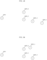
- FIG. 19 illustrates an example of a state of communication between the base station (or an access point, for instance) and terminals, and elements which operate in the same manner as those in FIG. 7 are assigned the same reference numerals in FIG. 19 , so that a detailed description thereof is omitted.
- Base station 700 includes a plurality of antennas, and transmits a plurality of transmission signals through antenna 701 for transmission. At this time, base station 700 has a configuration as illustrated in, for example, FIG. 1 or 3 , and performs transmission beamforming (directivity control) by signal processor 102 (and/or weighting synthesizer 301) performing precoding (weighting synthesis).
- a description of transmission beams 702-1, 702-2, 702-3, 703-1, 703-2, and 703-3 is as given with reference to FIG. 7 , and thus a description thereof is omitted.
- terminals 704-1, 704-2, 704-3, 704-4, and 704-5 and receiving directivities 705-1, 705-2, 705-3, 705-4, 705-5, 706-1, 706-2, 706-3, 706-4, and 706-5 is as described with reference to FIG. 7 , and thus a description thereof is omitted.
- Base station 700 transmits transmission beams 1901-1, 1901-2, 1902-1, and 1902-2, in addition to transmission beams 702-1, 702-2, 702-3, 703-1, 703-2, and 703-3.
- Transmission beam 1901-1 is a transmission beam for transmitting data of stream 3.
- Transmission beam 1901-2 is also a transmission beam for transmitting data of stream 3.
- Transmission beam 1902-1 is a transmission beam for transmitting data of stream 4.
- Transmission beam 1902-2 is also a transmission beam for transmitting data of stream 4.
- Reference numerals 704-1, 704-2, 704-3, 704-4, 704-5, 1903-1, 1903-2, and 1903-3 denote terminals, and each have a configuration as illustrated in FIGS. 4 and 5 , for example. Note that operation of terminals 704-1, 704-2, 704-3, 704-4, and 704-5 is as described with reference to FIG. 7 .
- Terminal 1903-1 performs directivity control for receiving, via "signal processor 405" and/or “antennas 401-1 to 401-N” and/or “multipliers 603-1 to 603-L and processor 605", and forms receiving directivity 1904-1 and receiving directivity 1905-1.
- Receiving directivity 1904-1 allows terminal 1903-1 to receive and demodulate transmission beam 1901-2 for transmitting data of stream 3
- receiving directivity 1905-1 allows terminal 1903-1 to receive and demodulate transmission beam 1902-2 for transmitting data of stream 4.
- Terminal 1903-2 performs directivity control for receiving, via "signal processor 405" and/or "antennas 401-1 to 401-N” and/or “multipliers 603-1 to 603-L and processor 605", and forms receiving directivity 1904-2 and receiving directivity 1905-2.
- Receiving directivity 1904-2 allows terminal 1903-2 to receive and demodulate transmission beam 1902-1 for transmitting data of stream 4, and receiving directivity 1905-2 allows terminal 1903-2 to receive and demodulate transmission beam 1901-2 for transmitting data of stream 3.
- Terminal 1903-3 performs directivity control for receiving, via "signal processor 405" and/or "antennas 401-1 to 401-N” and/or “multipliers 603-1 to 603-L and processor 605", and forms receiving directivity 1904-3 and receiving directivity 1905-3.
- Receiving directivity 1904-3 allows terminal 1903-3 to receive and demodulate transmission beam 1901-1 for transmitting data of stream 3
- receiving directivity 1905-3 allows terminal 1903-3 to receive and demodulate transmission beam 1902-1 for transmitting data of stream 4.
- Terminal 1903-4 performs directivity control for receiving, via "signal processor 405" and/or “antennas 401-1 to 401-N” and/or “multipliers 603-1 to 603-L and processor 605", and forms receiving directivity 1904-4 and receiving directivity 1905-4.
- Receiving directivity 1904-4 allows terminal 1903-4 to receive and demodulate transmission beam 703-1 for transmitting data of stream 2
- receiving directivity 1905-4 allows terminal 1903-4 to receive and demodulate transmission beam 1901-1 for transmitting data of stream 3.
- a distinguishing point is that the base station transmits a plurality of streams each including data for multicasting, and also transmits each stream using a plurality of transmission beams, and each terminal selectively receives one or more transmission beams for one more streams among a plurality of streams.
- base station 700 transmits transmission beam 702-1 for transmitting data of stream 1 and transmission beam 703-1 for transmitting data of stream 2, using the same frequency (the same frequency band) at the same time.
- Base station 700 transmits transmission beam 702-2 for transmitting data of stream 1 and transmission beam 703-2 for transmitting data of stream 2, using the same frequency (the same frequency band) at the same time.
- base station 700 transmits transmission beam 702-3 for transmitting data of stream 1 and transmission beam 703-3 for transmitting data of stream 2, using the same frequency (the same frequency band) at the same time.
- Base station 700 transmits transmission beam 1901-1 for transmitting data of stream 3 and transmission beam 1902-1 for transmitting data of stream 4, using the same frequency (the same frequency band) at the same time.
- Base station 700 transmits transmission beam 1901-2 for transmitting data of stream 3 and transmission beam 1902-2 for transmitting data of stream 4, using the same frequency (the same frequency band) at the same time.
- Transmission beams 702-1, 702-2, and 702-3 for transmitting data of stream 1 may be beams having the same frequency (the same frequency band), or may be beams having different frequencies (different frequency bands).
- Transmission beams 703-1, 703-2, and 703-3 for transmitting data of stream 2 may be beams having the same frequency (the same frequency band), or may be beams having different frequencies (different frequency bands).
- Transmission beams 1901-1 and 1901-2 for transmitting data of stream 3 may be beams having the same frequency (the same frequency band), or may be beams having different frequencies (different frequency bands).
- Transmission beams 1902-1 and 1902-2 for transmitting data of stream 4 may be beams having the same frequency (the same frequency band), or may be beams having different frequencies (different frequency bands).
- data symbols for stream 1 and data symbols for stream 2 may be generated from #1 information 101-1 in FIG. 1
- data symbols for stream 3 and data symbols for stream 4 may be generated from #2 information 101-2.
- error correction coding may be performed on each of #1 information 101-1 and #2 information 101-2, and thereafter data symbols may be generated therefrom.
- Data symbols for stream 1 may be generated from #1 information 101-1 in FIG. 1
- data symbols for stream 2 may be generated from #2 information 101-2 in FIG. 1
- data symbols for stream 3 may be generated from #3 information 101-3 in FIG. 1
- data symbols for stream 4 may be generated from #4 information 101-4 in FIG. 1 .
- error correction coding may be performed on each of#1 information 101-1, #2 information 101-2, #3 information 101-3, and #4 information 101-4, and thereafter data symbols may be generated therefrom.
- data symbols for streams may be generated from any of the information in FIG. 1 . This yields advantageous effect that a terminal can selectively obtain a stream for multicasting.
- Setting unit 158 receives an input of setting signal 160.
- Setting signal 160 includes information with regard to "whether to perform transmission for multicasting or transmission for unicasting", and if the base station performs transmission as illustrated in FIG. 19 , information indicating "to perform transmission for multicasting" is input to setting unit 158 according to setting signal 160.
- Setting signal 160 includes information with regard to "the number of transmission streams when multicasting is performed" and if the base station performs transmission as illustrated in FIG. 19 , information indicating that "the number of transmission streams is 4" is input to setting unit 158 according to setting signal 160.
- Setting signal 160 may include information with regard to "how many transmission beams are to be used to transmit each stream". If the base station performs transmission as illustrated in FIG. 19 , information indicating that "the number of transmission beams for transmitting stream 1 is 3, the number of transmission beams for transmitting stream 2 is 3, the number of transmission beams for transmitting stream 3 is 2, and the number of transmission beams for transmitting stream 4 is 2" is input to setting unit 158 according to setting signal 160.
- the base station in FIGS. 1 and 3 may transmit a control information symbol which includes, for instance, information with regard to "whether to perform transmission for multicasting or transmission for unicasting", information with regard to “the number of transmission streams when multicasting is performed", and information with regard to "how many transmission beams are to be used to transmit each stream". Accordingly, a terminal can appropriately receive data.
- Embodiment 1 The following describes the case where the base station transmits a plurality of data by multicasting, as a variation of Embodiment 1.
- FIG. 20 illustrates an example of a state of communication between the base station (or an access point, for instance) and terminals, and elements which operate in the same manner as those in FIGS. 7 , 12 , and 19 are assigned the same reference numerals in FIG. 20 , so that a detailed description thereof is omitted.
- Base station 700 includes a plurality of antennas, and transmits a plurality of transmission signals from antenna 701 for transmission. At this time, base station 700 has a configuration as illustrated in, for example, FIG. 1 or 3 , and performs transmission beamforming (directivity control) by signal processor 102 (and/or weighting synthesizer 301) performing precoding (weighting synthesis).
- a description of transmission beams 1202-1, 1202-2, 1202-3, 1203-1, 1203-2, and 1203-3 overlaps a description given with reference to FIG. 12 , and thus a description thereof is omitted.
- terminals 704-1, 704-2, 704-3, 704-4, and 704-5, and receiving directivity 705-1, 705-2, 705-3, 705-4, 705-5, 706-1, 706-2, 706-3, 706-4, and 706-5 overlaps a description given with reference to FIG. 12 , and thus a description thereof is omitted.
- Base station 700 transmits transmission beams 2001-1, 2001-2, 2002-1, and 2002-2, in addition to transmission beams 1202-1, 1202-2, 1202-3, 1203-1, 1203-2, and 1203-3.
- Transmission beam 2001-1 is a transmission beam for transmitting "modulated signal 3".
- Transmission beam 2001-2 is also a transmission beam for transmitting "modulated signal 3".
- Transmission beam 2002-1 is a transmission beam for transmitting "modulated signal 4".
- Transmission beam 2002-2 is also a transmission beam for transmitting "modulated signal 4".
- Terminals 704-1, 704-2, 704-3, 704-4, 704-5, 1903-1, 1903-2, and 1903-3 have the same configuration as those illustrated in FIGS. 4 and 5 , for example. Note that operation of terminals 704-1, 704-2, 704-3, 704-4, and 704-5 is the same as a description given with reference to FIG. 7 .
- Terminal 1903-1 performs directivity control for receiving, via "signal processor 405" and/or “antennas 401-1 to 401-N” and/or “multipliers 603-1 to 603-L and processor 605", and forms receiving directivity 1904-1 and receiving directivity 1905-1.
- Receiving directivity 1904-1 allows terminal 1903-1 to receive and demodulate transmission beam 2001-2 for transmitting "modulated signal 3"
- receiving directivity 1905-1 allows terminal 1903-1 to receive and demodulate transmission beam 2002-2 for transmitting "modulated signal 4".
- Terminal 1903-2 performs directivity control for receiving, via "signal processor 405" and/or “antennas 401-1 to 401-N” and/or “multipliers 603-1 to 603-L and processor 605", and forms receiving directivity 1904-2 and receiving directivity 1905-2.
- Receiving directivity 1904-2 allows terminal 1903-2 to receive and demodulate transmission beam 2002-1 for transmitting "modulated signal 4"
- receiving directivity 1905-2 allows terminal 1903-2 to receive and demodulate transmission beam 2001-2 for transmitting "modulated signal 3".
- Terminal 1903-3 performs directivity control for receiving, via "signal processor 405" and/or "antennas 401-1 to 401-N” and/or “multipliers 603-1 to 603-L and processor 605", and forms receiving directivity 1904-3 and receiving directivity 1905-3.
- Receiving directivity 1904-3 allows terminal 1903-3 to receive and demodulate transmission beam 2001-1 for transmitting "modulated signal 3"
- receiving directivity 1905-3 allows terminal 1903-3 to receive and demodulate transmission beam 2002-1 for transmitting "modulated signal 4".
- Terminal 1903-4 performs directivity control for receiving, via "signal processor 405" and/or “antennas 401-1 to 401-N” and/or “multipliers 603-1 to 603-L and processor 605", and forms receiving directivity 1904-4 and receiving directivity 1905-4.
- Receiving directivity 1904-4 allows terminal 1903-4 to receive and demodulate transmission beam 2001-1 for transmitting "modulated signal 3"
- receiving directivity 1905-4 allows terminal 1903-4 to receive and demodulate transmission beam 2002-1 for transmitting "modulated signal 4".
- the base station transmits a plurality of modulated signals each including data for multicasting, and transmits each modulated signal using a plurality of transmission beams.
- Each terminal selectively receives one or more transmission beams used to transmit one or more streams among the plurality of modulated signals.
- base station 700 transmits transmission beam 1202-1 for transmitting "modulated signal 1" and transmission beam 1203-1 for transmitting "modulated signal 2", using the same frequency (the same frequency band) at the same time. Then, base station 700 transmits transmission beam 1202-2 for transmitting "modulated signal 1” and transmission beam 1203-2 for transmitting "modulated signal 2", using the same frequency (the same frequency band) at the same time. Further, base station 700 transmits transmission beam 1202-3 for transmitting "modulated signal 1" and transmission beam 1203-3 for transmitting "modulated signal 2", using the same frequency (the same frequency band) at the same time.
- Base station 700 transmits transmission beam 2001-1 for transmitting "modulated signal 3" and transmission beam 2002-1 for transmitting "modulated signal 4", using the same frequency (the same frequency band) at the same time. Then, base station 700 transmits transmission beam 2001-2 for transmitting "modulated signal 3" and transmission beam 2002-2 for transmitting "modulated signal 4", using the same frequency (the same frequency band) at the same time.
- Transmission beams 702-1, 702-2, and 702-3 for transmitting data of stream 1 may be beams having the same frequency (the same frequency band), or may be beams having different frequencies (different frequency bands).
- Transmission beams 703-1, 703-2, and 703-3 for transmitting data of stream 2 may be beams having the same frequency (the same frequency band), or may be beams having different frequencies (different frequency bands).
- Transmission beams 2001-1 and 2001-2 for transmitting "modulated signal 3" may be beams having the same frequency (the same frequency band) or may be beams having different frequencies (different frequency bands).
- Transmission beams 2002-1 and 2002-2 for transmitting "modulated signal 4" may be beams having the same frequency (the same frequency band) or may be beams having different frequencies (different frequency bands).
- Setting unit 158 receives an input of setting signal 160.
- Setting signal 160 includes information with regard to "whether to perform transmission for multicasting or transmission for unicasting", and if the base station performs transmission illustrated in FIG. 19 , information indicating "to perform transmission for multicasting" is input to setting unit 158 according to setting signal 160.
- Setting signal 160 includes information with regard to "the number of transmission modulated signals when multicasting is performed", and if the base station performs transmission illustrated in FIG. 20 , information indicating "the number of transmission modulated signals is 4" is input to setting unit 158 according to setting signal 160.
- Setting signal 160 may include information with regard to "how many transmission beams are to be used to transmit each modulated signal".
- information indicating that "the number of transmission beams for transmitting modulated signal 1 is 3, the number of transmission beams for transmitting modulated signal 2 is 3, the number of transmission beams for transmitting modulated signal 3 is 2, and the number of transmission beams for transmitting modulated signal 4 is 2" is input to setting unit 158 according to setting signal 160.
- the base station in FIGS. 1 and 3 may transmit a control information symbol which includes, for instance, information with regard to "whether to perform transmission for multicasting or transmission for unicasting", information with regard to “the number of transmission streams when multicasting is performed”, information with regard to "how many transmission beams are to be used to transmit each stream". Accordingly, a terminal can appropriately receive data.
- a terminal receives both a transmission beam for "modulated signal 1", and a transmission beam for "modulated signal 2", the terminal can obtain data of stream 1 and data of stream 2 with high receiving quality.
- a terminal receives both a transmission beam for "modulated signal 3", and a transmission beam for "modulated signal 4", the terminal can obtain data of stream 3 and data of stream 4 with high receiving quality.
- FIG. 20 illustrates an example in which the base station transmits "modulated signal 1", “modulated signal 2", “modulated signal 3", and “modulated signal 4", yet the base station may transmit "modulated signal 5" and “modulated signal 6" for transmitting data of stream 5 and data of stream 6, respectively, and may transmit more modulated signals in order to transmit more streams. Note that the base station transmits each of the modulated signals using one or more transmission beams.
- one or more transmission beams for unicasting may be present.
- #2 information 101-2 is subjected to processing such as error correction coding, and data obtained as a result of the error correction coding is obtained.
- the data obtained as a result of the error correction coding is named #2 transmission data.
- Data symbols are obtained by mapping #2 transmission data.
- the data symbols are separated into data symbols for stream 3 and data symbols for stream 4, so that data symbols (data symbol group) for stream 3 and data symbols (data symbol group) for stream 4 are obtained.
- a data symbol having symbol number i for stream 3 is s3(i)
- a data symbol having symbol number i for stream 4 is s4(i).
- e(i), f(i), g(i), and h(i) are indicated, e(i), f(i), g(i), and h(i) may not be functions of symbol number i and may be fixed values.
- the base station in FIG. 1 or 3 transmits "a symbol group for modulated signal 3" which includes “signals in a data transmission area of modulated signal 3" which are constituted by data symbols. Then, the base station in FIG. 1 or 3 transmits "a symbol group for modulated signal 4" which includes "signals in a data transmission area of modulated signal 4" which are constituted by data symbols.
- each exemplary embodiment and the other contents are only examples.
- a “modulating method, an error correction coding method (an error correction code, a code length, a coding rate and the like to be used), control information and the like” are exemplified, it is possible to carry out the present disclosure with the same configuration even when other types of a “modulating method, an error correction coding method (an error correction code, a code length, a coding rate and the like to be used), control information and the like" are applied.
- amplitude phase shift keying (APSK), pulse amplitude modulation (PAM), phase shift keying (PSK), and quadrature amplitude modulation (QAM) may be applied, or in each modulating method, uniform mapping or non-uniform mapping may be performed.
- APSK includes 16APSK, 64APSK, 128APSK, 256APSK, 1024APSK, and 4096APSK, for example.
- PAM includes 4PAM, 8PAM, 16PAM, 64PAM, 128PAM, 256PAM, 1024PAM, and 4096PAM, for example.
- PSK includes BPSK, QPSK, 8PSK, 16PSK, 64PSK, 128PSK, 256PSK, 1024PSK, and 4096PSK, for example.
- QAM includes 4QAM, 8QAM, 16QAM, 64QAM, 128QAM, 256QAM, 1024QAM, and 4096QAM, for example.
- a method for arranging signal points, such as 2 signal points, 4 signal points, 8 signal points, 16 signal points, 64 signal points, 128 signal points, 256 signal points, and 1024 signal points on an I-Q plane (a modulating method having 2 signal points, 4 signal points, 8 signal points, 16 signal points, 64 signal points, 128 signal points, 256 signal points, and 1024 signal points, for instance) is not limited to a signal point arranging method according to the modulating methods described herein.
- the "base station” described herein may be a broadcast station, a base station, an access point, a terminal, or a mobile phone, for example.
- the "terminal” described herein may be a television, a radio, a terminal, a personal computer, a mobile phone, an access point, or a base station, for instance.
- the "base station” and the “terminal” in the present disclosure may be devices having a communication function, and such devices may be configured to be connected with devices for running applications such as a television, a radio, a personal computer, and a mobile phone, via a certain interface.
- symbols other than data symbols such as, for example, a pilot symbol and a symbol for control information may be arranged in any manner in frames.
- any names may be given to a pilot symbol and a symbol for control information, and such symbols may be, for example, known symbols modulated using PSK modulation in a transmitting device or a receiving device.
- the receiving device may be able to learn a symbol transmitted by the transmitting device by establishing synchronization.
- the receiving device performs, using the symbol, frequency synchronization, time synchronization, channel estimation of each modulated signal (estimation of channel state information (CSI)), and signal detection, for instance.
- CSI channel state information
- a pilot symbol may be referred to as a preamble, a unique word, a postamble, or a reference symbol, for instance.
- control information symbol is a symbol for transmitting information that is used for realizing communication other than communication for data (data of an application, for instance) and that is to be transmitted to a communicating party (for example, a modulating method used for communication, an error correction coding method, a coding rate of the error correction coding method, setting information in an upper layer, and the like).
- a communicating party for example, a modulating method used for communication, an error correction coding method, a coding rate of the error correction coding method, setting information in an upper layer, and the like.
- the present disclosure is not limited to each exemplary embodiment, and can be carried out with various modifications.
- the case where the present disclosure is performed as a communication device is described in each exemplary embodiment.
- the present disclosure is not limited to this case, and this communication method can also be used as software.
- a program for executing the above-described communication method may be stored in a ROM (Read Only Memory) in advance, and a CPU (Central Processing Unit) may be caused to operate this program.
- ROM Read Only Memory
- CPU Central Processing Unit
- the program for executing the above-described communication method may be stored in a computer-readable storage medium, the program stored in the recording medium may be recorded in a RAM (Random Access Memory) of a computer, and the computer may be caused to operate according to this program.
- a RAM Random Access Memory
- the configurations of the above-described exemplary embodiments may be each realized as an LSI (Large Scale Integration) which is typically an integrated circuit having an input terminal and an output terminal.
- the configurations may be separately formed as one chip, or all or at least one of the configurations of the exemplary embodiments may be formed as one chip.
- the LSI is described here, but the integrated circuit may also be referred to as an IC (Integrated Circuit), a system LSI, a super LSI, or an ultra LSI, depending on a degree of integration.
- a circuit integration technique is not limited to the LSI, and may be realized by a dedicated circuit or a general purpose processor.
- a programmable FPGA Field Programmable Gate Array
- a reconfigurable processor which is reconfigurable in connection or settings of circuit cells inside the LSI may be used.
- the present embodiment describes a multicast communication method when beamforming different from the beamforming in Embodiments 1 and 2 is applied.
- the configuration of the base station is as described with reference to FIGS. 1 to 3 in Embodiment 1, and thus a description of portions which operate in the same manner as those in Embodiment 1 is omitted. Also, the configuration of a terminal which communicates with a base station is as described with reference to FIGS. 4 to 6 in Embodiment 1, and thus a description of portions which operate in the same manner as those in Embodiment 1 is omitted.
- the following describes an example of operation of a base station and a terminal in the present embodiment.
- FIG. 22 illustrates the case where the base station transmits a transmission stream for multicasting to one terminal.
- base station 700 transmits transmission beam 2201-1 for "stream 1-1 (a first beam for stream 1) (for multicasting)" from an antenna for transmission to terminal 2202-1, and terminal 2202-1 performs directivity control to generate receiving directivity 2203-1, and receives transmission beam 2201-1 for "stream 1-1".
- stream 1-1 a first beam for stream 1 (for multicasting)
- FIG. 23 is for describing a "procedure for performing communication between a base station and a terminal" to achieve the state of communication between the base station and the terminal as illustrated in FIG. 22 .
- the terminal transmits a "request to transmit stream 1 by multicasting" to a base station.
- the base station Upon receiving [23-1], the base station becomes aware that the base station "is not transmitting stream 1 by multicasting". Then, the base station transmits, to the terminal, a training symbol for transmission directivity control, and a training symbol for receiving directivity control, in order to transmit stream 1 by multicasting.
- the terminal receives the training symbol for transmission directivity control and the training symbol for receiving directivity control transmitted by the base station, and transmits feedback information to the base station in order that the base station performs transmission directivity control and the terminal performs receiving directivity control.
- the base station determines a method for transmission directivity control (determines, for instance, a weighting factor to be used for directivity control), based on the feedback information transmitted by the terminal, performs transmission directivity control, and transmits data symbols for stream 1.
- the terminal determines a receiving directivity control method (determines, for instance, a weighting factor to be used for directivity control), and starts receiving the data symbols for stream 1 transmitted by the base station.
- FIG. 23 illustrates, as an example, the case in which the terminal performs receiving directivity control, yet the terminal may not perform receiving directivity control. In such a case, the base station may not transmit a training symbol for receiving directivity control and the terminal does not determine a receiving directivity control method, in FIG. 23 .
- the base station When the base station performs transmission directivity control, if the base station has a configuration in FIG. 1 , for example, multiplication coefficients for multipliers 204-1, 204-2, 204-3, and 204-4 in FIG. 2 are determined, whereas if the base station has a configuration in FIG. 3 , weighting factors for weighting synthesizer 301 are determined, for example. Note that the number of streams to be transmitted is "1" in FIG. 22 , yet the present disclosure is not limited to this.
- multiplication coefficients for multipliers 503-1, 503-2, 503-3, and 503-4 in FIG. 5 are determined, whereas when the terminal has the configuration in FIG. 6 , multiplication coefficients for multipliers 603-1, 603-2, ..., and 603-L, for example, are determined.
- FIG. 24 is a diagram illustrating examples of symbols which the base station transmits and symbols which a terminal transmits along a time-axis, when the base station in FIG. 23 transmits a symbol for transmission directivity control, a symbol for receiving directivity control, and data symbols.
- (a) is a diagram illustrating examples of symbols which the base station transmits, along the time-axis
- (b) is a diagram illustrating examples of symbols which the terminal transmits along the time-axis, while the horizontal axis indicates time in both of (a) and (b).
- base station transmission directivity control training symbol 2401 as illustrated in FIG. 24 .
- base station transmission directivity control training symbol 2401 includes a control information symbol and a known PSK symbol.
- the terminal receives "base station transmission directivity control training symbol" 2401 transmitted by the base station, and transmits, as feedback information symbol 2402, information on an antenna to be used by the base station for transmission and information on multiplication coefficients (or weighting factors) to be used for directivity control, for example.
- the base station receives "feedback information symbol” 2402 transmitted by the terminal, determines an antenna to be used for transmission from feedback information symbol 2402, and determines a coefficient to be used for transmission directivity control from feedback information symbol 2402. After that, the base station transmits "terminal receiving directivity control training symbol" 2403.
- "terminal receiving directivity control training symbol” 2403 includes a control information symbol and a known PSK symbol.
- the terminal receives "terminal receiving directivity control training symbol" 2403 transmitted by the base station, and determines an antenna which the terminal is to use for receiving and a multiplication coefficient which the terminal is to use for receiving directivity control, for example. Then, the terminal transmits feedback information symbol 2404, notifying that preparation for receiving data symbols is completed.
- the base station receives "feedback information symbol" 2404 transmitted by the terminal, and outputs data symbols 2405 based on feedback information symbol 2404.
- Base station transmission directivity control training symbol 2401
- feedback information symbol 2402
- terminal receiving directivity control training symbol 2403
- feedback information symbol 2404
- data symbols 2405 may each include: a preamble for signal detection, time synchronization, frequency synchronization, frequency offset estimation, and channel estimation, a reference symbol, a pilot symbol, and a symbol for transmitting control information, for instance.
- FIG. 25 illustrates examples of symbols which the base station transmits when the base station transmits data symbols for stream 1 after communication between the base station and the terminal in FIG. 23 is completed, while the horizontal axis indicates time.
- the base station transmits a first data symbol for transmission beam 1 for stream 1 as "stream 1-1 data symbol (1) (for multicasting)" 2501-1-1. After that, interval 2502-1 in which data symbols can be transmitted is arranged.
- the base station transmits a second data symbol for transmission beam 1 for stream 1 (for multicasting) as "stream 1-1 data symbol (2) (for multicasting)" 2501-1-2. After that, interval 2502-2 in which data symbols can be transmitted is arranged.
- the base station transmits a third data symbol for transmission beam 1 for stream 1 (for multicasting) as "stream 1-1 data symbol (3) (for multicasting)" 2501-1-3.
- the base station transmits data symbols for "stream (for multicasting) 1-1" 2201-1 illustrated in FIG. 22 .
- "stream 1-1 data symbol (1) (for multicasting)" 2501-1-1, "stream 1-1 data symbol (2) (for multicasting)" 2501-1-2, "data symbol 1-1 data symbol (3) (for multicasting)" 2501-1-3, and so on may each include, other than a data symbol, a preamble for signal detection, time synchronization, frequency synchronization, frequency offset estimation, and channel estimation, a reference symbol, a pilot symbol, and a symbol for transmitting control information, for instance.
- interval 2502-1 in which data symbols can be transmitted includes unicast transmitting interval 2503-1
- interval 2502-2 in which data symbols can be transmitted includes unicast transmitting interval 2503-2.
- a frame includes unicast transmitting intervals 2503-1 and 2503-2.
- the base station may transmit symbols for multicasting in an interval within interval 2502-1 in which data symbols can be transmitted and other than unicast transmitting interval 2503-1, and an interval within interval 2502-2 in which data symbols can be transmitted and other than unicast transmitting interval 2503-2. This point will be described later using an example.
- the unicast transmitting intervals may not be in the temporal positions as illustrated in FIG. 25 , and may be arranged in any temporal positions. Note that in the unicast transmitting intervals, the base station may transmit symbols or the terminal may transmit symbols.
- the base station can directly set a unicast transmitting interval, or as another method, the base station may set the maximum transmission-data transmission speed for transmitting symbols for multicasting.
- a unicast transmitting interval corresponding to 500 Mbps can be set.
- the base station can indirectly set a unicast transmitting interval. Note that another specific example will be described later.
- FIG. 25 illustrates a frame configuration in which "stream 1-1 data symbol (1) (for multicasting)" 2501-1-1, "stream 1-1 data symbol (2) (for multicasting)" 2501-1-2, and “stream 1-1 data symbol (3) (for multicasting)" 2501-1-3 are present, yet the present disclosure is not limited to such a frame configuration.
- a data symbol for a stream for multicasting other than stream 1 (stream 1-1) may be present, a data symbol for stream 1-2 which is a second transmission beam for stream 1, and a data symbol for stream 1-3 which is a third transmission beam for stream 1 may be present. This point will be described later.
- FIG. 26 illustrates a state when a terminal is newly added to the state in FIG. 22 in which the base station transmits transmission streams for multicasting to one terminal, and elements which operate in the same manner as those in FIG. 22 are assigned the same reference numerals.
- Terminal 2202-2 generates receiving directivity 2203-2 by performing directivity control, and receives transmission beam 2201-1 for "stream 1-1 (for multicasting)".
- FIG. 26 The following describes FIG. 26 .
- terminal 2202-2 newly participates in the multicast communication in a state where base station 700 and terminal 2202-1 are performing multicast communication.
- the base station transmits "terminal receiving directivity control training symbol” 2701 and "data symbol” 2702, and does not transmit "base station transmission training symbol” illustrated in FIG. 24 .
- the horizontal axis indicates time.
- FIG. 28 illustrates an example of operation performed to achieve a state in which the base station transmits transmission beams for multicasting to two terminals as illustrated in FIG. 26 .
- Terminal 2202-2 transmits a "request to transmit stream 1 by multicasting" to the base station. Note that the "request to transmit stream 1 by multicasting" is transmitted in a unicast transmitting interval in FIG. 25 .
- the base station Upon receiving [28-1], the base station notifies terminal 2202-2 that "the base station is transmitting stream 1 for multicasting". Note that the base station transmits a notification indicating that "the base station is transmitting stream 1 for multicasting" in a unicast transmitting interval in FIG. 25 .
- terminal 2202-2 Upon receiving [28-2], terminal 2202-2 performs receiving directivity control, in order to start receiving stream 1 for multicasting. Then, terminal 2202-2 performs receiving directivity control, and notifies the base station that "terminal 2202-2 has successfully received stream 1 for multicasting".
- Terminal 2202-2 performs receiving directivity control, and starts receiving "stream 1 for multicasting".
- FIG. 29 illustrates that a terminal is newly added to a state in FIG. 22 in which the base station is transmitting a transmission stream for multicasting to one terminal. Elements which operate in the same manner as those in FIG. 22 are assigned the same reference numerals.
- the terminal newly added is 2202-2.
- base station 700 newly transmits transmission beam 2201-2 for "stream 1-2 (second transmission beam for stream 1) (for multicasting)"
- terminal 2202-2 performs directivity control to generate receiving directivity 2203-2, and receives transmission beam 2201-2 for "stream 1-2 (for multicasting)”.
- terminal 2202-2 newly participates in multicast communication in a state in which base station 700 and terminal 2202-1 are performing multicast communication.
- FIG. 30 illustrates an example of operation performed in order to achieve a state in which the base station transmits transmission beams for multicasting to two terminals, as illustrated in FIG. 29 .
- Terminal 2202-2 transmits a "request to transmit stream 1 by multicasting" to the base station. Note that the "request to transmit stream 1 by multicasting" is transmitted in a unicast transmitting interval in FIG. 25 .
- the base station Upon receiving [30-1], the base station notifies terminal 2202-2 that "the base station is transmitting stream 1 for multicasting". Note that the base station transmits a notification indicating that "the base station is transmitting stream 1 for multicasting" in a unicast transmitting interval in FIG. 25 .
- terminal 2202-2 Upon receiving [30-2], terminal 2202-2 notifies the base station that "terminal 2202-2 has not received stream 1 for multicasting". Note that terminal 2202-2 transmits the notification indicating that "stream 1 for multicasting is not received" in a unicast transmitting interval in FIG. 25 .
- the base station Upon receiving [30-3], the base station determines to transmit another transmission beam (specifically, transmission beam 2201-2 in FIG. 29 ) for stream 1 for multicasting. Note that here, the base station determines to transmit another transmission beam for stream 1 for multicasting, yet the base station may determine not to transmit another transmission beam for stream 1 for multicasting. This point will be later described.
- another transmission beam specifically, transmission beam 2201-2 in FIG. 29
- the base station transmits a training symbol for transmission directivity control and a training symbol for receiving directivity control to terminal 2202-2, in order to transmit stream 1 by multicasting. Note that the base station transmits a transmission beam for stream 1-1 in FIG. 29 , separately from transmission of these symbols. This point will be described later.
- Terminal 2202-2 receives a training symbol for transmission directivity control and a training symbol for receiving directivity control which the base station has transmitted, and transmits feedback information to the base station in order that the base station performs transmission directivity control and terminal 2202-2 performs receiving directivity control.
- the base station determines a method for transmission directivity control (determines, for instance, a weighting factor to be used when performing directivity control), and transmits a data symbol for stream 1 (transmission beam 2201-2 for stream 1-2 in FIG. 29 ).
- Terminal 2202-2 determines a receiving directivity control method (determines, for instance, a weighting factor to be used when performing directivity control), and starts receiving data symbols for stream 1 (transmission beam 2201-2 for stream 1-2 in FIG. 29 ) which the base station has transmitted.
- the "procedure for a base station and a terminal to communicate" in FIG. 30 is an example, and the order of transmitting information items is not limited to the order in FIG. 30 . Thus, communication between the base station and the terminal can be similarly established even if the order of transmitting information items has changed.
- FIG. 30 illustrates an example in which the terminal performs receiving directivity control, yet the terminal may not perform receiving directivity control.
- the base station may not transmit a training symbol for receiving directivity control, and the terminal may not determine a receiving directivity control method, in FIG. 30 .
- the base station When the base station performs transmission directivity control, if the base station has a configuration in FIG. 1 , for example, multiplication coefficients for multipliers 204-1, 204-2, 204-3, and 204-4 in FIG. 2 are determined, whereas if the base station has a configuration in FIG. 3 , weighting factors for weighting synthesizer 301 are determined, for example. Note that the number of streams to be transmitted is "2" in the case of FIG. 29 , yet the present disclosure is not limited to this.
- terminals 2202-1 and 2202-2 perform receiving directivity control, if the terminals have a configuration in FIG. 4 , for example, multiplication coefficients for multiplier 503-1, 503-2, 503-3, and 503-4 in FIG. 5 are determined, whereas when the terminals have a configuration in FIG. 6 , multiplication coefficients for multipliers 603-1, 603-2, ..., and 603-L are determined, for example.
- FIG. 31 illustrates examples of symbols transmitted by the base station when the base station transmits data symbols for stream 1 after communication between the base station and the terminal in FIG. 30 is completed, while the horizontal axis indicates time.
- the above allows two terminals to receive multicast streams which the base station has transmitted.
- directivity control is performed by the transmitting device and the receiving device, and thus an advantageous effect of increasing an area in which streams for multicasting can be received is yielded.
- streams and transmission beams are added only when necessary, and thus an advantageous effect of effectively utilizing frequency, time, and space resources for transmitting data.
- control as described below may be performed.
- the details of the control are as follows.
- FIG. 32 illustrates "examples of symbols which the base station transmits when the base station transmits data symbols (for stream 1) after communication between the base station and the terminal in FIG. 30 is completed", which are different from FIG. 31 , where the horizontal axis indicates time. Note that elements which operate in the same manner as in FIGS. 25 and 31 are assigned the same reference numerals in FIG. 32 .
- unicast transmitting intervals 2503-1 and 2503-2 are set to longer time periods, and thus the base station does not further add and transmit symbols for multicasting.
- FIG. 33 illustrates an example of operation when new terminal 2202-3 transmits a request to the base station to add a transmission beam, in addition to transmission beams for multicasting transmitted by the base station to two terminals (terminals 2202-1 and 2202-2), as illustrated in FIG. 29 .
- FIG. 32 illustrates a frame of a modulated signal which the base station transmits.
- Terminal 2202-3 transmits to the base station a "request to transmit stream 1 by multicasting". Note that terminal 2202-3 transmits the "request to transmit stream 1 by multicasting" in a unicast transmitting interval in FIG. 32 .
- the base station Upon receiving [33-1], the base station notifies terminal 2202-3 that "the base station is transmitting stream 1 for multicasting". Note that the base station transmits the "notification indicating that the base station is transmitting stream 1 for multicasting" in a unicast transmitting interval in FIG. 32 .
- terminal 2202-3 Upon receiving [33-2], terminal 2202-3 notifies the base station that "terminal 2202-3 has not received stream 1 for multicasting". Note that terminal 2202-3 transmits the "notification indicating that stream 1 for multicasting has not been received" in a unicast transmitting interval in FIG. 32 .
- the base station determines whether a transmission beam other than the transmission beam for stream 1-1 and the transmission beam for stream 1-2 can be transmitted as a transmission beam for stream 1 for multicasting. At this time, taking into consideration that the frame is as illustrated in FIG. 32 , the base station determines not to transmit another transmission beam for stream 1 for multicasting. Accordingly, the base station notifies terminal 2202-3 that "the base station is not to transmit another transmission beam for stream 1 for multicasting". Note that the base station transmits the "notification indicating that the base station is not to transmit another transmission beam for stream 1 for multicasting" in a unicast transmitting interval in FIG. 32 .
- Terminal 2202-3 receives the "notification indicating that the base station is not to transmit another transmission beam for stream 1 for multicasting".
- the "procedure for a base station and a terminal to communicate" in FIG. 33 is an example, and the order of transmitting information items is not limited to the order in FIG. 33 , so that communication between the base station and the terminal can be similarly established even if the order of transmitting items has changed. In this manner, if there are insufficient communication resources for multicast transmission, a multicast transmission beam may not be added.
- FIG. 34 illustrates an example of operation when new terminal 2202-3 transmits a request to the base station to add a transmission beam for another stream for multicasting (stream 2), in addition to transmission beams for multicasting transmitted by the base station to two terminals (terminals 2202-1 and 2202-2), illustrated in FIG. 29 .
- a frame of a modulated signal transmitted by the base station is in the state as illustrated in FIG. 31 .
- Terminal 2202-3 transmits to the base station a "request to transmit stream 2 by multicasting". Note that terminal 2202-3 transmits the "request to transmit stream 2 by multicasting" in unicast transmitting interval 2503 in FIG. 31 .
- the base station Upon receiving [34-1], the base station notifies terminal 2202-3 that "the base station is not transmitting stream 2 for multicasting". In addition, the base station determines "whether the base station can add and transmit a transmission beam for stream 2 for multicasting". At this time, taking into consideration that the frame is in the state as illustrated in FIG. 31 , the base station notifies terminal 2202-3 that "the base station is able to transmit a transmission beam for stream 2 for multicasting". Note that the base station transmits the "notification indicating that the base station is not transmitting stream 2 for multicasting" and the "notification indicating that the base station is able to transmit a transmission beam for stream 2 for multicasting" in unicast transmitting interval 2503 in FIG. 31 .
- terminal 2202-3 Upon receiving [34-2], terminal 2202-3 notifies the base station that "terminal 2203-3 is ready to receive stream 2 for multicasting". Note that terminal 2202-3 transmits the notification indicating that "terminal 2202-3 is ready to receive stream 2 for multicasting" in unicast transmitting interval 2503 in FIG. 31 .
- the base station Upon receiving [34-3], the base station determines to transmit a transmission beam for stream 2 for multicasting. Then, the base station transmits a training symbol for transmission directivity control and a training symbol for receiving directivity control, in order to transmit stream 2 to terminal 2202-3 by multicasting. Note that the base station transmits transmission beams for streams 1-1 and 1-2, as illustrated in FIG. 31 , separately from transmission of the above symbols. This point will be described later.
- Terminal 2202-3 receives the training symbol for transmission directivity control and the training symbol for receiving directivity control which the base station has transmitted, and transmits feedback information to the base station in order that the base station performs transmission directivity control and terminal 2202-3 performs receiving directivity control.
- the base station determines a method for transmission directivity control (determines a weighting factor used for directivity control, for instance), and transmits data symbols for stream 2.
- Terminal 2202-3 determines a receiving directivity control method (determines a weighting factor used for directivity control, for instance), and starts receiving the data symbols for stream 2 which the base station has transmitted.
- FIG. 34 illustrates an example in which the terminal performs receiving directivity control, yet the terminal may not perform receiving directivity control. In such a case, the base station may not transmit a training symbol for receiving directivity control, and the terminal does not determine a receiving directivity control method, in FIG. 34 .
- multiplication coefficients for multipliers 204-1, 204-2, 204-3, and 204-4 in FIG. 2 are determined if the base station has a configuration in FIG. 1 .
- terminals 2202-1, 2202-2, and 2202-3 perform receiving directivity control
- multiplication coefficients for multipliers 503-1, 503-2, 503-3, and 503-4 in FIG. 5 are determined, for example, whereas if the terminals have a configuration in FIG. 6 , multiplication coefficients for multipliers 603-1, 603-2, ..., and 603-L are determined, for example.
- FIG. 35 illustrates examples of symbols which the base station transmits when the base station transmits data symbols for stream 1 and stream 2 after communication between the base station and a terminal in FIG. 34 is completed, where the horizontal axis indicates time.
- a set of multiplication coefficients (or weighting factors) for the transmitting device of the base station used in order to generate transmission beams for "stream 1-1 data symbol (M) (for multicasting)" 2501-1-M, "stream 1-1 data symbol (M+1) (for multicasting)" 2501-1-(M+1), and "stream 1-1 data symbol (M+2) (for multicasting)" 2501-1-(M+2) is different from a set of multiplication coefficients (or weighting factors) for the transmitting device of the base station used in order to generate transmission beams for "stream 1-2 data symbol (1) (for multicasting)" 3101-1, "stream 1-2 data symbol (2) (for multicasting)” 3101-2, and "stream 1-2 data symbol (3) (for multicasting)” 3101-3.
- control as described below may be performed.
- the details of the control are as follows.
- FIG. 32 illustrates "examples of symbols which the base station transmits when the base station transmits data symbols (for stream 1)", which is different from FIG. 35 , where the horizontal axis indicates time. Note that elements which operate in the same manner as those in FIGS. 25 and 31 are assigned the same reference numerals in FIG. 32 .
- unicast transmitting intervals 2503-1 and 2503-2 are set to longer time periods, and thus the base station does not add and transmit any more symbols for multicasting, that is, for example, symbols for a new stream.
- FIG. 36 illustrates an example of operation when new terminal 2202-3 transmits a request to the base station to add a transmission beam for another stream for multicasting (stream 2), in addition to transmission beams for multicasting transmitted by the base station to two terminals (terminals 2202-1 and 2202-2), as illustrated in FIG. 29 .
- FIG. 32 illustrates a frame of a modulated signal which the base station transmits.
- Terminal 2202-3 transmits to the base station a "request to transmit stream 2 by multicasting". Note that terminal 2202-3 transmits the "request to transmit stream 2 by multicasting" in a unicast transmitting interval in FIG. 32 .
- the base station Upon receiving [36-1], the base station notifies terminal 2202-3 that "the base station is not transmitting stream 2 for multicasting". Note that the base station transmits the notification indicating that "the base station is not transmitting stream 2 for multicasting" in a unicast transmitting interval in FIG. 32 . In addition, the base station determines whether a transmission beam for stream 2 for multicasting can be transmitted. Taking the frame illustrated in FIG. 32 into consideration, the base station determines not to transmit a transmission beam for stream 2 for multicasting. Thus, the base station notifies terminal 2202-3 that "the base station is not to transmit stream 2 for multicasting". Note that the base station transmits the "notification indicating that the base station is not to transmit stream 2 for multicasting" in a unicast transmitting interval in FIG. 32 .
- Terminal 2202-3 receives the "notification indicating that the base station is not to transmit stream 2 for multicasting".
- the "procedure for a base station and a terminal to communicate" in FIG. 36 is an example, and the order of transmitting information items is not limited to the order in FIG. 36 . Communication between the base station and the terminal can be similarly established even if the procedure of transmitting items has changed. In this manner, if there are insufficient communication resources for multicast transmission, a stream and a multicast transmission beam may not be added.
- the maximum value of the number of transmission beams for multicasting is determined in advance or is set.
- the base station transmits transmission beams for multicasting, the number of which is smaller than or equal to the maximum value. For example, in the case of FIG. 35 , the number of transmission beams for multicasting is 3. Then, the base station transmits a plurality of transmission beams for multicasting, and temporal idle time after transmitting the transmission beams is set as a unicast transmitting interval.
- the unicast transmitting intervals may be determined as described above.
- Supplementary Note 1 describes the case where a base station performs unicast communication with a plurality of terminals, or in other words, communicates separately with a plurality of terminals.
- #1 symbol group 901-1 for stream 1, #2 symbol group 901-2 for stream 1, and #3 symbol group 901-3 for stream 1 in FIG. 9 may be control information for broadcast channels, that is, control information which the base station transmits to a plurality of terminals by broadcasting in order to perform data communication with the plurality of terminals.
- control information is to be used to, for example, establish data communication between the base station and a terminal.
- #1 symbol group 901-1 for stream 1, #2 symbol group 901-2 for stream 1, and #3 symbol group 901-3 for stream 1 in FIG. 9 may be common search spaces.
- a common search space is control information for cell control.
- a common search space is control information broadcast to a plurality of terminals.
- #1 symbol group 902-1 for stream 2, #2 symbol group 902-2 for stream 2, and #3 symbol group 902-3 for stream 2 in FIG. 9 may be control information for broadcast channels, that is, control information which the base station transmits to a plurality of terminals by broadcasting in order to perform data communication with the plurality of terminals.
- #1 symbol group 902-1 for stream 2 #2 symbol group 902-2 for stream 2
- #3 symbol group 902-3 for stream 2 in FIG. 9 may be common search spaces.
- #1 symbol group 901-1 for stream 1, #2 symbol group 901-2 for stream 1, #3 symbol group 901-3 for stream 1, #1 symbol group 902-1 for stream 2, #2 symbol group 902-2 for stream 2, and #3 symbol group 902-3 for stream 2 in FIG. 9 are as described in the above embodiments.
- #1 symbol group 1401-1 for modulated signal 1, #2 symbol group 1401-2 for modulated signal 1, and #3 symbol group 1401-3 for modulated signal 1 in FIG. 14 may be control information for broadcast channels, that is, control information which the base station transmits to a plurality of terminals by broadcasting in order to perform data communication with the plurality of terminals.
- #1 symbol group 1401-1 for modulated signal 1, #2 symbol group 1401-2 for modulated signal 1, and #3 symbol group 1401-3 for modulated signal 1 in FIG. 14 may be common search spaces.
- #1 symbol group 1402-1 for modulated signal 2 #2 symbol group 1402-2 for modulated signal 2
- #3 symbol group 1402-3 for modulated signal 2 in FIG. 14 may be control information for broadcast channels, that is, control information which the base station transmits to a plurality of terminals by broadcasting in order to perform data communication with the plurality of terminals.
- #1 symbol group 1402-1 for modulated signal 2 #2 symbol group 1402-2 for modulated signal 2
- #3 symbol group 1402-3 for modulated signal 2 in FIG. 14 may be common search spaces.
- #1 symbol group 1401-1 for modulated signal 1, #2 symbol group 1401-2 for modulated signal 1, and #3 symbol group 1401-3 for modulated signal 1 in FIG. 14 are as described in the above embodiments, and #1 symbol group 1402-1 for modulated signal 2, #2 symbol group 1402-2 for modulated signal 2, and #3 symbol group 1402-3 for modulated signal 2 in FIG. 14 are as described in the above embodiments.
- stream 1-1 data symbol (1) 2501-1-1, stream 1-1 data symbol (2) 2501-1-2, and stream 1-1 data symbol (3) 2501-1-3 in FIG. 25 may be control information for broadcast channels, that is, control information which the base station transmits to a plurality of terminals by broadcasting in order to perform data communication with the plurality of terminals.
- Stream 1-1 data symbol (1) 2501-1-1, stream 1-1 data symbol (2) 2501-1-2, and stream 1-1 data symbol (3) 2501-1-3 in FIG. 25 may be common search spaces.
- stream 1-1 data symbol (1) 2501-1-1, stream 1-1 data symbol (2) 2501-1-2, and stream 1-1 data symbol (3) 2501-1-3 in FIG. 25 are as described in the above embodiments.
- stream 1-1 data symbol (M) 2501-1-M may be control information for broadcast channels, that is, control information which the base station transmits to a plurality of terminals by broadcasting in order to perform data communication with the plurality of terminals.
- stream 1-1 data symbol (M) 2501-1-M may be common search spaces.
- stream 1-1 data symbol (M+1) 2501-1-(M+1) may be common search spaces.
- stream 1-1 data symbol (M+2) 2501-1-(M+2) may be common search spaces.
- stream 1-1 data symbol (M) 2501-1-M stream 1-1 data symbol (M+1) 2501-1-(M+1), stream 1-1 data symbol (M+2) 2501-1-(M+2), stream 1-2 data symbol (1) 3101-1, stream 1-2 data symbol (2) 3101-2, and stream 1-2 data symbol (3) 3101-3 in FIGS. 31 and 32 are as described in the above embodiments.
- stream 1-1 data symbol (M) 2501-1-M, stream 1-1 data symbol (M+1) 2501-1-(M+1), stream 1-1 data symbol (M+2) 2501-1-(M+2), stream 1-2 data symbol (N) 3101-N, stream 1-2 data symbol (N+1) 3101-(N+1), and stream 1-2 data symbol (N+2) 3101-(N+2) may be control information for broadcast channels, that is, control information which the base station transmits to a plurality of terminals by broadcasting in order to perform data communication with the plurality of terminals.
- stream 1-1 data symbol (M) 2501-1-M, stream 1-1 data symbol (M+1) 2501-1-(M+1), stream 1-1 data symbol (M+2) 2501-1-(M+2), stream 1-2 data symbol (N) 3101-N, stream 1-2 data symbol (N+1) 3101-(N+1), and stream 1-2 data symbol (N+2) 3101-(N+2) may be common search spaces.
- stream 2-1 data symbol (1) 3501-1, stream 2-1 data symbol (2) 3501-2, and stream 2-1 data symbol (3) 3501-3 in FIG. 35 may be control information for broadcast channels, that is, control information which the base station transmits to a plurality of terminals by broadcasting in order to perform data communication with the plurality of terminals.
- stream 2-1 data symbol (1) 3501-1, stream 2-1 data symbol (2) 3501-2, and stream 2-1 data symbol (3) 3501-3 in FIG. 35 may be common search spaces.
- stream 1-1 data symbol (M) 2501-1-M, stream 1-1 data symbol (M+1) 2501-1-(M+1), stream 1-1 data symbol (M+2) 2501-1-(M+2), stream 1-2 data symbol (N) 3101-N, stream 1-2 data symbol (N+1) 3101-(N+1), and stream 1-2 data symbol (N+2) 3101-(N+2) are as described in the above embodiments
- stream 2-1 data symbol (1) 3501-1, stream 2-1 data symbol (2) 3501-2, and stream 2-1 data symbol (3) 3501-3 in FIG. 35 are as described in the above embodiments.
- FIGS. 9 , 14 , 25 , 31 , 32 , and 35 when data symbols are transmitted, a single carrier transmission method may be used, or a multi-carrier transmission method such as OFDM may be used.
- temporal positions of data symbols are not limited to the positions in FIGS. 9 , 14 , 25 , 31 , 32 , and 35 .
- the base station transmits data symbols using one or more carriers or subcarriers.
- Supplementary Note 2 describes the case where the base station performs unicast communication with a plurality of terminals, or in other words, communicates separately with a plurality of terminals.
- #1 symbol group 901-1 for stream 1, #2 symbol group 901-2 for stream 1, #3 symbol group 901-3 for stream 1, #1 symbol group 902-1 for stream 2, #2 symbol group 902-2 for stream 2, and #3 symbol group 902-3 for stream 2 in FIG. 9 may be data addressed to the base station or data addressed to a terminal among a plurality of terminals communicating with the base station. At this time, such data may include control information.
- #1 symbol group 901-1 for stream 1, #2 symbol group 901-2 for stream 1, #3 symbol group 901-3 for stream 1, #1 symbol group 902-1 for stream 2, #2 symbol group 902-2 for stream 2, and #3 symbol group 902-3 for stream 2 in FIG. 9 are as described in the above embodiments.
- #1 symbol group 1401-1 for modulated signal 1, #2 symbol group 1401-2 for modulated signal 1, #3 symbol group 1401-3 for modulated signal 1, #1 symbol group 1401-3 for modulated signal 2, and #2 symbol group 1402-2 for modulated signal 2, and#3 symbol group 1402-3 for modulated signal 2 in FIG. 14 may be data addressed to the base station or data addressed to a terminal among a plurality of terminals communicating with the base station. At this time, such data may include control information.
- #1 symbol group 1401-1 for modulated signal 1, #2 symbol group 1401-2 for modulated signal 1, #3 symbol group 1401-3 for modulated signal 1, #1 symbol group 1401-3 for modulated signal 2, and #2 symbol group 1402-2 for modulated signal 2, and#3 symbol group 1402-3 for modulated signal 2 in FIG. 14 are as described in the above embodiments.
- stream 1-1 data symbol (1) 2501-1-1, stream 1-1 data symbol (2) 2501-1-2, and stream 1-1 data symbol (3) 2501-1-3 in FIG. 25 may be data addressed to the base station or data addressed to a terminal among a plurality of terminals communicating with the base station. At this time, such data may include control information.
- stream 1-1 data symbol (1) 2501-1-1, stream 1-1 data symbol (2) 2501-1-2, and stream 1-1 data symbol (3) 2501-1-3 in FIG. 25 are as described in the above embodiments.
- stream 1-1 data symbol (M) 2501-1-M may be data addressed to the base station or data addressed to a terminal among a plurality of terminals communicating with the base station. At this time, such data may include control information.
- stream 1-1 data symbol (M) 2501-1-M stream 1-1 data symbol (M+1) 2501-1-(M+1), stream 1-1 data symbol (M+2) 2501-1-(M+2), stream 1-2 data symbol (1) 3101-1, stream 1-2 data symbol (2) 3101-2, and stream 1-2 data symbol (3) 3101-3 in FIGS. 31 and 32 are as described in the above embodiments.
- stream 1-1 data symbol (M) 2501-1-M, stream 1-1 data symbol (M+1) 2501-1-(M+1), stream 1-1 data symbol (M+2) 2501-1-(M+2), stream 1-2 data symbol (N) 3101-N, stream 1-2 data symbol (N+1) 3101-(N+1), and stream 1-2 data symbol (N+2) 3101-(N+2) may be data addressed to the base station or data addressed to a terminal among a plurality of terminals communicating with the base station. At this time, such data may include control information.
- stream 2-1 data symbol (1) 3501-1, stream 2-1 data symbol (2) 3501-2, and stream 2-1 data symbol (3) 3501-3 in FIG. 35 may be data addressed to the base station or data addressed to a terminal among a plurality of terminals communicating with the base station. At this time, such data may include control information.
- stream 1-1 data symbol (M) 2501-1-M, stream 1-1 data symbol (M+1) 2501-1-(M+1), stream 1-1 data symbol (M+2) 2501-1-(M+2), and stream 1-2 data symbol (N) 3101-N, stream 1-2 data symbol (N+1) 3101-(N+1), stream 1-2 data symbol (N+2) 3101-(N+2), stream 2-1 data symbol (1) 3501-1, stream 2-1 data symbol (2) 3501-2, and stream 2-1 data symbol (3) 3501-3 are as described in the above embodiments.
- FIGS. 9 , 14 , 25 , 31 , 32 , and 35 when data symbols are transmitted, a single carrier transmission method may be used, or a multi-carrier transmission method such as OFDM may be used.
- temporal positions of data symbols are not limited to the positions in FIGS. 9 , 14 , 25 , 31 , 32 , and 35 .
- the base station transmits data symbols using one or more carriers or subcarriers.
- the base station may transmit another symbol group using a transmission beam different from "a transmission beam for #1 symbol group 901-1 for stream 1, a transmission beam for #2 symbol group 901-2 for stream 1, a transmission beam for #3 symbol group 901-3 for stream 1, a transmission beam for#1 symbol group 902-1 for stream 2, a transmission beam for #2 symbol group 902-2 for stream 2, and a transmission beam for #3 symbol group 902-3 for stream 2".
- the base station in FIG. 3 may generate a transmission beam for the above "other symbol group” through “signal processing by signal processor 102 and signal processing by weighting synthesizer 301" or “signal processing by signal processor 102 or signal processing by weighting synthesizer 301".
- the base station may transmit another symbol group using a transmission beam different from "a transmission beam for #1 symbol group 1401-1 for modulated signal 1, a transmission beam for #2 symbol group 1401-2 for modulated signal 1, a transmission beam for #3 symbol group 1401-3 for modulated signal 1, a transmission beam for #1 symbol group 1402-1 for modulated signal 2, a transmission beam for #2 symbol group 1402-2 for modulated signal 2, and a transmission beam for #3 symbol group 1402-3 for modulated signal 2".
- the "other symbol group” may be a symbol group which includes a data symbol addressed to a certain terminal, may be a symbol group which includes a control information symbol group, or may be a symbol group which includes another data symbol for multicasting, as described in other portions of the present disclosure.
- the base station in FIG. 3 may generate a transmission beam for the above "other symbol group” through “signal processing by signal processor 102 and signal processing by weighting synthesizer 301" or “signal processing by signal processor 102 or signal processing by weighting synthesizer 301".
- the base station may transmit another symbol group using a transmission beam different from "transmission beams for transmitting stream 1-1 data symbol (1) 2501-1-1, stream 1-1 data symbol (2) 2501-1-2, and stream 1-1 data symbol (3) 2501-1-3".
- the base station may transmit another symbol group using a transmission beam different from "transmission beams for transmitting stream 1-1 data symbol (1) 2501-1-1, stream 1-1 data symbol (2) 2501-1-2, and stream 1-1 data symbol (3) 2501-1-3".
- the base station may transmit another symbol group using a transmission beam different from "transmission beams for transmitting stream 1-1 data symbol (M) 2501-1-M, stream 1-1 data symbol (M+1) 2501-1-(M+1), and stream 1-1 data symbol (M+2) 2501-1-(M+2)".
- the base station may transmit another symbol group using a transmission beam different from "transmission beams for transmitting stream 1-1 data symbol (M) 2501-1-M, stream 1-1 data symbol (M+1) 2501-1-(M+1), and stream 1-1 data symbol (M+2) 2501-1-(M+2)".
- the base station may transmit another symbol group using a transmission beam different from "transmission beams for transmitting stream 1-2 data symbol (1) 3101-1, stream 1-2 data symbol (2) 3101-2, and stream 1-2 data symbol (3) 3101-3".
- the base station may transmit another symbol group using a transmission beam different from transmission beams for transmitting "stream 1-2 data symbol (1) 3101-1, stream 1-2 data symbol (2) 3101-2, and stream 1-2 data symbol (3) 3101-3".
- the base station may transmit another symbol group using a transmission beam different from transmission beams for transmitting "stream 1-1 data symbol (M) 2501-1-M, stream 1-1 data symbol (M+1) 2501-(M+1), and stream 1-1 data symbol (M+2) 2501-(M+2)".
- the base station may transmit another symbol group using a transmission beam different from "transmission beams for transmitting stream 1-1 data symbol (M) 2501-1-M, stream 1-1 data symbol (M+1) 2501-(M+1), and stream 1-1 data symbol (M+2) 250 1-(M+2)".
- the base station may transmit another symbol group using a transmission beam different from "transmission beams for transmitting stream 1-2 data symbol (N) 3101-N, stream 1-2 data symbol (N+1) 3101-(N+1), and stream 1-2 data symbol (N+2) 3101-(N+2)".
- the base station may transmit another symbol group using a transmission beam different from "transmission beams for transmitting stream 1-2 data symbol (N) 3101-N, stream 1-2 data symbol (N+1) 3101-(N+1), and stream 1-2 data symbol (N+2) 3101-(N+2)".
- the base station may transmit another symbol group using a transmission beam different from "transmission beams for transmitting stream 2-1 data symbol (1) 3501-1, stream 2-1 data symbol (2) 3501-2, and stream 2-1 data symbol (3) 3501-3".
- the base station may transmit another symbol group using a transmission beam different from "transmission beams for transmitting stream 2-1 data symbol (1) 3501-1, stream 2-1 data symbol (2) 3501-2, and stream 2-1 data symbol (3) 3501-3".
- the "other symbol group” may be a symbol group which includes a data symbol addressed to a certain terminal, or may be a symbol group which includes a control information symbol or a symbol group which includes another data symbol for multicasting, as described in other portions of the specification.
- the base station in FIG. 1 may generate a transmission beam for the above "other symbol group” through signal processing by signal processor 102, or may generate a transmission beam for the above "other symbol group” by selecting antennas from antenna unit 106-1 to antenna unit 106-M.
- the base station in FIG. 3 may generate a transmission beam for the above "other symbol group” through “signal processing by signal processor 102 and signal processing by weighting synthesizer 301" or “signal processing by signal processor 102 or signal processing by weighting synthesizer 301".
- unicast transmitting intervals 2503-1 and 2503-2 as illustrated in FIGS. 25 , 31 , and 32 may not be set.
- stream 1-1 data symbol (M+1) 2501-1-(M+1) and stream 1-2 data symbol (N+1) 3101-(N+1) include the same data.
- Stream 1-1 data symbol (M+2) 2501-1-(M+2) and stream 1-2 data symbol (N+2) 3101-(N+2) include the same data.
- stream 1-1 data symbol (M+1) 2501-1-(M+1) and stream 1-2 data symbol (N+1) 3101-(N+1) include the same data in part.
- Stream 1-1 data symbol (M+2) 2501-1-(M+2) and stream 1-2 data symbol (N+2) 3101-(N+2) include the same data in part.
- a first base station or a first transmission system generates a first packet group which includes data of a first stream, and a second packet group which includes data of the first stream, transmits a packet included in the first packet group in a first period using a first transmission beam, and transmits a packet included in the second packet group in a second period using a second transmission beam different from the first transmission beam.
- the first period and the second period do not overlap.
- the second packet group may include a second packet which includes data same as data included in a first packet included in the first packet group.
- the second packet group may include a third packet which includes data same as a part of the data included in the first packet included in the first packet group.
- the first transmission beam and the second transmission beam may be transmission beams transmitted using the same antenna unit and having different directivities, or may be transmission beams transmitted using different antenna units.
- a second base station or a second transmission system further generates a third packet group which includes data of the first stream, and transmits a packet included in the third packet group in a third period using a third transmission beam different from the first transmission beam and the second transmission beam.
- the third period does not overlap the first period and the second period.
- the second base station or the second transmission system may repeatedly set the first period, the second period, and the third period in a predetermined order.
- the third base station or the third transmission system further generates a third packet group which includes data of the first stream, and transmits a packet included in the third packet group in the third period using the third transmission beam different from the first transmission beam and the second transmission beam. At least a portion of the third period overlaps the first period.
- the third base station or the third transmission system may repeatedly set the first period, the second period, and the third period, the third periods repeatedly set may each at least partially overlap the first period, or at least one of the third periods repeatedly set may not overlap the first period(s).
- a fourth base station or a fourth transmission system further generates a fourth packet which includes data of a second stream, and transmits the fourth packet in a fourth period using a fourth transmission beam different from the first transmission beam. At least a portion of the fourth period overlaps the first period.
- first period and the second period do not overlap in the above description, yet the first period and the second period may partially overlap, the entire first period may overlap the second period, or the entire first period may overlap the entire second period.
- a fifth base station or a fifth transmission system may generate one or more packet groups each of which includes data of the first stream, transmit the one or more packet groups using a different transmission beam for each packet group, and increase or decrease the number of packet groups to be generated, based on a signal transmitted from a terminal.
- stream 1-1 data symbol (M) 2501-1-M stream 1-1 data symbol (M+1) 2501-1-(M+1) 2501-1-(M+1)
- stream 1-1 data symbol (M+2) 2501-1-(M+2) stream 1-2 data symbol (1) 3101-1, stream 1-2 data symbol (2) 3101-2, and stream 1-2 data symbol (3) 3101-3" in FIGS.
- stream 1-1 data symbol (M) 2501-1-M, stream 1-1 data symbol (M+1) 2501-1-(M+1), stream 1-1 data symbol (M+2) 2501-1-(M+2), stream 1-2 data symbol (N) 3101-N, stream 1-2 data symbol (N+1) 3101-(N+1), and stream 1-2 data symbol (N+2) 3101-(N+2)" in FIG. 35 may be symbols which include data symbols addressed to a certain terminal, symbols which include a control information symbol, or symbols which include a data symbol for multicasting.
- the present embodiment is to describe specific examples of the communication system described in Embodiments 1 to 3.
- the communication system includes a base station (or a plurality of base stations) and a plurality of terminals.
- a base station or a plurality of base stations
- terminals 704-1 and 704-2 For example, consider a communication system which includes, for instance, base station 700 as illustrated in, for instance, FIGS. 7 , 12 , 17 , 19 , 20 , 26 , and 29 and terminals 704-1 and 704-2.
- FIG. 37 illustrates an example of a configuration of a base station (700).
- Logical channel generator 3703 receives inputs of data 3701 and control data 3702, and outputs logical channel signal 3704.
- the channel for logical channel signal 3704 is constituted by at least one of "a broadcast control channel (BCCH), a paging control channel (PCCH), a common control channel (CCCH), a multicast control channel (MCCH), and a dedicated control channel (DCCH)" which are logical channels for control, and "a dedicated traffic channel (DTCH) and a multicast traffic channel (MTCH)” which are logical channels for data.
- BCCH broadcast control channel
- PCCH paging control channel
- CCCH common control channel
- MCCH multicast control channel
- DCCH dedicated control channel
- DTCH dedicated traffic channel
- MTCH multicast traffic channel
- a BCCH is a downlink channel for informing system control information
- a PCCH is a downlink channel for paging information
- a CCCH is a downlink common control channel used when radio resource control (RRC) connection is not present
- RRC radio resource control
- an MCCH is a point-to-multipoint downlink control channel for multicast channel scheduling for multimedia broadcast multicast service (MBMS)
- a DCCH is a downlink dedicated control channel used by a terminal with RRC connection
- a DTCH is a downlink dedicated traffic channel of a user equipment (UE) terminal or a downlink user-data dedicated channel
- an MTCH is a point-to-multipoint downlink channel for MBMS user data.
- Transport channel generator 3705 receives inputs of logical channel signal 3704, and generates and outputs transport channel signal 3706.
- the channel for transport channel signal 3706 is constituted by, for example, at least one of a broadcast channel (BCH), a downlink shared channel (DL-SCH), a paging channel (PCH), and a multicast channel (MCH), for instance.
- BCH broadcast channel
- DL-SCH downlink shared channel
- PCH paging channel
- MCH multicast channel
- a BCH is a channel for system information notified throughout the entire cell
- a DL-SCH is a channel for which user data, control information, and system information are used
- a PCH is a channel for paging information notified throughout the entire cell
- an MCH is a control channel for MBMS traffic notified throughout the entire cell.
- Physical channel generator 3707 receives inputs of transport channel signal 3706, and generates and outputs physical channel signal 3708.
- the channel for physical channel signal 3708 is constituted by, for example, at least one of a physical broadcast channel (PBCH), a physical multicast channel (PMCH), a physical downlink shared channel (PDSCH), and a physical downlink control channel (PDCCH), for instance.
- PBCH physical broadcast channel
- PMCH physical multicast channel
- PDSCH physical downlink shared channel
- PDCCH physical downlink control channel
- a PBCH is for BCH transport channel transmission
- a PMCH is for MCH transport channel transmission
- a PDSCH is for DL-SCH and transport channel transmission
- a PDCCH is for transmission of downlink Layer 1 (L1)/Layer 2 (L2) control signal.
- Modulated signal generator 3709 receives inputs of physical channel signal 3708, and generates and outputs modulated signal 3710 based on physical channel signal 3708. Then, base station 700 transmits modulated signal 3710 as a radio wave.
- the base station performs unicast communication with the plurality of terminals, or in other words, communicates separately with the plurality of terminals.
- the channels for symbol group #1 for stream 1 indicated by 901-1, symbol group #2 for stream 1 indicated by 901-2, and symbol group #3 for stream 1 indicated by 901-3 in FIG. 9 may be broadcast channels (that is, channels used for control information which the base station transmits to the plurality of terminals by broadcasting in order to perform data communication with the plurality of terminals).
- control information is to be used to, for example, establish data communication between the base station and a terminal.
- a broadcast channel corresponds to a "PBCH”, a "PMCH”, or "a portion of a PD-SCH” among physical channels (for physical channel signal 3708).
- a broadcast channel corresponds to a "BCH”, "a portion of a DL-SCH”, “a PCH”, or "a MCH” among transport channels (for transport channel signal 3706).
- a broadcast channel corresponds to "a BCCH”, “a CCCH”, “an MCCH”, “a portion of a DTCH”, or “an MTCH” among logical channels (for logical channel signal 3704).
- the channels for symbol group #1 for stream 2 indicated by 902-1, symbol group #2 for stream 2 indicated by 902-2, and symbol group #3 for stream 2 indicated by 902-3 in FIG. 9 may be broadcast channels (that is, channels used for control information which the base station transmits to the plurality of terminals by broadcasting in order to perform data communication with the plurality of terminals).
- control information is to be used to, for example, establish data communication between the base station and a terminal.
- a broadcast channel corresponds to "a PBCH”, "a PMCH”, or "a portion of a PD-SCH" among physical channels (for physical channel signal 3708).
- a broadcast channel corresponds to "a BCH”, "a portion of a DL-SCH”, “a PCH”, or "an MCH” among transport channels (for transport channel signal 3706).
- a broadcast channel corresponds to "a BCCH”, “a CCCH”, “an MCCH”, “a portion of a DTCH”, or “an MTCH” among logical channels (for logical channel signal 3704).
- symbols of symbol group #1 for stream 1 indicated by 901-1, symbol group #2 for stream 1 indicated by 901-2, and symbol group #3 for stream 1 indicated by 901-3 in FIG. 9 are as described in the above embodiments, and furthermore, features of symbol group #1 for stream 2 indicated by 902-1, symbol group #2 for stream 2 indicated by 902-2, and symbol group #3 for stream 2 indicated by 902-3 in FIG. 9 are as described in the above embodiments.
- stream 2 may not be transmitted since symbol group #1 for stream 2 (902-1), symbol group #2 for stream 2 (902-2), and symbol group #3 for stream 2 (902-3) in FIG. 9 are not transmitted.
- the base station may not transmit a symbol group for stream 2 (at this time, base station 701 does not transmit 703-1, 703-2, and 703-3 in FIG. 7 , for example).
- symbol group #1 for modulated signal 1 indicated by 1401-1, symbol group #2 for modulated signal 1 indicated by 1401-2, and symbol group #3 for modulated signal 1 indicated by 1401-3 in FIG. 14 may be broadcast channels (that is, control information which the base station transmits to the plurality of terminals by broadcasting in order to perform data communication with the plurality of terminals).
- control information is to be used to, for example, establish data communication between the base station and a terminal.
- a broadcast channel corresponds to "a PBCH”, "a PMCH”, or "a portion of a PD-SCH" among the physical channels (for physical channel signal 3708).
- a broadcast channel corresponds to "a BCH”, "a portion of a DL-SCH”, “a PCH”, or "an MCH” among transport channels (for transport channel signal 3706).
- a broadcast channel corresponds to "a BCCH”, “a CCCH”, “an MCCH”, “a portion of a DTCH”, or “an MTCH” among the logical channels (for logical channel signal 3704).
- symbol group #1 for modulated signal 2 indicated by 1402-1, symbol group #2 for modulated signal 2 indicated by 1402-2, and symbol group #3 for modulated signal 2 indicated by 1402-3 in FIG. 14 may be broadcast channels (that is, control information which the base station transmits to the plurality of terminals by broadcasting in order to perform data communication with the plurality of terminals).
- control information is to be used to, for example, establish data communication between the base station and a terminal.
- a broadcast channel corresponds to "a PBCH”, "a PMCH”, or "a portion of a PD-SCH" among the physical channels (for physical channel signal 3708).
- a broadcast channel corresponds to "a BCH”, "a portion of a DL-SCH”, “a PCH”, or "an MCH” among the transport channels (for transport channel signal 3706).
- a broadcast channel corresponds to "a BCCH”, “a CCCH”, “an MCCH”, “a portion of a DTCH”, or “an MTCH” among the logical channels (for logical channel signal 3704).
- symbol group #1 for modulated signal 1 indicated by 1401-1 features of symbol group #1 for modulated signal 1 indicated by 1401-1, symbol group #2 for modulated signal 1 indicated by 1401-2, and symbol group #3 for modulated signal 1 indicated by 1401-3 in FIG. 14 are as described in the above embodiments, and symbol group #1 for modulated signal 2 indicated by 1402-1, symbol group #2 for modulated signal 2 indicated by 1402-2, and symbol group #3 for modulated signal 2 indicated by 1402-3 in FIG. 14 are as described in the above embodiments.
- stream 1-1 data symbol (1) indicated by 2501-1-1 may be broadcast channels (that is, control information which the base station transmits to the plurality of terminals by broadcasting in order to perform data communication with the plurality of terminals).
- control information is to be used to, for example, establish data communication between the base station and a terminal.
- a broadcast channel corresponds to "a PBCH”, "a PMCH”, or "a portion of a PD-SCH" among the physical channels (for physical channel signal 3708).
- a broadcast channel corresponds to "a BCH”, "a portion of a DL-SCH”, “a PCH”, or "an MCH” among the transport channels (for transport channel signal 3706).
- a broadcast channel corresponds to "a BCCH”, “a CCCH”, “an MCCH”, “a portion of a DTCH”, or “an MTCH” among the logical channels (for logical channel signal 3704).
- stream 1-1 data symbol (1) indicated by 2501-1-1 stream 1-1 data symbol (2) indicated by 2501-1-2, and stream 1-1 data symbol (3) indicated by 2501-1-3 in FIG. 25 are as described in the above embodiments.
- stream 1-1 data symbol (M) indicated by 2501-1-M may be broadcast channels (that is, control information which the base station transmits to the plurality of terminals by broadcasting in order to perform data communication with the plurality of terminals).
- control information is to be used to, for example, establish data communication between the base station and a terminal.
- a broadcast channel corresponds to "a PBCH”, "a PMCH”, or "a portion of a PD-SCH" among the physical channels (for physical channel signal 3708).
- a broadcast channels corresponds to "a BCH”, "a portion of a DL-SCH”, “a PCH”, or "an MCH” among the transport channels (for transport channel signal 3706).
- a broadcast channel corresponds to "a BCCH”, “a CCCH”, “an MCCH”, “a portion of a DTCH”, or “an MTCH” among the logical channels (for logical channel signal 3704).
- stream 1-1 data symbol (M) indicated by 2501-1-M stream 1-1 data symbol (M+1) indicated by 2501-1-(M+1), stream 1-1 data symbol (M+2) indicated by 2501-1-(M+2), stream 1-2 data symbol (1) indicated by 3101-1, stream 1-2 data symbol (2) indicated by 3101-2, and stream 1-2 data symbol (3) indicated by 3101-3 in FIGS. 31 and 32 are as described in the above embodiments.
- stream 1-1 data symbol (M) indicated by 2501-1-M may be broadcast channels (that is, control information which the base station transmits to the plurality of terminals by broadcasting in order to perform data communication with the plurality of terminals).
- control information is to be used to, for example, establish data communication between the base station and a terminal.
- a broadcast channel corresponds to "a PBCH”, "a PMCH”, or "a portion of a PD-SCH" among the physical channels (for physical channel signal 3708).
- a broadcast channel corresponds to "a BCH”, "a portion of a DL-SCH”, “a PCH”, or "an MCH” among the transport channels (for transport channel signal 3706).
- a broadcast channel corresponds to "a BCCH”, “a CCCH”, “an MCCH”, “a portion of a DTCH”, or “an MTCH” among the logical channels (for logical channel signal 3704).
- stream 2-1 data symbol (1) indicated by 3501-1, stream 2-1 data symbol (2) indicated by 3501-2, and stream 2-1 data symbol (3) indicated by 3501-3 in FIG. 35 may be broadcast channels (that is, control information which the base station transmits to the plurality of terminals by broadcasting in order to perform data communication with the plurality of terminals).
- control information is to be used to, for example, establish data communication between the base station and a terminal.
- a broadcast channel corresponds to "a PBCH”, "a PMCH”, or "a portion of a PD-SCH" among the physical channels (for physical channel signal 3708).
- a broadcast channel corresponds to "a BCH”, "a portion of a DL-SCH”, “a PCH”, or "an MCH” among the transport channels (for transport channel signal 3706).
- a broadcast channel corresponds to "a BCCH”, “a CCCH”, “an MCCH”, “a portion of a DTCH”, or “an MTCH” among the logical channels (for logical channel signal 3704).
- stream 1-1 data symbol (M) indicated by 2501-1-M stream 1-1 data symbol (M+1) indicated by 2501-1-(M+1), stream 1-1 data symbol (M+2) indicated by 2501-1-(M+2), stream 1-2 data symbol (N) indicated by 3101-N, stream 1-2 data symbol (N+1) indicated by 3101-(N+1), and stream 1-2 data symbol (N+2) indicated by 3101-(N+2) in FIG. 35 are as described in the above embodiments
- features of stream 2-1 data symbol (1) indicated by 3501-1, stream 2-1 data symbol (2) indicated by 3501-2, and stream 2-1 data symbol (3) indicated by 3501-3 in FIG. 35 are as described in the above embodiments.
- FIGS. 9 , 14 , 25 , 31 , 32 , and 35 when data symbols are transmitted, a single carrier transmission method may be used, or a multi-carrier transmission method such as OFDM may be used.
- temporal positions of data symbols are not limited to the positions in FIGS. 9 , 14 , 25 , 31 , 32 , and 35 .
- the base station transmits data symbols using one or more carriers or subcarriers.
- symbol groups for stream 1 in FIG. 9 may include data to be transmitted to a single terminal (unicast data) (or one or more symbols).
- symbol groups for stream 2 in FIG. 9 may include data to be transmitted to a single terminal (unicast data) (or one or more symbols).
- symbol groups for stream 1 in FIG. 14 may include data to be transmitted to a single terminal (unicast data) (or one or more symbols).
- symbol groups for stream 2 in FIG. 14 may include data to be transmitted to a single terminal (unicast data) (or one or more symbols).
- the symbols for stream 1-1 in FIG. 25 may include data to be transmitted to a single terminal (unicast data) (or one or more symbols).
- the symbols for stream 1-1 and stream 1-2 in FIGS. 31 and 32 may include data to be transmitted to a single terminal (unicast data) (or one or more symbols).
- a PBCH may have a configuration of "being used to transmit minimum information (including a system bandwidth, a system frame number, and the number of transmission antennas) which a UE is to read first after cell searching", for example.
- a PMCH may have a configuration of "being used to utilize a multicast-broadcast single-frequency network (MBSFN), for example”.
- MBSFN multicast-broadcast single-frequency network
- a PDSCH may have a configuration of "being, for example, a shared downlink data channel for transmitting user data and for collectively transmitting all data, irrespective of C-plane (control plane) and U-plane (user plane)".
- APDCCH may have a configuration of "being used to notify, for example, a user selected by eNodeB (gNodeB) (base station) through scheduling of information indicating allocation of radio resources".
- gNodeB eNodeB
- base station eNodeB
- the base station transmits data symbols and control information symbols using a plurality of transmission beams, and a terminal selectively receives a transmission beam with good quality among the plurality of transmission beams and receives data symbols based on the received transmission beam, thus achieving advantageous effects that the terminal can achieve high data receiving quality.
- the present embodiment gives a supplemental description of configurations of the symbol groups for stream 1 and the symbol groups for stream 2 in FIG. 9 which a base station (700) transmits.
- FIG. 38 illustrates an example of a frame configuration for stream 1 which the base station (700) transmits, the horizontal axis indicates time and the vertical axis indicates frequency in the frame configuration in FIG. 38 , and the frame configuration from time 1 to time 10 and carrier 1 to carrier 40 is illustrated. Accordingly, FIG. 38 illustrates a frame configuration according to a multi-carrier transmission method such as the orthogonal frequency division multiplexing (OFDM) method.
- OFDM orthogonal frequency division multiplexing
- Symbol area 3801_1 for stream 1 in FIG. 38 is present from time 1 to time 10 and from carrier 1 to carrier 9.
- Symbol group #i (3800_i) for stream 1 is present from time 1 to time 10 and from carrier 10 to carrier 20. Note that symbol group #i (3800_i) for stream 1 corresponds to symbol group #i (901-i) for stream 1 in FIG. 9 .
- Symbol area 3801_2 for stream 1 is present from time 1 to time 10 and from carrier 21 to carrier 40.
- Symbol group #i (3800_i) for stream 1 in FIG. 38 is to be used by the base station to transmit data for multicasting, as described in, for instance, Embodiments 1 and 4.
- FIG. 39 illustrates an example of a frame configuration for stream 2 which the base station (700) transmits, the horizontal axis indicates time and the vertical axis indicates frequency in the frame configuration in FIG. 39 , and the frame configuration from time 1 to time 10 and carrier 1 to carrier 40 is illustrated. Accordingly, FIG. 39 illustrates a frame according to a multi-carrier transmission method such as the OFDM method.
- Symbol area 3901_1 for stream 2 in FIG. 39 is present from time 1 to time 10 and from carrier 1 to carrier 9.
- Symbol group #i (3900_i) for stream 2 is present from time 1 to time 10 and from carrier 10 to carrier 20. Note that symbol group #i (3900_i) for stream 2 corresponds to symbol group #i (902-i) for stream 2 in FIG. 9 .
- Symbol area 3901_2 for stream 2 is present from time 1 to time 10 and from carrier 21 to carrier 40.
- Symbol group #i (3900_i) for stream 2 in FIG. 39 is to be used by the base station to transmit data for multicasting, as described in Embodiments 1 and 4, for instance.
- the base station transmits, using the same frequency at the same time, a symbol at time X (in the case of FIG. 38 , X is an integer in a range from 1 to 10) and carrier Y (in the case of FIG. 38 , Y is an integer in a range from 1 to 40) in FIG. 38 , and a symbol at time X and carrier Y in FIG. 39 .
- symbol group #1 for stream 1 indicated by 901-1 symbol group #2 for stream 1 indicated by 901-2, and symbol group #3 for stream 1 indicated by 901-3 in FIG. 9 are as described in the above embodiments.
- the features of symbol group #i for stream 1 in FIG. 38 are the same as the features of the symbol groups for stream 1 in FIG. 9 , and are as described in the above embodiments.
- symbol group #1 for stream 2 indicated by 902-1 features of symbol group #1 for stream 2 indicated by 902-1, symbol group #2 for stream 2 indicated by 902-2, and symbol group #3 for stream 2 indicated by 902-3 in FIG. 9 are as described in the above embodiments.
- the features of symbol group #i for stream 2 in FIG. 39 are the same as the features of the symbol groups for stream 2 in FIG. 9 , and are as described in the above embodiments.
- the symbols may be used for multicast transmission or dedicated data transmission (unicast transmission).
- the base station transmits a frame as in FIG. 9 using the frame configuration in FIG. 38 or 39 , implementation described in Embodiments 1 and 4 may be performed similarly.
- the base station transmits data symbols and control information symbols using a plurality of transmission beams, and a terminal selectively receives a beam with good quality among the plurality of transmission beams and receives data symbols based on the received transmission beam, thus achieving advantageous effects that the terminal can achieve high data receiving quality.
- the present embodiment gives a supplemental description of the configurations of the symbol groups for modulated signal 1 and the symbol groups for modulated signal 2 in FIG. 14 that a base station (700) transmits.
- FIG. 40 illustrates an example of a frame configuration for modulated signal 1 which the base station (700) transmits, the horizontal axis indicates time and the vertical axis indicates frequency in the frame configuration in FIG. 40 , and the frame configuration from time 1 to time 10 and carrier 1 to carrier 40 is illustrated. Accordingly, FIG. 40 illustrates a frame configuration according to a multi-carrier transmission method such as the orthogonal frequency division multiplexing (OFDM) method.
- OFDM orthogonal frequency division multiplexing
- Symbol area 4001_1 for modulated signal 1 in FIG. 40 is present from time 1 to time 10 and from carrier 1 to carrier 9.
- Symbol group #i (4000_i) for modulated signal 1 is present from time 1 to time 10 and from carrier 10 to carrier 20. Note that symbol group #i (4000_i) for modulated signal 1 corresponds to symbol group #i (1401-i) for modulated signal 1 in FIG. 14 .
- Symbol area 4001_2 for modulated signal 1 is present from time 1 to time 10 and from carrier 21 to carrier 40.
- symbol areas 4001_1 and 4001_2 for stream 1 in FIG. 40 can be used.
- symbol group #i (4000_i) for modulated signal 1 in FIG. 40 is to be used by the base station to transmit data for multicasting, as described in Embodiments 1 and 4, for instance.
- FIG. 41 illustrates an example of a frame configuration for modulated signal 2 which the base station (700) transmits, the horizontal axis indicates time and the vertical axis indicates frequency in the frame configuration in FIG. 41 , and the frame configuration from time 1 to time 10 and carrier 1 to carrier 40 is illustrated. Accordingly, FIG. 41 illustrates a frame according to a multi-carrier transmission method such as the OFDM system.
- Symbol area 4101_1 for modulated signal 2 in FIG. 41 is present from time 1 to time 10 and from carrier 1 to carrier 9.
- Symbol group #i (4100_i) for modulated signal 2 is present from time 1 to time 10 and from carrier 10 to carrier 20. Note that symbol group #i (4100_i) for modulated signal 2 corresponds to symbol group #i (1402-i) for modulated signal 2 in FIG. 14 .
- Symbol area 4101_2 for modulated signal 2 is present from time 1 to time 10 and from carrier 21 to carrier 40.
- symbol areas 4101_1 and 4101_2 for modulated signal 2 in FIG. 41 can be used.
- symbol group #i (4100_i) for modulated signal 2 in FIG. 41 is to be used by the base station to transmit data for multicasting, as described in Embodiments 1 and 4, for instance.
- the base station transmits, using the same frequency at the same time, a symbol at time X (in the case of FIG. 40 , X is an integer in a range from 1 to 10) and carrier Y (in the case of FIG. 40 , Y is an integer in a range from 1 to 40) in FIG. 40 , and a symbol at time X and carrier Y in FIG. 41 .
- symbols of symbol group #1 for stream 1 indicated by 1401_1, symbol group #2 for modulated signal 1 indicated by 1401_2, and symbol group #3 for modulated signal 1 indicated by 1401_3 in FIG. 14 are as described in the above embodiments.
- the features of symbol group #i for modulated signal 1 in FIG. 40 are the same as the features of the symbol groups for modulated signal 1 in FIG. 14 , and are as described in the above embodiments.
- Symbol group #1 for modulated signal 2 indicated by 1402_1, symbol group #2 for modulated signal 2 indicated by 1402_2, and symbol group #3 for modulated signal 2 indicated by 1402_3 in FIG. 14 are as described in the above embodiments.
- the features of symbol group #i for modulated signal 2 in FIG. 41 are the same as the features of the symbol groups for modulated signal 2 in FIG. 14 , and are as described in the above embodiments.
- the symbols may be used for multicast transmission or dedicated data transmission (unicast transmission).
- symbol areas 3801_1 and 3801_2 for stream 1 in FIG. 38 Examples of use of symbol areas 3801_1 and 3801_2 for stream 1 in FIG. 38 , symbol areas 3901_1 and 3901_2 for stream 2 in FIG. 39 , symbol areas 4001_1 and 4001_2 for modulated signal 1 in FIG. 40 , and symbol areas 4101_1 and 4102_2 for modulated signal 2 in FIG. 41 in the above description are to be described.
- FIG. 42 illustrates an example of allocation of "symbol areas 3801_1 and 3801_2 for stream 1 in FIG. 38 , symbol areas 3901_1 and 3901_2 for stream 2 in FIG. 39 , symbol areas 4001_1 and 4001_2 for modulated signal 1 in FIG. 40 , and symbol areas 4101_1 and 4102_2 for modulated signal 2 in FIG. 41 " to terminals.
- the horizontal axis indicates time
- the vertical axis indicates frequency (carrier).
- symbol areas 3801_1 and 3801_2 for stream 1 in FIG. 38 symbol areas 3901_1 and 3901_2 for stream 2 in FIG. 39 , symbol areas 4001_1 and 4001_2 for modulated signal 1 in FIG. 40 , and symbol areas 4101_1 and 4102_2 for modulated signal 2 in FIG. 41 "are subjected to frequency division, and allocated to the terminals.
- 4201_1 is a symbol group allocated to terminal #1
- 4201_2 is a symbol group allocated to terminal #2
- 4201_3 is a symbol group allocated to terminal #3.
- the base station (700) communicates with terminal #1, terminal #2, and terminal #3, and when the base station transmits data to terminal #1, the base station transmits data to terminal #1, using "symbol group 4201_1 allocated to terminal #1" in FIG. 42 .
- the base station transmits data to terminal #2 the base station transmits data to terminal #2 using "symbol group 4201_2 allocated to terminal #2" in FIG. 42 .
- the method of allocating symbol groups to terminals is not limited to the method in FIG. 42 , and thus the frequency band (the carrier number) may be changed with time or may be set in any manner. Furthermore, the method of allocating symbol groups to terminals may be changed with time.
- FIG. 43 illustrates an example of allocation of "symbol areas 3801_1 and 3801_2 for stream 1 in FIG. 38 , symbol areas 3901_1 and 3901_2 for stream 2 in FIG. 39 , symbol areas 4001_1 and 4001_2 for modulated signal 1 in FIG. 40 , and symbol areas 4101_1 and 4102_2 for modulated signal 2 in FIG. 41 " to terminals, which is different from the allocation in FIG. 42 .
- the horizontal axis indicates time
- the vertical axis indicates frequency (carrier).
- symbol areas 3801_1 and 3801_2 for stream 1 in FIG. 38 are subjected to time and frequency division, and allocated to the terminals.
- 4301_1 is a symbol group allocated to terminal #1
- 4301_2 is a symbol group allocated to terminal #2
- 4301_3 is a symbol group allocated to terminal #3
- 4301_4 is a symbol group allocated to terminal #4
- 4301_5 is a symbol group allocated to terminal #5
- 4301_6 is a symbol group allocated to terminal #6.
- the base station (700) communicates with terminal #1, terminal #2, terminal #3, terminal #4, terminal #5, and terminal #6, and when the base station transmits data to terminal #1, the base station transmits data to terminal #1, using "symbol group 4301_1 allocated to terminal #1" in FIG. 43 . Then, when the base station transmits data to terminal #2, the base station transmits data to terminal #2 using "symbol group 4301_2 allocated to terminal #2" in FIG. 43 . When the base station transmits data to terminal #3, the base station transmits data to terminal #3 using "symbol group 4301_3 allocated to terminal #3" in FIG. 43 .
- the base station transmits data to terminal #4 using "symbol group 4301_4 allocated to terminal #4" in FIG. 43 .
- the base station transmits data to terminal #5 using "symbol group 4301_5 allocated to terminal #5" in FIG. 43 .
- the base station transmits data to terminal #6 using "symbol group 4301_6 allocated to terminal #6" in FIG. 43 .
- the method of allocating symbol groups to terminals is not limited to the method in FIG. 43 , and thus the frequency band (the carrier number) and the time width may be changed or may be set in any manner. Furthermore, the method of allocating symbol groups to terminals may be changed with time.
- weighting synthesis may be performed for each carrier in the symbol areas for stream 1, the symbol areas for stream 2, the symbol areas for modulated signal 1, the symbol areas for modulated signal 2 in FIGS. 38 , 39 , 40 , and 41 , respectively, and a weighting-synthesis method may be determined for a unit of a plurality of carriers. As illustrated in FIGS. 43 and 44 , a weighting synthesis parameter may be set for each allocated terminal. Setting of the weighting synthesis method for carriers is not limited to these examples.
- the base station transmits data symbols and control information symbols using a plurality of transmission beams, and a terminal selectively receives a beam with good quality among the plurality of transmission beams and receives data symbols based on the received transmission beam, thus achieving advantageous effects that the terminal can achieve high data receiving quality.
- the configurations of base stations 700 in FIGS. 7 , 12 , 17 , 18 , 19 , 20 , and 22 and the configurations of the base stations described in other embodiments may each be a configuration as illustrated in FIG. 44 .
- Weighting synthesizer 301 receives inputs of signals 103_1, 103_2, ..., and 103_M obtained as a result of signal processing, and control signal 159, performs weighting synthesis on the signals based on control signal 159, and outputs weighting-synthesis signals 4401_1, 4401_2, ..., and 4401_K.
- M is an integer of 2 or more
- K is an integer of 2 or more.
- Wireless communication unit 104_g receives inputs of signal 4401_g obtained as a result of the weighting synthesis and control signal 159, performs predetermined processing on the signal based on control signal 159, and generates and outputs transmission signal 105_g. Then, transmission signal 105_g is transmitted from antenna 303_1.
- the transmission method which the base station supports may be a multi-carrier method such as OFDM or a single carrier method. Furthermore, the base station may support both the multi-carrier method and the single carrier method. At this time, there are methods for generating modulated signals to be transmitted according to the single carrier method, and signals generated according to any of the methods can be transmitted.
- the single carrier method include "discrete Fourier transform (DFT)-spread orthogonal frequency division multiplexing (OFDM)", “trajectory constrained DFT-spread OFDM”, “OFDM based single carrier (SC)”, “single carrier (SC)-frequency division multiple access (FDMA)", and "guard interval DFT-spread OFDM".
- Expression (7) is indicated by the function of time, yet Expression (7) may be a function of frequency in addition to time in the case of a multi-carrier method such as the OFDM method.
- weighting synthesis may be performed for each carrier, and a weighting-synthesis method may be determined for a unit of a plurality of carriers.
- Setting of the weighting synthesis method for carriers is not limited to these examples.
- the present disclosure may be carried out by combining a plurality of the exemplary embodiments and other contents such as supplementary notes described herein.
- the examples of the configuration are not limited to those in FIGS. 1 and 3 , and as long as the base station includes a plurality of transmission antennas and generates and transmits a plurality of transmission beams (transmission directivity beams), the present disclosure can be carried out with such a base station.
- the exemplary embodiments are mere examples.
- a modulating method, an error correction coding method (an error correction code, a code length, a coding rate and the like to be used), control information and the like” are exemplified, it is possible to carry out the present disclosure with the same configuration even when other types of "a modulating method, an error correction coding method (an error correction code, a code length, a coding rate and the like to be used), control information and the like" are applied.
- APSK such as 16APSK, 64APSK, 128APSK, 256APSK, 1024APSK, and 4096APSK
- PAM such as 4PAM, 8PAM, 16PAM, 64PAM, 128PAM, 256PAM, 1024PAM and 4096PAM
- PSK such as BPSK, QPSK, 8PSK, 16PSK, 64PSK, 128PSK, 256PSK, 1024PSK and 4096PSK
- QAM such as 4QAM, 8QAM, 16QAM, 64QAM, 128QAM, 256QAM, 1024QAM and 4096QAM
- uniform mapping or non-uniform mapping may be performed.
- a method for arranging signal points, such as 2 signal points, 4 signal points, 8 signal points, 16 signal points, 64 signal points, 128 signal points, 256 signal points, and 1024 signal points on an I-Q plane (a modulating method having signal points such as 2 signal points, 4 signal points, 8 signal points, 16 signal points, 64 signal points, 128 signal points, 256 signal points, and 1024 signal points) is not limited to a signal point arranging method of the modulating methods described herein.
- communication/broadcast apparatuses such as a broadcast station, a base station, an access point, a terminal, and a mobile phone
- communication apparatuses such as a television, a radio, a terminal, a personal computer, a mobile phone, an access point, and a base station
- each of the transmitting device and the receiving device according to the present disclosure is an apparatus having communication functions and has a form connectable via any interface to devices for running applications such as a television, a radio, a personal computer, and a mobile phone.
- symbols other than data symbols for example, pilot symbols (such as preambles, unique words, postambles, and reference symbols), and control information symbols may be arranged in frames in any way. Then, these symbols are named a pilot symbol and a control information symbol here, but may be named in any way, and a function itself is important.
- the pilot symbol only needs to be a known symbol modulated by using PSK modulation in a transmitting device and a receiving device.
- the receiving device performs frequency synchronization, time synchronization, channel estimation of each modulated signal (estimation of CSI (Channel State Information)), signal detection, and the like by using this symbol.
- the pilot symbol may allow the receiving device to learn a symbol transmitted by the transmitting device by establishing synchronization.
- control information symbol is a symbol for transmitting information that is used for realizing communication other than communication for data (data of an application, for instance) and that is to be transmitted to a communicating party (for example, a modulating method used for communication, an error correction coding method, a coding rate of the error correction coding method, setting information in an upper layer, and the like).
- a communicating party for example, a modulating method used for communication, an error correction coding method, a coding rate of the error correction coding method, setting information in an upper layer, and the like.
- the present disclosure is not limited to the exemplary embodiments, and can be carried out with various modifications.
- the case where the present disclosure is performed as a communication device is described in the exemplary embodiments.
- the present disclosure is not limited to this case, and this communication method can also be used as software.
- a program for executing the above-described communication method may be stored in a ROM in advance, and a CPU may be caused to operate this program.
- the program for executing the communication method may be stored in a computer-readable storage medium, the program stored in the recording medium may be recorded in a RAM of a computer, and the computer may be caused to operate according to this program.
- the configurations of the above-described exemplary embodiments may be each realized as an LSI (Large Scale Integration) which is typically an integrated circuit having an input terminal and an output terminal.
- the configurations may be separately formed as one chip, or all or at least one of the configurations of the exemplary embodiments may be formed as one chip.
- the LSI is described here, but the integrated circuit may also be referred to as an IC (Integrated Circuit), a system LSI, a super LSI, or an ultra LSI, depending on a degree of integration.
- a circuit integration technique is not limited to the LSI, and may be realized by a dedicated circuit or a general purpose processor.
- a programmable FPGA Field Programmable Gate Array
- a reconfigurable processor which is reconfigurable in connection or settings of circuit cells inside the LSI may be used.
- the base station (AP) which includes the transmitting device in FIG. 1 transmits a modulated signal having a frame configuration described herein, using a multi-carrier method such as an OFDM method.
- a multi-carrier method such as an OFDM method.
- the modulated signal may be transmitted by the terminal according to a single carrier method (the base station (AP) can simultaneously transmit data symbol groups to a plurality of terminals using the OFDM method, and the terminal can reduce power consumption by using a single carrier method).
- a time division duplex (TDD) method in which a terminal transmits a modulation signal, using a portion of a frequency band used for a modulated signal transmitted by the base station (AP) may be applied.
- antenna units 106-1, 106-2, ..., and 106-M in FIG. 1 is not limited to the configurations described in the embodiments.
- antenna units 106-1, 106-2, ..., and 106-M may not each include a plurality of antennas, and may not receive an input of signal 159.
- antenna units 401-1, 401-2, ..., and 401-N in FIG. 4 is not limited to the configuration described in the embodiments.
- antenna units 401-1, 401-2, ..., and 401-N may not each include a plurality of antennas, and may not receive an input of signal 410.
- the transmission method which the base station and the terminals support may be a multi-carrier method such as OFDM or a single carrier method. Furthermore, the base station may support both the multi-carrier method and the single carrier method. At this time, there are methods for generating modulated signals according to the single carrier method, and signals generated according to any of the methods can be transmitted.
- the single carrier system include "discrete Fourier transform (DFT)-spread orthogonal frequency division multiplexing (OFDM)", “trajectory constrained DFT-spread OFDM”, “OFDM based single carrier (SC)”, and “single carrier (SC)-frequency division multiple access (FDMA)", and “guard interval DFT-spread OFDM".
- DFT discrete Fourier transform
- OFDM orthogonal frequency division multiplexing
- SC single carrier
- FDMA single carrier-frequency division multiple access
- At least multicast (broadcast) data is included in information #1 (101_1), information #2 (101_2), ..., and information #M (101_M) in FIGS. 1 , 3 , and 44 .
- information #1 (101_1) is data for multicasting
- a plurality of streams or modulated signals that include such data are generated by signal processor 102, and output from an antenna.
- information #1 (101_1) is data for multicasting
- a plurality of streams or modulated signals that include such data are generated by signal processor 102 and/or weighting synthesizer 301, and output from an antenna.
- information #1 (101_1) is data for multicasting
- a plurality of streams or modulated signals that include such data are generated by signal processor 102 and/or weighting synthesizer 301, and output from an antenna.
- information #1 (101_1), information #2 (101_2), ..., and information #M (101_M) in FIGS. 1 , 3 , and 44 may include data addressed to individual terminals.
- information #1 (101_1), information #2 (101_2), ..., and information #M (101_M) in FIGS. 1 , 3 , and 44 may include data addressed to individual terminals.
- a configuration may be adopted in which at least one of a field programmable gate array (FPGA) and a central processing unit (CPU) can download the entirety of or a portion of software necessary to achieve the communication method described in the present disclosure by wireless communication or wire communication. Furthermore, the configuration may allow downloading the entirety of or a portion of software for update by wireless communication or wire communication. Then, the downloaded software may be stored into a storage, and at least one of an FPGA and a CPU may be operated based on the stored software, so that the digital signal processing described in the present disclosure may be performed.
- FPGA field programmable gate array
- CPU central processing unit
- a device that includes at least one of an FPGA and a CPU may be connected with a communication modem in a wireless or wired manner, and this device and the communication modem may achieve the communication method described in the present disclosure.
- the base station, an access point, and communication devices such as terminals described in this specification may each include at least one of an FPGA and a CPU
- the communication devices may each include an interface for receiving, from the outside, software for operating at least one of the FPGA and the CPU.
- the communication devices may include a storage for storing the software obtained from the outside, and cause the FPGA and the CPU to operate based on the stored software, thus achieving signal processing described in the present disclosure.
- each of the wireless communication methods that uses a plurality of antennas described in Embodiments 1 through 7 is merely one example of a wireless communication method that is applicable to the communication system to be described below.
- the wireless communication method used in the communication system to be described below may be one of the wireless communication methods described in Embodiments 1 through 7, and may be some other wireless communication method that uses a plurality of antennas.
- the wireless communication method used by the communication system to be described below may be a wireless communication method that uses a single antenna, and may be a communication method that performs communication using a device other than an antenna, such as an optical communication device, for example.
- the transmitting device may employ a method in which one or more modulated signals are transmitted at the same frequency and time, and may employ a method in which one or more streams of a modulated signal are transmitted at the same frequency and time.
- FIG. 45 illustrates an example of a case in which data held by communication device #Ais transmitted to a plurality of communication devices.
- Communication device #A labeled as 4501 for example, accumulates a first file configured of first data in an accumulation unit, and communication device #A labeled as 4501 transmits the first data to communication device #1 labeled as 4502_1, communication device #2 labeled as 4502_2, communication device #3 labeled as 4502_3, and communication device #4 labeled as 4502_4.
- Communication device #4 labeled as 4502_4 transmits the first data obtained from communication device #A labeled as 4501 to server 4506_4 via network 4503.
- communication device #Alabeled as 4501 operations performed by communication device #1 labeled as 4502_1, communication device #2 labeled as 4502_2, communication device #3 labeled as 4502_3, and communication device #4 labeled as 4502_4 in FIG. 45 will be described in detail.
- communication device #A labeled as 4501 has the configuration illustrated in FIG. 1 (or FIG. 3 or FIG. 44 ).
- Communication device #1 labeled as 4502_1, communication device #2 labeled as 4502_2, communication device #3 labeled as 4502_3, and communication device #4 labeled as 4502_4 have, for example, the configuration illustrated in FIG. 4 .
- Signal processor 102 included in communication device #A labeled as 4501 receives inputs of information 101-1 including first data, and control signal 159, and signal processing is performed based on "information on a method of error correction coding (a coding rate, a code length (block length))", “information on a modulation method”, and “a transmitting method (multiplexing method)", etc., that are included in control signal 159.
- a method of error correction coding a coding rate, a code length (block length)
- a transmitting method (multiplexing method) etc.
- signal processor 102 generates, based on information 101-1 including first data, a signal obtained as a result of signal processing to be transmitted to communication device #1 labeled as 4502_1, a signal obtained as a result of signal processing to be transmitted to communication device #2 labeled as 4502_2, a signal obtained as a result of signal processing to be transmitted to communication device #3 labeled as 4502_3, and a signal obtained as a result of signal processing to be transmitted to communication device #4 labeled as 4502_4.
- the signal obtained as a result of signal processing to be transmitted to communication device #1 labeled as 4502_1 is labeled as 103-1
- the signal obtained as a result of signal processing to be transmitted to communication device #2 labeled as 4502_2 is labeled as 103-2
- the signal obtained as a result of signal processing to be transmitted to communication device #3 labeled as 4502_3 is labeled as 103-3
- the signal obtained as a result of signal processing to be transmitted to communication device #4 labeled as 4502_4 is labeled as 103-4.
- Signal 103-1 obtained as a result of signal processing to be transmitted to communication device #1 labeled as 4502_1 is transmitted from antenna unit 106-1 as transmission signal 105-1 via wireless communication unit 104-1.
- signal 103-2 obtained as a result of signal processing to be transmitted to communication device #2 labeled as 4502_2 is transmitted from antenna unit 106-2 as transmission signal 105-2 via wireless communication unit 104-2
- signal 103-3 obtained as a result of signal processing to be transmitted to communication device #3 labeled as 4502_3 is transmitted from antenna unit 106-3 as transmission signal 105-3 via wireless communication unit 104-3
- signal 103-4 obtained as a result of signal processing to be transmitted to communication device #4 labeled as 4502_4 is transmitted from antenna unit 106-4 as transmission signal 105-4 via wireless communication unit 104-4.
- Transmission signals 105-1, 105-2, 105-3, and 105-4 are signals having any one of a spectrum including spectrum 4601 in a first frequency band (first channel), a spectrum including spectrum 4602 in a second frequency band (second channel), and a spectrum including spectrum 4603 in a third frequency band (third channel).
- FIG. 47 Specific examples will be given with reference to FIG. 47, FIG. 48 , FIG. 49, and FIG. 50 .
- FIG. 47 illustrates a positional relationship between communication device #A labeled as 4501, communication device #1 labeled as 4502_1, communication device #2 labeled as 4502_2, communication device #3 labeled as 4502_3, and communication device #4 labeled as 4502_4 illustrated in FIG. 45 . Accordingly, the reference signs used in FIG. 45 are also used in FIG. 47 .
- communication device #A labeled as 4501 can use, as the spectrum to be used by transmission signal 105-1 to be transmitted to communication device #1 labeled as 4502_1, spectrum 4601 having the first frequency band that is illustrated in FIG. 46 , can use, as the spectrum to be used by transmission signal 105-2 to be transmitted to communication device #2 labeled as 4502_2, spectrum 4601 having the first frequency band that is illustrated in FIG. 46 , can use, as the spectrum to be used by transmission signal 105-3 to be transmitted to communication device #3 labeled as 4502_3, spectrum 4601 having the first frequency band that is illustrated in FIG.
- the frequency band used by the transmission signal to be transmitted to communication device #1 labeled as 4502_1, the frequency band used by the transmission signal to be transmitted to communication device #2 labeled as 4502_2, the frequency band used by the transmission signal to be transmitted to communication device #3 labeled as 4502_3, and the frequency band used by the transmission signal to be transmitted to communication device #4 labeled as 4502_4 can be set to the same frequency band. This achieves the advantageous effect that the frequency usage efficiency can be improved.
- transmission signal 105-1 to be transmitted to communication device #1 labeled as 4502_1, transmission signal 105-2 to be transmitted to communication device #2 labeled as 4502_2, transmission signal 105-3 to be transmitted to communication device #3 labeled as 4502_3, and transmission signal 105-4 to be transmitted to communication device #4 labeled as 4502_4 will be described.
- FIG. 51 illustrates one example of a frame configuration of a modulated signal transmitted by communication device A labeled as 4501, and is an example of symbol arrangement on the horizontal axis indicating time.
- 5101-1 indicates a data symbol group destined for communication device #1 labeled as 4502_1 or part of a data symbol group destined for communication device #1 labeled as 4502_1
- 5101-2 indicates a data symbol group destined for communication device #2 labeled as 4502_2 or part of a data symbol group destined for communication device #2 labeled as 4502_2
- 5101-3 indicates a data symbol group destined for communication device #3 labeled as 4502_3 or part of a data symbol group destined for communication device #3 labeled as 4502_3
- 5101-4 indicates a data symbol group destined for communication device #4 labeled as 4502_4 or part of a data symbol group destined for communication device #4 labeled as 4502_4.
- FIG. 48 illustrates a positional relationship between communication device #A labeled as 4501, communication device #1 labeled as 4502_1, communication device #2 labeled as 4502_2, communication device #3 labeled as 4502_3, and communication device #4 labeled as 4502_4 illustrated in FIG. 45 that differs from the example illustrated in FIG. 47 . Accordingly, the reference signs used in FIG. 45 are also used in FIG. 48 .
- communication device #A labeled as 4501 uses, as the spectrum to be used by transmission signal 105-1 to be transmitted to communication device #1 labeled as 4502_1, spectrum 4601 having the first frequency band that is illustrated in FIG. 46 , uses, as the spectrum to be used by transmission signal 105-2 to be transmitted to communication device #2 labeled as 4502_2, spectrum 4601 having the first frequency band that is illustrated in FIG. 46 , uses, as the spectrum to be used by transmission signal 105-3 to be transmitted to communication device #3 labeled as 4502_3, spectrum 4601 having the first frequency band that is illustrated in FIG.
- transmission signal 105-1 to be transmitted to communication device #1 labeled as 4502_1, transmission signal 105-2 to be transmitted to communication device #2 labeled as 4502_2, transmission signal 105-3 to be transmitted to communication device #3 labeled as 4502_3, and transmission signal 105-4 to be transmitted to communication device #4 labeled as 4502_4 will be described.
- FIG. 51 illustrates one example of a frame configuration of a modulated signal transmitted by communication device A labeled as 4501, and is an example of symbol arrangement on the horizontal axis indicating time.
- 5101-1 indicates a data symbol group destined for communication device #1 labeled as 4502_1 or part of a data symbol group destined for communication device #1 labeled as 4502_1
- 5101-2 indicates a data symbol group destined for communication device #2 labeled as 4502_2 or part of a data symbol group destined for communication device #2 labeled as 4502_2
- 5101-3 indicates a data symbol group destined for communication device #3 labeled as 4502_3 or part of a data symbol group destined for communication device #3 labeled as 4502_3
- 5101-4 indicates a data symbol group destined for communication device #4 labeled as 4502_4 or part of a data symbol group destined for communication device #4 labeled as 4502_4.
- communication device #Alabeled as 4501 can use, as the spectrum to be used by transmission signal 105-1 to be transmitted to communication device #1 labeled as 4502_1, spectrum 4601 having the first frequency band that is illustrated in FIG. 46 , can use, as the spectrum to be used by transmission signal 105-2 to be transmitted to communication device #2 labeled as 4502_2, spectrum 4601 having the first frequency band that is illustrated in FIG. 46 , can use, as the spectrum to be used by transmission signal 105-3 to be transmitted to communication device #3 labeled as 4502_3, spectrum 4601 having the first frequency band that is illustrated in FIG. 46 , and can use, as the spectrum to be used by transmission signal 105-4 to be transmitted to communication device #4 labeled as 4502_4, spectrum 4602 having the second frequency band that is illustrated in FIG. 46 .
- FIG. 49 illustrates a positional relationship of communication device #A labeled as 4501, communication device #1 labeled as 4502_1, communication device #2 labeled as 4502_2, communication device #3 labeled as 4502_3, and communication device #4 labeled as 4502_4 that are illustrated in FIG. 45 , that differs from the examples illustrated in FIG. 47 and FIG. 48 . Accordingly, the reference signs used in FIG. 45 are also used in FIG. 49 .
- communication device #A labeled as 4501 uses, as the spectrum to be used by transmission signal 105-1 to be transmitted to communication device #1 labeled as 4502_1, spectrum 4601 having the first frequency band that is illustrated in FIG. 46 , uses, as the spectrum to be used by transmission signal 105-2 to be transmitted to communication device #2 labeled as 4502_2, spectrum 4602 having the second frequency band that is illustrated in FIG. 46 , uses, as the spectrum to be used by transmission signal 105-3 to be transmitted to communication device #3 labeled as 4502_3, spectrum 4602 having the second frequency band that is illustrated in FIG.
- the reason why the frequency band used by transmission signal 105-1 to be transmitted to communication device #1 labeled as 4502_1, the frequency band used by transmission signal 105-3 to be transmitted to communication device #3 labeled as 4502_3 and the frequency band used by transmission signal 105-4 to be transmitted to communication device #4 labeled as 4502_4 are different is because when transmitting device #A labeled as 4501 tries to make the frequency band used by transmission signal 105-1 to be transmitted to communication device #1 labeled as 4502_1, the frequency band used by transmission signal 105-3 to be transmitted to communication device #3 labeled as 4502_3 and the frequency band used by transmission signal 105-4 to be transmitted to communication device #4 labeled as 4502_4 the same, communication device #1 labeled as 4502_1, communication device #3 labeled as 4502_3, and
- transmission signal 105-1 to be transmitted to communication device #1 labeled as 4502_1, transmission signal 105-2 to be transmitted to communication device #2 labeled as 4502_2, transmission signal 105-3 to be transmitted to communication device #3 labeled as 4502_3, and transmission signal 105-4 to be transmitted to communication device #4 labeled as 4502_4 will be described.
- FIG. 51 illustrates one example of a frame configuration of a modulated signal transmitted by communication device A labeled as 4501, and is an example of symbol arrangement on the horizontal axis indicating time.
- 5101-1 indicates a data symbol group destined for communication device #1 labeled as 4502_1 or part of a data symbol group destined for communication device #1 labeled as 4502_1
- 5101-2 indicates a data symbol group destined for communication device #2 labeled as 4502_2 or part of a data symbol group destined for communication device #2 labeled as 4502_2
- 5101-3 indicates a data symbol group destined for communication device #3 labeled as 4502_3 or part of a data symbol group destined for communication device #3 labeled as 4502_3
- 5101-4 indicates a data symbol group destined for communication device #4 labeled as 4502_4 or part of a data symbol group destined for communication device #4 labeled as 4502_4.
- communication device #Alabeled as 4501 can use, as the spectrum to be used by transmission signal 105-1 to be transmitted to communication device #1 labeled as 4502_1, spectrum 4601 having the first frequency band that is illustrated in FIG. 46 , can use, as the spectrum to be used by transmission signal 105-2 to be transmitted to communication device #2 labeled as 4502_2, spectrum 4602 having the second frequency band that is illustrated in FIG. 46 , can use, as the spectrum to be used by transmission signal 105-3 to be transmitted to communication device #3 labeled as 4502_3, spectrum 4602 having the second frequency band that is illustrated in FIG. 46 , and can use, as the spectrum to be used by transmission signal 105-4 to be transmitted to communication device #4 labeled as 4502_4, spectrum 4603 having the third frequency band that is illustrated in FIG. 46 .
- FIG. 50 illustrates a positional relationship of communication device #A labeled as 4501, communication device #1 labeled as 4502_1, communication device #2 labeled as 4502_2, communication device #3 labeled as 4502_3, and communication device #4 labeled as 4502_4 that are illustrated in FIG. 45 , that differs from the examples illustrated in FIG. 47, FIG. 48 , and FIG. 49 . Accordingly, the reference signs used in FIG. 45 are also used in FIG. 50 .
- communication device #A labeled as 4501 uses, as the spectrum to be used by transmission signal 105-1 to be transmitted to communication device #1 labeled as 4502_1, spectrum 4601 having the first frequency band that is illustrated in FIG. 46 , uses, as the spectrum to be used by transmission signal 105-2 to be transmitted to communication device #2 labeled as 4502_2, spectrum 4602 having the second frequency band that is illustrated in FIG. 46 , uses, as the spectrum to be used by transmission signal 105-3 to be transmitted to communication device #3 labeled as 4502_3, spectrum 4602 having the second frequency band that is illustrated in FIG. 46 , and uses, as the spectrum to be used by transmission signal 105-4 to be transmitted to communication device #4 labeled as 4502_4, spectrum 4601 having the first frequency band that is illustrated in FIG. 46 .
- the reason why the frequency band used by transmission signal 105-1 to be transmitted to communication device #1 labeled as 4502_1 and the frequency band used by transmission signal 105-2 to be transmitted to communication device #2 labeled as 4502_2 are different is because when transmitting device #A labeled as 4501 tries to make the frequency band used by transmission signal 105-1 to be transmitted to communication device #1 labeled as 4502_1 and the frequency band used by transmission signal 105-2 to be transmitted to communication device #2 labeled as 4502_2 the same, communication device #1 labeled as 4502_1 and communication device #2 labeled as 4502_2 have difficulty in splitting the beam whereby interference increases, which results in a reduction in data reception quality.
- the reason why the frequency band used by transmission signal 105-3 to be transmitted to communication device #3 labeled as 4502_3 and the frequency band used by transmission signal 105-4 to be transmitted to communication device #4 labeled as 4502_4 are different is because when transmitting device #A labeled as 4501 tries to make the frequency band used by transmission signal 105-3 to be transmitted to communication device #3 labeled as 4502_3 and the frequency band used by transmission signal 105-4 to be transmitted to communication device #4 labeled as 4502_4 the same, communication device #3 labeled as 4502_3 and communication device #4 labeled as 4502_4 have difficulty in splitting the beam whereby interference increases, which results in a reduction in data reception quality.
- transmission signal 105-1 to be transmitted to communication device #1 labeled as 4502_1, transmission signal 105-2 to be transmitted to communication device #2 labeled as 4502_2, transmission signal 105-3 to be transmitted to communication device #3 labeled as 4502_3, and transmission signal 105-4 to be transmitted to communication device #4 labeled as 4502_4 will be described.
- FIG. 51 illustrates one example of a frame configuration of a modulated signal transmitted by communication device A labeled as 4501, and is an example of symbol arrangement on the horizontal axis indicating time.
- 5101-1 indicates a data symbol group destined for communication device #1 labeled as 4502_1 or part of a data symbol group destined for communication device #1 labeled as 4502_1
- 5101-2 indicates a data symbol group destined for communication device #2 labeled as 4502_2 or part of a data symbol group destined for communication device #2 labeled as 4502_2
- 5101-3 indicates a data symbol group destined for communication device #3 labeled as 4502_3 or part of a data symbol group destined for communication device #3 labeled as 4502_3
- 5101-4 indicates a data symbol group destined for communication device #4 labeled as 4502_4 or part of a data symbol group destined for communication device #4 labeled as 4502_4.
- communication device #A labeled as 4501 can use, as the spectrum to be used by transmission signal 105-1 to be transmitted to communication device #1 labeled as 4502_1, spectrum 4601 having the first frequency band that is illustrated in FIG. 46 , can use, as the spectrum to be used by transmission signal 105-2 to be transmitted to communication device #2 labeled as 4502_2, spectrum 4602 having the second frequency band that is illustrated in FIG. 46 , can use, as the spectrum to be used by transmission signal 105-3 to be transmitted to communication device #3 labeled as 4502_3, spectrum 4602 having the second frequency band that is illustrated in FIG. 46 , and can use, as the spectrum to be used by transmission signal 105-4 to be transmitted to communication device #4 labeled as 4502_4, spectrum 4601 having the first frequency band that is illustrated in FIG. 46 .
- spectrum 4601 having the first frequency band that is illustrated in FIG. 46 uses, as the spectrum to be used by transmission signal 105-2 to be transmitted to communication device #2 labeled as 4502_2, spectrum 4602 having the second frequency band that is illustrated in FIG. 46 , uses, as the spectrum to be used by transmission signal 105-3 to be transmitted to communication device #3 labeled as 4502_3, spectrum 4602 having the second frequency band that is illustrated in FIG.
- spectrum 4601 having the first frequency band that is illustrated in FIG. 46 uses, as the spectrum to be used by transmission signal 105-2 to be transmitted to communication device #2 labeled as 4502_2, spectrum 4602 having the second frequency band that is illustrated in FIG. 46 , uses, as the spectrum to be used by transmission signal 105-3 to be transmitted to communication device #3 labeled as 4502_3, spectrum 4601 having the first frequency band that is illustrated in FIG.
- communication device #1 labeled as 4502_1, communication device #2 labeled as 4502_2, communication device #3 labeled as 4502_3, and communication device #4 labeled as 4502_4 have, for example, the configuration illustrated in FIG. 4 , receive a desired signal, and obtain desired data by causing the reception part in FIG. 4 to operate.
- communication device #A labeled as 4501 has, for example, the configuration illustrated in FIG. 3
- communication device #1 labeled as 4502_1, communication device #2 labeled as 4502_2, communication device #3 labeled as 4502_3, and communication device #4 labeled as 4502_4 have, for example, the configuration illustrated in FIG. 4 will be described.
- Signal processor 102 included in communication device #A labeled as 4501 receives inputs of information 101-1 including first data, and control signal 159, and signal processing is performed based on "information on a method of error correction coding (a coding rate, a code length (block length))", “information on a modulation method”, and “a transmitting method (multiplexing method)", etc., that are included in control signal 159.
- a method of error correction coding a coding rate, a code length (block length)
- a transmitting method (multiplexing method) etc.
- signal processor 102 generates, based on information 101-1 including first data, a signal obtained as a result of signal processing to be transmitted to communication device #1 labeled as 4502_1, a signal obtained as a result of signal processing to be transmitted to communication device #2 labeled as 4502_2, a signal obtained as a result of signal processing to be transmitted to communication device #3 labeled as 4502_3, and a signal obtained as a result of signal processing to be transmitted to communication device #4 labeled as 4502_4.
- the signal obtained as a result of signal processing to be transmitted to communication device #1 labeled as 4502_1 is labeled as 103-1
- the signal obtained as a result of signal processing to be transmitted to communication device #2 labeled as 4502_2 is labeled as 103-2
- the signal obtained as a result of signal processing to be transmitted to communication device #3 labeled as 4502_3 is labeled as 103-3
- the signal obtained as a result of signal processing to be transmitted to communication device #4 labeled as 4502_4 is labeled as 103-4.
- Wireless communication unit 104-1 receives an input of signal 103-1 obtained as a result of signal processing to be transmitted to communication device #1 labeled as 4502_1, and outputs transmission signal 105-1.
- wireless communication unit 104-2 receives an input of signal 103-2 obtained as a result of signal processing to be transmitted to communication device #2 labeled as 4502_2, and outputs transmission signal 105-2.
- Wireless communication unit 104-3 receives an input of signal 103-3 obtained as a result of signal processing to be transmitted to communication device #3 labeled as 4502_3, and outputs transmission signal 105-3.
- Wireless communication unit 104-4 receives an input of signal 103-4 obtained as a result of signal processing to be transmitted to communication device #4 labeled as 4502_4, and outputs transmission signal 105-4.
- Weighting synthesizer 301 receives inputs of at least transmission signal 105-1, transmission signal 105-2, transmission signal 105-3, and transmission signal 105-4, performs weighting synthesis calculation, and outputs signals 302-1, 302-2, ..., and 302-K obtained as a result of the weighting synthesis, and signals 302-1, 302-2, ..., and 302-K obtained as a result of the weighting synthesis are then output as radio waves from antennas 303-1, 303-2, ..., and 303-K. Accordingly, transmission signal 105-1 is transmitted using one or more antennas from among antennas 303-1, 303-2, ..., and 303-K.
- transmission signal 105-2 is transmitted using one or more antennas from among antennas 303-1, 303-2, ..., and 303-K
- transmission signal 105-3 is transmitted using one or more antennas from among antennas 303-1, 303-2, ..., and 303-K
- transmission signal 105-4 is transmitted using one or more antennas from among antennas 303-1, 303-2, ..., and 303-K.
- each of antennas 303-1, 303-2, ..., and 303-K may have the configuration illustrated in FIG. 2 .
- Transmission signals 105-1, 105-2, 105-3, and 105-4 are signals having any one of a spectrum including spectrum 4601 in a first frequency band (first channel), a spectrum including spectrum 4602 in a second frequency band (second channel), and a spectrum including spectrum 4603 in a third frequency band (third channel).
- FIG. 47 Specific examples will be given with reference to FIG. 47, FIG. 48 , FIG. 49, and FIG. 50 .
- FIG. 47 illustrates a positional relationship between communication device #A labeled as 4501, communication device #1 labeled as 4502_1, communication device #2 labeled as 4502_2, communication device #3 labeled as 4502_3, and communication device #4 labeled as 4502_4 illustrated in FIG. 45 . Accordingly, the reference signs used in FIG. 45 are also used in FIG. 47 .
- communication device #A labeled as 4501 can use, as the spectrum to be used by transmission signal 105-1 to be transmitted to communication device #1 labeled as 4502_1, spectrum 4601 having the first frequency band that is illustrated in FIG. 46 , can use, as the spectrum to be used by transmission signal 105-2 to be transmitted to communication device #2 labeled as 4502_2, spectrum 4601 having the first frequency band that is illustrated in FIG. 46 , can use, as the spectrum to be used by transmission signal 105-3 to be transmitted to communication device #3 labeled as 4502_3, spectrum 4601 having the first frequency band that is illustrated in FIG.
- the frequency band used by the transmission signal to be transmitted to communication device #1 labeled as 4502_1, the frequency band used by the transmission signal to be transmitted to communication device #2 labeled as 4502_2, the frequency band used by the transmission signal to be transmitted to communication device #3 labeled as 4502_3, and the frequency band used by the transmission signal to be transmitted to communication device #4 labeled as 4502_4 can be set to the same frequency band. This achieves the advantageous effect that the frequency usage efficiency can be improved.
- transmission signal 105-1 to be transmitted to communication device #1 labeled as 4502_1, transmission signal 105-2 to be transmitted to communication device #2 labeled as 4502_2, transmission signal 105-3 to be transmitted to communication device #3 labeled as 4502_3, and transmission signal 105-4 to be transmitted to communication device #4 labeled as 4502_4 will be described.
- FIG. 51 illustrates one example of a frame configuration of a modulated signal transmitted by communication device A labeled as 4501, and is an example of symbol arrangement on the horizontal axis indicating time.
- 5101-1 indicates a data symbol group destined for communication device #1 labeled as 4502_1 or part of a data symbol group destined for communication device #1 labeled as 4502_1
- 5101-2 indicates a data symbol group destined for communication device #2 labeled as 4502_2 or part of a data symbol group destined for communication device #2 labeled as 4502_2
- 5101-3 indicates a data symbol group destined for communication device #3 labeled as 4502_3 or part of a data symbol group destined for communication device #3 labeled as 4502_3
- 5101-4 indicates a data symbol group destined for communication device #4 labeled as 4502_4 or part of a data symbol group destined for communication device #4 labeled as 4502_4.
- FIG. 48 illustrates a positional relationship between communication device #A labeled as 4501, communication device #1 labeled as 4502_1, communication device #2 labeled as 4502_2, communication device #3 labeled as 4502_3, and communication device #4 labeled as 4502_4 illustrated in FIG. 45 that differs from the example illustrated in FIG. 47 . Accordingly, the reference signs used in FIG. 45 are also used in FIG. 48 .
- communication device #A labeled as 4501 uses, as the spectrum to be used by transmission signal 105-1 to be transmitted to communication device #1 labeled as 4502_1, spectrum 4601 having the first frequency band that is illustrated in FIG. 46 , uses, as the spectrum to be used by transmission signal 105-2 to be transmitted to communication device #2 labeled as 4502_2, spectrum 4601 having the first frequency band that is illustrated in FIG. 46 , uses, as the spectrum to be used by transmission signal 105-3 to be transmitted to communication device #3 labeled as 4502_3, spectrum 4601 having the first frequency band that is illustrated in FIG.
- transmission signal 105-1 to be transmitted to communication device #1 labeled as 4502_1, transmission signal 105-2 to be transmitted to communication device #2 labeled as 4502_2, transmission signal 105-3 to be transmitted to communication device #3 labeled as 4502_3, and transmission signal 105-4 to be transmitted to communication device #4 labeled as 4502_4 will be described.
- FIG. 51 illustrates one example of a frame configuration of a modulated signal transmitted by communication device A labeled as 4501, and is an example of symbol arrangement on the horizontal axis indicating time.
- 5101-1 indicates a data symbol group destined for communication device #1 labeled as 4502_1 or part of a data symbol group destined for communication device #1 labeled as 4502_1
- 5101-2 indicates a data symbol group destined for communication device #2 labeled as 4502_2 or part of a data symbol group destined for communication device #2 labeled as 4502_2
- 5101-3 indicates a data symbol group destined for communication device #3 labeled as 4502_3 or part of a data symbol group destined for communication device #3 labeled as 4502_3
- 5101-4 indicates a data symbol group destined for communication device #4 labeled as 4502_4 or part of a data symbol group destined for communication device #4 labeled as 4502_4.
- communication device #Alabeled as 4501 can use, as the spectrum to be used by transmission signal 105-1 to be transmitted to communication device #1 labeled as 4502_1, spectrum 4601 having the first frequency band that is illustrated in FIG. 46 , can use, as the spectrum to be used by transmission signal 105-2 to be transmitted to communication device #2 labeled as 4502_2, spectrum 4601 having the first frequency band that is illustrated in FIG. 46 , can use, as the spectrum to be used by transmission signal 105-3 to be transmitted to communication device #3 labeled as 4502_3, spectrum 4601 having the first frequency band that is illustrated in FIG. 46 , and can use, as the spectrum to be used by transmission signal 105-4 to be transmitted to communication device #4 labeled as 4502_4, spectrum 4602 having the second frequency band that is illustrated in FIG. 46 .
- FIG. 49 illustrates a positional relationship of communication device #A labeled as 4501, communication device #1 labeled as 4502_1, communication device #2 labeled as 4502_2, communication device #3 labeled as 4502_3, and communication device #4 labeled as 4502_4 that are illustrated in FIG. 45 , that differs from the examples illustrated in FIG. 47 and FIG. 48 . Accordingly, the reference signs used in FIG. 45 are also used in FIG. 49 .
- communication device #A labeled as 4501 uses, as the spectrum to be used by transmission signal 105-1 to be transmitted to communication device #1 labeled as 4502_1, spectrum 4601 having the first frequency band that is illustrated in FIG. 46 , uses, as the spectrum to be used by transmission signal 105-2 to be transmitted to communication device #2 labeled as 4502_2, spectrum 4602 having the second frequency band that is illustrated in FIG. 46 , uses, as the spectrum to be used by transmission signal 105-3 to be transmitted to communication device #3 labeled as 4502_3, spectrum 4602 having the second frequency band that is illustrated in FIG.
- the reason why the frequency band used by transmission signal 105-1 to be transmitted to communication device #1 labeled as 4502_1, the frequency band used by transmission signal 105-3 to be transmitted to communication device #3 labeled as 4502_3 and the frequency band used by transmission signal 105-4 to be transmitted to communication device #4 labeled as 4502_4 are different is because when transmitting device #A labeled as 4501 tries to make the frequency band used by transmission signal 105-1 to be transmitted to communication device #1 labeled as 4502_1, the frequency band used by transmission signal 105-3 to be transmitted to communication device #3 labeled as 4502_3 and the frequency band used by transmission signal 105-4 to be transmitted to communication device #4 labeled as 4502_4 the same, communication device #1 labeled as 4502_1, communication device #3 labeled as 4502_3, and
- transmission signal 105-1 to be transmitted to communication device #1 labeled as 4502_1, transmission signal 105-2 to be transmitted to communication device #2 labeled as 4502_2, transmission signal 105-3 to be transmitted to communication device #3 labeled as 4502_3, and transmission signal 105-4 to be transmitted to communication device #4 labeled as 4502_4 will be described.
- FIG. 51 illustrates one example of a frame configuration of a modulated signal transmitted by communication device A labeled as 4501, and is an example of symbol arrangement on the horizontal axis indicating time.
- 5101-1 indicates a data symbol group destined for communication device #1 labeled as 4502_1 or part of a data symbol group destined for communication device #1 labeled as 4502_1
- 5101-2 indicates a data symbol group destined for communication device #2 labeled as 4502_2 or part of a data symbol group destined for communication device #2 labeled as 4502_2
- 5101-3 indicates a data symbol group destined for communication device #3 labeled as 4502_3 or part of a data symbol group destined for communication device #3 labeled as 4502_3
- 5101-4 indicates a data symbol group destined for communication device #4 labeled as 4502_4 or part of a data symbol group destined for communication device #4 labeled as 4502_4.
- communication device #Alabeled as 4501 can use, as the spectrum to be used by transmission signal 105-1 to be transmitted to communication device #1 labeled as 4502_1, spectrum 4601 having the first frequency band that is illustrated in FIG. 46 , can use, as the spectrum to be used by transmission signal 105-2 to be transmitted to communication device #2 labeled as 4502_2, spectrum 4602 having the second frequency band that is illustrated in FIG. 46 , can use, as the spectrum to be used by transmission signal 105-3 to be transmitted to communication device #3 labeled as 4502_3, spectrum 4602 having the second frequency band that is illustrated in FIG. 46 , and can use, as the spectrum to be used by transmission signal 105-4 to be transmitted to communication device #4 labeled as 4502_4, spectrum 4603 having the third frequency band that is illustrated in FIG. 46 .
- FIG. 50 illustrates a positional relationship of communication device #A labeled as 4501, communication device #1 labeled as 4502_1, communication device #2 labeled as 4502_2, communication device #3 labeled as 4502_3, and communication device #4 labeled as 4502_4 that are illustrated in FIG. 45 , that differs from the examples illustrated in FIG. 47, FIG. 48 , and FIG. 49 . Accordingly, the reference signs used in FIG. 45 are also used in FIG. 50 .
- communication device #A labeled as 4501 uses, as the spectrum to be used by transmission signal 105-1 to be transmitted to communication device #1 labeled as 4502_1, spectrum 4601 having the first frequency band that is illustrated in FIG. 46 , uses, as the spectrum to be used by transmission signal 105-2 to be transmitted to communication device #2 labeled as 4502_2, spectrum 4602 having the second frequency band that is illustrated in FIG. 46 , uses, as the spectrum to be used by transmission signal 105-3 to be transmitted to communication device #3 labeled as 4502_3, spectrum 4602 having the second frequency band that is illustrated in FIG. 46 , and uses, as the spectrum to be used by transmission signal 105-4 to be transmitted to communication device #4 labeled as 4502_4, spectrum 4601 having the first frequency band that is illustrated in FIG. 46 .
- the reason why the frequency band used by transmission signal 105-1 to be transmitted to communication device #1 labeled as 4502_1 and the frequency band used by transmission signal 105-2 to be transmitted to communication device #2 labeled as 4502_2 are different is because when transmitting device #A labeled as 4501 tries to make the frequency band used by transmission signal 105-1 to be transmitted to communication device #1 labeled as 4502_1 and the frequency band used by transmission signal 105-2 to be transmitted to communication device #2 labeled as 4502_2 the same, communication device #1 labeled as 4502_1 and communication device #2 labeled as 4502_2 have difficulty in splitting the beam whereby interference increases, which results in a reduction in data reception quality.
- the reason why the frequency band used by transmission signal 105-3 to be transmitted to communication device #3 labeled as 4502_3 and the frequency band used by transmission signal 105-4 to be transmitted to communication device #4 labeled as 4502_4 are different is because when transmitting device #A labeled as 4501 tries to make the frequency band used by transmission signal 105-3 to be transmitted to communication device #3 labeled as 4502_3 and the frequency band used by transmission signal 105-4 to be transmitted to communication device #4 labeled as 4502_4 the same, communication device #3 labeled as 4502_3 and communication device #4 labeled as 4502_4 have difficulty in splitting the beam whereby interference increases, which results in a reduction in data reception quality.
- transmission signal 105-1 to be transmitted to communication device #1 labeled as 4502_1, transmission signal 105-2 to be transmitted to communication device #2 labeled as 4502_2, transmission signal 105-3 to be transmitted to communication device #3 labeled as 4502_3, and transmission signal 105-4 to be transmitted to communication device #4 labeled as 4502_4 will be described.
- FIG. 51 illustrates one example of a frame configuration of a modulated signal transmitted by communication device A labeled as 4501, and is an example of symbol arrangement on the horizontal axis indicating time.
- 5101-1 indicates a data symbol group destined for communication device #1 labeled as 4502_1 or part of a data symbol group destined for communication device #1 labeled as 4502_1
- 5101-2 indicates a data symbol group destined for communication device #2 labeled as 4502_2 or part of a data symbol group destined for communication device #2 labeled as 4502_2
- 5101-3 indicates a data symbol group destined for communication device #3 labeled as 4502_3 or part of a data symbol group destined for communication device #3 labeled as 4502_3
- 5101-4 indicates a data symbol group destined for communication device #4 labeled as 4502_4 or part of a data symbol group destined for communication device #4 labeled as 4502_4.
- communication device #Alabeled as 4501 can use, as the spectrum to be used by transmission signal 105-1 to be transmitted to communication device #1 labeled as 4502_1, spectrum 4601 having the first frequency band that is illustrated in FIG. 46 , can use, as the spectrum to be used by transmission signal 105-2 to be transmitted to communication device #2 labeled as 4502_2, spectrum 4602 having the second frequency band that is illustrated in FIG. 46 , can use, as the spectrum to be used by transmission signal 105-3 to be transmitted to communication device #3 labeled as 4502_3, spectrum 4602 having the second frequency band that is illustrated in FIG. 46 , and can use, as the spectrum to be used by transmission signal 105-4 to be transmitted to communication device #4 labeled as 4502_4, spectrum 4601 having the first frequency band that is illustrated in FIG. 46 .
- spectrum 4601 having the first frequency band that is illustrated in FIG. 46 uses, as the spectrum to be used by transmission signal 105-2 to be transmitted to communication device #2 labeled as 4502_2, spectrum 4602 having the second frequency band that is illustrated in FIG. 46 , uses, as the spectrum to be used by transmission signal 105-3 to be transmitted to communication device #3 labeled as 4502_3, spectrum 4602 having the second frequency band that is illustrated in FIG.
- spectrum 4601 having the first frequency band that is illustrated in FIG. 46 uses, as the spectrum to be used by transmission signal 105-2 to be transmitted to communication device #2 labeled as 4502_2, spectrum 4602 having the second frequency band that is illustrated in FIG. 46 , uses, as the spectrum to be used by transmission signal 105-3 to be transmitted to communication device #3 labeled as 4502_3, spectrum 4601 having the first frequency band that is illustrated in FIG.
- communication device #1 labeled as 4502_1, communication device #2 labeled as 4502_2, communication device #3 labeled as 4502_3, and communication device #4 labeled as 4502_4 have, for example, the configuration illustrated in FIG. 4 , receive a desired signal, and obtain desired data by causing the reception part in FIG. 4 to operate.
- communication device #A labeled as 4501 has, for example, the configuration illustrated in FIG. 4
- communication device #1 labeled as 4502_1, communication device #2 labeled as 4502_2, communication device #3 labeled as 4502_3, and communication device #4 labeled as 4502_4 have, for example, the configuration illustrated in FIG. 44 will be described.
- Signal processor 102 included in communication device #A labeled as 4501 receives inputs of information 101-1 including first data, and control signal 159, and signal processing is performed based on "information on a method of error correction coding (a coding rate, a code length (block length))", “information on a modulation method”, and “a transmitting method (multiplexing method)", etc., that are included in control signal 159.
- a method of error correction coding a coding rate, a code length (block length)
- a transmitting method (multiplexing method) etc.
- signal processor 102 generates, based on information 101-1 including first data, a signal obtained as a result of signal processing to be transmitted to communication device #1 labeled as 4502_1, a signal obtained as a result of signal processing to be transmitted to communication device #2 labeled as 4502_2, a signal obtained as a result of signal processing to be transmitted to communication device #3 labeled as 4502_3, and a signal obtained as a result of signal processing to be transmitted to communication device #4 labeled as 4502_4.
- the signal obtained as a result of signal processing to be transmitted to communication device #1 labeled as 4502_1 is labeled as 103-1
- the signal obtained as a result of signal processing to be transmitted to communication device #2 labeled as 4502_2 is labeled as 103-2
- the signal obtained as a result of signal processing to be transmitted to communication device #3 labeled as 4502_3 is labeled as 103-3
- the signal obtained as a result of signal processing to be transmitted to communication device #4 labeled as 4502_4 is labeled as 103-4.
- Weighting synthesizer 301 receives inputs of at least signal 103-1 obtained as a result of signal processing, signal 103-2 obtained as a result of signal processing, signal 103-3 obtained as a result of signal processing, and signal 103-4 obtained as a result of signal processing, performs weighting synthesis calculation, and outputs signals 4402-1, 4402-2, ..., and 4402-K obtained as a result of the weighting synthesis. Accordingly, signal 103-1 obtained as a result of signal processing is transmitted using one or more antennas from among antennas 303-1, 303-2, ..., and 303-K.
- signal 103-2 obtained as a result of signal processing is transmitted using one or more antennas from among antennas 303-1, 303-2, ..., and 303-K
- signal 103-3 obtained as a result of signal processing is transmitted using one or more antennas from among antennas 303-1, 303-2, ..., and 303-K
- signal 103-4 obtained as a result of signal processing is transmitted using one or more antennas from among antennas 303-1, 303-2, ..., and 303-K.
- each of antennas 303-1, 303-2, ..., and 303-K may have the configuration illustrated in FIG. 2 .
- Signals 103-1, 103-2, 103-3, and 103-4 obtained as a result of signal processing are, after frequency conversion, signals having any one of a spectrum including spectrum 4601 in a first frequency band (first channel), a spectrum including spectrum 4602 in a second frequency band (second channel), and a spectrum including spectrum 4603 in a third frequency band (third channel).
- settings may be configured so that the directivity of the modulated signal of first frequency band 4601 and the directivity of the modulated signal of second frequency band 4602 are different.
- settings may be configured so that the directivity of the modulated signal of first frequency band 4601 and the directivity of the modulated signal of third frequency band 4603 are different.
- settings may be configured so that the directivity of the modulated signal of second frequency band 4602 and the directivity of the modulated signal of third frequency band 4603 are different.
- FIG. 47 Specific examples will be given with reference to FIG. 47, FIG. 48 , FIG. 49, and FIG. 50 .
- FIG. 47 illustrates a positional relationship between communication device #A labeled as 4501, communication device #1 labeled as 4502_1, communication device #2 labeled as 4502_2, communication device #3 labeled as 4502_3, and communication device #4 labeled as 4502_4 illustrated in FIG. 45 . Accordingly, the reference signs used in FIG. 45 are also used in FIG. 47 .
- communication device #A labeled as 4501 can use spectrum 4601 of the first frequency band illustrated in FIG. 46 as the spectrum to be used, after frequency conversion, by signal 103-1 obtained as a result of signal processing that is to be transmitted to communication device #1 labeled as 4502_1, can use spectrum 4601 of the first frequency band illustrated in FIG. 46 as the spectrum to be used, after frequency conversion, by signal 103-2 obtained as a result of signal processing that is to be transmitted to communication device #2 labeled as 4502_2, can use spectrum 4601 of the first frequency band illustrated in FIG.
- the frequency band used by the transmission signal to be transmitted to communication device #1 labeled as 4502_1 the frequency band used by the transmission signal to be transmitted to communication device #2 labeled as 4502_2, the frequency band used by the transmission signal to be transmitted to communication device #3 labeled as 4502_3, and the frequency band used by the transmission signal to be transmitted to communication device #4 labeled as 4502_4 can be set to the same frequency band. This achieves the advantageous effect that the frequency usage efficiency can be improved.
- signal 103-1 obtained as a result of signal processing that is to be transmitted to communication device #1 labeled as 4502_1, signal 103-2 obtained as a result of signal processing that is to be transmitted to communication device #2 labeled as 4502_2, signal 103-3 obtained as a result of signal processing that is to be transmitted to communication device #3 labeled as 4502_3, and signal 103-4 obtained as a result of signal processing that is to be transmitted to communication device #4 labeled as 4502_4 will be described.
- FIG. 51 illustrates one example of a frame configuration of a modulated signal transmitted by communication device A labeled as 4501, and is an example of symbol arrangement on the horizontal axis indicating time.
- 5101-1 indicates a data symbol group destined for communication device #1 labeled as 4502_1 or part of a data symbol group destined for communication device #1 labeled as 4502_1
- 5101-2 indicates a data symbol group destined for communication device #2 labeled as 4502_2 or part of a data symbol group destined for communication device #2 labeled as 4502_2
- 5101-3 indicates a data symbol group destined for communication device #3 labeled as 4502_3 or part of a data symbol group destined for communication device #3 labeled as 4502_3
- 5101-4 indicates a data symbol group destined for communication device #4 labeled as 4502_4 or part of a data symbol group destined for communication device #4 labeled as 4502_4.
- FIG. 48 illustrates a positional relationship between communication device #A labeled as 4501, communication device #1 labeled as 4502_1, communication device #2 labeled as 4502_2, communication device #3 labeled as 4502_3, and communication device #4 labeled as 4502_4 illustrated in FIG. 45 that differs from the example illustrated in FIG. 47 . Accordingly, the reference signs used in FIG. 45 are also used in FIG. 48 .
- communication device #A labeled as 4501 uses spectrum 4601 of the first frequency band illustrated in FIG. 46 as the spectrum to be used, after frequency conversion, by signal 103-1 obtained as a result of signal processing that is to be transmitted to communication device #1 labeled as 4502_1, uses spectrum 4601 of the first frequency band illustrated in FIG. 46 as the spectrum to be used, after frequency conversion, by signal 103-2 obtained as a result of signal processing that is to be transmitted to communication device #2 labeled as 4502_2, uses spectrum 4601 of the first frequency band illustrated in FIG.
- the reason why the frequency band used, after frequency conversion, by signal 103-3 obtained as a result of signal processing that is to be transmitted to communication device #3 labeled as 4502_3 and the frequency band used, after frequency conversion, by signal 103-4 obtained as a result of signal processing that is to be transmitted to communication device #4 labeled as 4502_4 are different is because when transmitting device #A labeled as 4501 tries to make the frequency band used, after frequency conversion, by signal 103-3 obtained as a result of signal processing that is to be transmitted to communication device #3 labeled as 4502_3 and the frequency band used, after frequency conversion, by signal 103-4 obtained as a result of signal processing that is to be transmitted to communication device #4 labeled as 4502_4 the same, communication device #3 labeled as 4502_3 and communication device #4 labeled as 4502_4 have difficulty in splitting the beam whereby interference increases, which results in a reduction in data reception quality.
- signal 103-1 obtained as a result of signal processing that is to be transmitted to communication device #1 labeled as 4502_1, signal 103-2 obtained as a result of signal processing that is to be transmitted to communication device #2 labeled as 4502_2, signal 103-3 obtained as a result of signal processing that is to be transmitted to communication device #3 labeled as 4502_3, and signal 103-4 obtained as a result of signal processing that is to be transmitted to communication device #4 labeled as 4502_4 will be described.
- FIG. 51 illustrates one example of a frame configuration of a modulated signal transmitted by communication device A labeled as 4501, and is an example of symbol arrangement on the horizontal axis indicating time.
- 5101-1 indicates a data symbol group destined for communication device #1 labeled as 4502_1 or part of a data symbol group destined for communication device #1 labeled as 4502_1
- 5101-2 indicates a data symbol group destined for communication device #2 labeled as 4502_2 or part of a data symbol group destined for communication device #2 labeled as 4502_2
- 5101-3 indicates a data symbol group destined for communication device #3 labeled as 4502_3 or part of a data symbol group destined for communication device #3 labeled as 4502_3
- 5101-4 indicates a data symbol group destined for communication device #4 labeled as 4502_4 or part of a data symbol group destined for communication device #4 labeled as 4502_4.
- communication device #A labeled as 4501 can use spectrum 4601 of the first frequency band illustrated in FIG. 46 as the spectrum to be used, after frequency conversion, by signal 103-1 obtained as a result of signal processing that is to be transmitted to communication device #1 labeled as 4502_1, can use spectrum 4601 of the first frequency band illustrated in FIG. 46 as the spectrum to be used, after frequency conversion, by signal 103-2 obtained as a result of signal processing that is to be transmitted to communication device #2 labeled as 4502_2, can use spectrum 4601 of the first frequency band illustrated in FIG.
- FIG. 49 illustrates a positional relationship of communication device #A labeled as 4501, communication device #1 labeled as 4502_1, communication device #2 labeled as 4502_2, communication device #3 labeled as 4502_3, and communication device #4 labeled as 4502_4 that are illustrated in FIG. 45 , that differs from the examples illustrated in FIG. 47 and FIG. 48 . Accordingly, the reference signs used in FIG. 45 are also used in FIG. 49 .
- communication device #A labeled as 4501 uses spectrum 4601 of the first frequency band illustrated in FIG. 46 as the spectrum to be used, after frequency conversion, by signal 103-1 obtained as a result of signal processing that is to be transmitted to communication device #1 labeled as 4502_1, uses spectrum 4602 of the second frequency band illustrated in FIG. 46 as the spectrum to be used, after frequency conversion, by signal 103-2 obtained as a result of signal processing that is to be transmitted to communication device #2 labeled as 4502_2, uses spectrum 4602 of the second frequency band illustrated in FIG.
- the reason why the frequency band used by signal 103-1 obtained as a result of signal processing that is to be transmitted to communication device #1 labeled as 4502_1, the frequency band used, after frequency conversion, by transmission signal 105-3 that is to be transmitted to communication device #3 labeled as 4502_3, and the frequency band used, after frequency conversion, by signal 103-4 obtained as a result of signal processing that is to be transmitted to communication device #4 labeled as 4502_4 are different is because when transmitting device #A labeled as 4501 tries to make the frequency band used, after frequency conversion, by signal 103-1 obtained as a result of signal processing that is to be transmitted to communication device #1 labeled as 4502_1, the frequency band used, after frequency conversion, by signal 103-3 obtained as a result of signal processing that is to be transmitted to communication device #3 labeled as 4502_3, and the frequency band used, after frequency conversion, by signal 103-4 obtained as a result of signal processing that is to be transmitted to communication device #4 labeled as 4502_4 the same, communication
- signal 103-1 obtained as a result of signal processing that is to be transmitted to communication device #1 labeled as 4502_1, signal 103-2 obtained as a result of signal processing that is to be transmitted to communication device #2 labeled as 4502_2, signal 103-3 obtained as a result of signal processing that is to be transmitted to communication device #3 labeled as 4502_3, and signal 103-4 obtained as a result of signal processing that is to be transmitted to communication device #4 labeled as 4502_4 will be described.
- FIG. 51 illustrates one example of a frame configuration of a modulated signal transmitted by communication device A labeled as 4501, and is an example of symbol arrangement on the horizontal axis indicating time.
- 5101-1 indicates a data symbol group destined for communication device #1 labeled as 4502_1 or part of a data symbol group destined for communication device #1 labeled as 4502_1
- 5101-2 indicates a data symbol group destined for communication device #2 labeled as 4502_2 or part of a data symbol group destined for communication device #2 labeled as 4502_2
- 5101-3 indicates a data symbol group destined for communication device #3 labeled as 4502_3 or part of a data symbol group destined for communication device #3 labeled as 4502_3
- 5101-4 indicates a data symbol group destined for communication device #4 labeled as 4502_4 or part of a data symbol group destined for communication device #4 labeled as 4502_4.
- communication device #A labeled as 4501 can use spectrum 4601 of the first frequency band illustrated in FIG. 46 as the spectrum to be used, after frequency conversion, by signal 103-1 obtained as a result of signal processing that is to be transmitted to communication device #1 labeled as 4502_1, can use spectrum 4602 of the second frequency band illustrated in FIG. 46 as the spectrum to be used, after frequency conversion, by signal 103-2 obtained as a result of signal processing that is to be transmitted to communication device #2 labeled as 4502_2, can use spectrum 4602 of the second frequency band illustrated in FIG.
- FIG. 50 illustrates a positional relationship of communication device #A labeled as 4501, communication device #1 labeled as 4502_1, communication device #2 labeled as 4502_2, communication device #3 labeled as 4502_3, and communication device #4 labeled as 4502_4 that are illustrated in FIG. 45 , that differs from the examples illustrated in FIG. 47, FIG. 48 , and FIG. 49 . Accordingly, the reference signs used in FIG. 45 are also used in FIG. 50 .
- communication device #A labeled as 4501 uses spectrum 4601 of the first frequency band illustrated in FIG. 46 as the spectrum to be used, after frequency conversion, by signal 103-1 obtained as a result of signal processing that is to be transmitted to communication device #1 labeled as 4502_1, uses spectrum 4602 of the second frequency band illustrated in FIG. 46 as the spectrum to be used, after frequency conversion, by signal 103-2 obtained as a result of signal processing that is to be transmitted to communication device #2 labeled as 4502_2, uses spectrum 4602 of the second frequency band illustrated in FIG.
- the reason why the frequency band used, after frequency conversion, by signal 103-1 obtained as a result of signal processing that is to be transmitted to communication device #1 labeled as 4502_1 and the frequency band used, after frequency conversion, by signal 103-2 obtained as a result of signal processing that is to be transmitted to communication device #2 labeled as 4502_2 are different is because when transmitting device #A labeled as 4501 tries to make the frequency band used, after frequency conversion, by signal 103-1 obtained as a result of signal processing that is to be transmitted to communication device #1 labeled as 4502_1 and the frequency band used, after frequency conversion, by signal 103-2 obtained as a result of signal processing that is to be transmitted to communication device #2 labeled as 4502_2 the same, communication device #1 labeled as 4502_1 and communication device #2 labeled as 4502_2 have difficulty in splitting the beam whereby interference increases, which results in a reduction in data reception quality.
- the reason why the frequency band used, after frequency conversion, by signal 103-3 obtained as a result of signal processing that is to be transmitted to communication device #3 labeled as 4502_3 and the frequency band used, after frequency conversion, by signal 103-4 obtained as a result of signal processing that is to be transmitted to communication device #4 labeled as 4502_4 are different is because when transmitting device #A labeled as 4501 tries to make the frequency band used, after frequency conversion, by signal 103-3 obtained as a result of signal processing that is to be transmitted to communication device #3 labeled as 4502_3 and the frequency band used, after frequency conversion, by signal 103-4 obtained as a result of signal processing that is to be transmitted to communication device #4 labeled as 4502_4 the same, communication device #3 labeled as 4502_3 and communication device #4 labeled as 4502_4 have difficulty in splitting the beam whereby interference increases, which results in a reduction in data reception quality.
- signal 103-1 obtained as a result of signal processing that is to be transmitted to communication device #1 labeled as 4502_1, signal 103-2 obtained as a result of signal processing that is to be transmitted to communication device #2 labeled as 4502_2, signal 103-3 obtained as a result of signal processing that is to be transmitted to communication device #3 labeled as 4502_3, and signal 103-4 obtained as a result of signal processing that is to be transmitted to communication device #4 labeled as 4502_4 will be described.
- FIG. 51 illustrates one example of a frame configuration of a modulated signal transmitted by communication device A labeled as 4501, and is an example of symbol arrangement on the horizontal axis indicating time.
- 5101-1 indicates a data symbol group destined for communication device #1 labeled as 4502_1 or part of a data symbol group destined for communication device #1 labeled as 4502_1
- 5101-2 indicates a data symbol group destined for communication device #2 labeled as 4502_2 or part of a data symbol group destined for communication device #2 labeled as 4502_2
- 5101-3 indicates a data symbol group destined for communication device #3 labeled as 4502_3 or part of a data symbol group destined for communication device #3 labeled as 4502_3
- 5101-4 indicates a data symbol group destined for communication device #4 labeled as 4502_4 or part of a data symbol group destined for communication device #4 labeled as 4502_4.
- communication device #A labeled as 4501 can use spectrum 4601 of the first frequency band illustrated in FIG. 46 as the spectrum to be used, after frequency conversion, by signal 103-1 obtained as a result of signal processing that is to be transmitted to communication device #1 labeled as 4502_1, can use spectrum 4602 of the second frequency band illustrated in FIG. 46 as the spectrum to be used, after frequency conversion, by signal 103-2 obtained as a result of signal processing that is to be transmitted to communication device #2 labeled as 4502_2, can use spectrum 4602 of the second frequency band illustrated in FIG.
- communication device #1 labeled as 4502_1, communication device #2 labeled as 4502_2, communication device #3 labeled as 4502_3, and communication device #4 labeled as 4502_4 have, for example, the configuration illustrated in FIG. 4 , receive a desired signal, and obtain desired data by causing the reception part in FIG. 4 to operate.
- the modulation method and the error correction coding method for generating "data symbol group destined for communication device #1 labeled as 4502_1 or part of a data symbol group destined for communication device #1 labeled as 4502_1" 5101_1 when the modulation method and the error correction coding method for generating "data symbol group destined for communication device #2 labeled as 4502_2 or part of a data symbol group destined for communication device #2 labeled as 4502_2" 5101-2, the modulation method and the error correction coding method for generating "data symbol group destined for communication device #3 labeled as 4502_3 or part of a data symbol group destined for communication device #3 labeled as 4502_3" 5101_3, and the modulation method and the error correction coding method for generating "data symbol group destined for communication device #4 labeled as 4502_4 or part of a data symbol group destined for communication device #4 labeled as 4502_4" 5101_4 in FIG.
- the frequency band used for each channel is the same, it is possible to achieve the advantageous effect that the time it takes to transmit these data symbol groups can be shortened. Moreover, it is possible to achieve the advantageous effect that these data symbol groups can be transmitted in synchronization (the transmission start time and transmission end time of these data symbol groups can be made to be the same). Note that it is possible to use different modulation methods or error correction coding methods for the data symbol groups.
- the present embodiment describes a case in which communication device #A labeled as 4501 transmits modulated signals including first data to communication device #1 labeled as 4502_1, communication device #2 labeled as 4502_2, communication device #3 labeled as 4502_3, and communication device #4 labeled as 4502_4, but communication device #A labeled as 4501 may transmit a modulated signal including first data to a single communication device.
- time sharing may be used, like in FIG. 52 .
- elements that are the same as those in FIG. 51 share like reference signs, and time is represented on the horizontal axis.
- 5101-1 indicating a data symbol group destined for communication device #1 or part of a data symbol group destined for communication device #1
- 5101-2 indicating a data symbol group destined for communication device #2 or part of a data symbol group destined for communication device #2
- 5101-3 indicating a data symbol group destined for communication device #3 or part of a data symbol group destined for communication device #3 are transmitted by communication device #Alabeled as 4501 using interval 1
- 5101-4 indicating a data symbol group destined for communication device #4 or part of a data symbol group destined for communication device #4 is transmitted by communication device #A labeled as 4501 using interval 2.
- communication device #A labeled as 4501 communication device #1 labeled as 4502_1, communication device #2 labeled as 4502_2, communication device #3 labeled as 4502_3, and communication device #4 labeled as 4502_4 have a positional relationship like that illustrated in FIG. 49
- the data symbol upon communication device #A labeled as 4501 transmitting a data symbol to communication device #4 labeled as 4502_4, the data symbol is transmitted using interval 2 like illustrated in FIG. 52
- communication device #A labeled as 4501 transmitting a data symbol to communication device #1 labeled as 4502_1, communication device #2 labeled as 4502_2, and communication device #3 labeled as 4502_3, the data symbol is transmitted using interval 1 like illustrated in FIG. 52 .
- the method of using a frequency band upon transmitting the data symbol group or part of the data symbol group for communication device #1 labeled as 4502_1, the data symbol group or part of the data symbol group for communication device #2 labeled as 4502_2, and the data symbol group or part of the data symbol group for communication device #3 labeled as 4502_3 may be the same as performed in the description made with reference to FIG. 49 .
- server 4506_4
- this device is a communication device rather than a server
- the present embodiment can still be carried out in the same manner.
- the wireless communication between communication device #Alabeled as 4501 and communication device #1 labeled as 4502_1, the wireless communication between communication device #A labeled as 4501 and communication device #2 labeled as 4502_2, the wireless communication between communication device #A labeled as 4501 and communication device #3 labeled as 4502_3, and the wireless communication between communication device #A labeled as 4501 communication device #4 labeled as 4502_4 described in the present embodiment may be carried out via MIMO transmission like described in other embodiments, that is to say, a plurality of transmit antennas and a plurality of receive antennas (a single receive antenna is acceptable) may be provided and the transmitting device may transmit a plurality of modulated signals from a plurality of antennas at the same frequency and at the same time. Moreover, the wireless communication may be carried out using a method by which a single modulated signal is transmitted. Note that an example of a configuration of the transmitting device and receiving device in such cases is as described in other embodiments.
- communication device #4 labeled as 4502_4 can communicate over a wired connection to a network.
- receiving device 5303 receives an input of received signal 5302 received by antenna 5301, performs processing such as demodulation and error correction decoding, and outputs reception data 5304.
- receiving device 5303 receives modulated signal including data transmitted by communication device #A labeled as 4501, performs processing such as demodulation, and obtains reception data 5304.
- antenna 5301 is exemplified as including a single antenna, but the device may include a plurality of reception antennas and may receive and demodulate a plurality of modulated signals.
- Storage 5305 receives an input of reception data 5304 and temporarily stores the reception data. This is because the maximum data transmission speed when communication device #A labeled as 4501 transfers data to communication device #4 labeled as 4502_4 via wireless communication is faster than the maximum data transmission speed via communication over the wired connection of communication device #4 labeled as 4502_4, so if storage 5305 is not included, there is a possibility that part of reception data 5304 will be lost.
- Interface unit 5308 receives an input of data 5307 output from the storage, and this becomes data 5309 for wired communication after passing through interface unit 5308.
- Data 5310 for wired communication generates data 5311 via interface unit 5308, and transmitting device 5312 receives an input of data 5311, performs processing such as error correction coding, mapping, and frequency conversion, and generates and outputs transmission signal 5313.
- Transmission signal 5313 is output from antenna 5314 as radio waves, whereby data is transmitted to a communication partner.
- FIG. 54 illustrates a state in which communication device #4 labeled as 4502_4 is communicating with terminals other than communication device #A 4501, i.e., communication device #B labeled as 5401 and communication device #C labeled as 5402.
- communication device #B labeled as 5401 transmits a modulated signal
- communication device #4 labeled as 4502_4 receives the modulated signal.
- Communication device #4 labeled as 4502_4 then demodulates the modulated signal and obtains and outputs reception data 4503_4.
- reception data 4503_4 is transmitted to, for example, server 4506_4 via network 4504_4.
- data 5451 output by server 4506_4 is input into communication device #4 labeled as 4502_4 via network 4504_4, and communication device #4 labeled as 4502_4 performs processing such as error correction coding and modulation to generate a modulated signal, and transmits the modulated signal to communication device #B labeled as 5401.
- reception data 4503_4 is transmitted to, for example, server 4506_4 via network 4504_4.
- data 5451 output by server 4506_4 is input into communication device #4 labeled as 4502_4 via network 4504_4, and communication device #4 labeled as 4502_4 performs processing such as error correction coding and modulation to generate a modulated signal, and transmits the modulated signal to communication device #C labeled as 5402.
- FIG. 55 illustrates an example of communication between (i) communication device #4 labeled as 4502_4 and (ii) communication device #A labeled as 4501 and communication device #B labeled as 5401.
- communication device #A labeled as 4501 starts transmitting a modulated signal including data to communication device #4 labeled as 4502_4.
- communication device #4 labeled as 4502_4 starts receiving the modulated signal transmitted by communication device #A labeled as 4501.
- Storage 5305 included in communication device #4 labeled as 4502_4 then starts storing the data obtained as a result of the reception.
- communication device #4 labeled as 4502_4 completes communication with communication device #A labeled as 4501 and completes the storing of the data.
- communication device #4 labeled as 4502_4 starts transferring the data obtained from communication device #A labeled as 4501 and held in storage 5305 to server 4506_4.
- server 4506_4 starts receiving the data transferred by communication device #4 labeled as 4502_4 (that was obtained from communication device #A labeled as 4501).
- server 4506_4 completes receiving the data transferred by communication device #4 labeled as 4502_4 (that was obtained from communication device #A labeled as 4501).
- server 4506_4 notifies communication device #4 labeled as 4502_4 of the completion of reception of the data transferred by communication device #4 labeled as 4502_4 (that was obtained from communication device #A labeled as 4501).
- Communication device #4 labeled as 4502_4 receives the notification from server 4506_4 of the completion of the reception of the data.
- Communication device #4 labeled as 4502_4 deletes the data obtained from communication device #A labeled as 4501 and held in storage 5305.
- communication device #A may be notified of the deletion of this data.
- Communication device #B labeled as 5401 starts communicating with communication device #A labeled as 4501.
- FIG. 56 illustrates an example of communication between (i) communication device #4 labeled as 4502_4 and (ii) communication device #A labeled as 4501 and communication device #B labeled as 5401 that differs from the example given in FIG. 55 .
- communication device #A labeled as 4501 starts transmitting a modulated signal including data to communication device #4 labeled as 4502_4.
- communication device #4 labeled as 4502_4 starts receiving the modulated signal transmitted by communication device #A labeled as 4501.
- Storage 5305 included in communication device #4 labeled as 4502_4 then starts storing the data obtained as a result of the reception.
- the communication device labeled as 4502_4 completes communication with communication device #A labeled as 4501 and completes the storing of the data.
- the stored data is split into a plurality of files.
- N files are created. N is an integer that is greater than or equal to 1 or an integer that is greater than or equal to 2 (hereinafter, these files will be named first file, second file, ..., and N-th file).
- communication device #4 labeled as 4502_4 starts transferring, from among the data obtained from communication device #A labeled as 4501 and held in storage 5305, the data of a first file, to 4506_4.
- server 4506_4 starts receiving the data of the first file from among the data transferred by communication device #4 labeled as 4502_4 (that was obtained from communication device #A labeled as 4501).
- server 4506_4 starts receiving the data of the first file transferred by communication device #4 labeled as 4502_4.
- server 4506_4 notifies communication device #4 labeled as 4502_4 of the completion of the reception of the data of the first file transferred by communication device #4 labeled as 4502_4.
- Communication device #4 labeled as 4502_4 receives the notification from server 4506_4 of the completion of the reception of the data of the first file.
- Communication device #B labeled as 5401 starts communicating with communication device #A labeled as 4501.
- Server 4506_4 receives the data transmitted by communication device #B labeled as 5401, via communication device #4 labeled as 4502_4.
- server 4506_4 transmits the data.
- communication device #B labeled as 5401 receives the data transmitted by server 4506_4, via communication device #4 labeled as 4502_4.
- communication device #4 labeled as 4502_4 starts transferring, from among the data obtained from communication device #A labeled as 4501 and held in storage 5305, the data of a second file, to 4506_4.
- server 4506_4 starts receiving the data of the second file from among the data transmitted by communication device #4 labeled as 4502_4 (that was obtained from communication device #A labeled as 4501).
- server 4506_4 completes the reception of the data of the second file transferred by communication device #4 labeled as 4502_4.
- communication device #4 labeled as 4502_4 that received the notification transmitted by the server of the completion of reception of the data of the first file deletes the data of the first file at this point in time (accordingly, communication device #4 labeled as 4502_4 receives the notification transmitted by the server of the completion of reception of data of the X-th file, and deletes the data of the X-th file (note there here, X is an integer that is greater than or equal to 1 and less than or equal to N)).
- communication device #4 labeled as 4502_4 may delete the data of the X-th file along with the completion of the transmission of the data of the X-th file to the server.
- Communication device #4 labeled as 4502_4 completes transmission of the data of the first file through the N-th file, receives notification that reception of the data of all files is complete from the server, and thereafter deletes the data of the first file through the N-th file.
- communication device #4 labeled as 4502_4 may delete the data of the first file through the N-th file along with the completion of the transmission of the data of the first file through the N-th file to the server.
- the second communication device when the maximum data transmission speed when a first communication device transfers data to a second communication device via wireless communication is faster than the maximum data transmission speed via communication over the wired connection of the second communication device, the second communication device that received the data transmitted by the first communication device stores the data in a storage, and after the second communication device transmits the stored data to another communication device, the second communication device deletes the stored data, which achieves the advantageous effect that data security can be ensured.
- the first communication device uses frequency band A [Hz] when transferring data to the second communication device via wireless communication.
- the transmission speed when one stream is transmitted using BPSK without using error correction code is approximately A [bits per second (bps)]
- the transmission speed when one stream is transmitted using QPSK without using error correction code is approximately 2 ⁇ A [bits per second (bps)]
- the transmission speed when one stream is transmitted using 16QAM without using error correction code is approximately 4 ⁇ A [bits per second (bps)]
- the transmission speed when one stream is transmitted using 64QAM without using error correction code is approximately 6 ⁇ A [bits per second (bps)].
- the transmission speed when two streams are transmitted (for example, via MIMO transmission) using BPSK is approximately 2 ⁇ A [bits per second (bps)]
- the transmission speed when two streams are transmitted using QPSK is approximately 4 ⁇ A [bits per second (bps)]
- the transmission speed when two streams are transmitted using 16QAM without using error correction code is approximately 8 ⁇ A [bits per second (bps)]
- the transmission speed when two streams are transmitted using 64QAM without using error correction code is approximately 12 ⁇ A [bits per second (bps)].
- the maximum data transmission speed via communication over the wired connection of the second communication device is B [bps]
- the condition "the maximum data transmission speed when a first communication device transfers data to a second communication device via wireless communication is faster than the maximum data transmission speed via communication over the wired connection of the second communication device" is satisfied, (however, even if this condition is not satisfied, the present embodiment can be partially carried out).
- the second communication device that received the data transmitted by the first communication device stores the data in a storage, and the second communication device deletes the stored data after the second communication device transmits the stored data to another communication device, the advantageous effect that data security can be ensured can be achieved.
- server 4506_4
- this device is a communication device rather than a server
- the present embodiment can still be carried out in the same manner.
- network 4504_4 may be a network based on wireless communication.
- the maximum data transmission speed when a first communication device transfers data to a second communication device via first wireless communication being faster than the maximum data transmission speed via second wireless communication, which is different from the first wireless communication, of the second communication device is important.
- the maximum data transmission speed via the second wireless communication of the second communication device is expressed as B [bps], satisfying the condition A ⁇ B is important (however, even if this condition is not satisfied, the present embodiment can be partially carried out).
- the wireless communication between communication device #A labeled as 4501 and communication device #1 labeled as 4502_1, the wireless communication between communication device #A labeled as 4501 and communication device #2 labeled as 4502_2, the wireless communication between communication device #A labeled as 4501 and communication device #3 labeled as 4502_3, the wireless communication between communication device #A labeled as 4501 communication device #4 labeled as 4502_4, the wireless communication between communication device #B labeled as 5401 and communication device #4 labeled as 4502_4, and the communication between communication device #C labeled as 5402 and communication device #4 labeled as 4502_4 described in the present embodiment may be carried out via MIMO transmission like described in other embodiments, that is to say, a plurality of transmit antennas and a plurality of receive antennas (a single receive antenna is acceptable) may be provided and the transmitting device may transmit a plurality of modulated signals from a plurality of antennas at the same frequency and at the same time. Moreover, the wireless communication may be carried out using MIMO
- Embodiment 9 a variation of Embodiment 9 will be described.
- 5700 indicates a communication device
- 5750 indicates a power transmission device
- 5790 indicates a device
- 5800 indicates the device labeled as 5790 in FIG. 57
- 5821 indicates a server.
- communication device 5700 and power transmission device 5750 illustrated in FIG. 57 communicate wirelessly, for example.
- power transmission device 5750 illustrated in FIG. 57 transmits power
- communication device 5700 receives power and charges a battery.
- Power transmission device 5750 illustrated in FIG. 57 and device 5790 communicate with one another (for example, over a wired connection; however, note that the communication may be wireless).
- device 5800 (in other words, device 5790 in FIG. 57 ) communicates with server 5821 via network 5817.
- the maximum data transmission speed when communication device 5700 transfers data to power transmission device 5750 via wireless communication is faster than the maximum data transmission speed via communication over the wired connection (or via the wireless communication) of device 5800 (in other words, device 5790 in FIG. 57 ) (however, even if this condition is not satisfied, the present embodiment can be partially carried out).
- the frequency band used when communication device 5700 transfers data to power transmission device 5750 via wireless communication is expressed as A [Hz] and the maximum transmission speed via communication over the wired connection (or via the wireless communication) of device 5800 (in other words, device 5790 in FIG. 57 ) is expressed as B [bps], A ⁇ B is satisfied (however, even if this condition is not satisfied, the present embodiment can be partially carried out).
- Power transmission unit 5753 included in power transmission device 5750 receives input(s) of a supply of power 5752 from interface 5751 and/or a supply of power 5765 from external power source, outputs power transmission signal 5754, and power transmission signal 5754 is transmitted wirelessly from power transmission antenna 5755.
- Controller 5703 included in communication device 5700 receives an input of received signal 5702 received by power reception antenna 5701.
- the terminology “power transmission antenna” 5755 is written, but this may be referred to as a power transmission coil.
- the terminology “power reception antenna” 5701 is used, but this may be referred to as a power reception coil.
- Controller 5703 outputs power supply signal 5704 and control signal 5705. Battery 5706 is charged in response to input of power supply signal 5704.
- controller 5703 Based on the voltage and/or current, for example, controller 5703 knows whether power is currently being received, and outputs control signal 5705 including information on whether power is currently being received or not.
- the element related to power reception may include a communication function
- controller 5703 may know whether power is currently being received or not via communication, and may output control signal 5705 including information on whether power is currently being received or not.
- control signal 5705 may include control information other than the above-described information.
- Data accumulation unit 5711 receives an input of data 5710, and accumulates data.
- data 5710 may be data generated by communication device 5700.
- Data accumulation unit 5711 receives an input of control signal 5705, and based on control signal 5705, outputs data 5712 accumulated in data accumulation unit 5711.
- Communication controller 5708 receives an input of control information 5707, and outputs communication control signal 5709.
- Transceiver 5713 receives inputs of data 5712, control signal 5705, and communication control signal 5709, and based on control signal 5705 and communication control signal 5709, determines, for example, the transmitting method to be used, generates a modulated signal including data 5712, and outputs transmission signal 5714 from communication antenna 5715 as, for example, radio waves.
- transceiver 5713 receives an input of received signal 5716 received by communication antenna 5715, performs processing such as demodulation and error correction decoding, and outputs reception data 5717.
- Controller 5757 included in power transmission device 5750 receives inputs of a supply of power 5752 and information 5756 from device 5790, and outputs communication control signal 5758.
- Communication antenna 5759 receives the transmission signal transmitted by the communication partner (communication device 5700).
- Transceiver 5761 receives inputs of received signal 5760 received by communication antenna 5759, and communication control signal 5758, performs processing such as demodulation and error correction decoding, and outputs reception data 5762.
- transceiver 5761 receives inputs of data 5763 and communication control signal 5758, and based on communication control signal 5758, determines, for example, the modulation method and transmitting method to be used, generates a modulated signal, and outputs transmission signal 5764.
- Transmission signal 5764 is output from communication antenna 5759 as radio waves.
- Signal 5791 is input into and output from power transmission device 5750. Signal 5791 is also input into and output from device 5790.
- Signal 5791 includes supply of power 5752, information 5756, reception 5762, and data 5763.
- Interface 5751 is an interface for (i) signal 5791 and (ii) supply of power 5752, information 5756, reception 5762, and data 5763.
- FIG. 58 illustrates a configuration of device 5790 illustrated in FIG. 57 (device 5800), and network 5817 and server 5821 which are connected to device 5800.
- Converter 5802 receives an input of, for example, a supply of alternating current (AC) power 5801 from an external power source, performs AC to direct current (DC) conversion, and outputs a supply of DC power 5803.
- the supply of DC power 5803 becomes 5805 after passing through interface 5804.
- Storage 5813 outputs notification signal 5814 for notifying that device 5800 includes a storage.
- Modem unit 5811 receives an input of notification signal 5814, and outputs data (or modulated signal) 5810 including information indicating that device 5800 includes a storage, in order to notify power transmission device 5750 illustrated in FIG. 57 that device 5800 includes a storage.
- Data (or modulated signal) 5810 becomes 5809 after passing through interface 5804.
- Modem unit 5811 receives, via interface 5804, as 5807, an input of data 5806 obtained from power transmission device 5750 illustrated in FIG. 57 . Modem unit 5811 determines whether to store the data in storage 5813. When it is determined to store the data in storage 5813, control signal 5812 includes notification information indicating "store the data in the storage”. Moreover, modem unit 5811 outputs the obtained data 5807 as 5816.
- Storage 5813 then stores data 5816.
- modem unit 5811 transmits data to server 5821 via network 5818.
- modem unit 5811 transmits data stored in storage 5813 to server 5821.
- Modem unit 5811 outputs, to storage 5813, control signal 5812 including information on a notification to transmit data included in storage 5813 to server 5821.
- storage 5813 receives the information on the notification to transmit data included in storage 5813 to server 5821 that is included in control signal 5812, and outputs the stored data 5815.
- Modem unit 5811 receives an input of the stored data 5815, and outputs data 5816 (or a modulated signal including data) that corresponds to this data.
- Data (or modulated signal) 5816 (5820) arrives at server 5821 via network 5818. If necessary, server 5821 transmits the data to another device (5822).
- Server 5821 receives an input of data 5823 from another device, which arrives at modem unit 5811 via a network. If necessary, modem unit 5811 transmits the data obtained from server 5821 (or a modulated signal including the data) to power transmission device 5750 illustrated in FIG. 57 .
- the maximum data transmission speed when communication device 5700 transfers data to power transmission device 5750 via wireless communication is faster than the maximum data transmission speeds of 5816 and 5819 in FIG. 58 (however, even if this condition is not satisfied, the present embodiment can be partially carried out).
- data transfers 5806 and 5809 in FIG. 58 are capable of ensuring sufficient data transmission speeds.
- FIG. 57 Next, a detailed example of communication between communication device 5700 in FIG. 57 , power transmission device 5750 in FIG. 57 , device 5790 in FIG. 57 (corresponding to device 5800 in FIG. 58 ), and server 5821 in FIG. 58 will be given with reference to FIG. 59 and FIG. 60 .
- device 5790 in FIG. 57 that is to say, device 5800 in FIG. 58 notifies power transmission device 5750 in FIG. 57 that it includes storage 5813.
- Power transmission device 5750 receives the notification, and recognizes that device 5790 in FIG. 57 , that is to say, device 5800 in FIG. 58 includes storage 5813.
- Communication device 5700 in FIG. 57 makes a request to power transmission device 5750 in FIG. 57 for a supply of power.
- Power transmission device 5750 in FIG. 57 receives the request, and starts transmitting power to communication device 5700 in FIG. 57 .
- communication device 5700 in FIG. 57 starts receiving power, that is to say, the battery included in communication device 5700 in FIG. 57 starts charging.
- communication device 5700 in FIG. 57 notifies power transmission device 5750 in FIG. 57 with a data transmission request.
- the communication device in FIG. 57 requesting power transmission device 5750 to transmit data in accordance with the communication device in FIG. 57 receiving the power, it is possible to achieve the advantageous effect that high data transmission speeds can be achieved. Since it is possible to receive power, this means that the communication distance for the data transmission is extremely short, which in turn means that there is a high probability of a favorable communication environment. Accordingly, the communication device in FIG. 57 can select a modulation method and an error correction coding method that allow of high data transmission speeds when transmitting the modulation method.
- Power transmission device 5750 in FIG. 57 receives the data transmission request from communication device 5700 in FIG. 57 , and notifies the communication device in FIG. 57 that power transmission device 5750 is connected to device 5800 that includes storage 5813.
- Communication device 5700 in FIG. 57 receives this notification and determines a transmission method (transmitting method) to be used. At this time, a transmission method is selected by communication device 5700 that satisfies the condition "the maximum data transmission speed when communication device 5700 transmits data to power transmission device 5750 via wireless communication is faster than the maximum data transmission speed of 5816 and 5819 in FIG. 58 ". Stated differently, a transmission method is selected by communication device 5700 that satisfies the condition "when the frequency band used when communication device 5700 transmits data to power transmission device 5750 via wireless communication is expressed as A [Hz] and the maximum transmission speed of 5816 and 5819 in FIG. 58 is expressed as B [bps], A ⁇ B".
- Communication device 5700 in FIG. 57 starts transmitting the data (wirelessly).
- power transmission device 5750 receives the data transmitted by communication device 5700 in FIG. 57 , and transmits the data to device 5790 in FIG. 57 , that is to say, device 5800 in FIG. 58 .
- Device 5790 in FIG. 57 that is to say, device 5800 in FIG. 58 receives the data and stores the received data in storage 5813 in FIG. 58 .
- Communication device 5700 in FIG. 57 completes the transmitting of the data (wirelessly).
- FIG. 60 illustrates an example of communication between device 5790 in FIG. 57 , that is to say, device 5800 in FIG. 58 , and server 5821 in FIG. 58 .
- Device 5790 in FIG. 57 that is to say, device 5800 in FIG. 58 starts transmitting data stored in storage 5813 to server 5821 via network 5818.
- Server 5821 in FIG. 58 starts receiving the data.
- server 5821 in FIG. 58 transmits the received data to another system.
- Device 5790 in FIG. 57 that is to say, device 5800 in FIG. 58 completes the transmission of the data stored in storage 5813.
- Server 5821 in FIG. 58 completes the reception of the data.
- server 5821 in FIG. 58 completes the transmission of the received data to another system.
- communication device 5700 in FIG. 57 recognizes that the power transmission device labeled as 5750 in FIG. 57 , which is the communication partner of communication device 5700 in FIG. 57 , is connected to a device that includes a storage, and selects a communication method based on this. As a result, it is possible to achieve the advantageous effect that the probability of loss of data resulting from transmitting data to another system can be reduced.
- the wireless communication between communication device 5700 and power transmission device 5750 illustrated in FIG. 57 may be carried out via MIMO transmission like described in other embodiments, that is to say, a plurality of transmit antennas and a plurality of receive antennas (a single receive antenna is acceptable) may be provided and the transmitting device may transmit a plurality of modulated signals from a plurality of antennas at the same frequency and at the same time. Moreover, the wireless communication may be carried out using a method by which a single modulated signal is transmitted. Note that an example of a configuration of the transmitting device and receiving device in such cases is as described in other embodiments.
- communication device 5700 in FIG. 57 may be included in a mobile phone terminal, and an example in which communication device 5700 in FIG. 57 is included in a conveyance such as a car is conceivable. Moreover, an example in which device 5790 is included in a base station, access point, computer, or server, for example, is conceivable.
- 6100 indicates the contour of the power transmission device in FIG. 57 .
- 6101 indicates power transmission coil 5755. Note that in FIG. 57 , "power transmission coil” is phrased as "power transmission antenna”.
- communication device 5700 in FIG. 57 includes a power reception coil as power reception antenna 5701.
- 6150, 6151, and 6152 indicate the contour of communication device 5700 in FIG. 57 .
- FIG. 61 when the user of communication device 5700 in FIG. 57 causes communication device 5700 to receive power, there are a variety of ways in which the user may arrange communication device 5700, such as the arrangement indicated by 6150, the arrangement indicated by 6151, and the arrangement indicated by 6152.
- communication device 5700 that communicates with power transmission device 5750
- the arrangement and such of communication antenna 5715 may differ from communication device to communication device.
- communication device 5700 and power transmission device 5750 wirelessly communicate, there is a desire for a communication method to be selected that achieves fast data transmission speeds and yields high data reception quality, in other words, this desire is a problem to be overcome.
- the present embodiment will describe a configuration of power transmission device 5750 illustrated in FIG. 57 for overcoming this problem.
- FIG. 62 illustrates an example of a favorable arrangement of communication antenna 5759 and power transmission coil 5755 in power transmission device 5750 illustrated in FIG. 57 . Note that in FIG. 62 , elements which operate in the same manner as those in FIG. 61 are assigned the same reference numerals, and repeated description thereof is omitted.
- 6201_1, 6201_2, 6201_3, 6201_4, 6201_5, 6201_6, 6201_7, and 6201_8 are communication antennas of power transmission device 5750.
- power transmission coil 6101 (corresponding to power transmission coil 5755 in FIG. 57 ) is disposed, for example, in the central region, like illustrated in FIG. 62 .
- power transmission coil 5755 is arranged in a circular shape (so as to form a closed loop). This aspect corresponds to the black portion of 6101 in FIG. 62 . Accordingly, this circular shape defines a space inside the circle and a space outside the circle.
- communication antennas of power transmission device 5750 are arranged inside of the circular coil and outside of the circular coil.
- communication antennas 6201_5, 6201_6, 6201_7, and 6201_8 are arranged inside the circular coil
- communication antennas 6201_1, 6201_2, 6201_3, and 6201_4 are arranged outside the circular coil.
- the communication antennas of power transmission device 5750 are arranged in this manner, no matter how the communication antennas are arranged and included in communication device 5700, communication antennas are densely arranged with respect to plane 6100, so in communication device 5700 and power transmission device 5750, the probability that modulated signal reception electric field strength can be ensured is increased.
- the arrangement of the communication antennas of power transmission device 5750 is not limited to an arrangement like that of FIG. 61 .
- the communication antennas of power transmission device 5750 may be arranged like in FIG. 62 , FIG. 63 , or FIG. 64 .
- FIG. 62 , FIG. 63 , and FIG. 64 elements which operate in the same manner as those in FIG. 61 are assigned the same reference numerals, and repeated description thereof is omitted.
- the characterizing point is the formation of a quadrangular shape by communication antennas 6201_5, 6201_6, 6201_7, and 6201_8.
- a configuration other than a configuration in which four communication antennas are arranged inside the circular coil and four communication antennas are arranged outside the circular coil is also acceptable.
- N N (N is an integer that is greater than or equal to 1 or greater than or equal to 2) communication antennas of power transmission device 5750 are arranged inside the circular coil and M (M is an integer that is greater than or equal to 1 or greater than or equal to 2) communication antennas of power transmission device 5750 are arranged outside the circular coil
- N M
- M M
- FIG. 65 and FIG. 66 each illustrate an example of an arrangement of communication antennas where N ⁇ M. Note that in FIG. 65 and FIG. 66 , elements which operate in the same manner as those in FIG. 61 and FIG. 62 are assigned the same reference numerals. In FIG. 65 and FIG. 66 , 6201_1, 6201_2, 6201_3, 6201_4, 6201_5, 6201_6, 6201_7, 6201_8, and 6201_9 are communication antennas of power transmission device 5750.
- FIG. 67 and FIG. 68 elements which operate in the same manner as those in FIG. 61 and FIG. 62 are assigned the same reference numerals.
- 6201_1, 6201_2, 6201_3, 6201_4, 6201_5, 6201_6, 6201_7, 6201_8, 6201_9, 6201_10, and 6201_11 are communication antennas of power transmission device 5750.
- the characterizing point is the formation of a hexagonal shape by communication antennas 6201_5, 6201_6, 6201_7, 6201_8, 6201_9, and 6201_10.
- power transmission coil 5755 of power transmission device 5750 need not be circular in shape.
- power transmission coil 5755 may be configured as a closed loop that defines a space inside the loop and a space outside the loop, and the communication antennas of power transmission device 5750 may be arranged both inside and outside of the closed loop.
- the number of communication antennas arranged inside the closed loop and the number of communication antennas arranged outside the closed loop may be the same as when communication antennas are arranged inside the circle and communication antennas are arranged outside the circle.
- 6100 is considered to indicate the contour of communication device 5700
- 6101 is considered to indicate the power reception coil 5701 of communication device 5700
- 6201_1, 6201_2, 6201_3, 6201_4, 6201_5, 6201_6, 6201_7, 6201_8, 6201_9, 6201_10, 6201_11 are considered to indicate communication antennas of communication device 5700, if such an embodiment is carried out such that the configuration requirements described above are satisfied, the advantageous effects described above can be achieved.
- controller 5757 of power transmission device in FIG. 57 recognizes that it is not connected to device 5790 from signals 5752, 5756, and 5763 from interface 5751, controller 5757 may instruct, via 5758, transceiver 5761 and communication antenna 5759 to stop the communication function.
- power transmission device 5750 may include a function for recognizing a required current (or power) for power transmission and a required current (or power) for communication via controller 5757, and notifying that current (or power) is insufficient in the supply of power 5752 from interface 5751 (for example, by causing a lamp such as a light emitting diode (LED) to emit light).
- a lamp such as a light emitting diode (LED)
- FIG. 69 illustrates a schematic of a system according to the present embodiment.
- a vehicle labeled as 6902 is equipped with a communication device like the one described in Embodiment 10.
- the vehicle is capable of receiving power wirelessly and capable of communicating wirelessly.
- Vehicle 6902 that includes the communication device receives radio waves from power transmission system 6951 via a power reception antenna, and charges a battery.
- Vehicle 6902 including the communication device receives an input of data 6901, performs processing such as error correction coding and modulation, generates a modulated signal, and outputs the modulated signal as, for example, radio waves.
- Power transmission system 6951 receives the modulated signal transmitted by vehicle 6902 that includes the communication device, implements processing such as demodulation and error correction decoding, obtains data, and outputs data 6952 generated based on the obtained data, or signal 6952 including the data generated based on the obtained data.
- Power transmission system 6951 receives an input of data 6953 or signal 6953 including the data, implements processing such as error correction coding and modulation on data obtained from this data, generates a modulated signal, and outputs the modulated signal as, for example, radio waves.
- Vehicle 6902 including the communication device receives the modulated signal transmitted by power transmission system 6951, implements processing such as demodulation and error correction decoding, obtains data, and outputs data 6903 generated based on the obtained data, or signal 6903 including the data generated based on the obtained data.
- processing such as demodulation and error correction decoding
- Controller 7003 receives an input of received signal 7002 received by power reception antenna 7001, and second control signal 7008, performs power reception control, and outputs power supply signal 7004 and first control signal 7007.
- Battery 7005 receives an input of power supply signal 7004, charges the battery, and outputs signal 7006.
- Transceiver 7011 receives an input of first data 7009, signal 7006, and first control signal 7007, implements processing such as error correction coding and modulation, generates a modulated signal including first data 7009, and outputs the modulated signal as transmission signal 7012.
- Transmission signal 7012 is output from communication antenna 7014 as, for example, radio waves.
- transceiver 7010 receives an input of received signal 7013 received by receive antenna 7014, implements processing such as demodulation and error correction decoding, and outputs second data 7010 and second control signal 7008.
- Converter 7125 receives an input of a supply of AC power 7124 obtained from an external power source, performs AC-DC conversion, and outputs a supply of DC power 7101.
- Power transmission unit 7102 receives inputs of a supply of DC power 7101 and fourth control signal 7113, and generates and outputs power transmission signal 7103 based on fourth control signal 7113. Power transmission signal 7103 is then output from power transmission antenna 7104. At this time, upon receipt of this signal, the communication device illustrated in FIG. 70 receives power.
- Server 7121 receives an input of third data 7123, and outputs data or modulated signal 7120 including the third data.
- the data or modulated signal 7120 including the third data is input into communication device 7115 via network 7118.
- Communication device 7115 receives inputs of third control signal 7111 and data or modulated signal 7117 including the third data, and generates and outputs fifth data 7110.
- Transceiver device 7108 receives an input of fifth data 7110, implements processing such as error correction coding and modulation, generates a modulated signal, and outputs the modulated signal as transmission signal 7107.
- Transmission signal 7107 is then output from communication antenna 7105 as, for example, radio waves, and, for example, communication device 7000 illustrated in FIG. 70 receives this signal.
- transceiver 7108 receives an input of received signal 7106 output from communication antenna 7105, performs processing such as demodulation and error correction decoding, and outputs sixth data 7109.
- Communication device 7115 receives inputs of third control signal 7111 and sixth data 7109, and generates and outputs data or modulated signal 7116 including the data included in the received third control signal 7111 and sixth data 7109.
- This signal 7116 is input into server 7121 via network 7118.
- Server 7121 then obtains and outputs fourth data 7122 from signal 7116.
- Payment settlement device 7114 receives an input of fifth data 7110, whereby payment can be settled. However, power transmission system 7100 need not include payment settlement device 7114.
- Controller 7112 receives an input of sixth data 7109, and outputs third control signal 7111 and fourth control signal 7113.
- FIG. 70 Note that specific operations performed by the elements included in communication device 7000 in FIG. 70 and power transmission system 7100 will be described in the descriptions of FIG. 72 , FIG. 73 , FIG. 74 , FIG. 75, FIG. 76, and FIG. 76 .
- communication device 7000 accesses power transmission system 7100. Then, a procedure screen is displayed on the display included in communication device 7000 (note that the display is not illustrated in FIG. 70 ), and, for example, first, operations such as those in FIG. 72 are performed. Next, FIG. 72 will be described.
- communication device 7000 requests the reception of power (7201) from power transmission system 7100.
- controller 7003 in FIG. 70 outputs information indicating a request for the reception of power (7201) using first control signal 7007, and transceiver 7011 generates transmission signal 7012 including this information, and outputs transmission signal 7012 from communication antenna 7014 as radio waves. Power transmission system 7100 then receives this signal.
- controller 7003 in FIG. 70 may request the reception of power (7201) via an external input.
- communication device 7000 determines whether to request an amount of time to receive power or an amount of power to be received from power transmission system 7100 (7202).
- communication device 7000 When communication device 7000 does not request an amount of time to receive power or an amount of power to be received, processing proceeds to 7204.
- communication device 7000 notifies (7203) the power transmission system (7100) of information on the amount of time to receive power or the amount of power to be received.
- controller 7003 in FIG. 70 outputs information indicating the notifying of the power transmission system (7100) of information on the amount of time to receive power or the amount of power to be received, using first control signal 7007, and transceiver 7011 generates transmission signal 7012 including this information, and outputs transmission signal 7012 from communication antenna 7014 as radio waves. Power transmission system 7100 then receives this signal.
- controller 7003 in FIG. 70 may obtain the information on the amount of time to receive power or the amount of power to be received via an external input.
- communication device 7000 selects a payment settlement method and notifies the power transmission system of the selected payment settlement method (7204). For example, controller 7003 in FIG. 70 outputs information indicating the selection of a payment settlement method and the notification of the power transmission system of the selected payment settlement method (7204), using first control signal 7007, and transceiver 7011 generates transmission signal 7012 including this information, and outputs transmission signal 7012 from communication antenna 7014 as radio waves. Power transmission system 7100 then receives this signal. Note that controller 7003 in FIG. 70 may obtain the payment settlement method information via an external input.
- communication device 7000 starts receiving power (7205).
- FIG. 73 illustrates operations performed by power transmission system 7100 in response to the operations of communication device 7000 in FIG. 72 .
- Power transmission system 7100 receives a request to receive power (7301) from communication device 7000.
- transceiver 7108 in power transmission system 7100 receives an input of received signal 7106 received from communication antenna 7105, and obtains the request to receive power (7301) included in received signal 7106.
- Power transmission system 7100 then receives, from communication device 7000, information on whether or not to restrict the amount of time to receive power or the amount of power to be received (7302).
- transceiver 7108 in power transmission system 7100 receives an input of received signal 7106 received from communication antenna 7105, and obtains information on whether or not to restrict the amount of time to receive power or the amount of power to be received (7302) that is included in received signal 7106.
- power transmission system 7100 determines a power transmission method (7303). For example, if power transmission system 7100 is to restrict the amount of time that (communication device 7000) is to receive the power or the amount of power to be received (by communication device 7000) (i.e., the amount of time that power transmission system 7100 is to transmit the power or the amount of power that power transmission system 7100 is to transmit), power transmission system 7100 determines the restriction method.
- power transmission system 7100 determines to not restrict the above.
- transceiver 7108 in power transmission system 7100 receives an input of received signal 7106 received from communication antenna 7105, obtains information on whether or not to restrict the amount of time to receive power or the amount of power to be received (7302) that is included in received signal 7106, and controller 7112 determines a power transmission method from this information, and outputs fourth control signal 7113 including information on the determined power transmission method.
- power transmission system 7100 receives information on the payment settlement method from communication device 7000 and determines the payment settlement method (7304). For example, transceiver 7108 in power transmission system 7100 receives an input of received signal 7106 received from communication antenna 7105, obtains the information on the payment settlement method included in received signal 7106, and controller 7112 determines the payment settlement method from this information. Communication device 7115 then obtains this information, and passes the information on the payment settlement method to server 7121 and passes the information on the determined payment settlement method to payment settlement device 7114, and payment settlement device 7114 thus knows the payment settlement method.
- FIG. 74 illustrates operations performed by power transmission system 7110 after the operations illustrated in FIG. 72 and FIG. 73 . Since communication device 7000 has transmitted information related to power reception, i.e., the information on the restriction of the amount of time to receive power or the amount of power to be received, power transmission system 7110 completes the transmission of power (7402) at the point in time that the restricted amount of time to receive power is reached or the transmission of the restricted amount of power to be received is complete (7401).
- information related to power reception i.e., the information on the restriction of the amount of time to receive power or the amount of power to be received
- power transmission system 7110 completes the transmission of power (7402) at the point in time that the restricted amount of time to receive power is reached or the transmission of the restricted amount of power to be received is complete (7401).
- power transmission system 7110 does not receive, from communication device 7000, a restriction of the amount of time to receive power or the amount of power to be received, or receives a restriction of the amount of time to transmit power or the amount of power to be received but the restriction has not yet been reached, and then receives a request to end the reception of power (the transceiver included in communication device 7000 transmits this information and the transceiver included in the power transmission system receives this information), power transmission system 7110 ends the transmission of power.
- communication device 7000 starts the payment settlement (7501). Accordingly, communication device 7000 uses transceiver 7011 to convey to power transmission system 7110 that communication device 7000 will start the payment settlement.
- communication device 7000 receives cost information from power transmission system 7110 (7502).
- power transmission system 7110 generates, in transceiver 7108, a modulated signal including the cost information, and transmits the modulated signal.
- Communication device 7000 receives the modulated signal including this information via transceiver 7011, and thus obtains the cost information.
- Communication device 7000 then completes the payment settlement (7503), and ends the processing (7504).
- power transmission system 7100 receives, from communication device 7000, a notification to start payment settlement (7601). Consequently, power transmission system 7100 ends the transmission of power (7602).
- Power transmission system 7100 then calculates the cost for the transmission of power, and notifies communication device 7000 of the cost (7603).
- power transmission system 7100 ends payment settlement procedure (7604), and then ends the procedure (7605).
- communication device 7000 and power transmission system 7100 in the present embodiment may be wireless communication via radio waves, and, alternatively, may be optical communication via visible light.
- 7100 in FIG. 77 indicates an example of a configuration of power transmission system 6951 illustrated in FIG. 69 , and elements in FIG. 77 which operate in the same manner as those in FIG. 71 are assigned the same reference numerals, and repeated description thereof is omitted.
- Parking lot system 7700 in FIG. 77 communicates with, for example, server 7121 of power transmission system 7100.
- server 7121 transmits data 7122 including a request for payment of a parking fee.
- parking lot system 7700 transmits, to server 7121, data 7123 including information on the parking fee.
- parking lot system 7700 is a system that, for example, manages the amount of time that a vehicle is parked, manages parking fees commensurate with the amount of time that a vehicle is parked, and manages the entering and exiting of vehicles.
- FIG. 78 indicates an example of a configuration of power transmission system 6951 illustrated in FIG. 69 , and differs from FIG. 77 in that power transmission system 7100 includes parking lot system 7700.
- parking lot system 7700 in FIG. 78 communicates with communication device 7115 via network 7118.
- communication device 7115 transmits data 7116 including a request for payment of a parking fee.
- parking lot system 7700 transmits, via network 7118, data 7120 including information on the parking fee.
- FIG. 79 relates to operations performed by the communication device included in vehicle 6902 illustrated in FIG. 69 .
- the communication device included in vehicle 6902 illustrated in FIG. 69 first, for example, accesses power transmission system 7100 illustrated in FIG. 77 and FIG. 78 . Then, a procedure screen is displayed on the display included in the communication device included in vehicle 6902 illustrated in FIG. 69 , and the operations illustrated in FIG. 79 are performed. Next, FIG. 79 will be described.
- the communication device included in vehicle 6902 illustrated in FIG. 69 tells power transmission system 7100 whether vehicle 6902 will park in the parking lot or not (7901). For example, when the communication device included in vehicle 6902 has the configuration illustrated in FIG. 70 , transceiver 7011 generates and outputs transmission signal 7012 including information on whether vehicle 6902 will park or not, and outputs transmission signal 7012 as radio waves from communication antenna 7014. Power transmission system 7100 then receives this signal.
- the communication device included in vehicle 6902 illustrated in FIG. 69 tells power transmission system 7100 whether vehicle 6902 will receive power or not (7902). For example, when the communication device included in vehicle 6902 has the configuration illustrated in FIG. 70 , controller 7003 outputs information indicating whether to receive power or not (7902) using first control signal 7007, transceiver 7011 generates and outputs transmission signal 7012 including this information, and outputs transmission signal 7012 from communication antenna 7014 as radio waves. Power transmission system 7100 then receives this signal. Note that controller 7003 in FIG. 70 may request the reception of power (7201) via an external input.
- the communication device included in vehicle 6902 illustrated in FIG. 69 requests to receive power (7201) from power transmission system 7100. Then, the communication device included in vehicle 6902 illustrated in FIG. 69 determines whether to request an amount of time to receive power or an amount of power to be received (7202).
- processing proceeds to 7204.
- communication device 7000 notifies (7203) the power transmission system (7100) of information on the amount of time to receive power or the amount of power to be received. For example, when communication device included in vehicle 6902 has the configuration illustrated in FIG. 70 , controller 7003 in FIG.
- controller 7003 in FIG. 70 may obtain the information on the amount of time to receive power or the amount of power to be received via an external input.
- the communication device included in vehicle 6902 illustrated in FIG. 69 selects a payment settlement method and notifies the power transmission system of the selected payment settlement method (7204).
- controller 7003 in FIG. 70 outputs information indicating the selection of a payment settlement method and the notification of the power transmission system of the selected payment settlement method (7204), using first control signal 7007, and transceiver 7011 generates transmission signal 7012 including this information, and outputs transmission signal 7012 from communication antenna 7014 as radio waves.
- Power transmission system 7100 then receives this signal.
- controller 7003 in FIG. 70 may obtain the payment settlement method information via an external input.
- communication device 7000 starts receiving power (7205).
- FIG. 80 relates to operations performed by power transmission system 6951 illustrated in FIG. 69 , that is to say, for example, power transmission system 7100 illustrated in FIG. 77 and FIG. 78 .
- Power transmission system 7100 receives a request to park (8001) from the communication device included in vehicle 6902 illustrated in FIG. 69 .
- power transmission system 7100 receives "request to receive power made? (8002)" from the communication device included in vehicle 6902 illustrated in FIG. 69 .
- transceiver 7108 in power transmission system 7100 receives an input of received signal 7106 received from communication antenna 7105, and obtains information on "request to receive power made? (8002)" included in received signal 7106.
- Power transmission system 7100 then receives, from the communication device included in vehicle 6902 illustrated in FIG. 69 , information on whether or not to restrict the amount of time to receive power or the amount of power to be received (7302).
- transceiver 7108 in power transmission system 7100 receives an input of received signal 7106 received from communication antenna 7105, and obtains information on whether or not to restrict the amount of time to receive power or the amount of power to be received (7302) that is included in received signal 7106.
- power transmission system 7100 determines a power transmission method (7303). For example, if power transmission system 7100 is to restrict the amount of time that (the communication device included in vehicle 6902 illustrated in FIG. 69 ) is to receive the power or the amount of power to be received (by communication device included in vehicle 6902 illustrated in FIG. 69 ) (i.e., the amount time that power transmission system 7100 is to transmit the power or the amount of power that power transmission system 7100 is to transmit), power transmission system 7100 determines the restriction method. Moreover, if power transmission system 7100 is not to restrict the amount time that (communication device included in vehicle 6902 illustrated in FIG. 69 ) is to receive the power or the amount of power to be received (by communication device included in vehicle 6902 illustrated in FIG.
- power transmission system 7100 determines to not restrict the above.
- transceiver 7108 in power transmission system 7100 receives an input of received signal 7106 received from communication antenna 7105, obtains information on whether or not to restrict the amount of time to receive power or the amount of power to be received (7302) that is included in received signal 7106, and controller 7112 determines a power transmission method from this information, and outputs fourth control signal 7113 including information on the determined power transmission method.
- power transmission system 7100 receives information on the payment settlement method from the communication device included in vehicle 6902 illustrated in FIG. 69 and determines the payment settlement method (7304).
- transceiver 7108 in power transmission system 7100 receives an input of received signal 7106 received from communication antenna 7105, obtains the information on the payment settlement method included in received signal 7106, and controller 7112 determines the payment settlement method from this information.
- Communication device 7115 then obtains this information, and passes the information on the payment settlement method to server 7121 and passes the information on the determined payment settlement method to payment settlement device 7114, and payment settlement device 7114 thus knows the payment settlement method.
- power transmission system 7110 starts transmitting power (7305) to vehicle 6902 illustrated in FIG. 69 .
- FIG. 74 illustrates operations performed by power transmission system 7110 after the operations illustrated in FIG. 79 and FIG. 80 . Since the communication device included in vehicle 6902 illustrated in FIG. 69 has transmitted information related to power reception, i.e., the information on the restriction of the amount of time to receive power or an amount of power to be received, power transmission system 7110 completes the transmission of power (7402) at the point in time that the restricted amount of time to receive power is reached or the transmission of the restricted amount of power to be received is complete (7401).
- information related to power reception i.e., the information on the restriction of the amount of time to receive power or an amount of power to be received
- power transmission system 7110 completes the transmission of power (7402) at the point in time that the restricted amount of time to receive power is reached or the transmission of the restricted amount of power to be received is complete (7401).
- power transmission system 7110 does not receive, from the communication device included in vehicle 6902 illustrated in FIG. 69 , a restriction of the amount of time to receive power or the amount of power to be received, or receives a restriction of the amount of time to receive power or the amount of power to be received but the restriction has not yet been reached, and then receives a request to end the reception of power (the transceiver included in the communication device included in vehicle 6902 illustrated in FIG. 69 transmits this information and the transceiver included in the power transmission system receives this information), power transmission system 7110 ends the transmission of power.
- the communication device included in vehicle 6902 illustrated in FIG. 69 starts the payment settlement (7501). Accordingly, the communication device included in vehicle 6902 illustrated in FIG. 69 uses transceiver 7011 to convey to power transmission system 7110 that the communication device will start the payment settlement.
- communication device 7000 receives cost information from power transmission system 7110 (7502).
- the cost includes either a parking fee or both a parking fee and a power reception fee.
- power transmission system 7110 generates, in transceiver 7108, a modulated signal including the cost information, and transmits the modulated signal.
- the communication device included in vehicle 6902 illustrated in FIG. 69 receives the modulated signal including this information via transceiver 7011, and thus obtains the cost information.
- the communication device included in vehicle 6902 illustrated in FIG. 69 then completes the payment settlement (7503), and ends the processing (7504).
- power transmission system 7100 receives, from the communication device included in vehicle 6902 illustrated in FIG. 69 , a notification to start payment settlement (7601). Consequently, power transmission system 7100 ends the transmission of power (7602).
- Power transmission system 7100 then calculates the cost for the transmission of power and the cost related to parking, and notifies communication device 7000 of the costs (7603).
- power transmission system 7100 ends payment settlement procedure (7604), and then ends the procedure (7605).
- the communication between the communication device included in vehicle 6902 illustrated in FIG. 69 and power transmission system 7100 in the present embodiment may be wireless communication via radio waves, and, alternatively, may be optical communication via visible light.
- FIG. 81 illustrates a configuration corresponding to vehicle 6902, among vehicle 6902 and power transmission system 6951 illustrated in FIG. 69 .
- FIG. 81 elements which operate in the same manner as those in FIG. 70 are assigned the same reference numerals, and repeated description thereof is omitted.
- 8100 is a vehicle.
- Vehicle controller 8101 receives inputs of first control signal 7007 and second control signal 7008, determines a control method for the vehicle based on information included in first control signal 7007 and information included in second control signal 7008, and outputs vehicle control signal 8102.
- Driving device 8103 receives an input of vehicle control signal 8102, and based on vehicle control signal 8102, controls the motor, driving system, steering wheel, steering-which are all powered-whereby the vehicle moves to a desired location.
- Power transmission system 6951 may have a configuration that includes a function for power supply payment settlement (power transmission payment settlement), and, alternatively, may have a configuration that includes a function for power supply payment settlement and parking payment settlement, and may have a configuration that includes neither.
- FIG. 82 relates to operations related to the communication device included in vehicle 6902 illustrated in FIG. 69 (vehicle 8100 illustrated in FIG. 81 ).
- Vehicle 8100 illustrated in FIG. 81 first accesses power transmission system 7100 illustrated in FIG. 71 , FIG. 77 and FIG. 78 . Then, a procedure screen is displayed on the display included 8100 illustrated in FIG. 81 , whereby the operations illustrated in FIG. 82 are performed. Next, FIG. 82 will be described.
- vehicle 8100 illustrated in FIG. 81 tells power transmission system 7100 whether vehicle 8100 will park in the parking lot or not (8201). For example, when the communication device included in vehicle 8100 has the configuration illustrated in FIG. 81 , transceiver 7011 generates and outputs transmission signal 7012 including information on whether vehicle 8100 will park or not, and outputs transmission signal 7012 as radio waves from communication antenna 7014. Power transmission system 7100 then receives this signal.
- vehicle 8100 communicates with power transmission system 7100, and determines whether it is eligible to park or not (8202).
- transceiver 7011 when the communication device included in vehicle 8100 has the configuration illustrated in FIG. 81 , transceiver 7011 generates and outputs transmission signal 7012 including information on the type of vehicle that vehicle 8100 is (for example, a truck, bus, or standard-sized automobile) and/or the model of vehicle that vehicle 8100 is, and outputs transmission signal 7012 as radio waves from communication antenna 7014.
- transmission signal 7012 including information on the type of vehicle that vehicle 8100 is (for example, a truck, bus, or standard-sized automobile) and/or the model of vehicle that vehicle 8100 is, and outputs transmission signal 7012 as radio waves from communication antenna 7014.
- Power transmission system 7100 receives this signal via communication antenna 7105, and transceiver 7108 included in the power transmission system obtains information on the type of vehicle that vehicle 8100 is (for example, a truck, bus, or standard-sized automobile) and/or the model of vehicle that vehicle 8100 is, determines whether vehicle 8100 is a type of vehicle that may park in the parking lot, generates and outputs modulated signal 7107 including information on the result of the determination, and outputs modulated signal 7107 from communication antenna 7105 as radio waves.
- vehicle 8100 for example, a truck, bus, or standard-sized automobile
- modulated signal 7107 including information on the result of the determination
- modulated signal 7107 from communication antenna 7105 as radio waves.
Applications Claiming Priority (6)
| Application Number | Priority Date | Filing Date | Title |
|---|---|---|---|
| JP2017218649 | 2017-11-13 | ||
| JP2017228604 | 2017-11-29 | ||
| JP2018017635 | 2018-02-02 | ||
| JP2018129388 | 2018-07-06 | ||
| EP18876957.4A EP3713109B1 (de) | 2017-11-13 | 2018-11-09 | Kommunikationsvorrichtung |
| PCT/JP2018/041627 WO2019093464A1 (ja) | 2017-11-13 | 2018-11-09 | 通信装置 |
Related Parent Applications (2)
| Application Number | Title | Priority Date | Filing Date |
|---|---|---|---|
| EP18876957.4A Division-Into EP3713109B1 (de) | 2017-11-13 | 2018-11-09 | Kommunikationsvorrichtung |
| EP18876957.4A Division EP3713109B1 (de) | 2017-11-13 | 2018-11-09 | Kommunikationsvorrichtung |
Publications (2)
| Publication Number | Publication Date |
|---|---|
| EP4277164A2 true EP4277164A2 (de) | 2023-11-15 |
| EP4277164A3 EP4277164A3 (de) | 2024-02-07 |
Family
ID=66438983
Family Applications (2)
| Application Number | Title | Priority Date | Filing Date |
|---|---|---|---|
| EP23201241.9A Pending EP4277164A3 (de) | 2017-11-13 | 2018-11-09 | Kommunikationsgerät |
| EP18876957.4A Active EP3713109B1 (de) | 2017-11-13 | 2018-11-09 | Kommunikationsvorrichtung |
Family Applications After (1)
| Application Number | Title | Priority Date | Filing Date |
|---|---|---|---|
| EP18876957.4A Active EP3713109B1 (de) | 2017-11-13 | 2018-11-09 | Kommunikationsvorrichtung |
Country Status (5)
| Country | Link |
|---|---|
| US (2) | US11546057B2 (de) |
| EP (2) | EP4277164A3 (de) |
| JP (2) | JP7295024B2 (de) |
| CN (1) | CN111316574A (de) |
| WO (1) | WO2019093464A1 (de) |
Families Citing this family (5)
| Publication number | Priority date | Publication date | Assignee | Title |
|---|---|---|---|---|
| WO2020241988A1 (ko) * | 2019-05-28 | 2020-12-03 | 엘지전자 주식회사 | 무선 통신 시스템에서 차량이 네트워크와 통신하는 방법 및 이를 위한 차량 |
| CN110767985B (zh) * | 2019-09-24 | 2023-03-17 | 深圳三星通信技术研究有限公司 | 基站天线及基站 |
| JP2021131234A (ja) * | 2020-02-18 | 2021-09-09 | 富士フイルムビジネスイノベーション株式会社 | 発光装置およびプログラム |
| KR20210123904A (ko) * | 2020-04-06 | 2021-10-14 | 현대자동차주식회사 | 차량 정보 제공 서버 및 차량 정보 제공 방법 |
| US20230171002A1 (en) * | 2020-07-14 | 2023-06-01 | Lg Electronics Inc. | Apparatus and method for transmitting and receiving signals in wireless optical communication system |
Family Cites Families (46)
| Publication number | Priority date | Publication date | Assignee | Title |
|---|---|---|---|---|
| US4161650A (en) * | 1978-04-06 | 1979-07-17 | Lockheed Aircraft Corporation | Self-powered fiber optic interconnect system |
| US4850044A (en) * | 1988-06-23 | 1989-07-18 | International Business Machines Corporation | Serial optical interconnect bus for logic cards and the like |
| US5416627A (en) * | 1988-09-06 | 1995-05-16 | Wilmoth; Thomas E. | Method and apparatus for two way infrared communication |
| US5258867A (en) * | 1991-10-10 | 1993-11-02 | Light Ideas Incorporated | Base station performance enhancements for infrared-linked telephone and communications systems |
| JPH08149079A (ja) * | 1994-11-17 | 1996-06-07 | Minolta Co Ltd | 通信装置 |
| US5986790A (en) * | 1996-03-05 | 1999-11-16 | Fuji Xerox, Co., Ltd. | Light source for optical communication, optical transceiver and optical communication network |
| US6064502A (en) * | 1997-08-25 | 2000-05-16 | Enderlin Inc. | Omni-directional infrared communication system |
| JP3567794B2 (ja) * | 1999-04-27 | 2004-09-22 | 日本ビクター株式会社 | 光無線通信方法 |
| US20020131121A1 (en) * | 2001-03-13 | 2002-09-19 | Muthu Jeganathan | Transceiver, system, and method for free-space optical communication and tracking |
| US6771845B2 (en) * | 2001-03-29 | 2004-08-03 | Intel Corporation | Open air optical channel |
| US7389052B2 (en) * | 2002-01-30 | 2008-06-17 | Texas Instruments Incorporated | Calibration method for station orientation |
| US6661546B1 (en) * | 2002-03-28 | 2003-12-09 | Terabeam Corporation | Multi-aperture holographic optical element for illumination sensing in a free space optical communication system |
| US20040208439A1 (en) * | 2002-04-05 | 2004-10-21 | Becs Technology, Inc. | Method and apparatus for self-aligning photonic interconnections |
| JP2005260380A (ja) * | 2004-03-09 | 2005-09-22 | Nakagawa Kenkyusho:Kk | 可視光送受信機付き携帯電話端末 |
| US7809278B2 (en) * | 2004-07-26 | 2010-10-05 | Hewlett-Packard Development Company, L.P. | Apparatus and method of providing separate control and data channels between arrays of light emitters and detectors for optical communication and alignment |
| JP4803385B2 (ja) * | 2004-08-05 | 2011-10-26 | 独立行政法人科学技術振興機構 | 空間光通信を用いた情報処理システム及び空間光通信システム |
| JP4337814B2 (ja) * | 2005-12-27 | 2009-09-30 | 日本電気株式会社 | 可視光通信装置、可視光通信システム、可視光通信方法及び可視光通信プログラム |
| JP2008245231A (ja) * | 2007-03-28 | 2008-10-09 | M Soft:Kk | モバイル可視光通信装置 |
| JP5189377B2 (ja) * | 2008-02-06 | 2013-04-24 | オリンパスイメージング株式会社 | フラッシュ装置 |
| US8320767B2 (en) * | 2008-04-30 | 2012-11-27 | Hewlett-Packard Development Company, L.P. | Free-space photonic connection using wavelength division multiplexing and optical antenna |
| US20110050164A1 (en) * | 2008-05-07 | 2011-03-03 | Afshin Partovi | System and methods for inductive charging, and improvements and uses thereof |
| US8275266B2 (en) * | 2008-08-01 | 2012-09-25 | Hewlett-Packard Development Company, L.P. | Free-space optical interconnect with asymmetric light pipes |
| JP5325526B2 (ja) * | 2008-10-17 | 2013-10-23 | 三星電子株式会社 | 可視光通信システム、及び可視光通信方法 |
| US8788676B2 (en) * | 2009-05-22 | 2014-07-22 | Motorola Mobility Llc | Method and system for controlling data transmission to or from a mobile device |
| US9184821B2 (en) | 2009-11-04 | 2015-11-10 | Nec Corporation | Control method of radio communication system, radio communication system, and radio communication apparatus |
| US10343535B2 (en) * | 2010-04-08 | 2019-07-09 | Witricity Corporation | Wireless power antenna alignment adjustment system for vehicles |
| DE102010043154A1 (de) * | 2010-10-29 | 2012-05-03 | Fraunhofer-Gesellschaft zur Förderung der angewandten Forschung e.V. | Portables elektronisches Gerät, externes Basisgerät, Verfahren zur Ankopplung des portablen elektronischen Geräts an ein externes Basisgerät und Verwendung des externen Basisgeräts zur Ankopplung des portablen elektronischen Geräts |
| US20130029595A1 (en) * | 2011-07-29 | 2013-01-31 | Qualcomm Incorporated | Communications related to electric vehicle wired and wireless charging |
| US9088360B2 (en) * | 2012-12-27 | 2015-07-21 | Panasonic Intellectual Property Corporation Of America | Information communication method |
| US9077450B2 (en) * | 2013-09-06 | 2015-07-07 | International Business Machines Corporation | Wavelength division multiplexing with multi-core fiber |
| JP2015088981A (ja) * | 2013-10-31 | 2015-05-07 | 三星電子株式会社Samsung Electronics Co.,Ltd. | 可視光通信システム及び可視光通信方法 |
| US9698623B2 (en) * | 2014-01-22 | 2017-07-04 | Michael Adams | Integrated mobile phone case and charger |
| EP3123637B1 (de) * | 2014-03-25 | 2022-05-04 | Osram Sylvania Inc. | Verfahren zur innenraumnavigation mit gefahrenabwendung über lichtbasierte kommunikation |
| US9455787B2 (en) * | 2014-10-28 | 2016-09-27 | Cisco Technology, Inc. | Light emitting diode (LED)-based multi-bitrate data links |
| FR3032572B1 (fr) * | 2015-02-10 | 2017-01-27 | Airbus Operations Sas | Systeme de commande et dispositif abonne d'un reseau de communication d'un systeme de commande |
| EP3264636B1 (de) * | 2015-02-27 | 2023-11-08 | Panasonic Intellectual Property Corporation of America | Signalerzeugungsverfahren, signalerzeugungsvorrichtung und programm |
| US20170048953A1 (en) * | 2015-08-11 | 2017-02-16 | Federal Law Enforcement Development Services, Inc. | Programmable switch and system |
| KR20180040527A (ko) * | 2015-08-12 | 2018-04-20 | 엘지전자 주식회사 | 이동 단말기 |
| US9755740B2 (en) * | 2015-12-30 | 2017-09-05 | Surefire Llc | Receivers for optical narrowcasting |
| CN105553551A (zh) * | 2016-02-02 | 2016-05-04 | 泉州装备制造研究所 | 一种基于mimo技术的可见光语音对讲系统 |
| US10109183B1 (en) * | 2016-12-30 | 2018-10-23 | Panosense Inc. | Interface for transferring data between a non-rotating body and a rotating body |
| US10439714B2 (en) * | 2017-04-18 | 2019-10-08 | Purelifi Limited | Mobile device for optical wireless communication |
| US20190082520A1 (en) * | 2017-06-29 | 2019-03-14 | Mohammad Noshad | Wide angle optical wireless transmitter including multiple narrow beam width light emitting diodes |
| US20190081706A1 (en) * | 2017-09-11 | 2019-03-14 | Alcatel-Lucent Usa Inc. | Communication through window using free-space optical data communication |
| KR102484416B1 (ko) * | 2017-10-25 | 2023-01-04 | 삼성전자주식회사 | 무선 전력 전송을 위한 코일 장치 |
| US10756839B1 (en) * | 2019-05-09 | 2020-08-25 | Hewlett Packard Enterprise Development Lp | Hybrid coarse wavelength division multiplexing (CWDM) transceiver |
-
2018
- 2018-11-09 EP EP23201241.9A patent/EP4277164A3/de active Pending
- 2018-11-09 EP EP18876957.4A patent/EP3713109B1/de active Active
- 2018-11-09 CN CN201880071951.4A patent/CN111316574A/zh active Pending
- 2018-11-09 JP JP2019552396A patent/JP7295024B2/ja active Active
- 2018-11-09 WO PCT/JP2018/041627 patent/WO2019093464A1/ja unknown
-
2020
- 2020-05-07 US US16/868,797 patent/US11546057B2/en active Active
-
2022
- 2022-11-29 US US18/070,821 patent/US20230089454A1/en active Pending
-
2023
- 2023-06-08 JP JP2023095120A patent/JP2023118737A/ja active Pending
Also Published As
| Publication number | Publication date |
|---|---|
| EP3713109A4 (de) | 2021-01-13 |
| US11546057B2 (en) | 2023-01-03 |
| US20230089454A1 (en) | 2023-03-23 |
| EP3713109B1 (de) | 2024-01-03 |
| JPWO2019093464A1 (ja) | 2020-11-19 |
| JP7295024B2 (ja) | 2023-06-20 |
| US20200266891A1 (en) | 2020-08-20 |
| WO2019093464A1 (ja) | 2019-05-16 |
| EP3713109A1 (de) | 2020-09-23 |
| EP4277164A3 (de) | 2024-02-07 |
| JP2023118737A (ja) | 2023-08-25 |
| CN111316574A (zh) | 2020-06-19 |
Similar Documents
| Publication | Publication Date | Title |
|---|---|---|
| EP3713109B1 (de) | Kommunikationsvorrichtung | |
| CN112956251B (zh) | 在终端之间的无线通信中发送和接收同步信号的方法及其设备 | |
| US20230015159A1 (en) | Method and apparatus for multiple access | |
| US20230412248A1 (en) | Repeater device and repeating method | |
| US20230283993A1 (en) | Control method and relay device for multicasting data | |
| CN102394682A (zh) | 多用户多输入多输出协同中继系统信息处理方法 | |
| EP3703223B1 (de) | Kommunikationssystem und kommunikationsverfahren | |
| EP4092924A1 (de) | Sendeverfahren, sendevorrichtung, empfangsverfahren und empfangsvorrichtung | |
| CN111684851B (zh) | 通信装置及通信方法 |
Legal Events
| Date | Code | Title | Description |
|---|---|---|---|
| PUAI | Public reference made under article 153(3) epc to a published international application that has entered the european phase |
Free format text: ORIGINAL CODE: 0009012 |
|
| STAA | Information on the status of an ep patent application or granted ep patent |
Free format text: STATUS: REQUEST FOR EXAMINATION WAS MADE |
|
| 17P | Request for examination filed |
Effective date: 20231002 |
|
| AC | Divisional application: reference to earlier application |
Ref document number: 3713109 Country of ref document: EP Kind code of ref document: P |
|
| AK | Designated contracting states |
Kind code of ref document: A2 Designated state(s): AL AT BE BG CH CY CZ DE DK EE ES FI FR GB GR HR HU IE IS IT LI LT LU LV MC MK MT NL NO PL PT RO RS SE SI SK SM TR |
|
| REG | Reference to a national code |
Ref country code: DE Ref legal event code: R079 Free format text: PREVIOUS MAIN CLASS: H04B0010400000 Ipc: H04B0010116000 |
|
| PUAL | Search report despatched |
Free format text: ORIGINAL CODE: 0009013 |
|
| AK | Designated contracting states |
Kind code of ref document: A3 Designated state(s): AL AT BE BG CH CY CZ DE DK EE ES FI FR GB GR HR HU IE IS IT LI LT LU LV MC MK MT NL NO PL PT RO RS SE SI SK SM TR |
|
| RIC1 | Information provided on ipc code assigned before grant |
Ipc: H04B 10/40 20130101ALI20240102BHEP Ipc: H04B 10/116 20130101AFI20240102BHEP |