EP4276739A1 - Skelettschätzvorrichtung, skelettschätzverfahren und gymnastik-bewertungsunterstützungssystem - Google Patents
Skelettschätzvorrichtung, skelettschätzverfahren und gymnastik-bewertungsunterstützungssystem Download PDFInfo
- Publication number
- EP4276739A1 EP4276739A1 EP21917418.2A EP21917418A EP4276739A1 EP 4276739 A1 EP4276739 A1 EP 4276739A1 EP 21917418 A EP21917418 A EP 21917418A EP 4276739 A1 EP4276739 A1 EP 4276739A1
- Authority
- EP
- European Patent Office
- Prior art keywords
- skeleton
- feature amount
- predetermined period
- defective
- calculated
- Prior art date
- Legal status (The legal status is an assumption and is not a legal conclusion. Google has not performed a legal analysis and makes no representation as to the accuracy of the status listed.)
- Pending
Links
- 238000000034 method Methods 0.000 title claims description 140
- 230000002950 deficient Effects 0.000 claims abstract description 91
- 230000002159 abnormal effect Effects 0.000 claims abstract description 6
- 230000001186 cumulative effect Effects 0.000 claims description 41
- 238000012549 training Methods 0.000 claims description 5
- 238000004364 calculation method Methods 0.000 description 61
- 230000006870 function Effects 0.000 description 31
- 238000012545 processing Methods 0.000 description 26
- 238000001514 detection method Methods 0.000 description 23
- 238000010586 diagram Methods 0.000 description 12
- 238000010801 machine learning Methods 0.000 description 4
- 238000013135 deep learning Methods 0.000 description 2
- 230000000694 effects Effects 0.000 description 2
- 241001465754 Metazoa Species 0.000 description 1
- 230000037237 body shape Effects 0.000 description 1
- 238000006243 chemical reaction Methods 0.000 description 1
- 238000012888 cubic function Methods 0.000 description 1
- 230000007423 decrease Effects 0.000 description 1
- 230000007547 defect Effects 0.000 description 1
- 238000012886 linear function Methods 0.000 description 1
- 238000012986 modification Methods 0.000 description 1
- 230000004048 modification Effects 0.000 description 1
- 238000012544 monitoring process Methods 0.000 description 1
- 230000000717 retained effect Effects 0.000 description 1
- 239000007787 solid Substances 0.000 description 1
- 230000003068 static effect Effects 0.000 description 1
- 230000000007 visual effect Effects 0.000 description 1
Images


Classifications
-
- G—PHYSICS
- G06—COMPUTING; CALCULATING OR COUNTING
- G06T—IMAGE DATA PROCESSING OR GENERATION, IN GENERAL
- G06T7/00—Image analysis
- G06T7/20—Analysis of motion
- G06T7/246—Analysis of motion using feature-based methods, e.g. the tracking of corners or segments
- G06T7/251—Analysis of motion using feature-based methods, e.g. the tracking of corners or segments involving models
-
- G—PHYSICS
- G06—COMPUTING; CALCULATING OR COUNTING
- G06T—IMAGE DATA PROCESSING OR GENERATION, IN GENERAL
- G06T7/00—Image analysis
- G06T7/20—Analysis of motion
- G06T7/246—Analysis of motion using feature-based methods, e.g. the tracking of corners or segments
-
- A—HUMAN NECESSITIES
- A61—MEDICAL OR VETERINARY SCIENCE; HYGIENE
- A61B—DIAGNOSIS; SURGERY; IDENTIFICATION
- A61B5/00—Measuring for diagnostic purposes; Identification of persons
- A61B5/103—Detecting, measuring or recording devices for testing the shape, pattern, colour, size or movement of the body or parts thereof, for diagnostic purposes
- A61B5/107—Measuring physical dimensions, e.g. size of the entire body or parts thereof
-
- A—HUMAN NECESSITIES
- A61—MEDICAL OR VETERINARY SCIENCE; HYGIENE
- A61B—DIAGNOSIS; SURGERY; IDENTIFICATION
- A61B5/00—Measuring for diagnostic purposes; Identification of persons
- A61B5/103—Detecting, measuring or recording devices for testing the shape, pattern, colour, size or movement of the body or parts thereof, for diagnostic purposes
- A61B5/11—Measuring movement of the entire body or parts thereof, e.g. head or hand tremor, mobility of a limb
-
- G—PHYSICS
- G06—COMPUTING; CALCULATING OR COUNTING
- G06T—IMAGE DATA PROCESSING OR GENERATION, IN GENERAL
- G06T7/00—Image analysis
- G06T7/50—Depth or shape recovery
- G06T7/521—Depth or shape recovery from laser ranging, e.g. using interferometry; from the projection of structured light
-
- G—PHYSICS
- G06—COMPUTING; CALCULATING OR COUNTING
- G06V—IMAGE OR VIDEO RECOGNITION OR UNDERSTANDING
- G06V10/00—Arrangements for image or video recognition or understanding
- G06V10/98—Detection or correction of errors, e.g. by rescanning the pattern or by human intervention; Evaluation of the quality of the acquired patterns
- G06V10/993—Evaluation of the quality of the acquired pattern
-
- G—PHYSICS
- G06—COMPUTING; CALCULATING OR COUNTING
- G06V—IMAGE OR VIDEO RECOGNITION OR UNDERSTANDING
- G06V40/00—Recognition of biometric, human-related or animal-related patterns in image or video data
- G06V40/20—Movements or behaviour, e.g. gesture recognition
- G06V40/23—Recognition of whole body movements, e.g. for sport training
-
- G—PHYSICS
- G06—COMPUTING; CALCULATING OR COUNTING
- G06T—IMAGE DATA PROCESSING OR GENERATION, IN GENERAL
- G06T2207/00—Indexing scheme for image analysis or image enhancement
- G06T2207/10—Image acquisition modality
- G06T2207/10028—Range image; Depth image; 3D point clouds
-
- G—PHYSICS
- G06—COMPUTING; CALCULATING OR COUNTING
- G06T—IMAGE DATA PROCESSING OR GENERATION, IN GENERAL
- G06T2207/00—Indexing scheme for image analysis or image enhancement
- G06T2207/20—Special algorithmic details
- G06T2207/20081—Training; Learning
-
- G—PHYSICS
- G06—COMPUTING; CALCULATING OR COUNTING
- G06T—IMAGE DATA PROCESSING OR GENERATION, IN GENERAL
- G06T2207/00—Indexing scheme for image analysis or image enhancement
- G06T2207/20—Special algorithmic details
- G06T2207/20084—Artificial neural networks [ANN]
-
- G—PHYSICS
- G06—COMPUTING; CALCULATING OR COUNTING
- G06T—IMAGE DATA PROCESSING OR GENERATION, IN GENERAL
- G06T2207/00—Indexing scheme for image analysis or image enhancement
- G06T2207/30—Subject of image; Context of image processing
- G06T2207/30196—Human being; Person
-
- G—PHYSICS
- G06—COMPUTING; CALCULATING OR COUNTING
- G06T—IMAGE DATA PROCESSING OR GENERATION, IN GENERAL
- G06T2207/00—Indexing scheme for image analysis or image enhancement
- G06T2207/30—Subject of image; Context of image processing
- G06T2207/30221—Sports video; Sports image
Definitions
- the present disclosure relates to a skeleton estimation device, a skeleton estimation method, and a gymnastics scoring support system for estimating a skeleton of a human body that changes.
- Skeleton recognition of human bodies has been used in a wide range of fields such as gymnastics and medical care.
- the current method of scoring gymnastics competitions is visually performed by a plurality of scoring persons, but there has been an increasing number of cases where the visual scoring by the scoring persons is difficult due to recent sophistication of techniques. Therefore, it is conceivable that a skeleton estimation device supports the scoring by recognizing skeleton information and an angle of each joint of a gymnast, executed technique information, and the like based on three-dimensional data of the gymnast acquired by a 3D laser sensor, and providing information of a skeleton (for example, a posture) to the scoring persons.
- a skeleton estimation device supports the scoring by recognizing skeleton information and an angle of each joint of a gymnast, executed technique information, and the like based on three-dimensional data of the gymnast acquired by a 3D laser sensor, and providing information of a skeleton (for example, a posture) to the scoring persons.
- a technique related to skeleton estimation for example, there is a technique of generating a silhouette image from each of time-series frame images, evaluating a likelihood of each posture state using the generated silhouette image by posture state prediction, and estimating the posture of an articulated animal. Furthermore, there is a technique of predicting a joint position in an order according to a connectivity constraint between joints of a kinematics model, projecting the predicted position on a two-dimensional image, and evaluating reliability of the projected position, thereby recognizing posture and action of a target person, and using the recognized posture and action for motion capture. Furthermore, there is a technique of generating and modifying an articulated action in computer graphics by using action patterns of joints of human bodies stored in a database when generating a human animation (for example, see Patent Documents 1 to 3 below.).
- the existing techniques detect sudden changes in a skeleton (joint) of a human body in adjacent frames and perform modification for an action of the skeleton, for example, and have not been able to detect a change in the skeleton based on a series of (entire) actions of the human body.
- the existing techniques detect only a sudden skeleton (posture) change between adjacent frames and are not able to detect a change in the skeleton with respect to the action of twisting the body once in the entire technique.
- the existing techniques are not able to detect a skeleton as a defective skeleton in a case where a change in the skeleton between adjacent frames is a possible move as an action of the human body but the skeleton different from an actual move is estimated.
- the existing techniques have not been able to detect the defective skeleton to be modified in the device, in a series of actions performed in a predetermined time, such as a technique of a gymnastics competition.
- an object of the present disclosure is to correctly detect a change in a skeleton in a series of actions of a human body.
- control unit configured to acquire estimation information in which a change in a skeleton in a predetermined period is estimated in units of frames, calculate a feature amount of the change in the skeleton in the predetermined period, calculate an approximate line based on the calculated feature amount, calculate a correlation state between the calculated feature amount and the calculated approximate line, and detect, as a defective skeleton, the frame portion in which estimation is abnormal in the estimation information in the predetermined period based on the correlation state.
- FIG. 1 is an explanatory diagram of a skeleton determination example of a skeleton estimation device according to an embodiment.
- a skeleton estimation device 100 according to the embodiment enables correct detection of a change in a skeleton of a human body in a motion or the like in a predetermined period.
- the skeleton estimation device 100 estimates the skeleton of a gymnast that changes corresponding to a technique executed by the gymnast during a gymnastics competition.
- the skeleton estimation device 100 according to the embodiment detects, as a defective skeleton, a portion of the skeleton different from an actual move of the human body (gymnast), of the skeleton estimated in the motion (technique) in the predetermined period.
- Information regarding a change in the skeleton in the predetermined period is input to the skeleton estimation device 100.
- a 3D laser sensor outputs an image (three-dimensional point cloud) including distance information of each of orthogonal X, Y, and Z axes in units of frames for the predetermined period.
- the skeleton estimation device 100 acquires the output from a plurality of the 3D laser sensors that capture the human body (gymnast) from a plurality of different positions.
- a control unit 110 of the skeleton estimation device 100 estimates the skeleton of the human body that changes due to the motion or the like in the predetermined period by executing a skeleton estimation program.
- the control unit 110 estimates a move (angle) or the like of each joint of the human body from acquired information regarding the change in the skeleton due to the motion or the like of the human body in the predetermined period, and outputs skeleton information as an estimation result.
- the motion in the predetermined period is a motion assumed in advance, and is, for example, a gymnastics competition. In the gymnastics competition, the gymnast executes a technique over a predetermined period, and the skeleton of the gymnast changes in the predetermined period corresponding to the technique.
- the skeleton estimation device 100 detects, as a defective skeleton, a portion different from an actual move of the human body, in the estimated skeleton information of the move of each joint of the human body by the motion in the predetermined period. Thereby, for example, the skeleton estimation device 100 becomes able to perform skeleton determination again for the portion of the estimation result different from the actual move of the human body.
- the control unit 110 detects the defective skeleton by focusing on a feature amount (motion feature amount) of the move of the human body in the predetermined period, and estimating whether the estimated skeleton is likely based on a relationship between the feature amount and a motion feature amount to be expected.
- the motion feature amount to be expected is, for example, a feature amount corresponding to the technique performed over the predetermined period in the gymnastics competition.
- a processing outline of the control unit 110 will be described using an example of a gymnastics competition.
- Three-dimensional skeleton information of a gymnast is acquired from the 3D laser sensor or the like.
- a likelihood for the motion feature amount of the entire technique in the predetermined period is calculated.
- the method of calculating the likelihood may be divided into three cases of Case 1 to Case 3 by magnitude of the motion feature amount of the entire technique.
- Case 1 For example, in a case where the motion feature amount is less than a preset range, the likelihood is calculated from a maximum value and a minimum value of the feature amount of each frame.
- Case 2 In a case where the motion feature amount is within the preset range, an approximate line by a multidimensional function is calculated in a plurality of preset divided sections. Then, the likelihood is calculated from a maximum correlation coefficient among correlation coefficients between the approximate line and the motion feature amount calculated for each divided section.
- Case 3 In a case where the motion feature amount exceeds the preset range, an approximate line by a multidimensional function is calculated from the feature amount from the start ts to the end te of the technique.
- Examples of the above-described motion feature amount include a "twist amount” and a “salto amount” of the gymnastics competition. Furthermore, examples of the multidimensional function include a linear function (straight line) and a cubic function (cubic curve). It is possible to use a cubic curve for the "twist amount", and use a straight line corresponding to the "salto amount”.
- FIG. 1 illustrates correlation states between the approximate line and the motion feature amount in Case 3 above.
- the horizontal axis represents a time
- the vertical axis represents a cumulative twist angle.
- the motion feature amount is a "motion twist amount”
- the technique is a single twist or more, for example, a cumulative twist angle of a second flight phase of vault is illustrated.
- the control unit 110 calculates an approximate cubic curve b (the dotted line in the figure) suitable for detection of a twist from a cumulative twist angle a (the solid line in the figure) in the predetermined period, that is, from the start ts to the end te of the technique. Next, the control unit 110 calculates a correlation coefficient between the cumulative twist angle and the approximate cubic curve.
- the control unit 110 calculates the likelihood from the correlation coefficient using an exponential function of a preset parameter. Then, the control unit 110 detects the presence or absence of the defective skeleton based on the degree of similarity (correlation coefficient) between the cumulative twist angle a and the approximate cubic curve b. In a case where the skeleton is correct, the cumulative twist angle a and the approximate cubic curve b are similar as an example (a) illustrated in FIG. 1 , and the correlation coefficient is high. Thereby, the control unit 110 determines that the skeleton information estimated in the predetermined period (from the start ts to the end te of the technique) is correct.
- the control unit 110 determines that there is an incorrect portion in the skeleton information estimated in the predetermined period (from the start ts to the end te of the technique). In this case, for example, the control unit 110 can perform the skeleton determination again for periods T1 and T2 in which there is a difference between the cumulative twist angle a and the approximate cubic curve b and the correlation coefficient is low.
- the motion feature amount as the action of the entire technique of the gymnastics competition is estimated based on the relationship between the motion feature amount and the motion feature amount to be expected.
- FIG. 2 is a block diagram illustrating a functional example of the skeleton estimation device.
- FIG. 2 illustrates a main function in the embodiment, that is, a function corresponding to the skeleton estimation of Case 3 above in which the motion feature amount is the "motion twist amount", and the technique is the single twist or more, for example, the cumulative twist angle of the second flight phase of vault.
- the skeleton estimation device 100 includes a skeleton acquisition unit 201, a feature amount calculation unit 202, an approximate cubic curve calculation unit 203, a likelihood calculation unit 204, and a defective skeleton detection unit 205.
- the skeleton acquisition unit 201 acquires the three-dimensional skeleton information of the gymnast from the 3D laser sensor or the like.
- the three-dimensional skeleton information is, for example, a plurality of frames of a depth image including distance information of each of the X, Y, and Z axes for a predetermined period, for example, from the start ts to the end te of the technique.
- the skeleton estimation device 100 performs training-type skeleton recognition for the acquired three-dimensional skeleton information, calculates 3D joint coordinates, and fits the 3D joint coordinates to the human body. A change (technique) in the move of the human body is recognized based on the fitted joint coordinates.
- the feature amount calculation unit 202, the approximate cubic curve calculation unit 203, the likelihood calculation unit 204, and the defective skeleton detection unit 205 are configuration units related to the technique recognition.
- the feature amount calculation unit 202 calculates the feature amount of each frame from the start ts to the end te of the technique.
- the approximate cubic curve calculation unit 203 calculates the approximate line by the multidimensional function from the feature amount from the start ts to the end te of the technique corresponding to Case 3 where the motion feature amount is equal to or more than the preset range (see FIG. 1 ).
- the likelihood calculation unit 204 calculates the likelihood from the correlation coefficient between the calculated approximate line and the motion feature amount.
- the defective skeleton detection unit 205 calculates the frame in which the difference between the approximate line and the motion feature amount is the maximum in the case where the likelihood is smaller than the preset threshold. Thereby, the frame of the portion of the defective skeleton is detected in the estimated skeleton information.
- FIG. 3 is a diagram illustrating a hardware configuration example of the skeleton estimation device.
- the above-described skeleton estimation device 100 can use a computer device configured by hardware illustrated in FIG. 3 .
- the skeleton estimation device 100 includes a central processing unit (CPU) 301, a memory 302, a network interface (IF) 303, a recording medium IF 304, and a recording medium 305.
- a bus 300 couples the individual units.
- the CPU 301 is an arithmetic processing unit that functions as a control unit that controls the entire processing of the skeleton estimation device 100.
- the memory 302 includes a nonvolatile memory and a volatile memory.
- the nonvolatile memory is, for example, a read only memory (ROM) that stores a program of the CPU 301.
- the volatile memory is, for example, a dynamic random access memory (DRAM), a static random access memory (SRAM), or the like used as a work area of the CPU 301.
- DRAM dynamic random access memory
- SRAM static random access memory
- the network IF 303 is an interface communicably coupled to a network 310 such as a local area network (LAN), a wide area network (WAN), the Internet, or the like.
- a network 310 such as a local area network (LAN), a wide area network (WAN), the Internet, or the like.
- the skeleton estimation device 100 can be communicably coupled to the 3D laser sensor, a terminal of the scoring person, or the like.
- the recording medium IF 304 is an interface for reading and writing information processed by the CPU 301 from and to the recording medium 305.
- the recording medium 305 is a recording device that assists the memory 302.
- As the recording medium 305 for example, a hard disk drive (HDD), a solid state drive (SSD), a universal serial bus (USB) flash drive, or the like may be used.
- HDD hard disk drive
- SSD solid state drive
- USB universal serial bus
- Each function (control unit 110) of the skeleton estimation device 100 illustrated in FIG. 2 can be implemented when the CPU 301 executes a program recorded in the memory 302 or the recording medium 305.
- the hardware configuration illustrated in FIG. 3 can also be applied to the terminal (for example, a PC, a smartphone, or the like) of the scoring person.
- the terminal for example, a PC, a smartphone, or the like
- a gymnastics scoring support system in which the skeleton estimation device 100 of the embodiment is coupled to the terminal of the scoring person can be implemented using a general-purpose hardware configuration.
- FIG. 4 is a flowchart illustrating a processing example of the skeleton estimation device.
- FIG. 4 illustrates a processing example corresponding to the configuration of FIG. 2 performed by the control unit 110 of the skeleton estimation device 100.
- control unit 110 acquires the three-dimensional skeleton information of the gymnast from the 3D laser sensor or the like (step S401).
- control unit 110 calculates the feature amount of each frame from the start ts to the end te of the technique (step S402).
- the control unit 110 calculates the approximate line (approximate cubic curve, see FIG. 1 ) by the multidimensional function from the feature amount from the start ts to the end te of the technique (step S403).
- control unit 110 calculates the likelihood from the correlation coefficient between the calculated approximate line and the motion feature amount (step S404). Then, the control unit 110 calculates the frame with the maximum difference between the approximate line and the motion feature amount in the case where the likelihood is smaller than the preset threshold. Thereby, the frame of the portion of the defective skeleton is detected in the estimated skeleton information (step S405).
- FIG. 5 is diagrams illustrating an example of detecting the defective skeleton for the skeleton information estimated in the predetermined period.
- FIG. 5A illustrates images of a plurality of frames F1 to F 11 in the predetermined period (from the start ts to the end te of the technique) of the gymnast who has performed a twist of the vault in the gymnastics competition.
- FIG. 5B illustrates CG data K1 to K 11 corresponding to the respective frames of FIG. 5A and indicating the skeleton information of the gymnast estimated by the skeleton estimation device 100.
- the skeleton estimation device 100 performs the training-type skeleton recognition for the depth image including the distance information of each of the X, Y, and Z axes as the three-dimensional skeleton information of the gymnast acquired from the 3D laser sensor, calculates the 3D joint coordinates, and fits the 3D joint coordinates to a human body model.
- the CG data K1 to K 11 in FIG. 5B are fitted estimated skeleton information.
- the skeleton estimation device 100 detects the presence or absence of the defective skeleton with respect to the estimated skeleton information (CG data K1 to K11).
- the gymnast performs 1+1/2 twists to right and left during a single salto (vertical turn) in the twist technique of the vault.
- a single twist is performed during F3 to F6.
- the CG data K3 to K6 are in a state without a twist.
- the skeleton estimation device 100 detects the defective skeleton of the CG data K3 to K6 parts different from the actual move by the processing illustrated in FIG. 4 and the like. Thereby, it becomes possible to detect, regarding the estimated skeleton information, partial skeleton information (CG data K3 to K6) different from the actual move although the change in the joint between adjacent frames is not strange as a move of the human body, as a defective skeleton NG.
- the skeleton estimation device 100 becomes able to modify the skeleton information of the defective skeleton NG part by performing the skeleton estimation again for the skeleton information (CG data K3 to K6) of the detected defective skeleton NG.
- FIG. 6 is a diagram illustrating a configuration example of a gymnastics scoring support system including the skeleton estimation device according to the embodiment.
- the control unit 110 of the skeleton estimation device 100 provides the skeleton information (for example, posture) of the technique performed by the gymnast in the predetermined period to the scoring person who scores the technique performed by the gymnast in the gymnastics competition as information useful for scoring.
- a 3D laser sensor 601 captures a gymnast H who performs a technique A of the gymnastics competition, and outputs, to the skeleton estimation device 100, a plurality of frames in the predetermined period (start ts to end te of the technique) of the image (three-dimensional point cloud) including the distance information of each of the orthogonal X, Y, and Z axes.
- a plurality of the 3D laser sensors 601 is arranged and each captures the gymnast H to output a multi-view image to the skeleton estimation device 100.
- the skeleton estimation device 100 includes a skeleton recognition unit 602, a machine learning unit 603, a fitting unit 604, and a technique recognition unit 605.
- the skeleton estimation device 100 can access a technique database (DB) 660.
- DB technique database
- the machine learning unit 603 retains the three-dimensional skeleton information as a training model 633 based on a depth image 631 and joint coordinates 632, and outputs the three-dimensional skeleton information to the skeleton recognition unit 602.
- the skeleton recognition unit 602 performs recognition processing for the skeleton of the gymnast H during the technique period of the gymnast H in each of units of frames, and outputs three-dimensional joint coordinates of the gymnast H in units of frames.
- the skeleton recognition unit 602 includes a depth image generation unit 621, a deep learning unit 622, and a 3D joint coordinate generation unit 623.
- the depth image generation unit 621 generates a multi-view depth image for the gymnast H based on the information of the three-dimensional point cloud output from the plurality of 3D laser sensors 601.
- the deep learning unit 622 accesses the training model 633 of the machine learning unit 603, trains the multi-view depth image generated by the depth image generation unit 621, and obtains the three-dimensional skeleton information.
- the 3D joint coordinate generation unit 623 generates information of the three-dimensional joint coordinates of each frame of the gymnast H.
- the fitting unit 604 performs processing of fitting the three-dimensional joint coordinates output from the skeleton recognition unit 602 (3D joint coordinate generation unit 623) to the depth image of the gymnast H for each frame. At this time, the fitting unit 604 recognizes the three-dimensional joint coordinates output from the 3D joint coordinate generation unit 623 as a primary skeleton 641.
- the fitting unit 604 searches for a position of each joint position of the primary skeleton 641 in a direction of the arrow in the figure, fits the joint position to the depth image (trunk) of the gymnast H, and obtains fitted 3D joint coordinates 642.
- the fitted 3D joint coordinates 642 are more accurate skeleton information corresponding to a body shape of the gymnast H based on the primary skeleton, and are used as the above-described estimated skeleton information (posture).
- the technique recognition unit 605 accesses the technique database 660 of various techniques of the gymnastics competition, and determines the motion (the technique executed by the gymnast H) that matches the technique in the technique database 660.
- the technique recognition unit 605 retains a technique recognition table 651 in which the feature amount (motion feature amount) and a condition for each technique name are set in advance.
- the detection of the defective skeleton for the estimated skeleton information described in the above-described embodiment is performed by the technique recognition unit 605.
- the skeleton estimation device 100 performs the fitting processing by the fitting unit 604 again for the information of the frames of the defective skeleton, for example, the above-described CG data K3 to K6 parts.
- Information of the skeleton information of the gymnast, the angle of each joint, and the executed technique information retained by the technique recognition unit 605 is output to the scoring person as the skeleton (for example, posture) information.
- FIG. 7 is a block diagram illustrating a functional example of defective skeleton detection by feature amount.
- FIG. 7 an example of detecting the defective skeleton by magnitude (twist amount) of the feature amount will be described.
- the function of detecting the defective skeleton illustrated in FIG. 7 is provided in the technique recognition unit 605 illustrated in FIG. 6 .
- the skeleton estimation device 100 illustrated in FIG. 7 includes a skeleton acquisition unit 201, a feature amount calculation unit 202, an approximate cubic curve calculation unit 203, a likelihood calculation unit 204, and a defective skeleton detection unit 205 similar to FIG. 2 . Furthermore, a calculation method determination unit 703, a calculation section storage unit 704, a multiple section approximate cubic curve calculation unit 705, a multiple correlation coefficient calculation unit 706, a correlation coefficient calculation unit 707, a maximum/minimum value calculation unit 708, and an error calculation unit 709 are included.
- the calculation method determination unit 703 determines a method of calculating the likelihood different by magnitude of the motion feature amount of the entire technique.
- the method is divided into three cases of Case 1 to Case 3 by magnitude of the motion feature amount.
- Case 1 For example, in the case where the motion feature amount is less than a preset range, the likelihood is calculated from the maximum value and the minimum value of the feature amount of each frame. In Case 1, the maximum/minimum value calculation unit 708 functions.
- Case 2 In the case where the motion feature amount is within the preset range, an approximate line by a multidimensional function is calculated for each of a plurality of preset divided sections. Then, the likelihood is calculated from the maximum correlation coefficient among a plurality of correlation coefficients between the calculated approximate lines and the motion feature amount.
- the calculation section storage unit 704, the multiple section approximate cubic curve calculation unit 705, and the multiple correlation coefficient calculation unit 706 function.
- Case 3 In the case where the motion feature amount exceeds the preset range, an approximate line by a multidimensional function is calculated from the feature amount from the start ts to the end te of the technique.
- the approximate cubic curve calculation unit 203 and the correlation coefficient calculation unit 707 function In Case 3 corresponds to the functional configuration of FIG. 2 .
- the skeleton acquisition unit 201 acquires the three-dimensional skeleton information of the gymnast from the 3D laser sensor or the like.
- the feature amount calculation unit 202 calculates the feature amount of each frame from the start ts to the end te of the technique.
- the calculation method determination unit 703 classifies Cases 1 to 3 according to the magnitude of the feature amount calculated by the feature amount calculation unit 202, and causes the functional unit corresponding to each of Cases 1 to 3 to function.
- the calculation method determination unit 703 determines Case 1, and causes the corresponding maximum/minimum value calculation unit 708 to function. Furthermore, in the case where the magnitude of the feature amount falls within the preset range, the calculation method determination unit 703 determines the case to be Case 2, and causes the corresponding multiple section approximate cubic curve calculation unit 705 and multiple correlation coefficient calculation unit 706 to function. Furthermore, in the case where the magnitude of the feature amount exceeds the preset range, the calculation method determination unit 703 determines the case to be Case 3, and causes the corresponding approximate cubic curve calculation unit 203 and the correlation coefficient calculation unit 707 to function.
- Case 1 corresponds to the case where the feature amount is less than the range, for example, the case of the technique without a twist amount in the vault.
- the maximum/minimum value calculation unit 708 calculates the maximum value and the minimum value of the feature amount between the start ts and the end te of the technique.
- Case 2 corresponds to the case where the feature amount is within the range, for example, the case of the twist technique with a 1/2 twist amount in the vault.
- the multiple section approximate cubic curve calculation unit 705 calculates an approximate cubic curve in each of the divided sections stored in the calculation section storage unit 704, that is, the divided sections obtained by dividing the predetermined period from the start ts to the end te of the technique into the plurality of sections.
- the multiple correlation coefficient calculation unit 706 calculates the correlation coefficient between the cumulative twist angle and the approximate cubic curve for each of the divided sections.
- Case 3 corresponds to the case where the feature amount exceeds the range, for example, the case of the twist technique in which the twist amount exceeds a single twist in the vault.
- the approximate cubic curve calculation unit 203 calculates the approximate line by the multidimensional function from the feature amount from the start ts to the end te of the technique.
- the correlation coefficient calculation unit 707 calculates the correlation coefficient between the cumulative twist angle and the approximate cubic curve.
- the likelihood calculation unit 204 calculates the likelihood from the correlation coefficient between the calculated approximate line and the motion feature amount based on the output of each of Case 1 to Case 3 described above.
- the error calculation unit 709 calculates a difference (error) between the likelihood calculated by the likelihood calculation unit 204 and a preset threshold.
- the defective skeleton detection unit 205 calculates the frame in which the difference between the approximate line and the motion feature amount is the maximum in the case where the error likelihood is smaller than the preset threshold. Thereby, it becomes possible to detect the frame with the maximum error of the portion of the defective skeleton in the estimated skeleton information. Furthermore, it becomes possible to perform the skeleton estimation again for the frame with the maximum error.
- FIG. 8 is an explanatory graph of Case 1 in which the feature amount is less than the range.
- the horizontal axis represents a time
- the vertical axis represents the cumulative twist angle.
- FIG. 8 illustrates the cumulative twist angle of the technique without a twist, for example, the second flight phase of the vault, for example.
- the final cumulative twist angle is 90° or more, it is a technique with 1/2 twists
- the final cumulative twist angle is a full twist or more
- the maximum/minimum value calculation unit 708 calculates the maximum/minimum angles of the twist in the predetermined period from the start ts to the end te of the technique.
- the likelihood calculation unit 204 outputs the likelihood low based on the cumulative amount of the feature amount in the predetermined period, so that the defective skeleton detection unit 205 can detect the defective skeleton.
- FIG. 9 i.e., FIGs. 9A and 9B
- FIG. 10 are explanatory graphs of Case 3 in which the feature amount exceeds the range.
- FIGs. 9A and 9B are graphs illustrating examples of the correlation coefficients between the approximate line and the motion feature amount in Case 3.
- the horizontal axis represents the time, and the vertical axis represents the cumulative twist angle.
- the approximate cubic curve calculation unit 203 calculates the approximate cubic curve b (the dotted line in the figure) from the cumulative twist angle a (the solid line in the figure) in the predetermined period, that is, from the start ts to the end te of the technique.
- the correlation coefficient calculation unit 707 calculates the correlation coefficient between the cumulative twist angle a and the approximate cubic curve b.
- the likelihood calculation unit 204 calculates the likelihood from the correlation coefficient using an exponential function of a preset parameter.
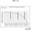
- FIG. 10 illustrates an example of the exponential function for calculating the likelihood from the correlation coefficient.
- the horizontal axis represents the correlation coefficient
- the vertical axis represents the likelihood.
- an exponential function is used that performs conversion such that the likelihood becomes a high numerical value until the correlation coefficient reaches a preset numerical value X, and the likelihood rapidly decreases when the correlation coefficient becomes equal to or less than a preset numerical value Y.
- the defective skeleton detection unit 205 detects the presence or absence of the defective skeleton based on the degree of similarity (correlation coefficient) between the cumulative twist angle and the approximate cubic curve.
- the cumulative twist angle a and the approximate cubic curve b are similar as illustrated in FIG. 9A , and the correlation coefficient is high.
- the control unit 110 determines that the skeleton information estimated in the predetermined period (from the start ts to the end te of the technique) is correct.
- the defective skeleton detection unit 205 determines that there is an incorrect portion in the skeleton information estimated in the predetermined period (from the start ts to the end te of the technique). In this case, for example, the defective skeleton detection unit 205 can perform the skeleton determination again for the periods T1 and T2 in which there is a difference between the cumulative twist angle a and the approximate cubic curve b and the correlation coefficient is low.
- FIGs. 11A and 11B are explanatory graphs of Case 2 in which the feature amount falls within the range.
- the case where the technique is the 1/2 twists for example, the case of the cumulative twist angle of the second flight phase of vault, is illustrated.
- the detection of the feature amount is basically by the same method as in Case 3 above with the single twist or more. Note that, since the number of twists is small in the 1/2 twist technique, existence of patterns in which the twist is not performed in the executed entire technique and the twist is executed around the beginning of the section in which the technique is executed and in which the twist is executed around the end of the section in which the technique is executed are considered.
- FIG. 11A is explanatory graphs when the twist technique is executed only around the beginning of the entire technique
- FIG. 11B is explanatory graphs when the twist technique is executed only around the end of the entire technique.
- the horizontal axis represents the time
- the vertical axis represents the cumulative twist angle.
- the technique is the 1/2 twists
- the period from the start ts to the end te in which the technique has been executed is divided into a plurality of divided sections, and the divided sections are caused to temporally and partially overlap each other.
- the period is divided into three divided sections, the first 2/3 divided sections and the second 2/3 divided sections are obtained, and the approximate cubic curve is calculated for each divided section.
- the approximate cubic curve is calculated in each of the first 2/3 divided sections from the start ts to time t2 of the technique and the second 2/3 divided sections from time t1 to the end te, as an example (b) illustrated in FIG. 11A .
- the likelihood in the first 2/3 divided sections becomes high, and it becomes possible to accurately detect the defective skeleton for the skeleton information in which the twist technique executed in the first half is estimated.
- the approximate cubic curve is calculated in each of the first 2/3 divided sections and the second 2/3 divided sections, as an example (b) illustrated in FIG. 11B .
- the likelihood in the second 2/3 divided sections becomes high, and it becomes possible to accurately detect the defective skeleton for the skeleton information in which the twist executed in the second half is estimated.
- FIG. 12 is a flowchart illustrating a processing example of defective skeleton detection by feature amount. The functions of FIG. 7 performed by the control unit 110 of the skeleton estimation device 100 and a processing example corresponding to each description of FIGs. 8 to 11B will be described.
- control unit 110 acquires the three-dimensional skeleton information of the gymnast from the 3D laser sensor or the like (step S1201).
- control unit 110 calculates the feature amount of each frame from the start ts to the end te of the technique (step S1202).
- control unit 110 determines the magnitude of the feature amount and proceeds to processing by magnitude (step S1203).
- the case is determined as Case 1 (step S1203: Case 1), and the processing proceeds to step S1204.
- the case is determined as Case 2 (step S1203: Case 2), and the processing proceeds to step S1205.
- the case is determined as Case 3 (step S1203: Case 3), and the processing proceeds to step S1207.
- control unit 110 calculates the maximum value and the minimum value of the feature amount during the predetermined period (the start ts to the end te of the technique) (step S1204), and proceeds to the processing of step S1209.
- control unit 110 calculates the approximate line by a multidimensional function for each of a plurality of sections stored in advance for the period up to the predetermined period (the start ts to the end te of the technique) (step S1205). Thereafter, the control unit 110 obtains the correlation coefficient between the approximate line calculated for each of the plurality of sections and the motion feature amount (step S1206), and proceeds to the processing of step S1209.
- control unit 110 calculates the approximate cubic curve from the feature amount during the predetermined period (the start ts to the end te of the technique) (step S1207). Thereafter, the control unit 110 calculates the correlation coefficient between the calculated cubic approximate curve and the feature amount (step S1208) and proceeds to the processing of step S1209.
- the control unit 110 calculates the likelihood (step S1209).
- the likelihood is calculated from the correlation coefficient between the calculated approximate line and the motion feature amount.
- the control unit 110 outputs the likelihood low with respect to the impossible move based on the feature amount (the maximum value and the minimum value of the twist angle, the description of FIG. 8 ) without using the correlation.
- control unit 110 calculates the error between the approximate line and the motion feature amount (step S 1210). Then, the control unit 110 detects the frame of the portion of the defective skeleton in the estimated skeleton information by calculating the frame with the error equal to or larger than a predetermined value (step S1211).
- control unit 110 becomes able to detect the presence or absence of the defective skeleton for the skeleton estimated in the predetermined period (the start ts to the end te of the technique). For example, CG frames K3 to K6 in FIG. 5 can be detected as the defective skeleton NG. Thereby, the control unit 110 can perform the skeleton determination again for the portion of the detected defective skeleton NG.
- the example of detecting the defective skeleton in the case where the motion feature amount is the "motion twist amount" has been described by taking the vault competition of gymnastics as an example.
- FIG. 13 (i.e., FIGs. 13A and 13B ) is explanatory graphs of detection of the defective skeleton for another feature amount.
- FIG. 13 illustrates a correlation state between the approximate line and the motion feature amount in a case where the cumulative salto angle motion feature amount of the second flight phase of vault is a "salto (vertical turn)".
- the control unit 110 calculates the approximate straight line (primary straight line) from the cumulative salto angle. Thereafter, the control unit 110 calculates the correlation coefficient between the cumulative salto angle and the approximate straight line. Thereafter, the control unit 110 calculates the likelihood from the correlation coefficient using an exponential function of a preset parameter.
- an exponential coefficient similar to that in the case of the twist illustrated in FIG. 10 can be used.
- the control unit 110 becomes able to detect the defective skeleton for the skeleton estimated based on the degree of similarity (correlation) between the cumulative salto angle and the approximate straight line.
- the cumulative salto angle a and the approximate straight line b are similar and the correlation coefficient is high, it can be determined that the estimated skeleton is correct.
- the correlation coefficient becomes low, and it becomes possible to detect the defective skeleton in which the estimated skeleton is incorrect.
- the skeleton estimation device acquires the estimation information in which a change in the skeleton in the predetermined period is estimated in units of frames, calculates the feature amount of the change in the skeleton in the predetermined period, calculates the approximate line based on the calculated feature amount, calculates the correlation state between the calculated feature amount and the calculated approximate line, and detects, as the defective skeleton, a frame portion in which estimation is abnormal in the estimation information in the predetermined period based on the correlation state.
- the feature amount corresponds to the change in the skeleton, and is, for example, a twist or a turn of a body or the like. Thereby, it becomes possible to detect a portion different from an actual move in the estimated skeleton as the defective skeleton.
- the defective skeleton is determined based on the change in the skeleton over the entire predetermined period. Therefore, it becomes possible to detect the defective skeleton in a case where the change is small only between adjacent frames so that the detection is not possible or a case where the change occurs in the entire predetermined period, as compared with detection based on a sudden change between partial adjacent frames as in an existing case.
- the skeleton estimation device becomes able to detect the defective skeleton in the estimation information of the skeleton by feature amount, for example, by different twist amount, by using a different method of detecting the defective skeleton according to the magnitude of the feature amount.
- the skeleton estimation device calculates the approximate curve by a multidimensional function from the feature amount in the predetermined period in a case where the feature amount exceeds a preset range, calculates the likelihood from the correlation coefficient between the calculated feature amount and the calculated approximate curve, and detects, as the defective skeleton, the frame with a maximum difference between the feature amount and the approximate curve in a case where the likelihood is smaller than a preset threshold.
- the skeleton estimation device calculates each of the approximate curves by a multidimensional function from the feature amount for each divided section obtained by dividing the predetermined period into a plurality of divided sections in a case where the feature amount falls within a preset range, calculates the likelihood from the correlation coefficient between the feature amount calculated in each of the divided sections and the calculated approximate curve, and detects, as the defective skeleton, the frame with a maximum difference between the feature amount and the approximate curve in a case where the likelihood is smaller than a preset threshold.
- the division may be performed such that a plurality of divided sections partially and temporally overlaps each other. Thereby, it becomes possible to accurately detect the defective skeleton for each divided section. For example, even in a case where the twist is performed only in the first half or the second half of the predetermined period, it becomes possible to accurately detect the defective skeleton for the twist estimation information by using the divided sections.
- the skeleton estimation device calculates the maximum value and the minimum value of the feature amount in the predetermined period in a case where the feature amount is less than the preset range, calculates the likelihood based on the cumulative amount of the feature amounts including the calculated maximum value and the calculated minimum value, and detects the defective skeleton based on the likelihood.
- the skeleton estimation device calculates the maximum value and the minimum value of the feature amount in the predetermined period in a case where the feature amount is less than the preset range, calculates the likelihood based on the cumulative amount of the feature amounts including the calculated maximum value and the calculated minimum value, and detects the defective skeleton based on the likelihood.
- the skeleton estimation device can estimate the skeleton again for the frame portion of the detected defective skeleton. Thereby, it becomes possible to present accurate skeleton information to the outside over the entire predetermined period.
- the above-described skeleton estimation device can be applied to a gymnastics scoring support system of a gymnastics competition in which a gymnast executes a technique.
- the gymnastics scoring support system includes the 3D laser sensor that captures an image of the gymnast, and the skeleton estimation device that includes the skeleton recognition unit that acquires an image of the three-dimensional point cloud including the distance information in units of frames, generates the depth image from the image of the three-dimensional point cloud, and recognizes the three-dimensional skeleton of the gymnast based on the training model that has been trained from the depth image in advance, the fitting unit that outputs the three-dimensional skeleton adapted to the skeleton of the gymnast as the estimation information based on the three-dimensional point cloud and the three-dimensional skeleton, and the control unit.
- the control unit has the feature amount by technique set in advance, and detects the defective skeleton in the estimation information output from the fitting unit corresponding to execution of a predetermined technique by the gymnast. Thereby, the control unit estimates the change in the skeleton of the gymnast over the predetermined period and presents the skeleton information corresponding to the technique executed in the predetermined period by the gymnast to the scoring person.
- the scoring person becomes able to perform more accurate scoring not only visually but also based on the technique of gymnastics executed by the gymnast using the skeleton information presented by the skeleton estimation device, for example, the angle of each joint or the like.
- the skeleton estimation device presents the estimation information to the scoring person of the gymnastics competition, and presents the estimation information after the skeleton is estimated again for the frame portion of the defective skeleton at the time of detecting the defective skeleton.
- the skeleton estimation device becomes able to always present the correctly estimated skeleton information to the scoring person and to improve the reliability of the estimated skeleton information presented by the skeleton estimation device.
- the embodiment it is possible to correctly detect the skeleton that changes over the entire predetermined period, and it becomes possible to detect the defective skeleton and estimate the skeleton again even in the case where there is the defective skeleton in part of the estimated skeleton information.
- the estimation of the skeleton of the embodiment is not limited to the gymnastics competition, and can be applied to skeleton estimation in various fields such as examination and monitoring of a patient in medical care.
- the skeleton estimation method described in the embodiment of the present invention may be implemented by causing a processor such as a server to execute a program prepared in advance.
- the present skeleton estimation method is recorded on a computer-readable recording medium such as a hard disk, a flexible disk, a compact disc-read only memory (CD-ROM), a digital versatile disk (DVD), a flash memory, or the like, and is read from the recording medium and executed by a computer.
- the present skeleton estimation method may be distributed via a network such as the Internet.
Landscapes
- Engineering & Computer Science (AREA)
- Health & Medical Sciences (AREA)
- Physics & Mathematics (AREA)
- Life Sciences & Earth Sciences (AREA)
- General Physics & Mathematics (AREA)
- Theoretical Computer Science (AREA)
- Computer Vision & Pattern Recognition (AREA)
- Multimedia (AREA)
- General Health & Medical Sciences (AREA)
- Dentistry (AREA)
- Molecular Biology (AREA)
- Veterinary Medicine (AREA)
- Quality & Reliability (AREA)
- Public Health (AREA)
- Animal Behavior & Ethology (AREA)
- Oral & Maxillofacial Surgery (AREA)
- Surgery (AREA)
- Biophysics (AREA)
- Pathology (AREA)
- Biomedical Technology (AREA)
- Heart & Thoracic Surgery (AREA)
- Medical Informatics (AREA)
- Optics & Photonics (AREA)
- Social Psychology (AREA)
- Psychiatry (AREA)
- Physiology (AREA)
- Human Computer Interaction (AREA)
- Image Analysis (AREA)
Applications Claiming Priority (1)
| Application Number | Priority Date | Filing Date | Title |
|---|---|---|---|
| PCT/JP2021/000107 WO2022149190A1 (ja) | 2021-01-05 | 2021-01-05 | 骨格推定装置、骨格推定方法および体操採点支援システム |
Publications (1)
| Publication Number | Publication Date |
|---|---|
| EP4276739A1 true EP4276739A1 (de) | 2023-11-15 |
Family
ID=82358123
Family Applications (1)
| Application Number | Title | Priority Date | Filing Date |
|---|---|---|---|
| EP21917418.2A Pending EP4276739A1 (de) | 2021-01-05 | 2021-01-05 | Skelettschätzvorrichtung, skelettschätzverfahren und gymnastik-bewertungsunterstützungssystem |
Country Status (5)
| Country | Link |
|---|---|
| US (1) | US20230316543A1 (de) |
| EP (1) | EP4276739A1 (de) |
| JP (1) | JP7388576B2 (de) |
| CN (1) | CN116648190A (de) |
| WO (1) | WO2022149190A1 (de) |
Family Cites Families (4)
| Publication number | Priority date | Publication date | Assignee | Title |
|---|---|---|---|---|
| JP2953413B2 (ja) | 1996-12-09 | 1999-09-27 | 日本電気株式会社 | 動作修正方法および動作修正装置 |
| JP4148281B2 (ja) | 2006-06-19 | 2008-09-10 | ソニー株式会社 | モーションキャプチャ装置及びモーションキャプチャ方法、並びにモーションキャプチャプログラム |
| JP2009015558A (ja) | 2007-07-04 | 2009-01-22 | Nippon Telegr & Teleph Corp <Ntt> | 姿勢推定装置および姿勢推定方法 |
| JP7067561B2 (ja) | 2017-09-05 | 2022-05-16 | 富士通株式会社 | 採点方法、採点プログラムおよび採点装置 |
-
2021
- 2021-01-05 JP JP2022573819A patent/JP7388576B2/ja active Active
- 2021-01-05 WO PCT/JP2021/000107 patent/WO2022149190A1/ja active Application Filing
- 2021-01-05 CN CN202180085658.5A patent/CN116648190A/zh active Pending
- 2021-01-05 EP EP21917418.2A patent/EP4276739A1/de active Pending
-
2023
- 2023-06-06 US US18/206,216 patent/US20230316543A1/en active Pending
Also Published As
| Publication number | Publication date |
|---|---|
| US20230316543A1 (en) | 2023-10-05 |
| WO2022149190A1 (ja) | 2022-07-14 |
| JPWO2022149190A1 (de) | 2022-07-14 |
| JP7388576B2 (ja) | 2023-11-29 |
| CN116648190A (zh) | 2023-08-25 |
Similar Documents
| Publication | Publication Date | Title |
|---|---|---|
| JP4991317B2 (ja) | 顔特徴点検出装置及びその方法 | |
| US11763603B2 (en) | Physical activity quantification and monitoring | |
| JP6025845B2 (ja) | オブジェクト姿勢検索装置及び方法 | |
| US8411927B2 (en) | Marker detection in X-ray images | |
| US20200397346A1 (en) | Annotation method, annotation device, storage medium, and identification system | |
| CN103310188A (zh) | 用于姿态识别的方法和设备 | |
| US11692910B2 (en) | Abnormality diagnostic device, abnormality diagnostic method, and program | |
| Lin et al. | Segmenting human motion for automated rehabilitation exercise analysis | |
| US20220222975A1 (en) | Motion recognition method, non-transitory computer-readable recording medium and information processing apparatus | |
| US11494702B2 (en) | Task estimation method and information processing apparatus | |
| EP4276739A1 (de) | Skelettschätzvorrichtung, skelettschätzverfahren und gymnastik-bewertungsunterstützungssystem | |
| US20230326251A1 (en) | Work estimation device, work estimation method, and non-transitory computer readable medium | |
| Laporte et al. | Robust tongue tracking in ultrasound images: a multi-hypothesis approach. | |
| US20230046705A1 (en) | Storage medium, determination device, and determination method | |
| US11848091B2 (en) | Motion estimation system, motion estimation method, and motion estimation program | |
| CN115937991A (zh) | 人体摔倒识别方法、装置、计算机设备及存储介质 | |
| JPWO2022149190A5 (de) | ||
| EP3869458A1 (de) | Darstellung einer ringförmigen struktur | |
| CN113470073A (zh) | 一种基于深度学习的动物中心追踪方法 | |
| CN117015802A (zh) | 用于改进无标记运动分析的方法 | |
| ZIN et al. | Feature detection and analysis of cow motion classification for predicting calving time | |
| Douvantzis et al. | Dimensionality reduction for efficient single frame hand pose estimation | |
| US20230169760A1 (en) | Computer-readable recording medium storing label change program, label change method, and information processing apparatus | |
| EP4080449A1 (de) | Medizinische bildqualitätsbeurteilung | |
| Sakai et al. | Radio Calisthenics Motion Detection and Diagnosis Using Recurrent Neural Network |
Legal Events
| Date | Code | Title | Description |
|---|---|---|---|
| STAA | Information on the status of an ep patent application or granted ep patent |
Free format text: STATUS: THE INTERNATIONAL PUBLICATION HAS BEEN MADE |
|
| PUAI | Public reference made under article 153(3) epc to a published international application that has entered the european phase |
Free format text: ORIGINAL CODE: 0009012 |
|
| STAA | Information on the status of an ep patent application or granted ep patent |
Free format text: STATUS: REQUEST FOR EXAMINATION WAS MADE |
|
| 17P | Request for examination filed |
Effective date: 20230605 |
|
| AK | Designated contracting states |
Kind code of ref document: A1 Designated state(s): AL AT BE BG CH CY CZ DE DK EE ES FI FR GB GR HR HU IE IS IT LI LT LU LV MC MK MT NL NO PL PT RO RS SE SI SK SM TR |
|
| DAV | Request for validation of the european patent (deleted) | ||
| DAX | Request for extension of the european patent (deleted) | ||
| REG | Reference to a national code |
Ref country code: DE Ref legal event code: R079 Free format text: PREVIOUS MAIN CLASS: G06T0007000000 Ipc: G06V0010980000 |