EP4276348A1 - Valve for a gas cartridge, gas cartridge for a water sprinkler and method for filling such a gas cartridge - Google Patents
Valve for a gas cartridge, gas cartridge for a water sprinkler and method for filling such a gas cartridge Download PDFInfo
- Publication number
- EP4276348A1 EP4276348A1 EP23172061.6A EP23172061A EP4276348A1 EP 4276348 A1 EP4276348 A1 EP 4276348A1 EP 23172061 A EP23172061 A EP 23172061A EP 4276348 A1 EP4276348 A1 EP 4276348A1
- Authority
- EP
- European Patent Office
- Prior art keywords
- valve
- gas
- cartridge
- opening
- valve housing
- Prior art date
- Legal status (The legal status is an assumption and is not a legal conclusion. Google has not performed a legal analysis and makes no representation as to the accuracy of the status listed.)
- Pending
Links
- XLYOFNOQVPJJNP-UHFFFAOYSA-N water Substances O XLYOFNOQVPJJNP-UHFFFAOYSA-N 0.000 title claims abstract description 27
- 238000000034 method Methods 0.000 title claims description 8
- 239000012530 fluid Substances 0.000 claims abstract description 12
- CDBYLPFSWZWCQE-UHFFFAOYSA-L Sodium Carbonate Chemical compound [Na+].[Na+].[O-]C([O-])=O CDBYLPFSWZWCQE-UHFFFAOYSA-L 0.000 claims description 34
- 238000007789 sealing Methods 0.000 description 9
- 230000004913 activation Effects 0.000 description 2
- 230000006835 compression Effects 0.000 description 2
- 238000007906 compression Methods 0.000 description 2
- 238000007599 discharging Methods 0.000 description 2
- 230000003213 activating effect Effects 0.000 description 1
- 238000003763 carbonization Methods 0.000 description 1
- 238000004891 communication Methods 0.000 description 1
- 239000003651 drinking water Substances 0.000 description 1
- 235000020188 drinking water Nutrition 0.000 description 1
- 230000009977 dual effect Effects 0.000 description 1
- 230000000694 effects Effects 0.000 description 1
- 230000007613 environmental effect Effects 0.000 description 1
- 238000000605 extraction Methods 0.000 description 1
- 238000003780 insertion Methods 0.000 description 1
- 230000037431 insertion Effects 0.000 description 1
- 230000003993 interaction Effects 0.000 description 1
- 239000007788 liquid Substances 0.000 description 1
- 230000036316 preload Effects 0.000 description 1
- 230000000284 resting effect Effects 0.000 description 1
Images


Classifications
-
- F—MECHANICAL ENGINEERING; LIGHTING; HEATING; WEAPONS; BLASTING
- F17—STORING OR DISTRIBUTING GASES OR LIQUIDS
- F17C—VESSELS FOR CONTAINING OR STORING COMPRESSED, LIQUEFIED OR SOLIDIFIED GASES; FIXED-CAPACITY GAS-HOLDERS; FILLING VESSELS WITH, OR DISCHARGING FROM VESSELS, COMPRESSED, LIQUEFIED, OR SOLIDIFIED GASES
- F17C13/00—Details of vessels or of the filling or discharging of vessels
- F17C13/04—Arrangement or mounting of valves
-
- F—MECHANICAL ENGINEERING; LIGHTING; HEATING; WEAPONS; BLASTING
- F17—STORING OR DISTRIBUTING GASES OR LIQUIDS
- F17C—VESSELS FOR CONTAINING OR STORING COMPRESSED, LIQUEFIED OR SOLIDIFIED GASES; FIXED-CAPACITY GAS-HOLDERS; FILLING VESSELS WITH, OR DISCHARGING FROM VESSELS, COMPRESSED, LIQUEFIED, OR SOLIDIFIED GASES
- F17C2201/00—Vessel construction, in particular geometry, arrangement or size
- F17C2201/01—Shape
- F17C2201/0104—Shape cylindrical
- F17C2201/0109—Shape cylindrical with exteriorly curved end-piece
-
- F—MECHANICAL ENGINEERING; LIGHTING; HEATING; WEAPONS; BLASTING
- F17—STORING OR DISTRIBUTING GASES OR LIQUIDS
- F17C—VESSELS FOR CONTAINING OR STORING COMPRESSED, LIQUEFIED OR SOLIDIFIED GASES; FIXED-CAPACITY GAS-HOLDERS; FILLING VESSELS WITH, OR DISCHARGING FROM VESSELS, COMPRESSED, LIQUEFIED, OR SOLIDIFIED GASES
- F17C2201/00—Vessel construction, in particular geometry, arrangement or size
- F17C2201/05—Size
- F17C2201/058—Size portable (<30 l)
-
- F—MECHANICAL ENGINEERING; LIGHTING; HEATING; WEAPONS; BLASTING
- F17—STORING OR DISTRIBUTING GASES OR LIQUIDS
- F17C—VESSELS FOR CONTAINING OR STORING COMPRESSED, LIQUEFIED OR SOLIDIFIED GASES; FIXED-CAPACITY GAS-HOLDERS; FILLING VESSELS WITH, OR DISCHARGING FROM VESSELS, COMPRESSED, LIQUEFIED, OR SOLIDIFIED GASES
- F17C2205/00—Vessel construction, in particular mounting arrangements, attachments or identifications means
- F17C2205/03—Fluid connections, filters, valves, closure means or other attachments
- F17C2205/0302—Fittings, valves, filters, or components in connection with the gas storage device
- F17C2205/0311—Closure means
- F17C2205/0314—Closure means breakable, e.g. with burst discs
-
- F—MECHANICAL ENGINEERING; LIGHTING; HEATING; WEAPONS; BLASTING
- F17—STORING OR DISTRIBUTING GASES OR LIQUIDS
- F17C—VESSELS FOR CONTAINING OR STORING COMPRESSED, LIQUEFIED OR SOLIDIFIED GASES; FIXED-CAPACITY GAS-HOLDERS; FILLING VESSELS WITH, OR DISCHARGING FROM VESSELS, COMPRESSED, LIQUEFIED, OR SOLIDIFIED GASES
- F17C2205/00—Vessel construction, in particular mounting arrangements, attachments or identifications means
- F17C2205/03—Fluid connections, filters, valves, closure means or other attachments
- F17C2205/0302—Fittings, valves, filters, or components in connection with the gas storage device
- F17C2205/0323—Valves
- F17C2205/0329—Valves manually actuated
-
- F—MECHANICAL ENGINEERING; LIGHTING; HEATING; WEAPONS; BLASTING
- F17—STORING OR DISTRIBUTING GASES OR LIQUIDS
- F17C—VESSELS FOR CONTAINING OR STORING COMPRESSED, LIQUEFIED OR SOLIDIFIED GASES; FIXED-CAPACITY GAS-HOLDERS; FILLING VESSELS WITH, OR DISCHARGING FROM VESSELS, COMPRESSED, LIQUEFIED, OR SOLIDIFIED GASES
- F17C2205/00—Vessel construction, in particular mounting arrangements, attachments or identifications means
- F17C2205/03—Fluid connections, filters, valves, closure means or other attachments
- F17C2205/0302—Fittings, valves, filters, or components in connection with the gas storage device
- F17C2205/0382—Constructional details of valves, regulators
-
- F—MECHANICAL ENGINEERING; LIGHTING; HEATING; WEAPONS; BLASTING
- F17—STORING OR DISTRIBUTING GASES OR LIQUIDS
- F17C—VESSELS FOR CONTAINING OR STORING COMPRESSED, LIQUEFIED OR SOLIDIFIED GASES; FIXED-CAPACITY GAS-HOLDERS; FILLING VESSELS WITH, OR DISCHARGING FROM VESSELS, COMPRESSED, LIQUEFIED, OR SOLIDIFIED GASES
- F17C2205/00—Vessel construction, in particular mounting arrangements, attachments or identifications means
- F17C2205/03—Fluid connections, filters, valves, closure means or other attachments
- F17C2205/0388—Arrangement of valves, regulators, filters
- F17C2205/0394—Arrangement of valves, regulators, filters in direct contact with the pressure vessel
-
- F—MECHANICAL ENGINEERING; LIGHTING; HEATING; WEAPONS; BLASTING
- F17—STORING OR DISTRIBUTING GASES OR LIQUIDS
- F17C—VESSELS FOR CONTAINING OR STORING COMPRESSED, LIQUEFIED OR SOLIDIFIED GASES; FIXED-CAPACITY GAS-HOLDERS; FILLING VESSELS WITH, OR DISCHARGING FROM VESSELS, COMPRESSED, LIQUEFIED, OR SOLIDIFIED GASES
- F17C2221/00—Handled fluid, in particular type of fluid
- F17C2221/01—Pure fluids
- F17C2221/013—Carbone dioxide
-
- F—MECHANICAL ENGINEERING; LIGHTING; HEATING; WEAPONS; BLASTING
- F17—STORING OR DISTRIBUTING GASES OR LIQUIDS
- F17C—VESSELS FOR CONTAINING OR STORING COMPRESSED, LIQUEFIED OR SOLIDIFIED GASES; FIXED-CAPACITY GAS-HOLDERS; FILLING VESSELS WITH, OR DISCHARGING FROM VESSELS, COMPRESSED, LIQUEFIED, OR SOLIDIFIED GASES
- F17C2223/00—Handled fluid before transfer, i.e. state of fluid when stored in the vessel or before transfer from the vessel
- F17C2223/01—Handled fluid before transfer, i.e. state of fluid when stored in the vessel or before transfer from the vessel characterised by the phase
- F17C2223/0107—Single phase
- F17C2223/0123—Single phase gaseous, e.g. CNG, GNC
-
- F—MECHANICAL ENGINEERING; LIGHTING; HEATING; WEAPONS; BLASTING
- F17—STORING OR DISTRIBUTING GASES OR LIQUIDS
- F17C—VESSELS FOR CONTAINING OR STORING COMPRESSED, LIQUEFIED OR SOLIDIFIED GASES; FIXED-CAPACITY GAS-HOLDERS; FILLING VESSELS WITH, OR DISCHARGING FROM VESSELS, COMPRESSED, LIQUEFIED, OR SOLIDIFIED GASES
- F17C2223/00—Handled fluid before transfer, i.e. state of fluid when stored in the vessel or before transfer from the vessel
- F17C2223/03—Handled fluid before transfer, i.e. state of fluid when stored in the vessel or before transfer from the vessel characterised by the pressure level
- F17C2223/036—Very high pressure (>80 bar)
-
- F—MECHANICAL ENGINEERING; LIGHTING; HEATING; WEAPONS; BLASTING
- F17—STORING OR DISTRIBUTING GASES OR LIQUIDS
- F17C—VESSELS FOR CONTAINING OR STORING COMPRESSED, LIQUEFIED OR SOLIDIFIED GASES; FIXED-CAPACITY GAS-HOLDERS; FILLING VESSELS WITH, OR DISCHARGING FROM VESSELS, COMPRESSED, LIQUEFIED, OR SOLIDIFIED GASES
- F17C2270/00—Applications
- F17C2270/07—Applications for household use
- F17C2270/0736—Capsules, e.g. CO2
Definitions
- the present invention relates to a valve for selectively closing and selectively opening a gas cartridge for a soda maker, the valve being adapted to retain a gas in the gas cartridge when it is closed and to provide fluid connection to the gas cartridge when it is opened, wherein the valve comprises a valve housing having a cartridge connection opening aligned along a longitudinal axis of the valve so that gas can flow into and out of the cartridge in the direction of the longitudinal axis.
- valves are used on gas cartridges, in particular CO 2 cartridges, for soda makers.
- Such soda makers are also referred to as carbonizers and typically have a gas cartridge connection through which the gas cartridge or the valve of the gas cartridge can be connected to the water soda maker.
- the valve of the gas cartridge can then be optionally opened via an actuating device of the water soda maker in order to remove gas, in particular CO 2 , from the gas cartridge and supply this to a container with liquid to be carbonated, for example drinking water.
- Such a valve is known for a gas cartridge.
- the known valve includes a cartridge connection opening through which gas can be filled into a receiving space of the gas cartridge and removed from it.
- This cartridge connection opening is arranged along a direction parallel to the longitudinal axis, so that gas can flow into and out of the receiving space of the gas cartridge in the direction of the longitudinal axis.
- at least one external connection opening is provided in this valve, which opens laterally to the longitudinal axis, so that the gas can flow out of the valve in a direction perpendicular to the longitudinal axis when it is removed from the soda maker.
- the object of the present invention is to provide a valve or a gas cartridge in which lateral recoil forces are reduced.
- the valve according to the invention is designed to be selectively closed and selectively opened, so that gas can be removed from the gas cartridge as well as the gas cartridge can be filled with gas optionally.
- the valve When the valve is closed, the gas can be held in the gas cartridge.
- a fluid connection to the gas cartridge, in particular a receiving space of the gas cartridge is provided so that removal or filling can take place.
- the gas can be removed from the gas cartridge via the outlet opening of the at least one gas outlet element movably arranged on the valve housing take place when the gas outlet element is in the removal position.
- the outlet opening is arranged on the outside and oriented in such a way that gas flows out of the valve in a direction parallel to the longitudinal axis of the valve housing, so that any recoil forces caused by the outflow act parallel to the longitudinal direction. In this way, recoil forces perpendicular to the longitudinal direction can be reduced or avoided.
- the gas cartridge with the valve is arranged upright in a water soda maker, lateral forces when removing gas are reduced.
- the outlet opening of the gas outlet element is arranged in the removal position such that the gas can escape in a direction that points away from the cartridge connection opening.
- the valve comprises a plurality of gas outlet elements, which are arranged on the valve housing to be movable between a rest position and a removal position and have an outlet opening, wherein the plurality of gas outlet elements protrude from the valve housing in the removal position, so that the outlet opening is arranged externally and along a direction parallel to the longitudinal axis such that gas can flow out of the valve in the direction parallel to the longitudinal axis.
- the effective cross section available for the gas to flow out can be increased. For example, two, three, four, five or six gas outlet elements can be provided. If an even number of gas outlet elements is provided, the gas outlet elements are preferably arranged diametrically opposite one another.
- the at least one gas outlet element is arranged in the rest position within an outer contour of the valve housing in such a way that it does not protrude from the valve housing.
- Such a configuration offers the advantage that the at least one gas outlet element does not protrude from the valve housing in the rest position and thereby allows the valve to be connected can be simplified with a gas cartridge connection of a water soda maker.
- insertion into gas cartridge connections can be simplified in which the valve or gas cartridge is inserted by moving the valve in the direction of the longitudinal axis of the valve. An obstruction to this movement by gas outlet elements protruding from the valve housing can be prevented.
- the outlet opening is arranged inside the valve housing in the rest position. In the rest position, the outlet opening is protected from environmental influences. An outflow of gas through the outlet opening can be prevented in the rest position.
- the outlet opening is covered in the rest position, in particular by the valve housing, so that the gas outlet element can be moved from the rest position into the removal position by an excess pressure present in an interior of the valve housing.
- gas can be prevented from flowing out through the outlet opening.
- the gas can cause excess pressure in the interior of the valve housing, which pushes the gas outlet element from the rest position towards the removal position.
- the excess pressure can be caused by an actuation of the valve, so that as a result of the actuation the pressure in the interior of the valve housing increases, as a result of this increase in pressure the gas outlet element is transferred to its removal position and the gas can then flow out of the valve in the removal position of the gas outlet element.
- the gas outlet element can be moved between the rest position and the removal position in a direction arranged obliquely, in particular perpendicularly, to the longitudinal axis.
- the at least one gas outlet element is preferably linearly movable. If the valve housing has a substantially cylindrical shape, the at least one gas outlet element is preferably movable in a radial direction.
- the at least one gas outlet element is preferably arranged in a guide, for example a guide bore, of the valve housing.
- the gas outlet element is arranged in the guide so that it can be moved linearly, in particular displaceably.
- the guide is preferably arranged in a radial direction.
- the gas outlet element has a stop, in particular designed as a projection, which limits the movement of the gas outlet element in the direction of the removal position.
- the stop can stop a movement of the gas outlet element, in particular due to an overpressure in the interior of the valve housing.
- the stop of the gas outlet element is configured to be in contact with a stop surface in an interior of the valve housing in a maximum extended removal position.
- the interaction of the stop of the gas outlet element and the stop surface defines an end position beyond which the gas outlet element cannot be moved out of the valve housing.
- the gas outlet element comprises a gas channel connected to the outlet opening, which has an angled course, in particular by 90°.
- the gas channel within the gas outlet element preferably runs from the outlet opening initially in a direction parallel to the longitudinal axis of the valve and bends at a bend point, in particular at 90 °, so that the channel has a course after the bend point that is oblique, in particular is arranged perpendicular to the longitudinal axis of the valve.
- An inner opening of the gas channel arranged within the valve housing is preferably in fluid communication with an interior of the valve housing.
- the at least one gas outlet element has an external actuation surface arranged obliquely to the longitudinal axis, which can be actuated from an outside of the valve housing, for example when the valve is removed from a gas cartridge connection of a water soda maker, in order to move the gas outlet element in To spend in the direction of the resting position.
- the actuation surface can be designed in the manner of a chamfer and can be located on an, in particular external, edge of the gas outlet element.
- the actuation surface is preferably arranged on a side of the gas outlet element that lies opposite the outlet opening, in particular in a direction parallel to the longitudinal direction of the valve housing.
- the gas outlet element is biased in the direction of the rest position, in particular by a gas outlet spring element.
- the at least one gas outlet element can have an internal actuation surface arranged obliquely to the longitudinal axis and a plunger movable along the longitudinal axis, the plunger being movably mounted in the valve housing in such a way that a movement of the plunger in the direction of the cartridge connection opening results in contact between the plunger and the internal actuation surface and thereby moves the gas outlet element in the direction of the removal position.
- the plunger can be biased by a spring element in a direction away from the cartridge connection opening.
- a, in particular annular, retaining element is arranged on the valve housing, via which the valve can be fixed in a gas cartridge connection of a water soda maker.
- the retaining element preferably protrudes from the valve housing in a direction oblique, in particular perpendicular, to the longitudinal axis of the valve housing. If the valve is inserted into the gas cartridge connection of the soda maker, for example by a movement in the direction of the longitudinal axis, the retaining element can be engaged behind by a holding element of the soda maker and thereby the valve or the gas cartridge can be fixed to the soda maker.
- a pressure relief valve in particular comprising a rupture disk, is arranged on the valve housing, which is configured to allow excess pressure existing in the area of the cartridge connection opening to escape.
- the rupture disk is preferably configured in such a way that it bursts at a predetermined excess pressure in the area. When the rupture disk ruptures, a connection can be established between the cartridge connection opening and the environment.
- the pressure relief valve preferably comprises an external pressure relief outlet opening which opens laterally to the longitudinal axis.
- the valve has a cartridge closure element which is biased into a closed position, in which the cartridge closure element closes a passage between the outlet opening of the at least one gas outlet element and the cartridge connection opening, the cartridge closure element can be moved by an actuating element of the valve in the direction of an open position, in which the passage between the outlet opening and the cartridge connection opening is opened for discharging gas. That is preferred Actuating element of the valve can be moved along the longitudinal axis. The actuating element can be actuated by an activation element of a soda maker that interacts with the actuating element, for example by an activation pin, when the valve or the gas cartridge is connected to a gas cartridge connection of the water soda maker.
- the cartridge closure element is preferably prestressed in the direction of the closed position by means of a first spring element.
- the first spring element can be designed as a helical spring, preferably as a helical compression spring.
- the aforementioned open position of the cartridge closure element can also be used to open a passage between the cartridge connection opening and any filling opening of the valve housing for introducing gas into the gas cartridge.
- the valve housing has a filling opening on a side opposite the cartridge connection opening, through which gas can flow into the valve in the direction of the longitudinal axis.
- the filling opening is thus aligned along a longitudinal axis of the valve.
- the filling opening offers the advantage that it is not necessary to fill the gas cartridge via the outlet opening of the at least one gas outlet element. It is therefore not necessary to move the at least one outlet element into the removal position in order to fill the gas cartridge. Rather, the outlet element for filling the gas cartridge can be arranged in the rest position.
- the valve housing has a filling opening on a side opposite the cartridge connection opening, through which gas can flow into the valve in the direction of the longitudinal axis, the actuating element having the filling opening.
- the actuating element has a dual function: on the one hand, it can be used to actuate the gas extraction, in particular pressed in, and it provides a filling opening for filling the gas cartridge. It is therefore possible to apply both a pressure force that activates the removal of gas in the direction of the longitudinal axis - in particular through an activating element of a water soda maker - and also to introduce gas into the valve in the direction of the longitudinal axis during filling.
- the valve has an inlet closure element, which is biased by a second spring element into a closed position, in which the inlet closure element closes the filling opening, the second spring element being designed such that the inlet -Closure element can be brought into an open position by applying a predetermined gas pressure to the filling opening, in which the filling opening is open to introduce gas.
- the prestressed inlet closure element therefore provides a partial filling valve in the manner of a check valve, which holds gas in the valve and admits gas if there is a gas pressure at the filling opening that exceeds the predetermined gas pressure.
- the second spring element can be designed as a helical spring, preferably as a helical compression spring.
- the valve additionally has a cartridge closure element which is biased into a closed position in which the cartridge closure element closes a passage between the filling opening and the cartridge connection opening, the cartridge closure element passing through the inlet closure element of the valve can be moved in the direction of an open position, in which the passage between the filling opening and the cartridge connection opening is opened for introducing gas.
- the cartridge closure element can also be moved into its open position. In this way, a fluid connection can be established between the inlet opening and the cartridge connection opening, via which the gas cartridge can be filled.
- the cartridge closure element is preferably the same cartridge closure element which, in the closed position, closes a passage between the outlet opening of the at least one gas outlet element and the cartridge connection opening.
- a gas cartridge is also proposed for connecting to a gas cartridge connection of a water soda maker with a valve described above.
- the gas cartridge can achieve the same advantages and effects that have already been explained in connection with the valve according to the invention.
- the invention further relates to a method for filling a gas cartridge described above, wherein the valve housing has a filling opening on a side opposite the cartridge connection opening, via which gas is introduced into the valve in the direction of the longitudinal axis.
- the method allows a gas cartridge to be filled by supplying gas along the longitudinal axis of the valve.
- a gas cartridge filled with gas is provided, from which gas can be removed via the outlet opening of the at least one gas outlet element in a direction parallel to the longitudinal axis of the valve. In this way, when gas is removed, recoil forces perpendicular to the longitudinal direction can be reduced or avoided.
- the valve has an inlet closure element, which is biased by a spring element into a closed position, in which the inlet closure element closes the filling opening, a predetermined gas pressure being applied to the filling opening in order to to move the inlet closure element into an open position.
- the prestressed inlet closure element thus forms a type of check valve, which is opened when the predetermined gas pressure at the inlet opening is exceeded. In the open position of the inlet closure element, gas can then be introduced into the valve through the inlet opening.
- a fluid connection between the outlet opening of the at least one gas outlet element and the environment is sealed.
- one or more sealing elements can rest against an outer contour of the valve housing, which seal the outlet opening.
- pressure can be exerted on the at least one gas outlet element from the outside in order to bring it into its rest position.
- a gas cartridge 1 is shown according to an exemplary embodiment of the invention.
- the gas cartridge 1 is configured to be connected to a gas cartridge connection of a water soda maker.
- the gas cartridge 1 comprises a receiving space 2 with an opening at which a valve 10 according to the invention for selectively closing and selectively opening the gas cartridge 1 is arranged.
- a valve 10 according to the invention for selectively closing and selectively opening the gas cartridge 1 is arranged.
- a gas can be held in the gas cartridge 1 and in the open position, a fluid connection can be provided to introduce gas into or remove gas from the gas cartridge 1.
- the Fig. 1 shows the area of the gas cartridge 1, which includes the valve 1.
- the gas cartridge 1 is shown in an upright position. In such an upright position, the gas cartridge 1 can be connected to the corresponding gas cartridge connection in a water soda maker.
- FIG. 2 to 7 show an exemplary embodiment of a valve 10 for selectively closing and selectively opening a gas cartridge 1 for a water soda maker, which is shown in the gas cartridge 1 Fig. 1 can be used.
- the valve 10 is configured to maintain a gas in the gas cartridge 1 when it is closed and to provide fluid connection to the gas cartridge 1 when it is open.
- the valve 10 includes a valve housing 11 which has a cartridge connection opening 15 which is aligned along a longitudinal axis L of the valve 10, so that gas can flow into the gas cartridge 1 in the direction of the longitudinal axis L and flow out of the gas cartridge 1.
- the valve housing 11 is connected to an annular retaining element 14, via which the valve 10 can be fixed in a gas cartridge connection of a water soda maker.
- the retaining element 14 can be gripped behind by a suitable holding element of the water soda maker.
- the retaining element 14 is attached to the outside of the valve housing 11.
- a seal 20, here a sealing ring, is provided between the retaining element 14 and the valve housing 11.
- the retaining element 14 can be arranged between a projection of the valve housing 11 and a container housing of the gas cartridge 1. Alternatively, the retaining element 14 can be formed in one piece with the valve housing 11.
- a pressure relief valve 13 which includes a rupture disk 19, is arranged on the valve housing 11.
- the pressure relief valve 13 can allow excess pressure existing in the area of the cartridge connection opening to escape by causing the rupture disk 19 to burst.
- the valve 10 comprises several, here two, gas outlet elements 12, which are each arranged on the valve housing 11 to be movable between a rest position and a removal position and each have an outlet opening 16.
- a gas channel 31 is formed within the gas outlet element 16 and has an angled course starting from the interior of the valve housing 11 up to the outlet opening 16.
- the representations in Fig. 1 to 6 show the gas elements 12 in a rest position, in which the gas outlet elements 12 are arranged within the valve housing 11 in such a way that they do not protrude from the valve housing 11. This rest position is therefore suitable for inserting the valve 10 into a gas cartridge connection of a water soda maker in order to connect the valve 10 to it.
- the outlet opening 16 is arranged on the inside within the valve housing 11.
- a wall of the valve housing 11 covers the outlet opening 16, so that gas cannot escape through the outlet opening 16 if there is excess pressure in the interior of the valve housing.
- the entire gas outlet element 12 is moved out of the valve housing 11 as a result of an overpressure in the interior of the valve housing 11, starting from the rest position, so that the respective gas outlet element 12 protrudes from the valve housing 11.
- the gas outlet elements 12 are mounted in guides in the valve housing 11, which are arranged obliquely, in particular perpendicularly, to the longitudinal axis L of the valve 10.
- the gas outlet elements 12 each have a stop 32 which limits the movement of the respective gas outlet element in the direction of the removal position.
- the stop 32 is designed as a projection.
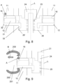
- FIG. 8 shows a gas outlet element 12 in the removal position on the left and a gas outlet element 12 in the rest position on the right.
- the gas outlet element 12 protrudes from the valve housing 11, so that the outlet opening 16 is arranged on the outside.
- the outlet opening 16 is further arranged along a direction parallel to the longitudinal axis L such that gas can flow out of the valve in the direction parallel to the longitudinal axis L, see arrow A.
- the stop 32 of the left gas outlet element 12 is in contact with a stop surface 26 'in the interior of the valve housing 11.
- this stop surface 26' is provided by an insert 26 in the interior of the valve housing 11, but can alternatively also be provided by an inner wall of the valve housing 11 itself.
- the removal position shown on the left represents a maximum extended removal position of the gas outlet element 12.
- An external actuation surface 30 arranged obliquely to the longitudinal axis L is arranged on the gas outlet element 12.
- This actuation surface 30 is designed in the manner of a chamfer and can be actuated from outside the valve 10 in order to move the gas outlet element 12 in the direction of the rest position, for example when the valve 10 is removed from a gas cartridge connection of a water soda maker, i.e. to press it into the valve housing 11 .
- the valve 10 further comprises a cartridge closure element 28, which is in an in Fig. 6 shown closed position is biased, in which the cartridge closure element 28 closes a passage between the outlet openings 16 of the gas outlet elements 12 and the cartridge connection opening 15.
- the preload is caused by a spring element 29.
- the cartridge closure element 28 can be moved against the bias by an actuating element 21 of the valve 10 in the direction of an open position, in which the passage between the outlet opening 16 and the cartridge connection opening 15 is open for discharging gas.
- the actuating element 21 is arranged externally on a side of the valve 10 opposite the cartridge connection opening 15 and can be moved in the direction of the longitudinal axis L in order to let gas out of the valve 10.
- the actuating element 21 is coupled to the cartridge closure element 28 via an inlet closure element 24 in such a way that a compressive force can be transmitted to the cartridge closure element 28.
- the inlet closure element 24 closes a filling opening 17 which is arranged in the actuating element 21.
- the filling opening is configured so that gas can flow into the valve 10 in the direction of the longitudinal axis L, provided that the inlet closure element 24 releases it.
- the inlet closure element 24 is inserted into the inlet by a spring element 25 Fig. 6 shown closed position biased, in which the inlet closure element 24 closes the filling opening.
- the spring element 25 is configured in such a way that the inlet closure element 24 can be moved into an open position by applying a predetermined gas pressure to the filling opening 17, in which the filling opening 17 is opened to introduce gas.
- gas can be introduced through the filling opening 17 into the interior of the valve housing 11 and then passed through the passage in the insert 26 in the direction of the cartridge connection opening 15.
- a detailed representation of a gas outlet element 12 of a valve 10 is shown, which is connected to a gas cartridge connection of a water soda maker.
- the gas cartridge connection includes a sealing device 200, 200', which rests on the outer contour of the valve 10 and seals an area around the outlet opening 16.
- the sealing device has an upper sealing section 200 which seals above the outlet opening 16 and a lower sealing section 200 'which seals below the outlet opening 16.
- a sealed space 201 is thus created in the space between the two sealing sections 200, 200', into which the gas flowing out of the outlet opening 16 parallel to the longitudinal direction L is received.
- This sealed space 201 can be designed in such a way that the gas is discharged in a direction oblique to the longitudinal axis L, see arrow B.
- the gas can then be conducted, for example via a line, to a carbonization device of the water soda maker, via which the gas is in a container filled with water can be introduced.
- the representations in 10 and 11 show states that occur when filling the in Fig. 1 shown gas cartridge 1 can be taken via the filling opening 17 on the side of the valve 10 opposite the cartridge connection opening 15 in order to seal a fluid connection between the outlet opening 16 of the gas outlet elements 12 and the environment. This is necessary in order to prevent unwanted escape of the gas via the outlet openings 16 when gas is introduced via the filling opening 17. Rather, the gas introduced into the valve 10 via the filling opening 17 can then be guided into the receiving space of the gas cartridge 1 via the cartridge connection opening 15.
- the gas outlet elements 12 are fixed in their rest position via a locking element 300.
- the locking element 300 can be arranged on the outer contour of the valve housing 11 in such a way that undesirable extension of the gas outlet element 12 is prevented.
- the gas outlet elements 12 can be either in their rest position or - as shown - in the removal position.
- a sealing element 301 is arranged on the outer contour of the valve housing 11, which seals the area around the outlet opening 16 from the environment.
Landscapes
- Engineering & Computer Science (AREA)
- Mechanical Engineering (AREA)
- General Engineering & Computer Science (AREA)
- Filling Or Discharging Of Gas Storage Vessels (AREA)
Abstract
Die vorliegende Erfindung betrifft ein Ventil (10) zum wahlweisen Schließen und wahlweisen Öffnen einer Gaskartusche (1) für einen Wassersprudler,wobei das Ventil (10) dazu eingerichtet ist, ein Gas in der Gaskartusche (1) zu halten, wenn es geschlossen ist und eine Fluidverbindung zur Gaskartusche (1) bereitzustellen, wenn es geöffnet ist,wobei das Ventil (10) ein Ventilgehäuse (11) umfasst, das eine Kartuschenanschlussöffnung (15) aufweist, die entlang einer Längsachse (L) des Ventils (10) ausgerichtet ist, so dass Gas in Richtung der Längsachse (L) in die Gaskartusche (1) einströmen und aus der Gaskartusche (L) ausströmen kann,gekennzeichnet durchmindestens ein Gasauslasselement (12), welches an dem Ventilgehäuse (11) zwischen einer Ruhestellung und einer Entnahmestellung bewegbar angeordnet ist und eine Auslassöffnung (16) aufweist,wobei das mindestens eine Gasauslasselement (12) in der Entnahmestellung aus dem Ventilgehäuse (11) hervorsteht, so dass die Auslassöffnung (16) außenliegend und derart entlang einer Richtung parallel zu der Längsachse (L) angeordnet ist, dass Gas aus dem Ventil (10) in der Richtung parallel zur Längsachse (L) ausströmen kann.The present invention relates to a valve (10) for selectively closing and selectively opening a gas cartridge (1) for a water carbonator, wherein the valve (10) is designed to hold a gas in the gas cartridge (1) when it is closed and to provide a fluid connection to the gas cartridge (1) when it is opened, wherein the valve (10) comprises a valve housing (11) having a cartridge connection opening (15) which is aligned along a longitudinal axis (L) of the valve (10) so that gas can flow into the gas cartridge (1) and out of the gas cartridge (L) in the direction of the longitudinal axis (L), characterized by at least one gas outlet element (12) which is arranged on the valve housing (11) so as to be movable between a rest position and a removal position and has an outlet opening (16), wherein the at least one gas outlet element (12) in the removal position from the valve housing (11) protrudes so that the outlet opening (16) is arranged externally and along a direction parallel to the longitudinal axis (L) such that gas can flow out of the valve (10) in the direction parallel to the longitudinal axis (L).
Description
Die vorliegende Erfindung betrifft ein Ventil zum wahlweisen Schließen und wahlweisen Öffnen einer Gaskartusche für einen Wassersprudler, wobei das Ventil dazu eingerichtet ist, ein Gas in der Gaskartusche zu halten, wenn es geschlossen ist und eine Fluidverbindung zur Gaskartusche bereitzustellen, wenn es geöffnet ist, wobei das Ventil ein Ventilgehäuse umfasst, das eine Kartuschenanschlussöffnung aufweist, die entlang einer Längsachse des Ventils ausgerichtet ist, so dass Gas in Richtung der Längsachse in die Kartusche einströmen und aus der Kartusche ausströmen kann.The present invention relates to a valve for selectively closing and selectively opening a gas cartridge for a soda maker, the valve being adapted to retain a gas in the gas cartridge when it is closed and to provide fluid connection to the gas cartridge when it is opened, wherein the valve comprises a valve housing having a cartridge connection opening aligned along a longitudinal axis of the valve so that gas can flow into and out of the cartridge in the direction of the longitudinal axis.
Derartige Ventile kommen zur Anwendung an Gaskartuschen, insbesondere CO2-Kartuschen, für Wassersprudler. Solche Wassersprudler werden auch als Karbonisierer bezeichnet und weisen typischerweise einen Gaskartuschenanschluss auf, über welchem die Gaskartusche, bzw. das Ventil der Gaskartusche, mit dem Wassersprudler verbunden werden kann. Über eine Betätigungseinrichtung des Wassersprudler kann das Ventil der Gaskartusche dann wahlweise geöffnet werden, um der Gaskartusche Gas, insbesondere CO2, zu entnehmen und dieses einem Behälter mit zu karbonisierender Flüssigkeit, beispielsweise Trinkwasser, zuzuführen.Such valves are used on gas cartridges, in particular CO 2 cartridges, for soda makers. Such soda makers are also referred to as carbonizers and typically have a gas cartridge connection through which the gas cartridge or the valve of the gas cartridge can be connected to the water soda maker. The valve of the gas cartridge can then be optionally opened via an actuating device of the water soda maker in order to remove gas, in particular CO 2 , from the gas cartridge and supply this to a container with liquid to be carbonated, for example drinking water.
Aus der
Die Aufgabe der vorliegenden Erfindung ist es, ein Ventil bzw. eine Gaskartusche anzugeben, bei welcher seitliche Rückstoßkräfte verringert werden.The object of the present invention is to provide a valve or a gas cartridge in which lateral recoil forces are reduced.
Zur Lösung der Aufgabe wird ein Ventil zum wahlweisen Schließen und wahlweisen Öffnen einer Gaskartusche für einen Wassersprudler vorgeschlagen,
- wobei das Ventil dazu eingerichtet ist, ein Gas in der Gaskartusche zu halten, wenn es geschlossen ist und eine Fluidverbindung zur Gaskartusche bereitzustellen, wenn es geöffnet ist,
- wobei das Ventil ein Ventilgehäuse umfasst, das eine Kartuschenanschlussöffnung aufweist, die entlang einer Längsachse des Ventils ausgerichtet ist, so dass Gas in Richtung der Längsachse in die Gaskartusche einströmen und aus der Gaskartusche ausströmen kann,
- mit mindestens einem Gasauslasselement, welches an dem Ventilgehäuse zwischen einer Ruhestellung und einer Entnahmestellung bewegbar angeordnet ist und eine Auslassöffnung aufweist,
- wobei das mindestens eine Gasauslasselement in der Entnahmestellung aus dem Ventilgehäuse hervorsteht, so dass die Auslassöffnung außenliegend und derart entlang einer Richtung parallel zu der Längsachse angeordnet ist, dass Gas aus dem Ventil in der Richtung parallel zur Längsachse ausströmen kann.
- wherein the valve is adapted to retain a gas in the gas cartridge when it is closed and to provide fluid connection to the gas cartridge when it is open,
- wherein the valve comprises a valve housing that has a cartridge connection opening that is aligned along a longitudinal axis of the valve so that gas can flow into the gas cartridge and flow out of the gas cartridge in the direction of the longitudinal axis,
- with at least one gas outlet element which is movably arranged on the valve housing between a rest position and a removal position and has an outlet opening,
- wherein the at least one gas outlet element protrudes from the valve housing in the removal position, so that the outlet opening is arranged on the outside and along a direction parallel to the longitudinal axis in such a way that gas can flow out of the valve in the direction parallel to the longitudinal axis.
Das erfindungsgemäße Ventil ist dazu eingerichtet wahlweise geschlossen und wahlweise geöffnet zu werden, so dass eine Entnahme von Gas aus der Gaskartusche sowie auch ein Befüllen der Gaskartusche mit Gas wahlweise vorgenommen werden kann. Im geschlossenen Zustand des Ventils kann das Gas in der Gaskartusche gehalten werden. Wenn das Ventil geöffnet ist, wird eine Fluidverbindung zu der Gaskartusche, insbesondere einem Aufnahmeraum der Gaskartusche, bereitgestellt so dass die Entnahme bzw. das Befüllen erfolgen kann. Über die Auslassöffnung des bewegbar an dem Ventilgehäuse angeordneten, mindestens einen Gasauslasselement kann die Entnahme des Gases aus der Gaskartusche erfolgen, wenn sich das Gasauslasselement in der Entnahmestellung befindet. In dieser Entnahmestellung ist die Auslassöffnung außenliegend angeordnet und derart orientiert, dass Gas aus dem Ventil in einer Richtung parallel zu der Längsachse des Ventilgehäuses ausströmt, so dass etwaige durch das Ausströmen hervorgerufene Rückstoßkräfte parallel zu der Längsrichtung wirken. Auf diese Weise können Rückstoßkräfte senkrecht zu der Längsrichtung verringert bzw. vermieden werden. Insofern werden bei aufrechter Anordnung der Gaskartusche mit dem Ventil in einem Wassersprudler seitliche Kräfte bei der Entnahme von Gas verringert.The valve according to the invention is designed to be selectively closed and selectively opened, so that gas can be removed from the gas cartridge as well as the gas cartridge can be filled with gas optionally. When the valve is closed, the gas can be held in the gas cartridge. When the valve is opened, a fluid connection to the gas cartridge, in particular a receiving space of the gas cartridge, is provided so that removal or filling can take place. The gas can be removed from the gas cartridge via the outlet opening of the at least one gas outlet element movably arranged on the valve housing take place when the gas outlet element is in the removal position. In this removal position, the outlet opening is arranged on the outside and oriented in such a way that gas flows out of the valve in a direction parallel to the longitudinal axis of the valve housing, so that any recoil forces caused by the outflow act parallel to the longitudinal direction. In this way, recoil forces perpendicular to the longitudinal direction can be reduced or avoided. In this respect, when the gas cartridge with the valve is arranged upright in a water soda maker, lateral forces when removing gas are reduced.
Bevorzugt ist die Auslassöffnung des Gasauslasselements in der Entnahmestellung derart angeordnet, dass das Gas in einer Richtung entweichen kann, die von der Kartuschenanschlussöffnung wegweist.Preferably, the outlet opening of the gas outlet element is arranged in the removal position such that the gas can escape in a direction that points away from the cartridge connection opening.
Gemäß einer vorteilhaften Ausgestaltung der Erfindung ist vorgesehen, dass das Ventil mehrere Gasauslasselemente umfasst, welche an dem Ventilgehäuse zwischen einer Ruhestellung und einer Entnahmestellung bewegbar angeordnet sind und eine Auslassöffnung aufweisen,
wobei die mehreren Gasauslasselemente in der Entnahmestellung aus dem Ventilgehäuse hervorstehen, so dass die Auslassöffnung außenliegend und derart entlang einer Richtung parallel zu der Längsachse angeordnet ist, dass Gas aus dem Ventil in der Richtung parallel zur Längsachse ausströmen kann. Durch das Vorsehen mehrerer Gasauslasselemente kann der effektive für das Ausströmen des Gases bereitstehende Querschnitt vergrößert werden. Beispielsweise können zwei, drei, vier, fünf oder sechs Gasauslasselemente vorgesehen sein. Sofern eine gerade Anzahl an Gasauslasselementen vorgesehen ist, sind die Gasauslasselemente bevorzugt diametral gegenüberliegend angeordnet.According to an advantageous embodiment of the invention, it is provided that the valve comprises a plurality of gas outlet elements, which are arranged on the valve housing to be movable between a rest position and a removal position and have an outlet opening,
wherein the plurality of gas outlet elements protrude from the valve housing in the removal position, so that the outlet opening is arranged externally and along a direction parallel to the longitudinal axis such that gas can flow out of the valve in the direction parallel to the longitudinal axis. By providing several gas outlet elements, the effective cross section available for the gas to flow out can be increased. For example, two, three, four, five or six gas outlet elements can be provided. If an even number of gas outlet elements is provided, the gas outlet elements are preferably arranged diametrically opposite one another.
Auch wenn in den nachfolgend erläuterten vorteilhaften Ausgestaltungen Bezug auf mindestens ein Gasauslasselement genommen wird, so umfassen diese Ausgestaltungen sowohl die Alternative, dass genau ein Gasauslasselement vorhanden ist, als auch Alternativen mit mehreren Gasauslasselementen.Even if reference is made to at least one gas outlet element in the advantageous embodiments explained below, these embodiments include both the alternative that exactly one gas outlet element is present and alternatives with several gas outlet elements.
Gemäß einer vorteilhaften Ausgestaltung der Erfindung ist vorgesehen, dass das mindestens eine Gasauslasselement in der Ruhestellung derart innerhalb einer Außenkontur des Ventilgehäuses angeordnet ist, dass es nicht aus dem Ventilgehäuse hervorsteht. Eine derartige Ausgestaltung bietet den Vorteil, dass das mindestens eine Gasauslasselement in der Ruhestellung nicht aus dem Ventilgehäuse hervorsteht und dadurch das Verbinden des Ventils mit einem Gaskartuschenanschluss eines Wassersprudlers vereinfacht werden kann. Insbesondere kann das Einsetzen in solche Gaskartuschenanschlüsse vereinfacht werden, bei denen das Einsetzen des Ventils bzw. der Gaskartusche durch eine Bewegung des Ventils in Richtung der Längsachse des Ventils erfolgt. Eine Behinderung dieser Bewegung durch aus dem Ventilgehäuse hervorstehende Gasauslasselemente kann unterbunden werden.According to an advantageous embodiment of the invention, it is provided that the at least one gas outlet element is arranged in the rest position within an outer contour of the valve housing in such a way that it does not protrude from the valve housing. Such a configuration offers the advantage that the at least one gas outlet element does not protrude from the valve housing in the rest position and thereby allows the valve to be connected can be simplified with a gas cartridge connection of a water soda maker. In particular, insertion into gas cartridge connections can be simplified in which the valve or gas cartridge is inserted by moving the valve in the direction of the longitudinal axis of the valve. An obstruction to this movement by gas outlet elements protruding from the valve housing can be prevented.
Gemäß einer vorteilhaften Ausgestaltung der Erfindung ist vorgesehen, dass die Auslassöffnung in der Ruhestellung innenliegend innerhalb des Ventilgehäuses angeordnet ist. In der Ruhestellung ist die Auslassöffnung vor Umwelteinflüssen geschützt angeordnet. Ein Ausströmen von Gas durch die Auslassöffnung kann in der Ruhestellung verhindert werden.According to an advantageous embodiment of the invention, it is provided that the outlet opening is arranged inside the valve housing in the rest position. In the rest position, the outlet opening is protected from environmental influences. An outflow of gas through the outlet opening can be prevented in the rest position.
Gemäß einer vorteilhaften Ausgestaltung der Erfindung ist vorgesehen, dass die Auslassöffnung in der Ruhestellung, insbesondere durch das Ventilgehäuse abgedeckt ist, so dass das Gasauslasselement durch einen in einem Innenraum des Ventilgehäuses anstehenden Überdruck aus der Ruhestellung in die Entnahmestellung bewegbar ist. In der Ruhestellung kann so ein Ausströmen von Gas durch die Auslassöffnung verhindert werden. Das Gas kann einen Überdruck im Innenraum des Ventilgehäuses hervorrufen, der das Gasauslasselement ausgehend von der Ruhestellung in Richtung der Entnahmestellung drückt. Der Überdruck kann durch eine Betätigung des Ventils hervorgerufen werden, sodass infolge der Betätigung der Druck im Innenraum des Ventilgehäuses ansteigt, infolge dieses Druckanstiegs das Gasauslasselement in seine Entnahmestellung überführt wird und das Gas dann in der Entnahmestellung des Gasauslasselements aus dem Ventil ausströmen kann.According to an advantageous embodiment of the invention, it is provided that the outlet opening is covered in the rest position, in particular by the valve housing, so that the gas outlet element can be moved from the rest position into the removal position by an excess pressure present in an interior of the valve housing. In the rest position, gas can be prevented from flowing out through the outlet opening. The gas can cause excess pressure in the interior of the valve housing, which pushes the gas outlet element from the rest position towards the removal position. The excess pressure can be caused by an actuation of the valve, so that as a result of the actuation the pressure in the interior of the valve housing increases, as a result of this increase in pressure the gas outlet element is transferred to its removal position and the gas can then flow out of the valve in the removal position of the gas outlet element.
Gemäß einer vorteilhaften Ausgestaltung der Erfindung ist vorgesehen, dass das Gasauslasselement in einer schräg, insbesondere senkrecht, zu der Längsachse angeordneten Richtung zwischen der Ruhestellung und der Entnahmestellung bewegbar ist. Bevorzugt ist das mindestens eine Gasauslasselement linear bewegbar. Sofern das Ventilgehäuse eine im Wesentlichen zylindrische Gestalt aufweist, ist das mindestens eine Gasauslasselement bevorzugt in einer radialen Richtung bewegbar.According to an advantageous embodiment of the invention, it is provided that the gas outlet element can be moved between the rest position and the removal position in a direction arranged obliquely, in particular perpendicularly, to the longitudinal axis. The at least one gas outlet element is preferably linearly movable. If the valve housing has a substantially cylindrical shape, the at least one gas outlet element is preferably movable in a radial direction.
Bevorzugt ist das mindestens eine Gasauslasselement in einer Führung, beispielsweise einer Führungsbohrung, des Ventilgehäuses angeordnet. Besonders bevorzugt ist das Gasauslasselement in der Führung linear bewegbar, insbesondere verschiebbar, angeordnet. Sofern das Ventilgehäuse eine im Wesentlichen zylindrische Gestalt aufweist, ist die Führung bevorzugt in einer radialen Richtung angeordnet.The at least one gas outlet element is preferably arranged in a guide, for example a guide bore, of the valve housing. Particularly preferably, the gas outlet element is arranged in the guide so that it can be moved linearly, in particular displaceably. If the valve housing has a substantially cylindrical shape, the guide is preferably arranged in a radial direction.
Gemäß einer vorteilhaften Ausgestaltung der Erfindung ist vorgesehen, dass das Gasauslasselement einen, insbesondere als Vorsprung ausgebildeten, Anschlag aufweist, der die Bewegung des Gasauslasselements in Richtung der Entnahmestellung begrenzt. Durch den Anschlag kann eine, insbesondere aufgrund eines Überdrucks im Innenraum des Ventilgehäuses eingeleitete, Bewegung des Gasauslasselements gestoppt werden.According to an advantageous embodiment of the invention, it is provided that the gas outlet element has a stop, in particular designed as a projection, which limits the movement of the gas outlet element in the direction of the removal position. The stop can stop a movement of the gas outlet element, in particular due to an overpressure in the interior of the valve housing.
Gemäß einer vorteilhaften Ausgestaltung der Erfindung ist vorgesehen, dass der Anschlag des Gasauslasselements dazu konfiguriert ist, in einer maximal ausgefahrenen Entnahmestellung in Kontakt mit einer Anschlagfläche in einem Innenraum des Ventilgehäuses zu stehen. Durch das Zusammenwirken von Anschlag des Gasauslasselements und Anschlagfläche wird eine Endstellung definiert, über welche das Gasauslasselement nicht aus dem Ventilgehäuse herausbewegt werden kann.According to an advantageous embodiment of the invention, it is provided that the stop of the gas outlet element is configured to be in contact with a stop surface in an interior of the valve housing in a maximum extended removal position. The interaction of the stop of the gas outlet element and the stop surface defines an end position beyond which the gas outlet element cannot be moved out of the valve housing.
Gemäß einer vorteilhaften Ausgestaltung der Erfindung ist vorgesehen, dass das Gasauslasselement einen mit der Auslassöffnung verbundenen Gaskanal umfasst, der einen, insbesondere um 90°, abgewinkelten Verlauf aufweist. Bevorzugt verläuft der Gaskanal innerhalb des Gasauslasselements ausgehende von der Auslassöffnung zunächst in einer Richtung parallel zu der Längsachse des Ventils und knickt an einem Knickpunkt, insbesondere um 90°, ab, so dass der Kanal einen nach dem Knickpunkt einen Verlauf aufweist, der schräg, insbesondere senkrecht zu der Längsachse des Ventils angeordnet ist. Eine innerhalb des Ventilgehäuses angeordnete Innenöffnung des Gaskanals steht bevorzugt mit einem Innenraum des Ventilgehäuses in Fluidverbindung.According to an advantageous embodiment of the invention, it is provided that the gas outlet element comprises a gas channel connected to the outlet opening, which has an angled course, in particular by 90°. The gas channel within the gas outlet element preferably runs from the outlet opening initially in a direction parallel to the longitudinal axis of the valve and bends at a bend point, in particular at 90 °, so that the channel has a course after the bend point that is oblique, in particular is arranged perpendicular to the longitudinal axis of the valve. An inner opening of the gas channel arranged within the valve housing is preferably in fluid communication with an interior of the valve housing.
Gemäß einer vorteilhaften Ausgestaltung der Erfindung ist vorgesehen, dass das mindestens eine Gasauslasselement eine schräg zu der Längsachse angeordnete außenliegende Betätigungsfläche aufweist, die von einer Außenseite des Ventilgehäuses, beispielsweise bei einem Entfernen des Ventils aus einem Gaskartuschenanschluss eines Wassersprudlers, betätigbar ist, um das Gasauslasselement in Richtung der Ruhestellung zu verbringen. Die Betätigungsfläche kann nach Art einer Fase ausgestaltet sein und sich an einer, insbesondere außenliegenden, Kante des Gasauslasselements befinden. Bevorzugt ist die Betätigungsfläche auf einer Seite des Gasauslasselements angeordnet, die der Auslassöffnung, insbesondere in einer Richtung parallel zu der Längsrichtung des Ventilgehäuses, gegenüberliegt. Alternativ kann vorgesehen sein, dass das Gasauslasselement, insbesondere durch ein Gasauslass-Federelement, in Richtung der Ruhestellung vorgespannt ist.According to an advantageous embodiment of the invention, it is provided that the at least one gas outlet element has an external actuation surface arranged obliquely to the longitudinal axis, which can be actuated from an outside of the valve housing, for example when the valve is removed from a gas cartridge connection of a water soda maker, in order to move the gas outlet element in To spend in the direction of the resting position. The actuation surface can be designed in the manner of a chamfer and can be located on an, in particular external, edge of the gas outlet element. The actuation surface is preferably arranged on a side of the gas outlet element that lies opposite the outlet opening, in particular in a direction parallel to the longitudinal direction of the valve housing. Alternatively, it can be provided that the gas outlet element is biased in the direction of the rest position, in particular by a gas outlet spring element.
Optional kann das mindestens eine Gasauslasselement eine schräg zu der Längsachse angeordnete innenliegende Betätigungsfläche sowie einen entlang der Längsachse bewegbaren Stößel aufweisen, wobei der Stößel derart bewegbar in dem Ventilgehäuse gelagert ist, dass eine Bewegung des Stößels in Richtung der Kartuschenanschlussöffnung zu einem Kontakt zwischen dem Stößel und der innenliegenden Betätigungsfläche führt und dadurch das Gasauslasselement in Richtung der Entnahmestellung verbringt. Auf diese Weise kann das Verbringen des Gasauslasselement ausgehend aus der Ruhestellung in die Entnahmestellung - also das Ausfahren des Gasauslasselements - unterstützt werden. Der Stößel kann durch ein Federelement in einer Richtung von der Kartuschenanschlussöffnung weg vorgespannt sein.Optionally, the at least one gas outlet element can have an internal actuation surface arranged obliquely to the longitudinal axis and a plunger movable along the longitudinal axis, the plunger being movably mounted in the valve housing in such a way that a movement of the plunger in the direction of the cartridge connection opening results in contact between the plunger and the internal actuation surface and thereby moves the gas outlet element in the direction of the removal position. In this way, the movement of the gas outlet element from the rest position into the removal position - i.e. the extension of the gas outlet element - can be supported. The plunger can be biased by a spring element in a direction away from the cartridge connection opening.
Gemäß einer vorteilhaften Ausgestaltung der Erfindung ist vorgesehen, dass an dem Ventilgehäuse ein, insbesondere ringförmiges, Rückhalteelement angeordnet ist, über welches das Ventil in einem Gaskartuschenanschluss eines Wassersprudlers festlegbar ist. Das Rückhalteelement steht bevorzugt in einer Richtung schräg, insbesondere senkrecht, zu der Längsachse des Ventilgehäuses von diesem ab. Wenn das Ventil in den Gaskartuschenanschluss des Wassersprudler eingeführt ist, beispielsweise durch eine Bewegung in Richtung der Längsachse, kann das Rückhalteelement von einem Halteelement des Wassersprudlers hintergriffen und dadurch das Ventil bzw. die Gaskartusche an dem Wassersprudler festgelegt werden.According to an advantageous embodiment of the invention, it is provided that a, in particular annular, retaining element is arranged on the valve housing, via which the valve can be fixed in a gas cartridge connection of a water soda maker. The retaining element preferably protrudes from the valve housing in a direction oblique, in particular perpendicular, to the longitudinal axis of the valve housing. If the valve is inserted into the gas cartridge connection of the soda maker, for example by a movement in the direction of the longitudinal axis, the retaining element can be engaged behind by a holding element of the soda maker and thereby the valve or the gas cartridge can be fixed to the soda maker.
Gemäß einer vorteilhaften Ausgestaltung der Erfindung ist vorgesehen, dass an dem Ventilgehäuse ein Überdruckventil, insbesondere umfassend eine Berstscheibe, angeordnet ist, welches dazu konfiguriert ist einen im Bereich der Kartuschenanschlussöffnung bestehenden Überdruck entweichen zu lassen. Bevorzugt ist die Berstscheibe derart konfiguriert, dass sie bei einem vorgegebenen Überdruck im Bereich berstet. Durch das Bersten der Berstscheibe kann eine Verbindung zwischen der Kartuschenanschlussöffnung und der Umgebung hergestellt werden. Bevorzugt umfasst das Überdruckventil eine außenliegende Überdruck-Auslassöffnung, die sich seitlich zur Längsachse öffnet.According to an advantageous embodiment of the invention, it is provided that a pressure relief valve, in particular comprising a rupture disk, is arranged on the valve housing, which is configured to allow excess pressure existing in the area of the cartridge connection opening to escape. The rupture disk is preferably configured in such a way that it bursts at a predetermined excess pressure in the area. When the rupture disk ruptures, a connection can be established between the cartridge connection opening and the environment. The pressure relief valve preferably comprises an external pressure relief outlet opening which opens laterally to the longitudinal axis.
Gemäß einer vorteilhaften Ausgestaltung der Erfindung ist vorgesehen, dass das Ventil ein Kartuschen-Verschlusselement aufweist, welches in eine Schließstellung vorgespannt ist, in welcher das Kartuschen-Verschlusselement eine Passage zwischen der Auslassöffnung des mindestens einen Gasauslasselements und der Kartuschenanschlussöffnung verschließt, wobei das Kartuschen-Verschlusselement durch ein Betätigungselement des Ventils in Richtung einer Offenstellung bewegbar ist, in welcher die Passage zwischen der Auslassöffnung und der Kartuschenanschlussöffnung zum Ausleiten von Gas geöffnet ist. Bevorzugt ist das Betätigungselement des Ventils entlang der Längsachse bewegbar. Das Betätigungselement kann durch ein mit dem Betätigungselement zusammenwirkendes Aktivierungselement eines Wassersprudlers, beispielsweise durch einen Aktivierungspin, betätigt werden, wenn das Ventil, bzw. die Gaskartusche mit einem Gaskartuschenanschluss des Wassersprudlers verbunden ist. Bevorzugt ist das Kartuschen-Verschlusselement mittels eines ersten Federelements in Richtung der Schließstellung vorgespannt. Das erste Federelement kann als Schraubenfeder ausgestaltet sein, bevorzugt als Schraubendruckfeder. Die zuvor genannte Offenstellung des Kartuschen-Verschlusselements kann zusätzlich dazu Verwendung finden, eine Passage zwischen der Kartuschenanschlussöffnung und einer etwaigen Befüllöffnung des Ventilgehäuses zum Einleiten von Gas in die Gaskartusche freizugeben.According to an advantageous embodiment of the invention, it is provided that the valve has a cartridge closure element which is biased into a closed position, in which the cartridge closure element closes a passage between the outlet opening of the at least one gas outlet element and the cartridge connection opening, the cartridge closure element can be moved by an actuating element of the valve in the direction of an open position, in which the passage between the outlet opening and the cartridge connection opening is opened for discharging gas. That is preferred Actuating element of the valve can be moved along the longitudinal axis. The actuating element can be actuated by an activation element of a soda maker that interacts with the actuating element, for example by an activation pin, when the valve or the gas cartridge is connected to a gas cartridge connection of the water soda maker. The cartridge closure element is preferably prestressed in the direction of the closed position by means of a first spring element. The first spring element can be designed as a helical spring, preferably as a helical compression spring. The aforementioned open position of the cartridge closure element can also be used to open a passage between the cartridge connection opening and any filling opening of the valve housing for introducing gas into the gas cartridge.
Gemäß einer vorteilhaften Ausgestaltung der Erfindung ist vorgesehen, dass das Ventilgehäuse an einer der Kartuschenanschlussöffnung gegenüberliegenden Seite eine Befüllöffnung aufweist, über welche Gas in Richtung der Längsachse in das Ventil einströmen kann. Die Befüllöffnung ist insofern entlang einer Längsachse des Ventils ausgerichtet. Die Befüllöffnung bietet den Vorteil, dass es nicht erforderlich ist, die Gaskartusche über die Auslassöffnung des mindestens einen Gasauslasselements zu befüllen. Es ist daher zum Befüllen der Gaskartusche auch nicht erforderlich, das mindestens eine Auslasselement in die Entnahmestellung zu verbringen. Vielmehr kann das Auslasselement zum Befüllen der Gaskartusche in der Ruhestellung angeordnet sein.According to an advantageous embodiment of the invention, it is provided that the valve housing has a filling opening on a side opposite the cartridge connection opening, through which gas can flow into the valve in the direction of the longitudinal axis. The filling opening is thus aligned along a longitudinal axis of the valve. The filling opening offers the advantage that it is not necessary to fill the gas cartridge via the outlet opening of the at least one gas outlet element. It is therefore not necessary to move the at least one outlet element into the removal position in order to fill the gas cartridge. Rather, the outlet element for filling the gas cartridge can be arranged in the rest position.
Gemäß einer vorteilhaften Ausgestaltung der Erfindung ist vorgesehen, dass das Ventilgehäuse an einer der Kartuschenanschlussöffnung gegenüberliegenden Seite eine Befüllöffnung aufweist, über welche Gas in Richtung der Längsachse in das Ventil einströmen kann, wobei das Betätigungselement die Befüllöffnung aufweist. Bei einer derartigen Ausgestaltung weist das Betätigungselement eine Doppelfunktion auf: Es kann einerseits zum Betätigen der Gasentnahme verwendet, insbesondere eingedrückt, werden und es stellt eine Befüllöffnung zum Befüllen der Gaskartusche bereit. Es ist daher möglich, sowohl eine das Entnehmen von Gas aktivierende Druckkraft in Richtung der Längsachse - insbesondere durch ein Aktivierungselement eines Wassersprudlers - aufzubringen, als auch Gas beim Befüllen in Richtung der Längsachse in das Ventil einzubringen.According to an advantageous embodiment of the invention, it is provided that the valve housing has a filling opening on a side opposite the cartridge connection opening, through which gas can flow into the valve in the direction of the longitudinal axis, the actuating element having the filling opening. In such a configuration, the actuating element has a dual function: on the one hand, it can be used to actuate the gas extraction, in particular pressed in, and it provides a filling opening for filling the gas cartridge. It is therefore possible to apply both a pressure force that activates the removal of gas in the direction of the longitudinal axis - in particular through an activating element of a water soda maker - and also to introduce gas into the valve in the direction of the longitudinal axis during filling.
Gemäß einer vorteilhaften Ausgestaltung der Erfindung ist vorgesehen, dass das Ventil ein Einlass-Verschlusselement aufweist, welches durch ein zweites Federelement in eine Schließstellung vorgespannt ist, in welcher das Einlass-Verschlusselement die Befüllöffnung verschließt, wobei das zweite Federelement derart ausgelegt ist, dass das Einlass-Verschlusselement durch Anlegen eines vorgegeben Gasdrucks an der Befüllöffnung in eine Offenstellung verbringbar ist, in welcher die Befüllöffnung zum Einleiten von Gas geöffnet ist. Durch das vorgespannte Einlass-Verschlusselement wird also ein Befüll-Teilventil nach Art eines Rückschlagventils bereitgestellt, welches Gas in dem Ventil hält und Gas einlässt, sofern an der Befüllöffnung ein Gasdruck ansteht, der den vorgegebenen Gasdruck überschreitet. Das zweite Federelement kann als Schraubenfeder ausgestaltet sein, bevorzugt als Schraubendruckfeder.According to an advantageous embodiment of the invention, it is provided that the valve has an inlet closure element, which is biased by a second spring element into a closed position, in which the inlet closure element closes the filling opening, the second spring element being designed such that the inlet -Closure element can be brought into an open position by applying a predetermined gas pressure to the filling opening, in which the filling opening is open to introduce gas. The prestressed inlet closure element therefore provides a partial filling valve in the manner of a check valve, which holds gas in the valve and admits gas if there is a gas pressure at the filling opening that exceeds the predetermined gas pressure. The second spring element can be designed as a helical spring, preferably as a helical compression spring.
In diesem Zusammenhang ist es vorteilhaft, wenn das Ventil zusätzlich ein Kartuschen-Verschlusselement aufweist, welches in eine Schließstellung vorgespannt ist, in welcher das Kartuschen-Verschlusselement eine Passage zwischen der Befüllöffnung und der Kartuschenanschlussöffnung verschließt, wobei das Kartuschen-Verschlusselement durch das Einlass-Verschlusselement des Ventils in Richtung einer Offenstellung bewegbar ist, in welcher die Passage zwischen der Befüllöffnung und der Kartuschenanschlussöffnung zum Einleiten von Gas geöffnet ist. Insofern kann durch das Verbringen des Einlass-Verschlusselements in seine Offenstellung auch das Kartuschen-Verschlusselement in seine Offenstellung verbracht werden. So kann eine Fluidverbindung zwischen der Einlassöffnung und der Kartuschenanschlussöffnung hergestellt werden, über welche das Befüllen der Gaskartusche erfolgen kann. Bei dem Kartuschen-Verschlusselement handelt es sich bevorzugt um dasselbe Kartuschen-Verschlusselement, welche in der Schließstellung eine Passage zwischen der Auslassöffnung des mindestens einen Gasauslasselements und der Kartuschenanschlussöffnung verschließt.In this context, it is advantageous if the valve additionally has a cartridge closure element which is biased into a closed position in which the cartridge closure element closes a passage between the filling opening and the cartridge connection opening, the cartridge closure element passing through the inlet closure element of the valve can be moved in the direction of an open position, in which the passage between the filling opening and the cartridge connection opening is opened for introducing gas. In this respect, by moving the inlet closure element into its open position, the cartridge closure element can also be moved into its open position. In this way, a fluid connection can be established between the inlet opening and the cartridge connection opening, via which the gas cartridge can be filled. The cartridge closure element is preferably the same cartridge closure element which, in the closed position, closes a passage between the outlet opening of the at least one gas outlet element and the cartridge connection opening.
Zur Lösung eingangs genannter Aufgabe wird ferner eine Gaskartusche zum Verbinden mit einem Gaskartuschenanschluss eines Wassersprudlers mit einem vorstehend beschriebenen Ventil vorgeschlagen.To solve the problem mentioned at the beginning, a gas cartridge is also proposed for connecting to a gas cartridge connection of a water soda maker with a valve described above.
Durch die Gaskartusche können dieselben Vorteile und Wirkungen erreicht werden, die bereits im Zusammenhang mit dem Ventil gemäß der Erfindung erläutert worden sind.The gas cartridge can achieve the same advantages and effects that have already been explained in connection with the valve according to the invention.
Bei der Gaskartusche können die im Zusammenhang mit dem Ventil beschriebenen vorteilhaften Ausgestaltungen und Merkmale allein oder in Kombination Anwendung finden.In the case of the gas cartridge, the advantageous configurations and features described in connection with the valve can be used alone or in combination.
Die Erfindung betrifft ferner ein Verfahren zum Befüllen einer vorstehend beschriebenen Gaskartusche, wobei das Ventilgehäuse an einer der Kartuschenanschlussöffnung gegenüberliegenden Seite eine Befüllöffnung aufweist, über welche Gas in Richtung der Längsachse in das Ventil eingeleitet wird.The invention further relates to a method for filling a gas cartridge described above, wherein the valve housing has a filling opening on a side opposite the cartridge connection opening, via which gas is introduced into the valve in the direction of the longitudinal axis.
Durch das Verfahren kann das Befüllen einer Gaskartusche durch eine Zufuhr von Gas entlang der Längsachse des Ventils erfolgen. Dabei wird eine mit Gas befüllte Gaskartusche bereitgestellt, aus welcher Gas über die Auslassöffnung des mindestens einen Gasauslasselements in einer Richtung parallel zu der Längsachse des Ventils entnommen werden kann. Auf diese Weise können beim Entnehmen von Gas Rückstoßkräfte senkrecht zu der Längsrichtung verringert bzw. vermieden werden.The method allows a gas cartridge to be filled by supplying gas along the longitudinal axis of the valve. In this case, a gas cartridge filled with gas is provided, from which gas can be removed via the outlet opening of the at least one gas outlet element in a direction parallel to the longitudinal axis of the valve. In this way, when gas is removed, recoil forces perpendicular to the longitudinal direction can be reduced or avoided.
Gemäß einer vorteilhaften Ausgestaltung des erfindungsgemäßen Verfahrens ist vorgesehen, dass das Ventil ein Einlass-Verschlusselement aufweist, welches durch ein Federelement in eine Schließstellung vorgespannt ist, in welcher das Einlass-Verschlusselement die Befüllöffnung verschließt, wobei an der Befüllöffnung ein vorgegebener Gasdruck angelegt wird, um das Einlass-Verschlusselement in eine Offenstellung zu verbringen. Das vorgespannte Einlass-Verschlusselement bildet insofern eine Art Rückschlagventil, welches durch Überschreiten des vorgegebenen Gasdrucks an der Einlassöffnung geöffnet wird. In der Offenstellung des Einlass-Verschlusselements kann dann durch die Einlassöffnung Gas in das Ventil eingebracht werden.According to an advantageous embodiment of the method according to the invention, it is provided that the valve has an inlet closure element, which is biased by a spring element into a closed position, in which the inlet closure element closes the filling opening, a predetermined gas pressure being applied to the filling opening in order to to move the inlet closure element into an open position. The prestressed inlet closure element thus forms a type of check valve, which is opened when the predetermined gas pressure at the inlet opening is exceeded. In the open position of the inlet closure element, gas can then be introduced into the valve through the inlet opening.
Gemäß einer vorteilhaften Ausgestaltung der Erfindung ist vorgesehen, dass eine Fluidverbindung zwischen der Auslassöffnung des mindestens einen Gasauslasselements und der Umgebung abgedichtet wird. Beispielsweise ist es möglich, dass an einer Außenkontur des Ventilgehäuses ein oder mehrere Dichtelemente anliegen, welche die Auslassöffnung abdichten. Alternativ oder zusätzlich, kann von außen ein Druck auf das mindestens eine Gasauslasselement ausgeübt werden, um diese in seine Ruhestellung zu verbringen.According to an advantageous embodiment of the invention, it is provided that a fluid connection between the outlet opening of the at least one gas outlet element and the environment is sealed. For example, it is possible for one or more sealing elements to rest against an outer contour of the valve housing, which seal the outlet opening. Alternatively or additionally, pressure can be exerted on the at least one gas outlet element from the outside in order to bring it into its rest position.
Alternativ oder zusätzlich können bei dem Verfahren auch die die im Zusammenhang mit dem Ventil beschriebenen vorteilhaften Ausgestaltungen und Merkmale allein oder in Kombination Anwendung finden.Alternatively or additionally, the advantageous configurations and features described in connection with the valve can also be used alone or in combination in the method.
Weitere Einzelheiten, Merkmale und Vorteile der Erfindung ergeben sich aus den Zeichnungen, sowie aus der nachfolgenden Beschreibung von bevorzugten Ausführungsformen anhand der Zeichnungen. Die Zeichnungen illustrieren dabei lediglich beispielhafte Ausführungsformen der Erfindung, welche den Erfindungsgedanken nicht einschränken.Further details, features and advantages of the invention emerge from the drawings, as well as from the following description of preferred embodiments based on the drawings. The drawings merely illustrate exemplary embodiments of the invention, which do not limit the inventive concept.
-
Die
Fig. 1 zeigt eine Gaskartusche gemäß einen Ausführungsbeispiel der Erfindung in einer Seitenansicht.TheFig. 1 shows a gas cartridge according to an embodiment of the invention in a side view. -
Die
Fig. 2 zeigt ein Ventil gemäß einem Ausführungsbeispiel der Erfindung in einer perspektivischen Darstellung.TheFig. 2 shows a valve according to an embodiment of the invention in a perspective view. -
Die
Fig. 3 zeigt das Ventil nachFig. 2 in einer Draufsicht.TheFig. 3 shows the valveFig. 2 in a top view. -
Die
Fig. 4 zeigt das Ventil nachFig. 2 in einer ersten Seitenansicht.TheFig. 4 shows the valveFig. 2 in a first side view. -
Die
Fig. 5 zeigt das Ventil nachFig. 2 in einer zweiten Seitenansicht.TheFig. 5 shows the valveFig. 2 in a second side view. -
Die
Fig. 6 zeigt das Ventil nachFig. 2 in einer geschnittenen perspektivischen Ansicht.TheFig. 6 shows the valveFig. 2 in a sectioned perspective view. -
Die
Fig. 7 zeigt eine Explosionsdarstellung des Ventils nachFig. 2 .TheFig. 7 shows an exploded view of the valveFig. 2 . -
Die
Fig. 8 zeigt eine geschnittene Detailansicht zweier Gasauslasselemente zur Veranschaulichung der Entnahmestellung (links) und der Ruhestellung (rechts) des Gasauslasselements.TheFig. 8 shows a sectioned detailed view of two gas outlet elements to illustrate the removal position (left) and the rest position (right) of the gas outlet element. -
Die
Fig. 9 zeigt eine geschnittene Detailansicht eines Gasauslasselements in der Entnahmestellung zur Erläuterung der Entnahme von Gas aus dem Ventil.TheFig. 9 shows a sectional detailed view of a gas outlet element in the removal position to explain the removal of gas from the valve. -
Die
Fig. 10 zeigt eine geschnittene Detailansicht eines Gasauslasselements in der Ruhestellung zur Erläuterung des Einfüllens von Gas in das Ventil gemäß einer ersten Variante.TheFig. 10 shows a sectional detailed view of a gas outlet element in the rest position to explain the filling of gas into the valve according to a first variant. -
Die
Fig. 11 zeigt eine geschnittene Detailansicht eines Gasauslasselements in der Ruhestellung zur Erläuterung des Einfüllens von Gas in das Ventil gemäß einer zweiten Variante.TheFig. 11 shows a sectional detailed view of a gas outlet element in the rest position to explain the filling of gas into the valve according to a second variant.
In den verschiedenen Figuren sind gleiche Teile stets mit den gleichen Bezugszeichen versehen und werden daher in der Regel auch jeweils nur einmal benannt bzw. erwähnt.In the various figures, the same parts are always provided with the same reference numbers and are therefore usually only named or mentioned once.
In der
Die Darstellungen in
Das Ventilgehäuse 11 ist mit einem ringförmigen Rückhalteelement 14 verbunden, über welches das Ventil 10 in einem Gaskartuschenanschluss eines Wassersprudlers festgelegt werden kann. Hierzu kann das Rückhaltelement 14 durch ein geeignetes Halteelement des Wassersprudlers hintergriffen werden. Das Rückhalteelement 14 ist an der Außenseite des Ventilgehäuses 11 befestigt. Zwischen dem Rückhalteelement 14 und dem Ventilgehäuse 11 ist eine Dichtung 20, hier ein Dichtungsring, vorgesehen. Das Rückhalteelement 14 kann zwischen einem Vorsprung des Ventilgehäuses 11 und einen Behältergehäuse der Gaskartusche 1 angeordnet werden. Alternativ kann das Rückhalteelement 14 einstückig mit dem Ventilgehäuse 11 ausgebildet sein.The
Ferner ist an dem Ventilgehäuse 11 ein Überdruckventil 13 angeordnet, welches eine Berstscheibe 19 umfasst. Das Überdruckventil 13 kann einen im Bereich der Kartuschenanschlussöffnung bestehenden Überdruck entweichen lassen, indem die Berstscheibe 19 zerberstet.Furthermore, a
Das Ventil 10 umfasst mehrere, hier zwei, Gasauslasselemente 12, welche jeweils an dem Ventilgehäuse 11 zwischen einer Ruhestellung und einer Entnahmestellung bewegbar angeordnet sind und jeweils eine Auslassöffnung 16 aufweisen. Innerhalb des Gasauslasselements 16 ist ein Gaskanal 31 gebildet, der ausgehend vom Innenraum des Ventilgehäuses 11 bis zu der Auslassöffnung 16 einen abgewinkelten Verlauf aufweist. Die Darstellungen in
In der Ruhestellung ist die Auslassöffnung 16 innenliegend innerhalb des Ventilgehäuses 11 angeordnet. Eine Wandung des Ventilgehäuses 11 deckt die Auslassöffnung 16 ab, so dass bei einem Im Innenraum des Ventilgehäuses bestehenden Überdruck Gas nicht durch die Auslassöffnung 16 entweichen kann. Das gesamte Gasauslasselement 12 wird infolge eines Überdrucks im Innenraum des Ventilgehäuses 11 vielmehr ausgehend von der Ruhestellung in aus dem Ventilgehäuse 11 herausbewegt, so dass das jeweilige Gasauslasselement 12 aus dem Ventilgehäuse 11 hervorsteht. Die Gasauslasselemente 12 sind in Führungen in dem Ventilgehäuse 11 gelagert, die schräg, insbesondere senkrecht, zu der Längsachse L des Ventils 10 angeordnet sind. Ferner weisen die Gasauslasselemente 12 jeweils einen Anschlag 32 aus, der die Bewegung des jeweiligen Gasaustrittselement in Richtung der Entnahmestellung begrenzt. Der Anschlag 32 ist gemäß dem Ausführungsbeispiel als Vorsprung ausgebildet.In the rest position, the
In der Explosionsdarstellung gemäß
Die Darstellung in
An dem Gasauslasselement 12 ist eine schräg zu der Längsachse L angeordnete außenliegende Betätigungsfläche 30 angeordnet. Diese Betätigungsfläche 30 ist nach Art einer Fase ausgestaltet und kann von außerhalb des Ventils 10 betätigt werden, um das Gasauslasselement 12, beispielsweise bei einem Entfernen des Ventils 10 aus einem Gaskartuschenanschluss eines Wassersprudlers in Richtung der Ruhestellung zu verbringen, also in das Ventilgehäuse 11 zu drücken.An
Das Ventil 10 umfasst ferner ein Kartuschen-Verschlusselement 28, welches in eine in
Das Einlass-Verschlusselement 24 verschließt in einer Schließstellung eine Befüllöffnung 17, die in dem Betätigungselement 21 angeordnet ist. Die Befüllöffnung ist dazu konfiguriert, dass Gas in Richtung der Längsachse L in das Ventil 10 einströmen kann, sofern das Einlass-Verschlusselement 24 diese freigibt. Das Einlass-Verschlusselement 24 ist durch ein Federelement 25 in die in
In der
Die Darstellungen in
Gemäß
Gemäß
- 11
- GaskartuscheGas cartridge
- 22
- AufnahmeraumRecording room
- 1010
- VentilValve
- 1111
- VentilgehäuseValve housing
- 1212
- GasauslasselementGas outlet element
- 1313
- ÜberdruckventilPressure relief valve
- 1414
- RückhalteelementRetaining element
- 1515
- KartuschenanschlussöffnungCartridge connection opening
- 1616
- AuslassöffnungExhaust opening
- 1717
- BefüllöffnungFilling opening
- 1818
- ÜberdruckventilöffnungPressure relief valve opening
- 1919
- Berstscheiberupture disk
- 2020
- Ringring
- 2121
- BetätigungselementActuator
- 2222
- Fassungversion
- 2323
- Ringring
- 2424
- Einlass-VerschlusselementInlet closure element
- 2525
- FederelementSpring element
- 2626
- EinsatzMission
- 26'26'
- Anschlagflächestop surface
- 2727
- Ringring
- 2828
- Kartuschen-VerschlusselementCartridge closure element
- 2929
- FederelementSpring element
- 3030
- BetätigungsflächeOperating surface
- 3131
- GaskanalGas channel
- 3232
- Anschlagattack
- LL
- LängsachseLongitudinal axis
Claims (21)
wobei die beiden Gasauslasselemente (12) in der Entnahmestellung aus dem Ventilgehäuse (11) hervorstehen, so dass die Auslassöffnung (16) außenliegend und derart entlang einer Richtung parallel zu der Längsachse (L) angeordnet ist, dass Gas aus dem Ventil (10) in der Richtung parallel zur Längsachse ausströmen kann.Valve (10) according to claim 1, characterized in that the valve (10) comprises a plurality of gas outlet elements (12) which are movably arranged on the valve housing (11) between a rest position and a removal position and have an outlet opening (16),
wherein the two gas outlet elements (12) protrude from the valve housing (11) in the removal position, so that the outlet opening (16) is arranged on the outside and along a direction parallel to the longitudinal axis (L) in such a way that gas flows out of the valve (10). can flow out in the direction parallel to the longitudinal axis.
Applications Claiming Priority (1)
| Application Number | Priority Date | Filing Date | Title |
|---|---|---|---|
| DE102022204528 | 2022-05-09 |
Publications (1)
| Publication Number | Publication Date |
|---|---|
| EP4276348A1 true EP4276348A1 (en) | 2023-11-15 |
Family
ID=86330540
Family Applications (1)
| Application Number | Title | Priority Date | Filing Date |
|---|---|---|---|
| EP23172061.6A Pending EP4276348A1 (en) | 2022-05-09 | 2023-05-08 | Valve for a gas cartridge, gas cartridge for a water sprinkler and method for filling such a gas cartridge |
Country Status (1)
| Country | Link |
|---|---|
| EP (1) | EP4276348A1 (en) |
Citations (8)
| Publication number | Priority date | Publication date | Assignee | Title |
|---|---|---|---|---|
| DE20013847U1 (en) * | 2000-08-11 | 2000-12-28 | Eggert, Armin, 99518 Bad Sulza | Pressure vessel valve |
| WO2001094816A1 (en) * | 2000-06-07 | 2001-12-13 | Dgf A.S. | Valve for pressure bottles |
| EP1185810A1 (en) | 1999-06-17 | 2002-03-13 | Soda-Club (CO 2) SA | Discharge valve for co 2?-pressure cylinders |
| WO2019110714A1 (en) | 2017-12-06 | 2019-06-13 | Micro Matic A/S | A valve assembly |
| DE202021101309U1 (en) * | 2021-03-16 | 2021-04-20 | Markus Mayer | Adapter arrangement |
| DE102019217896A1 (en) * | 2019-11-20 | 2021-05-20 | Andreas Jahn | Pressure vessel and method of making a pressure vessel |
| DE202020005533U1 (en) | 2019-05-14 | 2021-08-17 | Sodastream Industries Ltd. | Bubbler and gas cartridge for a bubbler |
| US20210325001A1 (en) * | 2018-08-24 | 2021-10-21 | Franke Technology And Trademark Ltd | Connection device for a gas pressure chamber |
-
2023
- 2023-05-08 EP EP23172061.6A patent/EP4276348A1/en active Pending
Patent Citations (9)
| Publication number | Priority date | Publication date | Assignee | Title |
|---|---|---|---|---|
| EP1185810A1 (en) | 1999-06-17 | 2002-03-13 | Soda-Club (CO 2) SA | Discharge valve for co 2?-pressure cylinders |
| WO2001094816A1 (en) * | 2000-06-07 | 2001-12-13 | Dgf A.S. | Valve for pressure bottles |
| DE20013847U1 (en) * | 2000-08-11 | 2000-12-28 | Eggert, Armin, 99518 Bad Sulza | Pressure vessel valve |
| WO2019110714A1 (en) | 2017-12-06 | 2019-06-13 | Micro Matic A/S | A valve assembly |
| US20210325001A1 (en) * | 2018-08-24 | 2021-10-21 | Franke Technology And Trademark Ltd | Connection device for a gas pressure chamber |
| DE202020005533U1 (en) | 2019-05-14 | 2021-08-17 | Sodastream Industries Ltd. | Bubbler and gas cartridge for a bubbler |
| DE202020005565U1 (en) * | 2019-05-14 | 2021-09-20 | Sodastream Industries Ltd. | Adapter for a cartridge filling system |
| DE102019217896A1 (en) * | 2019-11-20 | 2021-05-20 | Andreas Jahn | Pressure vessel and method of making a pressure vessel |
| DE202021101309U1 (en) * | 2021-03-16 | 2021-04-20 | Markus Mayer | Adapter arrangement |
Similar Documents
| Publication | Publication Date | Title |
|---|---|---|
| DE9013730U1 (en) | Disposable pressure vessels, especially as refill containers for refrigeration and air conditioning systems | |
| DE3342405C2 (en) | Shut-off valve | |
| EP0968382A1 (en) | Double seat valve with cleanable seats | |
| DE2122423A1 (en) | Valve | |
| DE102016100604A1 (en) | Solenoid valve and use of such | |
| DE4332109C2 (en) | Device for leak-free switching of a double seat valve | |
| EP2428485A1 (en) | Fuel valve | |
| EP4276348A1 (en) | Valve for a gas cartridge, gas cartridge for a water sprinkler and method for filling such a gas cartridge | |
| WO2004109124A1 (en) | Proportional pressure control valve | |
| DE3437737A1 (en) | VALVE | |
| EP3238637A1 (en) | Compressed gas operated instrument, in particular surgical instrument | |
| DE10020903A1 (en) | Accumulator | |
| EP0066734B1 (en) | Blow-out system for discharging and launching tubes from submarines | |
| EP4172486A1 (en) | Flow limiter for a fuel injection system, and fuel injection system comprising a flow limiter | |
| DE19951192A1 (en) | Shut-off valve for a tank | |
| EP0008702A1 (en) | Apparatus for arresting or freeing the through-flow of a flowable medium | |
| CH623158A5 (en) | ||
| DE102008056099B3 (en) | Universal cannon, has piston arranged in working medium chamber and moved into end position and shifted on tubular body, where propellant is withdrawn in end position by passage opening into tubular body | |
| DE2603978C3 (en) | Rock impact valve arrangement in a hydraulic pit ram | |
| WO2023227531A1 (en) | Valve for a gas cartridge, gas cartridge for a water carbonator, and method for filling such a gas cartridge | |
| DE102006035175A1 (en) | Slide valve has housing, which takes up valve slide with end-sided control piston, in axially movable manner, for switching pressurizing medium flow of axially mobile fluid connections | |
| DE3249735C2 (en) | ||
| DE19805198A1 (en) | Carbonated drinks bottle | |
| DE3220867A1 (en) | Pilot operated solenoid valve | |
| DE3922197A1 (en) | Self sealing valve, especially non-return valve - consists of piston in tubular housing with compression spring |
Legal Events
| Date | Code | Title | Description |
|---|---|---|---|
| PUAI | Public reference made under article 153(3) epc to a published international application that has entered the european phase |
Free format text: ORIGINAL CODE: 0009012 |
|
| STAA | Information on the status of an ep patent application or granted ep patent |
Free format text: STATUS: THE APPLICATION HAS BEEN PUBLISHED |
|
| AK | Designated contracting states |
Kind code of ref document: A1 Designated state(s): AL AT BE BG CH CY CZ DE DK EE ES FI FR GB GR HR HU IE IS IT LI LT LU LV MC ME MK MT NL NO PL PT RO RS SE SI SK SM TR |
|
| STAA | Information on the status of an ep patent application or granted ep patent |
Free format text: STATUS: REQUEST FOR EXAMINATION WAS MADE |
|
| 17P | Request for examination filed |
Effective date: 20240321 |
|
| RBV | Designated contracting states (corrected) |
Designated state(s): AL AT BE BG CH CY CZ DE DK EE ES FI FR GB GR HR HU IE IS IT LI LT LU LV MC ME MK MT NL NO PL PT RO RS SE SI SK SM TR |
|
| GRAP | Despatch of communication of intention to grant a patent |
Free format text: ORIGINAL CODE: EPIDOSNIGR1 |
|
| STAA | Information on the status of an ep patent application or granted ep patent |
Free format text: STATUS: GRANT OF PATENT IS INTENDED |
|
| INTG | Intention to grant announced |
Effective date: 20240613 |
|
| RIC1 | Information provided on ipc code assigned before grant |
Ipc: F17C 13/04 20060101AFI20240531BHEP |
|
| TPAC | Observations filed by third parties |
Free format text: ORIGINAL CODE: EPIDOSNTIPA |
|
| TPAC | Observations filed by third parties |
Free format text: ORIGINAL CODE: EPIDOSNTIPA |
|
| TPAC | Observations filed by third parties |
Free format text: ORIGINAL CODE: EPIDOSNTIPA |