EP4276300A1 - Pale de rotor pour éoliennes et éolienne - Google Patents
Pale de rotor pour éoliennes et éolienne Download PDFInfo
- Publication number
- EP4276300A1 EP4276300A1 EP22173045.0A EP22173045A EP4276300A1 EP 4276300 A1 EP4276300 A1 EP 4276300A1 EP 22173045 A EP22173045 A EP 22173045A EP 4276300 A1 EP4276300 A1 EP 4276300A1
- Authority
- EP
- European Patent Office
- Prior art keywords
- rotor blade
- length
- section
- wind turbine
- area
- Prior art date
- Legal status (The legal status is an assumption and is not a legal conclusion. Google has not performed a legal analysis and makes no representation as to the accuracy of the status listed.)
- Pending
Links
- 230000007423 decrease Effects 0.000 description 11
- 238000010438 heat treatment Methods 0.000 description 11
- 230000003247 decreasing effect Effects 0.000 description 2
- 230000006698 induction Effects 0.000 description 2
- 238000004519 manufacturing process Methods 0.000 description 2
- 230000008719 thickening Effects 0.000 description 2
- 238000010276 construction Methods 0.000 description 1
- 238000005516 engineering process Methods 0.000 description 1
- 238000009434 installation Methods 0.000 description 1
- 238000005457 optimization Methods 0.000 description 1
- 238000000926 separation method Methods 0.000 description 1
Images


Classifications
-
- F—MECHANICAL ENGINEERING; LIGHTING; HEATING; WEAPONS; BLASTING
- F03—MACHINES OR ENGINES FOR LIQUIDS; WIND, SPRING, OR WEIGHT MOTORS; PRODUCING MECHANICAL POWER OR A REACTIVE PROPULSIVE THRUST, NOT OTHERWISE PROVIDED FOR
- F03D—WIND MOTORS
- F03D1/00—Wind motors with rotation axis substantially parallel to the air flow entering the rotor
- F03D1/06—Rotors
- F03D1/0608—Rotors characterised by their aerodynamic shape
- F03D1/0633—Rotors characterised by their aerodynamic shape of the blades
- F03D1/0641—Rotors characterised by their aerodynamic shape of the blades of the section profile of the blades, i.e. aerofoil profile
-
- F—MECHANICAL ENGINEERING; LIGHTING; HEATING; WEAPONS; BLASTING
- F03—MACHINES OR ENGINES FOR LIQUIDS; WIND, SPRING, OR WEIGHT MOTORS; PRODUCING MECHANICAL POWER OR A REACTIVE PROPULSIVE THRUST, NOT OTHERWISE PROVIDED FOR
- F03D—WIND MOTORS
- F03D1/00—Wind motors with rotation axis substantially parallel to the air flow entering the rotor
- F03D1/06—Rotors
- F03D1/065—Rotors characterised by their construction elements
- F03D1/0675—Rotors characterised by their construction elements of the blades
-
- F—MECHANICAL ENGINEERING; LIGHTING; HEATING; WEAPONS; BLASTING
- F03—MACHINES OR ENGINES FOR LIQUIDS; WIND, SPRING, OR WEIGHT MOTORS; PRODUCING MECHANICAL POWER OR A REACTIVE PROPULSIVE THRUST, NOT OTHERWISE PROVIDED FOR
- F03D—WIND MOTORS
- F03D1/00—Wind motors with rotation axis substantially parallel to the air flow entering the rotor
- F03D1/06—Rotors
- F03D1/0608—Rotors characterised by their aerodynamic shape
- F03D1/0633—Rotors characterised by their aerodynamic shape of the blades
-
- F—MECHANICAL ENGINEERING; LIGHTING; HEATING; WEAPONS; BLASTING
- F03—MACHINES OR ENGINES FOR LIQUIDS; WIND, SPRING, OR WEIGHT MOTORS; PRODUCING MECHANICAL POWER OR A REACTIVE PROPULSIVE THRUST, NOT OTHERWISE PROVIDED FOR
- F03D—WIND MOTORS
- F03D80/00—Details, components or accessories not provided for in groups F03D1/00 - F03D17/00
- F03D80/40—Ice detection; De-icing means
- F03D80/402—De-icing by convective heating
-
- F—MECHANICAL ENGINEERING; LIGHTING; HEATING; WEAPONS; BLASTING
- F03—MACHINES OR ENGINES FOR LIQUIDS; WIND, SPRING, OR WEIGHT MOTORS; PRODUCING MECHANICAL POWER OR A REACTIVE PROPULSIVE THRUST, NOT OTHERWISE PROVIDED FOR
- F03D—WIND MOTORS
- F03D80/00—Details, components or accessories not provided for in groups F03D1/00 - F03D17/00
- F03D80/60—Cooling or heating of wind motors
-
- F—MECHANICAL ENGINEERING; LIGHTING; HEATING; WEAPONS; BLASTING
- F05—INDEXING SCHEMES RELATING TO ENGINES OR PUMPS IN VARIOUS SUBCLASSES OF CLASSES F01-F04
- F05B—INDEXING SCHEME RELATING TO WIND, SPRING, WEIGHT, INERTIA OR LIKE MOTORS, TO MACHINES OR ENGINES FOR LIQUIDS COVERED BY SUBCLASSES F03B, F03D AND F03G
- F05B2240/00—Components
- F05B2240/20—Rotors
- F05B2240/30—Characteristics of rotor blades, i.e. of any element transforming dynamic fluid energy to or from rotational energy and being attached to a rotor
- F05B2240/301—Cross-section characteristics
-
- F—MECHANICAL ENGINEERING; LIGHTING; HEATING; WEAPONS; BLASTING
- F05—INDEXING SCHEMES RELATING TO ENGINES OR PUMPS IN VARIOUS SUBCLASSES OF CLASSES F01-F04
- F05B—INDEXING SCHEME RELATING TO WIND, SPRING, WEIGHT, INERTIA OR LIKE MOTORS, TO MACHINES OR ENGINES FOR LIQUIDS COVERED BY SUBCLASSES F03B, F03D AND F03G
- F05B2240/00—Components
- F05B2240/20—Rotors
- F05B2240/30—Characteristics of rotor blades, i.e. of any element transforming dynamic fluid energy to or from rotational energy and being attached to a rotor
- F05B2240/307—Blade tip, e.g. winglets
-
- F—MECHANICAL ENGINEERING; LIGHTING; HEATING; WEAPONS; BLASTING
- F05—INDEXING SCHEMES RELATING TO ENGINES OR PUMPS IN VARIOUS SUBCLASSES OF CLASSES F01-F04
- F05B—INDEXING SCHEME RELATING TO WIND, SPRING, WEIGHT, INERTIA OR LIKE MOTORS, TO MACHINES OR ENGINES FOR LIQUIDS COVERED BY SUBCLASSES F03B, F03D AND F03G
- F05B2260/00—Function
- F05B2260/20—Heat transfer, e.g. cooling
-
- Y—GENERAL TAGGING OF NEW TECHNOLOGICAL DEVELOPMENTS; GENERAL TAGGING OF CROSS-SECTIONAL TECHNOLOGIES SPANNING OVER SEVERAL SECTIONS OF THE IPC; TECHNICAL SUBJECTS COVERED BY FORMER USPC CROSS-REFERENCE ART COLLECTIONS [XRACs] AND DIGESTS
- Y02—TECHNOLOGIES OR APPLICATIONS FOR MITIGATION OR ADAPTATION AGAINST CLIMATE CHANGE
- Y02E—REDUCTION OF GREENHOUSE GAS [GHG] EMISSIONS, RELATED TO ENERGY GENERATION, TRANSMISSION OR DISTRIBUTION
- Y02E10/00—Energy generation through renewable energy sources
- Y02E10/70—Wind energy
- Y02E10/72—Wind turbines with rotation axis in wind direction
Definitions
- the present invention relates to a wind turbine rotor blade and a wind turbine.
- rotor blade heating can be used. Either a heater can be provided on the outside of the rotor blade or heated air can be provided inside the rotor blade. This can be done, for example, using a heating register that generates warm air, which is then blown into the interior of the rotor blade.
- WO 2017/021350 A1 shows a wind turbine rotor blade with a rotor blade root area and a rotor blade tip area as well as a rotor blade heater. Furthermore, at least one web is provided along a longitudinal axis of the rotor blade. A deflection unit in the form of a web drop can be provided on the web in order to reduce turbulence of the air during redirection.
- WO 2018/211055 shows a wind turbine rotor blade with a rotor blade heater.
- the rotor blade has a web and a deflection unit in the area of the rotor blade tip for diverting heated air.
- a wind turbine rotor blade is thus provided with a rotor blade root, a rotor blade tip, a pressure side, a suction side, a leading edge and a trailing edge.
- the rotor blade has a longitudinal direction.
- warm air is generated, which is then blown into the interior of the rotor blade.
- at least one web is provided between the pressure side and the suction side along the longitudinal direction of the rotor blade.
- the air heated by the rotor blade heater can be blown along the web towards the rotor blade tip, where it is redirected so that the heated air can flow back from the rotor blade tip area to the rotor blade root area on the other side of the web.
- an increase in the cross-sectional area is provided, which can be provided in the deflection area for redirecting the heated air.
- the cross-sectional area can be kept constant at least in sections in the area of a deflection section in the direction of the rotor blade tip.
- the cross-section or cross-sectional area according to the invention represents the effective (internal) cross-section available for an air flow.
- a deflection section is provided in the area of the rotor blade tip, the inner cross-sectional area of which (which forms the free area for the air flow) is larger than in the adjacent sections (in the direction of the rotor blade root and in the direction of the rotor blade tip).
- This deflection section with an enlarged cross-section can be achieved by increasing the blade depth, the profile thickness and a combination thereof.
- the deflection section can be achieved by providing a section with a constant blade depth profile in the direction of the longitudinal direction of the rotor blade and in the direction of the rotor blade tip.
- the Blade depth in the prior art continuously decreases in the direction of the rotor blade tip.
- a section can be provided in which the blade depth does not decrease continuously in the direction of the rotor blade tip.
- a section can be provided in which the rotor blade depth is kept constant or increased at least in sections in the direction of the rotor blade tip.
- the rotor blade thickness may not decrease continuously in the direction of the rotor blade tip, as is the case with a classic rotor blade according to the prior art. Rather, a deflection section can be present in which the rotor blade thickness does not decrease as a function of the length of the rotor blade, but rather increases at least partially.
- the profile thickness of the rotor blade can be constant at least in sections along the length of the rotor blade.
- a hybrid solution is also possible, with both the blade depth and the blade thickness remaining constant at least in sections in the direction of the rotor blade tip.
- the rotor blade depth and/or the rotor blade thickness can increase at least in sections in the direction of the rotor blade tip.
- an increase in the flow cross-section in the area of the rotor blade tip can result in the construction and installation space, in particular for air guiding elements, e.g. B. is enlarged to redirect the air flow in the area of the rotor blade tip.
- air guiding elements can be used to implement a resistance-optimized flow deflection by 180° in the area of the rotor blade tip. This means that the rotor blade heater can move along a web in the direction of the Air guided to the tip of the rotor blade flows back to the rotor blade root in a resistance-optimized manner. This means that the heat transport of the rotor blade heating can also be improved in the outer rotor blade area (ie in the area of the rotor blade tip).
- At least one section with an enlarged cross section is provided between the rotor blade root and the rotor blade tip.
- the section with an enlarged cross-section has a length of up to 10% of the length of the rotor blade.
- the area of the rotor blade tip represents an outer area of the rotor blade with a length of 10 to 30% of the length of the rotor blade.
- a length of the deflection section corresponds to up to 30% of the length of the rotor blade or up to 15% of the rotor diameter.
- Fig. 1 shows a schematic representation of a wind turbine according to the invention.
- the wind turbine 100 has a tower 102 and a nacelle 104 on the tower 102.
- An aerodynamic rotor 106 with three rotor blades 200 and a spinner 110 is provided on the nacelle 104.
- the aerodynamic rotor 106 is caused to rotate by the wind during operation of the wind turbine and thus also rotates a rotor or rotor of a generator, which is directly or indirectly coupled to the aerodynamic rotor 106.
- the electrical generator is located in the nacelle and generates electrical energy.
- the pitch angles of the rotor blades 200 can be changed by pitch motors on the rotor blade roots 210 of the respective rotor blades 200.
- Fig. 2 shows a schematic sectional representation of the rotor blade of the wind turbine Fig. 1 .
- the rotor blade 200 has a length 201, a rotor blade root 210, a rotor blade tip 220, a leading edge 230, a trailing edge 240, a pressure side 250 and a suction side 260.
- An air duct 400 is provided within the rotor blade 200, which can be designed as a web 410, for example.
- a rotor blade heater 300 can be provided in the area of the rotor blade root 210.
- the rotor blade heater 300 may have a fan and a heating unit and generate warm air that can be directed into the interior of the rotor blade 200.
- At least one web 410, 411, 412 which is part of the air duct 400 or which is already present for other reasons and the air duct 400 only represents a secondary function, extends along a longitudinal direction L of the rotor blade 200 within the rotor blade.
- more than one web can be provided.
- the air heated by the rotor blade heater 300 can be guided along the web 411 - as part of the air duct 400 - in the direction of the rotor blade tip 220 and then deflected in the area of the rotor blade tip 220.
- a deflection section 202 is present in the area of the rotor blade tip 220.
- the rotor blade tip 220 can be at least partially hollow, so that part of the heated air can flow through the rotor blade tip in order to also de-ice the rotor blade tip 220.
- the heated air can be generated by means of the rotor blade heater 300 either in the rotor blade root area by heating the air using a heating unit, or the heated air is supplied to the rotor blade 200 in the area of the rotor blade root.
- Fig. 3A shows a schematic representation of a rotor blade tip according to the prior art
- Fig. 3B shows a schematic representation of a rotor blade tip according to one aspect of the present invention
- Fig. 3C shows a schematic representation of a rotor blade tip according to a further aspect of the present invention.
- a rotor blade according to the prior art is shown, the rotor blade depth 270 of which decreases continuously as the length 201 of the rotor blade increases towards the rotor blade tip 220.
- FIG. 3B A blade depth profile is shown in the area of the rotor blade tip. Contrary to the continuously decreasing rotor blade depth according to the prior art Fig. 3A (continuous decrease in the rotor blade depth with increasing length of the rotor blade) indicates the rotor blade depth 270 according to Fig. 3B at least in sections a constant value for the rotor blade depth as the length 201 of the rotor blades 200 increases.
- the reversing section 500 according to the embodiment of Fig. 3B implemented as a section with constant rotor blade depth as the length of the rotor blade increases.
- An air guide element 202 can be provided in the reversing section 500.
- a reversing section 500 is also provided in the area of the rotor blade tip 220.
- This reversal section 500 has a greater rotor blade depth 270 as the length 201 increases, before the rotor blade depth at the rotor blade tip 220 is reduced.
- the blade depth 270 at point 201c can therefore be greater than with a smaller length 201.
- the provision of the reversing section 500 with a changed rotor blade depth can lead to an aerodynamic influence.
- This aerodynamic influence in the area of the rotor blade tip (high induction in the current tube of the rotor) can be compensated for, for example, by low-drive rotor blade profiles.
- the twisting of the rotor blade can be adjusted. In this case, the blade section in particular can be twisted towards smaller angles of attack, so that only small lifts and thus a lower induction arises.
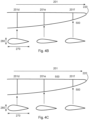
- Fig. 4A shows a schematic representation of a rotor blade tip according to the prior art.
- the cross section of the rotor blade changes along a length 201 of the rotor blade.
- three different cross sections are shown with lengths 201d, 201e and 201f. This changes both the rotor blade depth 270 and the rotor blade thickness.
- the rotor blade depth and the rotor blade thickness are reduced as the length 201 of the rotor blade 200 increases.
- Fig. 4B shows a schematic representation of a rotor blade tip according to one aspect of the present invention.
- the rotor blade thickness 280 is smaller at the length 201e than at a length 201f, which is arranged closer to the rotor blade tip 220.
- the rotor blade thickness 280 is therefore greater in an area that is closer to the rotor blade tip 220 than in an area that is further away from the rotor blade tip.
- a section 500 deflection section
- is provided in the area of length 201f which has a larger cross section than in a length that is arranged further away from the rotor blade tip 220.
- the relative profile thickness may have a minimum while the absolute profile thickness remains constant or even decreases strictly monotonically. However, it can also be the case that both the absolute and relative profile thicknesses both have a minimum. In any case, the relative profile thickness has a minimum.
- Fig. 4C shows a schematic representation of a rotor blade tip according to a further aspect of the present invention.
- a section 500 (deflection section) is provided between positions 201e and 201f, which has a substantially constant relative profile thickness 280.
- the rotor blade thickness 280 of the cross section at length 201f essentially corresponds to the rotor blade thickness 280 at length 201e.
- the rotor blade thickness can be kept larger by not reducing the relative profile thickness further towards the outside. However, this does not necessarily mean that the rotor blade thickness remains constant. It can also decrease externally. It just decreases less than in a design with a constantly decreasing relative profile thickness towards the outside.
- the rotor blade depth of the rotor blade is not changed, i.e. H. the rotor blade depth does not deviate from the basic shape.
- Fig. 5A shows a schematic representation of a rotor blade tip according to one aspect of the present invention.
- the rotor blade depth 270 can be less in the area of the length 201a than in the length 201f (which is closer to the rotor blade tip 220).
- a hybrid solution can be shown.
- the rotor blade 200 can have a constant, relatively high blade thickness 280 and a blade depth 270 that increases towards the tip 220.
- the absolute blade thickness can increase towards the outside.
- the sheet thickness 280 at position 201e can correspond to the sheet thickness 280 at position 201f.
- the rotor blade depth 270 may be greater at length 201f than at length 201e, which may be further away from the rotor blade tip.
- a deflection section 500 with an enlarged effective cross section (i.e. internal cross section) can thus be provided in the area of length 201f.
- Fig. 5B shows a schematic representation of a rotor blade according to one aspect of the present invention.
- Fig. 5B Another hybrid solution for designing the deflection section 500 is shown.
- the profile thickness increases in the direction of the rotor blade tip, for example from a length 201e to a length 201f, while the rotor blade depth 270 also increases. In other words, both the rotor blade thickness and the rotor blade depth increase towards the rotor blade tip.
- a deflection section 500 is thus provided in the area of the length 201f of the rotor blade 200.
- Fig. 6A shows a schematic representation of a blade depth profile of a rotor blade according to the prior art.
- Fig. 6B shows a corresponding representation according to an aspect of the present invention.
- a section 500 is provided with a length of 201g, which has a greater blade depth 270 in sections. Due to the greater blade depth 270, a cross section of the rotor blade 200 can be enlarged.
- the sheet thickness 280 can be increased in sections.
- both the blade thickness 280 and the blade depth 270 may be increased in the section 500.
- Fig. 7A shows a schematic representation of a profile thickness of a rotor blade according to the prior art
- Fig. 7B shows a schematic representation of a profile thickness curve according to one aspect of the present invention.
- the profile thickness 280 is increased at the length 201e, so that a local thickening can be provided in order to be able to implement the section 500, the section 500 having a larger flow-relevant cross section.
- further sections with an enlarged flow cross section can also be implemented in the area of the rotor blade between the rotor blade root and the rotor blade tip in order to be able to use air guiding elements in this area.
- the rotor blade depth and/or the rotor blade profile thickness can be increased in sections.
- the flow guide elements or flow control elements can represent bypasses, deflection bends or baffles.
- the rotor blade according to the invention an optimization of air guidance or air flow can be made possible in a hot air-based rotor blade heating inside the rotor blade.
- By increasing the flow cross section pressure losses inside the rotor blade can be avoided.
- With the rotor blade according to the invention the efficiency of a hot air blade heater can be increased.
- By providing the sections with an enlarged flow cross section, particularly in the area of the rotor blade tip the flow velocities in the area of a deflection and a reduction in wall friction can be achieved.
- Both the rotor blade thickness 280 and the profile thickness 290 typically change along the length 201 of the rotor blade. Typically, the rotor blade thickness 280 and the profile thickness 290 decrease towards the area of the rotor blade tip 220. These changes are due to both aerodynamics and manufacturing technology.
- the present invention proposes to deviate from these aerodynamically and/or production-related rotor blade curves and to provide at least one section in the area of the rotor blade tip in which the rotor blade thickness and/or the profile thickness does not decrease but rather remains constant at least in sections. Such a deviation of the rotor blade geometry from a usual rotor blade geometry occurs in order to provide a section which allows a larger available flow cross section. An air deflection element can be placed in this section to redirect heated air in the area of the rotor blade tip.
- the flow cross section that is effectively available - for an air flow within the rotor blade - can be increased in a section of the rotor blade, particularly in the area of the rotor blade tip, in order to improve deflection of the air flow. This can be done in particular by increasing the space required for the deflection by increasing the flow cross section. This also increases the volume available for corresponding air guiding elements. This allows a greater variation in the possible air guiding elements.
- rotor blade depth profile depth
- rotor blade thickness profile thickness
- the rotor blade depth can be increased in the area of the rotor blade tip. This leads to an increase in the rotor blade depth, for example with the same profiling of the rotor blade.
- the absolute thickness of the rotor blade can be increased compared to the rotor blade according to the prior art.
- the profile thickness in the area of the rotor blade tip can be increased.
- the rotor blade depth can remain small (as in rotor blades according to the prior art), while the absolute thickness of the rotor blade is increased.
- both the rotor blade depth and the relative thickness of the rotor blade profile can be increased in order to increase the flow cross section. This can in particular lead to a significant increase in the available flow cross section.
- the flow cross section can be increased by using thicker profiles and a simultaneously increased blade depth in the area of the rotor blade tip.
- the deflection sections can optionally have a maximum length of up to 30% of the rotor blade length or 15% of the rotor diameter. These rotor blades can optionally have a separation point.
- the deflection area can optionally have a maximum length of 10% of the blade length.
Landscapes
- Engineering & Computer Science (AREA)
- Life Sciences & Earth Sciences (AREA)
- Sustainable Development (AREA)
- Sustainable Energy (AREA)
- Chemical & Material Sciences (AREA)
- Combustion & Propulsion (AREA)
- Mechanical Engineering (AREA)
- General Engineering & Computer Science (AREA)
- Physics & Mathematics (AREA)
- Fluid Mechanics (AREA)
- Thermal Sciences (AREA)
- Wind Motors (AREA)
Priority Applications (3)
| Application Number | Priority Date | Filing Date | Title |
|---|---|---|---|
| EP22173045.0A EP4276300A1 (fr) | 2022-05-12 | 2022-05-12 | Pale de rotor pour éoliennes et éolienne |
| US18/302,450 US20230366370A1 (en) | 2022-05-12 | 2023-04-18 | Wind turbine rotor blade and wind turbine |
| CN202310532186.4A CN117052589A (zh) | 2022-05-12 | 2023-05-11 | 风能设施转子叶片和风能设施 |
Applications Claiming Priority (1)
| Application Number | Priority Date | Filing Date | Title |
|---|---|---|---|
| EP22173045.0A EP4276300A1 (fr) | 2022-05-12 | 2022-05-12 | Pale de rotor pour éoliennes et éolienne |
Publications (1)
| Publication Number | Publication Date |
|---|---|
| EP4276300A1 true EP4276300A1 (fr) | 2023-11-15 |
Family
ID=81648220
Family Applications (1)
| Application Number | Title | Priority Date | Filing Date |
|---|---|---|---|
| EP22173045.0A Pending EP4276300A1 (fr) | 2022-05-12 | 2022-05-12 | Pale de rotor pour éoliennes et éolienne |
Country Status (3)
| Country | Link |
|---|---|
| US (1) | US20230366370A1 (fr) |
| EP (1) | EP4276300A1 (fr) |
| CN (1) | CN117052589A (fr) |
Citations (6)
| Publication number | Priority date | Publication date | Assignee | Title |
|---|---|---|---|---|
| EP1788239A2 (fr) * | 2005-11-18 | 2007-05-23 | General Electric Company | Rotor d'une éolienne et procédé pour contrôler la température à l'intérieur du moyeu de rotor |
| DE102010051296A1 (de) * | 2010-11-12 | 2012-05-16 | Nordex Energy Gmbh | Rotorblatt sowie Verfahren zum Enteisen des Rotorblatts einer Windenergieanlage |
| DK201470503A1 (en) * | 2014-08-21 | 2016-02-29 | Gen Electric | System and method for deicing wind turbine rotor blades |
| WO2017021350A1 (fr) | 2015-07-31 | 2017-02-09 | Wobben Properties Gmbh | Pale d'éolienne |
| WO2018211055A1 (fr) | 2017-05-18 | 2018-11-22 | Wobben Properties Gmbh | Pale de rotor d'éolienne |
| CN111379676A (zh) * | 2020-03-09 | 2020-07-07 | 中国科学院工程热物理研究所 | 一种气热除冰装置及风能动力系统 |
-
2022
- 2022-05-12 EP EP22173045.0A patent/EP4276300A1/fr active Pending
-
2023
- 2023-04-18 US US18/302,450 patent/US20230366370A1/en active Pending
- 2023-05-11 CN CN202310532186.4A patent/CN117052589A/zh active Pending
Patent Citations (6)
| Publication number | Priority date | Publication date | Assignee | Title |
|---|---|---|---|---|
| EP1788239A2 (fr) * | 2005-11-18 | 2007-05-23 | General Electric Company | Rotor d'une éolienne et procédé pour contrôler la température à l'intérieur du moyeu de rotor |
| DE102010051296A1 (de) * | 2010-11-12 | 2012-05-16 | Nordex Energy Gmbh | Rotorblatt sowie Verfahren zum Enteisen des Rotorblatts einer Windenergieanlage |
| DK201470503A1 (en) * | 2014-08-21 | 2016-02-29 | Gen Electric | System and method for deicing wind turbine rotor blades |
| WO2017021350A1 (fr) | 2015-07-31 | 2017-02-09 | Wobben Properties Gmbh | Pale d'éolienne |
| WO2018211055A1 (fr) | 2017-05-18 | 2018-11-22 | Wobben Properties Gmbh | Pale de rotor d'éolienne |
| CN111379676A (zh) * | 2020-03-09 | 2020-07-07 | 中国科学院工程热物理研究所 | 一种气热除冰装置及风能动力系统 |
Also Published As
| Publication number | Publication date |
|---|---|
| CN117052589A (zh) | 2023-11-14 |
| US20230366370A1 (en) | 2023-11-16 |
Similar Documents
| Publication | Publication Date | Title |
|---|---|---|
| EP3625454B1 (fr) | Pale de rotor d'éolienne | |
| EP1113145B1 (fr) | Aube pour turbine a gaz avec section de mesure sur le bord de fuite | |
| EP2025945B1 (fr) | Machine de traitement des écoulements dotée d'un creux de paroi de canal de ceinture | |
| EP2984338B1 (fr) | Pale de rotor d'éolienne | |
| EP3329120B1 (fr) | Pale d'éolienne | |
| EP3548732B1 (fr) | Pale d'éolienne et éolienne | |
| EP2366625A2 (fr) | Moteur d'aéronef doté d'un échangeur thermique à huile optimisé | |
| EP2984334B1 (fr) | Pale de rotor d'éolienne et éolienne | |
| DE102014111707A1 (de) | System und Verfahren zum Enteisen von Windkraftanlagenrotorblättern | |
| EP3755899B1 (fr) | Pale de rotor d'une installation éolienne comprenant une plaque de déviation de la couche limite | |
| EP3147499B1 (fr) | Pale de rotor a profil optimise contre le bruit et procede de fabrication d'une pale de rotor | |
| EP3399183B1 (fr) | Pale de rotor d'une éolienne | |
| EP4276300A1 (fr) | Pale de rotor pour éoliennes et éolienne | |
| EP3109465B1 (fr) | Pale de rotor d'éolienne dotée d'un dispositif de chauffage electrique | |
| EP3735533B1 (fr) | Procédé pour commander une éolienne et éolienne | |
| EP4151856A1 (fr) | Pale de rotor d'éolienne | |
| EP4180654A1 (fr) | Pale de rotor pour éoliennes | |
| EP4191053A1 (fr) | Pale de rotor pour éoliennes | |
| DE19909899A1 (de) | Schaufeln mit veränderbarer Profilgeometrie | |
| CH700422B1 (de) | Axial durchströmte Windturbine. | |
| EP4303436A1 (fr) | Pale de rotor pour éoliennes et éolienne | |
| EP3969740B1 (fr) | Éolienne et pale de rotor d'éolienne | |
| EP3735530B1 (fr) | Pale de rotor pour éolienne et procédé | |
| EP4306797A1 (fr) | Pale de rotor pour éoliennes et éolienne | |
| EP4344031A1 (fr) | Générateur pour une éolienne pour générer de l'énergie électrique à partir d'énergie cinétique, éolienne et utilisation de plusieurs générateurs vortex destinés à être agencés sur une section de surface périphérique extérieure d'une éolienne |
Legal Events
| Date | Code | Title | Description |
|---|---|---|---|
| PUAI | Public reference made under article 153(3) epc to a published international application that has entered the european phase |
Free format text: ORIGINAL CODE: 0009012 |
|
| STAA | Information on the status of an ep patent application or granted ep patent |
Free format text: STATUS: THE APPLICATION HAS BEEN PUBLISHED |
|
| AK | Designated contracting states |
Kind code of ref document: A1 Designated state(s): AL AT BE BG CH CY CZ DE DK EE ES FI FR GB GR HR HU IE IS IT LI LT LU LV MC MK MT NL NO PL PT RO RS SE SI SK SM TR |
|
| STAA | Information on the status of an ep patent application or granted ep patent |
Free format text: STATUS: REQUEST FOR EXAMINATION WAS MADE |