EP4275929A1 - Verbundlenkerachse - Google Patents
Verbundlenkerachse Download PDFInfo
- Publication number
- EP4275929A1 EP4275929A1 EP23168702.1A EP23168702A EP4275929A1 EP 4275929 A1 EP4275929 A1 EP 4275929A1 EP 23168702 A EP23168702 A EP 23168702A EP 4275929 A1 EP4275929 A1 EP 4275929A1
- Authority
- EP
- European Patent Office
- Prior art keywords
- side arm
- beam axle
- opening
- wheel carrier
- wheel
- Prior art date
- Legal status (The legal status is an assumption and is not a legal conclusion. Google has not performed a legal analysis and makes no representation as to the accuracy of the status listed.)
- Granted
Links
Images


Classifications
-
- B—PERFORMING OPERATIONS; TRANSPORTING
- B60—VEHICLES IN GENERAL
- B60G—VEHICLE SUSPENSION ARRANGEMENTS
- B60G7/00—Pivoted suspension arms; Accessories thereof
- B60G7/001—Suspension arms, e.g. constructional features
-
- B—PERFORMING OPERATIONS; TRANSPORTING
- B60—VEHICLES IN GENERAL
- B60G—VEHICLE SUSPENSION ARRANGEMENTS
- B60G21/00—Interconnection systems for two or more resiliently-suspended wheels, e.g. for stabilising a vehicle body with respect to acceleration, deceleration or centrifugal forces
- B60G21/02—Interconnection systems for two or more resiliently-suspended wheels, e.g. for stabilising a vehicle body with respect to acceleration, deceleration or centrifugal forces permanently interconnected
- B60G21/04—Interconnection systems for two or more resiliently-suspended wheels, e.g. for stabilising a vehicle body with respect to acceleration, deceleration or centrifugal forces permanently interconnected mechanically
- B60G21/05—Interconnection systems for two or more resiliently-suspended wheels, e.g. for stabilising a vehicle body with respect to acceleration, deceleration or centrifugal forces permanently interconnected mechanically between wheels on the same axle but on different sides of the vehicle, i.e. the left and right wheel suspensions being interconnected
- B60G21/051—Trailing arm twist beam axles
- B60G21/052—Mounting means therefor
-
- B—PERFORMING OPERATIONS; TRANSPORTING
- B60—VEHICLES IN GENERAL
- B60G—VEHICLE SUSPENSION ARRANGEMENTS
- B60G21/00—Interconnection systems for two or more resiliently-suspended wheels, e.g. for stabilising a vehicle body with respect to acceleration, deceleration or centrifugal forces
- B60G21/02—Interconnection systems for two or more resiliently-suspended wheels, e.g. for stabilising a vehicle body with respect to acceleration, deceleration or centrifugal forces permanently interconnected
- B60G21/04—Interconnection systems for two or more resiliently-suspended wheels, e.g. for stabilising a vehicle body with respect to acceleration, deceleration or centrifugal forces permanently interconnected mechanically
- B60G21/05—Interconnection systems for two or more resiliently-suspended wheels, e.g. for stabilising a vehicle body with respect to acceleration, deceleration or centrifugal forces permanently interconnected mechanically between wheels on the same axle but on different sides of the vehicle, i.e. the left and right wheel suspensions being interconnected
- B60G21/051—Trailing arm twist beam axles
-
- B—PERFORMING OPERATIONS; TRANSPORTING
- B60—VEHICLES IN GENERAL
- B60G—VEHICLE SUSPENSION ARRANGEMENTS
- B60G7/00—Pivoted suspension arms; Accessories thereof
- B60G7/008—Attaching arms to unsprung part of vehicle
-
- B—PERFORMING OPERATIONS; TRANSPORTING
- B60—VEHICLES IN GENERAL
- B60G—VEHICLE SUSPENSION ARRANGEMENTS
- B60G2200/00—Indexing codes relating to suspension types
- B60G2200/20—Semi-rigid axle suspensions
-
- B—PERFORMING OPERATIONS; TRANSPORTING
- B60—VEHICLES IN GENERAL
- B60G—VEHICLE SUSPENSION ARRANGEMENTS
- B60G2200/00—Indexing codes relating to suspension types
- B60G2200/20—Semi-rigid axle suspensions
- B60G2200/21—Trailing arms connected by a torsional beam, i.e. twist-beam axles
-
- B—PERFORMING OPERATIONS; TRANSPORTING
- B60—VEHICLES IN GENERAL
- B60G—VEHICLE SUSPENSION ARRANGEMENTS
- B60G2204/00—Indexing codes related to suspensions per se or to auxiliary parts
- B60G2204/10—Mounting of suspension elements
-
- B—PERFORMING OPERATIONS; TRANSPORTING
- B60—VEHICLES IN GENERAL
- B60G—VEHICLE SUSPENSION ARRANGEMENTS
- B60G2206/00—Indexing codes related to the manufacturing of suspensions: constructional features, the materials used, procedures or tools
- B60G2206/01—Constructional features of suspension elements, e.g. arms, dampers, springs
- B60G2206/20—Constructional features of semi-rigid axles, e.g. twist beam type axles
-
- B—PERFORMING OPERATIONS; TRANSPORTING
- B60—VEHICLES IN GENERAL
- B60G—VEHICLE SUSPENSION ARRANGEMENTS
- B60G2206/00—Indexing codes related to the manufacturing of suspensions: constructional features, the materials used, procedures or tools
- B60G2206/01—Constructional features of suspension elements, e.g. arms, dampers, springs
- B60G2206/50—Constructional features of wheel supports or knuckles, e.g. steering knuckles, spindle attachments
-
- B—PERFORMING OPERATIONS; TRANSPORTING
- B60—VEHICLES IN GENERAL
- B60G—VEHICLE SUSPENSION ARRANGEMENTS
- B60G2206/00—Indexing codes related to the manufacturing of suspensions: constructional features, the materials used, procedures or tools
- B60G2206/01—Constructional features of suspension elements, e.g. arms, dampers, springs
- B60G2206/80—Manufacturing procedures
- B60G2206/82—Joining
- B60G2206/8201—Joining by welding
-
- B—PERFORMING OPERATIONS; TRANSPORTING
- B60—VEHICLES IN GENERAL
- B60G—VEHICLE SUSPENSION ARRANGEMENTS
- B60G2206/00—Indexing codes related to the manufacturing of suspensions: constructional features, the materials used, procedures or tools
- B60G2206/01—Constructional features of suspension elements, e.g. arms, dampers, springs
- B60G2206/80—Manufacturing procedures
- B60G2206/82—Joining
- B60G2206/8207—Joining by screwing
Definitions
- the invention relates to a torsion beam axle with two tubular side arms, a wheel carrier flange being welded to the front side of an end section of a tubular side arm.
- a torsion beam axle consists of two bending and torsion-resistant side arms and a cross member, which connects the two side arms in a torsion-flexible manner.
- a torsion beam axle is usually used as the rear axle for front-wheel drive vehicles and provides the load-bearing connection between the wheels and the body in the chassis system.
- the wheels are connected to the side arms. All forces and moments are transferred between the wheel and vehicle body via the torsion beam axle.
- the Wheel suspension is crucial for stable driving behavior and driving safety.
- An advantageous design of the side arms to achieve high rigidity with low weight is to design the side arms in tubular form with a direct connection to a wheel carrier flange.
- the well-known torsion beam axle has a wheel carrier flange welded to the front of an end section, i.e. in front of the end of a tubular side arm.
- Generation 3 wheel bearings have a flange on the outer and inner ring for attachment to the chassis and for holding the brake disc and rim.
- the wheel-side inner ring flange serves as a wheel hub.
- the outer ring flange is screwed to the wheel carrier. Access to the assembly openings in the flanges is made more difficult.
- the use of third-generation wheel bearings in torsion beam axles therefore usually requires an attached wheel carrier flange with one or more reinforcing components.
- the invention is based on the object of creating a torsion beam axle with a functionally improved connection to a wheel bearing unit, in particular for the assembly of a third generation wheel bearing.
- top and bottom front and rear, horizontal and vertical or longitudinal and transverse directions as well as top and bottom refer to the installation position of the torsion beam axle, its components and add-on components in a motor vehicle.
- a torsion beam axle essentially comprises two wheel-guiding side arms, also called trailing arms, and a cross member connecting the two side arms.
- a wheel carrier flange is welded to one end or to one end section of a side arm.
- the side arm has an opening in a wall section, which is designed and intended so that a screw connection means, in particular a threaded bolt, can be guided via the opening through the side arm to the wheel carrier flange and through a through opening in the wheel carrier flange or for mounting and fixing a Wheel bearing unit can be guided.
- a screw connection means in particular a threaded bolt
- the opening in the side arm allows access to a mounting opening in the fixed flange of a wheel bearing unit on the wheel carrier flange side.
- the screw connection means can be passed through the opening in the wall section of the side arm and through the open end face of the end section of the side arm. The screw connection means is then guided through a through opening in the wheel carrier flange and screwed into a mounting opening in the outer ring flange of the bearing unit.
- the embodiment according to the invention creates a torsion beam axle with a functionally advantageous connection of a wheel bearing unit, in particular a wheel bearing unit with a third generation wheel bearing.
- the torsion beam axle according to the invention makes it possible to screw the wheel bearing or the bearing unit to the wheel carrier flange through the side arm. This is particularly possible if a wheel bearing with a three-point screw connection is used, as is the case with third generation wheel bearings.
- the fixed one The outer ring flange of a third generation wheel bearing has three mounting openings that are offset from one another. The lower assembly opening is positioned so that it is accessible for a screw fastener from the inside through the opening in the side arm and the open end of the side arm.
- a side arm can be curved along its length.
- the end section of the tubular side arm is curved.
- the end section is directed outwards in relation to the installation position of the torsion beam axle in a motor vehicle.
- the opening is provided in an inner wall section of the end section.
- the inner wall section lies on the side of the side arm facing the cross member.
- the inner wall section of the arcuate end section has a larger radius of curvature than the outer wall section.
- An advantageous embodiment with regard to the utilization of the installation space as well as the stiffness and strength behavior provides that the opening in the wall section of the side arm has a circumferential, self-contained edge.
- a further advantageous embodiment of the torsion beam axle provides that a reinforcing component is arranged on the top side of the side arm between the end section and the wheel carrier flange.
- the reinforcing component is preferably designed as a sheet metal part.
- the reinforcing component is a shell-shaped sheet metal part.
- the sheet metal part is supported on the one hand on the top of the tubular side arm and on the other hand on the wheel carrier flange.
- the sheet metal part is cohesively joined to the side arm and the wheel carrier flange.
- the sheet metal part has at least one recess, the recess being designed and intended so that a screw connection means can be guided via the recess through the sheet metal part and through a through opening in the wheel carrier flange.
- two recesses are provided in the sheet metal part. This enable accessibility to the two upper mounting openings in the outer ring flange of the wheel bearing unit.
- the recesses on the outer edge of the sheet metal part are preferably open.
- At least one impression or bead can be provided in one or both tubular side arms of the torsion beam axle.
- an impression is arranged in a side arm in an area in front of the opening in the side arm, namely in a longitudinal section of the side arm between the connection of the cross member and the opening through which the screw connection means can be guided through the side arm.
- the impression or bead improves the stiffness behavior of the side arm, especially with regard to the weakening of the material caused by the opening.
- impressions it is also possible for impressions to serve as clearance for other structural or add-on components of the wheel suspension.
- An embodiment that improves the basic functionality of the torsion beam axle further provides that a spring plate is arranged in the gusset between the side arm and the cross member.
- the spring plate is at least partially welded to both the side arm and the cross member.
- the Figure 1 shows a torsion beam axle 1 for a motor vehicle.
- the torsion beam axle 1 essentially comprises two wheel-guiding side arms 2, 3 and a cross member 4 connecting the two side arms 2, 3.
- the side arms 2, 3 are tubular and have a base body 5 formed from a tube. In their longitudinal extent, the side arms 2, 3 are curved in an arc. At a front end 6, the side arms 2, 3 each have a bearing bush 7.
- the bearing bushes 7 are used to hold a rubber-metal bearing, via which a pivotable bearing on the vehicle body takes place.
- each side arm 2, 3 has a wheel carrier flange 9.
- the wheel carrier flange 9 is welded at the end to the end section 8 of the tubular side arm 2, 3.
- a wheel bearing unit 10 is fixed to a wheel carrier flange 9.
- the wheel bearing unit 10 includes a wheel bearing 11 of generation 3.
- the wheel bearing unit 10 is in the Figure 5 presented in a technically schematized manner. The same applies to wheel bearing 11.
- each wheel bearing unit 10 has an outer ring flange 12 on the wheel carrier flange side and an inner ring flange 13 on the wheel side.
- the inner ring flange 13 serves as a wheel hub.
- the outer ring flange 12 is screwed to the wheel carrier flange 9.
- the side arm 2, 3 has an opening 15 in a wall section 14.
- the rear end section 8 is curved.
- the opening 15 is located on the inner side 16 of the side arm 2, 3 facing the center of the vehicle.
- the opening 15 is designed and intended for a screw connection means to pass through the opening 15 and through the side arm 2, 3 to the wheel carrier flange 9 and there through a Through opening 17 in the wheel carrier flange 9 can be guided in order to be screwed into a threaded hole 18 of the outer ring flange 12 of the wheel bearing unit 10.
- the lower threaded hole 18 in the outer ring flange 12 is accessible from the back through the side arm 2, 3 and the end face 19 of the end section 8.
- the opening 15 is circular and has a circumferential, self-contained edge 20.
- a reinforcing component 22 is arranged on the top side of the side arm 2, 3.
- the reinforcing component 22 extends between the side arm 2, 3 and the wheel carrier flange 9.
- the reinforcing component 22 is a sheet metal part 23, which is cohesively joined to the top 21 of the side arm 2, 3 on the one hand and to the wheel carrier flange 9 on the other hand.
- Two recesses 24 are provided in the sheet metal part 23.
- the recesses 24 are set up and intended so that a screw connection means can be guided through the recesses 24 in the sheet metal part 23 and through an upper through opening 25 in the wheel carrier flange 9.
- a through opening 25 in the wheel carrier flange 9 corresponds to a recess 24.
- a through opening 25 in turn communicates with an upper threaded hole 26 in the outer ring flange 12 of the wheel bearing unit 10.
- the outer ring flange 12 is configured triangularly and has a total of three threaded holes 18 and 26, via which the wheel bearing unit 10 is fixed to the wheel carrier flange 9.
- the lower threaded bore 18 is accessible through the opening 15 from the side of the side arm 2, 3 facing away from the wheel carrier flange 9.
- the opening 15 is positioned so that a screw connection means, in particular a screw bolt, can be guided in a straight line from behind through the side arm 2, 3 through the through opening 17 into the threaded hole 18 and can be screwed in.
- the two upper threaded holes 26 in the wheel carrier flange 9 are connected via the recesses 24 in the reinforcing component 22 accessible.
- a screw connection means, in particular a screw bolt can be guided from the back through the through opening 25 in the wheel carrier flange 9 and screwed into the threaded hole 26.
- a recess 24 is open on the outer edge 27 of the sheet metal part 23.
- each tubular side arm 2, 3 has an impression 28.
- the impression 28 is arranged on the inside of the side arm 2, 3 from the cross member 4 in front of the opening 15.
- a spring plate 30 is provided in a gusset 29 between a side arm 2, 3 and the cross member 4.
- the spring plate 30 is joined to the cross member 4 and to a side arm 2, 3.
- a connecting web 31 of the spring plate 30 includes the end section 8 of a side arm 2, 3 in some areas on the inner wall section 14.
- the connecting web 31 is located between the opening 15 and the impression 28.
Landscapes
- Engineering & Computer Science (AREA)
- Mechanical Engineering (AREA)
- Vehicle Body Suspensions (AREA)
Abstract
Description
- Die Erfindung betrifft eine Verbundlenkerachse mit zwei rohrförmigen Seitenarmen, wobei stirnseitig an einem Endabschnitt eines rohrförmigen Seitenarms ein Radträgerflansch geschweißt ist.
- Eine Verbundlenkerachse besteht vom grundsätzlichen Aufbau her aus zwei biege- und verdrehsteifen Seitenarmen und einem Querträger, welcher die beiden Seitenarme torsionsweich verbindet. Eine Verbundlenkerachse wird üblicherweise als Hinterachse für Fahrzeuge mit Frontantrieb eingesetzt und übernimmt die tragende Verbindung zwischen Rädern und Karosserie im Fahrwerksystem. An den Seitenarmen sind die Räder angebunden. Über die Verbundlenkerachse werden alle Kräfte und Momente zwischen Rad- und Fahrzeugaufbau übertragen. Die Radaufhängung ist dabei entscheidend für ein stabiles Fahrverhalten und die Fahrsicherheit.
- Durch die
DE 295 19 965 U1 zählt ein Kraftfahrzeug-Radträger für Mehrlenkerachsen zum Stand der Technik. - Eine vorteilhafte Ausgestaltung der Seitenarme zur Erzielung einer hohen Steifigkeit bei geringem Gewicht ist die Ausführung der Seitenarme in Rohrform mit direkter Anbindung eines Radträgerflansches.
- Bei der aus der
DE 10 2009 010 098 B4 bekannten Verbundlenkerachse ist stirnseitig an einen Endabschnitt, also vor das Ende eines rohrförmigen Seitenarms, ein Radträgerflansch geschweißt. - Im System der Radaufhängung ist die Anbindung der Radlagereinheiten technisch anspruchsvoll. Insbesondere bei Radlagereinheiten mit Radlagern der sogenannten dritten Generation (Generation 3) ist die Schnittstelle zwischen dem Radträgerflansch und der Radlagereinheit wegen der komplexen Geometrien und Bauraumvorgaben nicht immer einfach zu realisieren. Radlager der Generation 3 besitzen am Außen- und am Innenring je einen Flansch für die Befestigung am Fahrwerk und für die Aufnahme von Bremsscheibe und Felge. Der radseitige Innenringflansch dient als Radnabe. Der Außenringflansch wird mit dem Radträger verschraubt. Hierbei ist die Zugänglichkeit der Montageöffnungen in den Flanschen erschwert. Die Anwendung von Radlagern der dritten Generation bei Verbundlenkerachsen erfordert daher üblicherweise einen aufgesetzten Radträgerflansch mit einem oder mehreren Verstärkungsbauteilen.
- Der Erfindung liegt ausgehend vom Stand der Technik die Aufgabe zugrunde, eine Verbundlenkerachse zu schaffen mit einer funktional verbesserten Anbindung einer Radlagereinheit, insbesondere für die Montage eines Radlagers der dritten Generation.
- Die Lösung dieser Aufgabe besteht in einer Verbundlenkerachse gemäß Anspruch 1.
- Vorteilhafte Ausgestaltungen und Weiterbildungen des erfindungsgemäßen Verbundlenkerachse sind Gegenstand der abhängigen Ansprüche.
- Ausgestaltungen und Modifikationen von Merkmalen der Verbundlenkerachse, die einzeln oder in Kombination die Erfindung technisch vorteilhaft ausgestalten, ergeben sich aus der Beschreibung und den beigefügten Zeichnungen.
- Begriffe wie oben und unten, vorne und hinten, horizontal und vertikal oder Längsrichtung und Querrichtung sowie Oberseite und Unterseite beziehen sich auf die Einbaulage der Verbundlenkerachse, deren Bauteile und Anbaukomponenten in einem Kraftfahrzeug.
- Eine Verbundlenkerachse umfasst im Wesentlichen zwei radführende Seitenarme, auch Längslenker genannt, und einen die beiden Seitenarme verbindenden Querträger. Jeweils stirnseitig an einem Ende bzw. stirnseitig an einem Endabschnitt eines Seitenarms ist ein Radträgerflansch angeschweißt.
- Erfindungsgemäß weist der Seitenarm in einem Wandabschnitt eine Öffnung auf, welche dazu eingerichtet und bestimmt ist, dass ein Schraubverbindungsmittel, insbesondere einen Gewindebolzen, über die Öffnung durch den Seitenarm bis zum Radträgerflansch und durch eine Durchgangsöffnung im Radträgerflansch führbar ist bzw. zur Montage und Festlegung einer Radlagereinheit geführt werden kann.
- Die Öffnung im Seitenarm ermöglicht die Zugänglichkeit zu einer Montageöffnung im radträgerflanschseitigen feststehenden Flansch einer Radlagereinheit. Das Schraubverbindungsmittel kann durch die Öffnung im Wandabschnitt des Seitenarms und durch die offene Stirnseite des Endabschnitts des Seitenarms geführt werden. Das Schraubverbindungsmittel wird dann durch eine Durchgangsöffnung im Radträgerflansch geführt und in eine Montageöffnung im Außenringflansch der Lagereinheit geschraubt.
- Die erfindungsgemäße Ausgestaltung schafft eine Verbundlenkerachse mit einer funktional vorteilhaften Anbindung einer Radlagereinheit, insbesondere einer Radlagereinheit mit einem Radlager der dritten Generation. Die erfindungsgemäße Verbundlenkerachse ermöglicht es, das Radlager bzw. die Lagereinheit mit dem Radträgerflansch durch den Seitenarm hindurch zu verschrauben. Dies ist insbesondere möglich, wenn ein Radlager mit Drei-Punkt-Verschraubung verwendet wird, wie dies bei den Radlagern der dritten Generation der Fall ist. Der feststehende Außenringflansch eines Radlagers der dritten Generation weist drei Montageöffnungen auf, die versetzt zueinander angeordnet sind. Die untere Montageöffnung wird so positioniert, dass deren Zugänglichkeit für ein Schraubverbindungsmittel von innen durch die Öffnung im Seitenarm und das stirnseitig offene Ende des Seitenarms gegeben ist.
- Ein Seitenarm kann in seiner Längserstreckung bogenförmig verlaufen. Insbesondere ist der Endabschnitt des rohrförmigen Seitenarms bogenförmig ausgebildet. Hierbei ist der Endabschnitt bezogen auf die Einbaulage der Verbundlenkerachse in einem Kraftfahrzeug nach außen gerichtet. Die Öffnung ist in einem innenliegenden Wandabschnitt des Endabschnitts vorgesehen. Der innenliegende Wandabschnitt liegt auf der zum Querträger gerichteten Seite des Seitenarms. Der innenliegende Wandabschnitt des bogenförmigen Endabschnitts weist einen größeren Krümmungsradius auf als der außenliegende Wandabschnitt.
- Eine hinsichtlich der Ausnutzung des Bauraums sowie des Steifigkeits- und Festigkeitsverhaltens vorteilhafte Ausgestaltung sieht vor, dass die Öffnung im Wandabschnitt des Seitenarms einen umlaufenden in sich geschlossenen Rand aufweist.
- Eine weitere vorteilhafte Ausgestaltung der Verbundlenkerachse sieht vor, dass oberseitig des Seitenarms zwischen dem Endabschnitt und dem Radträgerflansch ein Verstärkungsbauteil angeordnet ist.
- Das Verstärkungsbauteil ist vorzugsweise als Blechformteil ausgeführt. Insbesondere ist das Verstärkungsbauteil ein schalenförmiges Blechformteil. Das Blechformteil stützt sich einerseits an der Oberseite des rohrförmigen Seitenarms und andererseits am Radträgerflansch ab. Insbesondere ist das Blechformteil stoffschlüssig mit dem Seitenarm und dem Radträgerflansch gefügt. Das Blechformteil weist zumindest eine Ausnehmung auf, wobei die Ausnehmung dazu eingerichtet und bestimmt ist, dass ein Schraubverbindungsmittel über die Ausnehmung durch das Blechformteil und durch eine Durchgangsöffnung im Radträgerflansch geführt werden kann. Insbesondere sind bei einer Radlagereinheit mit einem Außenringflansch mit einer Drei-Punkt-Verschraubung zwei Ausnehmungen im Blechformteil vorgesehen. Diese ermöglichen die Zugänglichkeit der beiden oberen Montageöffnungen im Außenringflansch der Radlagereinheit.
- Vorzugsweise sind die Ausnehmungen am Außenrand des Blechformteils offen.
- Möglich ist es auch, dass die Ausnehmungen im Verstärkungsbauteil randseitig umlaufend geschlossen sind.
- In einem oder beiden rohrförmigen Seitenarmen der Verbundlenkerachse kann zumindest eine Einprägung oder Sicke vorgesehen sein. Insbesondere ist eine Einprägung in einem Seitenarm in einem Bereich vor der Öffnung im Seitenarm angeordnet, und zwar in einem Längenabschnitt des Seitenarms zwischen der Anbindung des Querträgers und der Öffnung, durch welche das Schraubverbindungsmittel durch den Seitenarm führbar ist. Die Einprägung bzw. Sicke verbessert das Steifigkeitsverhalten des Seitenarms, speziell im Hinblick auf die durch die Öffnung erzeugte Materialschwächung. Möglich ist es aber auch, dass Einprägungen als Freigang für weitere Bau- oder Anbaukomponenten der Radaufhängung dienen.
- Eine die grundsätzliche Funktionalität der Verbundlenkerachse verbessernde Ausgestaltung sieht des Weiteren vor, dass ein Federteller im Zwickel zwischen dem Seitenarm und dem Querträger angeordnet ist. Der Federteller ist sowohl mit dem Seitenarm als auch mit dem Querträger zumindest bereichsweise verschweißt.
- Die Erfindung ist nachfolgend anhand eines in den Zeichnungen dargestellten Ausführungsbeispiels näher beschrieben. Es zeigen:
- Figur 1
- eine Verbundlenkerachse in einer perspektivischen Darstellung;
- Figur 2
- einen Endabschnitt eines Seitenarms der Verbundlenkerachse mit am Radträgerflansch des Seitenarms montierter Radlagereinheit in einer Perspektive;
- Figur 3
- eine Ansicht entsprechend der Darstellung von
Figur 2 aus einer anderen Perspektive; - Figur 4
- eine rückseitige Ansicht auf den Endabschnitt eines Seitenarms und
- Figur 5
- den Endabschnitt des Seitenarms mit montierter Radlagereinheit teilweise in geschnittener Darstellung.
- Die
Figur 1 zeigt eine Verbundlenkerachse 1 für ein Kraftfahrzeug. Die Verbundlenkerachse 1 umfasst im Wesentlichen zwei radführende Seitenarme 2, 3 und einen die beiden Seitenarme 2, 3 verbindenden Querträger 4. - Die Seitenarme 2, 3 sind rohrförmig und besitzen einen aus einem Rohr gebildeten Grundkörper 5. In ihrer Längserstreckung verlaufen die Seitenarme 2, 3 bogenförmig gekrümmt. An einem vorderen Ende 6 weisen die Seitenarme 2, 3 jeweils eine Lagerbuchse 7 auf. Die Lagerbuchsen 7 dienen zur Aufnahme eines Gummimetalllagers, über welche eine schwenkbare Lagerung am Fahrzeugaufbau erfolgt.
- An einem hinteren Endabschnitt 8 weist jeder Seitenarm 2, 3 einen Radträgerflansch 9 auf. Der Radträgerflansch 9 ist stirnseitig an den Endabschnitt 8 des rohrförmigen Seitenarms 2, 3 geschweißt.
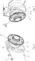
- An einem Radträgerflansch 9 wird jeweils eine Radlagereinheit 10 festgelegt. Die Radlagereinheit 10 umfasst ein Radlager 11 der Generation 3. Die Radlagereinheit 10 ist in der
Figur 5 technisch schematisiert dargestellt. Gleiches gilt für das Radlager 11. - Wie insbesondere in den
Figuren 2 und 3 zu erkennen, weist jede Radlagereinheit 10 einen radträgerflanschseitigen Außenringflansch 12 und einen radseitigen Innenringflansch 13 auf. Der Innenringflansch 13 dient als Radnabe. Der Außenringflansch 12 wird mit dem Radträgerflansch 9 verschraubt. - Anhand der
Figuren 4 und 5 erkennt man, dass der Seitenarm 2, 3 in einem Wandabschnitt 14 eine Öffnung 15 aufweist. Der hintere Endabschnitt 8 ist bogenförmig ausgebildet. Die Öffnung 15 liegt auf der zur Fahrzeugmitte gerichteten innenliegenden Seite 16 des Seitenarms 2, 3. Die Öffnung 15 ist dazu eingerichtet und bestimmt, dass ein Schraubverbindungsmittel durch die Öffnung 15 und durch den Seitenarm 2, 3 bis zum Radträgerflansch 9 und dort durch eine Durchgangsöffnung 17 im Radträgerflansch 9 geführt werden kann, um in eine Gewindebohrung 18 des Außenringflanschs 12 der Radlagereinheit 10 eingeschraubt zu werden. - Durch die Öffnung 15 im Seitenarm 2, 3 ist die untere Gewindebohrung 18 im Außenringflansch 12 von der Rückseite her durch den Seitenarm 2, 3 und die Stirnseite 19 des Endabschnitt 8 zugänglich.
- Die Öffnung 15 ist kreisrund und weist einen umlaufenden in sich geschlossenen Rand 20 auf.
- Oberseitig des Seitenarms 2, 3 ist ein Verstärkungsbauteil 22 angeordnet. Das Verstärkungsbauteil 22 erstreckt sich zwischen dem Seitenarm 2, 3 und dem Radträgerflansch 9. Das Verstärkungsbauteil 22 ist ein Blechformteil 23, welches einerseits mit der Oberseite 21 des Seitenarms 2, 3 und andererseits mit dem Radträgerflansch 9 stoffschlüssig gefügt ist. Im Blechformteil 23 sind zwei Ausnehmungen 24 vorgesehen. Die Ausnehmungen 24 sind dazu eingerichtet und bestimmt, dass ein Schraubverbindungsmittel durch die Ausnehmungen 24 im Blechformteil 23 und durch jeweils eine obere Durchgangsöffnung 25 im Radträgerflansch 9 geführt werden kann. Jeweils mit einer Ausnehmung 24 korrespondiert eine Durchgangsöffnung 25 im Radträgerflansch 9. Eine Durchgangsöffnung 25 wiederum kommuniziert jeweils mit einer oberen Gewindebohrung 26 im Außenringflansch 12 der Radlagereinheit 10.
- Wie insbesondere die
Figuren 2 und 3 zeigen, ist der Außenringflansch 12 dreieckförmig konfiguriert und besitzt insgesamt drei Gewindebohrungen 18 bzw. 26, über welche die Festlegung der Radlagereinheit 10 am Radträgerflansch 9 erfolgt. Die untere Gewindebohrung 18 ist über die Öffnung 15 von der dem Radträgerflansch 9 abgewandten Seite des Seitenarms 2, 3 durch diesen zugänglich. Die Öffnung 15 ist so positioniert, dass ein Schraubverbindungsmittel, insbesondere ein Schraubbolzen, geradlinig von hinten durch den Seitenarm 2, 3 durch die Durchgangsöffnung 17 in die Gewindebohrung 18 führbar ist und eingeschraubt werden kann. Die beiden oberen Gewindebohrungen 26 im Radträgerflansch 9 sind über die Ausnehmungen 24 im Verstärkungsbauteil 22 zugänglich. Ein Schraubverbindungsmittel, insbesondere ein Schraubbolzen, kann von der Rückseite her durch die Durchgangsöffnung 25 im Radträgerflansch 9 geführt und in die Gewindebohrung 26 geschraubt werden. - Eine Ausnehmung 24 ist am Außenrand 27 des Blechformteils 23 offen ist.
- Des Weiteren erkennt man insbesondere in den
Figuren 4 und 5 , dass jeder rohrförmige Seitenarm 2, 3 eine Einprägung 28 aufweist. Die Einprägung 28 ist innenseitig des Seitenarms 2, 3 vom Querträger 4 ausgehend vor der Öffnung 15 angeordnet. - In einem Zwickel 29 zwischen einem Seitenarm 2, 3 und dem Querträger 4 ist ein Federteller 30 vorgesehen. Der Federteller 30 ist mit dem Querträger 4 und mit einem Seitenarm 2, 3 gefügt. Hierbei umfasst ein Anbindungssteg 31 des Federtellers 30 den Endabschnitt 8 eines Seitenarms 2, 3 bereichsweise am innenliegenden Wandabschnitt 14. Der Anbindungssteg 31 befindet sich zwischen der Öffnung 15 und der Einprägung 28.
-
- 1 - Verbundlenkerachse
- 2 - Seitenarm
- 3 - Seitenarm
- 4 - Querträger
- 5 - Grundkörper
- 6 - vorderes Ende der Seitenarme
- 7 - Lagerbuchse
- 8 - Endabschnitt der Seitenarme
- 9 - Radträgerflansch
- 10 - Radlagereinheit
- 11 - Radlager
- 12 - Außenringflansch
- 13 - Innenringflansch
- 14 - Wandabschnitt
- 15 - Öffnung
- 16 - innenliegende Seite des Seitenarms
- 17 - Durchgangsöffnung
- 18 - Gewindebohrung
- 19 - Stirnseite
- 20 - Rand
- 21 - Oberseite
- 22 - Verstärkungsbauteil
- 23 - Blechformteil
- 24 - Ausnehmungen
- 25 - Durchgangsöffnung
- 26 - Gewindebohrung
- 27 - Außenrand
- 28 - Einprägung
- 29 - Zwickel
- 30 - Federteller
- 31 - Anbindungssteg
Claims (9)
- Verbundlenkerachse mit zwei rohrförmigen Seitenarmen (2, 3), wobei stirnseitig an einen Endabschnitt (8) eines rohrförmigen Seitenarms (2, 3) ein Radträgerflansch (9) geschweißt ist, dadurch gekennzeichnet, dass der Seitenarm (2, 3) in einem Wandabschnitt (14) eine Öffnung (15) aufweist, welche dazu eingerichtet und bestimmt ist, dass ein Schraubverbindungsmittel durch den Seitenarm (2, 3) und durch eine Durchgangsöffnung (17) im Radträgerflansch (9) führbar ist.
- Verbundlenkerachse nach Anspruch 1, dadurch gekennzeichnet, dass der Endabschnitt (8) bogenförmig ausgebildet ist und die Öffnung (15) in einem innenliegenden Wandabschnitt (14) des Endabschnitts (8) vorgesehen ist.
- Verbundlenkerachse nach Anspruch 1 oder 2, dadurch gekennzeichnet, dass die Öffnung (15) einen umlaufenden in sich geschlossenen Rand (20) aufweist.
- Verbundlenkerachse nach einem der Ansprüche 1 bis 3, dadurch gekennzeichnet, dass oberseitig des Seitenarms (2, 3) zwischen dem Endabschnitt (8) und dem Radträgerflansch (9) ein Verstärkungsbauteil (22) angeordnet ist.
- Verbundlenkerachse nach Anspruch 4, dadurch gekennzeichnet, dass das Verstärkungsbauteil (22) ein Blechformteil (23) ist, welches zumindest eine Ausnehmung (24) aufweist, wobei die Ausnehmung (24) dazu eingerichtet und bestimmt ist, dass ein Schraubverbindungsmittel durch das Blechformteil (23) und durch eine Durchgangsöffnung (25) im Radträgerflansch (9) führbar ist.
- Verbundlenkerachse nach Anspruch 5, dadurch gekennzeichnet, dass die Ausnehmung (24) am Außenrand (27) des Blechformteils (23) offen ist.
- Verbundlenkerachse nach Anspruch 5, dadurch gekennzeichnet, dass die Ausnehmung im Verstärkungsbauteil randseitig umlaufend geschlossen ist.
- Verbundlenkerachse nach einem der Ansprüche 1 bis 7, dadurch gekennzeichnet, dass der rohrförmige Seitenarm (2, 3) zumindest eine Einprägung (28) oder Sicke aufweist.
- Verbundlenkerachse nach einem der Ansprüche 1 bis 8, dadurch gekennzeichnet, dass ein Federteller (30) in einem Zwickel (29) zwischen einem Seitenarm (2, 3) und einem Querträger (4) angeordnet ist.
Applications Claiming Priority (1)
| Application Number | Priority Date | Filing Date | Title |
|---|---|---|---|
| DE102022111981.5A DE102022111981A1 (de) | 2022-05-12 | 2022-05-12 | Verbundlenkerachse |
Publications (2)
| Publication Number | Publication Date |
|---|---|
| EP4275929A1 true EP4275929A1 (de) | 2023-11-15 |
| EP4275929B1 EP4275929B1 (de) | 2024-05-22 |
Family
ID=88294957
Family Applications (1)
| Application Number | Title | Priority Date | Filing Date |
|---|---|---|---|
| EP23168702.1A Active EP4275929B1 (de) | 2022-05-12 | 2023-04-19 | Verbundlenkerachse |
Country Status (4)
| Country | Link |
|---|---|
| EP (1) | EP4275929B1 (de) |
| CN (1) | CN117048263A (de) |
| DE (1) | DE102022111981A1 (de) |
| ES (1) | ES2983102T3 (de) |
Citations (6)
| Publication number | Priority date | Publication date | Assignee | Title |
|---|---|---|---|---|
| DE29519965U1 (de) | 1995-12-16 | 1997-04-10 | Thyssen Industrie Ag, 45128 Essen | Kfz-Radträger für Mehrlenkerachsen |
| EP2327573A1 (de) * | 2009-11-18 | 2011-06-01 | Fiat Group Automobiles S.p.A. | Modular monolithischer Längslenker für eine Verbundlenkerachse, verwendbar für Vorder- und Hinterradantrieb |
| DE102009010098B4 (de) | 2009-02-24 | 2013-09-05 | Benteler Automobiltechnik Gmbh | Verbundlenkerachse und Verfahren zu ihrer Herstellung |
| DE102014107896A1 (de) * | 2014-06-04 | 2015-12-17 | Benteler Automobiltechnik Gmbh | Flanschplatte zum Anbinden einer Verbundlenkerachse an ein Radlager |
| CN106828009A (zh) * | 2017-03-03 | 2017-06-13 | 袁璐 | 后悬架扭力梁结构 |
| CN208978585U (zh) * | 2018-09-13 | 2019-06-14 | 威马智慧出行科技(上海)有限公司 | 一种汽车后扭力梁 |
Family Cites Families (3)
| Publication number | Priority date | Publication date | Assignee | Title |
|---|---|---|---|---|
| CN202115303U (zh) | 2010-12-09 | 2012-01-18 | 金华福多纳机械有限公司 | 变截面车辆纵臂构件 |
| DE102018205996B4 (de) * | 2018-04-19 | 2020-06-18 | Audi Ag | Radträger für ein Kraftfahrzeug sowie Verfahren zum Montieren eines Radträgers |
| CN213649276U (zh) | 2020-08-05 | 2021-07-09 | 精诚工科汽车系统有限公司 | 一种扭力梁、扭力梁悬架和车辆 |
-
2022
- 2022-05-12 DE DE102022111981.5A patent/DE102022111981A1/de not_active Ceased
-
2023
- 2023-04-19 EP EP23168702.1A patent/EP4275929B1/de active Active
- 2023-04-19 ES ES23168702T patent/ES2983102T3/es active Active
- 2023-05-11 CN CN202310530723.1A patent/CN117048263A/zh active Pending
Patent Citations (6)
| Publication number | Priority date | Publication date | Assignee | Title |
|---|---|---|---|---|
| DE29519965U1 (de) | 1995-12-16 | 1997-04-10 | Thyssen Industrie Ag, 45128 Essen | Kfz-Radträger für Mehrlenkerachsen |
| DE102009010098B4 (de) | 2009-02-24 | 2013-09-05 | Benteler Automobiltechnik Gmbh | Verbundlenkerachse und Verfahren zu ihrer Herstellung |
| EP2327573A1 (de) * | 2009-11-18 | 2011-06-01 | Fiat Group Automobiles S.p.A. | Modular monolithischer Längslenker für eine Verbundlenkerachse, verwendbar für Vorder- und Hinterradantrieb |
| DE102014107896A1 (de) * | 2014-06-04 | 2015-12-17 | Benteler Automobiltechnik Gmbh | Flanschplatte zum Anbinden einer Verbundlenkerachse an ein Radlager |
| CN106828009A (zh) * | 2017-03-03 | 2017-06-13 | 袁璐 | 后悬架扭力梁结构 |
| CN208978585U (zh) * | 2018-09-13 | 2019-06-14 | 威马智慧出行科技(上海)有限公司 | 一种汽车后扭力梁 |
Also Published As
| Publication number | Publication date |
|---|---|
| EP4275929B1 (de) | 2024-05-22 |
| ES2983102T3 (es) | 2024-10-22 |
| CN117048263A (zh) | 2023-11-14 |
| DE102022111981A1 (de) | 2023-11-16 |
Similar Documents
| Publication | Publication Date | Title |
|---|---|---|
| EP2155508B1 (de) | Hinterachse für ein kraftfahrzeug | |
| DE10053411B4 (de) | Fahrzeugachse | |
| DE102008061190A1 (de) | Achsaufhängung für eine Fahrzeugachse | |
| DE10109636B4 (de) | Hilfsrahmen für die Hinterachse eines Kraftfahrzeuges mit unabhängiger Radaufhängung | |
| DE102009042060A1 (de) | Strukturbauteil für Hinterrahmenstruktur eines Kraftfahrzeugs | |
| EP2836418B1 (de) | Vorrichtung zum verstärken eines tragenden hilfsrahmens | |
| WO2020038855A1 (de) | Hinterachse eines fahrzeuges | |
| DE19624242A1 (de) | Vorrichtung zur Querführung einer Starrachse eines Kraftfahrzeuges | |
| EP0940320B1 (de) | Fahrgestell eines schweren Nutzfahrzeuges | |
| EP2473393B1 (de) | Fahrzeugkarosserie mit modularer hinterachskonstruktion | |
| EP0940319B1 (de) | Fahrgestell eines schweren Nutzfahrzeuges | |
| DE102010027752B4 (de) | Kraftfahrzeug mit zumindest einer radabstützenden Baueinheit | |
| DE19961669A1 (de) | Längslenkerbock in Nutzfahrzeugen | |
| EP4275929B1 (de) | Verbundlenkerachse | |
| DE102004032808B4 (de) | Kraftfahrzeughinterachskonstruktion mit einer Verbundlenkerhinterachse und einem zusätzlichen Fahrschemel, sowie Verbundlenkerhinterachse wie auch Fahrschemel hierfür | |
| EP0940322B1 (de) | Fahrgestell eines schweren Nutzfahrzeuges | |
| EP0940324B1 (de) | Fahrgestell eines schweren Nutzfahrzeuges | |
| DE102016006848A1 (de) | Achsträger für ein mehrspuriges Kraftfahrzeug | |
| DE102019100271B4 (de) | Achsträger für ein Kraftfahrzeug | |
| EP0940325A1 (de) | Fahrgestell eines schweren Nutzfahrzeuges | |
| EP0940323B1 (de) | Fahrgestell eines schweren Nutzfahrzeuges | |
| DE102016207622A1 (de) | Verbundlenkerachse für ein Fahrzeug | |
| DE202016105743U1 (de) | Hinterachsaufhängung für ein Fahrzeug | |
| EP0940321B1 (de) | Fahrgestell eines schweren Nutzfahrzeuges | |
| DE102016219138B4 (de) | Hinterachsaufhängung für ein Fahrzeug |
Legal Events
| Date | Code | Title | Description |
|---|---|---|---|
| PUAI | Public reference made under article 153(3) epc to a published international application that has entered the european phase |
Free format text: ORIGINAL CODE: 0009012 |
|
| STAA | Information on the status of an ep patent application or granted ep patent |
Free format text: STATUS: THE APPLICATION HAS BEEN PUBLISHED |
|
| AK | Designated contracting states |
Kind code of ref document: A1 Designated state(s): AL AT BE BG CH CY CZ DE DK EE ES FI FR GB GR HR HU IE IS IT LI LT LU LV MC ME MK MT NL NO PL PT RO RS SE SI SK SM TR |
|
| STAA | Information on the status of an ep patent application or granted ep patent |
Free format text: STATUS: REQUEST FOR EXAMINATION WAS MADE |
|
| 17P | Request for examination filed |
Effective date: 20231220 |
|
| GRAP | Despatch of communication of intention to grant a patent |
Free format text: ORIGINAL CODE: EPIDOSNIGR1 |
|
| STAA | Information on the status of an ep patent application or granted ep patent |
Free format text: STATUS: GRANT OF PATENT IS INTENDED |
|
| INTG | Intention to grant announced |
Effective date: 20240215 |
|
| GRAS | Grant fee paid |
Free format text: ORIGINAL CODE: EPIDOSNIGR3 |
|
| GRAA | (expected) grant |
Free format text: ORIGINAL CODE: 0009210 |
|
| STAA | Information on the status of an ep patent application or granted ep patent |
Free format text: STATUS: THE PATENT HAS BEEN GRANTED |
|
| AK | Designated contracting states |
Kind code of ref document: B1 Designated state(s): AL AT BE BG CH CY CZ DE DK EE ES FI FR GB GR HR HU IE IS IT LI LT LU LV MC ME MK MT NL NO PL PT RO RS SE SI SK SM TR |
|
| REG | Reference to a national code |
Ref country code: GB Ref legal event code: FG4D Free format text: NOT ENGLISH |
|
| REG | Reference to a national code |
Ref country code: CH Ref legal event code: EP |
|
| REG | Reference to a national code |
Ref country code: DE Ref legal event code: R096 Ref document number: 502023000028 Country of ref document: DE |
|
| REG | Reference to a national code |
Ref country code: IE Ref legal event code: FG4D Free format text: LANGUAGE OF EP DOCUMENT: GERMAN |
|
| REG | Reference to a national code |
Ref country code: LT Ref legal event code: MG9D |
|
| REG | Reference to a national code |
Ref country code: NL Ref legal event code: MP Effective date: 20240522 |
|
| PG25 | Lapsed in a contracting state [announced via postgrant information from national office to epo] |
Ref country code: IS Free format text: LAPSE BECAUSE OF FAILURE TO SUBMIT A TRANSLATION OF THE DESCRIPTION OR TO PAY THE FEE WITHIN THE PRESCRIBED TIME-LIMIT Effective date: 20240922 |
|
| PG25 | Lapsed in a contracting state [announced via postgrant information from national office to epo] |
Ref country code: BG Free format text: LAPSE BECAUSE OF FAILURE TO SUBMIT A TRANSLATION OF THE DESCRIPTION OR TO PAY THE FEE WITHIN THE PRESCRIBED TIME-LIMIT Effective date: 20240522 |
|
| PG25 | Lapsed in a contracting state [announced via postgrant information from national office to epo] |
Ref country code: HR Free format text: LAPSE BECAUSE OF FAILURE TO SUBMIT A TRANSLATION OF THE DESCRIPTION OR TO PAY THE FEE WITHIN THE PRESCRIBED TIME-LIMIT Effective date: 20240522 Ref country code: FI Free format text: LAPSE BECAUSE OF FAILURE TO SUBMIT A TRANSLATION OF THE DESCRIPTION OR TO PAY THE FEE WITHIN THE PRESCRIBED TIME-LIMIT Effective date: 20240522 |
|
| PG25 | Lapsed in a contracting state [announced via postgrant information from national office to epo] |
Ref country code: GR Free format text: LAPSE BECAUSE OF FAILURE TO SUBMIT A TRANSLATION OF THE DESCRIPTION OR TO PAY THE FEE WITHIN THE PRESCRIBED TIME-LIMIT Effective date: 20240823 |
|
| PG25 | Lapsed in a contracting state [announced via postgrant information from national office to epo] |
Ref country code: PT Free format text: LAPSE BECAUSE OF FAILURE TO SUBMIT A TRANSLATION OF THE DESCRIPTION OR TO PAY THE FEE WITHIN THE PRESCRIBED TIME-LIMIT Effective date: 20240923 |
|
| PG25 | Lapsed in a contracting state [announced via postgrant information from national office to epo] |
Ref country code: NL Free format text: LAPSE BECAUSE OF FAILURE TO SUBMIT A TRANSLATION OF THE DESCRIPTION OR TO PAY THE FEE WITHIN THE PRESCRIBED TIME-LIMIT Effective date: 20240522 |
|
| REG | Reference to a national code |
Ref country code: ES Ref legal event code: FG2A Ref document number: 2983102 Country of ref document: ES Kind code of ref document: T3 Effective date: 20241022 |
|
| PG25 | Lapsed in a contracting state [announced via postgrant information from national office to epo] |
Ref country code: PL Free format text: LAPSE BECAUSE OF FAILURE TO SUBMIT A TRANSLATION OF THE DESCRIPTION OR TO PAY THE FEE WITHIN THE PRESCRIBED TIME-LIMIT Effective date: 20240522 |
|
| PG25 | Lapsed in a contracting state [announced via postgrant information from national office to epo] |
Ref country code: LV Free format text: LAPSE BECAUSE OF FAILURE TO SUBMIT A TRANSLATION OF THE DESCRIPTION OR TO PAY THE FEE WITHIN THE PRESCRIBED TIME-LIMIT Effective date: 20240522 |
|
| PG25 | Lapsed in a contracting state [announced via postgrant information from national office to epo] |
Ref country code: PT Free format text: LAPSE BECAUSE OF FAILURE TO SUBMIT A TRANSLATION OF THE DESCRIPTION OR TO PAY THE FEE WITHIN THE PRESCRIBED TIME-LIMIT Effective date: 20240923 Ref country code: PL Free format text: LAPSE BECAUSE OF FAILURE TO SUBMIT A TRANSLATION OF THE DESCRIPTION OR TO PAY THE FEE WITHIN THE PRESCRIBED TIME-LIMIT Effective date: 20240522 Ref country code: NO Free format text: LAPSE BECAUSE OF FAILURE TO SUBMIT A TRANSLATION OF THE DESCRIPTION OR TO PAY THE FEE WITHIN THE PRESCRIBED TIME-LIMIT Effective date: 20240822 Ref country code: NL Free format text: LAPSE BECAUSE OF FAILURE TO SUBMIT A TRANSLATION OF THE DESCRIPTION OR TO PAY THE FEE WITHIN THE PRESCRIBED TIME-LIMIT Effective date: 20240522 Ref country code: LV Free format text: LAPSE BECAUSE OF FAILURE TO SUBMIT A TRANSLATION OF THE DESCRIPTION OR TO PAY THE FEE WITHIN THE PRESCRIBED TIME-LIMIT Effective date: 20240522 Ref country code: IS Free format text: LAPSE BECAUSE OF FAILURE TO SUBMIT A TRANSLATION OF THE DESCRIPTION OR TO PAY THE FEE WITHIN THE PRESCRIBED TIME-LIMIT Effective date: 20240922 Ref country code: HR Free format text: LAPSE BECAUSE OF FAILURE TO SUBMIT A TRANSLATION OF THE DESCRIPTION OR TO PAY THE FEE WITHIN THE PRESCRIBED TIME-LIMIT Effective date: 20240522 Ref country code: GR Free format text: LAPSE BECAUSE OF FAILURE TO SUBMIT A TRANSLATION OF THE DESCRIPTION OR TO PAY THE FEE WITHIN THE PRESCRIBED TIME-LIMIT Effective date: 20240823 Ref country code: FI Free format text: LAPSE BECAUSE OF FAILURE TO SUBMIT A TRANSLATION OF THE DESCRIPTION OR TO PAY THE FEE WITHIN THE PRESCRIBED TIME-LIMIT Effective date: 20240522 Ref country code: BG Free format text: LAPSE BECAUSE OF FAILURE TO SUBMIT A TRANSLATION OF THE DESCRIPTION OR TO PAY THE FEE WITHIN THE PRESCRIBED TIME-LIMIT Effective date: 20240522 Ref country code: RS Free format text: LAPSE BECAUSE OF FAILURE TO SUBMIT A TRANSLATION OF THE DESCRIPTION OR TO PAY THE FEE WITHIN THE PRESCRIBED TIME-LIMIT Effective date: 20240822 |
|
| PG25 | Lapsed in a contracting state [announced via postgrant information from national office to epo] |
Ref country code: DK Free format text: LAPSE BECAUSE OF FAILURE TO SUBMIT A TRANSLATION OF THE DESCRIPTION OR TO PAY THE FEE WITHIN THE PRESCRIBED TIME-LIMIT Effective date: 20240522 |
|
| PG25 | Lapsed in a contracting state [announced via postgrant information from national office to epo] |
Ref country code: EE Free format text: LAPSE BECAUSE OF FAILURE TO SUBMIT A TRANSLATION OF THE DESCRIPTION OR TO PAY THE FEE WITHIN THE PRESCRIBED TIME-LIMIT Effective date: 20240522 |
|
| PG25 | Lapsed in a contracting state [announced via postgrant information from national office to epo] |
Ref country code: RO Free format text: LAPSE BECAUSE OF FAILURE TO SUBMIT A TRANSLATION OF THE DESCRIPTION OR TO PAY THE FEE WITHIN THE PRESCRIBED TIME-LIMIT Effective date: 20240522 Ref country code: SK Free format text: LAPSE BECAUSE OF FAILURE TO SUBMIT A TRANSLATION OF THE DESCRIPTION OR TO PAY THE FEE WITHIN THE PRESCRIBED TIME-LIMIT Effective date: 20240522 |
|
| PG25 | Lapsed in a contracting state [announced via postgrant information from national office to epo] |
Ref country code: SK Free format text: LAPSE BECAUSE OF FAILURE TO SUBMIT A TRANSLATION OF THE DESCRIPTION OR TO PAY THE FEE WITHIN THE PRESCRIBED TIME-LIMIT Effective date: 20240522 Ref country code: RO Free format text: LAPSE BECAUSE OF FAILURE TO SUBMIT A TRANSLATION OF THE DESCRIPTION OR TO PAY THE FEE WITHIN THE PRESCRIBED TIME-LIMIT Effective date: 20240522 Ref country code: EE Free format text: LAPSE BECAUSE OF FAILURE TO SUBMIT A TRANSLATION OF THE DESCRIPTION OR TO PAY THE FEE WITHIN THE PRESCRIBED TIME-LIMIT Effective date: 20240522 Ref country code: DK Free format text: LAPSE BECAUSE OF FAILURE TO SUBMIT A TRANSLATION OF THE DESCRIPTION OR TO PAY THE FEE WITHIN THE PRESCRIBED TIME-LIMIT Effective date: 20240522 |
|
| PG25 | Lapsed in a contracting state [announced via postgrant information from national office to epo] |
Ref country code: IT Free format text: LAPSE BECAUSE OF FAILURE TO SUBMIT A TRANSLATION OF THE DESCRIPTION OR TO PAY THE FEE WITHIN THE PRESCRIBED TIME-LIMIT Effective date: 20240522 |
|
| REG | Reference to a national code |
Ref country code: DE Ref legal event code: R097 Ref document number: 502023000028 Country of ref document: DE |
|
| PLBE | No opposition filed within time limit |
Free format text: ORIGINAL CODE: 0009261 |
|
| STAA | Information on the status of an ep patent application or granted ep patent |
Free format text: STATUS: NO OPPOSITION FILED WITHIN TIME LIMIT |
|
| PG25 | Lapsed in a contracting state [announced via postgrant information from national office to epo] |
Ref country code: SI Free format text: LAPSE BECAUSE OF FAILURE TO SUBMIT A TRANSLATION OF THE DESCRIPTION OR TO PAY THE FEE WITHIN THE PRESCRIBED TIME-LIMIT Effective date: 20240522 |
|
| 26N | No opposition filed |
Effective date: 20250225 |
|
| PGFP | Annual fee paid to national office [announced via postgrant information from national office to epo] |
Ref country code: DE Payment date: 20250425 Year of fee payment: 3 |
|
| PGFP | Annual fee paid to national office [announced via postgrant information from national office to epo] |
Ref country code: ES Payment date: 20250530 Year of fee payment: 3 |
|
| PGFP | Annual fee paid to national office [announced via postgrant information from national office to epo] |
Ref country code: FR Payment date: 20250425 Year of fee payment: 3 |
|
| PGFP | Annual fee paid to national office [announced via postgrant information from national office to epo] |
Ref country code: AT Payment date: 20250721 Year of fee payment: 3 |
|
| PGFP | Annual fee paid to national office [announced via postgrant information from national office to epo] |
Ref country code: CZ Payment date: 20250414 Year of fee payment: 3 |
|
| PG25 | Lapsed in a contracting state [announced via postgrant information from national office to epo] |
Ref country code: SE Free format text: LAPSE BECAUSE OF FAILURE TO SUBMIT A TRANSLATION OF THE DESCRIPTION OR TO PAY THE FEE WITHIN THE PRESCRIBED TIME-LIMIT Effective date: 20240522 |
|
| PG25 | Lapsed in a contracting state [announced via postgrant information from national office to epo] |
Ref country code: LU Free format text: LAPSE BECAUSE OF NON-PAYMENT OF DUE FEES Effective date: 20250419 |
|
| PG25 | Lapsed in a contracting state [announced via postgrant information from national office to epo] |
Ref country code: MC Free format text: LAPSE BECAUSE OF FAILURE TO SUBMIT A TRANSLATION OF THE DESCRIPTION OR TO PAY THE FEE WITHIN THE PRESCRIBED TIME-LIMIT Effective date: 20240522 |
|
| REG | Reference to a national code |
Ref country code: BE Ref legal event code: MM Effective date: 20250430 |
|
| PG25 | Lapsed in a contracting state [announced via postgrant information from national office to epo] |
Ref country code: BE Free format text: LAPSE BECAUSE OF NON-PAYMENT OF DUE FEES Effective date: 20250430 |
|
| PG25 | Lapsed in a contracting state [announced via postgrant information from national office to epo] |
Ref country code: IE Free format text: LAPSE BECAUSE OF NON-PAYMENT OF DUE FEES Effective date: 20250419 |