EP4275853A1 - Sawing device with an emergency braking unit and method for readying a triggered emergency braking unit for use - Google Patents
Sawing device with an emergency braking unit and method for readying a triggered emergency braking unit for use Download PDFInfo
- Publication number
- EP4275853A1 EP4275853A1 EP22172993.2A EP22172993A EP4275853A1 EP 4275853 A1 EP4275853 A1 EP 4275853A1 EP 22172993 A EP22172993 A EP 22172993A EP 4275853 A1 EP4275853 A1 EP 4275853A1
- Authority
- EP
- European Patent Office
- Prior art keywords
- blocking element
- saw blade
- sawing device
- section
- unit
- Prior art date
- Legal status (The legal status is an assumption and is not a legal conclusion. Google has not performed a legal analysis and makes no representation as to the accuracy of the status listed.)
- Pending
Links
- 230000001960 triggered effect Effects 0.000 title claims abstract description 29
- 238000000034 method Methods 0.000 title claims abstract description 15
- 230000000903 blocking effect Effects 0.000 claims abstract description 207
- 230000008878 coupling Effects 0.000 claims description 32
- 238000010168 coupling process Methods 0.000 claims description 32
- 238000005859 coupling reaction Methods 0.000 claims description 32
- 230000007246 mechanism Effects 0.000 claims description 9
- 239000000463 material Substances 0.000 description 11
- 230000000694 effects Effects 0.000 description 4
- 208000027418 Wounds and injury Diseases 0.000 description 3
- 230000006378 damage Effects 0.000 description 3
- 238000001514 detection method Methods 0.000 description 3
- 208000014674 injury Diseases 0.000 description 3
- ORQBXQOJMQIAOY-UHFFFAOYSA-N nobelium Chemical compound [No] ORQBXQOJMQIAOY-UHFFFAOYSA-N 0.000 description 3
- 230000008569 process Effects 0.000 description 3
- 230000008439 repair process Effects 0.000 description 3
- 238000004904 shortening Methods 0.000 description 3
- 230000011664 signaling Effects 0.000 description 3
- 230000006870 function Effects 0.000 description 2
- 230000003993 interaction Effects 0.000 description 2
- 229910000838 Al alloy Inorganic materials 0.000 description 1
- 230000004913 activation Effects 0.000 description 1
- 238000000418 atomic force spectrum Methods 0.000 description 1
- 230000000295 complement effect Effects 0.000 description 1
- 230000007547 defect Effects 0.000 description 1
- 238000010586 diagram Methods 0.000 description 1
- 238000006073 displacement reaction Methods 0.000 description 1
- 239000000428 dust Substances 0.000 description 1
- 239000003302 ferromagnetic material Substances 0.000 description 1
- 238000009434 installation Methods 0.000 description 1
- 239000002655 kraft paper Substances 0.000 description 1
- 230000005291 magnetic effect Effects 0.000 description 1
- 238000012423 maintenance Methods 0.000 description 1
- 239000002245 particle Substances 0.000 description 1
- 229910001285 shape-memory alloy Inorganic materials 0.000 description 1
Images


Classifications
-
- B—PERFORMING OPERATIONS; TRANSPORTING
- B27—WORKING OR PRESERVING WOOD OR SIMILAR MATERIAL; NAILING OR STAPLING MACHINES IN GENERAL
- B27B—SAWS FOR WOOD OR SIMILAR MATERIAL; COMPONENTS OR ACCESSORIES THEREFOR
- B27B5/00—Sawing machines working with circular or cylindrical saw blades; Components or equipment therefor
- B27B5/29—Details; Component parts; Accessories
- B27B5/38—Devices for braking the circular saw blade or the saw spindle; Devices for damping vibrations of the circular saw blade, e.g. silencing
Definitions
- the invention relates to a sawing device with a frame, a circular disk-shaped saw blade which is rotatably mounted with respect to the frame, and an emergency brake unit.
- the invention is directed to a method for preparing a triggered emergency brake unit of a sawing device for use.
- the emergency brake unit serves to stop the rotation of the saw blade if there is an impending or existing risk of injury. In this way, injuries to users of the sawing devices are avoided or at least reduced in severity. In other words, safe operation of the sawing device is guaranteed.
- the task is solved by a sawing device with a frame, a circular disk-shaped saw blade which is rotatably mounted in relation to the frame and an emergency brake unit.
- the emergency brake unit comprises a blocking element, an actuator unit and a control unit, which is designed integrally with the actuator unit or is coupled to the actuator unit in terms of signaling.
- the blocking element comprises a bearing section, via which the blocking element is mounted on the frame, and a head section. The head section is designed to selectively engage in the saw blade for braking.
- the actuator unit is coupled to the blocking element at least in a normal position of the blocking element in such a way that the blocking element can be selectively brought into engagement with the saw blade by means of the actuator unit.
- the blocking element can optionally be removed from the frame separately from the actuator unit and/or separately from the control unit.
- the normal position of the blocking element is to be understood as the position in which it has not yet engaged with the saw blade. The normal position can therefore also be referred to as the untriggered position.
- dismantled separately from the actuator unit and/or separately from the control unit means that the blocking element can be dismantled from the sawing device without the actuator unit and/or the control unit of the emergency brake unit having to be dismantled at the same time. Of course, this does not include mounting elements, bearing elements, holding elements and fastening elements by means of which the blocking element is mounted.
- the blocking element can be individually dismantled with respect to the actuator unit and/or the control unit.
- the blocking element can therefore be replaced alone or individually.
- the actuator unit and/or the control unit remain mounted on the sawing device during such an exchange.
- the emergency brake unit and the sawing device can be put back into operation quickly and easily after the emergency brake unit has been triggered.
- a processing task can be continued and completed in a timely manner.
- the fact that the blocking element can be individually replaced also means that triggering the emergency brake unit and making the triggered emergency brake unit ready for use incurs comparatively few costs.
- the blocking element can be dismantled separately from all other components of the emergency brake unit.
- the blocking element can be individually dismantled with respect to all other components of the emergency brake unit.
- the blocking element, the actuator unit and the control unit of the emergency brake unit can each be dismantled separately from all other components of the emergency brake unit.
- the blocking element can be individually dismantled with respect to all other components of the emergency brake unit.
- the actuator unit can be individually dismantled with respect to all other components of the emergency brake unit.
- the control unit of the emergency brake unit can be individually dismantled with respect to all other components of the emergency brake unit. Individual components of the emergency brake unit can therefore be easily replaced, repaired and/or maintained.
- control unit of the emergency brake unit can be designed integrally with a motor control unit, which serves to control a drive motor designed to drive the saw blade.
- engine control unit and the control unit of the emergency brake unit are designed separately. However, they can be connected to one another in terms of signaling so that the drive motor can be deactivated easily and reliably when the emergency brake unit is triggered.
- a sawing device with a circular disk-shaped saw blade can also be referred to as a circular sawing device or simply as a circular saw.
- Examples of such sawing devices are cross-cut saws, table saws, hand-held circular saws and plunge saws.
- Blocking elements for emergency braking units of sawing devices are also colloquially referred to as brake wedges. This is the case regardless of whether the blocking element is wedge-shaped or acts as a wedge.
- the emergency brake unit is coupled to a sensor unit for detecting an actual or imminent contact with the saw blade by a user and is operated depending on a detection result of the sensor unit. In this way, the emergency braking unit can be triggered in a timely and targeted manner. Injury to the user of the sawing device can be completely prevented or at least limited in severity.
- the actuator unit of the emergency brake unit can comprise an actuator that can be triggered selectively, in particular depending on the detection result.
- the blocking element more precisely the associated head section, can be brought quickly and reliably into engagement with the saw blade.
- the actuator includes, for example, a lifting magnet or a shape memory alloy actuator. It is also possible to use a preloaded spring, which can be released using a fusible wire, as an actuator.
- the sawing device can include a guide element.
- the guide element is designed to guide the blocking element at least along a guide direction which runs at least in sections parallel to a circumferential direction of the saw blade. That is This is particularly important when the blocking element engages the saw blade with its head section. In such a situation, the kinetic energy of the rotation of the saw blade must be specifically introduced into the blocking element and absorbed by the blocking element.
- the guide element prevents the blocking element from being deformed or displaced in an undesirable manner.
- a guide along a guide direction that runs at least in sections parallel to a circumferential direction of the saw blade allows the blocking element to move parallel to the circumferential direction.
- a movement parallel to an axial direction of the saw blade is prevented by the guide element.
- a movement in a direction radial to the saw blade can be permitted or prevented depending on the application.
- the guide element consequently ensures that the saw blade is braked with high reliability by means of the blocking element.
- the blocking element is connected to the frame via a bearing element.
- the bearing element can be individually removed from the sawing device, i.e. from the frame.
- both the bearing element and the blocking element can be individually dismantled.
- the unique demountability of the bearing element causes the unique demountability of the blocking element.
- the bearing element must be dismantled in order to be able to dismantle the blocking element. Further components of the emergency brake unit do not need to be dismantled.
- the individually removable bearing element allows the blocking element to be reliably stored on the frame, so that comparatively high forces can also be transmitted between the blocking element and the frame.
- the blocking element remains easy and quick to dismantle.
- the sawing device can include a locking mechanism by means of which the bearing element can be selectively locked to the frame and selectively unlocked from the frame.
- the bearing element is therefore secured to the frame in such a way that it does not separate from the frame in an undesirable manner.
- locking mechanisms include a thread into which the bearing element is screwed, an eccentric mechanism via which the bearing element is clamped and locking wings which are arranged at one end of the bearing element and positively engage behind an associated frame section in the locked state.
- the guide element is mounted on the frame by means of the bearing element.
- the bearing element thus serves both to support the blocking element and to support the guide element. Compared to storing the blocking element and the guide element with separate, specific bearing elements, components can thus be saved. This allows the sawing device to be constructed in a comparatively simple and compact manner.
- the blocking element is mounted on the frame by means of a fixed bearing element.
- a holding element is provided for holding the blocking element on the bearing element.
- the blocking element can be reliably stored on the frame using the fixed bearing element. In particular, comparatively high forces can be transmitted between the blocking element and the frame. To dismantle the blocking element, only the holding element has to be dismantled or moved into a release position. This means that the blocking element can be removed quickly and easily.
- the holding element can also be individually removable from the bearing element.
- both the holding element and the blocking element can be individually dismantled.
- the unique demountability of the holding element causes the unique demountability of the blocking element.
- the holding element must be dismantled in order to be able to dismantle the blocking element. Further components of the emergency brake unit do not need to be dismantled.
- holding elements include a nut that is screwed onto the bearing element and locking rings that are positively or non-positively coupled to the bearing element.
- the holding element is formed by a section of the guide element.
- a section of the guide element is therefore designed to to hold the blocking element on the bearing element.
- such a section of the guide element blocks a movement of the blocking element along an extension direction of the bearing element, ie along an axial direction of the bearing element.
- the guide element can be mounted separately on the frame, so that it can optionally assume an operating position in which it holds the blocking element on the bearing element and can assume a release position in which it enables the blocking element to be dismantled from the bearing element.
- the bearing element can be a bearing pin.
- the blocking element can be rotatably mounted via the bearing pin.
- Such a bearing element has a comparatively simple structure and can reliably store the blocking element.
- the rotatable bearing ensures that the blocking element can be easily and reliably brought into engagement with the saw blade.
- the blocking element comprises a coupling section via which the blocking element is coupled to the actuator unit at least in the normal position.
- the coupling section can be positioned at an end of the blocking element opposite the bearing section.
- the blocking element can thus be selectively brought into engagement with the saw blade by means of the actuator unit via the coupling section.
- Positioning the coupling section at an end of the blocking element opposite the bearing section ensures that the blocking element can engage with the saw blade with high reliability and precision. Undesirable interactions between the coupling section and the bearing section are excluded or at least reduced to a small extent.
- a clamping element can be provided which, at least in the normal position, non-positively couples the actuator unit to the blocking element.
- a form-fitting element can be provided which, at least in the normal position, positively couples the actuator unit to the blocking element.
- the actuator unit and the blocking element are therefore simple and reliable, at least in the normal position coupled way. Such a coupling can also be released and restored quickly and easily when the blocking element is replaced.
- the blocking element In an end position, the blocking element can be decoupled from at least a section of the actuator unit.
- the end position refers to a position of the blocking element after it has been brought into engagement with the saw blade by means of the actuator unit, i.e. a position after the emergency brake unit has been triggered. Because the coupling to the actuator unit has already been released, the blocking element can be particularly easily removed from the emergency brake unit and replaced with an unused blocking element.
- the actuator unit can also be individually removable from the frame. Again, the singular dismantling ability refers to the remaining components of the emergency brake unit. If necessary, the actuator unit alone can be replaced without having to dismantle other components of the emergency brake unit at the same time.
- the emergency brake unit is therefore particularly easy to repair. It is emphasized that in a preferred embodiment the actuator unit is designed to be used in a plurality of triggering processes of the emergency brake unit. By default, the actuator unit does not have to be replaced after the emergency brake unit has been triggered.
- At least one of the blocking element and the actuator unit can be removed without tools.
- at least one of the blocking element and the actuator unit can be dismantled by hand, in particular without tools. This makes dismantling particularly easy.
- the bearing section and the head section are essentially the same distance from a central axis of the saw blade. Consequently, the blocking element is, on the one hand, arranged in a space-saving manner within the sawing device and, on the other hand, positioned so that the head section of the blocking element only has to overcome a comparatively small distance in order to engage in the saw blade. Furthermore, such an arrangement can reliably introduce forces into the blocking element support over its bearing section. Overall, the saw blade can be brought to a standstill comparatively quickly and reliably.
- the blocking element comprises a deformation section which lies between the bearing section and the head section and/or connects the bearing section and the head section to one another.
- the deformation section can be arcuate and designed to be plastically shortened along an arc circumferential direction in order to brake the saw blade.
- the kinetic energy of the rotation of the saw blade can therefore be reliably and specifically converted into a plastic shortening of the deformation section. This is caused in particular by the arcuate shape of the deformation section and its position between the bearing section and the head section. Therefore, rotation of the saw blade can be stopped in a comparatively short time.
- the deformation section Since the deformation section is specifically designed to be plastically shortened along the circumferential direction of the arch, it can absorb a comparatively large amount of kinetic energy with respect to the installation space required by the deformation section and convert it into a plastic shortening. This also means that forces resulting from the braking of the saw blade are reliably and specifically absorbed by the deformation section. As a result, only comparatively small forces act on the other components of the emergency brake unit. The same applies to components of the sawing device. Consequently, the functionality of the remaining components of the emergency braking unit and the components of the sawing device are not affected by a braking process brought about by means of the blocking element. This applies in particular to the saw blade, which can continue to be used when the sawing device is put back into operation.
- the arcuate deformation section preferably runs concentrically to the circular disk-shaped saw blade.
- the blocking element which is damaged and/or deformed by the triggering, must be replaced by an unused blocking element.
- dismantling the blocking element separately from an actuator unit of the emergency brake unit and/or separately from a control unit of the emergency brake unit means that the blocking element can be dismantled from the sawing device without simultaneously removing the actuator unit of the emergency brake unit and/or the control unit The emergency brake unit must or must be dismantled.
- this does not include mounting elements, bearing elements, holding elements and fastening elements by means of which the blocking element is mounted.
- the blocking element can therefore be replaced alone or individually in order to make the sawing device ready for use.
- the actuator unit and/or the control unit of the emergency brake unit remain or remains mounted on the sawing device during such a replacement.
- the blocking element can therefore be quickly and easily replaced with an unused blocking element. This means that the emergency brake unit and the sawing device can be made ready for use quickly and easily after the emergency brake unit has been triggered. A processing task can therefore be continued and completed in a timely manner.
- the fact that the blocking element can be individually replaced also means that triggering the emergency brake unit and making the triggered emergency brake unit ready for use incurs comparatively few costs.
- the blocking element is dismantled separately from all other components of the emergency brake unit.
- the blocking element is dismantled individually with respect to all other components of the emergency brake unit.
- the blocking element, the actuator unit and the control unit of the emergency brake unit are each dismantled separately from all other components of the emergency brake unit.
- the blocking element is dismantled individually with respect to all other components of the emergency brake unit.
- the actuator unit is individually dismantled with respect to all other components of the emergency brake unit.
- the control unit of the emergency brake unit is individually dismantled with respect to all other components of the emergency brake unit. Consequently, individual components of the emergency brake unit can be easily replaced, repaired and/or maintained.
- the unused blocking element when mounting the unused blocking element, is coupled to an actuator unit of the emergency brake unit. So the actuator unit is not replaced.
- the blocking element By coupling, the blocking element can be selectively brought into engagement with the saw blade by means of the actuator unit in a subsequent operation of the sawing device.
- a bearing element by means of which the blocking element is mounted in the sawing device, is dismantled.
- a holding element is removed from a fixed bearing element, by means of which the blocking element is mounted in the sawing device. This can happen in both variants Blocking element can be dismantled quickly and easily. This can preferably be done without tools.
- the holding element can be formed by a section of a guide element and the removal of the holding element from the fixed bearing element can include moving the guide element into a release position.
- the movement into the release position includes, for example, folding, pivoting, rotating and/or pushing the guide element.
- the guide element is preferably not separated from the frame of the sawing device. In this way, the holding element can be removed from the fixed bearing element particularly quickly and easily. The blocking element can therefore be replaced particularly quickly and easily.
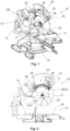
- the Figures 1 and 2 show a sawing device 10 with a circular disk-shaped saw blade 12.
- the sawing device 10 is a cross-cut saw.
- the sawing device 10 comprises a base assembly 14 and an arm assembly 16 rotatably mounted thereon.
- the base assembly 14 has a support surface 18 on which a component to be processed, i.e. to be sawn off or sawn in, can be positioned.
- the saw blade 12 can be set in rotation about a central axis A by actuating a drive motor M coupled to it and can be brought into interaction with the component to be machined by displacing the arm assembly 16 relative to the base assembly 14.
- the arm assembly 16 is shifted relative to the base assembly 14 manually in the example shown.
- the arm assembly 16 or, more generally speaking, the sawing device 10 comprises a frame 20 on which a drive shaft 22 is mounted in a rotationally drivable manner.
- the drive shaft 22 is drivingly coupled to the drive motor M.
- the saw blade 12 is fixed on the drive shaft 22, so that the saw blade 12 can be driven in rotation in a known manner.
- the sawing device 10 is also equipped with an emergency brake unit 24, which is in the Figures 3 and 4 can be seen in detail.
- a housing part is not shown.
- such a housing part serves to remove workpiece particles, for example sawdust or dust, which are generated by using the sawing device 10.
- a section of the handle provided at the end of the arm assembly 16 is formed by means of such a housing part.
- the housing part serves to cover the saw blade 12.
- the emergency brake unit 24 comprises a blocking element 26, which is rotatably mounted on the sawing device 10 via a bearing element 28 fixed to the frame 20 in the form of a fixed bearing pin 30 in such a way that it can selectively engage in the saw blade 12 to brake the saw blade 12.
- the emergency brake unit 24 includes an actuator unit 32, which is designed to selectively bring the blocking element 26 into engagement with the saw blade 12.
- the actuator unit 32 includes an electrically controllable lifting magnet, which is not shown in more detail in the figures.
- the emergency brake unit 24 also includes an associated control unit 34.
- control unit 34 is designed and arranged separately from the actuator unit 32 (see, for example, Figures 3 to 8 ).
- the actuator unit 32 and the control unit 34 are coupled via a signal line for signaling purposes.
- This configuration means that the actuator unit 32 and the control unit 34 can be dismantled separately from each other. This makes replacement, repair or maintenance easier.
- the control unit 34 is coupled to a sensor unit known per se for detecting actual or imminent contact with the saw blade 12 by a user.
- the actuator unit 32 can thus be operated depending on a detection result of the sensor unit.
- the emergency brake unit 24 also has a guide element 36, which is mounted on the frame 20 and guides a movement of the blocking element 26 along a guide direction F, as will be explained in detail below.
- the blocking element 26 is located in the Figures 3 and 4 in a normal position. In this position, the blocking element is arranged parallel to a circumferential direction U of the saw blade 12.
- the blocking element 26 is made up of three sections.
- the blocking element 26 includes a bearing section 38.
- the bearing section 38 is sleeve-shaped, i.e. the bearing section 38 comprises a circular cylindrical bearing opening 40, which is delimited by a wall 41 with a substantially constant wall thickness.
- the fixed bearing pin 30 is accommodated in the bearing opening 40, so that the blocking element 26 is rotatably mounted on the frame 20 of the sawing device 10 via the bearing section 38 and the bearing pin 30.
- the blocking element 26 further comprises a head section 42.
- the head section 42 is provided at an end of the blocking element 26 opposite the bearing section 38.
- the head section 42 is designed to engage in the saw blade 12 when the emergency brake unit 24 is actuated, i.e. driven by the actuator unit 32, in order to ideally brake it to a standstill.
- the head section 42 includes a coupling section 44.
- the coupling section 44 is positioned at an end of the blocking element 26 opposite the bearing section 38.
- the coupling section 44 is also positioned radially on the outside of the head section 42.
- the coupling section 44 serves two different functions.
- the coupling section 44 is designed to introduce an actuating force generated by the actuator unit 32 into the blocking element 26, so that the head section 42 can engage in the saw blade 12.
- the coupling section 44 serves to hold the blocking element 26 at least in the in Figures 3 and 4 to fix or lock the normal position shown relative to the frame 20.
- the head section 42 is thus prevented from engaging with the saw blade 12 in the normal position.
- the coupling section 44 includes two coupling openings 46.
- a U-shaped positive locking element 48 is provided, which is fastened on the one hand to the actuator unit 32, e.g. B. positively, and on the other hand has complementary knobs to the coupling openings 46, which engage in the coupling openings 46.
- the form-fitting element 48 is therefore positively coupled to both the blocking element 26 and the actuator unit 32.
- an actuating force generated by the actuator unit 32 can be introduced into the blocking element 26 via the positive locking element 48.
- the blocking element 26 is locked in the normal position relative to the frame 20 via the positive locking element 48 and the actuator unit 32.
- the coupling openings 46 and the associated knobs can also be omitted.
- a likewise U-shaped clamping element is used, which is clamped on the coupling section 44, ie is non-positively connected to the blocking element 26 in the area of the coupling section 44.
- Such a clamping element can be fastened to the actuator unit 32 in a form-fitting or non-positive manner.
- the head section 42 further comprises an incision zone 50.
- the incision zone 50 is characterized by a two-row pattern of through openings 52.
- the incision zone 50 is characterized by a two-row pattern of through openings 52.
- the material of the head section 42 is specifically weakened in the area of the incision zone 50, so that after the emergency brake unit 24 is triggered, the saw blade 12 cuts into the head section 42 gently and over as large an area as possible.
- connection zone 54 is provided essentially between the coupling section 44 and the incision zone 50.
- connection zone 54 also includes through openings 56. Again, for better clarity, only some of the through openings 56 are provided with a reference number in the figures. However, the diameters of the through openings 56 of the connection zone 54 are chosen to be significantly larger than the diameters of the through openings 52 of the incision zone 50.
- connection zone 54 serves, on the one hand, to transmit an actuating force from the coupling section 44 into the incision zone 50.
- the incision zone 50 is coupled to the deformation section to be explained below via the connection zone 54.
- connection zone 54 serve to ensure sufficient rigidity of the connection zone 54 with the lowest possible mass and thus the lowest possible mass inertia.
- the head section 42 is equipped with a guide surface 58.
- the guide surface 58 rests on a guide counter surface 60 of the guide element 36.
- the head section 42 Due to the geometry of the head section 42 and the guide counter surface 60, the head section 42 is subjected to a force in the direction of the saw blade 12 when it is shown in the illustration Figure 4 is moved clockwise along the circumferential direction U of the saw blade 12.
- the guide surface 58 has a normal with an extension component radially outwards.
- through openings are used in the head section 42 shown in the figures in order to create areas of different rigidity and different resistance to cutting by the saw blade 12. It goes without saying that, as an alternative to the through openings, this can also be achieved by providing different materials in the different areas of the head section 42. In this context, it may be particularly important to use materials of different ductility.
- the blocking element 26 Lying between the head section 42 and the bearing section 38, the blocking element 26 comprises a deformation section 64.
- the deformation section 64 connects the bearing section 38 and the head section 42 with each other.
- the deformation section 64 is arcuate overall, in the exemplary embodiment shown it is arcuate.
- An arc circumferential direction 66 ie the curved longitudinal extension direction of the arcuate deformation section 64, runs essentially parallel to the circumferential direction U of the saw blade 12.
- an outer circumference of the saw blade 12 and the arcuate deformation section 64 also run concentrically, with the central axis A representing the center.
- the deformation section 64 extends in the in Figure 4 illustrated embodiment over a section of the arc circumferential direction 66 with a center angle of approximately 60 degrees.
- the circumferential extent of the deformation section 64 is therefore essentially twice the circumferential extent of the head section 42.
- the head section 42 is therefore circumferentially shorter than the deformation section 64.
- the deformation section 64 is many times longer.
- the deformation section 64 is further spaced from the outer circumference of the saw blade 12 in a radial direction with respect to the central axis A of the saw blade 12 than the head section 42 and the bearing section 38.
- both the head section 42 and the bearing section 38 project radially inwards with respect to the arc circumferential direction 66 relative to the deformation section 64.
- the radial distance D of the deformation section 64 from the saw blade 12 is selected so that it is greater than zero in all operating situations of the emergency braking unit 24. This also applies in particular to an end position of the blocking element 26, which will be explained later.
- the distance D of the deformation section 64 is selected so that it does not contact the outer circumference of the saw blade 12 in any operating situation.
- the deformation section 64 further comprises a structure 68 which is plastically deformable in the arc circumferential direction 66.
- this structure 68 is formed from a total of eleven ring segments 70.
- the ring segments 70 are arranged adjacently along the arc circumferential direction 66 with a slight overlap.
- Each of the ring segments 70 has a wall 72 with a substantially constant wall thickness t.
- the walls 72 each define an axially continuous cavity 74.
- the structure 68 which is plastically deformable in the arc circumferential direction 66, therefore comprises a total of eleven cavities 74 arranged adjacently along the arc circumferential direction 66.
- a filling material 76 is arranged in each of the three cavities 74 that are arranged adjacent to the bearing section 38.
- the filling material is a rubber material.
- the blocking element 26 is made of an aluminum alloy.
- the filling material 76 results in a different stiffness of the deformation section 64 in the area of the cavities 74 provided with the filling material 76 than in the area of the unfilled cavities 74.
- the deformation section 64 therefore comprises two areas with different stiffnesses or, more generally, a stiffness curve.
- the rigidity can be specifically adjusted by appropriate selection of the filling material 76 as well as the number and position of the cavities 74 filled with the filling material 76.
- the structure 68 causes a rigidity of the deformation section 64 along the arc circumferential direction 66 to be smaller than a rigidity of the head section 42.
- the structure 68 has target deformation points 78. These are located in the in Figure 4 illustrated embodiment in each of the sections of the ring segments 70 that project radially furthest inwards and radially furthest outwards.
- the deformation section 64 is therefore designed to be plastically shortened along the arc circumferential direction 66 in order to brake the saw blade 12. This will be explained below using the Figures 5 to 8 explained.
- the blocking element 26 is held in the normal position via the positive locking element 48 and the actuator unit 32.
- the position Figure 5 corresponds to the situation at 0 milliseconds in the diagram Figure 9 .
- the emergency brake unit 24 is triggered at zero milliseconds (0 ms). This results in the actuator unit 32 being actuated and the head section 42 being acted upon in the direction of the saw blade 12. In the exemplary embodiment shown, this is done via the positive locking element 48.
- the saw blade 12 has cut into the incision zone 50, so that a force coupling between the saw blade 12 and the blocking element 26 has arisen. Due to the clockwise rotation of the saw blade 12, the in Figure 6 At the time shown, the head section 42 already differs from the initial situation Figure 5 taken along a certain circumferential distance along the circumferential direction U of the saw blade 12.
- connection between the positive locking element 48 and the head section 42 can be separated and the connection between the positive locking element 48 and the actuator unit 32 can be maintained.
- the guide element 36 ensures that the blocking element 26 cannot escape being driven by the saw blade 12 either in the radial direction or in the axial direction.
- the blocking element 26 is therefore guided along the guide direction F by means of the guide element 36.
- the entrainment by the saw blade 12 also caused at least those three ring segments 70 that are arranged adjacent to the head section 42 to be deformed.
- these ring segments were compressed along the arc circumferential direction 66.
- the emergency brake unit 24 is shown after another millisecond has elapsed, ie 2 milliseconds after triggering.
- the head section 42 is still coupled to the saw blade 12.
- the kinetic energy of the rotation of the saw blade 12 is converted into the plastic shortening of the deformation section 64 in order to brake the saw blade 12.
- Figure 8 the emergency brake unit 24 shows five milliseconds (5ms) after activation. At this point in time, the saw blade 12 is essentially stationary, ie it no longer rotates.
- the deformation section 64 is now essentially completely compressed, i.e. the cavities 74 are essentially closed by pushing the deformation section 64 together along the arc circumferential direction 66.
- the Figure 8 shows the emergency braking unit 24 at the end of an emergency braking process.
- the associated position of the blocking element 26 is also referred to as the end position.
- the blocking element 26 In order to be able to put the emergency brake unit 24 and the sawing device 10 into operation again, i.e. in order to make a sawing device 10 whose emergency brake unit 24 has been triggered ready for use again, the blocking element 26 must now be replaced.
- the blocking element 26 can optionally be removed from the frame 20 separately from the actuator unit 32.
- the blocking element 26 can therefore be dismantled in a single manner. This will be in conjunction with Figure 10 explained.
- the blocking element 26 is rotatably mounted on the frame 20 via the fixed bearing pin 30.
- a holding element 80 for holding the blocking element 26 on the bearing pin 30 is provided.
- this holding element 80 is a side wall section of the guide element 36, ie a section of a wall of the guide element 36, which prevents axial displacement of the blocking element 26.
- the guide element 36 is rotatably mounted on the frame 20 via a further bearing element 82, which is also designed as a bearing pin.
- the guide element 36 does not undesirably assume the release position, it can be locked in the operating position by means of a locking mechanism 84 (see next to Figure 10 also Figure 3 ).
- the locking mechanism 84 includes a first through opening 86 on the guide element 36 and a second through opening 88 on the frame 20.
- the locking mechanism 84 has a locking pin 90.
- the locking pin 90 is equipped with locking wings 92 at a first end and with an operating lever 93 at a second end opposite the first end.
- the locking pin 90 can thus be inserted into the through openings 86 and 88 and moved into a rotational position by means of the operating lever 93, in which the locking wings 92 engage behind a section of the frame 20.
- the guide element 36 can be selectively locked to the frame 20 and optionally unlocked from the frame 20. This of course also applies to the holding element 80 formed by the guide element 36.
- the bearing section 38 of the unused blocking element 26 is placed on the fixed bearing pin 30.
- the unused blocking element 26 is coupled to the actuator unit 32.
- the actuator unit 32 must be returned to its initial position. This can be done using the control unit 34.
- the head section 42 is always both selectively brought into engagement with the saw blade 12 by the actuator unit 32 and held in the normal position by the actuator unit 32 in such a way that the head section 42 does not inadvertently come into contact with the saw blade 12.
- the force is applied via a pressure piece coupled to the lifting magnet of the actuator unit 32, which is designed to apply an actuating force to the head section 42 in the direction of the saw blade 12.
- the pressure piece can be designed as a plunger.
- the blocking element 26 is held in the normal position by means of a spring-loaded pin 94.
- the spring-loaded pin 94 engages in an associated recess 96 on a circumferential end face of the blocking element 26.
- the actuator unit 32 corresponds to the actuator unit 32 of the embodiment from the Figures 1 to 10 . If this is triggered, it presses the blocking element 26 in the direction of the saw blade 12. As a result, the pin 94 is pressed out of the recess 96 against the spring force.
- a magnet 98 and a counterpart 100 made of ferromagnetic material are provided.
- the magnet is attached to the guide element 36 and the counterpart 100 to the head section 42 of the blocking element 26.
- the pairing of magnet 98 and counterpart 100 is selected such that the head section 42 and thus the counterpart 100 can be detached from the magnet 98 against a magnetic force by means of the actuator unit 32 when the emergency brake unit 24 is actuated.
- a leaf spring element 102 attached to the frame 20 via a first end.
- a second end of the leaf spring element 102 is accommodated in a recess 104 which is arranged on the front side of the blocking element 26. This keeps the blocking element 26 in the normal position.
- the actuator unit 32 again corresponds to the actuator unit 32 of the embodiment from the
- Figures 1 to 10 If this is triggered, it presses the blocking element 26 towards the saw blade 12. This deforms the leaf spring element 102 so that its free end jumps out of the recess 104 and releases the blocking element.
- the balls 106, 108 are spring-loaded so that they can be pushed out of the coupling openings 46 when the actuator unit 32 is actuated and can thus release the blocking element 26.
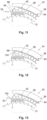
- the Figure 15 shows sections of an alternative sawing device 10.
- the deformation section 64 now includes hexagonal ring segments 70. This means that the walls of the 72 of the ring segments 70 each form hexagons and the through openings 74 defined by these walls 72 each have a hexagonal cross section.
- each of these rows of ring segments 70 also has 16 ring segments 70. There are therefore more ring segments 70 provided in each row than, for example, in the blocking element 26 Figure 4 .
- the plastically deformable structure 68 of the blocking element 26 Figure 15 can also be referred to as a honeycomb structure.
- the target deformation points 78 are now formed by those sections of the walls 72 of each ring segment 70 which include the corner of the hexagonal cross-section that projects radially furthest inward and the corner of the hexagonal cross-section that projects radially furthest outward.
- Each ring segment 70 therefore comprises two target deformation points 78, one radially inner and one radially outer.
- the through openings in the head section 42 more precisely the through openings 56 in the connection zone 54, now also have hexagonal cross sections. In addition, they are arranged slightly differently than in the blocking element 26 Figure 4 .
- Another alternative sawing device 10 shows sections Figure 16 .
- the sawing device 10 off Figure 16 has a significantly smaller saw blade 12 than the previously explained sawing devices.
- the blocking element 26 does not differ from the blocking element 26 in terms of its shape Figure 10 . It was only scaled proportionally.
- Another alternative sawing device 10 shows sections Figure 17 .
- the head section 42 of the blocking element 26 is designed differently.
- this is longer along the arc circumferential direction 66.
- the deformation section 64 is now made shorter. This now includes only a total of seven ring segments 70.
- the wall thickness t of the associated walls 72 was compared to the embodiment according to Figure 4 enlarged.
- An additional embodiment of a sawing device 10 shows Figure 18 .
- the sawing device 10 is now designed as a table saw.
- the actuator unit 32 can also be individually removable from the frame 20. This serves to easily repair the emergency brake unit 24 in the event that a defect occurs in the actuator unit 32.
- the actuator unit 32 can also be dismantled without tools.
Abstract
Es wird eine Sägevorrichtung (10) mit einem Rahmen, einem in Bezug auf den Rahmen drehbar gelagerten, kreisscheibenförmigen Sägeblatt (12) und einer Notbremseinheit (24) beschrieben. Die Notbremseinheit (24) umfasst ein Blockierelement (26), eine Aktuatoreinheit (32) sowie einer Steuerungseinheit (34). Das Blockierelement (26) weist einen Lagerabschnitt (38) und einen Kopfabschnitt (42) auf, der dazu ausgebildet ist, wahlweise zum Bremsen in das Sägeblatt (12) einzugreifen. Die Aktuatoreinheit (32) ist zumindest in einer Normalstellung des Blockierelements (26) derart mit dem Blockierelement (26) gekoppelt, dass das Blockierelement (26) mittels der Aktuatoreinheit (32) wahlweise in Eingriff mit dem Sägeblatt (12) bringbar ist. Zudem ist das Blockierelement (26) wahlweise separat von der Aktuatoreinheit (32) und/oder separat von der Steuerungseinheit (34) vom Rahmen demontierbar. Außerdem wird ein Verfahren zum Einsatzbereitmachen einer ausgelösten Notbremseinheit (24) einer Sägevorrichtung (10) vorgestellt. In diesem Zusammenhang wird ein Blockierelement (26) separat von der Aktuatoreinheit (32) und/oder separat von der Steuerungseinheit (34) demontiert und ein unbenutztes Blockierelement (26) montiert.A sawing device (10) is described with a frame, a circular disk-shaped saw blade (12) which is rotatably mounted with respect to the frame, and an emergency brake unit (24). The emergency brake unit (24) comprises a blocking element (26), an actuator unit (32) and a control unit (34). The blocking element (26) has a bearing section (38) and a head section (42), which is designed to selectively engage in the saw blade (12) for braking. The actuator unit (32) is coupled to the blocking element (26) at least in a normal position of the blocking element (26) in such a way that the blocking element (26) can be selectively brought into engagement with the saw blade (12) by means of the actuator unit (32). In addition, the blocking element (26) can optionally be removed from the frame separately from the actuator unit (32) and/or separately from the control unit (34). A method for making a triggered emergency brake unit (24) of a sawing device (10) ready for use is also presented. In this context, a blocking element (26) is dismantled separately from the actuator unit (32) and/or separately from the control unit (34) and an unused blocking element (26) is mounted.
Description
Die Erfindung betrifft eine Sägevorrichtung mit einem Rahmen, einem in Bezug auf den Rahmen drehbar gelagerten, kreisscheibenförmigen Sägeblatt und einer Notbremseinheit.The invention relates to a sawing device with a frame, a circular disk-shaped saw blade which is rotatably mounted with respect to the frame, and an emergency brake unit.
Außerdem ist die Erfindung auf ein Verfahren zum Einsatzbereitmachen einer ausgelösten Notbremseinheit einer Sägevorrichtung gerichtet.In addition, the invention is directed to a method for preparing a triggered emergency brake unit of a sawing device for use.
Sägevorrichtungen mit Notbremseinheiten sind aus dem Stand der Technik bekannt.Sawing devices with emergency braking units are known from the prior art.
Dabei dient die Notbremseinheit dazu, bei drohender oder bestehender Verletzungsgefahr eine Rotation des Sägeblatts zu stoppen. Auf diese Weise werden Verletzungen von Nutzern der Sägevorrichtungen vermieden oder zumindest in ihrer Schwere reduziert. Mit anderen Worten wird ein sicherer Betrieb der Sägevorrichtung gewährleistet.The emergency brake unit serves to stop the rotation of the saw blade if there is an impending or existing risk of injury. In this way, injuries to users of the sawing devices are avoided or at least reduced in severity. In other words, safe operation of the sawing device is guaranteed.
Insbesondere in Anwendungsfällen, in denen mit einer vergleichsweise häufigen Auslösung der Notbremseinheit zu rechnen ist, ist es im Sinne der Arbeitseffizienz wichtig, dass eine Säge mit einer ausgelösten Notbremseinheit schnell und einfach wieder Einsatzbereit gemacht werden kann. Nur dann kann zeitnah an der Bearbeitungsaufgabe weitergearbeitet werden. Auf diese Weise kann ein sicherer Betrieb der Sägevorrichtung mit einer hohen Arbeitseffizienz kombiniert werden. Aus wirtschaftlicher Sicht sollen außerdem durch das Auslösen der Notbremseinheit und das Einsatzbereitmachen einer ausgelösten Notbremseinheit möglichst geringe Kosten entstehen.Particularly in applications in which the emergency brake unit is expected to be triggered comparatively frequently, it is important in the interests of work efficiency that a saw with a triggered emergency brake unit can be made ready for use again quickly and easily. Only then can you continue working on the processing task in a timely manner. In this way, safe operation of the sawing device can be combined with high work efficiency. From an economic point of view, the costs of triggering the emergency braking unit and making a triggered emergency braking unit ready for use should also be as low as possible.
Es ist daher die Aufgabe der vorliegenden Erfindung, Sägevorrichtungen sowie zugehörige Verfahren zum Einsatzbereitmachen einer ausgelösten Notbremseinheit dahingehend zu
AS:TOP
verbessern, dass bei bekannt hoher Betriebssicherheit eine gesteigerte Arbeitseffizienz erreicht werden kann.It is therefore the object of the present invention to provide sawing devices and associated methods for making a triggered emergency brake unit ready for use
AS:TOP
improve so that increased work efficiency can be achieved with a known high level of operational reliability.
Die Aufgabe wird durch eine Sägevorrichtung mit einem Rahmen, einem in Bezug auf den Rahmen drehbar gelagerten, kreisscheibenförmigen Sägeblatt und einer Notbremseinheit gelöst. Die Notbremseinheit umfasst ein Blockierelement, eine Aktuatoreinheit sowie eine Steuerungseinheit, welche mit der Aktuatoreinheit integral ausgebildet oder signaltechnisch mit der Aktuatoreinheit gekoppelt ist. Das Blockierelement umfasst einen Lagerabschnitt, über den das Blockierelement am Rahmen gelagert ist, und einen Kopfabschnitt. Der Kopfabschnitt ist dazu ausgebildet, wahlweise zum Bremsen in das Sägeblatt einzugreifen. Dabei ist die Aktuatoreinheit zumindest in einer Normalstellung des Blockierelements derart mit dem Blockierelement gekoppelt, dass das Blockierelement mittels der Aktuatoreinheit wahlweise in Eingriff mit dem Sägeblatt bringbar ist. Zudem ist das Blockierelement wahlweise separat von der Aktuatoreinheit und/oder separat von der Steuerungseinheit vom Rahmen demontierbar. Vorliegend ist die Normalstellung des Blockierelements als diejenige Stellung zu verstehen, in der es noch nicht ins Sägeblatt eingegriffen hat. Die Normalstellung kann daher auch als unausgelöste Stellung bezeichnet werden. Darüber hinaus bedeutet separat von der Aktuatoreinheit und/oder separat von der Steuerungseinheit demontierbar, dass das Blockierelement von der Sägevorrichtung demontierbar ist, ohne dass gleichzeitig die Aktuatoreinheit und/oder die Steuerungseinheit der Notbremseinheit demontiert werden muss bzw. müssen. Hiervon nicht umfasst sind selbstverständlich Montageelemente, Lagerelemente, Halteelemente und Befestigungselemente, mittels derer das Blockierelement montiert ist. Mit anderen Worten ist das Blockierelement bezüglich der Aktuatoreinheit und/oder der Steuerungseinheit singulär demontierbar. Somit kann das Blockierelement alleine oder singulär ausgetauscht werden. Die Aktuatoreinheit und/oder die Steuerungseinheit bleiben bzw. bleibt bei einem derartigen Austausch an der Sägevorrichtung montiert. Dadurch kann das Blockierelement schnell und einfach demontiert werden. Das gilt prinzipiell für alle Betriebszustände der Sägevorrichtung und der Notbremseinheit, insbesondere jedoch für einen Zustand nach einer Auslösung der Notbremseinheit, d. h. wenn das Blockierelement ins Sägeblatt eingreift oder ins Sägeblatt eingegriffen hat. Somit lassen sich die Notbremseinheit und die Sägevorrichtung nach dem Auslösen der Notbremseinheit schnell und einfach wieder in Betrieb nehmen. Eine Bearbeitungsaufgabe kann so zeitnah weitergeführt und erledigt werden. Die Tatsache, dass das Blockierelement singulär ausgetauscht werden kann, bewirkt zudem, dass das Auslösen der Notbremseinheit und das Einsatzbereitmachen der ausgelösten Notbremseinheit vergleichsweise wenige Kosten verursacht.The task is solved by a sawing device with a frame, a circular disk-shaped saw blade which is rotatably mounted in relation to the frame and an emergency brake unit. The emergency brake unit comprises a blocking element, an actuator unit and a control unit, which is designed integrally with the actuator unit or is coupled to the actuator unit in terms of signaling. The blocking element comprises a bearing section, via which the blocking element is mounted on the frame, and a head section. The head section is designed to selectively engage in the saw blade for braking. The actuator unit is coupled to the blocking element at least in a normal position of the blocking element in such a way that the blocking element can be selectively brought into engagement with the saw blade by means of the actuator unit. In addition, the blocking element can optionally be removed from the frame separately from the actuator unit and/or separately from the control unit. In the present case, the normal position of the blocking element is to be understood as the position in which it has not yet engaged with the saw blade. The normal position can therefore also be referred to as the untriggered position. In addition, dismantled separately from the actuator unit and/or separately from the control unit means that the blocking element can be dismantled from the sawing device without the actuator unit and/or the control unit of the emergency brake unit having to be dismantled at the same time. Of course, this does not include mounting elements, bearing elements, holding elements and fastening elements by means of which the blocking element is mounted. In other words, the blocking element can be individually dismantled with respect to the actuator unit and/or the control unit. The blocking element can therefore be replaced alone or individually. The actuator unit and/or the control unit remain mounted on the sawing device during such an exchange. This means that the blocking element can be dismantled quickly and easily. This applies in principle to all operating states of the sawing device and the emergency brake unit, but in particular to a state after the emergency brake unit has been triggered, ie when the blocking element is in the Saw blade engages or has engaged the saw blade. This means that the emergency brake unit and the sawing device can be put back into operation quickly and easily after the emergency brake unit has been triggered. This means that a processing task can be continued and completed in a timely manner. The fact that the blocking element can be individually replaced also means that triggering the emergency brake unit and making the triggered emergency brake unit ready for use incurs comparatively few costs.
In einer bevorzugten Ausführungsform ist das Blockierelement separat von allen übrigen Komponenten der Notbremseinheit demontierbar. Mit anderen Worten ist das Blockierelement bezüglich aller übrigen Komponenten der Notbremseinheit singulär demontierbar. Die erläuterten Effekte und Vorteile ergeben sich dabei in besonders hohem Maße.In a preferred embodiment, the blocking element can be dismantled separately from all other components of the emergency brake unit. In other words, the blocking element can be individually dismantled with respect to all other components of the emergency brake unit. The effects and advantages explained are particularly high.
In einer weiteren bevorzugten Ausführungsform sind das Blockierelement, die Aktuatoreinheit und die Steuerungseinheit der Notbremseinheit jeweils separat von allen übrigen Komponenten der Notbremseinheit demontierbar. Mit anderen Worten ist das Blockierelement bezüglich aller übrigen Komponenten der Notbremseinheit singulär demontierbar. Zusätzlich ist die Aktuatoreinheit bezüglich aller übrigen Komponenten der Notbremseinheit singulär demontierbar. Außerdem ist die Steuerungseinheit der Notbremseinheit bezüglich aller übrigen Komponenten der Notbremseinheit singulär demontierbar. Somit können einzelne Komponenten der Notbremseinheit in einfacher Weise ausgetauscht, repariert und/oder gewartet werden.In a further preferred embodiment, the blocking element, the actuator unit and the control unit of the emergency brake unit can each be dismantled separately from all other components of the emergency brake unit. In other words, the blocking element can be individually dismantled with respect to all other components of the emergency brake unit. In addition, the actuator unit can be individually dismantled with respect to all other components of the emergency brake unit. In addition, the control unit of the emergency brake unit can be individually dismantled with respect to all other components of the emergency brake unit. Individual components of the emergency brake unit can therefore be easily replaced, repaired and/or maintained.
Die Steuerungseinheit der Notbremseinheit kann in einer ersten Alternative integral mit einer Motorsteuerungseinheit ausgebildet sein, die der Steuerung eines zum Antreiben des Sägeblatts ausgebildeten Antriebsmotors dient. In einer zweiten Alternative sind die Motorsteuerungseinheit und die Steuerungseinheit der Notbremseinheit separat ausgebildet. Sie können jedoch signaltechnisch miteinander verbunden sein, sodass der Antriebmotor beim Auslösen der Notbremseinheit einfach und zuverlässig deaktiviert werden kann.In a first alternative, the control unit of the emergency brake unit can be designed integrally with a motor control unit, which serves to control a drive motor designed to drive the saw blade. In a second alternative, the engine control unit and the control unit of the emergency brake unit are designed separately. However, they can be connected to one another in terms of signaling so that the drive motor can be deactivated easily and reliably when the emergency brake unit is triggered.
Die genannten Effekte und Vorteile der Erfindung werden im Vergleich zu bekannten Notbremseinheiten für Sägevorrichtungen besonders deutlich. Bei solchen Notbremseinheiten sind das Blockierelement, die zugehörige Aktuatoreinheit sowie die Steuerungseinheit als Modul gestaltet. Nach einem Auslösen der Notbremseinheit muss stets das gesamte Modul, d.h. sowohl das Blockierelement als auch die Aktuatoreinheit und die Steuerungseinheit, ersetzt werden.The effects and advantages of the invention mentioned are particularly clear in comparison to known emergency braking units for sawing devices. With such emergency braking units The blocking element, the associated actuator unit and the control unit are designed as a module. After the emergency brake unit is triggered, the entire module, ie both the blocking element and the actuator unit and the control unit, must always be replaced.
Eine Sägevorrichtung mit einem kreisscheibenförmigen Sägeblatt kann in diesem Zusammenhang auch als Kreissägevorrichtung oder schlicht als Kreissäge bezeichnet werden. Beispiele für solche Sägevorrichtungen sind Kappsägen, Tischkreissägen, Handkreissägen und Tauchsägen.In this context, a sawing device with a circular disk-shaped saw blade can also be referred to as a circular sawing device or simply as a circular saw. Examples of such sawing devices are cross-cut saws, table saws, hand-held circular saws and plunge saws.
Blockierelemente für Notbremseinheiten von Sägevorrichtungen werden umgangssprachlich auch als Bremskeile bezeichnet. Das ist unabhängig davon der Fall, ob das Blockierelement keilförmig ausgebildet ist oder als Keil wirkt.Blocking elements for emergency braking units of sawing devices are also colloquially referred to as brake wedges. This is the case regardless of whether the blocking element is wedge-shaped or acts as a wedge.
Es versteht sich zudem, dass die Notbremseinheit mit einer Sensoreinheit zum Erkennen einer tatsächlichen oder bevorstehenden Berührung des Sägeblatts durch einen Nutzer gekoppelt ist und in Abhängigkeit eines Detektionsergebnisses der Sensoreinheit betrieben wird. Auf diese Weise kann die Notbremseinheit rechtzeitig und zielgerichtet ausgelöst werden. Eine Verletzung des Nutzers der Sägevorrichtung kann so gänzlich verhindert oder zumindest in ihrer Schwere begrenzt werden.It is also understood that the emergency brake unit is coupled to a sensor unit for detecting an actual or imminent contact with the saw blade by a user and is operated depending on a detection result of the sensor unit. In this way, the emergency braking unit can be triggered in a timely and targeted manner. Injury to the user of the sawing device can be completely prevented or at least limited in severity.
Die Aktuatoreinheit der Notbremseinheit kann in diesem Zusammenhang einen Aktuator umfassen, der selektiv, insbesondere in Abhängigkeit des Detektionsergebnisses, ausgelöst werden kann. Mittels des Aktuators kann das Blockierelement, genauer gesagt der zugehörige Kopfabschnitt, schnell und zuverlässig in Eingriff mit dem Sägeblatt gebracht werden. Der Aktuator umfasst beispielsweise einen Hubmagneten oder einen Formgedächtnislegierungs-Aktuator. Auch ist es möglich, eine vorgespannte Feder, die mittels eines Schmelzdrahts freigegeben werden kann, als Aktuator zu verwenden.In this context, the actuator unit of the emergency brake unit can comprise an actuator that can be triggered selectively, in particular depending on the detection result. By means of the actuator, the blocking element, more precisely the associated head section, can be brought quickly and reliably into engagement with the saw blade. The actuator includes, for example, a lifting magnet or a shape memory alloy actuator. It is also possible to use a preloaded spring, which can be released using a fusible wire, as an actuator.
Die Sägevorrichtung kann ein Führungselement umfassen. Dabei ist das Führungselement zur Führung des Blockierelements zumindest entlang einer Führungsrichtung ausgebildet, die zumindest abschnittsweise parallel zu einer Umfangsrichtung des Sägeblatts verläuft. Das ist insbesondere dann von Bedeutung, wenn das Blockierelement mit seinem Kopfabschnitt ins Sägeblatt eingreift. In einer derartigen Situation muss die kinetische Energie der Rotation des Sägeblatts gezielt ins Blockierelement eingeleitet und vom Blockierelement aufgenommen werden. Das Führungselement verhindert dabei, dass sich das Blockierelement in unerwünschter Weise verformt oder verlagert. Eine Führung entlang einer Führungsrichtung, die zumindest abschnittsweise parallel zu einer Umfangsrichtung des Sägeblatts verläuft, erlaubt eine Bewegung des Blockierelements parallel zur Umfangsrichtung. Eine Bewegung parallel zu einer Axialrichtung des Sägeblatts wird durch das Führungselement unterbunden. Eine Bewegung in einer Richtung radial zum Sägeblatt kann je nach Anwendungsfall erlaubt oder unterbunden werden. Durch das Führungselement wird folglich erreicht, dass das Sägeblatt mit hoher Zuverlässigkeit mittels des Blockierelements gebremst wird.The sawing device can include a guide element. The guide element is designed to guide the blocking element at least along a guide direction which runs at least in sections parallel to a circumferential direction of the saw blade. That is This is particularly important when the blocking element engages the saw blade with its head section. In such a situation, the kinetic energy of the rotation of the saw blade must be specifically introduced into the blocking element and absorbed by the blocking element. The guide element prevents the blocking element from being deformed or displaced in an undesirable manner. A guide along a guide direction that runs at least in sections parallel to a circumferential direction of the saw blade allows the blocking element to move parallel to the circumferential direction. A movement parallel to an axial direction of the saw blade is prevented by the guide element. A movement in a direction radial to the saw blade can be permitted or prevented depending on the application. The guide element consequently ensures that the saw blade is braked with high reliability by means of the blocking element.
Gemäß einer Ausführungsform ist das Blockierelement über ein Lagerelement mit dem Rahmen verbunden. Das Lagerelement ist singulär von der Sägevorrichtung, d.h. vom Rahmen, demontierbar. Es sind in dieser Ausführungsform also sowohl das Lagerelement als auch das Blockierelement singulär demontierbar. Dabei bewirkt die singuläre Demontierbarkeit des Lagerelements die singuläre Demontierbarkeit des Blockierelements. Mit anderen Worten muss das Lagerelement demontiert werden, um das Blockierelement demontieren zu können. Weitere Komponenten der Notbremseinheit müssen weiterhin nicht demontiert werden. Durch das singulär demontierbare Lagerelement lässt sich das Blockierelement einerseits zuverlässig am Rahmen lagern, sodass auch vergleichsweise hohe Kräfte zwischen dem Blockierelement und dem Rahmen übertragen werden können. Andererseits bleibt das Blockierelement einfach und schnell demontierbar.According to one embodiment, the blocking element is connected to the frame via a bearing element. The bearing element can be individually removed from the sawing device, i.e. from the frame. In this embodiment, both the bearing element and the blocking element can be individually dismantled. The unique demountability of the bearing element causes the unique demountability of the blocking element. In other words, the bearing element must be dismantled in order to be able to dismantle the blocking element. Further components of the emergency brake unit do not need to be dismantled. On the one hand, the individually removable bearing element allows the blocking element to be reliably stored on the frame, so that comparatively high forces can also be transmitted between the blocking element and the frame. On the other hand, the blocking element remains easy and quick to dismantle.
Die Sägevorrichtung kann einen Verriegelungsmechanismus umfassen, mittels dem das Lagerelement wahlweise am Rahmen verriegelbar und wahlweise vom Rahmen entriegelbar ist. Das Lagerelement ist also derart am Rahmen gesichert, dass es sich nicht in unerwünschter Weise vom Rahmen trennt.The sawing device can include a locking mechanism by means of which the bearing element can be selectively locked to the frame and selectively unlocked from the frame. The bearing element is therefore secured to the frame in such a way that it does not separate from the frame in an undesirable manner.
Beispiele für Verriegelungsmechanismen umfassen ein Gewinde, in das das Lagerelement eingedreht ist, einen Exzentermechanismus, über den das Lagerelement festgeklemmt ist und Verriegelungsflügel, die an einem Ende des Lagerelements angeordnet sind und einen zugehörigen Rahmenabschnitt im verriegelten Zustand formschlüssig hintergreifen.Examples of locking mechanisms include a thread into which the bearing element is screwed, an eccentric mechanism via which the bearing element is clamped and locking wings which are arranged at one end of the bearing element and positively engage behind an associated frame section in the locked state.
In einer Variante ist das Führungselement mittels des Lagerelements am Rahmen gelagert. Das Lagerelement dient somit sowohl der Lagerung des Blockierelements als auch der Lagerung des Führungselements. Im Vergleich zu einer Lagerung des Blockierelements und des Führungselements mit jeweils separaten, spezifischen Lagerelementen können somit Bauteile eingespart werden. Dadurch lässt sich die Sägevorrichtung vergleichsweise einfach und kompakt aufbauen.In one variant, the guide element is mounted on the frame by means of the bearing element. The bearing element thus serves both to support the blocking element and to support the guide element. Compared to storing the blocking element and the guide element with separate, specific bearing elements, components can thus be saved. This allows the sawing device to be constructed in a comparatively simple and compact manner.
In einer anderen Alternative ist das Blockierelement mittels eines feststehenden Lagerelements am Rahmen gelagert. Zusätzlich ist ein Halteelement zum Halten des Blockierelements am Lagerelement vorgesehen. Über das feststehende Lagerelement lässt sich das Blockierelement zuverlässig am Rahmen lagern. Insbesondere können vergleichsweise hohe Kräfte zwischen dem Blockierelement und dem Rahmen übertragen werden. Zum Demontieren des Blockierelements muss lediglich das Halteelement demontiert oder in eine Freigabestellung überführt werden. Damit ist das Blockierelement einfach und schnell demontierbar.In another alternative, the blocking element is mounted on the frame by means of a fixed bearing element. In addition, a holding element is provided for holding the blocking element on the bearing element. The blocking element can be reliably stored on the frame using the fixed bearing element. In particular, comparatively high forces can be transmitted between the blocking element and the frame. To dismantle the blocking element, only the holding element has to be dismantled or moved into a release position. This means that the blocking element can be removed quickly and easily.
Auch kann das Halteelement wahlweise singulär vom Lagerelement demontierbar sein. Es sind in dieser Ausführungsform also sowohl das Halteelement als auch das Blockierelement singulär demontierbar. Dabei bewirkt die singuläre Demontierbarkeit des Halteelements die singuläre Demontierbarkeit des Blockierelements. Mit anderen Worten muss das Halteelement demontiert werden, um das Blockierelement demontieren zu können. Weitere Komponenten der Notbremseinheit müssen weiterhin nicht demontiert werden.The holding element can also be individually removable from the bearing element. In this embodiment, both the holding element and the blocking element can be individually dismantled. The unique demountability of the holding element causes the unique demountability of the blocking element. In other words, the holding element must be dismantled in order to be able to dismantle the blocking element. Further components of the emergency brake unit do not need to be dismantled.
Beispiele für Halteelemente umfassen eine Mutter, die auf das Lagerelement aufgedreht ist und Sicherungsringe, die form- oder kraftschlüssig mit dem Lagerelement gekoppelt sind.Examples of holding elements include a nut that is screwed onto the bearing element and locking rings that are positively or non-positively coupled to the bearing element.
In einem Ausführungsbeispiel ist das Halteelement durch einen Abschnitt des Führungselements gebildet. Es ist also ein Abschnitt des Führungselements dazu ausgebildet, das Blockierelement am Lagerelement zu halten. Insbesondere blockiert ein derartiger Abschnitt des Führungselements eine Bewegung des Blockierelements entlang einer Erstreckungsrichtung des Lagerelements, d.h. entlang einer Axialrichtung des Lagerelements. Das Führungselement kann in diesem Zusammenhang separat am Rahmen gelagert sein, sodass es wahlweise eine Betriebsstellung einnehmen kann, in der es das Blockierelement am Lagerelement hält und eine Freigabestellung einnehmen kann, in der es eine Demontage des Blockierelements vom Lagerelement freigibt.In one embodiment, the holding element is formed by a section of the guide element. A section of the guide element is therefore designed to to hold the blocking element on the bearing element. In particular, such a section of the guide element blocks a movement of the blocking element along an extension direction of the bearing element, ie along an axial direction of the bearing element. In this context, the guide element can be mounted separately on the frame, so that it can optionally assume an operating position in which it holds the blocking element on the bearing element and can assume a release position in which it enables the blocking element to be dismantled from the bearing element.
Das Lagerelement kann ein Lagerbolzen sein. Dabei kann das Blockierelement über den Lagerbolzen drehbar gelagert sein. Ein solches Lagerelement ist vergleichsweise einfach aufgebaut und kann das Blockierelement zuverlässig lagern. Durch die drehbare Lagerung wird erreicht, dass das Blockierelement einfach und zuverlässig in Eingriff mit dem Sägeblatt gebracht werden kann.The bearing element can be a bearing pin. The blocking element can be rotatably mounted via the bearing pin. Such a bearing element has a comparatively simple structure and can reliably store the blocking element. The rotatable bearing ensures that the blocking element can be easily and reliably brought into engagement with the saw blade.
In einer Ausführungsform umfasst das Blockierelement einen Koppelabschnitt, über den das Blockierelement zumindest in der Normalstellung mit der Aktuatoreinheit gekoppelt ist. Dabei kann der Koppelabschnitt an einem dem Lagerabschnitt entgegengesetzten Ende des Blockierelements positioniert sein. Über den Koppelabschnitt kann somit das Blockierelement mittels der Aktuatoreinheit wahlweise in Eingriff mit dem Sägeblatt gebracht werden. Durch die Positionierung des Koppelabschnitts an einem dem Lagerabschnitt entgegengesetzten Ende des Blockierelements wird erreicht, dass das Blockierelement mit hoher Zuverlässigkeit und Präzision ins Sägeblatt eingreifen kann. Unerwünschte Wechselwirkungen zwischen dem Koppelabschnitt und dem Lagerabschnitt werden dabei ausgeschlossen oder zumindest auf ein geringes Maß reduziert.In one embodiment, the blocking element comprises a coupling section via which the blocking element is coupled to the actuator unit at least in the normal position. The coupling section can be positioned at an end of the blocking element opposite the bearing section. The blocking element can thus be selectively brought into engagement with the saw blade by means of the actuator unit via the coupling section. Positioning the coupling section at an end of the blocking element opposite the bearing section ensures that the blocking element can engage with the saw blade with high reliability and precision. Undesirable interactions between the coupling section and the bearing section are excluded or at least reduced to a small extent.
In diesem Zusammenhang kann ein Klemmelement vorgesehen sein, das zumindest in der Normalstellung die Aktuatoreinheit kraftschlüssig mit dem Blockierelement koppelt. Alternativ kann ein Formschlusselement vorgesehen sein, das zumindest in der Normalstellung die Aktuatoreinheit formschlüssig mit dem Blockierelement koppelt. Die Aktuatoreinheit und das Blockierelement sind somit zumindest in der Normalstellung auf einfache und zuverlässige Weise gekoppelt. Eine derartige Kopplung lässt sich zudem im Zuge eines Austauschs des Blockierelements schnell und einfach lösen sowie wieder herstellen.In this context, a clamping element can be provided which, at least in the normal position, non-positively couples the actuator unit to the blocking element. Alternatively, a form-fitting element can be provided which, at least in the normal position, positively couples the actuator unit to the blocking element. The actuator unit and the blocking element are therefore simple and reliable, at least in the normal position coupled way. Such a coupling can also be released and restored quickly and easily when the blocking element is replaced.
In einer Endstellung kann das Blockierelement zumindest von einem Abschnitt der Aktuatoreinheit entkoppelt sein. Die Endstellung betrifft dabei eine Stellung des Blockierelements, nachdem es mittels der Aktuatoreinheit in Eingriff mit dem Sägeblatt gebracht wurde, d.h. eine Stellung nach Auslösung der Notbremseinheit. Aufgrund der bereits gelösten Kopplung zur Aktuatoreinheit lässt sich das Blockierelement besonders leicht von der Notbremseinheit demontieren und durch ein unbenutztes Blockierelement ersetzen.In an end position, the blocking element can be decoupled from at least a section of the actuator unit. The end position refers to a position of the blocking element after it has been brought into engagement with the saw blade by means of the actuator unit, i.e. a position after the emergency brake unit has been triggered. Because the coupling to the actuator unit has already been released, the blocking element can be particularly easily removed from the emergency brake unit and replaced with an unused blocking element.
Auch die Aktuatoreinheit kann wahlweise singulär vom Rahmen demontierbar sein. Wieder bezieht sich die singuläre Demontierbarkeit auf die übrigen Komponenten der Notbremseinheit. Damit lässt sich bei Bedarf die Aktuatoreinheit alleine austauschen, ohne dass gleichzeitig weitere Komponenten der Notbremseinheit demontiert werden müssen. Die Notbremseinheit ist somit besonders reparaturfreundlich. Es wird betont, dass in einer bevorzugten Ausführungsform die Aktuatoreinheit dazu ausgebildet ist, in einer Mehrzahl an Auslösevorgängen der Notbremseinheit benutzt zu werden. Standardmäßig muss also die Aktuatoreinheit nach dem Auslösen der Notbremseinheit nicht ausgetauscht werden.The actuator unit can also be individually removable from the frame. Again, the singular dismantling ability refers to the remaining components of the emergency brake unit. If necessary, the actuator unit alone can be replaced without having to dismantle other components of the emergency brake unit at the same time. The emergency brake unit is therefore particularly easy to repair. It is emphasized that in a preferred embodiment the actuator unit is designed to be used in a plurality of triggering processes of the emergency brake unit. By default, the actuator unit does not have to be replaced after the emergency brake unit has been triggered.
Bevorzugt ist wenigstens eines aus Blockierelement und Aktuatoreinheit werkzeugfrei demontierbar. Anders gesagt kann wenigstens eines aus Blockierelement und Aktuatoreinheit von Hand, insbesondere werkzeuglos, demontiert werden. Dadurch ist die Demontage besonders einfach.Preferably, at least one of the blocking element and the actuator unit can be removed without tools. In other words, at least one of the blocking element and the actuator unit can be dismantled by hand, in particular without tools. This makes dismantling particularly easy.
Gemäß einer Variante haben in der Normalstellung der Lagerabschnitt und der Kopfabschnitt im Wesentlichen den gleichen Abstand von einer Mittelachse des Sägeblatts. Folglich ist das Blockierelement einerseits platzsparend innerhalb der Sägevorrichtung angeordnet und andererseits so positioniert, dass der Kopfabschnitt des Blockierelements nur einen vergleichsweise kleinen Abstand überwinden muss, um ins Sägeblatt einzugreifen. Ferner lassen sich durch eine derartige Anordnung ins Blockierelement eingeleitete Kräfte zuverlässig über dessen Lagerabschnitt abstützen. Insgesamt kann das Sägeblatt vergleichsweise schnell und zuverlässig zum Stillstand gebracht werden.According to a variant, in the normal position, the bearing section and the head section are essentially the same distance from a central axis of the saw blade. Consequently, the blocking element is, on the one hand, arranged in a space-saving manner within the sawing device and, on the other hand, positioned so that the head section of the blocking element only has to overcome a comparatively small distance in order to engage in the saw blade. Furthermore, such an arrangement can reliably introduce forces into the blocking element support over its bearing section. Overall, the saw blade can be brought to a standstill comparatively quickly and reliably.
Zudem kann vorgesehen sein, dass das Blockierelement einen Verformungsabschnitt umfasst, der zwischen dem Lagerabschnitt und dem Kopfabschnitt liegt und/oder den Lagerabschnitt und den Kopfabschnitt miteinander verbindet. Der Verformungsabschnitt kann bogenförmig und dazu ausgebildet sein, zum Bremsen des Sägeblatts entlang einer Bogenumfangsrichtung plastisch verkürzt zu werden. Es kann somit die kinetische Energie der Rotation des Sägeblatts zuverlässig und zielgerichtet in eine plastische Verkürzung des Verformungsabschnitts umgesetzt werden. Das wird insbesondere durch die Bogenform des Verformungsabschnitts und seine Lage zwischen dem Lagerabschnitt und dem Kopfabschnitt bewirkt. Daher lässt sich eine Rotation des Sägeblatts in vergleichsweise kurzer Zeit stoppen. Nachdem der Verformungsabschnitt speziell dazu ausgebildet ist, entlang der Bogenumfangsrichtung plastisch verkürzt zu werden, kann er mit Bezug auf den durch den Verformungsabschnitt beanspruchten Bauraum vergleichsweise viel kinetische Energie aufnehmen und in eine plastische Verkürzung umsetzen. Das bedeutet auch, dass aus dem Abbremsen des Sägeblatts resultierende Kräfte zuverlässig und gezielt vom Verformungsabschnitt aufgenommen werden. Dadurch wirken auf die übrigen Komponenten der Notbremseinheit nur vergleichsweise geringe Kräfte. Dasselbe gilt für Komponenten der Sägevorrichtung. Folglich werden die übrigen Komponenten der Notbremseinheit sowie die Komponenten der Sägevorrichtung durch einen mittels des Blockierelements herbeigeführten Bremsvorgang nicht in ihrer Funktionstüchtigkeit beeinflusst. Das gilt insbesondere für das Sägeblatt, das bei einer Wiederinbetriebnahme der Sägevorrichtung weiterverwendet werden kann.In addition, it can be provided that the blocking element comprises a deformation section which lies between the bearing section and the head section and/or connects the bearing section and the head section to one another. The deformation section can be arcuate and designed to be plastically shortened along an arc circumferential direction in order to brake the saw blade. The kinetic energy of the rotation of the saw blade can therefore be reliably and specifically converted into a plastic shortening of the deformation section. This is caused in particular by the arcuate shape of the deformation section and its position between the bearing section and the head section. Therefore, rotation of the saw blade can be stopped in a comparatively short time. Since the deformation section is specifically designed to be plastically shortened along the circumferential direction of the arch, it can absorb a comparatively large amount of kinetic energy with respect to the installation space required by the deformation section and convert it into a plastic shortening. This also means that forces resulting from the braking of the saw blade are reliably and specifically absorbed by the deformation section. As a result, only comparatively small forces act on the other components of the emergency brake unit. The same applies to components of the sawing device. Consequently, the functionality of the remaining components of the emergency braking unit and the components of the sawing device are not affected by a braking process brought about by means of the blocking element. This applies in particular to the saw blade, which can continue to be used when the sawing device is put back into operation.
Bevorzugt verläuft der bogenförmige Verformungsabschnitt konzentrisch zum kreisscheibenförmigen Sägeblatt.The arcuate deformation section preferably runs concentrically to the circular disk-shaped saw blade.
Ferner wird die Aufgabe durch ein Verfahren zum Einsatzbereitmachen einer ausgelösten Notbremseinheit einer Sägevorrichtung gelöst. Die Sägevorrichtung umfasst ein kreisscheibenförmiges Sägeblatt. Die Notbremseinheit weist ein Blockierelement auf, das dazu ausgebildet ist, wahlweise in das Sägeblatt einzugreifen, um das Sägeblatt zu bremsen. Das Verfahren umfasst die folgenden Schritte:
- Demontieren des Blockierelements separat von einer Aktuatoreinheit der Notbremseinheit und/oder separat von einer Steuerungseinheit der Notbremseinheit, wobei das Blockierelement in das Sägeblatt eingreift oder mit dem Sägeblatt in Eingriff stand,
- Montieren eines unbenutzten Blockierelements.
- Dismantling the blocking element separately from an actuator unit of the emergency brake unit and / or separately from a control unit of the emergency brake unit, wherein the blocking element engages in the saw blade or was in engagement with the saw blade,
- Installing an unused blocking element.
In diesem Zusammenhang entsteht ein Zustand, in dem das Blockierelement in das Sägeblatt eingreift oder mit dem Sägeblatt in Eingriff stand, wenn die Notbremseinheit ausgelöst wurde und das Sägeblatt mittels des Blockierelements gebremst wurde. Bei Notbremseinheiten der hier relevanten Art muss infolge des Auslösens der Notbremseinheit das Blockierelement, welches durch das Auslösen beschädigt und/oder verformt wird, durch ein unbenutztes Blockierelement ersetzt werden. Wie bereits erwähnt, bedeutet vor diesem Hintergrund ein Demontieren des Blockierelements separat von einer Aktuatoreinheit der Notbremseinheit und/oder separat von einer Steuerungseinheit der Notbremseinheit, dass das Blockierelement von der Sägevorrichtung demontierbar ist, ohne dass gleichzeitig die Aktuatoreinheit der Notbremseinheit und/oder die Steuerungseinheit der Notbremseinheit demontiert werden müssen bzw. muss. Wie bereits erwähnt, fallen darunter keine Montageelemente, Lagerelemente, Halteelemente und Befestigungselemente, mittels derer das Blockierelement montiert ist. In diesem Zusammenhang kann auch von einem singulären Demontieren des Blockierelements gesprochen werden, wobei sich singulär wieder auf die Aktuatoreinheit und/oder die Steuerungseinheit der Notbremseinheit bezieht. Somit kann das Blockierelement alleine oder singulär ausgetauscht werden, um die Sägevorrichtung einsatzbereit zu machen. Die Aktuatoreinheit und/oder die Steuerungseinheit der Notbremseinheit bleiben bzw. bleibt bei einem derartigen Austausch an der Sägevorrichtung montiert. Das Blockierelement kann also schnell und einfach durch ein unbenutztes Blockierelement ausgetauscht werden. Somit lassen sich die Notbremseinheit und die Sägevorrichtung nach dem Auslösen der Notbremseinheit schnell und einfach einsatzbereit machen. Eine Bearbeitungsaufgabe kann dadurch zeitnah weitergeführt und erledigt werden. Die Tatsache, dass das Blockierelement singulär ausgetauscht werden kann, bewirkt zudem, dass das Auslösen der Notbremseinheit und das Einsatzbereitmachen der ausgelösten Notbremseinheit vergleichsweise wenige Kosten verursacht.In this context, a state arises in which the blocking element engages with the saw blade or was in engagement with the saw blade when the emergency brake unit was triggered and the saw blade was braked by means of the blocking element. In the case of emergency brake units of the type relevant here, as a result of the emergency brake unit being triggered, the blocking element, which is damaged and/or deformed by the triggering, must be replaced by an unused blocking element. As already mentioned, against this background, dismantling the blocking element separately from an actuator unit of the emergency brake unit and/or separately from a control unit of the emergency brake unit means that the blocking element can be dismantled from the sawing device without simultaneously removing the actuator unit of the emergency brake unit and/or the control unit The emergency brake unit must or must be dismantled. As already mentioned, this does not include mounting elements, bearing elements, holding elements and fastening elements by means of which the blocking element is mounted. In this context, one can also speak of a singular dismantling of the blocking element, with singular again referring to the actuator unit and/or the control unit of the emergency brake unit. The blocking element can therefore be replaced alone or individually in order to make the sawing device ready for use. The actuator unit and/or the control unit of the emergency brake unit remain or remains mounted on the sawing device during such a replacement. The blocking element can therefore be quickly and easily replaced with an unused blocking element. This means that the emergency brake unit and the sawing device can be made ready for use quickly and easily after the emergency brake unit has been triggered. A processing task can can therefore be continued and completed in a timely manner. The fact that the blocking element can be individually replaced also means that triggering the emergency brake unit and making the triggered emergency brake unit ready for use incurs comparatively few costs.
In einer bevorzugten Ausführungsform wird das Blockierelement separat von allen übrigen Komponenten der Notbremseinheit demontiert. Mit anderen Worten wird das Blockierelement bezüglich aller übrigen Komponenten der Notbremseinheit singulär demontiert. Die erläuterten Effekte und Vorteile ergeben sich dabei in besonders hohem Maße.In a preferred embodiment, the blocking element is dismantled separately from all other components of the emergency brake unit. In other words, the blocking element is dismantled individually with respect to all other components of the emergency brake unit. The effects and advantages explained are particularly high.
In einer weiteren bevorzugten Ausführungsform werden das Blockierelement, die Aktuatoreinheit und die Steuerungseinheit der Notbremseinheit jeweils separat von allen übrigen Komponenten der Notbremseinheit demontiert. Mit anderen Worten wird das Blockierelement bezüglich aller übrigen Komponenten der Notbremseinheit singulär demontiert. Zusätzlich wird die Aktuatoreinheit bezüglich aller übrigen Komponenten der Notbremseinheit singulär demontiert. Außerdem wird die Steuerungseinheit der Notbremseinheit bezüglich aller übrigen Komponenten der Notbremseinheit singulär demontiert. Folglich können einzelne Komponenten der Notbremseinheit in einfacher Weise ausgetauscht, repariert und/oder gewartet werden.In a further preferred embodiment, the blocking element, the actuator unit and the control unit of the emergency brake unit are each dismantled separately from all other components of the emergency brake unit. In other words, the blocking element is dismantled individually with respect to all other components of the emergency brake unit. In addition, the actuator unit is individually dismantled with respect to all other components of the emergency brake unit. In addition, the control unit of the emergency brake unit is individually dismantled with respect to all other components of the emergency brake unit. Consequently, individual components of the emergency brake unit can be easily replaced, repaired and/or maintained.
In einer Variante wird beim Montieren des unbenutzten Blockierelements das unbenutzte Blockierelement mit einer Aktuatoreinheit der Notbremseinheit gekoppelt. Es wird also nicht die Aktuatoreinheit getauscht. Durch das Koppeln kann in einem nachfolgenden Betrieb der Sägevorrichtung das Blockierelement mittels der Aktuatoreinheit wahlweise in Eingriff mit dem Sägeblatt gebracht werden.In one variant, when mounting the unused blocking element, the unused blocking element is coupled to an actuator unit of the emergency brake unit. So the actuator unit is not replaced. By coupling, the blocking element can be selectively brought into engagement with the saw blade by means of the actuator unit in a subsequent operation of the sawing device.
In einer Ausführungsform wird zum Demontieren des Blockierelements ein Lagerelement, mittels dem das Blockierelement in der Sägevorrichtung gelagert ist, demontiert. Alternativ wird ein Halteelement von einem feststehenden Lagerelement, mittels dem das Blockierelement in der Sägevorrichtung gelagert ist, entfernt. In beiden Varianten kann somit das Blockierelement schnell und einfach demontiert werden. Das kann bevorzugt werkzeugfrei erfolgen.In one embodiment, in order to dismantle the blocking element, a bearing element, by means of which the blocking element is mounted in the sawing device, is dismantled. Alternatively, a holding element is removed from a fixed bearing element, by means of which the blocking element is mounted in the sawing device. This can happen in both variants Blocking element can be dismantled quickly and easily. This can preferably be done without tools.
Dabei kann das Halteelement durch einen Abschnitt eines Führungselements gebildet sein und das Entfernen des Halteelements vom feststehenden Lagerelement ein Bewegen des Führungselements in eine Freigabestellung umfassen. Die Bewegung in die Freigabestellung umfasst beispielsweise ein Klappen, Schwenken, Drehen und/oder Schieben des Führungselements. Bevorzugt wird dabei das Führungselement nicht vom Rahmen der Sägevorrichtung getrennt. Auf diese Weise lässt sich das Halteelement besonders schnell und einfach vom feststehenden Lagerelement entfernen. Das Blockierelement lässt sich damit besonders schnell und einfach austauschen.The holding element can be formed by a section of a guide element and the removal of the holding element from the fixed bearing element can include moving the guide element into a release position. The movement into the release position includes, for example, folding, pivoting, rotating and/or pushing the guide element. The guide element is preferably not separated from the frame of the sawing device. In this way, the holding element can be removed from the fixed bearing element particularly quickly and easily. The blocking element can therefore be replaced particularly quickly and easily.
Die Erfindung wird nachstehend anhand verschiedener Ausführungsbeispiele erläutert, die in den beigefügten Zeichnungen gezeigt sind. Es zeigen:
Figur 1- eine erfindungsgemäße Sägevorrichtung in einer perspektivischen Ansicht, wobei die erfindungsgemäße Sägevorrichtung eine Notbremseinheit umfasst, die mit einem Blockierelement ausgestattet ist und mittels eines erfindungsgemäßen Verfahrens einsatzbereit gemacht werden kann,
Figur 2- die
Sägevorrichtung aus Figur 1 in einer Seitenansicht, wobei ein Führungselement der Notbremseinheit fortgelassen ist, Figur 3- Teile der Sägevorrichtung aus
den Figuren 1 und 2 in einer separaten Ansicht, Figur 4- eine Detailansicht des Blockierelements,
Figuren 5 bis 8- Teile der Sägevorrichtung aus
den Figuren 1 und 2 zu verschiedenen Zeitpunkten nach dem Auslösen der Notbremseinheit, - Figur 9
- einen Verlauf einer vom Blockierelement aufgenommenen Kraft über der Zeit nach dem Auslösen der Notbremseinheit,
Figur 10- Teile der Sägevorrichtung aus
den Figuren 1 und 2 beim Montieren des Blockierelements, - Figuren 11
bis 14 - alternative Ausführungen zum Halten des Blockierelements in einer Normal stellung,
- Figur 15
- Teile einer Sägevorrichtung gemäß einer alternativen Ausführungsform,
Figur 16- Teile einer Sägevorrichtung gemäß noch einer alternativen Ausführungsform,
- Figur 17
- Teile einer Sägevorrichtung gemäß einer weiteren alternativen Ausführungsform, und
Figur 18- eine zusätzliche Ausführungsform einer erfindungsgemäßen Sägevorrichtung.
- Figure 1
- a sawing device according to the invention in a perspective view, the sawing device according to the invention comprising an emergency brake unit which is equipped with a blocking element and can be made ready for use by means of a method according to the invention,
- Figure 2
- the sawing device
Figure 1 in a side view, with a guide element of the emergency brake unit omitted, - Figure 3
- Parts of the sawing device from the
Figures 1 and 2 in a separate view, - Figure 4
- a detailed view of the blocking element,
- Figures 5 to 8
- Parts of the sawing device from the
Figures 1 and 2 at different times after the emergency brake unit is triggered, - Figure 9
- a curve of a force absorbed by the blocking element over time after the emergency brake unit has been triggered,
- Figure 10
- Parts of the sawing device from the
Figures 1 and 2 when installing the blocking element, - Figures 11 to 14
- alternative versions for holding the blocking element in a normal position,
- Figure 15
- Parts of a sawing device according to an alternative embodiment,
- Figure 16
- Parts of a sawing device according to yet another alternative embodiment,
- Figure 17
- Parts of a sawing device according to a further alternative embodiment, and
- Figure 18
- an additional embodiment of a sawing device according to the invention.
Die
Die Sägevorrichtung 10 umfasst eine Basisbaugruppe 14 und eine drehbar daran gelagerte Armbaugruppe 16.The sawing
Die Basisbaugruppe 14 hat eine Auflagefläche 18, auf der ein zu bearbeitendes, d.h. abzusägendes oder einzusägendes, Bauteil positioniert werden kann.The
Ferner kann das Sägeblatt 12 durch Betätigung eines mit diesem gekoppelten Antriebsmotors M in Rotation um eine Mittelachse A versetzt werden und durch eine Verlagerung der Armbaugruppe 16 relativ zur Basisbaugruppe 14 mit dem zu bearbeitenden Bauteil in Wechselwirkung gebracht werden.Furthermore, the
Die Verlagerung der Armbaugruppe 16 relativ zur Basisbaugruppe 14 erfolgt im gezeigten Beispiel manuell.The
Dabei umfasst die Armbaugruppe 16 oder allgemeiner gesprochen die Sägevorrichtung 10 einen Rahmen 20, an dem eine Antriebswelle 22 drehantreibbar gelagert ist. Die Antriebswelle 22 ist antriebsmäßig mit dem Antriebsmotor M gekoppelt. Das Sägeblatt 12 ist auf der Antriebswelle 22 fixiert, sodass sich in bekannter Weise das Sägeblatt 12 drehantreiben lässt.The
Die Sägevorrichtung 10 ist ferner mit einer Notbremseinheit 24 ausgestattet, die in den
Zur besseren Sichtbarkeit der Notbremseinheit 24 ist in den
Die Notbremseinheit 24 umfasst ein Blockierelement 26, das über ein am Rahmen 20 feststehendes Lagerelement 28 in Form eines feststehenden Lagerbolzens 30 derart drehbar an der Sägevorrichtung 10 gelagert ist, dass es zum Bremsen des Sägeblatts 12 wahlweise in das Sägeblatt 12 eingreifen kann.The
Zudem umfasst die Notbremseinheit 24 eine Aktuatoreinheit 32, die dazu ausgebildet ist, das Blockierelement 26 wahlweise in Eingriff mit dem Sägeblatt 12 zu bringen.In addition, the
Im dargestellten Beispiel umfasst die Aktuatoreinheit 32 hierzu einen elektrisch ansteuerbaren Hubmagneten, der in den Figuren nicht näher dargestellt ist.In the example shown, the
Die Notbremseinheit 24 umfasst auch eine zugehörige Steuerungseinheit 34.The
In der dargestellten Ausführungsform ist die Steuerungseinheit 34 von der Aktuatoreinheit 32 getrennt ausgeführt und angeordnet (siehe z. B.
Diese Konfiguration bewirkt, dass die Aktuatoreinheit 32 und die Steuerungseinheit 34 separat voneinander demontiert werden können. Das erleichtert einen Austausch, eine Reparatur oder Wartung.This configuration means that the
Die Steuerungseinheit 34 ist mit einer an sich bekannten Sensoreinheit zum Erkennen einer tatsächlichen oder bevorstehenden Berührung des Sägeblatts 12 durch einen Nutzer gekoppelt.The
Somit lässt sich die Aktuatoreinheit 32 in Abhängigkeit eines Detektionsergebnisses der Sensoreinheit betreiben.The
Die Notbremseinheit 24 weist ferner ein Führungselement 36 auf, das am Rahmen 20 gelagert ist und eine Bewegung des Blockierelement 26 entlang einer Führungsrichtung F führt, wie nachfolgend noch im Detail erläutert werden wird.The
Das Blockierelement 26 befindet sich in den
Dabei ist das Blockierelement 26 aus drei Abschnitten aufgebaut.The blocking
Das Blockierelement 26 umfasst einen Lagerabschnitt 38.The blocking
In der dargestellten Ausführungsform ist der Lagerabschnitt 38 hülsenförmig, d.h. der Lagerabschnitt 38 umfasst eine kreiszylinderförmige Lageröffnung 40, die von einer Wandung 41 mit im Wesentlichen konstanter Wandstärke begrenzt ist.In the illustrated embodiment, the bearing
Der feststehende Lagerbolzen 30 ist in der Lageröffnung 40 aufgenommen, sodass das Blockierelement 26 über den Lagerabschnitt 38 und den Lagerbolzen 30 drehbar am Rahmen 20 der Sägevorrichtung 10 gelagert ist.The fixed bearing pin 30 is accommodated in the
Das Blockierelement 26 umfasst ferner einen Kopfabschnitt 42.The blocking
Der Kopfabschnitt 42 ist an einem dem Lagerabschnitt 38 entgegengesetzten Ende des Blockierelements 26 vorgesehen.The
Dabei ist der Kopfabschnitt 42 dazu ausgebildet, bei einer Betätigung der Notbremseinheit 24, d.h. angetrieben durch die Aktuatoreinheit 32, in das Sägeblatt 12 einzugreifen, um dieses idealerweise bis zum Stillstand abzubremsen.The
In diesem Zusammenhang umfasst der Kopfabschnitt 42 einen Koppelabschnitt 44.In this context, the
Der Koppelabschnitt 44 ist an einem dem Lagerabschnitt 38 entgegengesetzten Ende des Blockierelements 26 positioniert.The
Der Koppelabschnitt 44 ist zudem radial außen am Kopfabschnitt 42 positioniert.The
Der Koppelabschnitt 44 dient zwei unterschiedlichen Funktionen.The
Zum einen ist der Koppelabschnitt 44 dazu ausgebildet, eine von der Aktuatoreinheit 32 generierte Betätigungskraft in das Blockierelement 26 einzuleiten, sodass der Kopfabschnitt 42 ins Sägeblatt 12 eingreifen kann.On the one hand, the
Zum anderen dient der Koppelabschnitt 44 dazu, das Blockierelement 26 zumindest in der in
Die Funktionen der Krafteinleitung und der Arretierung können dabei separat voneinander oder gemeinsam, d.h. kombiniert, umgesetzt sein. Letzteres ist bei den Ausführungsformen gemäß
Hier umfasst der Koppelabschnitt 44 zwei Koppelöffnungen 46.Here the
Zudem ist ein U-förmiges Formschlusselement 48 vorgesehen, welches einerseits an der Aktuatoreinheit 32 befestigt ist, z. B. formschlüssig, und das andererseits zu den Koppelöffnungen 46 komplementäre Noppen aufweist, die in die Koppelöffnungen 46 eingreifen. Das Formschlusselement 48 ist also formschlüssig sowohl mit dem Blockierelement 26 als auch mit der Aktuatoreinheit 32 gekoppelt.In addition, a U-shaped
Somit kann über das Formschlusselement 48 einerseits eine von der Aktuatoreinheit 32 generierte Betätigungskraft in das Blockierelement 26 eingeleitet werden. Andererseits wird das Blockierelement 26 über das Formschlusselement 48 und die Aktuatoreinheit 32 in der Normalstellung relativ zum Rahmen 20 arretiert.Thus, on the one hand, an actuating force generated by the
Es versteht sich dabei, dass alternativ die Koppelöffnungen 46 und die zugeordneten Noppen auch weggelassen werden können. Anstelle des U-förmigen Formschlusselements 48 wird dann ein ebenfalls U-förmiges Klemmelement verwendet, das auf dem Koppelabschnitt 44 festgeklemmt, d.h. im Bereich des Koppelabschnitts 44 kraftschlüssig mit dem Blockierelement 26 verbunden, ist. Die Befestigung eines solchen Klemmelements an der Aktuatoreinheit 32 kann formschlüssig oder kraftschlüssig erfolgen.It goes without saying that, alternatively, the
Der Kopfabschnitt 42 umfasst ferner eine Einschnittzone 50.The
In der dargestellten Ausführungsform ist die Einschnittzone 50 durch ein zweireihiges Muster an Durchgangsöffnungen 52 charakterisiert. Der besseren Übersichtlichkeit wegen sind in denIn the illustrated embodiment, the
Figuren nur einige der Durchgangsöffnungen 52 mit einem Bezugszeichen versehen.Figures only provide some of the through
Mittels der Durchgangsöffnungen 52 wird das Material des Kopfabschnitts 42 im Bereich der Einschnittzone 50 gezielt geschwächt, sodass nach einer Auslösung der Notbremseinheit 24 das Sägeblatt 12 sanft und über einen möglichst großen Bereich des Kopfabschnitts 42 in diesen einschneidet.By means of the through
Dadurch ergibt sich eine zuverlässige Kopplung zwischen dem Sägeblatt 12 und dem Blockierelement 26, die zum zuverlässigen Abbremsen einer Rotation des Sägeblatts 12 notwendig ist.This results in a reliable coupling between the
Im Wesentlichen zwischen dem Koppelabschnitt 44 und der Einschnittzone 50 ist eine Anbindungszone 54 vorgesehen.A
In der dargestellten Ausführungsform umfasst auch die Anbindungszone 54 Durchgangsöffnungen 56. Wieder sind der besseren Übersichtlichkeit wegen in den Figuren nur einige der Durchgangsöffnungen 56 mit einem Bezugszeichen versehen. Dabei sind jedoch die Durchmesser der Durchgangsöffnungen 56 der Anbindungszone 54 deutlich größer gewählt als die Durchmesser der Durchgangsöffnungen 52 der Einschnittzone 50.In the embodiment shown, the
Die Anbindungszone 54 dient dazu, einerseits eine Betätigungskraft vom Koppelabschnitt 44 in die Einschnittzone 50 zu übertragen. Andererseits wird über die Anbindungszone 54 die Einschnittzone 50 mit dem nachfolgend noch zu erläuternden Verformungsabschnitt gekoppelt.The
Die Durchgangsöffnungen 56 der Anbindungszone 54 dienen in diesem Zusammenhang dazu, eine ausreichende Steifigkeit der Anbindungszone 54 bei möglichst niedriger Masse und damit möglichst niedriger Massenträgheit zu gewährleisten.In this context, the through
Außerdem ist der Kopfabschnitt 42 mit einer Führungsfläche 58 ausgestattet.In addition, the
Die Führungsfläche 58 liegt an einer Führungsgegenfläche 60 des Führungselements 36 an.The
Aufgrund der Geometrie des Kopfabschnitts 42 und der Führungsgegenfläche 60 wird der Kopfabschnitt 42 mit einer Kraft in Richtung des Sägeblatts 12 beaufschlagt, wenn er in der Darstellung gemäß
Wie anhand der vorstehenden Erläuterungen deutlich wird, werden beim in den Figuren gezeigten Kopfabschnitt 42 Durchgangsöffnungen verwendet, um Bereiche unterschiedlicher Steifigkeit und unterschiedlicher Widerstände gegenüber dem Einschneiden durch das Sägeblatt 12 zu schaffen. Es versteht sich, dass dies alternativ zu den Durchgangsöffnungen auch dadurch erreicht werden kann, dass in den verschiedenen Bereichen des Kopfabschnitts 42 unterschiedliche Materialien vorgesehen werden. In diesem Zusammenhang kann es insbesondere darauf ankommen, Materialien unterschiedlicher Duktilität zu verwenden.As is clear from the above explanations, through openings are used in the
Zwischen dem Kopfabschnitt 42 und dem Lagerabschnitt 38 liegend umfasst das Blockierelement 26 einen Verformungsabschnitt 64.Lying between the
Der Verformungsabschnitt 64 verbindet den Lagerabschnitt 38 und den Kopfabschnitt 42 miteinander.The
Der Verformungsabschnitt 64 ist insgesamt bogenförmig, im dargestellten Ausführungsbeispiel kreisbogenförmig.The
Dabei verläuft eine Bogenumfangsrichtung 66, d.h. die gekrümmt verlaufende Längserstreckungsrichtung des bogenförmigen Verformungsabschnitts 64 im Wesentlichen parallel zur Umfangsrichtung U des Sägeblatts 12.An arc
In der dargestellten Ausführungsform verlaufen ein Außenumfang des Sägeblatts 12 und der bogenförmige Verformungsabschnitt 64 zudem konzentrisch, wobei die Mittelachse A das Zentrum darstellt.In the illustrated embodiment, an outer circumference of the
Der Verformungsabschnitt 64 erstreckt sich dabei in der in
Die umfangsmäßige Erstreckung des Verformungsabschnitt 64 beträgt somit im Wesentlichen das Doppelte der umfangsmäßigen Erstreckung des Kopfabschnitts 42. Der Kopfabschnitt 42 ist folglich umfangsmäßig kürzer als der Verformungsabschnitt 64.The circumferential extent of the
Auch mit Bezug auf eine umfangsmäßige Erstreckung des Lagerabschnitts 38 ist der Verformungsabschnitt 64 um ein Vielfaches länger.Also with regard to a circumferential extent of the
Außerdem ist der Verformungsabschnitt 64 in einer bezüglich der Mittelachse A des Sägeblatts 12 radialen Richtung weiter vom Außenumfang des Sägeblatts 12 beabstandet als der Kopfabschnitt 42 und der Lagerabschnitt 38.In addition, the
Mit anderen Worten springen sowohl der Kopfabschnitt 42 als auch der Lagerabschnitt 38 bezüglich der Bogenumfangsrichtung 66 gegenüber dem Verformungsabschnitt 64 nach radial innen vor.In other words, both the
In diesem Zusammenhang ist der radiale Abstand D des Verformungsabschnitts 64 vom Sägeblatt 12 so gewählt, dass dieser in allen Betriebssituationen der Notbremseinheit 24 größer null ist. Das gilt insbesondere auch für eine später noch zu erläuternde Endstellung des Blockierelements 26.In this context, the radial distance D of the
Mit anderen Worten ist der Abstand D des Verformungsabschnitts 64 so gewählt, dass dieser in keiner Betriebssituation den Außenumfang des Sägeblatts 12 kontaktiert.In other words, the distance D of the
Der Verformungsabschnitt 64 umfasst weiter eine in der Bogenumfangsrichtung 66 plastisch verformbare Struktur 68.The
In der in der
Die Ringsegmente 70 sind entlang der Bogenumfangsrichtung 66 mit einer leichten Überlappung benachbart angeordnet.The
Jedes der Ringsegmente 70 hat eine Wand 72 mit einer im Wesentlichen konstanten Wandstärke t.Each of the
Dabei definieren die Wände 72 jeweils einen axial durchgehenden Hohlraum 74.The
Der besseren Übersichtlichkeit wegen sind in den Figuren nur einige der Ringsegmente 70 sowie nur einige der Wände 72 und einige der Hohlräume 74 mit einem Bezugszeichen versehen.For the sake of clarity, only some of the
Die in der Bogenumfangsrichtung 66 plastisch verformbare Struktur 68 umfasst also insgesamt elf entlang der Bogenumfangsrichtung 66 benachbart angeordnete Hohlräume 74.The
Aufgrund der leichten Überlappung der Ringsegmente 70 ergibt sich für jeden Hohlraum 74 ein sichelmondförmiger Querschnitt.Due to the slight overlap of the
Ferner ist im Inneren derjenigen drei Hohlräume 74, die benachbart zum Lagerabschnitt 38 angeordnet sind, jeweils ein Füllmaterial 76 angeordnet.Furthermore, a filling
In der dargestellten Ausführungsform handelt es sich beim Füllmaterial um ein Gummimaterial.In the embodiment shown, the filling material is a rubber material.
Im Übrigen ist das Blockierelement 26 aus einer Aluminiumlegierung hergestellt.Furthermore, the blocking
Durch das Füllmaterial 76 ergibt sich im Bereich der mit dem Füllmaterial 76 versehenen Hohlräume 74 eine andere Steifigkeit des Verformungsabschnitts 64 als im Bereich der ungefüllten Hohlräume 74. Der Verformungsabschnitt 64 umfasst also zwei Bereiche mit unterschiedlichen Steifigkeiten oder allgemeiner gesagt einen Steifigkeitsverlauf.The filling
Es versteht sich dabei, dass die Steifigkeit durch eine entsprechende Auswahl des Füllmaterials 76 sowie die Anzahl und Position der mit dem Füllmaterial 76 ausgefüllten Hohlräume 74 gezielt eingestellt werden kann.It goes without saying that the rigidity can be specifically adjusted by appropriate selection of the filling
Die Struktur 68 bewirkt insgesamt, dass eine Steifigkeit des Verformungsabschnitts 64 entlang der Bogenumfangsrichtung 66 kleiner ist als eine Steifigkeit des Kopfabschnitts 42.Overall, the
Zudem weist die Struktur 68 Soll-Verformungsstellen 78 auf. Diese befinden sich in der in
Der besseren Übersichtlichkeit wegen sind in den Figuren abermals nur einige der Soll-Verformungsstellen 78 mit einem Bezugszeichen versehen.For the sake of clarity, only some of the target deformation points 78 are provided with a reference number in the figures.
Der Verformungsabschnitt 64 ist folglich dazu ausgebildet, zum Bremsen des Sägeblatts 12 entlang der Bogenumfangsrichtung 66 plastisch verkürzt zu werden. Dies wird nachfolgend anhand der
In diesem Zusammenhang zeigt die
Dementsprechend wirkt auch noch keine Kraft auf das Blockierelement 26 (vgl.
Wie bereits erläutert wurde, wird das Blockierelement 26 über das Formschlusselement 48 und die Aktuatoreinheit 32 in der Normalstellung gehalten.As has already been explained, the blocking
Die Stellung aus
Es wird nun davon ausgegangen, dass zum Zeitpunkt null Millisekunden (0 ms) die Notbremseinheit 24 ausgelöst wird. Das hat zur Folge, dass die Aktuatoreinheit 32 betätigt wird und den Kopfabschnitt 42 in Richtung des Sägeblatts 12 beaufschlagt wird. Dies erfolgt im dargestellten Ausführungsbeispiel über das Formschlusselement 48.It is now assumed that the
Es versteht sich, dass zeitglich der Antriebsmotor M deaktiviert und/oder von der Antriebswelle 22 entkoppelt wird.It is understood that the drive motor M is deactivated and/or decoupled from the
In
In dieser Situation hat sich das Sägeblatt 12 in die Einschnittzone 50 eingeschnitten, sodass eine kraftmäßige Kopplung zwischen dem Sägeblatt 12 und dem Blockierelement 26 entstanden ist. Aufgrund der Rotation des Sägeblatts 12 im Uhrzeigersinn wurde zum in
Das hat dazu geführt, dass die Verbindung zwischen dem Formschlusselement 48 und der Aktuatoreinheit 32 gelöst wurde.This resulted in the connection between the
Die Kopplung zwischen dem Formschlusselements 48 und dem Kopfabschnitt 42 ist vorliegend bestehen geblieben.The coupling between the form-fitting
Es versteht sich, dass alternativ auch die Verbindung zwischen dem Formschlusselement 48 und dem Kopfabschnitt 42 getrennt und die Verbindung zwischen dem Formschlusselement 48 und der Aktuatoreinheit 32 beibehalten werden kann.It is understood that, alternatively, the connection between the
Das Führungselement 36 bewirkt in diesem Zusammenhang, dass das Blockierelement 26 weder in Radialrichtung noch in Axialrichtung sich der Mitnahme durch das Sägeblatt 12 entziehen kann. Das Blockierelement 26 wird also mittels des Führungselements 36 entlang der Führungsrichtung F geführt.In this context, the
Die Mitnahme durch das Sägeblatt 12 hat ferner bewirkt, dass sich zumindest diejenigen drei Ringsegmente 70, die dem Kopfabschnitt 42 benachbart angeordnet sind, verformt haben.The entrainment by the
Genauer gesagt wurden diese Ringsegmente entlang der Bogenumfangsrichtung 66 gestaucht.More precisely, these ring segments were compressed along the arc
In der
Dabei ist der Kopfabschnitt 42 weiterhin mit dem Sägeblatt 12 gekoppelt.The
Nunmehr sind jedoch alle Ringsegmente 70 entlang der Bogenumfangsrichtung 66 komprimiert, sodass der Verformungsabschnitt 64 bereits signifikant entlang der Bogenumfangsrichtung 66 plastisch verkürzt ist.However, all
Dabei wird die kinetische Energie der Rotation des Sägeblatts 12 in die plastische Verkürzung des Verformungsabschnitts 64 umgesetzt, um das Sägeblatt 12 abzubremsen.The kinetic energy of the rotation of the
Der Verformungsabschnitt 64 ist nun im Wesentlichen vollständig komprimiert, d.h. die Hohlräume 74 sind im Wesentlichen durch ein Zusammenschieben des Verformungsabschnitts 64 entlang der Bogenumfangsrichtung 66 geschlossen.The
Die
Um die Notbremseinheit 24 und die Sägevorrichtung 10 insgesamt wieder in Betrieb nehmen zu können, d.h. um eine Sägevorrichtung 10, deren Notbremseinheit 24 ausgelöst wurde, wieder einsatzbereit zu machen, muss nun das Blockierelement 26 ausgetauscht werden.In order to be able to put the
Zu diesem Zweck ist das Blockierelement 26 wahlweise separat von der Aktuatoreinheit 32 vom Rahmen 20 demontierbar. Das Blockierelement 26 kann also singulär demontiert werden. Dies wird in Verbindung mit
Wie bereits erwähnt, ist das Blockierelement 26 über den feststehenden Lagerbolzen 30 drehbar am Rahmen 20 gelagert.As already mentioned, the blocking
Damit das Blockierelement 26 entlang einer Axialrichtung des Lagerbolzens 30 nicht vom Lagerbolzen getrennt werden kann, ist ein Halteelement 80 zum Halten des Blockierelements 26 am Lagerbolzen 30 vorgesehen.So that the blocking
In der dargestellten Ausführungsform handelt es sich bei diesem Halteelement 80 um einen Seitenwandabschnitt des Führungselements 36, d.h. um einen Abschnitt einer Wand des Führungselements 36, der eine axiale Verlagerung des Blockierelements 26 verhindert.In the illustrated embodiment, this holding
Wenn das Führungselement 36 in seiner in
Das Führungselement 36 ist über ein weiteres Lagerelement 82, das ebenfalls als Lagerbolzen ausgeführt ist, drehbar am Rahmen 20 gelagert.The
Dadurch lässt sich das Führungselement 36 zur Demontage des Blockierelements 26 in eine Freigabestellung überführen, die in der
Damit das Führungselement 36 nicht in unerwünschter Weise die Freigabestellung einnimmt, ist dieses mittels eines Verriegelungsmechanismus 84 in der Betriebsstellung verriegelbar (siehe neben der
Der Verriegelungsmechanismus 84 umfasst eine erste Durchgangsöffnung 86 am Führungselement 36 und eine zweite Durchgangsöffnung 88 am Rahmen 20.The
Ferner weist der Verriegelungsmechanismus 84 einen Verriegelungsstift 90 auf.Furthermore, the
An einem ersten Ende ist der Verriegelungsstift 90 mit Verriegelungsflügeln 92 ausgestattet und an einem zweiten, dem ersten Ende entgegengesetzten Ende mit einem Bedienhebel 93.The locking
Der Verriegelungsstift 90 kann somit in die Durchgangsöffnungen 86 und 88 eingesteckt und mittels des Bedienhebels 93 in eine Drehstellung überführt werden, in der die Verriegelungsflügel 92 einen Abschnitt des Rahmens 20 hintergreifen.The locking
In einer anderen Drehstellung ist das Hintergreifen aufgelöst, sodass der Verriegelungsstift aus den Durchgangsöffnungen 86 und 88 axial herausgezogen werden kann.In another rotational position, the gripping behind is released so that the locking pin can be pulled axially out of the through
Mittels des Verriegelungsmechanismus 84 lässt sich das Führungselement 36 also wahlweise am Rahmen 20 verriegeln und wahlweise vom Rahmen 20 entriegeln. Das gilt natürlich auch für das vom Führungselement 36 gebildete Halteelement 80.By means of the
Dabei wird zum Bedienen des Verriegelungsstifts 90 und somit zum Demontieren des Blockierelements 26 keinerlei Werkzeug benötigt.No tools are required to operate the locking
Zum singulären Demontieren des Blockierelements 26 wird folglich lediglich der Verriegelungsstift 90 entriegelt und vom Rahmen 20 entnommen. Sodann wird das Führungselement 36 in die Freigabestellung überführt und das Blockierelement 26 entlang einer Axialrichtung des Lagerbolzens 30 von diesem abgezogen, d.h. vom Rahmen demontiert.To individually dismantle the blocking
Nachfolgend wird ein unbenutztes Blockierelement 26 montiert.An
Hierzu wird der Lagerabschnitt 38 des unbenutzten Blockierelements 26 auf den feststehenden Lagerbolzen 30 aufgesteckt.For this purpose, the bearing
Ferner wird das unbenutzte Blockierelement 26 mit der Aktuatoreinheit 32 gekoppelt.Furthermore, the
Dann wird das Führungselement 36 wieder in die Betriebsstellung überführt und mittels des Verriegelungsstifts 90 dort verriegelt.Then the
Darüber hinaus muss die Aktuatoreinheit 32 wieder in ihre Ausgangsstellung zurückgesetzt werden. Dies kann mittels der Steuerungseinheit 34 erfolgen.In addition, the
Nun ist die Sägevorrichtung 10 wieder betriebsbereit und die Notbremseinheit 24 wieder einsatzbereit.Now the
Bei der in den
In den
In diesem Zusammenhang wird in der Alternative gemäß
Die Aktuatoreinheit 32 entspricht der Aktuatoreinheit 32 der Ausführungsform aus den
In der Alternative gemäß
Dabei ist die Paarung aus Magnet 98 und Gegenstück 100 so gewählt, dass mittels der Aktuatoreinheit 32 der Kopfabschnitt 42 und damit das Gegenstück 100 entgegen einer Magnetkraft vom Magnet 98 abgelöst werden kann, wenn die Notbremseinheit 24 betätigt wird.The pairing of
In der Alternative gemäß
Die Aktuatoreinheit 32 entspricht wieder der Aktuatoreinheit 32 der Ausführungsform aus denThe
Bei der Alternative aus
Dabei sind die Kugeln 106, 108 federbelastet, sodass sie bei Betätigung der Aktuatoreinheit 32 aus den Koppelöffnungen 46 herausgedrängt werden können und somit das Blockierelement 26 freigeben können.The
Die
Dabei wird im Folgenden lediglich auf die Unterschiede zu den bereits erläuterten Sägevorrichtungen 10 eingegangen. Gleiche oder einander entsprechende Elemente werden mit denselben Bezugszeichen versehen.In the following, only the differences to the
Die Unterschiede betreffen das Blockierelement 26.The differences concern the blocking
Anders als in den vorhergehenden Ausführungsformen umfasst der Verformungsabschnitt 64 nun sechseckige Ringsegmente 70. Das bedeutet, dass die Wände der 72 der Ringsegmente 70 jeweils Sechsecke bilden und die von diesen Wänden 72 definierten Durchgangsöffnungen 74 jeweils einen sechseckigen Querschnitt haben.Unlike in the previous embodiments, the
Ein weiterer Unterschied besteht darin, dass nunmehr zwei radial benachbarte Reihen an Ringsegmenten 70 vorgesehen sind. Jede dieser Reihen an Ringsegmenten 70 weist zudem 16 Ringsegmente 70 auf. Es sind also in jeder Reihe mehr Ringsegmente 70 vorgesehen als beispielsweise beim Blockierelement 26 aus
Die plastisch verformbare Struktur 68 des Blockierelements 26 aus
Der besseren Übersichtlichkeit wegen sind wieder nur einige der Ringsegmente 70 sowie nur einige der Wände 72 und einige der Hohlräume 74 mit einem Bezugszeichen versehen.For the sake of clarity, only some of the
Die Soll-Verformungsstellen 78 sind nun durch diejenigen Abschnitte der Wände 72 jedes Ringsegments 70 gebildet, die die jeweils radial am weitesten nach innen ragende Ecke des sechseckigen Querschnitts und die radial am weitesten nach außen ragende Ecke des sechseckigen Querschnitts umfassen.The target deformation points 78 are now formed by those sections of the
Jedes Ringsegment 70 umfasst also zwei Soll-Verformungsstellen 78, eine radial innere und eine radial äußere.Each
Auch die Durchgangsöffnungen im Kopfabschnitt 42, genauer gesagt die Durchgangsöffnungen 56 in der Anbindungszone 54 haben nun sechseckige Querschnitte. Zudem sind sie leicht anders angeordnet als beim Blockierelement 26 aus
Eine weitere alternative Sägevorrichtung 10 zeigt abschnittsweise
Wieder werden nur die Unterschiede zu den vorhergehenden Ausführungsformen erläutert.Again, only the differences from the previous embodiments are explained.
Die Sägevorrichtung 10 aus
Dabei unterscheidet sich das Blockierelement 26 hinsichtlich seiner Form nicht vom Blockierelement 26 aus
Das lässt sich insbesondere durch einen Größenvergleich zwischen dem Blockierelement 26 und der Aktuatoreinheit 32, die in den Ausführungsformen gemäß
Noch eine alternative Sägevorrichtung 10 zeigt abschnittsweise
Wieder wird lediglich auf die Unterschiede zu den vorhergehenden Ausführungsformen eingegangen. Diese betreffen wieder das Blockierelement 26.Again, only the differences from the previous embodiments will be discussed. These again concern the blocking
In der Ausführungsform gemäß
Zum einen ist dessen Stirnseite nicht mehr spitz, sondern stumpf ausgeführt.On the one hand, its front side is no longer pointed, but rather blunt.
Zum anderen ist dieser im Vergleich zu den bisherigen Kopfabschnitten 42 entlang der Bogenumfangsrichtung 66 länger.On the other hand, compared to the
Das zieht auch eine erhöhte Anzahl sowie Änderungen in der Größe und Position der Durchgangsbohrungen 56 im Anbindungsabschnitt 54 nach sich.This also entails an increased number and changes in the size and position of the through
Nachdem die Gesamtlänge des Blockierelements 26 entlang der Bogenumfangsrichtung 66 gleich geblieben ist, ist der Verformungsabschnitt 64 nun kürzer gestaltet. Dieser umfasst nun nur noch insgesamt sieben Ringsegmente 70. Die Wandstärke t der zugehörigen Wände 72 wurde im Vergleich zur Ausführungsform gemäß
Der besseren Übersichtlichkeit wegen sind wieder nur einige der Ringsegmente 70 sowie nur einige der Wände 72 und einige der Hohlräume 74 mit einem Bezugszeichen versehen.For the sake of clarity, only some of the
Eine zusätzliche Ausführungsform einer Sägevorrichtung 10 zeigt
Nunmehr ist die Sägevorrichtung 10 als Tischkreissäge ausgebildet.The sawing
Im Übrigen, insbesondere was die Notbremseinheit 24 anbelangt, gelten die vorstehenden Erläuterungen in analoger Weise.Otherwise, particularly with regard to the
Es wird bemerkt, dass in allen vorgenannten Ausführungsformen auch die Aktuatoreinheit 32 wahlweise singulär vom Rahmen 20 demontierbar sein kann. Dies dient der einfachen Reparatur der Notbremseinheit 24 für den Fall, dass an der Aktuatoreinheit 32 ein Defekt auftritt.It is noted that in all of the aforementioned embodiments, the
Auch die Demontage der Aktuatoreinheit 32 kann werkzeugfrei erfolgen.The
- 1010
- SägevorrichtungSawing device
- 1212
- Sägeblattsaw blade
- 1414
- BasisbaugruppeBasic assembly
- 1616
- ArmbaugruppeArm assembly
- 1818
- AuflageflächeSupport surface
- 2020
- RahmenFrame
- 2222
- Antriebswelledrive shaft
- 2424
- NotbremseinheitEmergency braking unit
- 2626
- BlockierelementBlocking element
- 2828
- LagerelementBearing element
- 3030
- Lagerbolzensbearing pin
- 3232
- AktuatoreinheitActuator unit
- 3434
- SteuerungseinheitControl unit
- 3636
- FührungselementLeadership element
- 3838
- LagerabschnittStorage section
- 4040
- LageröffnungWarehouse opening
- 4141
- Wandungwall
- 4242
- KopfabschnittHead section
- 4444
- Koppelabschnittcoupling section
- 4646
- KoppelöffnungenCoupling openings
- 4848
- FormschlusselementPositive locking element
- 5050
- Einschnittzoneincision zone
- 5252
- DurchgangsöffnungPassage opening
- 5454
- AnbindungszoneConnection zone
- 5656
- DurchgangsöffnungPassage opening
- 5858
- FührungsflächeGuide surface
- 6060
- FührungsgegenflächeGuide counter surface
- 6464
- Verformungsabschnittdeformation section
- 6666
- BogenumfangsrichtungArc circumferential direction
- 6868
- plastisch verformbare Strukturplastically deformable structure
- 7070
- RingsegmentRing segment
- 7272
- WandWall
- 7474
- Hohlraumcavity
- 7676
- Füllmaterialfilling material
- 7878
- Soll-VerformungsstelleTarget deformation point
- 8080
- HalteelementHolding element
- 8282
- LagerelementBearing element
- 8484
- VerriegelungsmechanismusLocking mechanism
- 8686
- erste Durchgangsöffnungfirst passage opening
- 8888
- zweite Durchgangsöffnungsecond passage opening
- 9090
- VerriegelungsstiftLocking pin
- 9292
- VerriegelungsflügelLocking wings
- 9393
- BedienhebelControl lever
- 9494
- StiftPen
- 9696
- Vertiefungdeepening
- 9898
- Magnetmagnet
- 100100
- Gegenstückcounterpart
- 102102
- BlattfederelementLeaf spring element
- 104104
- Vertiefungdeepening
- 106106
- KugelBullet
- 108108
- KugelBullet
- AA
- Mittelachse des SägeblattsCentral axis of the saw blade
- DD
- radialer Abstand des Verformungsabschnitts vom SägeblattRadial distance of the deformation section from the saw blade
- MM
- Antriebsmotordrive motor
- UU
- Umfangsrichtung des SägeblattsCircumferential direction of the saw blade
- FF
- FührungsrichtungDirection of leadership
- GG
- Bereich für ein nicht dargestelltes GehäuseteilArea for a housing part, not shown
- tt
- WandstärkeWall thickness
Claims (15)
wobei der Verformungsabschnitt (64) bogenförmig ist und dazu ausgebildet ist, zum Bremsen des Sägeblatts (12) entlang einer Bogenumfangsrichtung (66) plastisch verkürzt zu werden.Sawing device (10) according to one of the preceding claims, wherein the blocking element (26) comprises a deformation section (64) which lies between the bearing section (38) and the head section (42) and / or the bearing section (38) and the head section (42 ) connects with each other,
wherein the deformation section (64) is arcuate and is designed to be plastically shortened along an arc circumferential direction (66) in order to brake the saw blade (12).
Priority Applications (2)
| Application Number | Priority Date | Filing Date | Title |
|---|---|---|---|
| EP22172993.2A EP4275853A1 (en) | 2022-05-12 | 2022-05-12 | Sawing device with an emergency braking unit and method for readying a triggered emergency braking unit for use |
| PCT/EP2023/062285 WO2023217785A1 (en) | 2022-05-12 | 2023-05-09 | Saw device with an emergency brake unit, and method for preparing a triggered emergency brake unit for operation |
Applications Claiming Priority (1)
| Application Number | Priority Date | Filing Date | Title |
|---|---|---|---|
| EP22172993.2A EP4275853A1 (en) | 2022-05-12 | 2022-05-12 | Sawing device with an emergency braking unit and method for readying a triggered emergency braking unit for use |
Publications (1)
| Publication Number | Publication Date |
|---|---|
| EP4275853A1 true EP4275853A1 (en) | 2023-11-15 |
Family
ID=81648472
Family Applications (1)
| Application Number | Title | Priority Date | Filing Date |
|---|---|---|---|
| EP22172993.2A Pending EP4275853A1 (en) | 2022-05-12 | 2022-05-12 | Sawing device with an emergency braking unit and method for readying a triggered emergency braking unit for use |
Country Status (2)
| Country | Link |
|---|---|
| EP (1) | EP4275853A1 (en) |
| WO (1) | WO2023217785A1 (en) |
Citations (12)
| Publication number | Priority date | Publication date | Assignee | Title |
|---|---|---|---|---|
| WO2001026064A2 (en) * | 1999-10-01 | 2001-04-12 | Sd3, Llc | Safety systems for power equipment |
| US20020020271A1 (en) * | 2000-08-14 | 2002-02-21 | Gass Stephen F. | Spring-biased brake mechanism for power equipment |
| US20020020261A1 (en) * | 2000-08-14 | 2002-02-21 | Gass Stephen F. | Replaceable brake mechanism for power equipment |
| US20020056348A1 (en) * | 2000-09-29 | 2002-05-16 | Gass Stephen F. | Miter saw with improved safety system |
| US20020056350A1 (en) * | 2000-09-29 | 2002-05-16 | Gass Stephen F. | Table saw with improved safety system |
| US20020066346A1 (en) * | 2000-09-29 | 2002-06-06 | Gass Stephen F. | Miter saw with improved safety system |
| US20020170399A1 (en) * | 1999-10-01 | 2002-11-21 | Gass Stephen F. | Safety systems for power equipment |
| US20050178259A1 (en) * | 2001-08-13 | 2005-08-18 | Gass Stephen F. | Miter saw with improved safety system |
| US20050204885A1 (en) * | 2002-01-14 | 2005-09-22 | Gass Stephen F | Miter saw with improved safety system |
| US20090133553A1 (en) * | 2000-09-29 | 2009-05-28 | Gass Stephen F | Table saw with improved safety system |
| US20170334087A1 (en) * | 2001-03-13 | 2017-11-23 | Sawstop Holding Llc | Safety systems for power equipment |
| WO2022002759A1 (en) * | 2020-07-01 | 2022-01-06 | Festool Gmbh | Safety brakes for circular saw blades, circular saws that include the safety brakes, and methods of operating circular saws |
-
2022
- 2022-05-12 EP EP22172993.2A patent/EP4275853A1/en active Pending
-
2023
- 2023-05-09 WO PCT/EP2023/062285 patent/WO2023217785A1/en unknown
Patent Citations (12)
| Publication number | Priority date | Publication date | Assignee | Title |
|---|---|---|---|---|
| WO2001026064A2 (en) * | 1999-10-01 | 2001-04-12 | Sd3, Llc | Safety systems for power equipment |
| US20020170399A1 (en) * | 1999-10-01 | 2002-11-21 | Gass Stephen F. | Safety systems for power equipment |
| US20020020271A1 (en) * | 2000-08-14 | 2002-02-21 | Gass Stephen F. | Spring-biased brake mechanism for power equipment |
| US20020020261A1 (en) * | 2000-08-14 | 2002-02-21 | Gass Stephen F. | Replaceable brake mechanism for power equipment |
| US20020056348A1 (en) * | 2000-09-29 | 2002-05-16 | Gass Stephen F. | Miter saw with improved safety system |
| US20020056350A1 (en) * | 2000-09-29 | 2002-05-16 | Gass Stephen F. | Table saw with improved safety system |
| US20020066346A1 (en) * | 2000-09-29 | 2002-06-06 | Gass Stephen F. | Miter saw with improved safety system |
| US20090133553A1 (en) * | 2000-09-29 | 2009-05-28 | Gass Stephen F | Table saw with improved safety system |
| US20170334087A1 (en) * | 2001-03-13 | 2017-11-23 | Sawstop Holding Llc | Safety systems for power equipment |
| US20050178259A1 (en) * | 2001-08-13 | 2005-08-18 | Gass Stephen F. | Miter saw with improved safety system |
| US20050204885A1 (en) * | 2002-01-14 | 2005-09-22 | Gass Stephen F | Miter saw with improved safety system |
| WO2022002759A1 (en) * | 2020-07-01 | 2022-01-06 | Festool Gmbh | Safety brakes for circular saw blades, circular saws that include the safety brakes, and methods of operating circular saws |
Also Published As
| Publication number | Publication date |
|---|---|
| WO2023217785A1 (en) | 2023-11-16 |
Similar Documents
| Publication | Publication Date | Title |
|---|---|---|
| EP1964635B1 (en) | Hacksaw, in particular jig saw | |
| DE202009001440U1 (en) | Powered hand tool with clamping device for a tool | |
| EP3523096B1 (en) | Working tool | |
| WO2000064616A1 (en) | Method and device for fracture-separating a workpiece | |
| DE3404098C1 (en) | Microtome with an object retraction device | |
| DE3725714C1 (en) | ||
| EP1572403A1 (en) | Clamping chuck and key rod therefor | |
| EP4275853A1 (en) | Sawing device with an emergency braking unit and method for readying a triggered emergency braking unit for use | |
| WO2004028729A1 (en) | Device located on scrap shears or similar, for reducing the frictional forces that occur as a result of the action of the material to be crushed on the closing motion | |
| CH692726A5 (en) | Chuck a tool spindle. | |
| DE4236085C2 (en) | Radial roller head | |
| DE2834360A1 (en) | Die retraction device for rotary swaging machine - which uses one motor for driving main shaft and second motor driven outwards by shaft reaction forces | |
| EP0521230A1 (en) | Dispositif de découpe | |
| EP4275854A1 (en) | Blocking element for an emergency braking unit of a sawing device and sawing device | |
| DE102014220933B4 (en) | Tool for machining workpieces | |
| DE2215926A1 (en) | Positioning device | |
| DE102016200149B4 (en) | Device for clamping workpieces | |
| DE19811418B4 (en) | Collet for a cutting machine | |
| DE4241208C2 (en) | Cutting tool for producing a longitudinal groove | |
| DE3124715C2 (en) | Thread cutting head for tubular workpieces | |
| EP2716406B1 (en) | Machine tool with tool changing system with turret arrangement | |
| DE3428745C2 (en) | Quick tool clamping device with a safety device for proper clamping | |
| EP3061553A1 (en) | Device for machining of workpieces with cutting edges occupied comprising a clamping device | |
| WO2022194766A1 (en) | Spindle assembly | |
| DE1856366U (en) | MACHINE TOOL WITH STOP DEVICE. |
Legal Events
| Date | Code | Title | Description |
|---|---|---|---|
| PUAI | Public reference made under article 153(3) epc to a published international application that has entered the european phase |
Free format text: ORIGINAL CODE: 0009012 |
|
| STAA | Information on the status of an ep patent application or granted ep patent |
Free format text: STATUS: REQUEST FOR EXAMINATION WAS MADE |
|
| 17P | Request for examination filed |
Effective date: 20220512 |
|
| AK | Designated contracting states |
Kind code of ref document: A1 Designated state(s): AL AT BE BG CH CY CZ DE DK EE ES FI FR GB GR HR HU IE IS IT LI LT LU LV MC MK MT NL NO PL PT RO RS SE SI SK SM TR |