EP4275621A1 - Staple cartridge identification systems - Google Patents
Staple cartridge identification systems Download PDFInfo
- Publication number
- EP4275621A1 EP4275621A1 EP23195686.3A EP23195686A EP4275621A1 EP 4275621 A1 EP4275621 A1 EP 4275621A1 EP 23195686 A EP23195686 A EP 23195686A EP 4275621 A1 EP4275621 A1 EP 4275621A1
- Authority
- EP
- European Patent Office
- Prior art keywords
- staple cartridge
- staple
- assembly
- cartridge
- retainer
- Prior art date
- Legal status (The legal status is an assumption and is not a legal conclusion. Google has not performed a legal analysis and makes no representation as to the accuracy of the status listed.)
- Pending
Links
- 239000012636 effector Substances 0.000 claims abstract description 81
- 230000015654 memory Effects 0.000 claims abstract description 32
- 238000010304 firing Methods 0.000 claims description 42
- 238000009434 installation Methods 0.000 claims description 17
- 238000004891 communication Methods 0.000 description 18
- 230000000712 assembly Effects 0.000 description 10
- 238000000429 assembly Methods 0.000 description 10
- 230000006870 function Effects 0.000 description 10
- 239000000463 material Substances 0.000 description 9
- 238000000034 method Methods 0.000 description 9
- 238000001514 detection method Methods 0.000 description 8
- 238000012986 modification Methods 0.000 description 8
- 230000004048 modification Effects 0.000 description 8
- 238000005516 engineering process Methods 0.000 description 7
- 238000004519 manufacturing process Methods 0.000 description 7
- 238000003860 storage Methods 0.000 description 5
- 241000388002 Agonus cataphractus Species 0.000 description 4
- 230000005540 biological transmission Effects 0.000 description 4
- 238000004590 computer program Methods 0.000 description 4
- 230000008878 coupling Effects 0.000 description 4
- 238000010168 coupling process Methods 0.000 description 4
- 238000005859 coupling reaction Methods 0.000 description 4
- 238000010586 diagram Methods 0.000 description 4
- 230000008569 process Effects 0.000 description 4
- 238000010276 construction Methods 0.000 description 3
- 230000014509 gene expression Effects 0.000 description 3
- 230000003287 optical effect Effects 0.000 description 3
- 238000012545 processing Methods 0.000 description 3
- 238000012546 transfer Methods 0.000 description 3
- 230000009471 action Effects 0.000 description 2
- 238000000418 atomic force spectrum Methods 0.000 description 2
- 230000008901 benefit Effects 0.000 description 2
- 238000003780 insertion Methods 0.000 description 2
- 230000037431 insertion Effects 0.000 description 2
- 230000007246 mechanism Effects 0.000 description 2
- 238000006467 substitution reaction Methods 0.000 description 2
- 238000001356 surgical procedure Methods 0.000 description 2
- 230000008859 change Effects 0.000 description 1
- 239000003086 colorant Substances 0.000 description 1
- 239000004020 conductor Substances 0.000 description 1
- 238000005520 cutting process Methods 0.000 description 1
- 230000000994 depressogenic effect Effects 0.000 description 1
- 238000009826 distribution Methods 0.000 description 1
- 230000001939 inductive effect Effects 0.000 description 1
- 238000012830 laparoscopic surgical procedure Methods 0.000 description 1
- 238000012978 minimally invasive surgical procedure Methods 0.000 description 1
- 239000003607 modifier Substances 0.000 description 1
- 238000002355 open surgical procedure Methods 0.000 description 1
- 230000008520 organization Effects 0.000 description 1
- 238000004806 packaging method and process Methods 0.000 description 1
- 230000000149 penetrating effect Effects 0.000 description 1
- 230000000644 propagated effect Effects 0.000 description 1
- 230000000717 retained effect Effects 0.000 description 1
- 238000007789 sealing Methods 0.000 description 1
- 239000007787 solid Substances 0.000 description 1
- 230000000153 supplemental effect Effects 0.000 description 1
- 239000011800 void material Substances 0.000 description 1
Images


Classifications
-
- A—HUMAN NECESSITIES
- A61—MEDICAL OR VETERINARY SCIENCE; HYGIENE
- A61B—DIAGNOSIS; SURGERY; IDENTIFICATION
- A61B90/00—Instruments, implements or accessories specially adapted for surgery or diagnosis and not covered by any of the groups A61B1/00 - A61B50/00, e.g. for luxation treatment or for protecting wound edges
- A61B90/90—Identification means for patients or instruments, e.g. tags
- A61B90/98—Identification means for patients or instruments, e.g. tags using electromagnetic means, e.g. transponders
-
- A—HUMAN NECESSITIES
- A61—MEDICAL OR VETERINARY SCIENCE; HYGIENE
- A61B—DIAGNOSIS; SURGERY; IDENTIFICATION
- A61B17/00—Surgical instruments, devices or methods, e.g. tourniquets
- A61B17/068—Surgical staplers, e.g. containing multiple staples or clamps
- A61B17/0682—Surgical staplers, e.g. containing multiple staples or clamps for applying U-shaped staples or clamps, e.g. without a forming anvil
- A61B17/0686—Surgical staplers, e.g. containing multiple staples or clamps for applying U-shaped staples or clamps, e.g. without a forming anvil having a forming anvil staying below the tissue during stapling
-
- A—HUMAN NECESSITIES
- A61—MEDICAL OR VETERINARY SCIENCE; HYGIENE
- A61B—DIAGNOSIS; SURGERY; IDENTIFICATION
- A61B17/00—Surgical instruments, devices or methods, e.g. tourniquets
- A61B17/068—Surgical staplers, e.g. containing multiple staples or clamps
- A61B17/072—Surgical staplers, e.g. containing multiple staples or clamps for applying a row of staples in a single action, e.g. the staples being applied simultaneously
- A61B17/07207—Surgical staplers, e.g. containing multiple staples or clamps for applying a row of staples in a single action, e.g. the staples being applied simultaneously the staples being applied sequentially
-
- A—HUMAN NECESSITIES
- A61—MEDICAL OR VETERINARY SCIENCE; HYGIENE
- A61B—DIAGNOSIS; SURGERY; IDENTIFICATION
- A61B90/00—Instruments, implements or accessories specially adapted for surgery or diagnosis and not covered by any of the groups A61B1/00 - A61B50/00, e.g. for luxation treatment or for protecting wound edges
- A61B90/90—Identification means for patients or instruments, e.g. tags
- A61B90/94—Identification means for patients or instruments, e.g. tags coded with symbols, e.g. text
-
- A—HUMAN NECESSITIES
- A61—MEDICAL OR VETERINARY SCIENCE; HYGIENE
- A61B—DIAGNOSIS; SURGERY; IDENTIFICATION
- A61B17/00—Surgical instruments, devices or methods, e.g. tourniquets
- A61B2017/00017—Electrical control of surgical instruments
-
- A—HUMAN NECESSITIES
- A61—MEDICAL OR VETERINARY SCIENCE; HYGIENE
- A61B—DIAGNOSIS; SURGERY; IDENTIFICATION
- A61B17/00—Surgical instruments, devices or methods, e.g. tourniquets
- A61B2017/00017—Electrical control of surgical instruments
- A61B2017/00115—Electrical control of surgical instruments with audible or visual output
-
- A—HUMAN NECESSITIES
- A61—MEDICAL OR VETERINARY SCIENCE; HYGIENE
- A61B—DIAGNOSIS; SURGERY; IDENTIFICATION
- A61B17/00—Surgical instruments, devices or methods, e.g. tourniquets
- A61B2017/00367—Details of actuation of instruments, e.g. relations between pushing buttons, or the like, and activation of the tool, working tip, or the like
- A61B2017/00398—Details of actuation of instruments, e.g. relations between pushing buttons, or the like, and activation of the tool, working tip, or the like using powered actuators, e.g. stepper motors, solenoids
-
- A—HUMAN NECESSITIES
- A61—MEDICAL OR VETERINARY SCIENCE; HYGIENE
- A61B—DIAGNOSIS; SURGERY; IDENTIFICATION
- A61B17/00—Surgical instruments, devices or methods, e.g. tourniquets
- A61B17/068—Surgical staplers, e.g. containing multiple staples or clamps
- A61B17/072—Surgical staplers, e.g. containing multiple staples or clamps for applying a row of staples in a single action, e.g. the staples being applied simultaneously
- A61B2017/07214—Stapler heads
- A61B2017/07257—Stapler heads characterised by its anvil
-
- A—HUMAN NECESSITIES
- A61—MEDICAL OR VETERINARY SCIENCE; HYGIENE
- A61B—DIAGNOSIS; SURGERY; IDENTIFICATION
- A61B17/00—Surgical instruments, devices or methods, e.g. tourniquets
- A61B17/068—Surgical staplers, e.g. containing multiple staples or clamps
- A61B17/072—Surgical staplers, e.g. containing multiple staples or clamps for applying a row of staples in a single action, e.g. the staples being applied simultaneously
- A61B2017/07214—Stapler heads
- A61B2017/07271—Stapler heads characterised by its cartridge
-
- A—HUMAN NECESSITIES
- A61—MEDICAL OR VETERINARY SCIENCE; HYGIENE
- A61B—DIAGNOSIS; SURGERY; IDENTIFICATION
- A61B17/00—Surgical instruments, devices or methods, e.g. tourniquets
- A61B17/068—Surgical staplers, e.g. containing multiple staples or clamps
- A61B17/072—Surgical staplers, e.g. containing multiple staples or clamps for applying a row of staples in a single action, e.g. the staples being applied simultaneously
- A61B2017/07214—Stapler heads
- A61B2017/07278—Stapler heads characterised by its sled or its staple holder
-
- A—HUMAN NECESSITIES
- A61—MEDICAL OR VETERINARY SCIENCE; HYGIENE
- A61B—DIAGNOSIS; SURGERY; IDENTIFICATION
- A61B17/00—Surgical instruments, devices or methods, e.g. tourniquets
- A61B17/068—Surgical staplers, e.g. containing multiple staples or clamps
- A61B17/072—Surgical staplers, e.g. containing multiple staples or clamps for applying a row of staples in a single action, e.g. the staples being applied simultaneously
- A61B2017/07214—Stapler heads
- A61B2017/07285—Stapler heads characterised by its cutter
-
- A—HUMAN NECESSITIES
- A61—MEDICAL OR VETERINARY SCIENCE; HYGIENE
- A61B—DIAGNOSIS; SURGERY; IDENTIFICATION
- A61B90/00—Instruments, implements or accessories specially adapted for surgery or diagnosis and not covered by any of the groups A61B1/00 - A61B50/00, e.g. for luxation treatment or for protecting wound edges
- A61B90/03—Automatic limiting or abutting means, e.g. for safety
- A61B2090/038—Automatic limiting or abutting means, e.g. for safety during shipment
Definitions
- the present disclosure relates to surgical instruments, including surgical staplers configured to staple and cut tissue, which are usable as handheld instruments and/or as surgical tools connectable to surgical robots.
- proximal and distal are used herein with reference to a clinician manipulating the handle portion of the surgical instrument.
- proximal refers to the portion closest to the clinician and the term “distal” refers to the portion located away from the clinician.
- distal refers to the portion located away from the clinician.
- spatial terms such as “vertical”, “horizontal”, “up”, and “down” may be used herein with respect to the drawings.
- surgical instruments are used in many orientations and positions, and these terms are not intended to be limiting and/or absolute.
- Various exemplary devices and methods are provided for performing laparoscopic and minimally invasive surgical procedures.
- the various methods and devices disclosed herein can be used in numerous surgical procedures and applications including, for example, in connection with open surgical procedures.
- the various instruments disclosed herein can be inserted into a body in any way, such as through a natural orifice, through an incision or puncture hole formed in tissue, etc.
- the working portions or end effector portions of the instruments can be inserted directly into a patient's body or can be inserted through an access device that has a working channel through which the end effector and elongate shaft of a surgical instrument can be advanced.
- a surgical stapling system can comprise a shaft and an end effector extending from the shaft.
- the end effector comprises a first jaw and a second jaw.
- the first jaw comprises a staple cartridge.
- the staple cartridge is insertable into and removable from the first jaw; however, other embodiments are envisioned in which a staple cartridge is not removable from, or at least readily replaceable from, the first jaw.
- the second jaw comprises an anvil configured to deform staples ejected from the staple cartridge.
- the second jaw is pivotable relative to the first jaw about a closure axis; however, other embodiments are envisioned in which the first jaw is pivotable relative to the second jaw.
- the surgical stapling system further comprises an articulation joint configured to permit the end effector to be rotated, or articulated, relative to the shaft.
- the end effector is rotatable about an articulation axis extending through the articulation joint. Other embodiments are envisioned which do not include an articulation joint.
- the staple cartridge comprises a cartridge body.
- the cartridge body includes a proximal end, a distal end, and a deck extending between the proximal end and the distal end.
- the staple cartridge is positioned on a first side of the tissue to be stapled and the anvil is positioned on a second side of the tissue.
- the anvil is moved toward the staple cartridge to compress and clamp the tissue against the deck.
- staples removably stored in the cartridge body can be deployed into the tissue.
- the cartridge body includes staple cavities defined therein wherein staples are removably stored in the staple cavities.
- the staple cavities are arranged in six longitudinal rows. Three rows of staple cavities are positioned on a first side of a longitudinal slot and three rows of staple cavities are positioned on a second side of the longitudinal slot. Other arrangements of staple cavities and staples may be possible.
- the staples are supported by staple drivers in the cartridge body.
- the drivers are movable between a first, or unfired position, and a second, or fired, position to eject the staples from the staple cavities.
- the drivers are retained in the cartridge body by a retainer which extends around the bottom of the cartridge body and includes resilient members configured to grip the cartridge body and hold the retainer to the cartridge body.
- the drivers are movable between their unfired positions and their fired positions by a sled.
- the sled is movable between a proximal position adjacent the proximal end and a distal position adjacent the distal end.
- the sled comprises a plurality of ramped surfaces configured to slide under the drivers and lift the drivers, and the staples supported thereon, toward the anvil.
- the sled is moved distally by a firing member.
- the firing member is configured to contact the sled and push the sled toward the distal end.
- the longitudinal slot defined in the cartridge body is configured to receive the firing member.
- the anvil also includes a slot configured to receive the firing member.
- the firing member further comprises a first cam which engages the first jaw and a second cam which engages the second jaw. As the firing member is advanced distally, the first cam and the second cam can control the distance, or tissue gap, between the deck of the staple cartridge and the anvil.
- the firing member also comprises a knife configured to incise the tissue captured intermediate the staple cartridge and the anvil. It is desirable for the knife to be positioned at least partially proximal to the ramped surfaces such that the staples are ejected ahead of the knife.
- FIGS. 1-5 depict a surgical stapling instrument 1000 configured to cut and staple tissue of a patient.
- the surgical stapling instrument 1000 comprises a housing, or handle, assembly 1100, a shaft assembly 1200 attached to the handle assembly 1100, and an end effector assembly 1300.
- the handle assembly 1100 comprises a housing 1101 configured to house various components therein such as, for example, electronics, motors, and/or drive train components.
- the handle assembly 1100 comprises a pistol grip portion 1120 comprising a handle 1121 configured to be held by a user, a closure trigger 1125 configured to clamp tissue with the end effector assembly 1300, and a firing trigger, or button, 1129 configured to cut and staple tissue with the end effector assembly 1300.
- the handle assembly 1100 further comprises a plurality of actuators and/or buttons 1130 configured to electronically actuate various functions of the surgical stapling instrument 1000.
- the actuators 1130 are configured to actuate motorized articulation of the end effector assembly 1300 and/or rotation of the shaft assembly 1200 and/or end effector assembly 1300.
- the handle assembly 1100 comprises a plurality of motors positioned therein configured to drive one or more functions of the surgical stapling instrument 1000.
- the handle assembly 1100 further comprises one or more power sources such as, for example, batteries 1110 configured to power onboard electronics such as, for example, the printed circuit boards 1140, 1150 and/or power the motors positioned within the handle assembly 1100.
- the handle assembly 1100 comprises one or more onboard memories, processors, and/or control circuits configured to analyze sensor data and/or control various electronic systems of the surgical stapling instrument such as, for example, motor control programs.
- the handle assembly 1100 may be in wireless communication with a surgical hub and/or various other components of a surgical operating suite to communicate various data between the handle assembly 1100 and the surgical hub, for example.
- the shaft assembly 1200 is attached to the handle assembly 1100.
- the shaft assembly 1200 is modular and can be replaced with another shaft assembly of another surgical instrument attachment, for example.
- the shaft assembly 1200 comprises one or more of the printed circuit boards 1140, 1150.
- the shaft assembly 1200 is configured to house a plurality of components of the surgical stapling instrument 1000 such as, for example, drive shafts, electronics, sensors, wires, and/or frame components, for example. Such components are configured to be coupled to corresponding components positioned within the handle assembly 1100 such as, for example, motors, supply leads, wires, and/or drive train components, for example.
- the shaft assembly 1200 houses such components and transfers such components to the end effector assembly 1300 to drive various functions of the shaft assembly 1200 and/or end effector assembly 1300 and/or transfer electrical signals between the shaft assembly 1200 and the end effector assembly 1300 and to/from the handle assembly 1100, for example.
- the shaft assembly 1200 comprises electrical leads 1160 electrically coupled with one or more of the printed circuit boards 1140, 1150 and one or more components within the shaft assembly 1200 and/or the end effector assembly 1300.
- the shaft assembly 1200 comprises a proximal attachment portion 1220, a primary outer shaft 1210, and an articulation joint 1230.
- the end effector assembly 1300 is articulatable relative to the shaft 1210 by way of the articulation joint 1230.
- the end effector assembly 1300 is articulatable about the articulation axis AA ( FIG. 1 ).
- the end effector assembly 1300 and shaft assembly 1200 are configured to be inserted through a trocar penetrating into a patient's body cavity to clamp, staple, and cut tissue of a patient.
- the proximal attachment portion 1220 comprises one or more contacts configured to transmit electrical signals, power and/or data, for example, between the end effector assembly 1300, the shaft assembly 1200, and the handle assembly 1100.
- the contacts comprises conductor rings configured to permit rotation of the shaft assembly 1200 relative to the handle assembly 1100 about a central longitudinal axis while still permitting electrical transmission between the shaft assembly 1200 and the handle assembly 1100.
- the end effector assembly 1300 comprises a first jaw 1310 and a second jaw 1340 movable relative to the first jaw 1310 to grasp and ungrasp tissue therebetween.
- the first jaw 1310 is fixed relative to the second jaw 1340. In at least one instance, the first jaw 1310 is not fixed and both jaws 1310, 1340 are pivotable relative to each other.
- the first jaw 1310 comprises a cartridge channel 1320 configured to receive a replaceable staple cartridge assembly 1330 therein.
- the second jaw 1340 comprises an anvil 1350 configured to clamp onto tissue upon actuation of the closure trigger 1125 and form staples removably stored within the replaceable staple cartridge assembly 1330 upon actuation of the firing trigger 1129.
- the end effector assembly 1300 further comprises a firing member assembly configured to be actuated through a firing stroke to deploy staples from the replaceable staple cartridge assembly 1330 and cut tissue clamped between the jaws 1310, 1340.
- the surgical stapling instrument 1000 may comprise various electronics. Such electronics may be wireless, wired, passively powered, and/or actively powered, for example. Such electronics may be positioned within the staple cartridge assembly 1330, on one or more components of the end effector assembly 1300 such as the cartridge channel jaw 1310 and/or the anvil jaw 1340, within the shaft assembly 1200, and/or within the handle assembly 1100. In at least one instance, electrical leads may be required to traverse the articulation joint 1230. Various arrangements disclosed herein illustrate various ways of passing electrical leads through the articulation joint 1230.
- the staple cartridge assembly 1330 further comprises a retainer 1400 installed on the cartridge assembly 1330.
- the retainer 1400 is configured to maintain staples within the cartridge assembly 1330 during shipping and/or installation of the cartridge assembly 1330 into the cartridge channel 1320.
- the retainer 1400 is configured to be removed prior to use of the surgical stapling instrument 1000 and the cartridge assembly 1330.
- surgical stapling systems comprise reloadable staple cartridge assemblies.
- Staple cartridge assemblies may be replaced during one or more surgical procedures.
- a user may replace a used staple cartridge assembly with a new staple cartridge assembly comprising the same configuration as the used staple cartridge assembly.
- the user may replace the used staple cartridge assembly with a new staple cartridge assembly comprising a different configuration as the used staple cartridge assembly.
- the replaceable components include also a shaft assembly in addition to the staple cartridge assembly.
- detecting the type of staple cartridge assembly to be used with the surgical stapling assembly can make a user and/or a control program, for example, aware of the type of staple cartridge assembly. Such information can be utilized in several ways.
- information specific to each staple cartridge assembly can be communicated to a control program wirelessly.
- RFID tags and RFID readers are employed (radio frequency identification).
- NFC (near field communication) technology is employed.
- a staple retainer, a device configured to be attached to a staple cartridge assembly during manufacturing configured to prevent staples from falling out of the staple cartridge assembly and/or protect the staple cartridge assembly during shipping for example, comprises an embedded wireless tag such as, for example, an RFID tag.
- Embodiments disclosed herein can employ any suitable wireless identification technology including but not limited to RFID technology and NFC technology.
- an instrument interface comprising a surgical instrument handle and/or robotic instrument interface, for example, comprises a reader device such as, for example, an RFID reader to detect an RFID tag embedded within a staple retainer.
- a reader device such as, for example, an RFID reader to detect an RFID tag embedded within a staple retainer.
- the RFID tag comprises a passive tag. In at least one instance the RFID tag comprises an active tag. In at least one instance, the RFID tag comprises a semi passive tag. In at least one instance, the RFID tag comprises only a readable tag. In at least one instance, the RFID tag comprises a writable storage medium. In at least one instance, the frequency of operation of the RFID systems disclosed herein comprise a low frequency range, a high frequency ranges, and/or a ultrahigh frequency range. In at least one instance, the RFID technology employed herein utilizes inductive coupling and/or near field coupling. In at least one instance, the RFID technology employed herein utilizes electromagnetic coupling and/or far field coupling. In at least one instance, the RFID technology employed herein comprises an RFID chip, a processor, a memory, a transmitter, a tag antenna, a reader antenna, a modulator, a rectifier, and/or a logic circuit, for example.
- Detecting the type of staple cartridge assembly to be used with a surgical stapling system can be used to notify and/or alert a user and/or a control program of the type of staple cartridge assembly installed within an end effector, for example.
- the information may be made aware to a user by way of a display, for example, onboard a surgical instrument handle.
- the information may be automatically fed to a control program, or control circuit, of the surgical stapling system.
- detecting the type of staple cartridge assembly to be used with a surgical stapling system can be used to alter a motor control program to specifically accommodate the type of staple cartridge assembly installed within the end effector. Firing speed, for example, can be altered based on cartridge color, length, and/or staple size.
- Such information can be communicated to a surgical hub, for example.
- the surgical hub is configured to suggest and/or automatically employ an operational adjustment to a control program of a surgical stapling system for a specific staple cartridge assembly.
- a surgical hub is configured to alert a user if the correct staple cartridge assembly has been installed according to known patient and/or procedural data.
- a surgical hub may already be aware of the specific patient being operated on and, in at least one instance, the surgical hub compares the type of staple cartridge assembly installed within the surgical stapling system against data known about the specific patient.
- Such a configuration can be utilized to detect if an incorrect staple cartridge assembly has been installed in an end effector, for example. At such a point, the surgical hub and/or a control program of the surgical stapling instrument can lock out the instrument until the correct staple cartridge assembly is installed within the end effector.
- a control program of the surgical stapling system monitors the force required to fire staples and cut tissue during a firing stroke.
- identifying the type of staple cartridge assembly being used can compare force to an expected feedback force profile, for example, specific to the staple cartridge assembly installed within the end effector.
- taller staples may require greater force to be fired, for example.
- providing this information to a control program can allow the control program to increase the provided firing force during a firing stroke according to what force profile is expected.
- information specific to the staple cartridge assembly installed within the surgical stapling instrument can comprise a batch number and/or manufacturing information such as manufacturing date, for example, specific to the staple cartridge assembly.
- information specific to the staple cartridge assembly can comprise writable information comprising, for example, the spent/unspent status of the staple cartridge assembly, for example.
- a control program is configured to write information onto an RFID tag of a staple retainer, for example, which indicates that the staple cartridge assembly has been spent.
- Surgical stapling systems utilizing RFID tags and/or readers such as those disclosed herein can reduce and/or eliminate the need for electrical leads passing through shaft assemblies, end effector assemblies, and/or articulation joints, for example to identify the type of staple cartridge assembly installed within an end effector assembly.
- Such staple cartridge assemblies may also be backwards compatible with a variety of different instruments as long as the instruments comprise RFID readers, for example, and the control circuits required for reading and interpreting the information gathered from the RFID tag.
- FIGS. 6-8 depicts a surgical stapling assembly 2000 comprising a surgical instrument handle, or interface, 2100, a shaft assembly 2200 attachable to and detachable from the handle 2100, and an end effector assembly 2300.
- the shaft assembly 2100 is attachable to and detachable from a surgical robotic interface, in lieu of or in addition to being attachable to and detachable from the surgical instrument handle 2100.
- the surgical stapling assembly 200 is configured to receive replaceable staple cartridge assembly reloads.
- the surgical stapling assembly 2000 comprises a staple cartridge assembly 2400 ( FIG. 7 ) configured to be attached to the end effector assembly 2300.
- the staple cartridge assembly 2400 comprises a cartridge assembly 2410 and a staple retainer 2450 configured to be detached from the cartridge assembly 2410 after the staple cartridge assembly 2400 is installed within the end effector assembly 2300, discussed in greater detail below.
- the handle 2100 comprises a housing 2110 configured to house a plurality of components therein such as, for example, electronics, printed circuit boards, and/or drive train components.
- the handle 2100 further comprises a battery 2111 configured to be attached to the housing 2110 to power various onboard electronics and/or motors of the handle 2100.
- the handle 2100 further comprises a pistol grip portion 2120 configured to be held by a user and a plurality of triggers 2130 configured to actuate various functions of the surgical stapling assembly 2000.
- the triggers 2130 may be mechanical and/or electromechanical.
- the triggers 2130 comprise a clamping trigger 2131 configured to clamp and unclamp tissue with the end effector assembly 2300 and a firing trigger 2135 configured to cut and staple tissue clamped with the end effector assembly 2300.
- the triggers 2130 further comprise an articulation rocker switch 2133 configured to articulate the end effector assembly 2300 about an articulation joint 2230 of the shaft assembly 2100.
- the handle 2100 further comprises a wireless reader 2500 configured to identify the staple cartridge assembly 2400 installed within the end effector assembly 2300.
- the shaft assembly 2200 is attachable to and detachable from the handle 2100.
- the shaft assembly 2200 houses drive shaft components, gear trains, electrical leads, sensors, and/or frame components, for example.
- the shaft assembly 2200 comprises a proximal nozzle attachment interface 2210, a shaft 2220 extending distally from the interface 2210, and the articulation joint 2230.
- the end effector assembly 2300 is articulatable relative to and attached to the shaft 2220 by way of the articulation joint 2230.
- the end effector assembly 2300 is configured to clamp and unclamp tissue, cut tissue, and/or staple tissue.
- the end effector assembly 2300 comprises a cartridge channel jaw 2310 configured to receive the staple cartridge assembly 2400 and an anvil jaw 2340 configured to form staples ejected from the staple cartridge assembly 2400.
- the anvil jaw 2340 is pivotable relative to the cartridge channel jaw 2310.
- the cartridge channel jaw 2310 is pivotable relative to the anvil jaw 2340.
- the cartridge channel jaw 2310 and the anvil jaw 2340 are pivotable relative to one another.
- the staple cartridge assembly 2400 comprises a cartridge assembly 2410 and a staple retainer 2450.
- the cartridge assembly 2410 comprises a cartridge body 2430 and a pan 2420 configured to prevent drivers and/or staples from falling out of the bottom of the cartridge body 2430.
- the pan 2420 is also configured to be fitted within the cartridge channel jaw 2310 upon installation of the staple cartridge assembly 2400 in the end effector assembly 2300.
- the staple retainer 2450 is attached to the cartridge assembly 2410 during manufacturing.
- the staple retainer 2450 is configured to protect the cartridge assembly 2410 during shipping and/or packaging and during installation of the staple cartridge assembly 2400 into the end effector assembly 2300, for example. After the staple cartridge assembly 2400 is installed into the end effector assembly 2300, the staple retainer 2450 is removed by a user.
- the staple retainer 2450 comprises a body portion 2451 positioned adjacent to a deck of the cartridge body 2430.
- the body portion 2451 comprises identifying indicia 2452 configured to indicate one or more parameters of the staple cartridge assembly 2400.
- the indicia 2452 may indicate an operable length of the staple cartridge assembly 2400.
- the staple retainer 2450 further comprises a proximal end 2456 and a distal end 2455.
- the staple retainer 2450 further comprises primary arms 2453 configured to hold the staple retainer 2450 to the cartridge assembly 2410 and distal nose arms 2454 also configured to hold the staple retainer 2450 to the cartridge assembly 2410.
- the arms 2453, 2454 may comprise a snap fit engagement with the cartridge assembly 2410.
- the staple retainer 2450 further comprises a slot rib 2457 ( FIG. 8 ) configured to fit within a longitudinal slot of the cartridge body 2430.
- the slot rib 2457 further holds the staple retainer 2450 to the cartridge body 2430 by way of a snap fit and/or press fit engagement, for example.
- the distal end 2455 comprises a nose portion 2457 configured to be lifted by a user to pry the staple retainer 2450 and disengage the arms 2453, 2454 and/or slot rib 2457 from the cartridge assembly 2410 so that the staple retainer 2450 can be removed from the cartridge assembly 2410 prior to firing the cartridge assembly 2410.
- the staple retainer 2450 comprises a wireless identification tag 2460 such as, for example, an RFID tag, configured to be detected by the wireless reader 2500 of the handle 2100.
- the clamping trigger 2131 is depressed by a user.
- a user releases the trigger 2131 and, in at least one instance, the trigger 2131 is spring loaded such that the trigger 2131 is biased toward an unclamped, released position ( FIG. 6 ).
- a firing member is configured to be actuated by the firing trigger 2135 to cut the tissue and eject staples from the staple cartridge assembly 2400.
- the surgical stapling assembly 2000 allows a user to detect the type of staple cartridge assembly 2400 installed within the end effector assembly 2300.
- the RFID tag 2460 is scanned by the wireless reader 2500.
- the wireless reader 2500 comprises an RFID reader.
- the staple retainer 2450 is brought into a detectable proximity range within the RFID reader 2500 of the handle 2100.
- the reader 2500 is configured to detect the RFID tag 2460.
- a control circuit may be configured to take several actions after the RFID tag 2460 is read such as those described herein.
- a display may indicate that the correct and/or incorrect staple cartridge assembly 2400 for that specific operation has been installed within the end effector assembly 2300.
- a control circuit makes a user and/or robotic control program aware of the type of staple cartridge installed within the end effector assembly 2300.
- the control circuit is configured to lockout the use of the surgical stapling assembly 2000 upon detection of an incorrect RFID tag.
- the RFID tag can indicate that the staple cartridge assembly 2400 has been spent. In such an instance, the control circuit can indicate the spent status to a user, for example.
- the RFID tag 2460 is embedded within the staple retainer 2450. In at least one instance, the RFID rag 2460 is over molded within the body 2451 during manufacturing of the staple retainer 2450. In at least one instance, the RFID tag 2460 is attached to an exterior surface of the staple retainer 2450 after the staple retainer 2450 is manufactured, for example. In at least one instance, an RFID reader is positioned within the end effector assembly 2300 and automatically reads the RFID tag 2460 upon installation of the staple cartridge assembly 2400 into the end effector assembly 2300.
- FIG. 8 illustrates a scenario where a user removes the staple retainer 2450 from the cartridge assembly 2410 after installing the staple cartridge assembly 2400 into the end effector assembly 2300 and brings the staple retainer 2450 in the detectable proximity range to the reader 2500 of the handle 2100.
- the detectable proximity range is relatively close to the handle 2100.
- the reader 2500 may not accidentally read other RFID tags of other replaceable staple cartridge assemblies within the operating room, for example.
- the reader 2500 is activated on command such that the reader 2500 is not scanning for tags perpetually.
- the detectable proximity range comprises a distance which can accommodate scanning the RFID tag 2460 when staple cartridge assembly 2400 is installed within the end effector assembly 2300. In such an instance, a user may be alerted of the type of staple cartridge assembly installed within the end effector assembly prior to removing the staple retainer 2450 from the cartridge assembly 2410.
- the RFID tag comprises authenticity information detectable by the reader.
- non-authentic staple cartridge assemblies can be detected by a reader of the surgical stapling assembly 2000 and can be alerted to a user and/or can cause a lockout condition of the surgical stapling assembly 2000.
- FIG. 9 depicts an identification system 2600 comprising a staple retainer 2610 and a housing 2630.
- the housing 2630 may comprise, for example, a surgical instrument handle housing and/or a robotic tool attachment housing, for example.
- the staple retainer 2610 comprises a proximal end 2611, attachment arms 2612, and a distal end 2613 comprising attachment arms 2614.
- the staple retainer 2610 further comprises an RFID tag 2620 positioned at the distal end 2613. In at least one instance, the RFID tag 2620 is embedded within the distal end 2613 of the staple retainer 2610.
- the staple retainer 2610 is configured to be inserted into a corresponding aperture defined in the housing 2630 such that an RFID reader can detect the RFID tag 2620.
- Such a configuration can prevent false detection scenarios by requiring a near scan configuration.
- such a configuration may prevent inadvertent detection of an RFID tag near the housing 2630 which is not the target RFID tag for detection.
- a user may be required to fully insert the distal end 2613 of the staple retainer 2610 into the housing 2630 to be able to detect the RFID tag 2620.
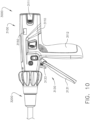
- FIGS. 10-12 depict a surgical stapling assembly 3000 comprising a handle assembly 3100 and a shaft assembly 3200.
- the surgical stapling assembly 3000 further comprises an end effector assembly and a staple cartridge assembly 3300 configured to be installed into a cartridge channel jaw of the end effector assembly.
- the handle assembly 3100 comprises a housing 3110 comprising a pistol grip portion 3112.
- the handle assembly 3100 further comprises a battery 3111 configured to power various onboard electrical components of the stapling assembly 3000, a plurality of triggers 3130 configured to actuate various functions of the surgical stapling assembly 3000, and a housing aperture, or scanning window, 3150 defined in the housing 3110.
- the triggers 3130 comprise a clamping trigger 3131 configured to clamp and unclamp tissue and a firing trigger 3133 configured to cut and staple tissue.
- a user is configured to insert the staple cartridge assembly 3330 which is about to be installed into the end effector assembly into the housing aperture 3150. Inserting the staple cartridge assembly 3300 can allow the handle assembly 3100 to scan for RFID tags, for example. In at least one instance, inserting an incorrect staple cartridge assembly into the housing aperture 3150 can lock out the incorrect staple cartridge assembly, discussed in greater detail below.
- the staple cartridge assembly 3300 is configured to be installed into and removed from a cartridge channel jaw, for example.
- the staple cartridge assembly 3300 is replaceable with other staple cartridge assemblies.
- the staple cartridge assembly 3300 comprises a cartridge body 3310, a plurality of staples 3320, a pan 3330, and a firing member, or sled, 3340 configured to be pushed through the cartridge body 3310 by a firing drive to eject the staples 3320 from the cartridge body 3310.
- the cartridge body 3310 comprises a plurality of staple cavities 3311 configured to removably store the staples 3320 therein, a longitudinal slot 3313 configured to guide the sled 3340 through the cartridge body 3310 through a firing stroke and configured to receive a cutting member of the firing drive.
- the pan 3330 is configured to hold the staples 3320 and/or staple drivers within the staple cavities 3311.
- the sled 3340 is configured to lift the staple drivers and/or staples 3320 out of the staple cavities.
- the sled 3340 comprises ramps 3343 configured to engage the staple drivers and/or staples 3320 as the sled 3340 is pushed distally through the cartridge body 3310.
- the sled 3340 comprises a central portion 3341 configured to be guided within the slot 3313.
- the sled 3340 further comprises an RFID tag 3350 embedded within the central portion 3341.
- the RFID tag 3350 is readable by a reader of the handle assembly 3100 upon insertion of the staple cartridge assembly 3330 into the housing aperture 3150.
- a proximal end of the staple cartridge assembly 3330, where the sled 3340 resides in a proximal unfired position ( FIGS. 11 and 12 ), is inserted into the housing aperture 3150 to scan the RFID tag 3350.
- the RFID tag 3350 is unreadable, or undetectable, by a reader of the handle assembly 3100. Such a configuration may prevent the need to write the spent/unspent status of the staple cartridge assembly onto the RFID tag 3350 at least because the physical position of the sled 3340 and the detectability of the RFIDrag 3350 determines if the staple cartridge assembly 3300 is spent or unspent. A staple cartridge assembly 3300 can be considered spent if the sled 3340 is not in the position illustrated in FIG. 11 and 12 .
- the RFID tag 3350 may also comprise identifiable information to determine one or more other parameters of the staple cartridge assembly 3300 such as those disclosed herein.
- FIGS. 13-15 depict a staple cartridge assembly 3400 detectable by an RFID reader, for example.
- the staple cartridge assembly 3400 may be used with a handle assembly such as, for example, the handle assembly 3100.
- the staple cartridge assembly 3400 further comprises means for voiding a non-authentic staple cartridge assembly, discussed in greater detail below.
- the staple cartridge assembly 3400 comprises a cartridge body 3410, a pan 3420, and a sled 3440.
- the cartridge body 3410 comprises a plurality of staple cavities 3411 defined in a deck surface of the cartridge body 3410 and a longitudinal slot 3414 defined in and extending between a proximal end 3401 and a distal end 3403 of the staple cartridge assembly 3400 through which the sled 3440 is configured to translate to eject staples from the cartridge body 3410.
- the sled 3440 is translatable between a proximal unfired position ( FIG 14 ) and a distal fully fired position ( FIG. 15 ).
- the sled 3440 comprises a central portion 3441 defining a top surface 3342.
- the sled 3440 further comprises an RFID tag 3450.
- the RFID tag 3450 is embedded within the top surface 3342.
- the RFID tag 3450 is positioned on the top surface 3342.
- the RFID tag 3450 is detectable by an RFID reader of a handle assembly, for example.
- the staple cartridge assembly 3400 further comprises an authentication key 3460.
- the authentication key 3460 comprises the proximal profile of the staple cartridge assembly 3400 which comprises the notched, or angled, profile of the cartridge body 3410 at the proximal end 3401 and the notched, or angled, profile of a proximal end of the sled 3440.
- the authentication key 3460 is configured to correspond to a corresponding profile of the housing aperture 3150 such that, if the profiles of the authentication key 3460 and the housing aperture 3150 do not match, the RFID tag is unreadable and/or undetectable. In at least one instance, if the profiles do not match, a feature within the housing aperture 3150 is configured to push the sled of the non-authentic staple cartridge assembly distally into a spent, or partially spent, position. Such a configuration may void non-authentic staple cartridge assemblies, for example, preventing their use with an authentic surgical stapling assembly.
- the authentication key 3460 comprises a "V" notch profile and is complemented by both the proximal end 3401 of the cartridge body 3410 in addition to the proximal end of the sled 3440.
- the "V" notch profile is matched within the housing aperture 3150 within which the staple cartridge assembly 3400 is designed to be inserted.
- RFID tags and/or chips disclosed herein comprise integrated antennas which can provide a predetermined detectability range.
- the range may comprise, for example, 10mm and/or 15mm, for example.
- the detectability range is less than 10mm, more than 10mm but less than 15mm, and/or more than 15mm.
- a light 3155 of the handle assembly 3100 illuminates upon detection of an RFID tag.
- the light 3155 is configured to flash and/or change colors to specifically convey information corresponding to the detected RFID tag. For example, the light may flash red if a non-authentic staple cartridge assembly has been inserted into the aperture window and/or if a non-authentic RFID tag has been detected.
- the light is configured to illuminate solid green if an unspent, authentic staple cartridge assembly and/or RFID tag is detected.
- the light 3155 may blink red, for example, so as to provide a warning signal to a user.
- the warning signal may indicate an issue with a firing sequence of a surgical stapling system and/or staple cartridge assembly, for example.
- the warning signal may indicate a jam within one or more drivetrain components of a surgical stapling system.
- only one of the ends 3401, 3403 is sized so as to fit within the housing aperture 3150. Such a configuration may prevent the insertion of an incorrect end of the staple cartridge assembly 3400 into the housing aperture 3150.
- a staple cartridge assembly including a staple retainer is configured to be inserted into the housing aperture 3150 while the staple retainer is attached to the staple cartridge assembly.
- FIGS. 16 and 17 depict a surgical stapling assembly 4000 comprising a handle assembly 4100, a shaft assembly 4200, and an end effector assembly 4300.
- the surgical stapling assembly 4000 further comprises a staple cartridge assembly 4400 comprising a cartridge assembly 4410 and a staple retainer 4420 removable from the cartridge assembly 4410.
- the handle assembly 4100 comprises a housing 4110 comprising a scanning aperture 4111 defined therein configured to receive only the staple retainer 4420.
- the staple retainer 4420 comprises an RFID tag, for example.
- a user may not be able to scan the RFID tag of the staple retainer 4420 while the staple retainer 4420 is still attached to the cartridge assembly 4410.
- Such a configuration may prevent a staple cartridge assembly from being scanned while the stapler retainer and the cartridge assembly are attached to each other.
- Such a configuration may help prevent scanning an RFID tag of one staple cartridge assembly, misplacing the just-scanned staple cartridge assembly prior to installation, picking up a different staple cartridge assembly and removing the staple retainer to install the different staple cartridge assembly.
- a user may follow a routine of installing the cartridge assembly 4410 into the end effector assembly 4300 and then scanning for an RFID tag by inserting the staple retainer of the just-installed cartridge assembly 4410 into the scanning aperture 4111. In at least one instance, the surgical stapling assembly 4000 is locked out until an RFID tag of the installed reload, or staple cartridge assembly, is detected.
- FIGS. 18 and 19 depict a staple cartridge assembly 4500 configured to be installed into a cartridge channel jaw 4530.
- the staple cartridge assembly 4500 comprises a cartridge assembly 4510 comprising a distal nose 4511.
- the staple cartridge assembly 4500 further comprises a staple retainer 4520 configured to be attached to and detached from the cartridge assembly 4510.
- the staple retainer 4520 comprises a primary body portion 4521 configured to cover a top portion of the cartridge assembly 4510 such as, for example, the staple cavities, longitudinal slot, and cartridge deck surface.
- the staple retainer 4520 further comprises a distal hook nose 4523 fitted around the distal nose 4511 of the cartridge assembly 4510. The staple retainer 4520 is prevented from being removed prior to installation of the staple cartridge assembly 4500 into the cartridge channel jaw 4530.
- the staple retainer 4520 further comprises a camming feature 4526.
- the camming feature 4526 fits within the longitudinal slot of the cartridge assembly 4510.
- the camming feature 4526 is configured to be pushed vertically away from the cartridge assembly 4510 upon installation of the staple cartridge assembly 4500 into the cartridge channel jaw 4530 by one or more sidewalls 4531 of the cartridge channel jaw 4530.
- the camming feature 4526 is configured to detach and/or at least partially detach the distal hook nose 4523 of the staple retainer 4520 from the primary body portion 4521 as the camming feature 4526 is pushed vertically away from the cartridge assembly 4510 to allow the staple retainer 4520 to be removed from the cartridge assembly 4510 after the staple cartridge assembly 4500 is fully installed within the cartridge channel jaw 4530.
- the staple retainer 4520 is molded with perforations designed to tear during installation of the staple cartridge assembly 4500 into the cartridge channel jaw 4530 allowing the distal hook nose 4523 to disengage from the distal nose 4511 of the cartridge assembly 4510.
- the distal hook nose 4523 is completely torn away from the body portion 4521.
- the camming feature 4526 comprises a spring feature biased downwardly into the position illustrated in FIG. 18 and the camming feature 4526 reverts back to this position after the staple retainer 4520 is slid away, or detached from, the distal nose 4511 and the cartridge assembly 4510. Nonetheless, once the staple cartridge assembly 4500 is fully installed, the staple retainer 4520 can then be removed from the cartridge assembly 4510.
- FIGS. 20-22 depict a staple cartridge assembly 4600 for use with a surgical stapling assembly such as those disclosed herein, for example.
- the staple cartridge assembly 4600 comprises a cartridge assembly 4610 and a staple retainer 4640 configured to be removed from the cartridge assembly 4610 prior to use of the cartridge assembly 4610 installed within a stapling assembly.
- the cartridge assembly 4610 comprises a cartridge body 4620 and a pan 4630.
- the cartridge body 4620 further comprises a longitudinal slot 4621 configured to receive a firing member therethrough defined by inner cartridge body walls 4622.
- the cartridge body 4620 further comprises a lower cavity channel 4623 configured to receive at least a portion of a sled, for example, therethrough.
- the staple cartridge assembly 4600 is configured to be installed in a cartridge channel 4660 comprising channel walls 4663 and a longitudinal camming slot 4661 configured to receive a camming foot of a firing member therethrough.
- the staple retainer 4640 is configured to be removed from the cartridge assembly 4610 prior to firing the cartridge assembly 4610. Once the cartridge assembly 4610 has been fired and/or is ready to be removed from the cartridge channel 4660, the staple retainer 4640 can be used to pry the cartridge assembly 4610 from the cartridge channel 4660.
- the staple retainer 4640 comprises a body portion 4641, a longitudinal rib 4643 extending from the body portion 4641 and configured to be received within the slot 4621, holding arms 4642 configured to hold the staple retainer 4640 to the cartridge assembly 4610, and a proximal portion 4650 configured to be used as a pry tool for removing the cartridge assembly 4610 from the cartridge channel 4660 and a locking feature to prevent the cartridge assembly 4610 from being used again.
- the proximal portion 4650 of the staple retainer 4640 comprises a pry cavity 4651 defined by a leverage hook 4652 and a pry tool portion 4653.
- the pry cavity 4651 is configured to be positioned around the nose of the cartridge assembly 4610 such that the hook 4652 engages a bottom surface of the nose of the cartridge assembly 4610 and the pry tool portion 4653 can be positioned within the longitudinal slot 4621.
- the proximal portion 4650 is lifted to pivot the retainer 4640 relative to the cartridge assembly 4610 so as to insert the pry tool portion fully into the slot 4621 and toward a bottom surface 4661 of the cartridge channel 4660. Once the position in FIGS. 21 and 22 is attained, leverage is gained on the cartridge assembly 4610 against the cartridge channel 4660 to pry the cartridge assembly 4610 out of the cartridge channel 4610.
- the pry tool portion 4653 further comprises locking ledges 4653 extending laterally from the pry tool portion 4653.
- the locking ledges 4653 are configured to bias the inner walls 4621 laterally outwardly so as to insert the locking ledges 4653 into the lower cavity channel 4623. Once the ledges 4653 clear the bottom of the walls 4622, the walls spring back inwardly into their home position ( FIG. 22 ). At this point, the staple retainer 4640 is locked to the cartridge assembly 4610 as the ledges 4654 prevent the staple retainer 4640 from being detached from the cartridge assembly 4610.
- Such a configuration can prevent inadvertent reuse of a cartridge assembly 4610 by permanently, in at least one instance, locking the staple retainer 4640 to the cartridge assembly 4610 in a non-functional configuration ( FIG. 21 ).
- a user would not install the staple cartridge assembly 4600 in the non-functional configuration illustrated in FIG. 21 .
- the ledges 2653 are flexible and walls 4621 are more rigid than the ledges 2653. In such an instance, the ledges 2653 deform inwardly as the ledges 2653 move vertically through the slot 4621 and spring back to their undeformed position ( FIG. 22 ) upon reaching the lower cavity channel 4623.
- the staple retainer 4640 is required to remove the cartridge assembly 4610 from the cartridge channel 4660.
- locking the staple retainer 4640 to the cartridge channel 4660 also prevents an attempt to reuse the staple retainer 4640 with a non-authentic staple cartridge assembly, for example.
- the pry tool may also reduce the force required to remove the cartridge assembly 4610 from the cartridge channel 4660.
- FIGS. 23-26 depict a surgical stapling assembly 5000.
- the surgical stapling assembly 5000 comprises a handle assembly 5100, a shaft assembly 5200, and an end effector assembly 5300 configured to receive a replaceable staple cartridge assembly therein.
- the handle assembly 5100 comprises a handle housing 5110 comprising an aperture 5111 defined therein. Discussed in greater detail below, a user is configured to insert a staple retainer 5430 of the staple cartridge assembly into the aperture 5111 in order to detect the type of staple cartridge assembly that is installed in the end effector assembly 5300.
- the end effector assembly 5300 comprises an anvil jaw 5320 and a cartridge channel jaw 5310 configured to receive the staple cartridge assembly therein.
- the staple cartridge assembly comprises a cartridge assembly 5410 and a cartridge retainer 5430.
- the cartridge retainer 5430 is configured to be removed from the cartridge assembly 5410 after the staple cartridge assembly is installed within the cartridge channel jaw 5310.
- the staple retainer 5430 comprises a proximal end and a distal end 5433.
- the proximal end 5431 of the staple retainer 5430 further comprises a unique profile 5440 of features 5441, 5443.
- the features 5441, 5443 comprise proximally-extending tabs 5441 and one or more gaps 5443 between the tabs 5441.
- the features 5441, 5443 are unique to each type of staple cartridge assembly.
- the profile of features 5441, 5443 are specific so as to be able to identify the type of staple cartridge assembly to which the staple retainer 5430 is attached.
- the proximal end 5431 is configured to be inserted into the aperture 5111 of the housing 5100 to engage a detection system 5130.
- the detection system 5130 comprises a plurality of sensors 5133 such as switches, for example, which are coupled to a printed circuit board 5131 and a control circuit.
- the specific combination of switches which are detected to be switched on, for example, can indicate one or more identifiable parameters of the staple cartridge assembly.
- a different staple retainer 5530 having different identifiable parameters comprises a different unique profile 5540 of features 5541, 5543 configured to press a different combination of the switches 5133, for example.
- the features 5541, 5543 comprise proximally-extending tabs 5541 and one or more gaps 5543 between the tabs 5541.
- the different unique profile 5540 is configured to indicate different identifiable parameters of a different staple cartridge assembly to which the staple retainer 5530 is attached to a control circuit of the surgical stapling system 5500.
- an end effector in accordance with various embodiments can comprise electrodes configured to heat and seal the tissue.
- an end effector in accordance with certain embodiments can apply vibrational energy to seal the tissue.
- a machine-readable medium may include any mechanism for storing or transmitting information in a form readable by a machine (e.g., a computer), but is not limited to, floppy diskettes, optical disks, compact disc, read-only memory (CD-ROMs), and magneto-optical disks, read-only memory (ROMs), random access memory (RAM), erasable programmable read-only memory (EPROM), electrically erasable programmable read-only memory (EEPROM), magnetic or optical cards, flash memory, or a tangible, machine-readable storage used in the transmission of information over the Internet via electrical, optical, acoustical or other forms of propagated signals (e.g., carrier waves, infrared signals, digital signals, etc.). Accordingly, the non-
- control circuit may refer to, for example, hardwired circuitry, programmable circuitry (e.g., a computer processor including one or more individual instruction processing cores, processing unit, processor, microcontroller, microcontroller unit, controller, digital signal processor (DSP), programmable logic device (PLD), programmable logic array (PLA), or field programmable gate array (FPGA)), state machine circuitry, firmware that stores instructions executed by programmable circuitry, and any combination thereof.
- programmable circuitry e.g., a computer processor including one or more individual instruction processing cores, processing unit, processor, microcontroller, microcontroller unit, controller, digital signal processor (DSP), programmable logic device (PLD), programmable logic array (PLA), or field programmable gate array (FPGA)
- state machine circuitry firmware that stores instructions executed by programmable circuitry, and any combination thereof.
- the control circuit may, collectively or individually, be embodied as circuitry that forms part of a larger system, for example, an integrated circuit (IC), an application-specific integrated circuit (ASIC), a system on-chip (SoC), desktop computers, laptop computers, tablet computers, servers, smart phones, etc.
- IC integrated circuit
- ASIC application-specific integrated circuit
- SoC system on-chip
- control circuit includes, but is not limited to, electrical circuitry having at least one discrete electrical circuit, electrical circuitry having at least one integrated circuit, electrical circuitry having at least one application specific integrated circuit, electrical circuitry forming a general purpose computing device configured by a computer program (e.g., a general purpose computer configured by a computer program which at least partially carries out processes and/or devices described herein, or a microprocessor configured by a computer program which at least partially carries out processes and/or devices described herein), electrical circuitry forming a memory device (e.g., forms of random access memory), and/or electrical circuitry forming a communications device (e.g., a modem, communications switch, or optical-electrical equipment).
- a computer program e.g., a general purpose computer configured by a computer program which at least partially carries out processes and/or devices described herein, or a microprocessor configured by a computer program which at least partially carries out processes and/or devices described herein
- electrical circuitry forming a memory device
- logic may refer to an app, software, firmware and/or circuitry configured to perform any of the aforementioned operations.
- Software may be embodied as a software package, code, instructions, instruction sets and/or data recorded on non-transitory computer readable storage medium.
- Firmware may be embodied as code, instructions or instruction sets and/or data that are hard-coded (e.g., nonvolatile) in memory devices.
- the terms "component,” “system,” “module” and the like can refer to a computer-related entity, either hardware, a combination of hardware and software, software, or software in execution.
- an “algorithm” refers to a self-consistent sequence of steps leading to a desired result, where a “step” refers to a manipulation of physical quantities and/or logic states which may, though need not necessarily, take the form of electrical or magnetic signals capable of being stored, transferred, combined, compared, and otherwise manipulated. It is common usage to refer to these signals as bits, values, elements, symbols, characters, terms, numbers, or the like. These and similar terms may be associated with the appropriate physical quantities and are merely convenient labels applied to these quantities and/or states.
- a network may include a packet switched network.
- the communication devices may be capable of communicating with each other using a selected packet switched network communications protocol.
- One example communications protocol may include an Ethernet communications protocol which may be capable permitting communication using a Transmission Control Protocol/Internet Protocol (TCP/IP).
- TCP/IP Transmission Control Protocol/Internet Protocol
- the Ethernet protocol may comply or be compatible with the Ethernet standard published by the Institute of Electrical and Electronics Engineers (IEEE) titled "IEEE 802.3 Standard", published in December, 2008 and/or later versions of this standard.
- the communication devices may be capable of communicating with each other using an X.25 communications protocol.
- the X.25 communications protocol may comply or be compatible with a standard promulgated by the International Telecommunication Union-Telecommunication Standardization Sector (ITU-T).
- the communication devices may be capable of communicating with each other using a frame relay communications protocol.
- the frame relay communications protocol may comply or be compatible with a standard promulgated by Consultative Committee for International Circuit and Telephone (CCITT) and/or the American National Standards Institute (ANSI).
- the transceivers may be capable of communicating with each other using an Asynchronous Transfer Mode (ATM) communications protocol.
- ATM Asynchronous Transfer Mode
- the ATM communications protocol may comply or be compatible with an ATM standard published by the ATM Forum titled "ATM-MPLS Network Interworking 2.0" published August 2001, and/or later versions of this standard.
- ATM-MPLS Network Interworking 2.0 published August 2001
- One or more components may be referred to herein as “configured to,” “configurable to,” “operable/operative to,” “adapted/adaptable,” “able to,” “conformable/conformed to,” etc.
- “configured to” can generally encompass active-state components and/or inactive-state components and/or standby-state components, unless context requires otherwise.
- proximal and distal are used herein with reference to a clinician manipulating the handle portion of the surgical instrument.
- proximal refers to the portion closest to the clinician and the term “distal” refers to the portion located away from the clinician.
- distal refers to the portion located away from the clinician.
- spatial terms such as “vertical”, “horizontal”, “up”, and “down” may be used herein with respect to the drawings.
- surgical instruments are used in many orientations and positions, and these terms are not intended to be limiting and/or absolute.
- any reference to “one aspect,” “an aspect,” “an exemplification,” “one exemplification,” and the like means that a particular feature, structure, or characteristic described in connection with the aspect is included in at least one aspect.
- appearances of the phrases “in one aspect,” “in an aspect,” “in an exemplification,” and “in one exemplification” in various places throughout the specification are not necessarily all referring to the same aspect.
- the particular features, structures or characteristics may be combined in any suitable manner in one or more aspects.
Abstract
A surgical stapling system comprising an instrument interface comprising a control circuit and an RFID reader is disclosed. The surgical stapling system further comprises a shaft assembly comprising a shaft and an end effector. The end effector comprises a first jaw, a second jaw, an anvil, and a cartridge channel. The surgical stapling system further comprises a replaceable staple cartridge assembly removably positioned within the cartridge channel. The replaceable staple cartridge assembly comprises a cartridge body, a longitudinal slot, a plurality of staple cavities, a plurality of staples, and a staple cartridge retainer. The staple cartridge retainer comprises a rib, a body portion, and an RFID tag embedded within the body portion, wherein the RFID tag comprises a memory, wherein the memory comprises identifier information stored in the memory specific to the staple cartridge, and wherein the identifier information is accessible by the RFID reader.
Description
- The present disclosure relates to surgical instruments, including surgical staplers configured to staple and cut tissue, which are usable as handheld instruments and/or as surgical tools connectable to surgical robots.
- The various aspects described herein, both as to organization and methods of operation, together with further objects and advantages thereof, may best be understood by reference to the following description, taken in conjunction with the accompanying drawings as follows.
-
FIG. 1 is a perspective view of a surgical stapling instrument comprising a handle, a shaft assembly, and an end effector assembly; -
FIG. 2 is a perspective view of the end effector assembly ofFIG. 1 ; -
FIG. 3 is a perspective view of the end effector assembly ofFIG. 1 , wherein the end effector assembly comprises a staple cartridge assembly, and wherein the staple cartridge assembly comprises a retainer, and wherein the staple cartridge assembly is illustrated removed from a cartridge channel of the end effector assembly; -
FIG. 4 is perspective view of a portion of the shaft assembly and the handle ofFIG. 1 ; -
FIG. 5 is schematic view of the surgical stapling instrument ofFIG. 1 ; -
FIG. 6 is an elevational view of a surgical stapling assembly comprising a surgical instrument handle, a shaft assembly, an end effector assembly, and a staple cartridge assembly comprising a staple retainer and a cartridge assembly, wherein the staple retainer is detectable by the surgical instrument handle; -
FIG. 7 is a perspective view of the staple cartridge assembly ofFIG. 6 , wherein the staple retainer comprises an RFID tag embedded therein; -
FIG. 8 is an elevational view of the surgical stapling assembly ofFIG. 6 , wherein the staple retainer is positioned near the surgical instrument handle for detection of the RFID tag; -
FIG. 9 is a plan view of a surgical instrument identification system comprising a housing and a staple retainer, wherein the staple retainer comprises an RFID tag, wherein the staple retainer is inserted into an aperture defined in the housing for detecting the RFID tag; -
FIG. 10 is an elevational view of a surgical instrument interface comprising an instrument handle, wherein the instrument handle comprises a handle housing, and wherein the handle housing comprises an aperture defined therein for receiving one or more portions of a staple cartridge assembly; -
FIG. 11 is a perspective view of a staple cartridge assembly comprising a cartridge body, a cartridge pan, and a sled comprising an RFID tag; -
FIG. 12 is a partially cross-sectional view of the staple cartridge assembly ofFIG. 11 ; -
FIG. 13 is a plan view of a staple cartridge assembly comprising a cartridge body, a cartridge pan, and a sled comprising an RFID tag; -
FIG. 14 is a plan view of the staple cartridge assembly ofFIG. 13 , wherein the sled is illustrated in an unfired position; -
FIG. 15 is a plan view of the staple cartridge assembly ofFIG. 13 , wherein the sled is illustrated in a fired position; -
FIG. 16 is an elevational view of a surgical stapling assembly comprising an instrument handle, a shaft assembly, an end effector assembly, and a staple cartridge assembly comprising a staple retainer and a cartridge assembly; -
FIG. 17 is an elevational view of the surgical stapling assembly ofFIG. 16 , wherein the staple cartridge assembly is illustrated in a non-readable configuration; -
FIG. 18 is a partial elevational view of a staple cartridge assembly comprising a staple retainer and a cartridge assembly, wherein the staple retainer comprises a locking feature configured to prevent removal of the staple retainer prior to installation of the staple cartridge assembly into a cartridge channel of a surgical instrument, wherein the locking feature is illustrated in a locked configuration; -
FIG. 19 is a partial elevational view of the staple cartridge assembly ofFIG. 18 installed in a cartridge channel, wherein the locking feature is illustrated in an unlocked configuration; -
FIG. 20 is an elevational view of a staple cartridge assembly comprising a cartridge assembly and a staple retainer, wherein the staple retainer comprises a pry feature and a locking feature configured to lock the staple retainer to the cartridge assembly upon using the pry feature to remove the cartridge assembly from a cartridge channel; -
FIG. 21 is an elevational view of the staple cartridge assembly ofFIG. 20 installed in a cartridge channel, wherein the locking feature is illustrated in a locked configuration; -
FIG. 22 is a cross-sectional view of the staple cartridge assembly ofFIG. 20 installed within the cartridge channel, wherein the locking feature is illustrated in the locked configuration; -
FIG. 23 is an elevational view of a surgical stapling assembly comprising an instrument interface and a staple cartridge assembly, wherein the staple cartridge assembly comprises a staple retainer comprising a pattern of features configured to be detected by the instrument interface and indicative of information specific to the staple cartridge assembly; -
FIG. 24 is a plan view of the staple retainer ofFIG. 23 ; -
FIG. 25 is a partial elevational view of the staple retainer and the instrument interface ofFIG. 23 ; and -
FIG. 26 is a partial elevational view of a staple retainer different than the staple retainer ofFIG. 23 and the instrument interface ofFIG. 23 . - Corresponding reference characters indicate corresponding parts throughout the several views. The exemplifications set out herein illustrate various embodiments of the invention, in one form, and such exemplifications are not to be construed as limiting the scope of the invention in any manner.
- Numerous specific details are set forth to provide a thorough understanding of the overall structure, function, manufacture, and use of the embodiments as described in the specification and illustrated in the accompanying drawings. Well-known operations, components, and elements have not been described in detail so as not to obscure the embodiments described in the specification. The reader will understand that the embodiments described and illustrated herein are non-limiting examples, and thus it can be appreciated that the specific structural and functional details disclosed herein may be representative and illustrative. Variations and changes thereto may be made without departing from the scope of the claims.
- The terms "comprise" (and any form of comprise, such as "comprises" and "comprising"), "have" (and any form of have, such as "has" and "having"), "include" (and any form of include, such as "includes" and "including") and "contain" (and any form of contain, such as "contains" and "containing") are open-ended linking verbs. As a result, a surgical system, device, or apparatus that "comprises," "has," "includes" or "contains" one or more elements possesses those one or more elements, but is not limited to possessing only those one or more elements. Likewise, an element of a system, device, or apparatus that "comprises," "has," "includes" or "contains" one or more features possesses those one or more features, but is not limited to possessing only those one or more features.
- The terms "proximal" and "distal" are used herein with reference to a clinician manipulating the handle portion of the surgical instrument. The term "proximal" refers to the portion closest to the clinician and the term "distal" refers to the portion located away from the clinician. It will be further appreciated that, for convenience and clarity, spatial terms such as "vertical", "horizontal", "up", and "down" may be used herein with respect to the drawings. However, surgical instruments are used in many orientations and positions, and these terms are not intended to be limiting and/or absolute.
- Various exemplary devices and methods are provided for performing laparoscopic and minimally invasive surgical procedures. However, the reader will readily appreciate that the various methods and devices disclosed herein can be used in numerous surgical procedures and applications including, for example, in connection with open surgical procedures. As the present Detailed Description proceeds, the reader will further appreciate that the various instruments disclosed herein can be inserted into a body in any way, such as through a natural orifice, through an incision or puncture hole formed in tissue, etc. The working portions or end effector portions of the instruments can be inserted directly into a patient's body or can be inserted through an access device that has a working channel through which the end effector and elongate shaft of a surgical instrument can be advanced.
- A surgical stapling system can comprise a shaft and an end effector extending from the shaft. The end effector comprises a first jaw and a second jaw. The first jaw comprises a staple cartridge. The staple cartridge is insertable into and removable from the first jaw; however, other embodiments are envisioned in which a staple cartridge is not removable from, or at least readily replaceable from, the first jaw. The second jaw comprises an anvil configured to deform staples ejected from the staple cartridge. The second jaw is pivotable relative to the first jaw about a closure axis; however, other embodiments are envisioned in which the first jaw is pivotable relative to the second jaw. The surgical stapling system further comprises an articulation joint configured to permit the end effector to be rotated, or articulated, relative to the shaft. The end effector is rotatable about an articulation axis extending through the articulation joint. Other embodiments are envisioned which do not include an articulation joint.
- The staple cartridge comprises a cartridge body. The cartridge body includes a proximal end, a distal end, and a deck extending between the proximal end and the distal end. In use, the staple cartridge is positioned on a first side of the tissue to be stapled and the anvil is positioned on a second side of the tissue. The anvil is moved toward the staple cartridge to compress and clamp the tissue against the deck. Thereafter, staples removably stored in the cartridge body can be deployed into the tissue. The cartridge body includes staple cavities defined therein wherein staples are removably stored in the staple cavities. The staple cavities are arranged in six longitudinal rows. Three rows of staple cavities are positioned on a first side of a longitudinal slot and three rows of staple cavities are positioned on a second side of the longitudinal slot. Other arrangements of staple cavities and staples may be possible.
- The staples are supported by staple drivers in the cartridge body. The drivers are movable between a first, or unfired position, and a second, or fired, position to eject the staples from the staple cavities. The drivers are retained in the cartridge body by a retainer which extends around the bottom of the cartridge body and includes resilient members configured to grip the cartridge body and hold the retainer to the cartridge body. The drivers are movable between their unfired positions and their fired positions by a sled. The sled is movable between a proximal position adjacent the proximal end and a distal position adjacent the distal end. The sled comprises a plurality of ramped surfaces configured to slide under the drivers and lift the drivers, and the staples supported thereon, toward the anvil.
- Further to the above, the sled is moved distally by a firing member. The firing member is configured to contact the sled and push the sled toward the distal end. The longitudinal slot defined in the cartridge body is configured to receive the firing member. The anvil also includes a slot configured to receive the firing member. The firing member further comprises a first cam which engages the first jaw and a second cam which engages the second jaw. As the firing member is advanced distally, the first cam and the second cam can control the distance, or tissue gap, between the deck of the staple cartridge and the anvil. The firing member also comprises a knife configured to incise the tissue captured intermediate the staple cartridge and the anvil. It is desirable for the knife to be positioned at least partially proximal to the ramped surfaces such that the staples are ejected ahead of the knife.
- Before explaining various aspects of surgical devices and generators in detail, it should be noted that the illustrative examples are not limited in application or use to the details of construction and arrangement of parts illustrated in the accompanying drawings and description. The illustrative examples may be implemented or incorporated in other aspects, variations and modifications, and may be practiced or carried out in various ways. Further, unless otherwise indicated, the terms and expressions employed herein have been chosen for the purpose of describing the illustrative examples for the convenience of the reader and are not for the purpose of limitation thereof. Also, it will be appreciated that one or more of the following-described aspects, expressions of aspects, and/or examples, can be combined with any one or more of the other following-described aspects, expressions of aspects and/or examples.
- Certain exemplary embodiments will now be described to provide an overall understanding of the principles of the structure, function, manufacture, and use of the devices and methods disclosed herein. One or more examples of these exemplary embodiments are illustrated in the accompanying drawings. Those of ordinary skill in the art will understand that the devices and methods specifically described herein and illustrated in the accompanying drawings are non-limiting exemplary embodiments and that the scope of the various exemplary embodiments of the present invention is defined solely by the claims. The features illustrated or described in connection with one exemplary embodiment may be combined with the features of other exemplary embodiments. Such modifications and variations are intended to be included within the scope of the present invention.
-
FIGS. 1-5 depict asurgical stapling instrument 1000 configured to cut and staple tissue of a patient. Thesurgical stapling instrument 1000 comprises a housing, or handle,assembly 1100, ashaft assembly 1200 attached to thehandle assembly 1100, and anend effector assembly 1300. Thehandle assembly 1100 comprises ahousing 1101 configured to house various components therein such as, for example, electronics, motors, and/or drive train components. Thehandle assembly 1100 comprises apistol grip portion 1120 comprising ahandle 1121 configured to be held by a user, aclosure trigger 1125 configured to clamp tissue with theend effector assembly 1300, and a firing trigger, or button, 1129 configured to cut and staple tissue with theend effector assembly 1300. Thehandle assembly 1100 further comprises a plurality of actuators and/orbuttons 1130 configured to electronically actuate various functions of thesurgical stapling instrument 1000. In at least one instance, theactuators 1130 are configured to actuate motorized articulation of theend effector assembly 1300 and/or rotation of theshaft assembly 1200 and/or endeffector assembly 1300. - In at least one instance, the
handle assembly 1100 comprises a plurality of motors positioned therein configured to drive one or more functions of thesurgical stapling instrument 1000. Thehandle assembly 1100 further comprises one or more power sources such as, for example,batteries 1110 configured to power onboard electronics such as, for example, the printedcircuit boards handle assembly 1100. In at least one instance, thehandle assembly 1100 comprises one or more onboard memories, processors, and/or control circuits configured to analyze sensor data and/or control various electronic systems of the surgical stapling instrument such as, for example, motor control programs. Thehandle assembly 1100 may be in wireless communication with a surgical hub and/or various other components of a surgical operating suite to communicate various data between thehandle assembly 1100 and the surgical hub, for example. - The
shaft assembly 1200 is attached to thehandle assembly 1100. In at least one instance, theshaft assembly 1200 is modular and can be replaced with another shaft assembly of another surgical instrument attachment, for example. In at least one instance, theshaft assembly 1200 comprises one or more of the printedcircuit boards shaft assembly 1200 is configured to house a plurality of components of thesurgical stapling instrument 1000 such as, for example, drive shafts, electronics, sensors, wires, and/or frame components, for example. Such components are configured to be coupled to corresponding components positioned within thehandle assembly 1100 such as, for example, motors, supply leads, wires, and/or drive train components, for example. Theshaft assembly 1200 houses such components and transfers such components to theend effector assembly 1300 to drive various functions of theshaft assembly 1200 and/or endeffector assembly 1300 and/or transfer electrical signals between theshaft assembly 1200 and theend effector assembly 1300 and to/from thehandle assembly 1100, for example. Theshaft assembly 1200 compriseselectrical leads 1160 electrically coupled with one or more of the printedcircuit boards shaft assembly 1200 and/or theend effector assembly 1300. - The
shaft assembly 1200 comprises aproximal attachment portion 1220, a primaryouter shaft 1210, and an articulation joint 1230. Theend effector assembly 1300 is articulatable relative to theshaft 1210 by way of the articulation joint 1230. Theend effector assembly 1300 is articulatable about the articulation axis AA (FIG. 1 ). In at least one instance, theend effector assembly 1300 andshaft assembly 1200 are configured to be inserted through a trocar penetrating into a patient's body cavity to clamp, staple, and cut tissue of a patient. In at least one instance, theproximal attachment portion 1220 comprises one or more contacts configured to transmit electrical signals, power and/or data, for example, between theend effector assembly 1300, theshaft assembly 1200, and thehandle assembly 1100. In at least one instance, the contacts comprises conductor rings configured to permit rotation of theshaft assembly 1200 relative to thehandle assembly 1100 about a central longitudinal axis while still permitting electrical transmission between theshaft assembly 1200 and thehandle assembly 1100. - The
end effector assembly 1300 comprises afirst jaw 1310 and asecond jaw 1340 movable relative to thefirst jaw 1310 to grasp and ungrasp tissue therebetween. Thefirst jaw 1310 is fixed relative to thesecond jaw 1340. In at least one instance, thefirst jaw 1310 is not fixed and bothjaws first jaw 1310 comprises acartridge channel 1320 configured to receive a replaceablestaple cartridge assembly 1330 therein. Thesecond jaw 1340 comprises ananvil 1350 configured to clamp onto tissue upon actuation of theclosure trigger 1125 and form staples removably stored within the replaceablestaple cartridge assembly 1330 upon actuation of thefiring trigger 1129. Theend effector assembly 1300 further comprises a firing member assembly configured to be actuated through a firing stroke to deploy staples from the replaceablestaple cartridge assembly 1330 and cut tissue clamped between thejaws - As discussed above, the
surgical stapling instrument 1000 may comprise various electronics. Such electronics may be wireless, wired, passively powered, and/or actively powered, for example. Such electronics may be positioned within thestaple cartridge assembly 1330, on one or more components of theend effector assembly 1300 such as thecartridge channel jaw 1310 and/or theanvil jaw 1340, within theshaft assembly 1200, and/or within thehandle assembly 1100. In at least one instance, electrical leads may be required to traverse the articulation joint 1230. Various arrangements disclosed herein illustrate various ways of passing electrical leads through the articulation joint 1230. - The
staple cartridge assembly 1330 further comprises aretainer 1400 installed on thecartridge assembly 1330. In at least one instance, theretainer 1400 is configured to maintain staples within thecartridge assembly 1330 during shipping and/or installation of thecartridge assembly 1330 into thecartridge channel 1320. Theretainer 1400 is configured to be removed prior to use of thesurgical stapling instrument 1000 and thecartridge assembly 1330. - In various instances, surgical stapling systems comprise reloadable staple cartridge assemblies. Staple cartridge assemblies may be replaced during one or more surgical procedures. For example, a user may replace a used staple cartridge assembly with a new staple cartridge assembly comprising the same configuration as the used staple cartridge assembly. In at least one instance, the user may replace the used staple cartridge assembly with a new staple cartridge assembly comprising a different configuration as the used staple cartridge assembly. In at least one instance, the replaceable components include also a shaft assembly in addition to the staple cartridge assembly. At any rate, detecting the type of staple cartridge assembly to be used with the surgical stapling assembly can make a user and/or a control program, for example, aware of the type of staple cartridge assembly. Such information can be utilized in several ways.
- In at least one instance, information specific to each staple cartridge assembly can be communicated to a control program wirelessly. In at least one instance, RFID tags and RFID readers are employed (radio frequency identification). In at least one instance, NFC (near field communication) technology is employed. In at least one instance, a staple retainer, a device configured to be attached to a staple cartridge assembly during manufacturing configured to prevent staples from falling out of the staple cartridge assembly and/or protect the staple cartridge assembly during shipping, for example, comprises an embedded wireless tag such as, for example, an RFID tag. Embodiments disclosed herein can employ any suitable wireless identification technology including but not limited to RFID technology and NFC technology.
- In at least one instance, an instrument interface comprising a surgical instrument handle and/or robotic instrument interface, for example, comprises a reader device such as, for example, an RFID reader to detect an RFID tag embedded within a staple retainer.
- In at least one instance, the RFID tag comprises a passive tag. In at least one instance the RFID tag comprises an active tag. In at least one instance, the RFID tag comprises a semi passive tag. In at least one instance, the RFID tag comprises only a readable tag. In at least one instance, the RFID tag comprises a writable storage medium. In at least one instance, the frequency of operation of the RFID systems disclosed herein comprise a low frequency range, a high frequency ranges, and/or a ultrahigh frequency range. In at least one instance, the RFID technology employed herein utilizes inductive coupling and/or near field coupling. In at least one instance, the RFID technology employed herein utilizes electromagnetic coupling and/or far field coupling. In at least one instance, the RFID technology employed herein comprises an RFID chip, a processor, a memory, a transmitter, a tag antenna, a reader antenna, a modulator, a rectifier, and/or a logic circuit, for example.
- Detecting the type of staple cartridge assembly to be used with a surgical stapling system can be used to notify and/or alert a user and/or a control program of the type of staple cartridge assembly installed within an end effector, for example. The information may be made aware to a user by way of a display, for example, onboard a surgical instrument handle. The information may be automatically fed to a control program, or control circuit, of the surgical stapling system. In at least one instance, detecting the type of staple cartridge assembly to be used with a surgical stapling system can be used to alter a motor control program to specifically accommodate the type of staple cartridge assembly installed within the end effector. Firing speed, for example, can be altered based on cartridge color, length, and/or staple size.
- Such information can be communicated to a surgical hub, for example. In at least one instance, the surgical hub is configured to suggest and/or automatically employ an operational adjustment to a control program of a surgical stapling system for a specific staple cartridge assembly. In at least one instance, a surgical hub is configured to alert a user if the correct staple cartridge assembly has been installed according to known patient and/or procedural data. For example, a surgical hub may already be aware of the specific patient being operated on and, in at least one instance, the surgical hub compares the type of staple cartridge assembly installed within the surgical stapling system against data known about the specific patient. Such a configuration can be utilized to detect if an incorrect staple cartridge assembly has been installed in an end effector, for example. At such a point, the surgical hub and/or a control program of the surgical stapling instrument can lock out the instrument until the correct staple cartridge assembly is installed within the end effector.
- In at least one instance, a control program of the surgical stapling system monitors the force required to fire staples and cut tissue during a firing stroke. In such an instance, identifying the type of staple cartridge assembly being used can compare force to an expected feedback force profile, for example, specific to the staple cartridge assembly installed within the end effector. In at least one instance, taller staples may require greater force to be fired, for example. In such an instance, providing this information to a control program can allow the control program to increase the provided firing force during a firing stroke according to what force profile is expected.
- In at least one instance, information specific to the staple cartridge assembly installed within the surgical stapling instrument can comprise a batch number and/or manufacturing information such as manufacturing date, for example, specific to the staple cartridge assembly. In at least one instance, information specific to the staple cartridge assembly can comprise writable information comprising, for example, the spent/unspent status of the staple cartridge assembly, for example. In such an instance, a control program is configured to write information onto an RFID tag of a staple retainer, for example, which indicates that the staple cartridge assembly has been spent. In such an instance, should a staple retainer comprising the RFID tag be reinstalled into a staple cartridge assembly making the staple cartridge assembly appear as though it is a new, unused staple cartridge assembly, a subsequent scan of the staple retainer would inform the control circuit and/or user that the staple cartridge assembly has, in fact, been used. Such a configuration can prevent the use of an already used staple cartridge assembly.
- Surgical stapling systems utilizing RFID tags and/or readers such as those disclosed herein can reduce and/or eliminate the need for electrical leads passing through shaft assemblies, end effector assemblies, and/or articulation joints, for example to identify the type of staple cartridge assembly installed within an end effector assembly. Such staple cartridge assemblies may also be backwards compatible with a variety of different instruments as long as the instruments comprise RFID readers, for example, and the control circuits required for reading and interpreting the information gathered from the RFID tag.
-
FIGS. 6-8 depicts asurgical stapling assembly 2000 comprising a surgical instrument handle, or interface, 2100, ashaft assembly 2200 attachable to and detachable from thehandle 2100, and anend effector assembly 2300. In at least one instance, theshaft assembly 2100 is attachable to and detachable from a surgical robotic interface, in lieu of or in addition to being attachable to and detachable from thesurgical instrument handle 2100. The surgical stapling assembly 200 is configured to receive replaceable staple cartridge assembly reloads. Thesurgical stapling assembly 2000 comprises a staple cartridge assembly 2400 (FIG. 7 ) configured to be attached to theend effector assembly 2300. Thestaple cartridge assembly 2400 comprises acartridge assembly 2410 and astaple retainer 2450 configured to be detached from thecartridge assembly 2410 after thestaple cartridge assembly 2400 is installed within theend effector assembly 2300, discussed in greater detail below. - The
handle 2100 comprises ahousing 2110 configured to house a plurality of components therein such as, for example, electronics, printed circuit boards, and/or drive train components. Thehandle 2100 further comprises abattery 2111 configured to be attached to thehousing 2110 to power various onboard electronics and/or motors of thehandle 2100. Thehandle 2100 further comprises apistol grip portion 2120 configured to be held by a user and a plurality oftriggers 2130 configured to actuate various functions of thesurgical stapling assembly 2000. Thetriggers 2130 may be mechanical and/or electromechanical. Thetriggers 2130 comprise aclamping trigger 2131 configured to clamp and unclamp tissue with theend effector assembly 2300 and afiring trigger 2135 configured to cut and staple tissue clamped with theend effector assembly 2300. Thetriggers 2130 further comprise anarticulation rocker switch 2133 configured to articulate theend effector assembly 2300 about an articulation joint 2230 of theshaft assembly 2100. Discussed in greater detail below, thehandle 2100 further comprises awireless reader 2500 configured to identify thestaple cartridge assembly 2400 installed within theend effector assembly 2300. - The
shaft assembly 2200 is attachable to and detachable from thehandle 2100. Theshaft assembly 2200 houses drive shaft components, gear trains, electrical leads, sensors, and/or frame components, for example. Theshaft assembly 2200 comprises a proximalnozzle attachment interface 2210, ashaft 2220 extending distally from theinterface 2210, and the articulation joint 2230. Theend effector assembly 2300 is articulatable relative to and attached to theshaft 2220 by way of the articulation joint 2230. - The
end effector assembly 2300 is configured to clamp and unclamp tissue, cut tissue, and/or staple tissue. Theend effector assembly 2300 comprises acartridge channel jaw 2310 configured to receive thestaple cartridge assembly 2400 and ananvil jaw 2340 configured to form staples ejected from thestaple cartridge assembly 2400. Theanvil jaw 2340 is pivotable relative to thecartridge channel jaw 2310. In at least one instance, thecartridge channel jaw 2310 is pivotable relative to theanvil jaw 2340. In at least one instance, thecartridge channel jaw 2310 and theanvil jaw 2340 are pivotable relative to one another. - As discussed herein, the
staple cartridge assembly 2400 comprises acartridge assembly 2410 and astaple retainer 2450. Thecartridge assembly 2410 comprises acartridge body 2430 and apan 2420 configured to prevent drivers and/or staples from falling out of the bottom of thecartridge body 2430. Thepan 2420 is also configured to be fitted within thecartridge channel jaw 2310 upon installation of thestaple cartridge assembly 2400 in theend effector assembly 2300. In at least one instance, thestaple retainer 2450 is attached to thecartridge assembly 2410 during manufacturing. Thestaple retainer 2450 is configured to protect thecartridge assembly 2410 during shipping and/or packaging and during installation of thestaple cartridge assembly 2400 into theend effector assembly 2300, for example. After thestaple cartridge assembly 2400 is installed into theend effector assembly 2300, thestaple retainer 2450 is removed by a user. - The
staple retainer 2450 comprises abody portion 2451 positioned adjacent to a deck of thecartridge body 2430. Thebody portion 2451 comprises identifyingindicia 2452 configured to indicate one or more parameters of thestaple cartridge assembly 2400. For example, theindicia 2452 may indicate an operable length of thestaple cartridge assembly 2400. Thestaple retainer 2450 further comprises aproximal end 2456 and adistal end 2455. Thestaple retainer 2450 further comprisesprimary arms 2453 configured to hold thestaple retainer 2450 to thecartridge assembly 2410 anddistal nose arms 2454 also configured to hold thestaple retainer 2450 to thecartridge assembly 2410. Thearms cartridge assembly 2410. Thestaple retainer 2450 further comprises a slot rib 2457 (FIG. 8 ) configured to fit within a longitudinal slot of thecartridge body 2430. In at least one instance, theslot rib 2457 further holds thestaple retainer 2450 to thecartridge body 2430 by way of a snap fit and/or press fit engagement, for example. - The
distal end 2455 comprises anose portion 2457 configured to be lifted by a user to pry thestaple retainer 2450 and disengage thearms slot rib 2457 from thecartridge assembly 2410 so that thestaple retainer 2450 can be removed from thecartridge assembly 2410 prior to firing thecartridge assembly 2410. Discussed in greater detail below, thestaple retainer 2450 comprises awireless identification tag 2460 such as, for example, an RFID tag, configured to be detected by thewireless reader 2500 of thehandle 2100. - To clamp tissue between the
jaws trigger 2131 is depressed by a user. To unclamp tissue clamped between thejaws trigger 2131 and, in at least one instance, thetrigger 2131 is spring loaded such that thetrigger 2131 is biased toward an unclamped, released position (FIG. 6 ). After tissue has been clamped between thejaws firing trigger 2135 to cut the tissue and eject staples from thestaple cartridge assembly 2400. - The
surgical stapling assembly 2000 allows a user to detect the type ofstaple cartridge assembly 2400 installed within theend effector assembly 2300. Before and/or after thestaple cartridge assembly 2400 is installed within theend effector assembly 2300, theRFID tag 2460 is scanned by thewireless reader 2500. In at least one instance, thewireless reader 2500 comprises an RFID reader. In at least one instance, before and/or after thestaple cartridge assembly 2400 is installed within theend effector assembly 2300 theRFID tag 2460, thestaple retainer 2450 is brought into a detectable proximity range within theRFID reader 2500 of thehandle 2100. At such point, thereader 2500 is configured to detect theRFID tag 2460. A control circuit may be configured to take several actions after theRFID tag 2460 is read such as those described herein. For example, a display may indicate that the correct and/or incorrectstaple cartridge assembly 2400 for that specific operation has been installed within theend effector assembly 2300. In at least one instance, a control circuit makes a user and/or robotic control program aware of the type of staple cartridge installed within theend effector assembly 2300. In at least one instance, the control circuit is configured to lockout the use of thesurgical stapling assembly 2000 upon detection of an incorrect RFID tag. In at least one instance, the RFID tag can indicate that thestaple cartridge assembly 2400 has been spent. In such an instance, the control circuit can indicate the spent status to a user, for example. - In at least one instance, the
RFID tag 2460 is embedded within thestaple retainer 2450. In at least one instance, theRFID rag 2460 is over molded within thebody 2451 during manufacturing of thestaple retainer 2450. In at least one instance, theRFID tag 2460 is attached to an exterior surface of thestaple retainer 2450 after thestaple retainer 2450 is manufactured, for example. In at least one instance, an RFID reader is positioned within theend effector assembly 2300 and automatically reads theRFID tag 2460 upon installation of thestaple cartridge assembly 2400 into theend effector assembly 2300. -
FIG. 8 illustrates a scenario where a user removes thestaple retainer 2450 from thecartridge assembly 2410 after installing thestaple cartridge assembly 2400 into theend effector assembly 2300 and brings thestaple retainer 2450 in the detectable proximity range to thereader 2500 of thehandle 2100. In at least one instance, the detectable proximity range is relatively close to thehandle 2100. In such an instance, thereader 2500 may not accidentally read other RFID tags of other replaceable staple cartridge assemblies within the operating room, for example. In at least one instance, thereader 2500 is activated on command such that thereader 2500 is not scanning for tags perpetually. In at least one instance, the detectable proximity range comprises a distance which can accommodate scanning theRFID tag 2460 whenstaple cartridge assembly 2400 is installed within theend effector assembly 2300. In such an instance, a user may be alerted of the type of staple cartridge assembly installed within the end effector assembly prior to removing thestaple retainer 2450 from thecartridge assembly 2410. - In at least one instance, the RFID tag comprises authenticity information detectable by the reader. In such an instance, non-authentic staple cartridge assemblies can be detected by a reader of the
surgical stapling assembly 2000 and can be alerted to a user and/or can cause a lockout condition of thesurgical stapling assembly 2000. -
FIG. 9 depicts anidentification system 2600 comprising astaple retainer 2610 and a housing 2630. The housing 2630 may comprise, for example, a surgical instrument handle housing and/or a robotic tool attachment housing, for example. Thestaple retainer 2610 comprises aproximal end 2611,attachment arms 2612, and adistal end 2613 comprisingattachment arms 2614. Thestaple retainer 2610 further comprises anRFID tag 2620 positioned at thedistal end 2613. In at least one instance, theRFID tag 2620 is embedded within thedistal end 2613 of thestaple retainer 2610. Thestaple retainer 2610 is configured to be inserted into a corresponding aperture defined in the housing 2630 such that an RFID reader can detect theRFID tag 2620. Such a configuration can prevent false detection scenarios by requiring a near scan configuration. For example, such a configuration may prevent inadvertent detection of an RFID tag near the housing 2630 which is not the target RFID tag for detection. With such a configuration, a user may be required to fully insert thedistal end 2613 of thestaple retainer 2610 into the housing 2630 to be able to detect theRFID tag 2620. -
FIGS. 10-12 depict asurgical stapling assembly 3000 comprising ahandle assembly 3100 and ashaft assembly 3200. Thesurgical stapling assembly 3000 further comprises an end effector assembly and astaple cartridge assembly 3300 configured to be installed into a cartridge channel jaw of the end effector assembly. Thehandle assembly 3100 comprises ahousing 3110 comprising apistol grip portion 3112. Thehandle assembly 3100 further comprises abattery 3111 configured to power various onboard electrical components of thestapling assembly 3000, a plurality oftriggers 3130 configured to actuate various functions of thesurgical stapling assembly 3000, and a housing aperture, or scanning window, 3150 defined in thehousing 3110. Thetriggers 3130 comprise aclamping trigger 3131 configured to clamp and unclamp tissue and afiring trigger 3133 configured to cut and staple tissue. Discussed in greater detail below, a user is configured to insert thestaple cartridge assembly 3330 which is about to be installed into the end effector assembly into thehousing aperture 3150. Inserting thestaple cartridge assembly 3300 can allow thehandle assembly 3100 to scan for RFID tags, for example. In at least one instance, inserting an incorrect staple cartridge assembly into thehousing aperture 3150 can lock out the incorrect staple cartridge assembly, discussed in greater detail below. - The
staple cartridge assembly 3300 is configured to be installed into and removed from a cartridge channel jaw, for example. Thestaple cartridge assembly 3300 is replaceable with other staple cartridge assemblies. Thestaple cartridge assembly 3300 comprises acartridge body 3310, a plurality ofstaples 3320, apan 3330, and a firing member, or sled, 3340 configured to be pushed through thecartridge body 3310 by a firing drive to eject thestaples 3320 from thecartridge body 3310. Thecartridge body 3310 comprises a plurality ofstaple cavities 3311 configured to removably store thestaples 3320 therein, alongitudinal slot 3313 configured to guide thesled 3340 through thecartridge body 3310 through a firing stroke and configured to receive a cutting member of the firing drive. Thepan 3330 is configured to hold thestaples 3320 and/or staple drivers within thestaple cavities 3311. Thesled 3340 is configured to lift the staple drivers and/orstaples 3320 out of the staple cavities. Thesled 3340 comprisesramps 3343 configured to engage the staple drivers and/orstaples 3320 as thesled 3340 is pushed distally through thecartridge body 3310. - The
sled 3340 comprises acentral portion 3341 configured to be guided within theslot 3313. Thesled 3340 further comprises anRFID tag 3350 embedded within thecentral portion 3341. TheRFID tag 3350 is readable by a reader of thehandle assembly 3100 upon insertion of thestaple cartridge assembly 3330 into thehousing aperture 3150. In at least one instance, a proximal end of thestaple cartridge assembly 3330, where thesled 3340 resides in a proximal unfired position (FIGS. 11 and 12 ), is inserted into thehousing aperture 3150 to scan theRFID tag 3350. In at least one instance, if thesled 3340 is not in its proximal unfired position, theRFID tag 3350 is unreadable, or undetectable, by a reader of thehandle assembly 3100. Such a configuration may prevent the need to write the spent/unspent status of the staple cartridge assembly onto theRFID tag 3350 at least because the physical position of thesled 3340 and the detectability of theRFIDrag 3350 determines if thestaple cartridge assembly 3300 is spent or unspent. Astaple cartridge assembly 3300 can be considered spent if thesled 3340 is not in the position illustrated inFIG. 11 and 12 . TheRFID tag 3350 may also comprise identifiable information to determine one or more other parameters of thestaple cartridge assembly 3300 such as those disclosed herein. -
FIGS. 13-15 depict astaple cartridge assembly 3400 detectable by an RFID reader, for example. Thestaple cartridge assembly 3400 may be used with a handle assembly such as, for example, thehandle assembly 3100. Thestaple cartridge assembly 3400 further comprises means for voiding a non-authentic staple cartridge assembly, discussed in greater detail below. Thestaple cartridge assembly 3400 comprises acartridge body 3410, apan 3420, and asled 3440. Thecartridge body 3410 comprises a plurality ofstaple cavities 3411 defined in a deck surface of thecartridge body 3410 and a longitudinal slot 3414 defined in and extending between aproximal end 3401 and adistal end 3403 of thestaple cartridge assembly 3400 through which thesled 3440 is configured to translate to eject staples from thecartridge body 3410. Thesled 3440 is translatable between a proximal unfired position (FIG 14 ) and a distal fully fired position (FIG. 15 ). - The
sled 3440 comprises acentral portion 3441 defining a top surface 3342. Thesled 3440 further comprises anRFID tag 3450. In at least one instance, theRFID tag 3450 is embedded within the top surface 3342. In at least one instance, theRFID tag 3450 is positioned on the top surface 3342. TheRFID tag 3450 is detectable by an RFID reader of a handle assembly, for example. Thestaple cartridge assembly 3400 further comprises anauthentication key 3460. In at least one instance, theauthentication key 3460 comprises the proximal profile of thestaple cartridge assembly 3400 which comprises the notched, or angled, profile of thecartridge body 3410 at theproximal end 3401 and the notched, or angled, profile of a proximal end of thesled 3440. Theauthentication key 3460 is configured to correspond to a corresponding profile of thehousing aperture 3150 such that, if the profiles of theauthentication key 3460 and thehousing aperture 3150 do not match, the RFID tag is unreadable and/or undetectable. In at least one instance, if the profiles do not match, a feature within thehousing aperture 3150 is configured to push the sled of the non-authentic staple cartridge assembly distally into a spent, or partially spent, position. Such a configuration may void non-authentic staple cartridge assemblies, for example, preventing their use with an authentic surgical stapling assembly. - In at least one instance, the
authentication key 3460 comprises a "V" notch profile and is complemented by both theproximal end 3401 of thecartridge body 3410 in addition to the proximal end of thesled 3440. In at least one instance, the "V" notch profile is matched within thehousing aperture 3150 within which thestaple cartridge assembly 3400 is designed to be inserted. - In at least one instance, RFID tags and/or chips disclosed herein comprise integrated antennas which can provide a predetermined detectability range. The range may comprise, for example, 10mm and/or 15mm, for example. In at least one instance, the detectability range is less than 10mm, more than 10mm but less than 15mm, and/or more than 15mm.
- In at least one instance, a light 3155 of the
handle assembly 3100 illuminates upon detection of an RFID tag. In at least one instance, the light 3155 is configured to flash and/or change colors to specifically convey information corresponding to the detected RFID tag. For example, the light may flash red if a non-authentic staple cartridge assembly has been inserted into the aperture window and/or if a non-authentic RFID tag has been detected. In at least one instance, the light is configured to illuminate solid green if an unspent, authentic staple cartridge assembly and/or RFID tag is detected. - In at least one instance, the light 3155 may blink red, for example, so as to provide a warning signal to a user. The warning signal may indicate an issue with a firing sequence of a surgical stapling system and/or staple cartridge assembly, for example. The warning signal may indicate a jam within one or more drivetrain components of a surgical stapling system.
- In at least one instance, only one of the
ends housing aperture 3150. Such a configuration may prevent the insertion of an incorrect end of thestaple cartridge assembly 3400 into thehousing aperture 3150. In at least one instance, a staple cartridge assembly including a staple retainer is configured to be inserted into thehousing aperture 3150 while the staple retainer is attached to the staple cartridge assembly. - In at least one instance, a housing aperture of a handle assembly configured to receive one or more portions of a staple cartridge assembly is sized so as to only receive a specific portion of the staple cartridge assembly.
FIGS. 16 and17 depict asurgical stapling assembly 4000 comprising ahandle assembly 4100, ashaft assembly 4200, and anend effector assembly 4300. Thesurgical stapling assembly 4000 further comprises astaple cartridge assembly 4400 comprising acartridge assembly 4410 and astaple retainer 4420 removable from thecartridge assembly 4410. Thehandle assembly 4100 comprises ahousing 4110 comprising ascanning aperture 4111 defined therein configured to receive only thestaple retainer 4420. Thestaple retainer 4420 comprises an RFID tag, for example. As can be seen inFIG. 17 , a user may not be able to scan the RFID tag of thestaple retainer 4420 while thestaple retainer 4420 is still attached to thecartridge assembly 4410. Such a configuration may prevent a staple cartridge assembly from being scanned while the stapler retainer and the cartridge assembly are attached to each other. Such a configuration may help prevent scanning an RFID tag of one staple cartridge assembly, misplacing the just-scanned staple cartridge assembly prior to installation, picking up a different staple cartridge assembly and removing the staple retainer to install the different staple cartridge assembly. A user may follow a routine of installing thecartridge assembly 4410 into theend effector assembly 4300 and then scanning for an RFID tag by inserting the staple retainer of the just-installedcartridge assembly 4410 into thescanning aperture 4111. In at least one instance, thesurgical stapling assembly 4000 is locked out until an RFID tag of the installed reload, or staple cartridge assembly, is detected. -
FIGS. 18 and 19 depict astaple cartridge assembly 4500 configured to be installed into acartridge channel jaw 4530. Thestaple cartridge assembly 4500 comprises acartridge assembly 4510 comprising adistal nose 4511. Thestaple cartridge assembly 4500 further comprises astaple retainer 4520 configured to be attached to and detached from thecartridge assembly 4510. Thestaple retainer 4520 comprises aprimary body portion 4521 configured to cover a top portion of thecartridge assembly 4510 such as, for example, the staple cavities, longitudinal slot, and cartridge deck surface. Thestaple retainer 4520 further comprises adistal hook nose 4523 fitted around thedistal nose 4511 of thecartridge assembly 4510. Thestaple retainer 4520 is prevented from being removed prior to installation of thestaple cartridge assembly 4500 into thecartridge channel jaw 4530. - The
staple retainer 4520 further comprises acamming feature 4526. In at least one instance, thecamming feature 4526 fits within the longitudinal slot of thecartridge assembly 4510. Thecamming feature 4526 is configured to be pushed vertically away from thecartridge assembly 4510 upon installation of thestaple cartridge assembly 4500 into thecartridge channel jaw 4530 by one or more sidewalls 4531 of thecartridge channel jaw 4530. Thecamming feature 4526 is configured to detach and/or at least partially detach thedistal hook nose 4523 of thestaple retainer 4520 from theprimary body portion 4521 as thecamming feature 4526 is pushed vertically away from thecartridge assembly 4510 to allow thestaple retainer 4520 to be removed from thecartridge assembly 4510 after thestaple cartridge assembly 4500 is fully installed within thecartridge channel jaw 4530. In at least one instance, thestaple retainer 4520 is molded with perforations designed to tear during installation of thestaple cartridge assembly 4500 into thecartridge channel jaw 4530 allowing thedistal hook nose 4523 to disengage from thedistal nose 4511 of thecartridge assembly 4510. In at least one instance, thedistal hook nose 4523 is completely torn away from thebody portion 4521. In at least one instance, thecamming feature 4526 comprises a spring feature biased downwardly into the position illustrated inFIG. 18 and thecamming feature 4526 reverts back to this position after thestaple retainer 4520 is slid away, or detached from, thedistal nose 4511 and thecartridge assembly 4510. Nonetheless, once thestaple cartridge assembly 4500 is fully installed, thestaple retainer 4520 can then be removed from thecartridge assembly 4510. -
FIGS. 20-22 depict astaple cartridge assembly 4600 for use with a surgical stapling assembly such as those disclosed herein, for example. Thestaple cartridge assembly 4600 comprises acartridge assembly 4610 and astaple retainer 4640 configured to be removed from thecartridge assembly 4610 prior to use of thecartridge assembly 4610 installed within a stapling assembly. Thecartridge assembly 4610 comprises acartridge body 4620 and apan 4630. Thecartridge body 4620 further comprises alongitudinal slot 4621 configured to receive a firing member therethrough defined by innercartridge body walls 4622. Thecartridge body 4620 further comprises alower cavity channel 4623 configured to receive at least a portion of a sled, for example, therethrough. - The
staple cartridge assembly 4600 is configured to be installed in acartridge channel 4660 comprisingchannel walls 4663 and alongitudinal camming slot 4661 configured to receive a camming foot of a firing member therethrough. Thestaple retainer 4640 is configured to be removed from thecartridge assembly 4610 prior to firing thecartridge assembly 4610. Once thecartridge assembly 4610 has been fired and/or is ready to be removed from thecartridge channel 4660, thestaple retainer 4640 can be used to pry thecartridge assembly 4610 from thecartridge channel 4660. Thestaple retainer 4640 comprises abody portion 4641, alongitudinal rib 4643 extending from thebody portion 4641 and configured to be received within theslot 4621, holdingarms 4642 configured to hold thestaple retainer 4640 to thecartridge assembly 4610, and aproximal portion 4650 configured to be used as a pry tool for removing thecartridge assembly 4610 from thecartridge channel 4660 and a locking feature to prevent thecartridge assembly 4610 from being used again. - The
proximal portion 4650 of thestaple retainer 4640 comprises apry cavity 4651 defined by aleverage hook 4652 and apry tool portion 4653. Thepry cavity 4651 is configured to be positioned around the nose of thecartridge assembly 4610 such that thehook 4652 engages a bottom surface of the nose of thecartridge assembly 4610 and thepry tool portion 4653 can be positioned within thelongitudinal slot 4621. Theproximal portion 4650 is lifted to pivot theretainer 4640 relative to thecartridge assembly 4610 so as to insert the pry tool portion fully into theslot 4621 and toward abottom surface 4661 of thecartridge channel 4660. Once the position inFIGS. 21 and22 is attained, leverage is gained on thecartridge assembly 4610 against thecartridge channel 4660 to pry thecartridge assembly 4610 out of thecartridge channel 4610. - The
pry tool portion 4653 further comprises lockingledges 4653 extending laterally from thepry tool portion 4653. The lockingledges 4653 are configured to bias theinner walls 4621 laterally outwardly so as to insert the lockingledges 4653 into thelower cavity channel 4623. Once theledges 4653 clear the bottom of thewalls 4622, the walls spring back inwardly into their home position (FIG. 22 ). At this point, thestaple retainer 4640 is locked to thecartridge assembly 4610 as theledges 4654 prevent thestaple retainer 4640 from being detached from thecartridge assembly 4610. Such a configuration can prevent inadvertent reuse of acartridge assembly 4610 by permanently, in at least one instance, locking thestaple retainer 4640 to thecartridge assembly 4610 in a non-functional configuration (FIG. 21 ). A user would not install thestaple cartridge assembly 4600 in the non-functional configuration illustrated inFIG. 21 . In at least one instance, the ledges 2653 are flexible andwalls 4621 are more rigid than the ledges 2653. In such an instance, the ledges 2653 deform inwardly as the ledges 2653 move vertically through theslot 4621 and spring back to their undeformed position (FIG. 22 ) upon reaching thelower cavity channel 4623. - In at least one instance, the
staple retainer 4640 is required to remove thecartridge assembly 4610 from thecartridge channel 4660. In such instance, locking thestaple retainer 4640 to thecartridge channel 4660 also prevents an attempt to reuse thestaple retainer 4640 with a non-authentic staple cartridge assembly, for example. The pry tool may also reduce the force required to remove thecartridge assembly 4610 from thecartridge channel 4660. -
FIGS. 23-26 depict asurgical stapling assembly 5000. Thesurgical stapling assembly 5000 comprises ahandle assembly 5100, ashaft assembly 5200, and anend effector assembly 5300 configured to receive a replaceable staple cartridge assembly therein. Thehandle assembly 5100 comprises ahandle housing 5110 comprising anaperture 5111 defined therein. Discussed in greater detail below, a user is configured to insert astaple retainer 5430 of the staple cartridge assembly into theaperture 5111 in order to detect the type of staple cartridge assembly that is installed in theend effector assembly 5300. Theend effector assembly 5300 comprises ananvil jaw 5320 and acartridge channel jaw 5310 configured to receive the staple cartridge assembly therein. - The staple cartridge assembly comprises a
cartridge assembly 5410 and acartridge retainer 5430. Thecartridge retainer 5430 is configured to be removed from thecartridge assembly 5410 after the staple cartridge assembly is installed within thecartridge channel jaw 5310. Referring toFIG. 24 , thestaple retainer 5430 comprises a proximal end and adistal end 5433. Theproximal end 5431 of thestaple retainer 5430 further comprises aunique profile 5440 offeatures features tabs 5441 and one ormore gaps 5443 between thetabs 5441. Thefeatures features staple retainer 5430 is attached. - The
proximal end 5431 is configured to be inserted into theaperture 5111 of thehousing 5100 to engage adetection system 5130. Thedetection system 5130 comprises a plurality ofsensors 5133 such as switches, for example, which are coupled to a printedcircuit board 5131 and a control circuit. The specific combination of switches which are detected to be switched on, for example, can indicate one or more identifiable parameters of the staple cartridge assembly. Adifferent staple retainer 5530 having different identifiable parameters comprises a differentunique profile 5540 offeatures switches 5133, for example. Thefeatures tabs 5541 and one ormore gaps 5543 between thetabs 5541. The differentunique profile 5540 is configured to indicate different identifiable parameters of a different staple cartridge assembly to which thestaple retainer 5530 is attached to a control circuit of the surgical stapling system 5500. - Various aspects of the subject matter described herein are set out in the following numbered examples:
- Example 1 - A surgical stapling system comprising an instrument interface comprising a control circuit and an RFID reader. The surgical stapling system further comprises a shaft assembly attachable to and detachable from the instrument interface. The shaft assembly comprises a shaft and an end effector. The end effector comprises a first jaw, a second jaw movable relative to the first jaw, an anvil, and a cartridge channel. The surgical stapling system further comprises a replaceable staple cartridge assembly removably positioned within the cartridge channel. The replaceable staple cartridge assembly comprises a cartridge body, a longitudinal slot, a plurality of staple cavities defined in the cartridge body, a plurality of staples removably stored within the staple cavities, and a staple cartridge retainer removable from the cartridge body prior to firing the staple cartridge assembly. The staple cartridge retainer comprises a rib configured to be received within the longitudinal slot, a body portion, and an RFID tag embedded within the body portion, wherein the RFID tag comprises a memory, wherein the memory comprises identifier information stored in the memory specific to the staple cartridge, and wherein the identifier information is accessible by the RFID reader.
- Example 2 - The surgical stapling system of Example 1, wherein the control circuit is configured to modify a motor control program according to the identifier information.
- Example 3 - The surgical stapling system of Examples 1 or 2, wherein the instrument interface comprises a handle housing.
- Example 4 - The surgical stapling system of Examples 1, 2, or 3, wherein staple cartridge retainer comprises a distal end, and wherein the RFID tag is embedded within the distal end.
- Example 5 - The surgical stapling system of Examples 1, 2, 3, or 4, wherein the staple cartridge retainer comprises a proximal end, and wherein the RFID tag is embedded within the proximal end.
- Example 6 - The surgical stapling system of Examples 1, 2, 3, 4, or 5, wherein the handle housing comprises an aperture defined therein configured to receive a portion of the staple cartridge retainer therein to read the RFID tag with the RFID reader.
- Example 7 - The surgical stapling system of Examples 1, 2, 3, 4, 5, or 6, wherein the RFID tag cannot be read by the RFID reader if the staple cartridge retainer is attached to the cartridge body.
- Example 8 - The surgical stapling system of Examples 1, 2, 3, 4, 5, 6, or 7, wherein the control circuit is configured to alert a user of a validity status of the staple cartridge assembly installed within the cartridge channel upon reading the RFID tag with the RFID reader.
- Example 9 - A staple cartridge assembly comprising a staple cartridge comprising a cartridge body, a longitudinal slot defined in the cartridge body configured to receive a firing member of a surgical instrument therethrough, a plurality of staple cavities defined in the cartridge body, and a plurality of staples removably stored within the staple cavities, wherein the staples are configured to be deployed by the surgical instrument. The staple cartridge assembly further comprises a staple cartridge retainer configured to hold the staples within the staple cartridge prior to firing the staple cartridge and during the installation of the staple cartridge into the surgical instrument. The staple cartridge retainer comprises a rib configured to be received within the longitudinal slot, a body portion, and an RFID tag embedded within the body portion, wherein the RFID tag comprises a memory, wherein the memory comprises data stored in the memory specific to the staple cartridge assembly, and wherein the data is accessible by an RFID reader of a surgical instrument handle.
- Example 10 - The staple cartridge assembly of Example 9, wherein the RFID tag comprises a writable RFID tag.
- Example 11 - The staple cartridge assembly of Examples 9 or 10, wherein the staple cartridge retainer comprises a proximal end, and wherein the RFID tag is embedded within the staple cartridge retainer within the proximal end.
- Example 12 - A staple cartridge assembly comprising a staple cartridge comprising a cartridge body comprising a cartridge nose, a longitudinal slot defined in the cartridge body, a plurality of staple cavities defined in the cartridge body, and a plurality of staples removably stored within the staple cavities. The staple cartridge assembly further comprises a staple retainer configured to hold the staples within the staple cartridge prior to firing the staple cartridge and during the installation of the staple cartridge in a cartridge channel. The staple retainer comprises a rib removably received within the longitudinal slot and a pry tool portion configured to engage the cartridge nose to pry the cartridge body out of the cartridge channel. The pry tool portion comprises a locking feature configured to be inserted into the longitudinal slot during the removal of the cartridge body out of the cartridge channel, wherein the locking feature is configured to be locked within the cartridge body such that the staple retainer remains connected to the cartridge body after the cartridge body is removed from the cartridge channel to prevent reuse of the staple cartridge assembly.
- Example 13 - The staple cartridge assembly of Example 12, wherein the pry tool portion comprises a foot portion configured to be inserted through the longitudinal slot to engage the cartridge channel.
- Example 14 - The staple cartridge assembly of Example 13, wherein the foot portion comprises a lateral width greater than a lateral width of the longitudinal slot.
- Example 15 - The staple cartridge assembly of Examples 12, 13, or 14, wherein the staple retainer is snap fit around the cartridge body prior to removal.
- Example 16 - A staple cartridge assembly comprising a staple cartridge comprising a cartridge body, a longitudinal slot defined in the cartridge body, a plurality of staple cavities defined in the cartridge body, and a plurality of staples removably stored within the staple cavities. The staple cartridge assembly further comprises a staple retainer configured to hold the staples within the staple cartridge prior to firing the staple cartridge and during the installation of the staple cartridge in a cartridge channel. The staple retainer comprises arms configured to hold the staple retainer to the cartridge body prior to removal and features detectable by an instrument interface, wherein a unique profile of the features represents information specific to the staple cartridge.
- Example 17 - The staple cartridge assembly of Example 16, wherein the features comprise tabs extending from a proximal end of the staple retainer.
- Example 18 - The staple cartridge assembly of Examples 16 or 17, wherein the features are configured to engage switches positioned within a surgical instrument handle housing.
- Many of the surgical instrument systems described herein are motivated by an electric motor; however, the surgical instrument systems described herein can be motivated in any suitable manner. In various instances, the surgical instrument systems described herein can be motivated by a manually-operated trigger, for example. In certain instances, the motors disclosed herein may comprise a portion or portions of a robotically controlled system. Moreover, any of the end effectors and/or tool assemblies disclosed herein can be utilized with a robotic surgical instrument system.
U.S. Patent Application Serial No. 13/118,241 , entitled SURGICAL STAPLING INSTRUMENTS WITH ROTATABLE STAPLE DEPLOYMENT ARRANGEMENTS, nowU.S. Patent No. 9,072,535 - The surgical instrument systems described herein have been described in connection with the deployment and deformation of staples; however, the embodiments described herein are not so limited. Various embodiments are envisioned which deploy fasteners other than staples, such as clamps or tacks, for example. Moreover, various embodiments are envisioned which utilize any suitable means for sealing tissue. For instance, an end effector in accordance with various embodiments can comprise electrodes configured to heat and seal the tissue. Also, for instance, an end effector in accordance with certain embodiments can apply vibrational energy to seal the tissue.
- Various embodiments described herein are described in the context of linear end effectors and/or linear fastener cartridges. Such embodiments, and the teachings thereof, can be applied to non-linear end effectors and/or non-linear fastener cartridges, such as, for example, circular and/or contoured end effectors. For example, various end effectors, including non-linear end effectors, are disclosed in
U.S. Patent Application Serial No. 13/036,647, filed February 28, 2011 , entitled SURGICAL STAPLING INSTRUMENT, nowU.S. Patent Application Publication No. 2011/0226837 , nowU.S. Patent No. 8,561,870 , which is hereby incorporated by reference in its entirety. - While several forms have been illustrated and described, it is not the intention of Applicant to restrict or limit the scope of the appended claims to such detail. Numerous modifications, variations, changes, substitutions, combinations, and equivalents to those forms may be implemented and will occur to those skilled in the art without departing from the scope of the present disclosure. Moreover, the structure of each element associated with the described forms can be alternatively described as a means for providing the function performed by the element. Also, where materials are disclosed for certain components, other materials may be used. It is therefore to be understood that the foregoing description and the appended claims are intended to cover all such modifications, combinations, and variations as falling within the scope of the disclosed forms. The appended claims are intended to cover all such modifications, variations, changes, substitutions, modifications, and equivalents.
- The foregoing detailed description has set forth various forms of the devices and/or processes via the use of block diagrams, flowcharts, and/or examples. Insofar as such block diagrams, flowcharts, and/or examples contain one or more functions and/or operations, it will be understood by those within the art that each function and/or operation within such block diagrams, flowcharts, and/or examples can be implemented, individually and/or collectively, by a wide range of hardware, software, firmware, or virtually any combination thereof. Those skilled in the art will recognize that some aspects of the forms disclosed herein, in whole or in part, can be equivalently implemented in integrated circuits, as one or more computer programs running on one or more computers (e.g., as one or more programs running on one or more computer systems), as one or more programs running on one or more processors (e.g., as one or more programs running on one or more microprocessors), as firmware, or as virtually any combination thereof, and that designing the circuitry and/or writing the code for the software and or firmware would be well within the skill of one of skill in the art in light of this disclosure. In addition, those skilled in the art will appreciate that the mechanisms of the subject matter described herein are capable of being distributed as one or more program products in a variety of forms, and that an illustrative form of the subject matter described herein applies regardless of the particular type of signal bearing medium used to actually carry out the distribution.
- Instructions used to program logic to perform various disclosed aspects can be stored within a memory in the system, such as dynamic random access memory (DRAM), cache, flash memory, or other storage. Furthermore, the instructions can be distributed via a network or by way of other computer readable media. Thus a machine-readable medium may include any mechanism for storing or transmitting information in a form readable by a machine (e.g., a computer), but is not limited to, floppy diskettes, optical disks, compact disc, read-only memory (CD-ROMs), and magneto-optical disks, read-only memory (ROMs), random access memory (RAM), erasable programmable read-only memory (EPROM), electrically erasable programmable read-only memory (EEPROM), magnetic or optical cards, flash memory, or a tangible, machine-readable storage used in the transmission of information over the Internet via electrical, optical, acoustical or other forms of propagated signals (e.g., carrier waves, infrared signals, digital signals, etc.). Accordingly, the non-transitory computer-readable medium includes any type of tangible machine-readable medium suitable for storing or transmitting electronic instructions or information in a form readable by a machine (e.g., a computer).
- As used in any aspect herein, the term "control circuit" may refer to, for example, hardwired circuitry, programmable circuitry (e.g., a computer processor including one or more individual instruction processing cores, processing unit, processor, microcontroller, microcontroller unit, controller, digital signal processor (DSP), programmable logic device (PLD), programmable logic array (PLA), or field programmable gate array (FPGA)), state machine circuitry, firmware that stores instructions executed by programmable circuitry, and any combination thereof. The control circuit may, collectively or individually, be embodied as circuitry that forms part of a larger system, for example, an integrated circuit (IC), an application-specific integrated circuit (ASIC), a system on-chip (SoC), desktop computers, laptop computers, tablet computers, servers, smart phones, etc. Accordingly, as used herein "control circuit" includes, but is not limited to, electrical circuitry having at least one discrete electrical circuit, electrical circuitry having at least one integrated circuit, electrical circuitry having at least one application specific integrated circuit, electrical circuitry forming a general purpose computing device configured by a computer program (e.g., a general purpose computer configured by a computer program which at least partially carries out processes and/or devices described herein, or a microprocessor configured by a computer program which at least partially carries out processes and/or devices described herein), electrical circuitry forming a memory device (e.g., forms of random access memory), and/or electrical circuitry forming a communications device (e.g., a modem, communications switch, or optical-electrical equipment). Those having skill in the art will recognize that the subject matter described herein may be implemented in an analog or digital fashion or some combination thereof.
- As used in any aspect herein, the term "logic" may refer to an app, software, firmware and/or circuitry configured to perform any of the aforementioned operations. Software may be embodied as a software package, code, instructions, instruction sets and/or data recorded on non-transitory computer readable storage medium. Firmware may be embodied as code, instructions or instruction sets and/or data that are hard-coded (e.g., nonvolatile) in memory devices.
- As used in any aspect herein, the terms "component," "system," "module" and the like can refer to a computer-related entity, either hardware, a combination of hardware and software, software, or software in execution.
- As used in any aspect herein, an "algorithm" refers to a self-consistent sequence of steps leading to a desired result, where a "step" refers to a manipulation of physical quantities and/or logic states which may, though need not necessarily, take the form of electrical or magnetic signals capable of being stored, transferred, combined, compared, and otherwise manipulated. It is common usage to refer to these signals as bits, values, elements, symbols, characters, terms, numbers, or the like. These and similar terms may be associated with the appropriate physical quantities and are merely convenient labels applied to these quantities and/or states.
- A network may include a packet switched network. The communication devices may be capable of communicating with each other using a selected packet switched network communications protocol. One example communications protocol may include an Ethernet communications protocol which may be capable permitting communication using a Transmission Control Protocol/Internet Protocol (TCP/IP). The Ethernet protocol may comply or be compatible with the Ethernet standard published by the Institute of Electrical and Electronics Engineers (IEEE) titled "IEEE 802.3 Standard", published in December, 2008 and/or later versions of this standard. Alternatively or additionally, the communication devices may be capable of communicating with each other using an X.25 communications protocol. The X.25 communications protocol may comply or be compatible with a standard promulgated by the International Telecommunication Union-Telecommunication Standardization Sector (ITU-T). Alternatively or additionally, the communication devices may be capable of communicating with each other using a frame relay communications protocol. The frame relay communications protocol may comply or be compatible with a standard promulgated by Consultative Committee for International Telegraph and Telephone (CCITT) and/or the American National Standards Institute (ANSI). Alternatively or additionally, the transceivers may be capable of communicating with each other using an Asynchronous Transfer Mode (ATM) communications protocol. The ATM communications protocol may comply or be compatible with an ATM standard published by the ATM Forum titled "ATM-MPLS Network Interworking 2.0" published August 2001, and/or later versions of this standard. Of course, different and/or after-developed connection-oriented network communication protocols are equally contemplated herein.
- Unless specifically stated otherwise as apparent from the foregoing disclosure, it is appreciated that, throughout the foregoing disclosure, discussions using terms such as "processing," "computing," "calculating," "determining," "displaying," or the like, refer to the action and processes of a computer system, or similar electronic computing device, that manipulates and transforms data represented as physical (electronic) quantities within the computer system's registers and memories into other data similarly represented as physical quantities within the computer system memories or registers or other such information storage, transmission or display devices.
- One or more components may be referred to herein as "configured to," "configurable to," "operable/operative to," "adapted/adaptable," "able to," "conformable/conformed to," etc. Those skilled in the art will recognize that "configured to" can generally encompass active-state components and/or inactive-state components and/or standby-state components, unless context requires otherwise.
- The terms "proximal" and "distal" are used herein with reference to a clinician manipulating the handle portion of the surgical instrument. The term "proximal" refers to the portion closest to the clinician and the term "distal" refers to the portion located away from the clinician. It will be further appreciated that, for convenience and clarity, spatial terms such as "vertical", "horizontal", "up", and "down" may be used herein with respect to the drawings. However, surgical instruments are used in many orientations and positions, and these terms are not intended to be limiting and/or absolute. Those skilled in the art will recognize that, in general, terms used herein, and especially in the appended claims (e.g., bodies of the appended claims) are generally intended as "open" terms (e.g., the term "including" should be interpreted as "including but not limited to," the term "having" should be interpreted as "having at least," the term "includes" should be interpreted as "includes but is not limited to," etc.). It will be further understood by those within the art that if a specific number of an introduced claim recitation is intended, such an intent will be explicitly recited in the claim, and in the absence of such recitation no such intent is present. For example, as an aid to understanding, the following appended claims may contain usage of the introductory phrases "at least one" and "one or more" to introduce claim recitations. However, the use of such phrases should not be construed to imply that the introduction of a claim recitation by the indefinite articles "a" or "an" limits any particular claim containing such introduced claim recitation to claims containing only one such recitation, even when the same claim includes the introductory phrases "one or more" or "at least one" and indefinite articles such as "a" or "an" (e.g., "a" and/or "an" should typically be interpreted to mean "at least one" or "one or more"); the same holds true for the use of definite articles used to introduce claim recitations.
- In addition, even if a specific number of an introduced claim recitation is explicitly recited, those skilled in the art will recognize that such recitation should typically be interpreted to mean at least the recited number (e.g., the bare recitation of "two recitations," without other modifiers, typically means at least two recitations, or two or more recitations). Furthermore, in those instances where a convention analogous to "at least one of A, B, and C, etc." is used, in general such a construction is intended in the sense one having skill in the art would understand the convention (e.g., "a system having at least one of A, B, and C" would include but not be limited to systems that have A alone, B alone, C alone, A and B together, A and C together, B and C together, and/or A, B, and C together, etc.). In those instances where a convention analogous to "at least one of A, B, or C, etc." is used, in general such a construction is intended in the sense one having skill in the art would understand the convention (e.g., "a system having at least one of A, B, or C" would include but not be limited to systems that have A alone, B alone, C alone, A and B together, A and C together, B and C together, and/or A, B, and C together, etc.). It will be further understood by those within the art that typically a disjunctive word and/or phrase presenting two or more alternative terms, whether in the description, claims, or drawings, should be understood to contemplate the possibilities of including one of the terms, either of the terms, or both terms unless context dictates otherwise. For example, the phrase "A or B" will be typically understood to include the possibilities of "A" or "B" or "A and B."
- With respect to the appended claims, those skilled in the art will appreciate that recited operations therein may generally be performed in any order. Also, although various operational flow diagrams are presented in a sequence(s), it should be understood that the various operations may be performed in other orders than those which are illustrated, or may be performed concurrently. Examples of such alternate orderings may include overlapping, interleaved, interrupted, reordered, incremental, preparatory, supplemental, simultaneous, reverse, or other variant orderings, unless context dictates otherwise. Furthermore, terms like "responsive to," "related to," or other past-tense adjectives are generally not intended to exclude such variants, unless context dictates otherwise.
- It is worthy to note that any reference to "one aspect," "an aspect," "an exemplification," "one exemplification," and the like means that a particular feature, structure, or characteristic described in connection with the aspect is included in at least one aspect. Thus, appearances of the phrases "in one aspect," "in an aspect," "in an exemplification," and "in one exemplification" in various places throughout the specification are not necessarily all referring to the same aspect. Furthermore, the particular features, structures or characteristics may be combined in any suitable manner in one or more aspects.
- Any patent application, patent, non-patent publication, or other disclosure material referred to in this specification and/or listed in any Application Data Sheet is incorporated by reference herein, to the extent that the incorporated materials is not inconsistent herewith. As such, and to the extent necessary, the disclosure as explicitly set forth herein supersedes any conflicting material incorporated herein by reference. Any material, or portion thereof, that is said to be incorporated by reference herein, but which conflicts with existing definitions, statements, or other disclosure material set forth herein will only be incorporated to the extent that no conflict arises between that incorporated material and the existing disclosure material.
- In summary, numerous benefits have been described which result from employing the concepts described herein. The foregoing description of the one or more forms has been presented for purposes of illustration and description. It is not intended to be exhaustive or limiting to the precise form disclosed. Modifications or variations are possible in light of the above teachings. The one or more forms were chosen and described in order to illustrate principles and practical application to thereby enable one of ordinary skill in the art to utilize the various forms and with various modifications as are suited to the particular use contemplated. It is intended that the claims submitted herewith define the overall scope.
- The following is a list of embodiments that may or may not be claimed hereinafter:
- 1. A surgical stapling system, comprising:
- an instrument interface, comprising:
- a control circuit; and an RFID reader;
- a shaft assembly attachable to and detachable from said instrument interface, wherein said shaft assembly comprises:
- a shaft; and
an end effector, comprising: a first jaw; - a second jaw movable relative to said first jaw; an anvil; and
- a cartridge channel; and
a replaceable staple cartridge assembly removably positioned within said cartridge channel, wherein said replaceable staple cartridge assembly comprises: - a cartridge body; a longitudinal slot;
- a plurality of staple cavities defined in said cartridge body;
a plurality of staples removably stored within said staple cavities; and - a staple cartridge retainer removable from said cartridge body prior to firing said staple cartridge assembly, comprising:
a rib configured to be received within said longitudinal slot; a body portion; and
an RFID tag embedded within said body portion, wherein said RFID tag comprises a memory, wherein said memory comprises identifier information stored in said memory specific to said staple cartridge, and wherein said identifier information is accessible by said RFID reader.
- a shaft; and
- an instrument interface, comprising:
- 2. The surgical stapling system of Embodiment 1, wherein said control circuit is configured to modify a motor control program according to said identifier information.
- 3. The surgical stapling system of Embodiment 1 or Embodiment 2, wherein said instrument interface comprises a handle housing.
- 4. The surgical stapling system of any one of Embodiments 1 - 3, wherein said staple cartridge retainer comprises a distal end, and wherein said RFID tag is embedded within said distal end.
- 5. The surgical stapling system of any preceding Embodiment, wherein said staple cartridge retainer comprises a proximal end, and wherein said RFID tag is embedded within said proximal end.
- 6. The surgical stapling system of any receding Embodiment, wherein said handle housing
comprises an aperture defined therein configured to receive a portion of said staple cartridge retainer therein to read said RFID tag with said RFID reader. - 7. The surgical stapling system of any preceding Embodiment, wherein said RFID tag cannot be read by said RFID reader if said staple cartridge retainer is attached to said cartridge body.
- 8. The surgical stapling system of any preceding Embodiment, wherein said control circuit is configured to alert a user of a validity status of said staple cartridge assembly installed within said cartridge channel upon reading said RFID tag with said RFID reader.
- 9. A staple cartridge assembly, comprising: a staple cartridge, comprising:
- a cartridge body;
- a longitudinal slot defined in said cartridge body configured to receive a firing member of a surgical instrument therethrough;
a plurality of staple cavities defined in said cartridge body; and - a plurality of staples removably stored within said staple cavities, wherein said staples are configured to be deployed by the surgical instrument; and
- a staple cartridge retainer configured to hold said staples within said staple cartridge prior to firing said staple cartridge and during the installation of said staple cartridge into the
surgical instrument, wherein said staple cartridge retainer comprises: - a rib configured to be received within said longitudinal slot; a body portion; and
- an RFID tag embedded within said body portion, wherein said RFID tag comprises a memory,
- wherein said memory comprises data stored in said memory specific to said staple cartridge assembly, and wherein said data is accessible by an RFID reader of a surgical instrument handle.
- 10. The staple cartridge assembly of Embodiment 9, wherein said RFID tag comprises a writable
RFID tag. - 11. The staple cartridge assembly of Embodiment 9 or Embodiment 10, wherein said staple cartridge retainer comprises a proximal end, and wherein said RFID tag is embedded within said staple cartridge retainer within said proximal end.
- 12. A staple cartridge assembly, comprising: a staple cartridge, comprising:
- a cartridge body comprising a cartridge nose;
- a longitudinal slot defined in said cartridge body;
a plurality of staple cavities defined in said cartridge body; and - a plurality of staples removably stored within said staple cavities; and
- a staple retainer configured to hold said staples within said staple cartridge prior to firing the staple cartridge and during the installation of said staple cartridge in a cartridge channel, wherein said staple retainer comprises:
a rib removably received within said longitudinal slot; and - a pry tool portion configured to engage said cartridge nose to pry said cartridge body out of the cartridge channel, wherein said pry tool portion comprises:
a locking feature configured to be inserted into said longitudinal slot during the removal of said cartridge body out of said cartridge channel, wherein said locking
feature is configured to be locked within said cartridge body such that said staple retainer remains connected to said cartridge body after said cartridge body is removed from said cartridge channel to prevent reuse of said staple cartridge assembly.
- 13. The staple cartridge assembly of Embodiment 12, wherein said pry tool portion comprises a foot portion configured to be inserted through said longitudinal slot to engage the cartridge channel.
- 14. The staple cartridge assembly of Embodiment 13, wherein said foot portion comprises a lateral width greater than a lateral width of said longitudinal slot.
- 15. The staple cartridge assembly of any one of Embodiments 12- 14, wherein said staple retainer is snap fit around said cartridge body prior to removal.
- 16. A staple cartridge assembly, comprising: a staple cartridge, comprising:
- a cartridge body;
- a longitudinal slot defined in said cartridge body;
- a plurality of staple cavities defined in said cartridge body; and
a plurality of staples removably stored within said staple cavities; and - a staple retainer configured to hold said staples within said staple cartridge prior to firing the staple cartridge and during the installation of said staple cartridge in a cartridge channel, wherein said staple retainer comprises:
- arms configured to hold said staple retainer to said cartridge body prior to removal; and
- features detectable by an instrument interface, wherein a unique profile of said features represents information specific to said staple cartridge.
- 17. The staple cartridge assembly of Embodiment 1 6, wherein said features comprise tabs extending from a proximal end of said staple retainer.
- 18. The staple cartridge assembly of Embodiment 16 or Embodiment 17, wherein said features are configured to engage switches positioned within a surgical instrument handle housing.
Claims (14)
- A surgical stapling system, comprising:an instrument interface, comprising:a control circuit; andan RFID reader;a shaft assembly attachable to and detachable from said instrument interface, wherein said shaft assembly comprises:a shaft; andan end effector, comprising:a first jaw;a second jaw movable relative to said first jaw;an anvil; anda cartridge channel; anda replaceable staple cartridge assembly removably positioned within said cartridge channel, wherein said replaceable staple cartridge assembly comprises:a cartridge body;a longitudinal slot;a plurality of staple cavities defined in said cartridge body;a plurality of staples removably stored within said staple cavities; anda staple cartridge retainer removable from said cartridge body prior to firing said staple cartridge assembly, comprising:a rib configured to be received within said longitudinal slot;a body portion; andan RFID tag embedded within said body portion, wherein said RFID tag comprises a memory, wherein said memory comprises identifier information stored in said memory specific to said staple cartridge, and wherein said identifier information is accessible by said RFID reader.
- The surgical stapling system of Claim 1, wherein said control circuit is configured to modify a motor control program according to said identifier information.
- The surgical stapling system of Claim 1 or Claim 2, wherein said instrument interface comprises a handle housing.
- The surgical stapling system of any one of Claims 1 - 3, wherein said staple cartridge retainer comprises a distal end, and wherein said RFID tag is embedded within said distal end.
- The surgical stapling system of any preceding Claim, wherein said staple cartridge retainer comprises a proximal end, and wherein said RFID tag is embedded within said proximal end.
- The surgical stapling system of any receding Claim, wherein said handle housing comprises an aperture defined therein configured to receive a portion of said staple cartridge retainer therein to read said RFID tag with said RFID reader.
- The surgical stapling system of any preceding Claim, wherein said RFID tag cannot be read by said RFID reader if said staple cartridge retainer is attached to said cartridge body.
- The surgical stapling system of any preceding Claim, wherein said control circuit is configured to alert a user of a validity status of said staple cartridge assembly installed within said cartridge channel upon reading said RFID tag with said RFID reader.
- A staple cartridge assembly, comprising:a staple cartridge, comprising:a cartridge body;a longitudinal slot defined in said cartridge body configured to receive a firing member of a surgical instrument therethrough;a plurality of staple cavities defined in said cartridge body; anda plurality of staples removably stored within said staple cavities, wherein said staples are configured to be deployed by the surgical instrument; anda staple cartridge retainer configured to hold said staples within said staple cartridge prior to firing said staple cartridge and during the installation of said staple cartridge into the surgical instrument, wherein said staple cartridge retainer comprises:a rib configured to be received within said longitudinal slot;a body portion; andan RFID tag embedded within said body portion, wherein said RFID tag comprises a memory, wherein said memory comprises data stored in said memory specific to said staple cartridge assembly, and wherein said data is accessible by an RFID reader of a surgical instrument handle.
- The staple cartridge assembly of Claim 9, wherein said RFID tag comprises a writable RFID tag.
- The staple cartridge assembly of Claim 9 or Claim 10, wherein said staple cartridge retainer comprises a proximal end, and wherein said RFID tag is embedded within said staple cartridge retainer within said proximal end.
- A staple cartridge assembly, comprising:a staple cartridge, comprising:a cartridge body;a longitudinal slot defined in said cartridge body;a plurality of staple cavities defined in said cartridge body; anda plurality of staples removably stored within said staple cavities; anda staple retainer configured to hold said staples within said staple cartridge prior to firing the staple cartridge and during the installation of said staple cartridge in a cartridge channel, wherein said staple retainer comprises:arms configured to hold said staple retainer to said cartridge body prior to removal; andfeatures detectable by an instrument interface, wherein a unique profile of said features represents information specific to said staple cartridge.
- The staple cartridge assembly of Claim 12, wherein said features comprise tabs extending from a proximal end of said staple retainer.
- The staple cartridge assembly of Claim 12 or Claim 13, wherein said features are configured to engage switches positioned within a surgical instrument handle housing.
Applications Claiming Priority (3)
| Application Number | Priority Date | Filing Date | Title |
|---|---|---|---|
| US17/513,697 US20230135282A1 (en) | 2021-10-28 | 2021-10-28 | Staple cartridge identification systems |
| EP22800814.0A EP4236827A1 (en) | 2021-10-28 | 2022-10-25 | Staple cartridge identification systems |
| PCT/IB2022/060218 WO2023073537A1 (en) | 2021-10-28 | 2022-10-25 | Staple cartridge identification systems |
Related Parent Applications (1)
| Application Number | Title | Priority Date | Filing Date |
|---|---|---|---|
| EP22800814.0A Division EP4236827A1 (en) | 2021-10-28 | 2022-10-25 | Staple cartridge identification systems |
Publications (1)
| Publication Number | Publication Date |
|---|---|
| EP4275621A1 true EP4275621A1 (en) | 2023-11-15 |
Family
ID=84047795
Family Applications (2)
| Application Number | Title | Priority Date | Filing Date |
|---|---|---|---|
| EP22800814.0A Pending EP4236827A1 (en) | 2021-10-28 | 2022-10-25 | Staple cartridge identification systems |
| EP23195686.3A Pending EP4275621A1 (en) | 2021-10-28 | 2022-10-25 | Staple cartridge identification systems |
Family Applications Before (1)
| Application Number | Title | Priority Date | Filing Date |
|---|---|---|---|
| EP22800814.0A Pending EP4236827A1 (en) | 2021-10-28 | 2022-10-25 | Staple cartridge identification systems |
Country Status (3)
| Country | Link |
|---|---|
| US (1) | US20230135282A1 (en) |
| EP (2) | EP4236827A1 (en) |
| WO (1) | WO2023073537A1 (en) |
Families Citing this family (40)
| Publication number | Priority date | Publication date | Assignee | Title |
|---|---|---|---|---|
| US9060770B2 (en) | 2003-05-20 | 2015-06-23 | Ethicon Endo-Surgery, Inc. | Robotically-driven surgical instrument with E-beam driver |
| US20070084897A1 (en) | 2003-05-20 | 2007-04-19 | Shelton Frederick E Iv | Articulating surgical stapling instrument incorporating a two-piece e-beam firing mechanism |
| US11896225B2 (en) | 2004-07-28 | 2024-02-13 | Cilag Gmbh International | Staple cartridge comprising a pan |
| US11246590B2 (en) | 2005-08-31 | 2022-02-15 | Cilag Gmbh International | Staple cartridge including staple drivers having different unfired heights |
| US8708213B2 (en) | 2006-01-31 | 2014-04-29 | Ethicon Endo-Surgery, Inc. | Surgical instrument having a feedback system |
| US8186555B2 (en) | 2006-01-31 | 2012-05-29 | Ethicon Endo-Surgery, Inc. | Motor-driven surgical cutting and fastening instrument with mechanical closure system |
| US7845537B2 (en) | 2006-01-31 | 2010-12-07 | Ethicon Endo-Surgery, Inc. | Surgical instrument having recording capabilities |
| US8684253B2 (en) | 2007-01-10 | 2014-04-01 | Ethicon Endo-Surgery, Inc. | Surgical instrument with wireless communication between a control unit of a robotic system and remote sensor |
| US8931682B2 (en) | 2007-06-04 | 2015-01-13 | Ethicon Endo-Surgery, Inc. | Robotically-controlled shaft based rotary drive systems for surgical instruments |
| US11857181B2 (en) | 2007-06-04 | 2024-01-02 | Cilag Gmbh International | Robotically-controlled shaft based rotary drive systems for surgical instruments |
| US11849941B2 (en) | 2007-06-29 | 2023-12-26 | Cilag Gmbh International | Staple cartridge having staple cavities extending at a transverse angle relative to a longitudinal cartridge axis |
| US9005230B2 (en) | 2008-09-23 | 2015-04-14 | Ethicon Endo-Surgery, Inc. | Motorized surgical instrument |
| US9566061B2 (en) | 2010-09-30 | 2017-02-14 | Ethicon Endo-Surgery, Llc | Fastener cartridge comprising a releasably attached tissue thickness compensator |
| US9629814B2 (en) | 2010-09-30 | 2017-04-25 | Ethicon Endo-Surgery, Llc | Tissue thickness compensator configured to redistribute compressive forces |
| US10945731B2 (en) | 2010-09-30 | 2021-03-16 | Ethicon Llc | Tissue thickness compensator comprising controlled release and expansion |
| US9386988B2 (en) | 2010-09-30 | 2016-07-12 | Ethicon End-Surgery, LLC | Retainer assembly including a tissue thickness compensator |
| US11925354B2 (en) | 2010-09-30 | 2024-03-12 | Cilag Gmbh International | Staple cartridge comprising staples positioned within a compressible portion thereof |
| BR112014024102B1 (en) | 2012-03-28 | 2022-03-03 | Ethicon Endo-Surgery, Inc | CLAMP CARTRIDGE ASSEMBLY FOR A SURGICAL INSTRUMENT AND END ACTUATOR ASSEMBLY FOR A SURGICAL INSTRUMENT |
| US20140001231A1 (en) | 2012-06-28 | 2014-01-02 | Ethicon Endo-Surgery, Inc. | Firing system lockout arrangements for surgical instruments |
| BR112015021098B1 (en) | 2013-03-01 | 2022-02-15 | Ethicon Endo-Surgery, Inc | COVERAGE FOR A JOINT JOINT AND SURGICAL INSTRUMENT |
| JP6532889B2 (en) | 2014-04-16 | 2019-06-19 | エシコン エルエルシーEthicon LLC | Fastener cartridge assembly and staple holder cover arrangement |
| US20150297225A1 (en) | 2014-04-16 | 2015-10-22 | Ethicon Endo-Surgery, Inc. | Fastener cartridges including extensions having different configurations |
| JP6636452B2 (en) | 2014-04-16 | 2020-01-29 | エシコン エルエルシーEthicon LLC | Fastener cartridge including extension having different configurations |
| US9924944B2 (en) | 2014-10-16 | 2018-03-27 | Ethicon Llc | Staple cartridge comprising an adjunct material |
| US10390825B2 (en) | 2015-03-31 | 2019-08-27 | Ethicon Llc | Surgical instrument with progressive rotary drive systems |
| US10105139B2 (en) | 2015-09-23 | 2018-10-23 | Ethicon Llc | Surgical stapler having downstream current-based motor control |
| US11890015B2 (en) | 2015-09-30 | 2024-02-06 | Cilag Gmbh International | Compressible adjunct with crossing spacer fibers |
| US10357247B2 (en) | 2016-04-15 | 2019-07-23 | Ethicon Llc | Surgical instrument with multiple program responses during a firing motion |
| US20170296173A1 (en) | 2016-04-18 | 2017-10-19 | Ethicon Endo-Surgery, Llc | Method for operating a surgical instrument |
| JP7010956B2 (en) | 2016-12-21 | 2022-01-26 | エシコン エルエルシー | How to staple tissue |
| US10758230B2 (en) | 2016-12-21 | 2020-09-01 | Ethicon Llc | Surgical instrument with primary and safety processors |
| US10307170B2 (en) | 2017-06-20 | 2019-06-04 | Ethicon Llc | Method for closed loop control of motor velocity of a surgical stapling and cutting instrument |
| US10932772B2 (en) | 2017-06-29 | 2021-03-02 | Ethicon Llc | Methods for closed loop velocity control for robotic surgical instrument |
| US10842490B2 (en) | 2017-10-31 | 2020-11-24 | Ethicon Llc | Cartridge body design with force reduction based on firing completion |
| US10779826B2 (en) | 2017-12-15 | 2020-09-22 | Ethicon Llc | Methods of operating surgical end effectors |
| USD1013170S1 (en) * | 2020-10-29 | 2024-01-30 | Cilag Gmbh International | Surgical instrument assembly |
| US11806011B2 (en) | 2021-03-22 | 2023-11-07 | Cilag Gmbh International | Stapling instrument comprising tissue compression systems |
| US11826042B2 (en) | 2021-03-22 | 2023-11-28 | Cilag Gmbh International | Surgical instrument comprising a firing drive including a selectable leverage mechanism |
| US20220378425A1 (en) | 2021-05-28 | 2022-12-01 | Cilag Gmbh International | Stapling instrument comprising a control system that controls a firing stroke length |
| US11937816B2 (en) | 2021-10-28 | 2024-03-26 | Cilag Gmbh International | Electrical lead arrangements for surgical instruments |
Citations (4)
| Publication number | Priority date | Publication date | Assignee | Title |
|---|---|---|---|---|
| US20110226837A1 (en) | 2008-02-13 | 2011-09-22 | Ethicon Endo-Surgery, Inc. | Surgical stapling instrument |
| US9072535B2 (en) | 2011-05-27 | 2015-07-07 | Ethicon Endo-Surgery, Inc. | Surgical stapling instruments with rotatable staple deployment arrangements |
| US20200405303A1 (en) * | 2019-06-28 | 2020-12-31 | Ethicon Llc | Surgical stapling system having a lockout mechanism for an incompatible cartridge |
| US20200405302A1 (en) * | 2019-06-28 | 2020-12-31 | Ethicon Llc | Surgical stapling system having an information decryption protocol |
Family Cites Families (108)
| Publication number | Priority date | Publication date | Assignee | Title |
|---|---|---|---|---|
| US3187308A (en) | 1961-07-03 | 1965-06-01 | Gen Electric | Information storage system for microwave computer |
| US3157308A (en) | 1961-09-05 | 1964-11-17 | Clark Mfg Co J L | Canister type container and method of making the same |
| US5403312A (en) | 1993-07-22 | 1995-04-04 | Ethicon, Inc. | Electrosurgical hemostatic device |
| AU2002211761B2 (en) * | 2000-10-13 | 2006-04-27 | Covidien Lp | Surgical fastener applying apparatus |
| US6978921B2 (en) | 2003-05-20 | 2005-12-27 | Ethicon Endo-Surgery, Inc. | Surgical stapling instrument incorporating an E-beam firing mechanism |
| US7670334B2 (en) | 2006-01-10 | 2010-03-02 | Ethicon Endo-Surgery, Inc. | Surgical instrument having an articulating end effector |
| US7845537B2 (en) | 2006-01-31 | 2010-12-07 | Ethicon Endo-Surgery, Inc. | Surgical instrument having recording capabilities |
| US7422139B2 (en) | 2006-01-31 | 2008-09-09 | Ethicon Endo-Surgery, Inc. | Motor-driven surgical cutting fastening instrument with tactile position feedback |
| US7464849B2 (en) | 2006-01-31 | 2008-12-16 | Ethicon Endo-Surgery, Inc. | Electro-mechanical surgical instrument with closure system and anvil alignment components |
| US20070175955A1 (en) | 2006-01-31 | 2007-08-02 | Shelton Frederick E Iv | Surgical cutting and fastening instrument with closure trigger locking mechanism |
| US7753245B2 (en) | 2007-06-22 | 2010-07-13 | Ethicon Endo-Surgery, Inc. | Surgical stapling instruments |
| US8408439B2 (en) | 2007-06-22 | 2013-04-02 | Ethicon Endo-Surgery, Inc. | Surgical stapling instrument with an articulatable end effector |
| US7980443B2 (en) | 2008-02-15 | 2011-07-19 | Ethicon Endo-Surgery, Inc. | End effectors for a surgical cutting and stapling instrument |
| US8210411B2 (en) | 2008-09-23 | 2012-07-03 | Ethicon Endo-Surgery, Inc. | Motor-driven surgical cutting instrument |
| US9050083B2 (en) | 2008-09-23 | 2015-06-09 | Ethicon Endo-Surgery, Inc. | Motorized surgical instrument |
| US8608045B2 (en) | 2008-10-10 | 2013-12-17 | Ethicon Endo-Sugery, Inc. | Powered surgical cutting and stapling apparatus with manually retractable firing system |
| US8220688B2 (en) | 2009-12-24 | 2012-07-17 | Ethicon Endo-Surgery, Inc. | Motor-driven surgical cutting instrument with electric actuator directional control assembly |
| US8733613B2 (en) | 2010-09-29 | 2014-05-27 | Ethicon Endo-Surgery, Inc. | Staple cartridge |
| US9113862B2 (en) | 2010-09-30 | 2015-08-25 | Ethicon Endo-Surgery, Inc. | Surgical stapling instrument with a variable staple forming system |
| US9101358B2 (en) | 2012-06-15 | 2015-08-11 | Ethicon Endo-Surgery, Inc. | Articulatable surgical instrument comprising a firing drive |
| US9386984B2 (en) * | 2013-02-08 | 2016-07-12 | Ethicon Endo-Surgery, Llc | Staple cartridge comprising a releasable cover |
| US9307986B2 (en) | 2013-03-01 | 2016-04-12 | Ethicon Endo-Surgery, Llc | Surgical instrument soft stop |
| US20140263552A1 (en) | 2013-03-13 | 2014-09-18 | Ethicon Endo-Surgery, Inc. | Staple cartridge tissue thickness sensor system |
| US9629629B2 (en) | 2013-03-14 | 2017-04-25 | Ethicon Endo-Surgey, LLC | Control systems for surgical instruments |
| US9888919B2 (en) | 2013-03-14 | 2018-02-13 | Ethicon Llc | Method and system for operating a surgical instrument |
| US9867612B2 (en) | 2013-04-16 | 2018-01-16 | Ethicon Llc | Powered surgical stapler |
| US9820738B2 (en) | 2014-03-26 | 2017-11-21 | Ethicon Llc | Surgical instrument comprising interactive systems |
| US9826977B2 (en) | 2014-03-26 | 2017-11-28 | Ethicon Llc | Sterilization verification circuit |
| US10028761B2 (en) | 2014-03-26 | 2018-07-24 | Ethicon Llc | Feedback algorithms for manual bailout systems for surgical instruments |
| US11517315B2 (en) | 2014-04-16 | 2022-12-06 | Cilag Gmbh International | Fastener cartridges including extensions having different configurations |
| US20160066913A1 (en) | 2014-09-05 | 2016-03-10 | Ethicon Endo-Surgery, Inc. | Local display of tissue parameter stabilization |
| US10245027B2 (en) | 2014-12-18 | 2019-04-02 | Ethicon Llc | Surgical instrument with an anvil that is selectively movable about a discrete non-movable axis relative to a staple cartridge |
| US9987000B2 (en) | 2014-12-18 | 2018-06-05 | Ethicon Llc | Surgical instrument assembly comprising a flexible articulation system |
| US9844375B2 (en) | 2014-12-18 | 2017-12-19 | Ethicon Llc | Drive arrangements for articulatable surgical instruments |
| US10085748B2 (en) | 2014-12-18 | 2018-10-02 | Ethicon Llc | Locking arrangements for detachable shaft assemblies with articulatable surgical end effectors |
| US9844374B2 (en) | 2014-12-18 | 2017-12-19 | Ethicon Llc | Surgical instrument systems comprising an articulatable end effector and means for adjusting the firing stroke of a firing member |
| US10188385B2 (en) | 2014-12-18 | 2019-01-29 | Ethicon Llc | Surgical instrument system comprising lockable systems |
| US10117649B2 (en) | 2014-12-18 | 2018-11-06 | Ethicon Llc | Surgical instrument assembly comprising a lockable articulation system |
| US10226250B2 (en) | 2015-02-27 | 2019-03-12 | Ethicon Llc | Modular stapling assembly |
| US10182816B2 (en) | 2015-02-27 | 2019-01-22 | Ethicon Llc | Charging system that enables emergency resolutions for charging a battery |
| US10180463B2 (en) | 2015-02-27 | 2019-01-15 | Ethicon Llc | Surgical apparatus configured to assess whether a performance parameter of the surgical apparatus is within an acceptable performance band |
| US10441279B2 (en) | 2015-03-06 | 2019-10-15 | Ethicon Llc | Multiple level thresholds to modify operation of powered surgical instruments |
| US9924961B2 (en) | 2015-03-06 | 2018-03-27 | Ethicon Endo-Surgery, Llc | Interactive feedback system for powered surgical instruments |
| US9808246B2 (en) | 2015-03-06 | 2017-11-07 | Ethicon Endo-Surgery, Llc | Method of operating a powered surgical instrument |
| US10245033B2 (en) | 2015-03-06 | 2019-04-02 | Ethicon Llc | Surgical instrument comprising a lockable battery housing |
| US10045776B2 (en) | 2015-03-06 | 2018-08-14 | Ethicon Llc | Control techniques and sub-processor contained within modular shaft with select control processing from handle |
| US10052044B2 (en) | 2015-03-06 | 2018-08-21 | Ethicon Llc | Time dependent evaluation of sensor data to determine stability, creep, and viscoelastic elements of measures |
| US9895148B2 (en) | 2015-03-06 | 2018-02-20 | Ethicon Endo-Surgery, Llc | Monitoring speed control and precision incrementing of motor for powered surgical instruments |
| US9993248B2 (en) | 2015-03-06 | 2018-06-12 | Ethicon Endo-Surgery, Llc | Smart sensors with local signal processing |
| US10617412B2 (en) | 2015-03-06 | 2020-04-14 | Ethicon Llc | System for detecting the mis-insertion of a staple cartridge into a surgical stapler |
| US9901342B2 (en) | 2015-03-06 | 2018-02-27 | Ethicon Endo-Surgery, Llc | Signal and power communication system positioned on a rotatable shaft |
| US10687806B2 (en) | 2015-03-06 | 2020-06-23 | Ethicon Llc | Adaptive tissue compression techniques to adjust closure rates for multiple tissue types |
| US10178992B2 (en) | 2015-06-18 | 2019-01-15 | Ethicon Llc | Push/pull articulation drive systems for articulatable surgical instruments |
| US10292704B2 (en) | 2015-12-30 | 2019-05-21 | Ethicon Llc | Mechanisms for compensating for battery pack failure in powered surgical instruments |
| US10265068B2 (en) | 2015-12-30 | 2019-04-23 | Ethicon Llc | Surgical instruments with separable motors and motor control circuits |
| US10368865B2 (en) | 2015-12-30 | 2019-08-06 | Ethicon Llc | Mechanisms for compensating for drivetrain failure in powered surgical instruments |
| US10588625B2 (en) | 2016-02-09 | 2020-03-17 | Ethicon Llc | Articulatable surgical instruments with off-axis firing beam arrangements |
| US11213293B2 (en) | 2016-02-09 | 2022-01-04 | Cilag Gmbh International | Articulatable surgical instruments with single articulation link arrangements |
| US20170231628A1 (en) | 2016-02-12 | 2017-08-17 | Ethicon Endo-Surgery, Llc | Mechanisms for compensating for drivetrain failure in powered surgical instruments |
| US11224426B2 (en) | 2016-02-12 | 2022-01-18 | Cilag Gmbh International | Mechanisms for compensating for drivetrain failure in powered surgical instruments |
| US10258331B2 (en) | 2016-02-12 | 2019-04-16 | Ethicon Llc | Mechanisms for compensating for drivetrain failure in powered surgical instruments |
| US10448948B2 (en) | 2016-02-12 | 2019-10-22 | Ethicon Llc | Mechanisms for compensating for drivetrain failure in powered surgical instruments |
| US10307159B2 (en) | 2016-04-01 | 2019-06-04 | Ethicon Llc | Surgical instrument handle assembly with reconfigurable grip portion |
| US11045191B2 (en) | 2016-04-01 | 2021-06-29 | Cilag Gmbh International | Method for operating a surgical stapling system |
| US11284890B2 (en) | 2016-04-01 | 2022-03-29 | Cilag Gmbh International | Circular stapling system comprising an incisable tissue support |
| US10485542B2 (en) | 2016-04-01 | 2019-11-26 | Ethicon Llc | Surgical stapling instrument comprising multiple lockouts |
| USD822206S1 (en) | 2016-06-24 | 2018-07-03 | Ethicon Llc | Surgical fastener |
| US10542979B2 (en) | 2016-06-24 | 2020-01-28 | Ethicon Llc | Stamped staples and staple cartridges using the same |
| USD826405S1 (en) | 2016-06-24 | 2018-08-21 | Ethicon Llc | Surgical fastener |
| US10485543B2 (en) | 2016-12-21 | 2019-11-26 | Ethicon Llc | Anvil having a knife slot width |
| US10639034B2 (en) | 2016-12-21 | 2020-05-05 | Ethicon Llc | Surgical instruments with lockout arrangements for preventing firing system actuation unless an unspent staple cartridge is present |
| US20180168618A1 (en) | 2016-12-21 | 2018-06-21 | Ethicon Endo-Surgery, Llc | Surgical stapling systems |
| US10945727B2 (en) | 2016-12-21 | 2021-03-16 | Ethicon Llc | Staple cartridge with deformable driver retention features |
| US10426471B2 (en) | 2016-12-21 | 2019-10-01 | Ethicon Llc | Surgical instrument with multiple failure response modes |
| US10888322B2 (en) | 2016-12-21 | 2021-01-12 | Ethicon Llc | Surgical instrument comprising a cutting member |
| US20180168648A1 (en) | 2016-12-21 | 2018-06-21 | Ethicon Endo-Surgery, Llc | Durability features for end effectors and firing assemblies of surgical stapling instruments |
| US10542982B2 (en) | 2016-12-21 | 2020-01-28 | Ethicon Llc | Shaft assembly comprising first and second articulation lockouts |
| US10610224B2 (en) | 2016-12-21 | 2020-04-07 | Ethicon Llc | Lockout arrangements for surgical end effectors and replaceable tool assemblies |
| US11419606B2 (en) | 2016-12-21 | 2022-08-23 | Cilag Gmbh International | Shaft assembly comprising a clutch configured to adapt the output of a rotary firing member to two different systems |
| US10898186B2 (en) | 2016-12-21 | 2021-01-26 | Ethicon Llc | Staple forming pocket arrangements comprising primary sidewalls and pocket sidewalls |
| US10695055B2 (en) | 2016-12-21 | 2020-06-30 | Ethicon Llc | Firing assembly comprising a lockout |
| US10835246B2 (en) | 2016-12-21 | 2020-11-17 | Ethicon Llc | Staple cartridges and arrangements of staples and staple cavities therein |
| US10758230B2 (en) | 2016-12-21 | 2020-09-01 | Ethicon Llc | Surgical instrument with primary and safety processors |
| US10980536B2 (en) | 2016-12-21 | 2021-04-20 | Ethicon Llc | No-cartridge and spent cartridge lockout arrangements for surgical staplers |
| US10537325B2 (en) * | 2016-12-21 | 2020-01-21 | Ethicon Llc | Staple forming pocket arrangement to accommodate different types of staples |
| US20180168615A1 (en) | 2016-12-21 | 2018-06-21 | Ethicon Endo-Surgery, Llc | Method of deforming staples from two different types of staple cartridges with the same surgical stapling instrument |
| US11134942B2 (en) | 2016-12-21 | 2021-10-05 | Cilag Gmbh International | Surgical stapling instruments and staple-forming anvils |
| US10687810B2 (en) * | 2016-12-21 | 2020-06-23 | Ethicon Llc | Stepped staple cartridge with tissue retention and gap setting features |
| US10993715B2 (en) | 2016-12-21 | 2021-05-04 | Ethicon Llc | Staple cartridge comprising staples with different clamping breadths |
| US11331100B2 (en) * | 2019-02-19 | 2022-05-17 | Cilag Gmbh International | Staple cartridge retainer system with authentication keys |
| US11717293B2 (en) * | 2019-03-29 | 2023-08-08 | Applied Medical Resources Corporation | Reload cover for surgical stapling system |
| US11853835B2 (en) | 2019-06-28 | 2023-12-26 | Cilag Gmbh International | RFID identification systems for surgical instruments |
| US11291451B2 (en) | 2019-06-28 | 2022-04-05 | Cilag Gmbh International | Surgical instrument with battery compatibility verification functionality |
| US11241235B2 (en) | 2019-06-28 | 2022-02-08 | Cilag Gmbh International | Method of using multiple RFID chips with a surgical assembly |
| US11464601B2 (en) | 2019-06-28 | 2022-10-11 | Cilag Gmbh International | Surgical instrument comprising an RFID system for tracking a movable component |
| US11259803B2 (en) | 2019-06-28 | 2022-03-01 | Cilag Gmbh International | Surgical stapling system having an information encryption protocol |
| US11660163B2 (en) | 2019-06-28 | 2023-05-30 | Cilag Gmbh International | Surgical system with RFID tags for updating motor assembly parameters |
| US11638587B2 (en) | 2019-06-28 | 2023-05-02 | Cilag Gmbh International | RFID identification systems for surgical instruments |
| US11426167B2 (en) | 2019-06-28 | 2022-08-30 | Cilag Gmbh International | Mechanisms for proper anvil attachment surgical stapling head assembly |
| US11771419B2 (en) | 2019-06-28 | 2023-10-03 | Cilag Gmbh International | Packaging for a replaceable component of a surgical stapling system |
| US11224497B2 (en) | 2019-06-28 | 2022-01-18 | Cilag Gmbh International | Surgical systems with multiple RFID tags |
| US11553971B2 (en) | 2019-06-28 | 2023-01-17 | Cilag Gmbh International | Surgical RFID assemblies for display and communication |
| US11376098B2 (en) | 2019-06-28 | 2022-07-05 | Cilag Gmbh International | Surgical instrument system comprising an RFID system |
| US11684434B2 (en) | 2019-06-28 | 2023-06-27 | Cilag Gmbh International | Surgical RFID assemblies for instrument operational setting control |
| US11361176B2 (en) | 2019-06-28 | 2022-06-14 | Cilag Gmbh International | Surgical RFID assemblies for compatibility detection |
| US11246678B2 (en) | 2019-06-28 | 2022-02-15 | Cilag Gmbh International | Surgical stapling system having a frangible RFID tag |
| US11399837B2 (en) | 2019-06-28 | 2022-08-02 | Cilag Gmbh International | Mechanisms for motor control adjustments of a motorized surgical instrument |
| US11497494B2 (en) * | 2020-06-30 | 2022-11-15 | Cilag Gmbh International | Surgical stapler cartridge retainer with ejector feature |
-
2021
- 2021-10-28 US US17/513,697 patent/US20230135282A1/en active Pending
-
2022
- 2022-10-25 EP EP22800814.0A patent/EP4236827A1/en active Pending
- 2022-10-25 EP EP23195686.3A patent/EP4275621A1/en active Pending
- 2022-10-25 WO PCT/IB2022/060218 patent/WO2023073537A1/en unknown
Patent Citations (5)
| Publication number | Priority date | Publication date | Assignee | Title |
|---|---|---|---|---|
| US20110226837A1 (en) | 2008-02-13 | 2011-09-22 | Ethicon Endo-Surgery, Inc. | Surgical stapling instrument |
| US8561870B2 (en) | 2008-02-13 | 2013-10-22 | Ethicon Endo-Surgery, Inc. | Surgical stapling instrument |
| US9072535B2 (en) | 2011-05-27 | 2015-07-07 | Ethicon Endo-Surgery, Inc. | Surgical stapling instruments with rotatable staple deployment arrangements |
| US20200405303A1 (en) * | 2019-06-28 | 2020-12-31 | Ethicon Llc | Surgical stapling system having a lockout mechanism for an incompatible cartridge |
| US20200405302A1 (en) * | 2019-06-28 | 2020-12-31 | Ethicon Llc | Surgical stapling system having an information decryption protocol |
Also Published As
| Publication number | Publication date |
|---|---|
| US20230135282A1 (en) | 2023-05-04 |
| EP4236827A1 (en) | 2023-09-06 |
| WO2023073537A1 (en) | 2023-05-04 |
Similar Documents
| Publication | Publication Date | Title |
|---|---|---|
| EP4275621A1 (en) | Staple cartridge identification systems | |
| US11744593B2 (en) | Method for authenticating the compatibility of a staple cartridge with a surgical instrument | |
| EP3756582A1 (en) | Surgical stapling system having an information decryption protocol | |
| US11224497B2 (en) | Surgical systems with multiple RFID tags | |
| US11653915B2 (en) | Surgical instruments with sled location detection and adjustment features | |
| US11678882B2 (en) | Surgical instruments with interactive features to remedy incidental sled movements | |
| EP3756587A2 (en) | Surgical instrument with battery compatibility verification functionality | |
| EP3756589A2 (en) | Mechanisms for motor control adjustments of a motorized surgical instrument | |
| EP3756590A1 (en) | Surgical system with rfid tags for updating motor assembly parameters | |
| US11426167B2 (en) | Mechanisms for proper anvil attachment surgical stapling head assembly | |
| US20240041451A1 (en) | Surgical instrument with cartridge release mechanisms | |
| US20200405436A1 (en) | Surgical instrument system comprising an rfid system | |
| US20200405303A1 (en) | Surgical stapling system having a lockout mechanism for an incompatible cartridge | |
| CN114126502A (en) | Packaging for replaceable components of a surgical stapling system | |
| JP2022538631A (en) | RFID identification system for surgical instruments | |
| WO2020261065A1 (en) | Surgical instrument comprising an rfid system for tracking a movable component | |
| JP2022539558A (en) | Surgical stapling system with destructible RFID tag | |
| EP4231930A1 (en) | Electrical lead arrangements for surgical instruments | |
| CN115038389A (en) | Staple cartridge comprising a driver retention member |
Legal Events
| Date | Code | Title | Description |
|---|---|---|---|
| PUAI | Public reference made under article 153(3) epc to a published international application that has entered the european phase |
Free format text: ORIGINAL CODE: 0009012 |
|
| STAA | Information on the status of an ep patent application or granted ep patent |
Free format text: STATUS: THE APPLICATION HAS BEEN PUBLISHED |
|
| AC | Divisional application: reference to earlier application |
Ref document number: 4236827 Country of ref document: EP Kind code of ref document: P |
|
| AK | Designated contracting states |
Kind code of ref document: A1 Designated state(s): AL AT BE BG CH CY CZ DE DK EE ES FI FR GB GR HR HU IE IS IT LI LT LU LV MC ME MK MT NL NO PL PT RO RS SE SI SK SM TR |