EP4275091B1 - Demultplexer und verfahren zur verwendung davon - Google Patents
Demultplexer und verfahren zur verwendung davon Download PDFInfo
- Publication number
- EP4275091B1 EP4275091B1 EP22717117.0A EP22717117A EP4275091B1 EP 4275091 B1 EP4275091 B1 EP 4275091B1 EP 22717117 A EP22717117 A EP 22717117A EP 4275091 B1 EP4275091 B1 EP 4275091B1
- Authority
- EP
- European Patent Office
- Prior art keywords
- mirror
- light pulses
- optical
- polarization
- electro
- Prior art date
- Legal status (The legal status is an assumption and is not a legal conclusion. Google has not performed a legal analysis and makes no representation as to the accuracy of the status listed.)
- Active
Links
Images




Classifications
-
- H—ELECTRICITY
- H04—ELECTRIC COMMUNICATION TECHNIQUE
- H04J—MULTIPLEX COMMUNICATION
- H04J14/00—Optical multiplex systems
- H04J14/06—Polarisation multiplex systems
-
- G—PHYSICS
- G02—OPTICS
- G02F—OPTICAL DEVICES OR ARRANGEMENTS FOR THE CONTROL OF LIGHT BY MODIFICATION OF THE OPTICAL PROPERTIES OF THE MEDIA OF THE ELEMENTS INVOLVED THEREIN; NON-LINEAR OPTICS; FREQUENCY-CHANGING OF LIGHT; OPTICAL LOGIC ELEMENTS; OPTICAL ANALOGUE/DIGITAL CONVERTERS
- G02F1/00—Devices or arrangements for the control of the intensity, colour, phase, polarisation or direction of light arriving from an independent light source, e.g. switching, gating or modulating; Non-linear optics
- G02F1/01—Devices or arrangements for the control of the intensity, colour, phase, polarisation or direction of light arriving from an independent light source, e.g. switching, gating or modulating; Non-linear optics for the control of the intensity, phase, polarisation or colour
- G02F1/0136—Devices or arrangements for the control of the intensity, colour, phase, polarisation or direction of light arriving from an independent light source, e.g. switching, gating or modulating; Non-linear optics for the control of the intensity, phase, polarisation or colour for the control of polarisation, e.g. state of polarisation [SOP] control, polarisation scrambling, TE-TM mode conversion or separation
-
- G—PHYSICS
- G02—OPTICS
- G02B—OPTICAL ELEMENTS, SYSTEMS OR APPARATUS
- G02B27/00—Optical systems or apparatus not provided for by any of the groups G02B1/00 - G02B26/00, G02B30/00
- G02B27/28—Optical systems or apparatus not provided for by any of the groups G02B1/00 - G02B26/00, G02B30/00 for polarising
- G02B27/283—Optical systems or apparatus not provided for by any of the groups G02B1/00 - G02B26/00, G02B30/00 for polarising used for beam splitting or combining
-
- G—PHYSICS
- G06—COMPUTING OR CALCULATING; COUNTING
- G06N—COMPUTING ARRANGEMENTS BASED ON SPECIFIC COMPUTATIONAL MODELS
- G06N10/00—Quantum computing, i.e. information processing based on quantum-mechanical phenomena
-
- H—ELECTRICITY
- H04—ELECTRIC COMMUNICATION TECHNIQUE
- H04B—TRANSMISSION
- H04B10/00—Transmission systems employing electromagnetic waves other than radio-waves, e.g. infrared, visible or ultraviolet light, or employing corpuscular radiation, e.g. quantum communication
- H04B10/25—Arrangements specific to fibre transmission
- H04B10/2581—Multimode transmission
-
- H—ELECTRICITY
- H04—ELECTRIC COMMUNICATION TECHNIQUE
- H04B—TRANSMISSION
- H04B10/00—Transmission systems employing electromagnetic waves other than radio-waves, e.g. infrared, visible or ultraviolet light, or employing corpuscular radiation, e.g. quantum communication
- H04B10/60—Receivers
- H04B10/61—Coherent receivers
- H04B10/616—Details of the electronic signal processing in coherent optical receivers
- H04B10/6166—Polarisation demultiplexing, tracking or alignment of orthogonal polarisation components
-
- G—PHYSICS
- G02—OPTICS
- G02F—OPTICAL DEVICES OR ARRANGEMENTS FOR THE CONTROL OF LIGHT BY MODIFICATION OF THE OPTICAL PROPERTIES OF THE MEDIA OF THE ELEMENTS INVOLVED THEREIN; NON-LINEAR OPTICS; FREQUENCY-CHANGING OF LIGHT; OPTICAL LOGIC ELEMENTS; OPTICAL ANALOGUE/DIGITAL CONVERTERS
- G02F2201/00—Constructional arrangements not provided for in groups G02F1/00 - G02F7/00
- G02F2201/34—Constructional arrangements not provided for in groups G02F1/00 - G02F7/00 reflector
Definitions
- This invention generally relates to a demultiplexer, which in particular employs one single active element to route an arbitrary number of temporal modes of the same spatial mode towards different synchronized spatial modes.
- a demultiplexing protocol may be used in photonic (optical) quantum computation, in which a demultiplexed signal is generated from multi-photon sources, and the demultiplexed signal may be used to process quantum information allowing for quantum computation.
- Figure 1 shows a demultiplexer approach according to the state of the art.
- a single-photon source that is a stream of individual particles of light travelling all through the same spatial mode, such as, for example, an optical fiber
- a Pockels cell 102 an active element
- the photons pass through a polarizing beam-splitter 104 which sorts the photons according to their polarization. This results in two spatial modes of single-photons.
- This process may be repeated in the network of Pockels cells (e.g.
- Pockels cells 106, 110 and polarizing beam-splitters (e.g. polarizing beam-splitters 108, 112), whereby the different photons with different polarizations may be reflected by mirrors (e.g. mirror 114) towards different output paths.
- polarizing beam-splitters e.g. polarizing beam-splitters 108, 112
- mirrors e.g. mirror 114
- laser pulses occurring, for example, every 12.5 ns pass through the series of electro-optic modulators (in this example Pockels cells) and polarizing beam-splitters, to be actively routed onto different spatial outputs.
- electro-optic modulators in this example Pockels cells
- polarizing beam-splitters to be actively routed onto different spatial outputs.
- An optical delay is applied to one or more outputs to correct for their temporal mismatch.
- Temporal delays may, for example, be implemented via fibers applied at the output to correct and match the time of arrival of the different photons.
- a single-photon source is demultiplexed, in the first stage of Pockels cell 102 and polarizing beam-splitter 104, into a synchronized two-photon source.
- the above process may be repeated at each newly created spatial mode in order to add every time one more active element to create one more output spatial mode, thereby resulting in a demultiplexed multi-photon source.
- the number of required active elements equals, in this example, the number of target output modes minus one.
- Demultiplexed photon modes may, based on sources of up to, for example, 10 to 20 photon modes, be used in photonic quantum computing experiments.
- the generation of these photon modes may be experimentally cumbersome, since many active elements are needed which may occupy considerable space in a laboratory, and every active element generally requires expensive high-voltage pulses with challenging synchronization.
- an optical demultiplexer comprising an electro-optic modulator configured to change, when the electro-optic modulator is in a first state, a polarization of light pulses having a first polarization and passing through the electro-optic modulator from the first polarization to a second polarization.
- the polarization of light pulses may hereby refer to the polarization state of the light pulses, and when the polarization state of the light pulses relates to the light pulses having the first polarization, the electro-optic modular is configured to change the polarization state of the light pulses so that the light pulses have the second polarization when exiting the electro-optic modulator.
- the optical demultiplexer further comprises a first mirror and a second mirror, wherein the electro-optic modulator is arranged in an optical trajectory between the first mirror and the second mirror for light pulses travelling in the optical trajectory between the first mirror and the second mirror to pass through the electro-optic modulator, wherein the first mirror and the second mirror are arranged in the optical demultiplexer such that the light pulses travelling in the optical trajectory between the first mirror and the second mirror are displaced perpendicular to a propagation direction of the light pulses between the first mirror and the second mirror during each round of travelling forth and back between the first mirror and the second mirror.
- the optical demultiplexer further comprises a first polarizing beam-splitter arranged in the optical trajectory between the first mirror and the electro-optic modulator, wherein the first polarizing beam-splitter is configured to: transmit light pulses having the first polarization, and reflect light pulses having the second polarization to remove the light pulses having the second polarization from the optical trajectory between the first mirror and the second mirror, wherein the first polarizing beam-splitter is configured to reflect the light pulses which are displaced with respect to each other perpendicular to the propagation direction onto different, respective output trajectories.
- the optical demultiplexer further comprises a third mirror arranged at an end of the optical trajectory at normal incidence with respect to the optical trajectory at an end portion of the optical trajectory for reflecting light pulses to travel in the opposite direction between the first mirror and the second mirror.
- Whether light pulses have the first polarization such that the first polarizing beam-splitter transmits such light pulses, or whether light pulses have the second polarization such that the first polarizing beam-splitter reflects such light pulses, can be controlled by controlling the state of the electro-optic modulator.
- the electro-optic modulator is turned on when it is in the first state, so that the polarization state of the light pulses having the first polarization is changed to the second polarization when the light pulses travel through the electro-optic modulator.
- the optical demultiplexer as described herein may allow for reducing the technical load needed in order to produce a working demultiplexed multi-photon source. Multiple high-voltage electric pulse generators are no longer needed, and thus costs as well as space required to prepare the multi-photon source are reduced.
- the electro-optic modulator may switch the polarization of light pulses, and once switched, the beam-splitter may reflect the light pulses to remove the light pulses from the optical trajectory between the first mirror and the second mirror.
- light pulses may be displaced with respect to each other in view of light pulses being generated with time intervals between them and thus "displaced" with respect to each other. Such light pulses would end up on the same output trajectory (potentially at different times) if they are not displaced with respect to each other perpendicular to the propagation direction between the mirrors.
- an electro-optic modular may be a modulator that utilizes the electro-optical effects of certain electro-optical crystals, such as, but not limited to lithium niobium acid crystals (LiNbO3), arsenide crop crystals (GaAs) and lithium tantalum acid crystals (LiTaO3).
- the electro-optical effect is when the voltage is applied to the electro-optical crystal, the refractive index of the electro-optical crystal changes, resulting in the change of the photoportability of the crystal, and a modulation of the phase, amplitude, intensity and polarization state of the optical signal may be realized.
- a polarizing beam-splitter such as, but not limited to the Wollaston prism, may use a birefringent material to split light into two beams of orthogonal polarization states.
- a birefringent material may be a relatively simple and cheap way for splitting light into (e.g. S-polarized) reflected and (e.g. P-polarized) transmitted light beams.
- the demultiplexer further comprises a second polarizing beam-splitter arranged in the optical trajectory between the second mirror and the electro-optic modulator, wherein the second polarizing beam-splitter is configured to: transmit light pulses having the first polarization, and reflect light pulses having the second polarization to remove the light pulses having the second polarization (based on the electro-optic modulator having switched the polarization of the light pulses from the first polarization to the second polarization) from the optical trajectory between the first mirror and the second mirror, wherein the second polarizing beam-splitter is configured to reflect the light pulses which are displaced with respect to each other perpendicular to the propagation direction onto different, respective output trajectories.
- Providing a second polarizing beam-splitter as outlined above may be particularly advantageous since the number of output beams may be increased (in some examples doubled).
- the demultiplexer further comprises a first converging lens arranged in the optical trajectory between the electro-optic modulator and the first polarizing beam-splitter, wherein the first converging lens is configured to converge light pulses travelling in the optical trajectory from the electro-optic modulator to the first converging lens for the light pulses which are displaced with respect to each other perpendicular to the propagation direction to travel parallel with respect to each other between the first converging lens and the first polarizing beam-splitter.
- This may allow for light pulses which are removed from the optical trajectory between the first mirror and the second mirror to travel parallel once reflected onto the different, respective output trajectories, which may simplify the further use of the light pulses (e.g. if an exact timing of when the respective light pulses are reflected onto the respective output trajectories is required).
- the demultiplexer further comprises a second converging lens arranged in the optical trajectory between the electro-optic modulator and the second mirror, wherein the second converging lens is configured to converge light pulses travelling in the optical trajectory from the electro-optic modulator to the second converging lens for the light pulses which are displaced with respect to each other perpendicular to the propagation direction to travel parallel with respect to each other between the second converging lens and the second mirror.
- This may allow for light pulses which are removed from the optical trajectory between the first mirror and the second mirror to travel parallel once reflected onto the different, respective output trajectories, which may simplify the further use of the light pulses (e.g. if an exact timing of when the respective light pulses are reflected onto the respective output trajectories is required).
- the second converging lens is arranged in the optical trajectory between the electro-optic modulator and the second polarizing beam-splitter, wherein the second converging lens is configured to converge light pulses travelling in the optical trajectory from the electro-optic modulator to the second converging lens for the light pulses which are displaced with respect to each other perpendicular to the propagation direction to travel parallel with respect to each other between the second converging lens and the second polarizing beam-splitter.
- This may allow for light pulses which are removed from the optical trajectory between the first mirror and the second mirror to travel parallel once reflected onto the different, respective output trajectories, which may simplify the further use of the light pulses (e.g. if an exact timing of when the respective light pulses are reflected onto the respective output trajectories is required).
- the first converging lens and the second converging lens are arranged in the optical demultiplexer in a telescope configuration with unit magnification. This may allow for providing a more confined optical demultiplexer, thereby reducing further the space required to prepare the multi-photon source.
- an input path into the optical demultiplexer for light pulses travelling in the optical trajectory between the first mirror and the second mirror is aligned parallel to and displaced from a central axis of the telescope configuration.
- the electro-optic modulator is arranged in a center or center region of the telescope configuration. This allows for the light beam polarization to be switched for all light beams travelling forth and back between the two mirrors, while the electro-optic modulator can be confined to a (small) space in the center or center region of the telescope configuration.
- the first mirror comprises a first mirror component and a second mirror component for reflecting light pulses travelling in the optical trajectory from the first converging lens to the first mirror, wherein the first mirror component and the second mirror component are aligned perpendicular or substantially perpendicular with respect to each other, and wherein the first mirror component and the second mirror component are aligned at an angle of 45 degrees or substantially 45 degrees with respect to the optical trajectory on which the light pulses travel parallel with respect to each other between the first converging lens and the first mirror.
- the second mirror comprises a third mirror component and a fourth mirror component for reflecting light pulses travelling in the optical trajectory from the second converging lens to the second mirror, wherein the third mirror component and the fourth mirror component are aligned perpendicular or substantially perpendicular with respect to each other, and wherein the third mirror component and the fourth mirror component are aligned at an angle of 45 degrees or substantially 45 degrees with respect to the optical trajectory on which the light pulses travel parallel with respect to each other between the second converging lens and the second mirror.
- one or both of the first mirror and the second mirror comprise an opening for light pulses to be provided into the optical trajectory between the first mirror and the second mirror. This may be provided in any one or more of the example implementations outlined throughout the present disclosure, and may allow for a simple and cost-effective way of providing light beams into the optical demultiplexer in a desired way.
- the demultiplexer further comprises a third mirror arranged at an end of the optical trajectory at normal incidence with respect to the optical trajectory at an end portion of the optical trajectory for reflecting light pulses to travel in the opposite direction between the first mirror and the second mirror. This may be particularly advantageous since the number of light pulses to be output onto different, respective output trajectories may be doubled.
- the optical demultiplexer is configured to remove, via the first polarizing beam-splitter, light pulses having different temporal modes and a same spatial mode from the optical trajectory onto different spatial modes when switching the electro-optic modulator from a second state, in which the polarization of the light pulses having the first polarization is not changed upon the light pulses passing through the electro-optic modulator, into the first state, thereby allowing for further use of the light pulses with originally different temporal modes and a same spatial mode independently from each other.
- This may be provided in any one or more of the example implementations outlined throughout the present disclosure.
- the first polarizing beam-splitter is configured to remove all light pulses simultaneously or within less than 10 nanoseconds from the optical trajectory between the first mirror and the second mirror. This may ensure that the switching time of the modulation is less than the standard 12.5 ns in 80 MHz repetition rate systems. This may be provided in any one or more of the example implementations outlined throughout the present disclosure.
- the first polarizing beam-splitter is configured to remove all light pulses simultaneously or within less than 10 nanoseconds from the optical trajectory between the first mirror and the second mirror and to reflect all light pulses onto the different, respective output trajectories with each one of said output trajectories containing a single one of said light pulses. This may ensure that the switching time of the modulation is less than the standard 12.5 ns in 80 MHz repetition rate systems. This may be provided in any one or more of the example implementations outlined throughout the present disclosure.
- the electro-optic modulator comprises a Pockels cell, and wherein the first state relates to a state in which the Pockels cell is turned on.
- a Pockels cell may be particularly advantageous as it allows for ultra-fast and precise light modulation.
- a Pockels cell may be defined as an electro-optical modulation device which exploits the Pockels effect.
- the Pockels effect refers to a photoelectric phenomenon in which the refractive index of a particular crystal is proportional to the strength of the electric field. Through the control of the external electric field, the refractive index of a certain direction is changed, so that the Pockels cell can work as a variable half-wave chip, thus realizing the polarization state change.
- the electro-optic modulator is switchable between the first state, in which the polarization of the light pulses having the first polarization is changed upon the light pulses passing through the electro-optic modulator, and a second state, in which the polarization of the light pulses having the first polarization is not changed upon the light pulses passing through the electro-optic modulator, in less than 10 nanoseconds. This may ensure that the switching time of the modulation is less than the standard 12.5 ns in 80 MHz repetition rate systems. This may be provided in any one or more of the example implementations outlined throughout the present disclosure.
- the demultiplexer further comprises a set of further mirrors arranged in the optical trajectory to confine the optical trajectory in an area having dimensions of 1.5 meters or less by 0.5 meters or less for an optical trajectory length of at least 6 meters.
- the space required for the optical demultiplexer may hereby be further reduced, resulting in particular in cost-savings.
- quantum computing system comprising the optical demultiplexer of any one of the implementations described herein and in particular above.
- a system in particular a quantum computing system, comprising: the optical demultiplexer of any one of the implementations described herein and in particular above; a single-photon source for generating a stream of single-photons, wherein the single-photon source is coupled to the optical demultiplexer for providing, by the single-photon source to the optical demultiplexer, the stream of single-photons, and wherein the optical demultiplexer is configured to output a plurality of indistinguishable single-photons onto corresponding, respective ones of the different output trajectories.
- Indistinguishable single-photons may hereby be generated without the use of multiple high-voltage electric pulse generators, thereby reducing costs and space required to prepare the multi-photon source.
- a method of outputting a plurality of single-photons onto corresponding, respective ones of different output trajectories comprises: providing the system of any one of the implementations described herein and in particular above; providing, aligned parallel to and displaced from a central axis of the optical trajectory between the first mirror and the second mirror, a plurality of light pulses having a first polarization into the optical trajectory between the first mirror and the second mirror via the single-photon source, switching the electro-optic modulator from a second state, in which a polarization of the light pulses having the first polarization is not changed upon the light pulses passing through the electro-optic modulator, into the first state for changing the polarization of the light pulses from the first polarization to a second polarization; and outputting the plurality of single-photons onto corresponding, respective ones of different output trajectories based on the first polarizing beam-splitter reflecting the light pulses having the second polarization to
- one or more of the light pulses travel forth and back between the first mirror and the second mirror multiple times, and wherein the electro-optic modulator is switched from the second state into the first state while one of the light pulses travels on its last round of travelling forth and back between the first mirror and the second mirror. This may allow for a predefined number of light pulses to be output onto the different, respective output trajectories.
- a beam transverse spatial width of the light pulses provided via the single-photon source is 2 millimeters or approximately 2 millimeters (in relation to a 1/e intensity), which may allow for maintaining a Rayleigh range of several meters (which may, in some examples, be important as the typical separation between light pulses is approximately 12.5 ns, i.e. approximately 4 m in a fixed time frame).
- a computer program product comprising program code portions for performing the method outlined above when the computer program product is executed on one or more computing devices.
- the computer program product is stored on a computer-readable recording medium.
- a near-recurrent geometry may be used for the path of the input single-photon source in order to demultiplex the input source to an arbitrary number of output modes using only one active element.
- the resulting demultiplexed modes are synchronized such that no further optical delays are required.
- an active (optical) element may refer to an electronic component that changes the motion properties of photons (e.g. polarization, amplitude, etc.) by electrical energy.
- an active element is, e.g., an electro-optical modulator, such as an electro-optical modulation Pockels cell.
- implementations as described herein allow for reducing costs and at the same time reducing volume and space required within a laboratory.
- the present disclosure generally relates to a resource-efficient active time-space demultiplexer.
- a demultiplexer module which requires, according to some implementations, only a single active element in order to route an arbitrary number of temporal modes of the same spatial mode towards different synchronized spatial modes.
- a stream of light pulses travelling in the same spatial trajectory may be transformed into multiple trajectories each simultaneously containing a single pulse.
- the demultiplexer is generally built using mainly three kinds of optical elements: one or more polarizing beam-splitters (PBSs), highly-reflective mirrors, and one ultra-fast electro-optic modulator (e.g. Pockels cell) with a switching rate of, for example, more than 10 MHz.
- PBSs polarizing beam-splitters
- highly-reflective mirrors e.g., highly-reflective mirrors
- ultra-fast electro-optic modulator e.g. Pockels cell
- the demultiplexer may be operated in a "loading" stage and a “release” stage.
- the demultiplexer module is used for the input path of the photon source to traverse an increasingly growing near-recurrent geometry as long as the electro-optic modulator is kept in its OFF state.
- the electro-optic modulator is switched to its ON state, which results in the flipping of the polarization of all light pulses travelling through the electro-optic modulator, thereby allowing for each pulse to simultaneously take upon a different output trajectory.
- N may hereby denote the number of pulses to be multiplexed which, according to some example implementations of the present disclosure, may only depend on the size of the optics used.
- the number of generally relatively expensive high-voltage amplifiers is reduced, fewer birefringent crystals may need to be exploited, and complex electronics for multi-pulse synchronization may be avoided in example implementations according to the present disclosure.
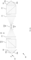
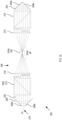
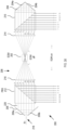
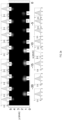
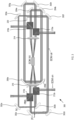
- Figures 2a to d show schematic illustrations of a demultiplexer 200 according to some example implementations of the present disclosure.
- the demultiplexer 200 generally comprises an electro-optic modulator (EOM) 202, a first mirror 204 and a second mirror 206.
- EOM electro-optic modulator
- the first mirror 204 comprises a first mirror component 204a and a second mirror component 204b.
- the second mirror 206 comprises a third mirror component 206a and a fourth mirror component 206b.
- a first polarizing beam-splitter 210 and a second polarizing beam-splitter 212 are provided. As will be appreciated, however, a single polarizing beam-splitter may be sufficient in order to couple light out of the optical trajectory 208 between the first mirror 204 and the second mirror 206.
- a first converging lens 214 is arranged in the optical trajectory between the electro-optic modulator 202 and the first poll beam-splitter 210
- a second converging lens 216 is arranged in the optical trajectory between the electro-optic modulator 202 and the second polarizing beam-splitter 212.
- h>) into the demultiplexer 200 is aligned parallel-displaced from a central axis of the telescope configuration formed by the first converging lens 214 and the second converging lens 216, which are, in this example, identical lenses, wherein the telescope configuration exhibits unit magnification.
- This slightly parallel-displaced alignment of the input path 218 with respect to the central axis of the telescope configuration with unit magnification results in the displacement being mirrored in its opposite direction at the output of the telescope. This results in a near-recurrent geometry for the input beam trajectory.
- the center (or center region) of the telescope contains, in this example, the active electro-optic modulator 202 (in some examples a Pockels cell) and the telescope itself is placed within polarizing beam-splitters 210 and 212.
- the active electro-optic modulator 202 in some examples a Pockels cell
- the telescope itself is placed within polarizing beam-splitters 210 and 212.
- a mirror 220 is arranged at an end of the optical trajectory to return all beams once again in the backwards travelling direction in order to double the number of output modes, as will be described further below.
- horizontally-polarized light pulses may traverse the polarizing beam-splitter 212, the telescope made of the two converging lenses 214 and 216, and the electro-optic modulator 202.
- the mirrors 204 and 206 with their respective components are used in order to align the beam trajectory so that after traversing through the polarizing beam-splitters, converging lenses and electro-optic modulator, as long as the electro-optic modulator is kept off, light returns back into the setup in a parallel-displaced trajectory, but now travelling in opposite directions (paths 2, 4, 6 and 8 shown in figure 2b ).
- This process continues repeating itself multiple times while the electro-optic modulator is kept off as long as the clear aperture of the optical elements allows it.
- the optical trajectory thus continues building up with a near-recurrent geometry and the light polarization is maintained, in this example, horizontal.
- a mirror 220 is placed, in this example, at normal incidence at the end of the optical trajectory so that all beams are returned once again in the backwards travelling direction.
- the number of output modes is therefore doubled (in this example 16 modes) for the same clear aperture size, as can be seen in figure 2c .
- the electro-optic modulator 202 is turned on, so that the polarization of light pulses are rotated, in this example, to its vertical direction.
- the polarizing beam-splitters 210 and 212 reflect the light pulses so that the light pulses are released from the original optical trajectory, thereby completing the demultiplexed protocol (see figure 2d ). All initial temporal delays between the input light pulses are erased by the setup geometry itself so that all light pulses are left synchronized. The light pulses are thus released onto different (synchronized) output trajectories, resulting in the demultiplexed signal.
- the demultiplexer allows for preparing a source of multiple indistinguishable single-photons e.g. ready to be plugged into and interfered in multimode interferometers for protocols within photonic quantum computing.
- An important application of the demultiplexer is thus the building of multi-photon sources for optical quantum information processing, although other applications are possible, as will be appreciated by those with skill in the art.
- the mirrors exhibit a reflectivity of more than 99.99% (that is less than 0.01% loss per element). Additionally or alternatively, the polarizing beam-splitters exhibit less than 1% loss per element. Additionally or alternatively, the converging lenses have less than 1% loss per element. Additionally or alternatively, the electro-optic modulator has less than 1% loss per element.
- the polarization contrast - ratio between s-polarized and p-polarized light transmission (reflection) - of the polarizing beam-splitter(s) is larger than 1000:1, for both the transmitted and reflected ports.
- the electro-optic modulator can reach an active polarization contrast of more than 100:1.
- the beam transverse spatial width can vary, and may be chosen, in some examples, to be approximately 2 mm diameter (relating to a 1/e intensity), to thereby maintain a Rayleigh range of several meters. This may be important, as the typical separation between light pulses is approximately 12.5 ns, i.e. approximately 4 m in a fixed timeframe.
- the Rayleigh range may hereby refer to the distance from the waist of a beam along its path, from its waist to a cross-section twice its area, at which point the cross-sectional radius is approximately 1.414 ( ⁇ 2) of the waist radius.
- the mirrors have a size of 1 inch or approximately 1 inch, and/or the polarizing beam-splitters have a size of 1 inch or approximately 1 inch.
- the two converging lenses have a focal length of 300 mm and a 2-inch size aperture. In examples in which a clear aperture needs to be increased, for example several polarizing beam-splitters may be stacked next to each other to achieve an effective larger aperture.
- the electro-optic modulator for example Pockels cell
- the electro-optic modulator can, in some examples, be switched from the OFF state to the ON state (and/or vice versa) in less than 10 ns. This may ensure that the switching time of the modulation is less than the standard 12.5 ns in 80 MHz repetition rate systems.
- a driving switching voltage along the Pockels cell is approximately 1 kV.
- the rise-time of the active element is the one directly impacting the system size. This is due to the travelling light pulses having to have their polarisation switched within the last round-trip of their trajectory, which means that the (time-equivalent) space of each round-trip should be smaller than the separation between pulses.
- Commercial state-of-the-art Pockels Cell can switch light polarisation with a switch time of approximately 10 ns. Hence, one can use standard laser/light systems with 80 MHz repetition rates (12.5 ns pulse separation).
- the demultiplexer 300 of figure 3 has a size of approximately 1.5 m times 0.5 m, in this example for a 12-output demultiplexer.
- Figure 4 shows a schematic block diagram of a system 400 according to some example implementations of the present disclosure.
- the demultiplexer 200, 300 is comprised in the system 400 (which may be a quantum computing system) together with a single-photon source 402 for generating a stream of single-photons, wherein the single-photon source 402 is coupled to the optical demultiplexer 200, 300 for providing, by the single-photon source 402 to the optical demultiplexer 200, 300, the stream of single-photons.
- the demultiplexer 200, 300 is configured to output a plurality of indistinguishable single-photons onto corresponding, respective ones of different output trajectories.
- Figure 5 shows a flow chart of a method 500 according to some example implementations of the present disclosure.
- the method 500 comprises, at step 502, providing a system, in particular a quantum computing system, comprising: an optical demultiplexer comprising: an electro-optic modulator configured to change, when the electro-optic modulator is in a first state, a polarization of light pulses having a first polarization and passing through the electro-optic modulator from the first polarization to a second polarization; a first mirror and a second mirror, wherein the electro-optic modulator is arranged in an optical trajectory between the first mirror and the second mirror for light pulses travelling in the optical trajectory between the first mirror and the second mirror to pass through the electro-optic modulator, wherein the first mirror and the second mirror are arranged in the optical demultiplexer such that light pulses travelling in the optical trajectory between the first mirror and the second mirror are displaced during each round of travelling forth and back between the first mirror and the second mirror; and a first polarizing beam-splitter arranged in the optical trajectory between the first mirror and the electro-optic modulator, wherein the
- the method 500 comprises providing, aligned parallel to and displaced from a central axis of the optical trajectory between the first mirror and the second mirror, a plurality of light pulses having a first polarization into the optical trajectory between the first mirror and the second mirror via the single-photon source.
- the method 500 comprises switching the electro-optic modulator from a second state, in which a polarization of the light pulses having the first polarization is not changed upon the light pulses passing through the electro-optic modulator, into the first state for changing the polarization of the light pulses from the first polarization to a second polarization.
- the method 500 comprises outputting the plurality of single-photons onto corresponding, respective ones of different output trajectories based on the first polarizing beam-splitter reflecting the light pulses having the second polarization to remove the light pulses from the optical trajectory between the first mirror and the second mirror.
- the light pulses may be output onto the corresponding, respective output trajectories.
- a beam transverse spatial width of the light pulses provided via the single-photon source may, in some examples, be 2 millimeters or approximately 2 millimeters.
- Figure 6 shows a flow chart of a method 600 according to some example implementations of the present disclosure.
- a demultiplexer or system according to any one of the example implementations as described herein is provided.
- a quantum computing operation is performed based on (i) light pulses output onto different output trajectories using the optical demultiplexer according to any one of the example implementations as described herein, or (ii) a plurality of single-photons output onto corresponding, respective ones of different output trajectories using the system according to any one of the example implementations as described herein.
- the module for time-space demultiplexing uses one single active element for routing an arbitrary number of time-modes within the same spatial mode onto different synchronised output spatial modes.
- a stream of light pulses, all in the same spatial mode, traversing the demultiplexer, is converted into various output trajectories, each simultaneously having one of such pulses.
- the demultiplexer comprises, in some examples, three types of optical elements: one or more polarising beam-splitters to spatially sort orthogonal polarisations, highly-reflective mirrors (with a reflectivity of, e.g., more than 99.99%), and one (ultra-fast) electro-optic modulator, in particular in the form of a Pockels Cell, with run speeds of more than 10 MHz.
- the protocol is divided, as outlined above, in a "loading" stage and a "releasing" stage. In the former, input (laser) pulses travel through an increasingly growing and near-recurrent geometry while the electro-optic modulator (Pockels Cell) is maintained OFF.
- the electro-optic modulator Pockels cell
- the electro-optic modulator is turned ON, which flips every pulse polarisation to an orthogonal state, now allowing them to be released from the recurrent geometry, and instead exit the device each in a different synchronised trajectory.
- the number of active elements needed is reduced for demultiplexing N pulses, typically N-1 active elements in existing alternatives, down to a single active element.
- the number of modes that can be demultiplexed is conceptually arbitrary, limited in practice only by the finite aperture of the optical elements in use.
- typically expensive high-voltage amplifiers and drivers, birefringent crystals, and complex multi-pulse electronics are all reduced to one of each case, hence reducing price, footprint size, and ease of implementation.
- the demultiplexer according to example implementations as described herein may be configured to demultiplex tens of outputs while always occupying the same footprint size.
- quantum computing may be achieved by encoding the calculation process into a specific complex entangled state by manipulating and measuring the entangled state in a specific order, including quantum state adjustment.
- Measurement-based quantum computing is a resource state that is quantum computed based on a highly entangled cluster state. The calculation itself may be achieved by continuously measuring adjacent quantum bits from the cluster state.
- the order of measurements, together with the measuring device, may define a computer system for universal quantum computing by effectively implementing arbitrary single-quantum bit and two-quantum bit (or multi-quantum bit) operations.
Landscapes
- Physics & Mathematics (AREA)
- Engineering & Computer Science (AREA)
- General Physics & Mathematics (AREA)
- Signal Processing (AREA)
- Computer Networks & Wireless Communication (AREA)
- Optics & Photonics (AREA)
- Theoretical Computer Science (AREA)
- Nonlinear Science (AREA)
- Electromagnetism (AREA)
- Data Mining & Analysis (AREA)
- Pure & Applied Mathematics (AREA)
- Computing Systems (AREA)
- General Engineering & Computer Science (AREA)
- Mathematical Physics (AREA)
- Software Systems (AREA)
- Mathematical Optimization (AREA)
- Mathematical Analysis (AREA)
- Evolutionary Computation (AREA)
- Condensed Matter Physics & Semiconductors (AREA)
- Computational Mathematics (AREA)
- Artificial Intelligence (AREA)
- Optical Modulation, Optical Deflection, Nonlinear Optics, Optical Demodulation, Optical Logic Elements (AREA)
Claims (15)
- Optischer Demultiplexer (200, 300), umfassend:einen elektrooptischen Modulator (202), der so konfiguriert ist, dass er, wenn sich der elektrooptische Modulator (202) in einem ersten Zustand befindet, eine Polarisation von Lichtimpulsen, die eine erste Polarisation aufweisen und durch den elektrooptischen Modulator (202) laufen, von der ersten Polarisation zu einer zweiten Polarisation ändert;einen ersten Spiegel (204) und einen zweiten Spiegel (206), wobei der elektrooptische Modulator (202) in einer optischen Trajektorie (208) zwischen dem ersten Spiegel (204) und dem zweiten Spiegel (206) angeordnet ist, damit Lichtimpulse, die sich in der optischen Trajektorie (208) zwischen dem ersten Spiegel (202) und dem zweiten Spiegel (206) bewegen, den elektrooptischen Modulator (202) durchlaufen, wobei der erste Spiegel (204) und der zweite Spiegel (206) in dem optischen Demultiplexer (200, 300) so angeordnet sind, dass die Lichtimpulse, die sich in der optischen Trajektorie (208) zwischen dem ersten Spiegel (204) und dem zweiten Spiegel (206) bewegen, senkrecht zu einer Ausbreitungsrichtung der Lichtimpulse zwischen dem ersten Spiegel (204) und dem zweiten Spiegel (206) während jeder Runde des Hin- und Zurücklaufens zwischen dem ersten Spiegel (204) und dem zweiten Spiegel (206) verschoben werden; undeinen ersten polarisierenden Strahlteiler (210), der in der optischen Trajektorie zwischen dem ersten Spiegel (204) und dem elektrooptischen Modulator (202) angeordnet ist, wobei der erste polarisierende Strahlteiler (210) so konfiguriert ist, dass er:Lichtimpulse mit der ersten Polarisation weiterleitet, undLichtimpulse mit der zweiten Polarisation reflektiert, um die Lichtimpulse mit der zweiten Polarisation aus der optischen Trajektorie (208) zwischen dem ersten Spiegel (204) und dem zweiten Spiegel (206) zu entfernen, wobei der erste polarisierende Strahlteiler (210) so konfiguriert ist, dass er die Lichtimpulse, die in Bezug zueinander senkrecht zur Ausbreitungsrichtung verschoben sind, auf unterschiedliche, jeweilige Ausgangstrajektorien reflektiert;wobei der optische Demultiplexer (200, 300) ferner einen dritten Spiegel (220) umfasst, der an einem Ende der optischen Trajektorie bei senkrechtem Einfall in Bezug auf die optische Trajektorie an einem Endabschnitt der optischen Trajektorie angeordnet ist, um Lichtimpulse zu reflektieren, die sich in der entgegengesetzten Richtung zwischen dem ersten Spiegel (204) und dem zweiten Spiegel (206) bewegen.
- Optischer Demultiplexer (200, 300) nach Anspruch 1, ferner umfassend einen zweiten polarisierenden Strahlteiler (212), der in der optischen Trajektorie zwischen dem zweiten Spiegel (206) und dem elektrooptischen Modulator (202) angeordnet ist, wobei der zweite polarisierende Strahlteiler (212) so konfiguriert ist, dass er:Lichtimpulse mit der ersten Polarisation weiterleitet, undLichtimpulse mit der zweiten Polarisation reflektiert, um die Lichtimpulse mit der zweiten Polarisation aus der optischen Trajektorie (208) zwischen dem ersten Spiegel (204) und dem zweiten Spiegel (206) zu entfernen, wobei der zweite polarisierende Strahlteiler (212) so konfiguriert ist, dass er die Lichtimpulse, die in Bezug zueinander senkrecht zur Ausbreitungsrichtung verschoben sind, auf unterschiedliche, jeweilige Ausgangstrajektorien reflektiert.
- Optischer Demultiplexer (200, 300) nach Anspruch 1 oder 2, ferner umfassend eine erste Sammellinse (214), die in der optischen Trajektorie zwischen dem elektrooptischen Modulator (202) und dem ersten polarisierenden Strahlteiler (210) angeordnet ist, wobei die erste Sammellinse (214) so konfiguriert ist, dass sie Lichtimpulse, die sich in der optischen Trajektorie von dem elektrooptischen Modulator (202) zu der ersten Sammellinse (214) bewegen, konvergiert, damit die Lichtimpulse, die in Bezug zueinander senkrecht zu der Ausbreitungsrichtung verschoben sind, sich parallel in Bezug zueinander zwischen der ersten Sammellinse (214) und dem ersten polarisierenden Strahlteiler (210) bewegen.
- Optischer Demultiplexer (200, 300) nach Anspruch 3, ferner umfassend eine zweite Sammellinse (216), die in der optischen Trajektorie zwischen dem elektrooptischen Modulator (202) und dem zweiten Spiegel (206) angeordnet ist, wobei die zweite Sammellinse (216) so konfiguriert ist, dass sie Lichtimpulse, die sich in der optischen Trajektorie von dem elektrooptischen Modulator (202) zu der zweiten Sammellinse (216) bewegen, konvergiert, damit die Lichtimpulse, die in Bezug zueinander senkrecht zu der Ausbreitungsrichtung verschoben sind, sich parallel in Bezug zueinander zwischen der zweiten Sammellinse (216) und dem zweiten Spiegel (206) bewegen.
- Optischer Demultiplexer (200, 300) nach Anspruch 4, wenn er von Anspruch 2 abhängt, wobei die zweite Sammellinse (216) in der optischen Trajektorie zwischen dem elektrooptischen Modulator (202) und dem zweiten polarisierenden Strahlteiler (212) angeordnet ist, wobei die zweite Sammellinse (216) so konfiguriert ist, dass sie Lichtimpulse, die sich in der optischen Trajektorie von dem elektrooptischen Modulator (202) zu der zweiten Sammellinse (216) bewegen, konvergiert, damit die Lichtimpulse, die in Bezug zueinander senkrecht zur Ausbreitungsrichtung verschoben sind, sich parallel zueinander zwischen der zweiten Sammellinse (216) und dem zweiten polarisierenden Strahlteiler (212) bewegen.
- Optischer Demultiplexer (200, 300) nach Anspruch 4 oder 5, wobei die erste Sammellinse (214) und die zweite Sammellinse (216) in dem optischen Demultiplexer (200, 300) in einer Teleskopkonfiguration mit Einheitsvergrößerung angeordnet sind,
wobei ein Eingangsweg (218) in den optischen Demultiplexer (200, 300) für Lichtimpulse, die sich in der optischen Trajektorie (208) zwischen dem ersten Spiegel (204) und dem zweiten Spiegel (206) bewegen, parallel zu einer zentralen Achse der Teleskopkonfiguration ausgerichtet und von dieser versetzt ist, und/oder wobei der elektrooptische Modulator (202) in einem Zentrum oder mittleren Bereich der Teleskopkonfiguration angeordnet ist. - Optischer Demultiplexer (200, 300) nach einem der Ansprüche 3 bis 6, wobei der erste Spiegel (204) eine erste Spiegelkomponente (204a) und eine zweite Spiegelkomponente (204b) zum Reflektieren von Lichtimpulsen umfasst, die sich in der optischen Trajektorie von der ersten Sammellinse (214) zu dem ersten Spiegel (204) bewegen, wobei die erste Spiegelkomponente (204a) und die zweite Spiegelkomponente (204b) senkrecht oder im Wesentlichen senkrecht zueinander ausgerichtet sind, und wobei die erste Spiegelkomponente (204a) und die zweite Spiegelkomponente (204b) in einem Winkel von 45 Grad oder im Wesentlichen 45 Grad in Bezug auf die optische Trajektorie ausgerichtet sind, auf der sich die Lichtimpulse parallel zueinander zwischen der ersten Sammellinse (214) und dem ersten Spiegel (204) bewegen.
- Optischer Demultiplexer (200, 300) nach Anspruch 7, wenn er von Anspruch 4 abhängt, wobei der zweite Spiegel (206) eine dritte Spiegelkomponente (206a) und eine vierte Spiegelkomponente (206b) zum Reflektieren von Lichtimpulsen umfasst, die sich in der optischen Trajektorie von der zweiten Sammellinse (216) zu dem zweiten Spiegel (206) bewegen, wobei die dritte Spiegelkomponente (206a) und die vierte Spiegelkomponente (206b) senkrecht oder im Wesentlichen senkrecht zueinander ausgerichtet sind, und wobei die dritte Spiegelkomponente (206a) und die vierte Spiegelkomponente (206b) in einem Winkel von 45 Grad oder im Wesentlichen 45 Grad in Bezug auf die optische Trajektorie ausgerichtet sind, auf der sich die Lichtimpulse parallel zueinander zwischen der zweiten Sammellinse (216) und dem zweiten Spiegel (206) bewegen.
- Optischer Demultiplexer (200, 300) nach einem der vorhergehenden Ansprüche, wobei einer oder beide, der erste Spiegel (204) und der zweite Spiegel (206), eine Öffnung für Lichtimpulse aufweisen, die in die optische Trajektorie (208) zwischen dem ersten Spiegel (204) und dem zweiten Spiegel (206) eingebracht werden.
- Optischer Demultiplexer (200, 300) nach einem der vorhergehenden Ansprüche, wobei der optische Demultiplexer (200, 300) so konfiguriert ist, dass er über den ersten polarisierenden Strahlteiler (210) Lichtimpulse mit unterschiedlichen zeitlichen Moden und einer gleichen räumlichen Mode von der optischen Trajektorie auf unterschiedliche räumliche Moden entfernt, wenn der elektrooptische Modulator (202) von einem zweiten Zustand, in dem die Polarisation der Lichtimpulse mit der ersten Polarisation beim Durchgang der Lichtimpulse durch den elektrooptischen Modulator (202) nicht verändert wird, in den ersten Zustand geschaltet wird,wobei, basierend darauf, dass alle Lichtpulse, die sich auf der optischen Trajektorie (208) zwischen dem ersten Spiegel (204) und dem zweiten Spiegel (206) bewegen, die erste Polarisation aufweisen, und darauf, dass der elektrooptische Modulator (202) von dem zweiten Zustand in den ersten Zustand geschaltet wird, damit die Polarisation aller Lichtpulse von der ersten Polarisation in die zweite Polarisation geändert wird, wenn sie sich durch den elektrooptischen Modulator (202) in dem ersten Zustand bewegen, der erste polarisierende Strahlteiler (210) so konfiguriert ist, dass er alle Lichtimpulse gleichzeitig oder innerhalb von weniger als 10 Nanosekunden aus der optischen Trajektorie (208) zwischen dem ersten Spiegel (204) und dem zweiten Spiegel (206) entfernt,wobei, wenn der elektrooptische Modulator (202) vom zweiten Zustand in den ersten Zustand geschaltet wird, der erste polarisierende Strahlteiler (210) so konfiguriert ist, dass er alle Lichtimpulse gleichzeitig oder innerhalb von weniger als 10 Nanosekunden aus der optischen Trajektorie (208) zwischen dem ersten Spiegel (204) und dem zweiten Spiegel (206) entfernt, wobei jede der Ausgangstrajektorien einen einzelnen der Lichtimpulse enthält.
- Optischer Demultiplexer (200, 300) nach einem der vorhergehenden Ansprüche, wobei der elektrooptische Modulator (202) eine Pockels-Zelle umfasst, und wobei sich der erste Zustand auf einen Zustand bezieht, in dem die Pockels-Zelle eingeschaltet ist,
wobei der elektrooptische Modulator (202) zwischen dem ersten Zustand, in dem die Polarisation der Lichtimpulse mit der ersten Polarisation beim Durchlaufen der Lichtimpulse durch den elektrooptischen Modulator (202) geändert wird, und einem zweiten Zustand, in dem die Polarisation der Lichtimpulse mit der ersten Polarisation beim Durchlaufen der Lichtimpulse durch den elektrooptischen Modulator (202) nicht geändert wird, in weniger als 10 Nanosekunden umschaltbar ist. - Optischer Demultiplexer (200, 300) nach einem der vorhergehenden Ansprüche, ferner umfassend einen Satz weiterer Spiegel (320a-320h), die in der optischen Trajektorie angeordnet sind, um die optische Trajektorie in einem Bereich mit Abmessungen von 1,5 Metern oder weniger mal 0,5 Metern oder weniger für eine optische Trajektorienlänge von mindestens 6 Metern zu begrenzen.
- Quantencomputersystem mit dem optischen Demultiplexer (200, 300) nach einem der vorhergehenden Ansprüche.
- System (400), insbesondere ein Quantencomputersystem, umfassend:den optischen Demultiplexer (200, 300) nach einem der Ansprüche 1 bis 12;eine Einzelphotonenquelle (402) zum Erzeugen eines Stroms von Einzelphotonen, wobei die Einzelphotonenquelle (402) mit dem optischen Demultiplexer (200, 300) gekoppelt ist, um den Strom von Einzelphotonen durch die Einzelphotonenquelle (402) an den optischen Demultiplexer (200, 300) zu liefern, undwobei der optische Demultiplexer (200, 300) so konfiguriert ist, dass er eine Mehrzahl von nicht unterscheidbaren Einzelphotonen auf entsprechende, jeweilige der verschiedenen Ausgangstrajektorien ausgibt.
- Verfahren (500) zum Ausgeben einer Mehrzahl von Einzelphotonen auf entsprechende, jeweilige unterschiedliche Ausgangstrajektorien, wobei das Verfahren umfasst:Bereitstellen (502) des Systems nach Anspruch 14;Bereitstellen (504) einer Mehrzahl von Lichtimpulsen mit einer ersten Polarisation in die optische Trajektorie zwischen dem ersten Spiegel und dem zweiten Spiegel über die Einzelphotonenquelle, die parallel zu und versetzt von einer zentralen Achse der optischen Trajektorie zwischen dem ersten Spiegel und dem zweiten Spiegel ausgerichtet sind,Umschalten (506) des elektrooptischen Modulators aus einem zweiten Zustand, in dem eine Polarisation der Lichtimpulse mit der ersten Polarisation beim Durchgang der Lichtimpulse durch den elektrooptischen Modulator nicht geändert wird, in den ersten Zustand zum Ändern der Polarisation der Lichtimpulse von der ersten Polarisation in eine zweite Polarisation; undAusgeben (508) der Mehrzahl von Einzelphotonen auf entsprechende, jeweils unterschiedliche Ausgangstrajektorien basierend auf dem ersten polarisierenden Strahlteiler, der die Lichtpulse mit der zweiten Polarisation reflektiert, um die Lichtpulse aus der optischen Trajektorie zwischen dem ersten Spiegel und dem zweiten Spiegel zu entfernen.
Applications Claiming Priority (1)
| Application Number | Priority Date | Filing Date | Title |
|---|---|---|---|
| PCT/EP2022/057326 WO2023179841A1 (en) | 2022-03-21 | 2022-03-21 | Demultiplexer and method of use thereof |
Publications (3)
| Publication Number | Publication Date |
|---|---|
| EP4275091A1 EP4275091A1 (de) | 2023-11-15 |
| EP4275091B1 true EP4275091B1 (de) | 2025-05-07 |
| EP4275091C0 EP4275091C0 (de) | 2025-05-07 |
Family
ID=81328412
Family Applications (1)
| Application Number | Title | Priority Date | Filing Date |
|---|---|---|---|
| EP22717117.0A Active EP4275091B1 (de) | 2022-03-21 | 2022-03-21 | Demultplexer und verfahren zur verwendung davon |
Country Status (6)
| Country | Link |
|---|---|
| US (1) | US12607883B2 (de) |
| EP (1) | EP4275091B1 (de) |
| JP (1) | JP7632663B2 (de) |
| KR (1) | KR102784643B1 (de) |
| CN (1) | CN117157568A (de) |
| WO (1) | WO2023179841A1 (de) |
Family Cites Families (21)
| Publication number | Priority date | Publication date | Assignee | Title |
|---|---|---|---|---|
| JPS57151917A (en) * | 1981-03-17 | 1982-09-20 | Ricoh Co Ltd | Optical switch device |
| US6389045B1 (en) * | 1999-04-19 | 2002-05-14 | Lambda Physik Ag | Optical pulse stretching and smoothing for ArF and F2 lithography excimer lasers |
| US6285500B1 (en) | 1999-06-29 | 2001-09-04 | Corning Incorporated | Wavelength selective switch |
| JP2002107683A (ja) | 2000-09-28 | 2002-04-10 | Tdk Corp | 光制御装置 |
| JP2003051635A (ja) | 2001-08-03 | 2003-02-21 | Kitakyushu Foundation For The Advancement Of Industry Science & Technology | プリズムを用いるマルチパスラマンセル |
| JP4051324B2 (ja) | 2003-08-12 | 2008-02-20 | 日本電信電話株式会社 | 光信号処理装置および光信号処理方法 |
| CN1651947A (zh) * | 2004-02-02 | 2005-08-10 | 中国科学技术大学 | 一种偏振控制编码方法、编码器和量子密钥分配系统 |
| JP4296167B2 (ja) | 2005-09-29 | 2009-07-15 | 株式会社東芝 | 量子計算機及び量子計算方法 |
| JP4702292B2 (ja) | 2007-01-23 | 2011-06-15 | セイコーエプソン株式会社 | 光源装置、照明装置、モニタ装置、及び画像表示装置 |
| US7400658B1 (en) * | 2007-03-08 | 2008-07-15 | Coherent, Inc. | Quasi-CW UV laser with low peak pulse-power |
| US20130077086A1 (en) | 2011-09-23 | 2013-03-28 | Kla-Tencor Corporation | Solid-State Laser And Inspection System Using 193nm Laser |
| JP2013084971A (ja) | 2012-12-03 | 2013-05-09 | Gigaphoton Inc | 極端紫外光源用ドライバレーザ |
| US9525265B2 (en) | 2014-06-20 | 2016-12-20 | Kla-Tencor Corporation | Laser repetition rate multiplier and flat-top beam profile generators using mirrors and/or prisms |
| CN105652476A (zh) | 2016-04-01 | 2016-06-08 | 华南师范大学 | 一种内禀稳定的光强调制系统及调制方法 |
| CN107370546B (zh) | 2016-05-11 | 2020-06-26 | 阿里巴巴集团控股有限公司 | 窃听检测方法、数据发送方法、装置及系统 |
| CN109791257B (zh) * | 2016-10-07 | 2020-06-05 | 光联通讯技术有限公司美国分部 | 波长选择开关 |
| US11592393B2 (en) * | 2018-11-21 | 2023-02-28 | The Board Of Trustees Of The Leland Stanford Junior University | Wide-field nanosecond imaging methods using wide-field optical modulators |
| CN110460388B (zh) * | 2019-06-18 | 2024-07-19 | 中国电子科技集团公司电子科学研究院 | 时间相位解码装置和包括其的量子密钥分发系统 |
| US12003072B2 (en) | 2019-07-16 | 2024-06-04 | Nichia Corporation | Q switch resonator, and pulse generator |
| CN210867715U (zh) * | 2019-10-09 | 2020-06-26 | 中国电子科技集团公司电子科学研究院 | 相位调制偏振编解码装置和量子密钥分发系统 |
| GB2593456B (en) | 2020-03-18 | 2024-02-28 | Thermo Fisher Scient Ecublens Sarl | Double-pulse laser system |
-
2022
- 2022-03-21 WO PCT/EP2022/057326 patent/WO2023179841A1/en not_active Ceased
- 2022-03-21 EP EP22717117.0A patent/EP4275091B1/de active Active
- 2022-03-21 CN CN202280007988.7A patent/CN117157568A/zh active Pending
- 2022-03-21 KR KR1020237017233A patent/KR102784643B1/ko active Active
- 2022-03-21 JP JP2023548832A patent/JP7632663B2/ja active Active
-
2023
- 2023-05-16 US US18/198,176 patent/US12607883B2/en active Active
Also Published As
| Publication number | Publication date |
|---|---|
| JP2024518216A (ja) | 2024-05-01 |
| WO2023179841A1 (en) | 2023-09-28 |
| EP4275091A1 (de) | 2023-11-15 |
| US12607883B2 (en) | 2026-04-21 |
| US20230296926A1 (en) | 2023-09-21 |
| CN117157568A (zh) | 2023-12-01 |
| JP7632663B2 (ja) | 2025-02-19 |
| KR20230138943A (ko) | 2023-10-05 |
| KR102784643B1 (ko) | 2025-03-19 |
| EP4275091C0 (de) | 2025-05-07 |
Similar Documents
| Publication | Publication Date | Title |
|---|---|---|
| US10222822B2 (en) | Photonic quantum memory with polarization-to-time entanglement conversion and time-to-polarization entanglement conversion | |
| CN112750681B (zh) | 一种离子阱系统及离子操控方法 | |
| US7787720B2 (en) | Wavelength selective reconfigurable optical cross-connect | |
| Riza et al. | Reconfigurable wavelength add-drop filtering based on a Banyan network topology and ferroelectric liquid crystal fiber-optic switches | |
| EP0435296B1 (de) | Optischer räumlicher Schalter und Netzwerk mit derartigen optischen räumlichen Schaltern | |
| US10495819B2 (en) | Optical arrangement for managing diversity and isolation between ports in a wavelength selective switch | |
| CN112883534B (zh) | 一种光计算设备以及光信号处理方法 | |
| WO2013009946A1 (en) | Chip integrated single photon generation by active time multiplexing | |
| CN114185135B (zh) | 一种折叠型m×n端口波长选择开关的实现方法 | |
| US10110313B2 (en) | Optical switching apparatus, optical cross-connect node, and optical signal switching method | |
| US20040136646A1 (en) | All optical decoding systems for decoding optical encoded data symbols across multiple decoding layers | |
| EP4275091B1 (de) | Demultplexer und verfahren zur verwendung davon | |
| US20040208571A1 (en) | All optical cross routing using decoding systems for optical encoded data symbols | |
| WO2001001189A9 (en) | All-optical interconnect utilizing polarization gates | |
| RU242683U1 (ru) | Пространственно-временной демультиплексор с высокой устойчивостью к оптическим потерям | |
| Lee et al. | Multi-wavelength message routing in a non-blocking four-port bidirectional switch fabric for silicon photonic networks-on-chip | |
| CN112952533A (zh) | 一种混合型多路复用单光子源的制备装置及工作方法 | |
| EP4554118A1 (de) | Optische verbindungsvorrichtung | |
| CN218632778U (zh) | 一种被动锁模超短脉冲激光器 | |
| CA3192558C (en) | Apparatus comprising one or more photonic memories | |
| Snowbell et al. | Efficient self-aligning multibeam coupling into a single-mode fiber | |
| JP3023221B2 (ja) | 多端子光スイッチ | |
| GB2614816A (en) | Apparatus comprising one or more photonic memories | |
| Ashraf | OPTICAL PACKET SWITCHING BASED ON TURBO SWITCHES USING SPACE SWITCH ARRAY | |
| JPH08288948A (ja) | 光atmスイッチ |
Legal Events
| Date | Code | Title | Description |
|---|---|---|---|
| STAA | Information on the status of an ep patent application or granted ep patent |
Free format text: STATUS: UNKNOWN |
|
| STAA | Information on the status of an ep patent application or granted ep patent |
Free format text: STATUS: THE INTERNATIONAL PUBLICATION HAS BEEN MADE |
|
| PUAI | Public reference made under article 153(3) epc to a published international application that has entered the european phase |
Free format text: ORIGINAL CODE: 0009012 |
|
| STAA | Information on the status of an ep patent application or granted ep patent |
Free format text: STATUS: REQUEST FOR EXAMINATION WAS MADE |
|
| 17P | Request for examination filed |
Effective date: 20230626 |
|
| AK | Designated contracting states |
Kind code of ref document: A1 Designated state(s): AL AT BE BG CH CY CZ DE DK EE ES FI FR GB GR HR HU IE IS IT LI LT LU LV MC MK MT NL NO PL PT RO RS SE SI SK SM TR |
|
| GRAP | Despatch of communication of intention to grant a patent |
Free format text: ORIGINAL CODE: EPIDOSNIGR1 |
|
| STAA | Information on the status of an ep patent application or granted ep patent |
Free format text: STATUS: GRANT OF PATENT IS INTENDED |
|
| DAV | Request for validation of the european patent (deleted) | ||
| DAX | Request for extension of the european patent (deleted) | ||
| INTG | Intention to grant announced |
Effective date: 20241206 |
|
| GRAS | Grant fee paid |
Free format text: ORIGINAL CODE: EPIDOSNIGR3 |
|
| GRAA | (expected) grant |
Free format text: ORIGINAL CODE: 0009210 |
|
| STAA | Information on the status of an ep patent application or granted ep patent |
Free format text: STATUS: THE PATENT HAS BEEN GRANTED |
|
| AK | Designated contracting states |
Kind code of ref document: B1 Designated state(s): AL AT BE BG CH CY CZ DE DK EE ES FI FR GB GR HR HU IE IS IT LI LT LU LV MC MK MT NL NO PL PT RO RS SE SI SK SM TR |
|
| REG | Reference to a national code |
Ref country code: GB Ref legal event code: FG4D |
|
| REG | Reference to a national code |
Ref country code: CH Ref legal event code: EP |
|
| REG | Reference to a national code |
Ref country code: DE Ref legal event code: R096 Ref document number: 602022014312 Country of ref document: DE |
|
| REG | Reference to a national code |
Ref country code: IE Ref legal event code: FG4D |
|
| U01 | Request for unitary effect filed |
Effective date: 20250602 |
|
| U07 | Unitary effect registered |
Designated state(s): AT BE BG DE DK EE FI FR IT LT LU LV MT NL PT RO SE SI Effective date: 20250606 |
|
| PG25 | Lapsed in a contracting state [announced via postgrant information from national office to epo] |
Ref country code: ES Free format text: LAPSE BECAUSE OF FAILURE TO SUBMIT A TRANSLATION OF THE DESCRIPTION OR TO PAY THE FEE WITHIN THE PRESCRIBED TIME-LIMIT Effective date: 20250507 |
|
| PG25 | Lapsed in a contracting state [announced via postgrant information from national office to epo] |
Ref country code: GR Free format text: LAPSE BECAUSE OF FAILURE TO SUBMIT A TRANSLATION OF THE DESCRIPTION OR TO PAY THE FEE WITHIN THE PRESCRIBED TIME-LIMIT Effective date: 20250808 Ref country code: NO Free format text: LAPSE BECAUSE OF FAILURE TO SUBMIT A TRANSLATION OF THE DESCRIPTION OR TO PAY THE FEE WITHIN THE PRESCRIBED TIME-LIMIT Effective date: 20250807 |
|
| PG25 | Lapsed in a contracting state [announced via postgrant information from national office to epo] |
Ref country code: PL Free format text: LAPSE BECAUSE OF FAILURE TO SUBMIT A TRANSLATION OF THE DESCRIPTION OR TO PAY THE FEE WITHIN THE PRESCRIBED TIME-LIMIT Effective date: 20250507 |
|
| PG25 | Lapsed in a contracting state [announced via postgrant information from national office to epo] |
Ref country code: HR Free format text: LAPSE BECAUSE OF FAILURE TO SUBMIT A TRANSLATION OF THE DESCRIPTION OR TO PAY THE FEE WITHIN THE PRESCRIBED TIME-LIMIT Effective date: 20250507 |
|
| PG25 | Lapsed in a contracting state [announced via postgrant information from national office to epo] |
Ref country code: RS Free format text: LAPSE BECAUSE OF FAILURE TO SUBMIT A TRANSLATION OF THE DESCRIPTION OR TO PAY THE FEE WITHIN THE PRESCRIBED TIME-LIMIT Effective date: 20250807 |
|
| PG25 | Lapsed in a contracting state [announced via postgrant information from national office to epo] |
Ref country code: IS Free format text: LAPSE BECAUSE OF FAILURE TO SUBMIT A TRANSLATION OF THE DESCRIPTION OR TO PAY THE FEE WITHIN THE PRESCRIBED TIME-LIMIT Effective date: 20250907 |
|
| PG25 | Lapsed in a contracting state [announced via postgrant information from national office to epo] |
Ref country code: SM Free format text: LAPSE BECAUSE OF FAILURE TO SUBMIT A TRANSLATION OF THE DESCRIPTION OR TO PAY THE FEE WITHIN THE PRESCRIBED TIME-LIMIT Effective date: 20250507 |
|
| PG25 | Lapsed in a contracting state [announced via postgrant information from national office to epo] |
Ref country code: CZ Free format text: LAPSE BECAUSE OF FAILURE TO SUBMIT A TRANSLATION OF THE DESCRIPTION OR TO PAY THE FEE WITHIN THE PRESCRIBED TIME-LIMIT Effective date: 20250507 |
|
| PG25 | Lapsed in a contracting state [announced via postgrant information from national office to epo] |
Ref country code: SK Free format text: LAPSE BECAUSE OF FAILURE TO SUBMIT A TRANSLATION OF THE DESCRIPTION OR TO PAY THE FEE WITHIN THE PRESCRIBED TIME-LIMIT Effective date: 20250507 |
|
| PLBE | No opposition filed within time limit |
Free format text: ORIGINAL CODE: 0009261 |
|
| STAA | Information on the status of an ep patent application or granted ep patent |
Free format text: STATUS: NO OPPOSITION FILED WITHIN TIME LIMIT |
|
| REG | Reference to a national code |
Ref country code: CH Ref legal event code: L10 Free format text: ST27 STATUS EVENT CODE: U-0-0-L10-L00 (AS PROVIDED BY THE NATIONAL OFFICE) Effective date: 20260318 |
|
| PGFP | Annual fee paid to national office [announced via postgrant information from national office to epo] |
Ref country code: GB Payment date: 20260324 Year of fee payment: 5 |
|
| 26N | No opposition filed |
Effective date: 20260210 |