EP4274089A1 - Efficiency optimization of maximum torque per amps control for synchronous motors - Google Patents
Efficiency optimization of maximum torque per amps control for synchronous motors Download PDFInfo
- Publication number
- EP4274089A1 EP4274089A1 EP23171687.9A EP23171687A EP4274089A1 EP 4274089 A1 EP4274089 A1 EP 4274089A1 EP 23171687 A EP23171687 A EP 23171687A EP 4274089 A1 EP4274089 A1 EP 4274089A1
- Authority
- EP
- European Patent Office
- Prior art keywords
- axis reference
- reference current
- current
- axis
- motor
- Prior art date
- Legal status (The legal status is an assumption and is not a legal conclusion. Google has not performed a legal analysis and makes no representation as to the accuracy of the status listed.)
- Pending
Links
- 230000001360 synchronised effect Effects 0.000 title claims description 5
- 238000005457 optimization Methods 0.000 title description 11
- 238000000034 method Methods 0.000 claims abstract description 51
- 230000004907 flux Effects 0.000 claims description 31
- 210000003127 knee Anatomy 0.000 claims description 3
- 238000010586 diagram Methods 0.000 description 13
- 230000008569 process Effects 0.000 description 12
- 230000006870 function Effects 0.000 description 5
- 230000006872 improvement Effects 0.000 description 5
- 238000004364 calculation method Methods 0.000 description 4
- 238000013213 extrapolation Methods 0.000 description 4
- 238000010845 search algorithm Methods 0.000 description 4
- 238000004590 computer program Methods 0.000 description 3
- 239000003990 capacitor Substances 0.000 description 2
- 238000004891 communication Methods 0.000 description 2
- 230000004048 modification Effects 0.000 description 2
- 238000012986 modification Methods 0.000 description 2
- 230000003287 optical effect Effects 0.000 description 2
- 230000003247 decreasing effect Effects 0.000 description 1
- 230000007935 neutral effect Effects 0.000 description 1
- 230000004044 response Effects 0.000 description 1
- 239000004065 semiconductor Substances 0.000 description 1
- 238000004804 winding Methods 0.000 description 1
Images


Classifications
-
- H—ELECTRICITY
- H02—GENERATION; CONVERSION OR DISTRIBUTION OF ELECTRIC POWER
- H02P—CONTROL OR REGULATION OF ELECTRIC MOTORS, ELECTRIC GENERATORS OR DYNAMO-ELECTRIC CONVERTERS; CONTROLLING TRANSFORMERS, REACTORS OR CHOKE COILS
- H02P6/00—Arrangements for controlling synchronous motors or other dynamo-electric motors using electronic commutation dependent on the rotor position; Electronic commutators therefor
- H02P6/08—Arrangements for controlling the speed or torque of a single motor
-
- H—ELECTRICITY
- H02—GENERATION; CONVERSION OR DISTRIBUTION OF ELECTRIC POWER
- H02P—CONTROL OR REGULATION OF ELECTRIC MOTORS, ELECTRIC GENERATORS OR DYNAMO-ELECTRIC CONVERTERS; CONTROLLING TRANSFORMERS, REACTORS OR CHOKE COILS
- H02P21/00—Arrangements or methods for the control of electric machines by vector control, e.g. by control of field orientation
- H02P21/14—Estimation or adaptation of machine parameters, e.g. flux, current or voltage
- H02P21/20—Estimation of torque
-
- H—ELECTRICITY
- H02—GENERATION; CONVERSION OR DISTRIBUTION OF ELECTRIC POWER
- H02P—CONTROL OR REGULATION OF ELECTRIC MOTORS, ELECTRIC GENERATORS OR DYNAMO-ELECTRIC CONVERTERS; CONTROLLING TRANSFORMERS, REACTORS OR CHOKE COILS
- H02P21/00—Arrangements or methods for the control of electric machines by vector control, e.g. by control of field orientation
- H02P21/0003—Control strategies in general, e.g. linear type, e.g. P, PI, PID, using robust control
- H02P21/0025—Control strategies in general, e.g. linear type, e.g. P, PI, PID, using robust control implementing a off line learning phase to determine and store useful data for on-line control
-
- H—ELECTRICITY
- H02—GENERATION; CONVERSION OR DISTRIBUTION OF ELECTRIC POWER
- H02P—CONTROL OR REGULATION OF ELECTRIC MOTORS, ELECTRIC GENERATORS OR DYNAMO-ELECTRIC CONVERTERS; CONTROLLING TRANSFORMERS, REACTORS OR CHOKE COILS
- H02P21/00—Arrangements or methods for the control of electric machines by vector control, e.g. by control of field orientation
- H02P21/14—Estimation or adaptation of machine parameters, e.g. flux, current or voltage
-
- H—ELECTRICITY
- H02—GENERATION; CONVERSION OR DISTRIBUTION OF ELECTRIC POWER
- H02P—CONTROL OR REGULATION OF ELECTRIC MOTORS, ELECTRIC GENERATORS OR DYNAMO-ELECTRIC CONVERTERS; CONTROLLING TRANSFORMERS, REACTORS OR CHOKE COILS
- H02P21/00—Arrangements or methods for the control of electric machines by vector control, e.g. by control of field orientation
- H02P21/22—Current control, e.g. using a current control loop
-
- H—ELECTRICITY
- H02—GENERATION; CONVERSION OR DISTRIBUTION OF ELECTRIC POWER
- H02P—CONTROL OR REGULATION OF ELECTRIC MOTORS, ELECTRIC GENERATORS OR DYNAMO-ELECTRIC CONVERTERS; CONTROLLING TRANSFORMERS, REACTORS OR CHOKE COILS
- H02P25/00—Arrangements or methods for the control of AC motors characterised by the kind of AC motor or by structural details
- H02P25/02—Arrangements or methods for the control of AC motors characterised by the kind of AC motor or by structural details characterised by the kind of motor
- H02P25/022—Synchronous motors
-
- H—ELECTRICITY
- H02—GENERATION; CONVERSION OR DISTRIBUTION OF ELECTRIC POWER
- H02P—CONTROL OR REGULATION OF ELECTRIC MOTORS, ELECTRIC GENERATORS OR DYNAMO-ELECTRIC CONVERTERS; CONTROLLING TRANSFORMERS, REACTORS OR CHOKE COILS
- H02P6/00—Arrangements for controlling synchronous motors or other dynamo-electric motors using electronic commutation dependent on the rotor position; Electronic commutators therefor
- H02P6/28—Arrangements for controlling current
-
- H—ELECTRICITY
- H02—GENERATION; CONVERSION OR DISTRIBUTION OF ELECTRIC POWER
- H02P—CONTROL OR REGULATION OF ELECTRIC MOTORS, ELECTRIC GENERATORS OR DYNAMO-ELECTRIC CONVERTERS; CONTROLLING TRANSFORMERS, REACTORS OR CHOKE COILS
- H02P2207/00—Indexing scheme relating to controlling arrangements characterised by the type of motor
- H02P2207/05—Synchronous machines, e.g. with permanent magnets or DC excitation
- H02P2207/055—Surface mounted magnet motors
Definitions
- the subject matter disclosed herein relates to improving and/or optimizing Maximum Torque per Amps (MTPA) control.
- MTPA Maximum Torque per Amps
- a method for improving MTPA controls disclosed.
- the method generates an offline MTPA curve based on an autotune test for a motor.
- the method generates a search zone for the MTPA curve for a given torque point.
- the search zone includes an upper D-axis reference current and a lower D-axis reference current for the given torque point.
- the MTPA curve comprises torque points of torques for current pairs of a Q-axis current and a D-axis current for the motor.
- the method iteratively modifies a D-axis reference current between the upper D-axis reference current and the lower D-axis reference current of the search zone.
- the method modifies a Q-axis reference current to output the given torque.
- the method updates a corresponding current pair of the given torque point to the modified D-axis reference current and the modified Q-axis reference current with a lowest current amplitude to further improve the efficiency of the motor.
- the apparatus includes a controller.
- the controller generates an offline MTPA curve based on an autotune test for a motor.
- the controller generates a search zone for the MTPA curve for a given torque point.
- the search zone includes an upper D-axis reference current and a lower D-axis reference current for the given torque point.
- the MTPA curve comprises torque points of torques for current pairs of a Q-axis current and a D-axis current for the motor.
- the controller iteratively modifies a D-axis reference current between the upper D-axis reference current and the lower D-axis reference current of the search zone.
- the controller modifies a Q-axis reference current to output the given torque.
- the controller updates the corresponding current pair of the given torque point to the modified D-axis reference current and the modified Q-axis reference current with a lowest current amplitude to further improve the efficiency of the motor.
- a system for improving MTPA controls includes a motor and a motor drive.
- the motor drive generates an offline MTPA curve based on an autotune test for a motor.
- the motor drive generates a search zone for the MTPA curve for a given torque point.
- the search zone includes an upper D-axis reference current and a lower D-axis reference current for the given torque point.
- the MTPA curve comprises torque points of torques for current pairs of a Q-axis current and a D-axis current for the motor.
- the motor drive iteratively modifies a D-axis reference current between the upper D-axis reference current and the lower D-axis reference current of the search zone.
- the motor drive modifies a Q-axis reference current to output the given torque
- the motor drive updates the corresponding current pair of the given torque point to the modified D-axis reference current and the modified Q-axis reference current with a lowest current amplitude to further improve the efficiency of the motor.
- aspects of the present invention may be embodied as a system, method, and/or computer program product. Accordingly, aspects of the present invention may take the form of an entirely hardware embodiment, an entirely software embodiment (including firmware, resident software, micro-code, etc.) or an embodiment combining software and hardware aspects that may all generally be referred to herein as a "circuit,” “module,” or “system " Furthermore, aspects of the present invention may take the form of a computer program product embodied in one or more computer readable medium(s) having program code embodied thereon.
- the computer readable medium may be a tangible computer readable storage medium storing the program code.
- the computer readable storage medium may be, for example, but not limited to, an electronic, magnetic, optical, electromagnetic, infrared, holographic, micromechanical, or semiconductor system, apparatus, or device, or any suitable combination of the foregoing.
- the computer readable storage medium may include but are not limited to a portable computer diskette, a hard disk, a random access memory (RAM), a read-only memory (ROM), an erasable programmable read-only memory (EPROM or Flash memory), a portable compact disc read-only memory (CD-ROM), a digital versatile disc (DVD), an optical storage device, a magnetic storage device, a holographic storage medium, a micromechanical storage device, or any suitable combination of the foregoing.
- a computer readable storage medium may be any tangible medium that can contain, and/or store program code for use by and/or in connection with an instruction execution system, apparatus, or device.
- Program code for carrying out operations for aspects of the present invention may be written in any combination of one or more programming languages, including an object-oriented programming language such as Python, Ruby, R, Java, Java Script, Smalltalk, C++, C sharp, Lisp, Clojure, PHP or the like and conventional procedural programming languages, such as the "C" programming language or similar programming languages.
- the program code may execute entirely on the user's computer, partly on the user's computer, as a stand-alone software package, partly on the user's computer and partly on a remote computer or entirely on the remote computer or server.
- the remote computer may be connected to the user's computer through any type of network, including a local area network (LAN) or a wide area network (WAN), or the connection may be made to an external computer (for example, through the Internet using an Internet Service Provider).
- LAN local area network
- WAN wide area network
- the computer program product may be shared, simultaneously serving multiple customers in a flexible, automated fashion.
- FIG 1A is a schematic diagram of a motor system 100.
- the system 100 includes a motor 101 and a motor drive 161
- the motor 101 may be a salient motor, a synchronous reluctance motor, a synchronous machine, a permanent magnet motor, and the like.
- the motor 101 is controlled by the motor drive 161.
- the motor 101 includes a rotor 105 and a plurality of coils 103a-c.
- the motor drive 161 may direct electric currents with an output voltage 115 through the coils 103a-c to generate a motor flux that drives the rotor 105.
- the motor drive 161 may control the motor 101 to generate a specified torque at a specified angular velocity in response to a limited torque reference 121.
- the limited torque reference 121 may specify the torque for the motor 101 and/or the angular velocity for the motor 101.
- the motor drive 161 may be required to control the motor 101 within a range of torques and/or angular velocities for a variety of loads base on the limited torque reference 121.
- the motor drive 161 includes a rectifier and/or converter 163, referred to hereafter as a rectifier 163, an inverter 165, a bus capacitor 166, and a controller 150.
- the converter 163 supplies a Direct Current (DC) bus voltage 117 and a neutral 118 to the inverter 165.
- a capacitor 166 may filter the DC bus voltage 117.
- the controller 150 may include a processor as shown in Figure 4 .
- the controller 150 may produce the gate signals 169 to control the output voltage 115 supplied by the inverter 165, and therefore control the motor 101.
- the system 100 may include an encoder 139 that generates a position signal 102.
- the position signal 102 may be used accurately control the motor 101.
- at least a portion of the motor drive 161 comprises one or more of hardware and executable code, the executable code stored on one or more computer readable storage media.
- Figure 1B is a drawing of direct axis (D-axis) currents I d 113 and quadrature axis (Q-axis) currents I q 111 that are supplied to the motor 101 by the inverter 165.
- the D-axis current 113 generates flux along a field winding or D-axis 117 for the motor 101.
- the Q-axis current 111 generates torque along a torque or Q-axis 115.
- the combined D-axis current 113 and the Q-axis current 111 have a current amplitude 109.
- An autotune test may be performed for the motor 101.
- the autotune test may be a default operation.
- the autotune test may be performed at a startup of the motor 101.
- the autotune process may generate an offline MPTA curve that is used to select the Q-axis current 111 and D-axis current 113 for a given torque that minimizes the current amplitude 109.
- the offline MTPA curve is shown in more detail in Figures 2D-E .
- the offline MTPA curve generated during the autotune test may include inaccuracies.
- the Q-axis current 111 and D-axis current 113 selections are less than optimal and the efficiency of the motor 101 is decreased.
- the embodiments improve the MTPA curve estimates as will be described hereafter. As a result, the efficiency of the motor 101 is improved.
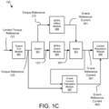
- FIG. 1C is a schematic drawing of an MTPA optimization 190.
- the MTPA operation 190 generates the D-axis reference current 361 and Q-axis reference current 363 for a current regulation module 305 based on the limited torque reference 121.
- the MTPA operation 190 may be performed by a torque trim module 301, an MTPA online module 303, and a Q-axis current calculation module 307, an MTPA offline module 309, and switches 311.
- the torque trim module 301, MTPA online module 303, Q-axis current calculation module 307, current regulation module 305, MTPA offline module 309, and switches 311 are implemented as hardware, software, or combinations thereof.
- the torque trim module 301, MTPA online module 303, Q-axis current calculation module 307, current regulation module 305, MTPA offline module 309, and switches 311 may be embodied in the controller 150.
- An MTPA offline process and an MTPA online process are both used to determine D-axis reference current 361 and the Q-axis reference current 363 11for a specific torque reference 123.
- the switches 311 select between employing the MTPA offline module 309 and the MTPA offline process and the MTPA online module 303 and the MTPA online process.
- the MTPA offline module 309 is employed in the offline MTPA process such as an autotune operation, which is using the offline calculated MTPA curve to generate the D-axis reference current 361.
- the MTPA online module 303 is employed in the online MTPA process.
- the torque trim module 301 receives the limited torque reference 121 and generates a torque reference 123.
- the MTPA offline module 309 generates the D-axis reference current 361 and the Q-axis reference current 363 based on the offline MTPA curve which is generated from an autotune operation as will be described hereafter.
- the MTPA curve from the MTPA offline process is used to estimate a D-axis reference current 361 for the MTPA online process.
- the D-axis reference current 361 is further iteratively modified within a search zone
- the Q-axis current calculation module 307 employs the torque reference 123 and the modified D-axis reference current 361 to modify a Q-axis reference current 363 to output the given torque specified by the limited torque reference 121.
- the current regulation module 305 regulates the Q-axis current 111 and a D-axis current 113 for the given torque based on the modified D-axis reference current 361 and the modified Q-axis reference current 363 to generate the gate signals 169 and improve the efficiency of the motor 101 as will be described hereafter.
- Figure 2A is a graph of D-axis flux 140 captured in an autotune test.
- the D-axis flux 131, Q-axis flux 133, and Q-axis flux at D-axis current equals 100 percent 135 captured during the autotune test are shown.
- the D-axis flux 131 includes at least three critical D-axis flux points 139.
- the critical D-axis flux points 139 are used to generate D-axis flux 131 for Q-axis currents 111 of zero, 100 percent, and 200 percent to generate the offline MTPA curve as will be shown in Figure 2B .
- Figure 2B is a graph of D-axis flux 140 for Q-axis currents 111 of zero 131a, 100 percent 131b, and 200 percent 131c after interpolation and extrapolation of the D-axis flux 131 using the critical D-axis flux points 139.
- Figure 2C is a graph of Q-axis flux 142 for D-axis currents 113 zero 133a, 100 percent 133b, and 200 percent 133c after interpolation and extrapolation of the Q-axis flux 133 using the D-axis flux 131 of Figure 2B .
- Figure 2D is a three-dimensional graph 250 of torque 375 estimated for Q-axis current 111 and D-axis current 113 based on the D-axis flux ⁇ d 131 and Q-axis flux ⁇ q 133 of Figures 2B-C .
- the torque 375 is calculated as a function of the Q-axis current 111 and D-axis current 113.
- a search algorithm is applied to the graph 250 and/or the function of Equation 1 to identify the MTPA curve 251.
- the MTPA curve 251 may represent an estimated minimum current amplitude 109 for a given torque 375.
- the MTPA curve 251 from the autotune test was used to control the motor 101. The embodiments improve the MTPA curve 251 as will be described hereafter.
- Figure 2E is a graph 253 of torque 375 estimated for Q-axis currents 111 and D-axis currents 113.
- torque 375 is calculated for a plurality of D-axis currents 113 and Q-axis currents 111.
- the torque 375 may be calculated using Equation 1.
- the search algorithm may identify the minimum current amplitude 109 for each torque 375 as the MTPA curve 251.
- Figure 3A is a graph of MTPA curve improvement or optimization.
- a curve of a given current amplitude 109 is shown as a function of a plurality of D-axis currents 113 and Q-axis currents 111.
- the current amplitude curve includes an initial torque point 373a
- Each torque point 373 comprises a torque 375, a Q-axis current 111, and aD-axis current 113.
- the initial torque point 373a is determined from the MTPA curve 251 for a given torque 375.
- the embodiments may improve and/or optimize the MTPA curve 251 by generating a search zone 379 for the MTPA curve 251.
- the search zone 379 may be for a given torque point 373.
- the search zone 379 may be for a given torque 375.
- the search zone 379 may comprise an upper D-axis reference current 367 and a lower D-axis reference current 369 for the given torque point 373 and/or given torque 375.
- the upper D-axis reference current 367 and the lower D-axis reference current 369 may represent current limits beyond which a D-axis reference current 361 is not modified.
- the D-axis reference current 361 may be the D-axis current 113 as used to test improvements to the MTPA curve 251.
- the Q-axis reference current 363 may be the Q-axis current 111 as used to test improvements to test improvements to the MTPA curve 251.
- the upper D-axis reference current 367 may be a first current limit and the lower D-axis reference current 369 may be a second current limit.
- the lower D-axis reference current 369 may be a first current limit and the upper D-axis reference current 367 may be a second current limit.
- the D-axis reference current 361 may be iteratively modified by iteratively adding 391 a D-axis reference current step to an initial D-axis reference current 361i until the D-axis reference current 361 equals and/or exceeds a first current limit such as the upper D-axis reference current 367.
- the D-axis reference current 361 may be iteratively modified 393 by iteratively subtracting the D-axis reference current step from the D-axis reference current 361 until the D-axis reference current 361 equals and/or exceeds a second current limit such as the lower D-axis reference current 369.
- the D-axis reference current 361 may be further iteratively modified 395 by iteratively adding the D-axis reference current step to the D-axis reference current 361 until the D-axis reference current 361 equals and/or exceeds the initial D-axis reference current 361i.
- the initial D-axis reference current 361i is equal to the D-axis current 113 for the given torque point 373 such as the torque point 373 for the MTPA curve 251.
- the initial D-axis reference current 361i is set equal to the second current limit and the D-axis reference current 361 is iteratively modified by iteratively adding the D-axis reference current step to the initial D-axis reference current 361i until the D-axis reference current 361 exceeds the first current limit.
- the D-axis reference current step may be in the range of 5 percent to 20 percent of the search zone 379. For example, if the search zone 379 is 0.2 amps, the D-axis reference current step may be in the range of 0.01 amps to 0.04 amps. The D-axis reference current step may be negative
- the D-axis reference current step is 20 percent of the search zone 379.
- the D-axis reference current 361 may be iteratively modified to the lower D-axis reference 369 plus one times the D-axis reference current step, two times the D-axis reference current step, and three times the D-axis reference current step.
- a new upper D-axis reference current 367 and lower D-axis reference 369 may be iteratively set to the modified D-axis reference current 361 and the modified Q-axis reference current 363 with a lowest current amplitude 109 plus and minus the D-axis reference current step respectively.
- the D-axis reference current 361 may be again iteratively modified using the new upper D-axis reference current 367 and new lower D-axis reference current 369. In one embodiment, 2-4 iterations of upper D-axis reference current 367 and lower D-axis reference current 369 are tested.
- FIG. 3B is a schematic block diagram of MTPA data 360
- the MTPA data 360 may be used to improve the MTPA curve 251.
- the MTPA data 360 may be organized as a data structure in a memory.
- the MTPA data 360 includes the D-axis reference current 361, the Q-axis reference current 363, the D-axis reference current step 365, the upper D-axis reference current 367, the lower D-axis reference current 369, a plurality of torque points 373, the search algorithm 378, and the autotune test 381.
- the upper D-axis reference current 367 and the lower D-axis reference current 369 may comprise the current limits 371.
- FIG 3C is a schematic block diagram of the torque point 373 of Figure 3B .
- the torque point 373 comprises of torque 375 and a current pair 377.
- the current pair 377 comprises a Q-axis current 111 and a D-axis current 113.
- the torque point 373 includes a current amplitude 109 corresponding to the Q-axis current 111 and the D-axis current 113.
- FIG 4 is a schematic block diagram of the controller 150.
- the controller 150 may be a computer.
- the controller 150 includes a processor 405, a memory 410, and communication hardware 415.
- the memory 410 may store code and data.
- the processor 405 may execute the code and process the data.
- the communication hardware 415 may communicate with other devices such as the inverter 165 via the gate signals 169, the limited torque reference 121, and the like.
- FIGS 5A-C are a schematic flow chart diagram of an MTPA update and/or optimization method 500.
- the MTPA update method 500 may generate an offline MTPA curve 251 and update at least one torque point 373 for the MTPA curve 251.
- the method 500 may be performed by the controller 150.
- the method 500 starts, and in one embodiment, the controller 150 performs 501 the autotune test 381 on the motor 101.
- the autotune test 381 may calculate the D-axis flux 131 and the Q-axis flux 133 as shown in Figure 2A .
- the controller 150 may further select 503 at least three critical D-axis flux points 139 in a knee portion on D-axis flux curve 131 as shown in Figure 2A . in addition, the controller 150 may generate 504 the D-axis flux 131 and the Q-axis flux 133 such as is shown in Figures 2B and 2C respectively.
- the controller 150 may calculate 505 the torques 375 for a plurality of torque points 373 as a function of the corresponding D-axis currents 113 and Q-axis currents 111.
- the torques 375 may be calculated using Equation 1.
- the controller 150 may estimate 507 the initial MTPA curve 251.
- the initial MTPA curve 251 may be estimated 507 based on the plurality of torque points 373.
- the controller 105 calculates the plurality of torque points 373 as illustrated in Figure 2D and employs the search algorithm 378 to identify the minimum current amplitude 109 for each given torque 375 as the initial MTPA curve 251 as shown in Figure 2E .
- the controller 150 selects 509 a given torque point 373 on the MTPA curve 251.
- the given torque point 373 may be selected 509 to be updated.
- the method 500 may select 509 at least two torque points 373 to be updated. In a certain embodiment, the method selects 509 each torque point 373 to be updated.
- the controller generates 511 a search zone 379 for the MTPA curve 251 for the given torque point 373
- the search zone 379 comprises an upper D-axis reference current 367 and a lower D-axis reference current 369 for the given torque point 373.
- the controller may generate 511 a D-axis reference current 361 or an initial D-axis reference current 361i such as is shown in Figure 3A .
- the controller 150 determines 513 whether an angular velocity of the motor 101 is stable.
- the angular velocity may be stable if the angular velocity does not vary by more than 2 percent. If the angular velocity is not stable, the method 500 ends. If the angular velocity is stable, the controller 150 determines 515 whether the torque reference 123 is stable.
- the torque reference 123 may be stable if the torque reference 123 does not vary by more than 2 percent. If the torque reference 123 is not stable, the method 500 ends.
- the controller 150 captures the current amplitude 109 for the D-axis reference current 361.
- the controller 150 further iteratively modifies 519 the D-axis reference current 361 between the upper D-axis reference current 367 and the lower D-axis reference current 369 of the search zone 379.
- the controller 150 may modify 519 the D-axis reference current 361 by adding and/or subtracting the D-axis reference current step 365.
- the controller 150 modifies 521 the Q-axis reference current 363 to output the given torque 375 of the torque point 373 and captures 523 the current amplitude 109.
- the controller 150 iteratively modifies the D-axis reference current 361 until the determining 525 that iterations are complete. Iterations may be complete when a specified number of D-axis reference currents 361 are tested at least once.
- the controller 150 updates 527 the corresponding current pair 377 of the given torque point 373 to the modified D-axis reference current 361 and modified Q-axis reference current 363 with a lowest current amplitude 109.
- the Q-axis current 111 of the torque point 373 is set to the modified Q-axis reference current 363 with the lowest current amplitude 109 and the D-axis current 113 of the torque point 373 is set to the corresponding modified D-axis reference current 361.
- the MTPA curve 251 is updated, improving the efficiency of the motor 101.
- the controller 150 determines 529 if the update to the MTPA curve 251 is complete.
- the update may be complete if all desired torque points 373 are updated. If the update is not complete, the controller 150 selects 509 a new given torque point 373. If the update is complete, the method 500 ends.
- Figure 6A are graphs 601 illustrating the MTPA searching and/or optimization method 500.
- the D-axis reference current 361 for a given torque point 373 is set to an initial D-axis reference current 361i at time zero.
- the D-axis reference current 361 is iteratively modified by adding the D-axis reference current step 365 until the D-axis reference current 361 is equal to the upper D-axis reference current 367.
- the D-axis reference current 361 is further iteratively modified by subtracting the D-axis reference current step 365 until the D-axis reference current 361 is equal to the lower D-axis reference current 369.
- the D-axis reference current 361 is iteratively modified by adding the D-axis reference current step 365 until the D-axis reference current 361 is equal to the initial D-axis reference current 361i.
- the Q-axis reference current 363 is modified to output the given torque 375 for the torque point 373.
- the current amplitude 309 is captured for each modified D-axis reference current 361 and modified Q-axis reference current 363 current pair 377.
- the current pair 377 with the lowest current amplitude 109 is used to update the MTPA curve 251 at the given torque point 373.
- Figure 6B are graphs 603 illustrating the MTPA searching and/or optimization method 500.
- the D-axis reference current 361 for a given torque 375 is set to an initial D-axis reference current 361i at an initial time.
- the D-axis reference current 361 is iteratively modified by adding the D-axis reference current step 365 until the D-axis reference current 361 is equal to the upper D-axis reference current 367.
- the D-axis reference current 361 is further iteratively modified by subtracting the D-axis reference current step 365 until the D-axis reference current 361 is equal to the lower D-axis reference current 369.
- the D-axis reference current 361 is iteratively modified by adding the D-axis reference current step 365 until the D-axis reference current 361 is equal to the initial D-axis reference current 361i.
- the Q-axis reference current 363 is modified to output the given torque 375.
- the current amplitude 309 is captured for each modified D-axis reference current 361 and modified Q-axis reference current 363 current pair 377.
- the current pair 377 with lowest current amplitude 109 is used to update the MTPA curve 251 for the given torque 375.
- Figure 6C is a graph of the D-axis reference current 361 and Q-axis reference current 363 for the MTPA searching and/or optimization method 500
- the current amplitude 109 is captured for a plurality of modified D-axis reference current 361 and corresponding modified Q-axis reference current 363 current pairs 377 within a search zone 379.
- a minimum current amplitude curve 605 is shown.
- Figure 6D is a closeup graph of the D-axis reference current 361 and Q-axis reference current 363 for the MTPA searching and/or optimization method 500 of Figure 6C .
- the current pair 373a with the minimum current amplitude 109 is selected to update the MTPA curve 251
- the MTPA curve 251 is updated with the modified D-axis reference current 361 and the modified Q-axis reference current 363 of the indicated current pair 377a.
- offline MTPA curves 251 have been generated to provide input in controlling motors 101.
- the offline MTPA curves 251 are often generated by an autotune test 381.
- the offline MTPA curves 251 often have inaccuracies that result in less efficient motor operation.
- the embodiments generate the offline MTPA curve 251 with a plurality of torque points 373.
- the embodiments further update the current pairs 377 of the MTPA curve 251 with a modified D-axis reference current 361 and a modified Q-axis reference current 363 within a search zone 379.
- the embodiments select the current pair 377 with the lowest current amplitude 109 to update the MTPA curve 251.
- the MTPA curve 251 more accurately reflects the operation of the motor 101, allowing the controller 150 to more efficiently operate the motor 101.
Abstract
For improving Maximum Torque per Amps (MTPA) control, a method generates an offline MTPA curve based on an autotune test for a motor, which is used as offline MTPA control in order to run a motor at a high efficiency operation point. Another online method generates a search zone for the MTPA curve for a given torque point. The search zone includes an upper D-axis reference current and a lower D-axis reference current for the given torque point. The method iteratively modifies a D-axis reference current between the upper D-axis reference current and the lower D-axis reference current of the search zone. The method modifies a Q-axis reference current to output the given torque. The method updates a corresponding current pair of the given torque point to the modified D-axis reference current and the modified Q-axis reference current with a lowest current amplitude to improve MTPA control of the motor.
Description
- The subject matter disclosed herein relates to improving and/or optimizing Maximum Torque per Amps (MTPA) control.
- A method for improving MTPA controls disclosed. The method generates an offline MTPA curve based on an autotune test for a motor. The method generates a search zone for the MTPA curve for a given torque point. The search zone includes an upper D-axis reference current and a lower D-axis reference current for the given torque point. The MTPA curve comprises torque points of torques for current pairs of a Q-axis current and a D-axis current for the motor. The method iteratively modifies a D-axis reference current between the upper D-axis reference current and the lower D-axis reference current of the search zone. The method modifies a Q-axis reference current to output the given torque. The method updates a corresponding current pair of the given torque point to the modified D-axis reference current and the modified Q-axis reference current with a lowest current amplitude to further improve the efficiency of the motor.
- An apparatus for improving MTPA control is disclosed. The apparatus includes a controller. The controller generates an offline MTPA curve based on an autotune test for a motor. The controller generates a search zone for the MTPA curve for a given torque point. The search zone includes an upper D-axis reference current and a lower D-axis reference current for the given torque point. The MTPA curve comprises torque points of torques for current pairs of a Q-axis current and a D-axis current for the motor. The controller iteratively modifies a D-axis reference current between the upper D-axis reference current and the lower D-axis reference current of the search zone. The controller modifies a Q-axis reference current to output the given torque. The controller updates the corresponding current pair of the given torque point to the modified D-axis reference current and the modified Q-axis reference current with a lowest current amplitude to further improve the efficiency of the motor.
- A system for improving MTPA controls disclosed. The system includes a motor and a motor drive. The motor drive generates an offline MTPA curve based on an autotune test for a motor. The motor drive generates a search zone for the MTPA curve for a given torque point. The search zone includes an upper D-axis reference current and a lower D-axis reference current for the given torque point. The MTPA curve comprises torque points of torques for current pairs of a Q-axis current and a D-axis current for the motor. The motor drive iteratively modifies a D-axis reference current between the upper D-axis reference current and the lower D-axis reference current of the search zone. The motor drive modifies a Q-axis reference current to output the given torque The motor drive updates the corresponding current pair of the given torque point to the modified D-axis reference current and the modified Q-axis reference current with a lowest current amplitude to further improve the efficiency of the motor.
- In order that the advantages of the embodiments of the invention will be readily understood, a more particular description of the embodiments briefly described above will be rendered by reference to specific embodiments that are illustrated in the appended drawings. Understanding that these drawings depict only some embodiments and are not therefore to be considered to be limiting of scope, the embodiments will be described and explained with additional specificity and detail through the use of the accompanying drawings, in which:
-
Figure 1A is a schematic diagram of motor system according to an embodiment; -
Figure 1B is a drawing direct axis currents and quadrature axis currents according to an embodiment; -
Figure 1C is a schematic drawing of MTPA optimization according to an embodiment, -
Figure 2A is a graph of direct axis flux points captured in an autotune test according to an embodiment; -
Figure 2B is a graph of direct axis flux points after interpolation and extrapolation according to an embodiment, -
Figure 2C is a graph of quadrature axis flux points after interpolation and extrapolation according to an embodiment; -
Figure 2D is a three-dimensional graph of torque estimated for quadrature axis current and direct axis current according to an embodiment; -
Figure 2E is a graph of torque estimated for quadrature axis current and direct axis current according to an embodiment; -
Figure 3A is a graph of MTPA improvement or optimization according to an embodiment; -
Figure 3B is a schematic block diagram of MTPA data according to an embodiment; -
Figure 3C is a schematic block diagram of a torque point according to an embodiment; -
Figure 4 is a schematic block diagram of a controller according to an embodiment; -
Figures 5A-C are schematic flow chart diagram of an MTPA update and/or optimization method according to an embodiment; -
Figure 6A are graphs of an online MTPA searching method according to an embodiment; -
Figure 6B are graphs of an online MTPA searching method according to an embodiment; -
Figure 6C is a graph of the direct axis reference current and quadrature axis reference current for an MTPA searching method according to an embodiment; and -
Figure 6D is a graph of the direct axis reference current and quadrature axis reference current for an MTPA searching method according to an embodiment. - Reference throughout this specification to "one embodiment," "an embodiment," or similar language means that a particular feature, structure, or characteristic described in connection with the embodiment is included in at least one embodiment. Thus, appearances of the phrases "in one embodiment," "in an embodiment," and similar language throughout this specification may, but do not necessarily, all refer to the same embodiment, but mean "one or more but not all embodiments" unless expressly specified otherwise. The terms "including," "comprising," "having," and variations thereof mean "including but not limited to" unless expressly specified otherwise. An enumerated listing of items does not imply that any or all of the items are mutually exclusive and/or mutually inclusive, unless expressly specified otherwise. The terms "a," "an," and "the" also refer to "one or more" unless expressly specified otherwise. The term "and/or" indicates embodiments of one or more of the listed elements, with "A and/or B" indicating embodiments of element A alone, element B alone, or elements A and B taken together.
- Furthermore, the described features, advantages, and characteristics of the embodiments may be combined in any suitable manner. One skilled in the relevant art will recognize that the embodiments may be practiced without one or more of the specific features or advantages of a particular embodiment. In other instances, additional features and advantages may be recognized in certain embodiments that may not be present in all embodiments.
- These features and advantages of the embodiments will become more fully apparent from the following description and appended claims or may be learned by the practice of embodiments as set forth hereinafter As will be appreciated by one skilled in the art, aspects of the present invention may be embodied as a system, method, and/or computer program product. Accordingly, aspects of the present invention may take the form of an entirely hardware embodiment, an entirely software embodiment (including firmware, resident software, micro-code, etc.) or an embodiment combining software and hardware aspects that may all generally be referred to herein as a "circuit," "module," or "system " Furthermore, aspects of the present invention may take the form of a computer program product embodied in one or more computer readable medium(s) having program code embodied thereon.
- The computer readable medium may be a tangible computer readable storage medium storing the program code. The computer readable storage medium may be, for example, but not limited to, an electronic, magnetic, optical, electromagnetic, infrared, holographic, micromechanical, or semiconductor system, apparatus, or device, or any suitable combination of the foregoing.
- More specific examples of the computer readable storage medium may include but are not limited to a portable computer diskette, a hard disk, a random access memory (RAM), a read-only memory (ROM), an erasable programmable read-only memory (EPROM or Flash memory), a portable compact disc read-only memory (CD-ROM), a digital versatile disc (DVD), an optical storage device, a magnetic storage device, a holographic storage medium, a micromechanical storage device, or any suitable combination of the foregoing. In the context of this document, a computer readable storage medium may be any tangible medium that can contain, and/or store program code for use by and/or in connection with an instruction execution system, apparatus, or device.
- Program code for carrying out operations for aspects of the present invention may be written in any combination of one or more programming languages, including an object-oriented programming language such as Python, Ruby, R, Java, Java Script, Smalltalk, C++, C sharp, Lisp, Clojure, PHP or the like and conventional procedural programming languages, such as the "C" programming language or similar programming languages. The program code may execute entirely on the user's computer, partly on the user's computer, as a stand-alone software package, partly on the user's computer and partly on a remote computer or entirely on the remote computer or server. In the latter scenario, the remote computer may be connected to the user's computer through any type of network, including a local area network (LAN) or a wide area network (WAN), or the connection may be made to an external computer (for example, through the Internet using an Internet Service Provider). The computer program product may be shared, simultaneously serving multiple customers in a flexible, automated fashion.
- The schematic flowchart diagrams and/or schematic block diagrams in the Figures illustrate the architecture, functionality, and operation of possible implementations. It should also be noted that, in some alternative implementations, the functions noted in the block may occur out of the order noted in the Figures. For example, two blocks shown in succession may, in fact, be executed substantially concurrently, or the blocks may sometimes be executed in the reverse order, depending upon the functionality involved. Although various arrow types and line types may be employed in the flowchart and/or block diagrams, they are understood not to limit the scope of the corresponding embodiments Indeed, some arrows or other connectors may be used to indicate only an exemplary logical flow of the depicted embodiment.
- The description of elements in each figure may refer to elements of proceeding figures. Like numbers refer to like elements in all figures, including alternate embodiments of like elements,
-
Figure 1A is a schematic diagram of amotor system 100. Thesystem 100 includes amotor 101 and amotor drive 161 Themotor 101 may be a salient motor, a synchronous reluctance motor, a synchronous machine, a permanent magnet motor, and the like. Themotor 101 is controlled by themotor drive 161. - In the depicted embodiment, the
motor 101 includes arotor 105 and a plurality ofcoils 103a-c. Themotor drive 161 may direct electric currents with anoutput voltage 115 through thecoils 103a-c to generate a motor flux that drives therotor 105. - The
motor drive 161 may control themotor 101 to generate a specified torque at a specified angular velocity in response to alimited torque reference 121. Thelimited torque reference 121 may specify the torque for themotor 101 and/or the angular velocity for themotor 101. Themotor drive 161 may be required to control themotor 101 within a range of torques and/or angular velocities for a variety of loads base on thelimited torque reference 121. - In the depicted embodiment, the
motor drive 161 includes a rectifier and/orconverter 163, referred to hereafter as arectifier 163, aninverter 165, abus capacitor 166, and acontroller 150. Theconverter 163 supplies a Direct Current (DC)bus voltage 117 and a neutral 118 to theinverter 165. Acapacitor 166 may filter theDC bus voltage 117. Thecontroller 150 may include a processor as shown inFigure 4 . Thecontroller 150 may produce the gate signals 169 to control theoutput voltage 115 supplied by theinverter 165, and therefore control themotor 101. Thesystem 100 may include anencoder 139 that generates aposition signal 102. Theposition signal 102 may be used accurately control themotor 101. In a certain embodiment, at least a portion of themotor drive 161 comprises one or more of hardware and executable code, the executable code stored on one or more computer readable storage media. -
Figure 1B is a drawing of direct axis (D-axis) currents Id 113 and quadrature axis (Q-axis) currents Iq 111 that are supplied to themotor 101 by theinverter 165. The D-axis current 113 generates flux along a field winding or D-axis 117 for themotor 101. The Q-axis current 111 generates torque along a torque or Q-axis 115. The combined D-axis current 113 and the Q-axis current 111 have acurrent amplitude 109. - An autotune test may be performed for the
motor 101. The autotune test may be a default operation. The autotune test may be performed at a startup of themotor 101. The autotune process may generate an offline MPTA curve that is used to select the Q-axis current 111 and D-axis current 113 for a given torque that minimizes thecurrent amplitude 109. The offline MTPA curve is shown in more detail inFigures 2D-E . - Unfortunately, the offline MTPA curve generated during the autotune test may include inaccuracies. As a result, the Q-axis current 111 and D-axis current 113 selections are less than optimal and the efficiency of the
motor 101 is decreased. The embodiments improve the MTPA curve estimates as will be described hereafter. As a result, the efficiency of themotor 101 is improved. -
Figure 1C is a schematic drawing of anMTPA optimization 190. TheMTPA operation 190 generates the D-axis reference current 361 and Q-axis reference current 363 for acurrent regulation module 305 based on thelimited torque reference 121. TheMTPA operation 190 may be performed by atorque trim module 301, an MTPAonline module 303, and a Q-axis current calculation module 307, an MTPAoffline module 309, and switches 311. Thetorque trim module 301, MTPAonline module 303, Q-axis current calculation module 307,current regulation module 305, MTPAoffline module 309, and switches 311 are implemented as hardware, software, or combinations thereof. Thetorque trim module 301, MTPAonline module 303, Q-axis current calculation module 307,current regulation module 305, MTPAoffline module 309, and switches 311 may be embodied in thecontroller 150. - An MTPA offline process and an MTPA online process are both used to determine D-axis reference current 361 and the Q-axis reference current 363 11for a
specific torque reference 123. Theswitches 311 select between employing the MTPAoffline module 309 and the MTPA offline process and the MTPAonline module 303 and the MTPA online process. The MTPAoffline module 309 is employed in the offline MTPA process such as an autotune operation, which is using the offline calculated MTPA curve to generate the D-axis reference current 361. The MTPAonline module 303 is employed in the online MTPA process. - In both the MTPA offline process and the MTPA online process, the
torque trim module 301 receives thelimited torque reference 121 and generates atorque reference 123. The MTPAoffline module 309 generates the D-axis reference current 361 and the Q-axis reference current 363 based on the offline MTPA curve which is generated from an autotune operation as will be described hereafter. - The MTPA curve from the MTPA offline process is used to estimate a D-axis reference current 361 for the MTPA online process. The D-axis reference current 361 is further iteratively modified within a search zone The Q-axis current calculation module 307 employs the
torque reference 123 and the modified D-axis reference current 361 to modify a Q-axis reference current 363 to output the given torque specified by thelimited torque reference 121. - The
current regulation module 305 regulates the Q-axis current 111 and a D-axis current 113 for the given torque based on the modified D-axis reference current 361 and the modified Q-axis reference current 363 to generate the gate signals 169 and improve the efficiency of themotor 101 as will be described hereafter. -
Figure 2A is a graph of D-axis flux 140 captured in an autotune test. The D-axis flux 131, Q-axis flux 133, and Q-axis flux at D-axis current equals 100percent 135 captured during the autotune test are shown. The D-axis flux 131 includes at least three critical D-axis flux points 139. The critical D-axis flux points 139 are used to generate D-axis flux 131 for Q-axis currents 111 of zero, 100 percent, and 200 percent to generate the offline MTPA curve as will be shown inFigure 2B . -
Figure 2B is a graph of D-axis flux 140 for Q-axis currents 111 of zero 131a, 100percent 131b, and 200percent 131c after interpolation and extrapolation of the D-axis flux 131 using the critical D-axis flux points 139. -
Figure 2C is a graph of Q-axis flux 142 for D-axis currents 113 zero 133a, 100percent 133b, and 200percent 133c after interpolation and extrapolation of the Q-axis flux 133 using the D-axis flux 131 ofFigure 2B . -
Figure 2D is a three-dimensional graph 250 oftorque 375 estimated for Q-axis current 111 and D-axis current 113 based on the D-axis flux ϕ d 131 and Q-axis flux ϕ q 133 ofFigures 2B-C . Thetorque 375 is calculated as a function of the Q-axis current 111 and D-axis current 113. In one embodiment, thetorque Trq 375 is calculated usingEquation 1.

- In one embodiment, a search algorithm is applied to the
graph 250 and/or the function ofEquation 1 to identify theMTPA curve 251. TheMTPA curve 251 may represent an estimated minimumcurrent amplitude 109 for a giventorque 375. In the past, theMTPA curve 251 from the autotune test was used to control themotor 101. The embodiments improve theMTPA curve 251 as will be described hereafter. -
Figure 2E is agraph 253 oftorque 375 estimated for Q-axis currents 111 and D-axis currents 113. In one embodiment,torque 375 is calculated for a plurality of D-axis currents 113 and Q-axis currents 111. Thetorque 375 may be calculated usingEquation 1. The search algorithm may identify the minimumcurrent amplitude 109 for eachtorque 375 as theMTPA curve 251. -
Figure 3A is a graph of MTPA curve improvement or optimization. In the depicted embodiment, a curve of a givencurrent amplitude 109 is shown as a function of a plurality of D-axis currents 113 and Q-axis currents 111. The current amplitude curve includes aninitial torque point 373a Eachtorque point 373 comprises atorque 375, a Q-axis current 111, and aD-axis current 113. Theinitial torque point 373a is determined from theMTPA curve 251 for a giventorque 375. - The embodiments may improve and/or optimize the
MTPA curve 251 by generating asearch zone 379 for theMTPA curve 251. Thesearch zone 379 may be for a giventorque point 373. Thesearch zone 379 may be for a giventorque 375. Thesearch zone 379 may comprise an upper D-axis reference current 367 and a lower D-axis reference current 369 for the giventorque point 373 and/or giventorque 375. The upper D-axis reference current 367 and the lower D-axis reference current 369 may represent current limits beyond which a D-axis reference current 361 is not modified. The D-axis reference current 361 may be the D-axis current 113 as used to test improvements to theMTPA curve 251. The Q-axis reference current 363 may be the Q-axis current 111 as used to test improvements to test improvements to theMTPA curve 251. - . The upper D-axis reference current 367 may be a first current limit and the lower D-axis reference current 369 may be a second current limit. Alternatively, the lower D-axis reference current 369 may be a first current limit and the upper D-axis reference current 367 may be a second current limit.
- The D-axis reference current 361 may be iteratively modified by iteratively adding 391 a D-axis reference current step to an initial D-axis reference current 361i until the D-axis reference current 361 equals and/or exceeds a first current limit such as the upper D-axis reference current 367. In addition, the D-axis reference current 361 may be iteratively modified 393 by iteratively subtracting the D-axis reference current step from the D-axis reference current 361 until the D-axis reference current 361 equals and/or exceeds a second current limit such as the lower D-axis reference current 369. The D-axis reference current 361 may be further iteratively modified 395 by iteratively adding the D-axis reference current step to the D-axis reference current 361 until the D-axis reference current 361 equals and/or exceeds the initial D-axis reference current 361i.
- In one embodiment, the initial D-axis reference current 361i is equal to the D-axis current 113 for the given
torque point 373 such as thetorque point 373 for theMTPA curve 251. In an alternative embodiment, the initial D-axis reference current 361i is set equal to the second current limit and the D-axis reference current 361 is iteratively modified by iteratively adding the D-axis reference current step to the initial D-axis reference current 361i until the D-axis reference current 361 exceeds the first current limit. - The D-axis reference current step may be in the range of 5 percent to 20 percent of the
search zone 379. For example, if thesearch zone 379 is 0.2 amps, the D-axis reference current step may be in the range of 0.01 amps to 0.04 amps. The D-axis reference current step may be negative - In a certain embodiment, the D-axis reference current step is 20 percent of the
search zone 379. The D-axis reference current 361 may be iteratively modified to the lower D-axis reference 369 plus one times the D-axis reference current step, two times the D-axis reference current step, and three times the D-axis reference current step. A new upper D-axis reference current 367 and lower D-axis reference 369 may be iteratively set to the modified D-axis reference current 361 and the modified Q-axis reference current 363 with a lowestcurrent amplitude 109 plus and minus the D-axis reference current step respectively. The D-axis reference current 361 may be again iteratively modified using the new upper D-axis reference current 367 and new lower D-axis reference current 369. In one embodiment, 2-4 iterations of upper D-axis reference current 367 and lower D-axis reference current 369 are tested. -
Figure 3B is a schematic block diagram ofMTPA data 360 TheMTPA data 360 may be used to improve theMTPA curve 251. TheMTPA data 360 may be organized as a data structure in a memory. In the depicted embodiment, theMTPA data 360 includes the D-axis reference current 361, the Q-axis reference current 363, the D-axis referencecurrent step 365, the upper D-axis reference current 367, the lower D-axis reference current 369, a plurality oftorque points 373, thesearch algorithm 378, and theautotune test 381. The upper D-axis reference current 367 and the lower D-axis reference current 369 may comprise the current limits 371. -
Figure 3C is a schematic block diagram of thetorque point 373 ofFigure 3B . In the depicted embodiment, thetorque point 373 comprises oftorque 375 and acurrent pair 377. Thecurrent pair 377 comprises a Q-axis current 111 and a D-axis current 113. In one embodiment, thetorque point 373 includes acurrent amplitude 109 corresponding to the Q-axis current 111 and the D-axis current 113. -
Figure 4 is a schematic block diagram of thecontroller 150. Thecontroller 150 may be a computer. In the depicted embodiment, thecontroller 150 includes aprocessor 405, amemory 410, andcommunication hardware 415. Thememory 410 may store code and data. Theprocessor 405 may execute the code and process the data. Thecommunication hardware 415 may communicate with other devices such as theinverter 165 via the gate signals 169, thelimited torque reference 121, and the like. -
Figures 5A-C are a schematic flow chart diagram of an MTPA update and/oroptimization method 500. TheMTPA update method 500 may generate anoffline MTPA curve 251 and update at least onetorque point 373 for theMTPA curve 251. Themethod 500 may be performed by thecontroller 150. - The
method 500 starts, and in one embodiment, thecontroller 150 performs 501 theautotune test 381 on themotor 101. Theautotune test 381 may calculate the D-axis flux 131 and the Q-axis flux 133 as shown inFigure 2A . - The
controller 150 may further select 503 at least three critical D-axis flux points 139 in a knee portion on D-axis flux curve 131 as shown inFigure 2A . in addition, thecontroller 150 may generate 504 the D-axis flux 131 and the Q-axis flux 133 such as is shown inFigures 2B and2C respectively. - The
controller 150 may calculate 505 thetorques 375 for a plurality oftorque points 373 as a function of the corresponding D-axis currents 113 and Q-axis currents 111. Thetorques 375 may be calculated usingEquation 1. Thecontroller 150 may estimate 507 theinitial MTPA curve 251. Theinitial MTPA curve 251 may be estimated 507 based on the plurality of torque points 373. In one embodiment, thecontroller 105 calculates the plurality oftorque points 373 as illustrated inFigure 2D and employs thesearch algorithm 378 to identify the minimumcurrent amplitude 109 for each giventorque 375 as theinitial MTPA curve 251 as shown inFigure 2E . - In one embodiment, the
controller 150 selects 509 a giventorque point 373 on theMTPA curve 251. The giventorque point 373 may be selected 509 to be updated. Themethod 500 may select 509 at least twotorque points 373 to be updated. In a certain embodiment, the method selects 509 eachtorque point 373 to be updated. - The controller generates 511 a
search zone 379 for theMTPA curve 251 for the giventorque point 373 Thesearch zone 379 comprises an upper D-axis reference current 367 and a lower D-axis reference current 369 for the giventorque point 373. In addition, the controller may generate 511 a D-axis reference current 361 or an initial D-axis reference current 361i such as is shown inFigure 3A . - In one embodiment, the
controller 150 determines 513 whether an angular velocity of themotor 101 is stable. The angular velocity may be stable if the angular velocity does not vary by more than 2 percent. If the angular velocity is not stable, themethod 500 ends. If the angular velocity is stable, thecontroller 150 determines 515 whether thetorque reference 123 is stable. Thetorque reference 123 may be stable if thetorque reference 123 does not vary by more than 2 percent. If thetorque reference 123 is not stable, themethod 500 ends. - If the
torque reference 123 is stable, thecontroller 150 captures thecurrent amplitude 109 for the D-axis reference current 361. Thecontroller 150 further iteratively modifies 519 the D-axis reference current 361 between the upper D-axis reference current 367 and the lower D-axis reference current 369 of thesearch zone 379. For example, thecontroller 150 may modify 519 the D-axis reference current 361 by adding and/or subtracting the D-axis referencecurrent step 365. - The
controller 150 modifies 521 the Q-axis reference current 363 to output the giventorque 375 of thetorque point 373 and captures 523 thecurrent amplitude 109. Thecontroller 150 iteratively modifies the D-axis reference current 361 until the determining 525 that iterations are complete. Iterations may be complete when a specified number of D-axis reference currents 361 are tested at least once. - The
controller 150updates 527 the correspondingcurrent pair 377 of the giventorque point 373 to the modified D-axis reference current 361 and modified Q-axis reference current 363 with a lowestcurrent amplitude 109. For example, the Q-axis current 111 of thetorque point 373 is set to the modified Q-axis reference current 363 with the lowestcurrent amplitude 109 and the D-axis current 113 of thetorque point 373 is set to the corresponding modified D-axis reference current 361. As a result, theMTPA curve 251 is updated, improving the efficiency of themotor 101. - The
controller 150 determines 529 if the update to theMTPA curve 251 is complete. The update may be complete if all desiredtorque points 373 are updated. If the update is not complete, thecontroller 150 selects 509 a new giventorque point 373. If the update is complete, themethod 500 ends. -
Figure 6A aregraphs 601 illustrating the MTPA searching and/oroptimization method 500. In the depicted example, the D-axis reference current 361 for a giventorque point 373 is set to an initial D-axis reference current 361i at time zero. The D-axis reference current 361 is iteratively modified by adding the D-axis referencecurrent step 365 until the D-axis reference current 361 is equal to the upper D-axis reference current 367. The D-axis reference current 361 is further iteratively modified by subtracting the D-axis referencecurrent step 365 until the D-axis reference current 361 is equal to the lower D-axis reference current 369. The D-axis reference current 361 is iteratively modified by adding the D-axis referencecurrent step 365 until the D-axis reference current 361 is equal to the initial D-axis reference current 361i. - With each modification to the D-axis reference current 361, the Q-axis reference current 363 is modified to output the given
torque 375 for thetorque point 373. Thecurrent amplitude 309 is captured for each modified D-axis reference current 361 and modified Q-axis reference current 363current pair 377. Thecurrent pair 377 with the lowestcurrent amplitude 109 is used to update theMTPA curve 251 at the giventorque point 373. -
Figure 6B aregraphs 603 illustrating the MTPA searching and/oroptimization method 500. In the depicted example, the D-axis reference current 361 for a giventorque 375 is set to an initial D-axis reference current 361i at an initial time. The D-axis reference current 361 is iteratively modified by adding the D-axis referencecurrent step 365 until the D-axis reference current 361 is equal to the upper D-axis reference current 367. The D-axis reference current 361 is further iteratively modified by subtracting the D-axis referencecurrent step 365 until the D-axis reference current 361 is equal to the lower D-axis reference current 369. The D-axis reference current 361 is iteratively modified by adding the D-axis referencecurrent step 365 until the D-axis reference current 361 is equal to the initial D-axis reference current 361i. - With each modification to the D-axis reference current 361, the Q-axis reference current 363 is modified to output the given
torque 375. Thecurrent amplitude 309 is captured for each modified D-axis reference current 361 and modified Q-axis reference current 363current pair 377. Thecurrent pair 377 with lowestcurrent amplitude 109 is used to update theMTPA curve 251 for the giventorque 375. -
Figure 6C is a graph of the D-axis reference current 361 and Q-axis reference current 363 for the MTPA searching and/oroptimization method 500 In the depicted embodiment, thecurrent amplitude 109 is captured for a plurality of modified D-axis reference current 361 and corresponding modified Q-axis reference current 363current pairs 377 within asearch zone 379. A minimumcurrent amplitude curve 605 is shown. -
Figure 6D is a closeup graph of the D-axis reference current 361 and Q-axis reference current 363 for the MTPA searching and/oroptimization method 500 ofFigure 6C . In the depicted embodiment, thecurrent pair 373a with the minimumcurrent amplitude 109 is selected to update theMTPA curve 251 Thus, theMTPA curve 251 is updated with the modified D-axis reference current 361 and the modified Q-axis reference current 363 of the indicated current pair 377a. - In the past, offline MTPA curves 251 have been generated to provide input in controlling
motors 101. The offline MTPA curves 251 are often generated by anautotune test 381. Unfortunately, the offline MTPA curves 251 often have inaccuracies that result in less efficient motor operation. - The embodiments generate the
offline MTPA curve 251 with a plurality of torque points 373. The embodiments further update thecurrent pairs 377 of theMTPA curve 251 with a modified D-axis reference current 361 and a modified Q-axis reference current 363 within asearch zone 379. The embodiments select thecurrent pair 377 with the lowestcurrent amplitude 109 to update theMTPA curve 251. As a result, theMTPA curve 251 more accurately reflects the operation of themotor 101, allowing thecontroller 150 to more efficiently operate themotor 101. - This description uses examples to disclose the invention and also to enable any person skilled in the art to practice the invention, including making and using any devices or systems and performing any incorporated methods. The patentable scope of the invention is defined by the claims and may include other examples that occur to those skilled in the art. Such other examples are intended to be within the scope of the claims if they have structural elements that do not differ from the literal language of the claims, or if they include equivalent structural elements with insubstantial differences from the literal language of the claims.
Claims (15)
- A method comprising:generating an offline Maximum Torque Per Amps (MTPA) curve based on an autotune test for a motor;generating a search zone for the MTPA curve for a given torque point, the search zone comprising an upper D-axis reference current and a lower D-axis reference current for the given torque point, wherein the MTPA curve comprises torque points of torques for current pairs of a Q-axis current and a D-axis current for the motor;iteratively modifying a D-axis reference current between the upper D-axis reference current and the lower D-axis reference current of the search zone;modifying a Q-axis reference current to output the given torque; andupdating a corresponding current pair of the given torque point to the modified D-axis reference current and the modified Q-axis reference current with a lowest current amplitude to further improve the efficiency of the motor.
- The method of claim 1, wherein the upper D-axis reference current and the lower D-axis reference are current limits and the D-axis reference current is iteratively modified by iteratively adding a D-axis reference current step to an initial D-axis reference current until the D-axis reference current exceeds a first current limit, iteratively subtracting the D-axis reference current step from the D-axis reference current until the D-axis reference current exceeds a second current limit, and iteratively adding the D-axis reference current step to the D-axis reference current until the D-axis reference current equals the initial D-axis reference current.
- The method of claim 2, at least one of:wherein the initial D-axis reference current is equal to the D-axis reference current for the given torque point; andwherein the D-axis reference current step is in the range of 5 percent to 20 percent of the search zone.
- The method of one of claims 1 to 3, wherein the upper D-axis reference current and the lower D-axis reference are current limits and the D-axis reference current is iteratively modified by iteratively adding a D-axis reference current step to an initial D-axis reference current that is equal to a second current limit until the D-axis reference current exceeds a first current limit.
- The method of one of claims 1 to 4, wherein the D-axis reference current, the D-axis reference current step is 20 percent of the search zone, and the D-axis reference current is iteratively modified to the lower D-axis reference plus one times the D-axis reference current step, two times the D-axis reference current step, and three times the D-axis reference current step, and a new upper D-axis reference current and lower D-axis reference are iteratively set to the modified D-axis reference current and modified Q-axis reference current with a lowest current amplitude plus and minus the D-axis reference current step respectively.
- The method of one of claims 1 to 5, the method further comprising:performing the autotune test on the motor;selecting at least three critical D-axis flux points in a knee portion on D-axis flux curve;calculating torques as a function of D-axis current and Q-axis current;estimating the initial MTPA curve;determining whether an angular velocity of the motor is stable; anddetermining whether a torque reference is stable.
- The method of one of claims 1 to 6, at least one of:wherein the autotune test is a default operation; andwherein the motor is a synchronous machine.
- An apparatus comprising:
a controller that performs:generating an offline Maximum Torque Per Amps (MTPA) curve based on an autotune test for a motor;generating a search zone for the MTPA curve for a given torque point, the search zone comprising an upper D-axis reference current and a lower D-axis reference current for the given torque point, wherein the MTPA curve comprises torque points of torques for current pairs of a Q-axis current and a D-axis current for the motor;iteratively modifying a D-axis reference current between the upper D-axis reference current and the lower D-axis reference current of the search zone;modifying a Q-axis reference current to output the given torque; andupdating a corresponding current pair of the given torque point to the modified D-axis reference current and the modified Q-axis reference current with a lowest current amplitude to further improve the efficiency of the motor. - The apparatus of claim 8, wherein the upper D-axis reference current and the lower D-axis reference are current limits and the D-axis reference current is iteratively modified by iteratively adding a D-axis reference current step to an initial D-axis reference current until the D-axis reference current exceeds a first current limit, iteratively subtracting the D-axis reference current step from the D-axis reference current until the D-axis reference current exceeds a second current limit, and iteratively adding the D-axis reference current step to the D-axis reference current until the D-axis reference current equals the initial D-axis reference current.
- The apparatus of claim 9, at least one of:wherein the initial D-axis reference current is equal to the D-axis reference current for the given torque point; andwherein the D-axis reference current step is in the range of 5 percent to 20 percent of the search zone.
- The apparatus of claim 9 or 10, at least one of:wherein the upper D-axis reference current and the lower D-axis reference are current limits and the D-axis reference current is iteratively modified by iteratively adding a D-axis reference current step to an initial D-axis reference current that is equal to a second current limit until the D-axis reference current exceeds a first current limit; andwherein the D-axis reference current, the D-axis reference current step is 20 percent of the search zone, and the D-axis reference current is iteratively modified to the lower D-axis reference plus one times the D-axis reference current step, two times the D-axis reference current step, and three times the D-axis reference current step, and a new upper D-axis reference current and lower D-axis reference are iteratively set to the modified D-axis reference current and modified Q-axis reference current with a lowest current amplitude plus and minus the D-axis reference current step respectively.
- The apparatus of one of claims 9 to 11, the controller further:performing the autotune test on the motor;selecting at least three critical D-axis flux points in a knee portion on D-axis flux curve;calculating torques as a function of D-axis current and Q-axis current;estimating the initial MTPA curve;determining whether an angular velocity of the motor is stable; anddetermining whether a torque reference is stable.
- The apparatus of one of claims 9 to 12, at least one of:wherein the autotune test is a default operation; andwherein the motor is a synchronous machine.
- A system comprising:a motor; anda motor drive that performs:generating an offline Maximum Torque Per Amps (MTPA) curve based on an autotune test for the motor;generating a search zone for the MTPA curve for a given torque point, the search zone comprising an upper D-axis reference current and a lower D-axis reference current for the given torque point, wherein the MTPA curve comprises torque points of torques for current pairs of a Q-axis current and a D-axis current for the motor;iteratively modifying a D-axis reference current between the upper D-axis reference current and the lower D-axis reference current of the search zone;modifying a Q-axis reference current to output the given torque; andupdating a corresponding current pair of the given torque point to the modified D-axis reference current and the modified Q-axis reference current with a lowest current amplitude to further improve the efficiency of the motor.
- The system of claim 14, wherein the upper D-axis reference current and the lower D-axis reference are current limits and the D-axis reference current is iteratively modified by iteratively adding a D-axis reference current step to an initial D-axis reference current until the D-axis reference current exceeds a first current limit, iteratively subtracting the D-axis reference current step from the D-axis reference current until the D-axis reference current exceeds a second current limit, and iteratively adding the D-axis reference current step to the D-axis reference current until the D-axis reference current equals the initial D-axis reference current.
Applications Claiming Priority (1)
| Application Number | Priority Date | Filing Date | Title |
|---|---|---|---|
| US17/737,826 US11671037B1 (en) | 2022-05-05 | 2022-05-05 | Efficiency optimization of maximum torque per amps control for synchronous motors |
Publications (1)
| Publication Number | Publication Date |
|---|---|
| EP4274089A1 true EP4274089A1 (en) | 2023-11-08 |
Family
ID=86329776
Family Applications (1)
| Application Number | Title | Priority Date | Filing Date |
|---|---|---|---|
| EP23171687.9A Pending EP4274089A1 (en) | 2022-05-05 | 2023-05-04 | Efficiency optimization of maximum torque per amps control for synchronous motors |
Country Status (3)
| Country | Link |
|---|---|
| US (1) | US11671037B1 (en) |
| EP (1) | EP4274089A1 (en) |
| CN (1) | CN117013886A (en) |
Citations (4)
| Publication number | Priority date | Publication date | Assignee | Title |
|---|---|---|---|---|
| EP2892148A1 (en) * | 2014-01-02 | 2015-07-08 | ABB Technology Ltd | Control system and method for an electric three-phase variable speed motor |
| WO2020243549A1 (en) * | 2019-05-30 | 2020-12-03 | Magna International Inc. | Motor drive optimization system and method |
| CN112740537A (en) * | 2020-12-24 | 2021-04-30 | 深圳市英威腾电气股份有限公司 | MTPA control method, device, system and equipment of permanent magnet synchronous motor |
| WO2021093397A1 (en) * | 2019-11-11 | 2021-05-20 | 南京埃斯顿自动化股份有限公司 | Vector control and flux weakening method and system for embedded permanent magnet synchronous motor |
Family Cites Families (3)
| Publication number | Priority date | Publication date | Assignee | Title |
|---|---|---|---|---|
| US7023168B1 (en) * | 2004-09-13 | 2006-04-04 | General Motors Corporation | Field weakening motor control system and method |
| US8228016B2 (en) * | 2007-07-27 | 2012-07-24 | GM Global Technology Operations LLC | Gain adjustment to improve torque linearity in a field weakening region |
| CN112468038B (en) | 2020-12-21 | 2022-07-12 | 哈尔滨工业大学 | Permanent magnet synchronous motor MTPA control current track searching method and online control method |
-
2022
- 2022-05-05 US US17/737,826 patent/US11671037B1/en active Active
-
2023
- 2023-04-28 CN CN202310489769.3A patent/CN117013886A/en active Pending
- 2023-05-04 EP EP23171687.9A patent/EP4274089A1/en active Pending
Patent Citations (4)
| Publication number | Priority date | Publication date | Assignee | Title |
|---|---|---|---|---|
| EP2892148A1 (en) * | 2014-01-02 | 2015-07-08 | ABB Technology Ltd | Control system and method for an electric three-phase variable speed motor |
| WO2020243549A1 (en) * | 2019-05-30 | 2020-12-03 | Magna International Inc. | Motor drive optimization system and method |
| WO2021093397A1 (en) * | 2019-11-11 | 2021-05-20 | 南京埃斯顿自动化股份有限公司 | Vector control and flux weakening method and system for embedded permanent magnet synchronous motor |
| CN112740537A (en) * | 2020-12-24 | 2021-04-30 | 深圳市英威腾电气股份有限公司 | MTPA control method, device, system and equipment of permanent magnet synchronous motor |
Non-Patent Citations (2)
| Title |
|---|
| AWAN HAFIZ ASAD ALI ET AL: "Optimal Torque Control of Saturated Synchronous Motors: Plug-and-Play Method", IEEE TRANSACTIONS ON INDUSTRY APPLICATIONS, IEEE SERVICE CENTER, PISCATAWAY, NJ, US, vol. 54, no. 6, 1 November 2018 (2018-11-01), pages 6110 - 6120, XP011691380, ISSN: 0093-9994, [retrieved on 20181010], DOI: 10.1109/TIA.2018.2862410 * |
| TARVIRDILU-ASL RASUL ET AL: "Improved Online Optimization-Based Optimal Tracking Control Method for Induction Motor Drives", IEEE TRANSACTIONS ON POWER ELECTRONICS, INSTITUTE OF ELECTRICAL AND ELECTRONICS ENGINEERS, USA, vol. 35, no. 10, 24 February 2020 (2020-02-24), pages 10654 - 10672, XP011796527, ISSN: 0885-8993, [retrieved on 20200629], DOI: 10.1109/TPEL.2020.2976037 * |
Also Published As
| Publication number | Publication date |
|---|---|
| US11671037B1 (en) | 2023-06-06 |
| CN117013886A (en) | 2023-11-07 |
Similar Documents
| Publication | Publication Date | Title |
|---|---|---|
| US7336050B2 (en) | Control system and method for permanent magnet synchronous motor | |
| US20230081528A1 (en) | Optimized regenerative braking control of electric motors using look-up tables | |
| CN110943660A (en) | Synchronous motor inductance detection method and device | |
| JP4522273B2 (en) | Motor control device and motor drive system having the same | |
| EP2897284A1 (en) | Motor controller and method for controlling motor | |
| EP4274089A1 (en) | Efficiency optimization of maximum torque per amps control for synchronous motors | |
| JP2017189103A (en) | Method for controlling non-synchronous motor | |
| JP6157773B1 (en) | Motor control device and elevator using the same | |
| JP2018191506A (en) | Method for identifying electric resistance of rotor of electric motor | |
| JP6966978B2 (en) | Machine tool motor drive | |
| JP2018085851A (en) | Current control method for variable magnetic flux motor, and current control device | |
| JP7319454B2 (en) | Magnetic pole position detector | |
| JP5828441B2 (en) | Rotor phase estimator for synchronous motor | |
| JP2004364496A (en) | Method and system for adjusting instantaneous electromagnetic torque, storage medium for performing the method | |
| US20220173675A1 (en) | Method for the vibration-reduced operation of a bldc motor | |
| CN113517838A (en) | Rotor position angle determination method and device based on permanent magnet synchronous motor | |
| JP7038931B1 (en) | Rotating machine control device, machine learning device and inference device | |
| CN114900085B (en) | Robot joint servo motor model prediction parameter optimization method and device | |
| US20220166358A1 (en) | Method for the noise-reduced operation of a switched reluctance motor | |
| CN110299880B (en) | Control method and control device of permanent magnet synchronous motor and compressor | |
| JP7225617B2 (en) | motor controller | |
| EP3975417A1 (en) | Iterative flux identification | |
| JP2014204489A (en) | Rotary machine control device | |
| EP4060890A1 (en) | System for controlling a synchronous machine and method thereof | |
| JP6880805B2 (en) | Induction motor control device |
Legal Events
| Date | Code | Title | Description |
|---|---|---|---|
| PUAI | Public reference made under article 153(3) epc to a published international application that has entered the european phase |
Free format text: ORIGINAL CODE: 0009012 |
|
| STAA | Information on the status of an ep patent application or granted ep patent |
Free format text: STATUS: THE APPLICATION HAS BEEN PUBLISHED |
|
| AK | Designated contracting states |
Kind code of ref document: A1 Designated state(s): AL AT BE BG CH CY CZ DE DK EE ES FI FR GB GR HR HU IE IS IT LI LT LU LV MC ME MK MT NL NO PL PT RO RS SE SI SK SM TR |