EP4274009A1 - Anordnung zur bildung eines elektrischen organs mit elektrochemischen zellen und entsprechendes montageverfahren - Google Patents
Anordnung zur bildung eines elektrischen organs mit elektrochemischen zellen und entsprechendes montageverfahren Download PDFInfo
- Publication number
- EP4274009A1 EP4274009A1 EP22305672.2A EP22305672A EP4274009A1 EP 4274009 A1 EP4274009 A1 EP 4274009A1 EP 22305672 A EP22305672 A EP 22305672A EP 4274009 A1 EP4274009 A1 EP 4274009A1
- Authority
- EP
- European Patent Office
- Prior art keywords
- cell
- support
- rotation
- electrochemical cell
- assembly
- Prior art date
- Legal status (The legal status is an assumption and is not a legal conclusion. Google has not performed a legal analysis and makes no representation as to the accuracy of the status listed.)
- Pending
Links
- 238000000034 method Methods 0.000 title claims description 21
- 230000015572 biosynthetic process Effects 0.000 title description 2
- 210000000056 organ Anatomy 0.000 claims abstract description 3
- 230000000295 complement effect Effects 0.000 claims description 5
- 238000010494 dissociation reaction Methods 0.000 claims description 4
- 230000005593 dissociations Effects 0.000 claims description 4
- 238000003825 pressing Methods 0.000 claims description 2
- 238000004519 manufacturing process Methods 0.000 description 4
- 238000012423 maintenance Methods 0.000 description 2
- 239000003792 electrolyte Substances 0.000 description 1
- 238000003892 spreading Methods 0.000 description 1
Images


Classifications
-
- H—ELECTRICITY
- H01—ELECTRIC ELEMENTS
- H01M—PROCESSES OR MEANS, e.g. BATTERIES, FOR THE DIRECT CONVERSION OF CHEMICAL ENERGY INTO ELECTRICAL ENERGY
- H01M50/00—Constructional details or processes of manufacture of the non-active parts of electrochemical cells other than fuel cells, e.g. hybrid cells
- H01M50/20—Mountings; Secondary casings or frames; Racks, modules or packs; Suspension devices; Shock absorbers; Transport or carrying devices; Holders
- H01M50/262—Mountings; Secondary casings or frames; Racks, modules or packs; Suspension devices; Shock absorbers; Transport or carrying devices; Holders with fastening means, e.g. locks
- H01M50/264—Mountings; Secondary casings or frames; Racks, modules or packs; Suspension devices; Shock absorbers; Transport or carrying devices; Holders with fastening means, e.g. locks for cells or batteries, e.g. straps, tie rods or peripheral frames
-
- H—ELECTRICITY
- H01—ELECTRIC ELEMENTS
- H01M—PROCESSES OR MEANS, e.g. BATTERIES, FOR THE DIRECT CONVERSION OF CHEMICAL ENERGY INTO ELECTRICAL ENERGY
- H01M50/00—Constructional details or processes of manufacture of the non-active parts of electrochemical cells other than fuel cells, e.g. hybrid cells
- H01M50/20—Mountings; Secondary casings or frames; Racks, modules or packs; Suspension devices; Shock absorbers; Transport or carrying devices; Holders
- H01M50/204—Racks, modules or packs for multiple batteries or multiple cells
- H01M50/207—Racks, modules or packs for multiple batteries or multiple cells characterised by their shape
- H01M50/209—Racks, modules or packs for multiple batteries or multiple cells characterised by their shape adapted for prismatic or rectangular cells
Definitions
- the present invention relates to an assembly for forming an electrical organ.
- the invention applies particularly to the manufacture of batteries for electric or hybrid vehicles.
- An electrochemical cell comprises electrodes and an electrolyte, received in a closed external envelope, generally of substantially parallelepiped shape.
- the electrochemical cell generally comprises terminals in contact with the electrodes and fixed to the external envelope, outside said envelope.
- the electrochemical cell comprises a stack of positive electrodes connected to each other and a stack of negative electrodes connected to each other, separated by a separator.
- a stack of positive electrodes connected to each other and a stack of negative electrodes connected to each other, separated by a separator.
- Such an assembly known as a "stack" is received in the outer envelope.
- this assembly does not make it possible to individually extract a cell without dismantling or destroying a significant part of said assembly.
- the present invention aims to enable the production of modules or packs, with simplified mechanical assembly of the cells, as well as easy individual or block disassembly of said cells.
- the subject of the invention is an assembly of the aforementioned type, comprising a support and at least one first electrochemical cell.
- the support comprises: a bottom comprising a main face; and a first and a second fixing device, projecting relative to the main face of the bottom, the first and second fixing devices being opposite each other in an assembly direction.
- the first electrochemical cell includes an outer shell extending in a longitudinal direction between a first and a second end.
- the support and the first electrochemical cell are configured to bring the first end of the first cell and the first fixing device into contact, the first cell being in a first initial position relative to the support, then for the rotation of the first cell relative to the support in a first plane of rotation including the direction of assembly, up to a first final position, the second fixing device comprising at least one first elastically deformable element, capable of fitting elastically onto the second end of the first cell during the rotation of said first cell, so as to maintain the first cell in the first final position.
- the invention further relates to a method of assembling the assembly as described above, comprising the following steps: bringing the first end of the first cell and the first fixing device into contact, the first cell being in the first initial position relative to the support; then rotation of the first cell relative to the support in the first plane of rotation, so as to bring the second end of the first cell closer to the support; then elastic nesting of the first elastically deformable element on the second end of the first cell, so as to maintain the first cell in the first final position.
- the invention further relates to an electrical member of the module or battery type, comprising: a support; at least a first and a second electrochemical cell; and at least one interconnection device, the support comprising: a bottom comprising a main face; and a first and a second fixing device, projecting relative to the main face of the bottom, the first and second fixing devices being opposite each other in an assembly direction, each of the first and second electrochemical cells comprising : an external envelope extending in a longitudinal direction between a first and a second end; and two electrical terminals, located outside the external envelope of said first or second electrochemical cell.
- the support and each of the first and second electrochemical cells are configured for bringing the first end of each of said electrochemical cells and the first fixing device into contact, said electrochemical cell being in an initial position relative to the support, then for rotation of said electrochemical cell relative to the support in a plane of rotation including the assembly direction, up to a final position, the second fixing device comprising at least a first and a second elastically deformable elements, each of said first and second elements deformable being fitted elastically onto the second end, respectively of the first and the second electrochemical cell, one of the electrical terminals of the first electrochemical cell and one of the electrical terminals of the second electrochemical cell being electrically connected by the device interconnection, the electrical member being capable of being obtained by an assembly process as described above.
- the invention further relates to a method of dismantling the electrical member described above, comprising the following steps: dissociation of the interconnection device from the electrical terminal of the first electrochemical cell and/or from with the electrical terminal of the second electrochemical cell; then pressing on one end of the first elastically deformable element, so as to dissociate said first element from the second end of the first cell; and simultaneously, rotation of the first cell relative to the support in the first plane of rotation, up to the first initial position; then dissociation of the first end of the first cell and the first fixing device.
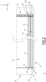
- FIG 1 is a side view of an assembly 10 in an assembled configuration.
- the assembly 10 is intended for the formation of an electrical member 12, of module or battery type, visible in top view on the figure 2 .
- the assembly 10 comprises a support 14 and at least one first electrochemical cell 16.
- the assembly 10 further comprises a second electrochemical cell 116, visible on the figure 2 .
- the assembly 10 comprises a plurality of electrochemical cells.
- the assembly 10 further comprises at least one interconnection device 18, visible on the figure 2 .
- the support 14 comprises a bottom 20 and a first 22 and a second 24 fixing devices.
- the bottom 20 is substantially planar and has a first face 26, called the main face, and a second opposite face.
- a first face 26 called the main face
- a second opposite face We consider an orthonormal base (X, Y, Z) associated with the support 14, the direction Z representing the vertical.
- X, Y, Z an orthonormal base associated with the support 14, the direction Z representing the vertical.
- the bottom 20 extends in a plane (X, Y), the main face 26 being oriented upwards.
- the first 22 and second 24 fixing devices are integral with the bottom 20, projecting relative to the main face 26.
- the first 22 and second 24 fixing devices face each other in the direction Y, called the direction of assembly.
- the first fixing device 22 comprises a curved cam surface 30, visible on the Figure 3 .
- the cam surface 30 has the shape of a cylinder portion extending in the direction X.
- the cam surface 30 is a concave surface.
- the first fixing device 22 comprises: a bar 32 extending along X; and a rectilinear groove 34, formed in said bar, facing the second fixing device 24.
- An internal surface of the groove 34 forms the cam surface 30.
- Said groove 34 has for example a U-shaped section, a bottom of said groove having the shape of a portion of a cylinder of revolution.
- the second fixing device 24 comprises at least a first elastically deformable element 40, fixed to the main face 26 of the bottom 20.
- the second fixing device 24 comprises a second element 140 ( figure 2 ) elastically deformable, fixed to the main face 26, the first and second elements 40 and 140 being aligned along X.
- the second fixing device 24 comprises a plurality of elastically deformable elements 40, 140, fixed to the main face 26 and aligned along X. Said elements 40, 140 are identical or similar.
- the number of elastically deformable elements 40, 140 of the second fixing device 24 corresponds in particular to a maximum number of electrochemical cells 16, 116 capable of being assembled to the support 14.
- the second fixing device 24 further comprises an intermediate piece 41.
- Said intermediate piece 41 has the shape of a strip of L-shaped section.
- the intermediate piece 41 is fixed to the main face 26, extending along X, in direct contact with said main face 26.
- the elements 40, 140 are fixed in contact with said intermediate piece 41 and are therefore not in direct contact with the main face 26.
- the second fixing device 24 does not include an intermediate part and the elements 40, 140 are fixed in direct contact with the main face 26.
- the elements 40 and 140 have an identical shape and the same arrangement perpendicular to the direction X. Only the first element 40 will be described below.
- the first elastically deformable element 40 is an elastic blade, preferably metallic.
- Said elastic blade has the shape of a strip extending between a first 42 and a second 44 ends.
- the element 40 comprises a first 46 and a second 48 planar portions, joined by a junction 50.
- first 46 and second 48 planar portions are inclined by an angle a, visible on the figure 4 .
- the angle ⁇ is for example between 45° and 75°.
- the first 46 and second 48 planar portions are preferably inclined by an angle close to, or equal to, the angle a.
- the first flat portion 46 on the side of the first end 42, is arranged substantially horizontally and fixed to the intermediate piece 41.
- the second flat portion 48 is movable elastically relative to the main face 26 of the bottom 20.
- the second flat portion 48 comprises an orifice 52 into which a tool can be introduced to press on said second flat portion 48, as it will be detailed below.
- the junction 50 arranged between the first 46 and second 48 planar portions, is folded or curved in the form of a notch 54 oriented towards the first fixing device 22.
- the notch 54 forms a concave surface, extending along and of substantially U-shaped section. The shape of the notch 54 will be detailed below.
- the first 16 and second 116 electrochemical cells will now be described. More precisely, in the remainder of the description, it is considered that the electrochemical cells of set 10 are identical. Only the first cell 16 will be described below.
- Cell 16 comprises: an external envelope 60; and at least one electrical terminal 62, 64, arranged on said external envelope. More precisely, the cell preferably comprises a positive terminal 62 and a negative terminal 64.
- the outer envelope 60 extends in a longitudinal direction, between a first 66 and a second 68 end. In the assembled configuration of the figure 1 , the longitudinal direction is parallel to Y.
- the outer envelope 60 has a generally parallelepiped shape. More precisely, each of the first 66 and second 68 ends respectively comprises a first 70 and a second 72 end faces. Said end faces are substantially planar and parallel to each other. In the assembled configuration of the figure 1 , the first 70 and second 72 end faces are arranged in planes (X, Z).
- each side face 74 is arranged in a plane (Y, Z).
- the outer envelope 60 comprises an upper face 76 and a lower face 78, arranged in planes (X, Y) in the assembled configuration of the figure 1 .
- the outer envelope 60 also comprises a first 80 and a second 82 removable assembly members, respectively with the first 22 and with the second 24 fixing device.
- the external envelope 60 comprises a first 80 and a second 82 lugs, projecting relative, respectively, to the first 70 and to the second 72 faces end.
- Each of the first 80 and second 82 lugs is arranged close to the lower face 78.
- the first 80 and second 82 lugs are identical and will be described simultaneously below. More precisely, in the embodiment shown, the external envelope 60 of the first electrochemical cell 16 is of substantially symmetrical shape along a plane perpendicular to the longitudinal direction.
- the lug 80, 82 extends over a part, and preferably over the entirety, of a width of the first 70 or second 72 end face, between the lateral faces 74.
- the lug 80, 82 forms a cylindrical surface extending perpendicular to the longitudinal direction of the cell 16. More precisely, said cylindrical surface comprises a flat part 84 and a curved part 86.
- planar 84 and curved 86 parts are adjacent to the end face 70, 72 carrying the lug 80, 82.
- the planar 84 and curved 86 parts meet at a projecting edge 88, perpendicular to the longitudinal direction of cell 16.
- the flat part 84 is substantially oriented towards the upper face 76 of the envelope 60.
- the curved part 86 forms a counter-cam surface, capable of cooperating with the cam surface 30 of the first fixing device 22, as will be described below. More precisely, the curved part 86 has a shape substantially complementary to the cam surface 30.
- the concave surface of the notch 54 of the elastically deformable element 40, 140 of the second fixing device 24 is substantially complementary to the projecting edge 88 and a portion of each of the flat 84 and curved 86 parts, adjacent to said edge.
- first and a second removable assembly members carried by the external envelope of the electrochemical cell 16, 116 comprise concave surfaces; and the first 22 and second 24 fixing devices comprise complementary convex surfaces.
- each of the electrical terminals 62, 64 of the electrochemical cell 16 is arranged on one of the first 70 and second 72 end faces, so that the positive terminals 62 and negative 64 are at the opposite of each other.
- the positive terminal 62 of the first cell 16 is carried by the first end face 70 and the negative terminal 64 is carried by the second end face 72.
- the electrical terminals are arranged on the same end face, or even on the upper face 76 of the external envelope.
- the support 14 and the first electrochemical cell 16 are dissociated from each other.
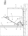
- the first cell 16 is arranged above the support 14 and inclined relative to the main face 26 of the bottom 20, the first end face 70 thus being lower than the second end face 72. More precisely, the first cell 16 is arranged so that the side walls 74 are located in planes (Y, Z) and the lower face 78 forms an angle ⁇ with the horizontal, as visible on the Figure 5 .
- the angle ⁇ is between 5° and 75°, preferably between 10° and 60°, more preferably between 20° and 45°.
- the first lug 80 is inserted into the groove 34 of the first fixing device 22, the curved part 86 of said first lug thus being in contact with the cam surface 30 formed by said groove 34.
- the part curve 86 then substantially matches the cam surface 30.
- the first plane of rotation 90 is a median plane of the first element 40, elastically deformable, of the second fixing device 24.
- the first cell 16 is then in a position called the first initial position, visible on the figure 5 .
- a rotational movement is then applied to the first cell in the first plane of rotation 90, so as to bring the second end face 72 closer to the support 14.
- the curved part 86 of the first lug 80 slides against the cam surface 30 of the groove 34.
- the movement of the first cell 16 relative to the support 14 is essentially a rotational movement around an axis parallel to and the counter-surface 86 of the cam.
- the rotational movement presents the second lug 82 facing the notch 54 of the first element 40.
- the first element 40 is then elastically deformed by bringing the first 46 and second 48 flat portions closer to each other. This deformation makes it possible to rule out the lips of the notch 54 and to elastically fit said notch onto the second lug 82.
- the second lug 82 during the rotation of the first cell 16, which presses on the first element 40 and allows the notch 54 to be clipped onto said second lug.
- the notch 54 of the first element 40 being fitted onto the second lug 82, the first cell is in a position called the first final position, corresponding to the assembled configuration of the figure 1 .
- an assembly method further comprises the following steps: first of all, the second electrochemical cell 116 is brought closer to the support 14. More precisely, a median plane (Y, Z) of the second cell 116 is arranged in a plane (Y, Z) called second plane of rotation 190, visible on the figure 2 .
- the second plane of rotation 190 is a median plane of the second element 140, of the second fixing device 24, adjacent to the first element 40.
- the first lug 80 of the second cell 116 is inserted into the groove 34 to place the second cell in a second initial position, similar to the first initial position previously described for the first cell 16.
- the face chosen as the first end face 70 for the second cell 116 depends on the polarity of the terminal 62, 64 carried by said face.
- the first end face of the first cell 16 carries a positive terminal 62 and the first end face of the second cell 116 carries a negative terminal 64.
- the second cell 116 is assembled fixed in translation along Y and Z relative to the support 14.
- the configuration of the support 14 and the cells 16, 116 facilitates the assembly process, thus increasing the speed of assembly of a module or pack.
- There manufacturing the external envelope of the cells is also simplified by the identical shape of the lugs 80 and 82.
- several cells are prepositioned at one end of the first device 22, by inserting the first lug 80 into the groove 34; then the assembly method described above is successively applied to each cell starting with the movement according to
- the upper faces 76 of the first 16 and second 116 cells are then substantially coplanar and their side faces 74 are parallel.
- the positive terminal 62 of one of the first and second cells is located close to the negative terminal 64 of the other of the first and second cells.
- the first 16 and second 116 cells are then electrically connected by the interconnection device 18.
- the positive terminal 62 of the first cell 16 is connected to the negative terminal 64 of the second cell 116.
- the first and second cells are thus connected in series.
- the second fixing device 24 comprises a plurality of elastically deformable elements, similar to the first 40 and the second 140 elements; and the assembly of the assembly 10 or the production of the electrical member 12 then comprises the assembly of a plurality of electrochemical cells, similar to the first and second cells, to the support 14. Each electrochemical cell is in particular assembled at the one of the elastically deformable elements of the second fixing device 24.
- the cells are then electrically connected two by two by interconnection devices, similar to the interconnection device 18.
- the embodiment shown illustrates the case of cells 16, 116 connected in series.
- the support 14 also allows assembly with electrochemical cells 16, 116 for electrical assembly in parallel.
- the assembly 10 and the electrical member 12 described above allow individual dismantling of one of the electrochemical cells, for example for maintenance or replacement.
- a dismantling method is described below, for which we consider the case of a cell 16 whose location is arbitrary along X in the support 14.
- the interconnection device(s) 18, possibly connected to the cell 16 concerned, are dissociated from said cell.
- a point-type tool is introduced into the orifice 52 of the element 40 of the second fixing device 24, assembled to said cell. Support is exerted on the tool to bring the first 46 and second 48 flat portions together and separate the lips of the notch 54 of the element 40.
- the second end face 72 is moved upwards, which makes it possible to release the second lug 82 from the notch 54 and to pivot the first lug 80 in the groove 34 of the first fixing device.
- the first lug 80 is extracted from the groove 34. The cell 16 is thus separated from the support 14.
- the support for spreading the lips of the notch 54 is made by hand by the operator, on the second end 44 of the element 40.
- the point type tool is therefore not essential for dismantling cells.
- This disassembly process makes it possible to individually replace cells 16, 116 in the electrical member 12 made from the assembly 10, which facilitates the maintenance of said electrical member.
Landscapes
- Chemical & Material Sciences (AREA)
- Chemical Kinetics & Catalysis (AREA)
- Electrochemistry (AREA)
- General Chemical & Material Sciences (AREA)
- Battery Mounting, Suspending (AREA)
- Connection Of Batteries Or Terminals (AREA)
- Electric Double-Layer Capacitors Or The Like (AREA)
Priority Applications (2)
| Application Number | Priority Date | Filing Date | Title |
|---|---|---|---|
| EP22305672.2A EP4274009A1 (de) | 2022-05-05 | 2022-05-05 | Anordnung zur bildung eines elektrischen organs mit elektrochemischen zellen und entsprechendes montageverfahren |
| PCT/EP2023/061627 WO2023213855A2 (fr) | 2022-05-05 | 2023-05-03 | Ensemble pour la formation d'un organe électrique comprenant des cellules électrochimiques et procédé de montage associé |
Applications Claiming Priority (1)
| Application Number | Priority Date | Filing Date | Title |
|---|---|---|---|
| EP22305672.2A EP4274009A1 (de) | 2022-05-05 | 2022-05-05 | Anordnung zur bildung eines elektrischen organs mit elektrochemischen zellen und entsprechendes montageverfahren |
Publications (1)
| Publication Number | Publication Date |
|---|---|
| EP4274009A1 true EP4274009A1 (de) | 2023-11-08 |
Family
ID=82270611
Family Applications (1)
| Application Number | Title | Priority Date | Filing Date |
|---|---|---|---|
| EP22305672.2A Pending EP4274009A1 (de) | 2022-05-05 | 2022-05-05 | Anordnung zur bildung eines elektrischen organs mit elektrochemischen zellen und entsprechendes montageverfahren |
Country Status (2)
| Country | Link |
|---|---|
| EP (1) | EP4274009A1 (de) |
| WO (1) | WO2023213855A2 (de) |
Citations (2)
| Publication number | Priority date | Publication date | Assignee | Title |
|---|---|---|---|---|
| EP2840627A1 (de) * | 2012-05-21 | 2015-02-25 | LG Chem, Ltd. | Anordnung zur befestigung eines batteriemoduls und verfahren zur montage des batteriemoduls auf einer grundplatte |
| EP2293362B1 (de) * | 2008-06-30 | 2018-01-17 | LG Chem, Ltd. | Batteriemontagesystem |
Family Cites Families (1)
| Publication number | Priority date | Publication date | Assignee | Title |
|---|---|---|---|---|
| DE102011077330A1 (de) * | 2011-06-10 | 2012-12-13 | Sb Limotive Company Ltd. | Batterie, Kraftfahrzeug mit dieser Batterie und Verfahren zur Montage dieser Batterie |
-
2022
- 2022-05-05 EP EP22305672.2A patent/EP4274009A1/de active Pending
-
2023
- 2023-05-03 WO PCT/EP2023/061627 patent/WO2023213855A2/fr unknown
Patent Citations (2)
| Publication number | Priority date | Publication date | Assignee | Title |
|---|---|---|---|---|
| EP2293362B1 (de) * | 2008-06-30 | 2018-01-17 | LG Chem, Ltd. | Batteriemontagesystem |
| EP2840627A1 (de) * | 2012-05-21 | 2015-02-25 | LG Chem, Ltd. | Anordnung zur befestigung eines batteriemoduls und verfahren zur montage des batteriemoduls auf einer grundplatte |
Also Published As
| Publication number | Publication date |
|---|---|
| WO2023213855A3 (fr) | 2024-02-22 |
| WO2023213855A2 (fr) | 2023-11-09 |
Similar Documents
| Publication | Publication Date | Title |
|---|---|---|
| EP2809537B1 (de) | Gehäuse für ein elektrisches modul eines batteriepacks für ein kraftfahrzeug und zugehöriges batteriepack | |
| CA2697231C (fr) | Batterie constituee d'une pluralite de cellules positionnees et reliees entre elles, sans soudure | |
| EP2875547B1 (de) | Batteriemodul mit komprimierten zellen | |
| EP2845243B1 (de) | Energiespeichermodul mit mehreren energiespeicherelementen und verbesserten mitteln zur wärmeableitung sowie verfahren zur anordnung | |
| EP2286492B1 (de) | Bürstenhaltereinrichtung und verwendung dafür zur herstellung eines kraftfahrzeuganlassers | |
| WO2018211204A1 (fr) | Dispositif de refroidissement pour une batterie de vehicule automobile | |
| EP1520322A1 (de) | Verbindungseinrichtung für flexible schaltung | |
| EP0209717B1 (de) | Batteriekammer für elektronische Uhr | |
| FR2988915A3 (fr) | Structure de module de batterie pour cellules li-ion a enveloppe souple et module de batterie correspondant | |
| EP4274009A1 (de) | Anordnung zur bildung eines elektrischen organs mit elektrochemischen zellen und entsprechendes montageverfahren | |
| FR2988914A3 (fr) | Structure de module de batterie a assemblage simplifie pour cellules li-ion a enveloppe souple et un module correspondant | |
| WO2023213860A2 (fr) | Ensemble pour la formation d'un organe électrique comprenant des cellules électrochimiques et procédés de montage et de démontage associés | |
| EP4391129A1 (de) | Batterieanordnung mit einer oder mehreren elektrochemischen zellen und verfahren zur montage einer solchen anordnung | |
| EP4207474A1 (de) | Einheit zur elastischen verbindung von elektrochemischen zellen und entsprechendes installationsverfahren | |
| EP0969533A1 (de) | Spannvorrichtung für Monoblock-Batterie | |
| EP4207439A1 (de) | Verbindungsvorrichtung, entsprechende anordnung und entsprechendes verbindungsverfahren | |
| WO2023126398A1 (fr) | Ensemble d'interconnexion de cellules électrochimiques et procédé d'installation associé | |
| WO2023152152A1 (fr) | Ensemble d'interconnexion élastique de cellules électrochimiques et procédé d'installation associé | |
| WO2023126433A1 (fr) | Ensemble et procédé d'interconnexion électrique | |
| FR3091959A1 (fr) | Procédé de montage d’un connecteur femelle de puissance à lame de contact précontrainte | |
| EP4383411A1 (de) | Elektrochemische zelle für eine batterie mit einem kontaktelement zum einklemmen einer vielzahl von elektroden eines stapels und zum verbinden mit einer klemme | |
| WO2024028033A1 (fr) | Dispositif pour le maintien d'un élément de stockage d'énergie sur un socle d'un système de stockage d'énergie | |
| WO2021245259A1 (fr) | Organe de connexion pour relier deux accumulateurs | |
| FR3102891A1 (fr) | Batterie de stockage d’électricité, notamment pour un véhicule automobile | |
| FR3144893A1 (fr) | Dispositif de batterie, notamment pour véhicule |
Legal Events
| Date | Code | Title | Description |
|---|---|---|---|
| PUAI | Public reference made under article 153(3) epc to a published international application that has entered the european phase |
Free format text: ORIGINAL CODE: 0009012 |
|
| STAA | Information on the status of an ep patent application or granted ep patent |
Free format text: STATUS: THE APPLICATION HAS BEEN PUBLISHED |
|
| AK | Designated contracting states |
Kind code of ref document: A1 Designated state(s): AL AT BE BG CH CY CZ DE DK EE ES FI FR GB GR HR HU IE IS IT LI LT LU LV MC MK MT NL NO PL PT RO RS SE SI SK SM TR |
|
| P01 | Opt-out of the competence of the unified patent court (upc) registered |
Effective date: 20231116 |
|
| STAA | Information on the status of an ep patent application or granted ep patent |
Free format text: STATUS: REQUEST FOR EXAMINATION WAS MADE |
|
| 17P | Request for examination filed |
Effective date: 20240409 |
|
| RBV | Designated contracting states (corrected) |
Designated state(s): AL AT BE BG CH CY CZ DE DK EE ES FI FR GB GR HR HU IE IS IT LI LT LU LV MC MK MT NL NO PL PT RO RS SE SI SK SM TR |