EP4273953A1 - Electrode plate, and secondary battery comprising same - Google Patents
Electrode plate, and secondary battery comprising same Download PDFInfo
- Publication number
- EP4273953A1 EP4273953A1 EP22908815.8A EP22908815A EP4273953A1 EP 4273953 A1 EP4273953 A1 EP 4273953A1 EP 22908815 A EP22908815 A EP 22908815A EP 4273953 A1 EP4273953 A1 EP 4273953A1
- Authority
- EP
- European Patent Office
- Prior art keywords
- insulating portion
- electrode plate
- tabs
- main body
- present application
- Prior art date
- Legal status (The legal status is an assumption and is not a legal conclusion. Google has not performed a legal analysis and makes no representation as to the accuracy of the status listed.)
- Pending
Links
- 239000011149 active material Substances 0.000 claims abstract description 10
- 229920000642 polymer Polymers 0.000 claims description 30
- 239000010410 layer Substances 0.000 claims description 27
- 238000012545 processing Methods 0.000 claims description 17
- 239000000463 material Substances 0.000 claims description 14
- 239000000919 ceramic Substances 0.000 claims description 10
- 229920000098 polyolefin Polymers 0.000 claims description 6
- 230000008018 melting Effects 0.000 claims description 5
- 238000002844 melting Methods 0.000 claims description 5
- 239000011247 coating layer Substances 0.000 claims description 4
- 238000009413 insulation Methods 0.000 abstract description 3
- -1 polypropylene Polymers 0.000 description 23
- 239000002033 PVDF binder Substances 0.000 description 16
- 239000004698 Polyethylene Substances 0.000 description 16
- 238000000034 method Methods 0.000 description 16
- 229920000573 polyethylene Polymers 0.000 description 16
- 229920002981 polyvinylidene fluoride Polymers 0.000 description 16
- SECXISVLQFMRJM-UHFFFAOYSA-N N-Methylpyrrolidone Chemical compound CN1CCCC1=O SECXISVLQFMRJM-UHFFFAOYSA-N 0.000 description 13
- 238000005520 cutting process Methods 0.000 description 12
- 239000002245 particle Substances 0.000 description 12
- 239000003792 electrolyte Substances 0.000 description 10
- OKTJSMMVPCPJKN-UHFFFAOYSA-N Carbon Chemical compound [C] OKTJSMMVPCPJKN-UHFFFAOYSA-N 0.000 description 9
- 239000007774 positive electrode material Substances 0.000 description 9
- 239000011230 binding agent Substances 0.000 description 8
- 239000011248 coating agent Substances 0.000 description 8
- 238000000576 coating method Methods 0.000 description 8
- 239000002131 composite material Substances 0.000 description 8
- 239000011888 foil Substances 0.000 description 8
- 239000004743 Polypropylene Substances 0.000 description 7
- 239000000654 additive Substances 0.000 description 7
- 230000000996 additive effect Effects 0.000 description 7
- 229910001593 boehmite Inorganic materials 0.000 description 7
- 239000006258 conductive agent Substances 0.000 description 7
- 239000011267 electrode slurry Substances 0.000 description 7
- FAHBNUUHRFUEAI-UHFFFAOYSA-M hydroxidooxidoaluminium Chemical compound O[Al]=O FAHBNUUHRFUEAI-UHFFFAOYSA-M 0.000 description 7
- 229910001416 lithium ion Inorganic materials 0.000 description 7
- 239000007773 negative electrode material Substances 0.000 description 7
- 229920001155 polypropylene Polymers 0.000 description 7
- HBBGRARXTFLTSG-UHFFFAOYSA-N Lithium ion Chemical compound [Li+] HBBGRARXTFLTSG-UHFFFAOYSA-N 0.000 description 6
- 229910052782 aluminium Inorganic materials 0.000 description 6
- XAGFODPZIPBFFR-UHFFFAOYSA-N aluminium Chemical compound [Al] XAGFODPZIPBFFR-UHFFFAOYSA-N 0.000 description 6
- 239000008151 electrolyte solution Substances 0.000 description 6
- 229910052751 metal Inorganic materials 0.000 description 6
- 239000002184 metal Substances 0.000 description 6
- 239000002861 polymer material Substances 0.000 description 6
- 238000002360 preparation method Methods 0.000 description 6
- 239000002002 slurry Substances 0.000 description 6
- WHXSMMKQMYFTQS-UHFFFAOYSA-N Lithium Chemical compound [Li] WHXSMMKQMYFTQS-UHFFFAOYSA-N 0.000 description 5
- 230000000052 comparative effect Effects 0.000 description 5
- 230000000694 effects Effects 0.000 description 5
- 229910052744 lithium Inorganic materials 0.000 description 5
- 229920001707 polybutylene terephthalate Polymers 0.000 description 5
- 239000000243 solution Substances 0.000 description 5
- 239000002904 solvent Substances 0.000 description 5
- PXHVJJICTQNCMI-UHFFFAOYSA-N Nickel Chemical compound [Ni] PXHVJJICTQNCMI-UHFFFAOYSA-N 0.000 description 4
- 238000010586 diagram Methods 0.000 description 4
- 238000001035 drying Methods 0.000 description 4
- VNWKTOKETHGBQD-UHFFFAOYSA-N methane Chemical compound C VNWKTOKETHGBQD-UHFFFAOYSA-N 0.000 description 4
- 229920000139 polyethylene terephthalate Polymers 0.000 description 4
- 239000005020 polyethylene terephthalate Substances 0.000 description 4
- XEKOWRVHYACXOJ-UHFFFAOYSA-N Ethyl acetate Chemical compound CCOC(C)=O XEKOWRVHYACXOJ-UHFFFAOYSA-N 0.000 description 3
- ZMXDDKWLCZADIW-UHFFFAOYSA-N N,N-Dimethylformamide Chemical compound CN(C)C=O ZMXDDKWLCZADIW-UHFFFAOYSA-N 0.000 description 3
- 229910019142 PO4 Inorganic materials 0.000 description 3
- RTAQQCXQSZGOHL-UHFFFAOYSA-N Titanium Chemical compound [Ti] RTAQQCXQSZGOHL-UHFFFAOYSA-N 0.000 description 3
- 150000001721 carbon Chemical class 0.000 description 3
- 239000006229 carbon black Substances 0.000 description 3
- 238000004146 energy storage Methods 0.000 description 3
- 235000021317 phosphate Nutrition 0.000 description 3
- 229920003023 plastic Polymers 0.000 description 3
- 239000004033 plastic Substances 0.000 description 3
- 238000003825 pressing Methods 0.000 description 3
- 239000000758 substrate Substances 0.000 description 3
- 238000012360 testing method Methods 0.000 description 3
- IXPNQXFRVYWDDI-UHFFFAOYSA-N 1-methyl-2,4-dioxo-1,3-diazinane-5-carboximidamide Chemical compound CN1CC(C(N)=N)C(=O)NC1=O IXPNQXFRVYWDDI-UHFFFAOYSA-N 0.000 description 2
- 229910001316 Ag alloy Inorganic materials 0.000 description 2
- RYGMFSIKBFXOCR-UHFFFAOYSA-N Copper Chemical compound [Cu] RYGMFSIKBFXOCR-UHFFFAOYSA-N 0.000 description 2
- 229910000990 Ni alloy Inorganic materials 0.000 description 2
- 229920002845 Poly(methacrylic acid) Polymers 0.000 description 2
- 239000004793 Polystyrene Substances 0.000 description 2
- 239000004372 Polyvinyl alcohol Substances 0.000 description 2
- BQCADISMDOOEFD-UHFFFAOYSA-N Silver Chemical compound [Ag] BQCADISMDOOEFD-UHFFFAOYSA-N 0.000 description 2
- 229910001069 Ti alloy Inorganic materials 0.000 description 2
- 239000006230 acetylene black Substances 0.000 description 2
- PNEYBMLMFCGWSK-UHFFFAOYSA-N aluminium oxide Inorganic materials [O-2].[O-2].[O-2].[Al+3].[Al+3] PNEYBMLMFCGWSK-UHFFFAOYSA-N 0.000 description 2
- 229910052799 carbon Inorganic materials 0.000 description 2
- 239000002134 carbon nanofiber Substances 0.000 description 2
- 229910021393 carbon nanotube Inorganic materials 0.000 description 2
- 239000002041 carbon nanotube Substances 0.000 description 2
- 150000001875 compounds Chemical class 0.000 description 2
- 125000002573 ethenylidene group Chemical group [*]=C=C([H])[H] 0.000 description 2
- FKRCODPIKNYEAC-UHFFFAOYSA-N ethyl propionate Chemical compound CCOC(=O)CC FKRCODPIKNYEAC-UHFFFAOYSA-N 0.000 description 2
- 229910021389 graphene Inorganic materials 0.000 description 2
- 239000003273 ketjen black Substances 0.000 description 2
- GELKBWJHTRAYNV-UHFFFAOYSA-K lithium iron phosphate Chemical compound [Li+].[Fe+2].[O-]P([O-])([O-])=O GELKBWJHTRAYNV-UHFFFAOYSA-K 0.000 description 2
- 229910021437 lithium-transition metal oxide Inorganic materials 0.000 description 2
- DVATZODUVBMYHN-UHFFFAOYSA-K lithium;iron(2+);manganese(2+);phosphate Chemical compound [Li+].[Mn+2].[Fe+2].[O-]P([O-])([O-])=O DVATZODUVBMYHN-UHFFFAOYSA-K 0.000 description 2
- ILXAVRFGLBYNEJ-UHFFFAOYSA-K lithium;manganese(2+);phosphate Chemical compound [Li+].[Mn+2].[O-]P([O-])([O-])=O ILXAVRFGLBYNEJ-UHFFFAOYSA-K 0.000 description 2
- 239000007769 metal material Substances 0.000 description 2
- TZIHFWKZFHZASV-UHFFFAOYSA-N methyl formate Chemical compound COC=O TZIHFWKZFHZASV-UHFFFAOYSA-N 0.000 description 2
- 229910052759 nickel Inorganic materials 0.000 description 2
- 239000010450 olivine Substances 0.000 description 2
- 229910052609 olivine Inorganic materials 0.000 description 2
- 150000003013 phosphoric acid derivatives Chemical class 0.000 description 2
- 229920002401 polyacrylamide Polymers 0.000 description 2
- 229920001343 polytetrafluoroethylene Polymers 0.000 description 2
- 239000004810 polytetrafluoroethylene Substances 0.000 description 2
- 229920002451 polyvinyl alcohol Polymers 0.000 description 2
- 150000003839 salts Chemical class 0.000 description 2
- 239000002210 silicon-based material Substances 0.000 description 2
- 229910052709 silver Inorganic materials 0.000 description 2
- 239000004332 silver Substances 0.000 description 2
- 239000000661 sodium alginate Substances 0.000 description 2
- 235000010413 sodium alginate Nutrition 0.000 description 2
- 229940005550 sodium alginate Drugs 0.000 description 2
- HHVIBTZHLRERCL-UHFFFAOYSA-N sulfonyldimethane Chemical compound CS(C)(=O)=O HHVIBTZHLRERCL-UHFFFAOYSA-N 0.000 description 2
- 229920001897 terpolymer Polymers 0.000 description 2
- 239000011366 tin-based material Substances 0.000 description 2
- 239000010936 titanium Substances 0.000 description 2
- 229910052719 titanium Inorganic materials 0.000 description 2
- 238000004804 winding Methods 0.000 description 2
- ZZXUZKXVROWEIF-UHFFFAOYSA-N 1,2-butylene carbonate Chemical compound CCC1COC(=O)O1 ZZXUZKXVROWEIF-UHFFFAOYSA-N 0.000 description 1
- HNAGHMKIPMKKBB-UHFFFAOYSA-N 1-benzylpyrrolidine-3-carboxamide Chemical compound C1C(C(=O)N)CCN1CC1=CC=CC=C1 HNAGHMKIPMKKBB-UHFFFAOYSA-N 0.000 description 1
- MBDUIEKYVPVZJH-UHFFFAOYSA-N 1-ethylsulfonylethane Chemical compound CCS(=O)(=O)CC MBDUIEKYVPVZJH-UHFFFAOYSA-N 0.000 description 1
- YBJCDTIWNDBNTM-UHFFFAOYSA-N 1-methylsulfonylethane Chemical compound CCS(C)(=O)=O YBJCDTIWNDBNTM-UHFFFAOYSA-N 0.000 description 1
- UHOPWFKONJYLCF-UHFFFAOYSA-N 2-(2-sulfanylethyl)isoindole-1,3-dione Chemical compound C1=CC=C2C(=O)N(CCS)C(=O)C2=C1 UHOPWFKONJYLCF-UHFFFAOYSA-N 0.000 description 1
- YEJRWHAVMIAJKC-UHFFFAOYSA-N 4-Butyrolactone Chemical compound O=C1CCCO1 YEJRWHAVMIAJKC-UHFFFAOYSA-N 0.000 description 1
- SBLRHMKNNHXPHG-UHFFFAOYSA-N 4-fluoro-1,3-dioxolan-2-one Chemical compound FC1COC(=O)O1 SBLRHMKNNHXPHG-UHFFFAOYSA-N 0.000 description 1
- 239000004925 Acrylic resin Substances 0.000 description 1
- 229910000838 Al alloy Inorganic materials 0.000 description 1
- 229920001661 Chitosan Polymers 0.000 description 1
- 229910000881 Cu alloy Inorganic materials 0.000 description 1
- OIFBSDVPJOWBCH-UHFFFAOYSA-N Diethyl carbonate Chemical compound CCOC(=O)OCC OIFBSDVPJOWBCH-UHFFFAOYSA-N 0.000 description 1
- KMTRUDSVKNLOMY-UHFFFAOYSA-N Ethylene carbonate Chemical compound O=C1OCCO1 KMTRUDSVKNLOMY-UHFFFAOYSA-N 0.000 description 1
- YCKRFDGAMUMZLT-UHFFFAOYSA-N Fluorine atom Chemical compound [F] YCKRFDGAMUMZLT-UHFFFAOYSA-N 0.000 description 1
- JGFBQFKZKSSODQ-UHFFFAOYSA-N Isothiocyanatocyclopropane Chemical compound S=C=NC1CC1 JGFBQFKZKSSODQ-UHFFFAOYSA-N 0.000 description 1
- 229910032387 LiCoO2 Inorganic materials 0.000 description 1
- 229910052493 LiFePO4 Inorganic materials 0.000 description 1
- 229910002993 LiMnO2 Inorganic materials 0.000 description 1
- 229910000668 LiMnPO4 Inorganic materials 0.000 description 1
- 229910012619 LiNi0.5Co0.25Mn0.25O2 Inorganic materials 0.000 description 1
- 229910002991 LiNi0.5Co0.2Mn0.3O2 Inorganic materials 0.000 description 1
- 229910011328 LiNi0.6Co0.2Mn0.2O2 Inorganic materials 0.000 description 1
- 229910015872 LiNi0.8Co0.1Mn0.1O2 Inorganic materials 0.000 description 1
- 229910003005 LiNiO2 Inorganic materials 0.000 description 1
- 229910001228 Li[Ni1/3Co1/3Mn1/3]O2 (NCM 111) Inorganic materials 0.000 description 1
- 229910000572 Lithium Nickel Cobalt Manganese Oxide (NCM) Inorganic materials 0.000 description 1
- 229910002097 Lithium manganese(III,IV) oxide Inorganic materials 0.000 description 1
- JLVVSXFLKOJNIY-UHFFFAOYSA-N Magnesium ion Chemical compound [Mg+2] JLVVSXFLKOJNIY-UHFFFAOYSA-N 0.000 description 1
- RJUFJBKOKNCXHH-UHFFFAOYSA-N Methyl propionate Chemical compound CCC(=O)OC RJUFJBKOKNCXHH-UHFFFAOYSA-N 0.000 description 1
- AUBNQVSSTJZVMY-UHFFFAOYSA-M P(=O)([O-])(O)O.C(C(=O)O)(=O)F.C(C(=O)O)(=O)F.C(C(=O)O)(=O)F.C(C(=O)O)(=O)F.[Li+] Chemical compound P(=O)([O-])(O)O.C(C(=O)O)(=O)F.C(C(=O)O)(=O)F.C(C(=O)O)(=O)F.C(C(=O)O)(=O)F.[Li+] AUBNQVSSTJZVMY-UHFFFAOYSA-M 0.000 description 1
- XBDQKXXYIPTUBI-UHFFFAOYSA-M Propionate Chemical compound CCC([O-])=O XBDQKXXYIPTUBI-UHFFFAOYSA-M 0.000 description 1
- 229910000676 Si alloy Inorganic materials 0.000 description 1
- XUIMIQQOPSSXEZ-UHFFFAOYSA-N Silicon Chemical compound [Si] XUIMIQQOPSSXEZ-UHFFFAOYSA-N 0.000 description 1
- 229910001128 Sn alloy Inorganic materials 0.000 description 1
- FKNQFGJONOIPTF-UHFFFAOYSA-N Sodium cation Chemical compound [Na+] FKNQFGJONOIPTF-UHFFFAOYSA-N 0.000 description 1
- 229920002125 Sokalan® Polymers 0.000 description 1
- 229910000831 Steel Inorganic materials 0.000 description 1
- 229920006172 Tetrafluoroethylene propylene Polymers 0.000 description 1
- ATJFFYVFTNAWJD-UHFFFAOYSA-N Tin Chemical compound [Sn] ATJFFYVFTNAWJD-UHFFFAOYSA-N 0.000 description 1
- HMDDXIMCDZRSNE-UHFFFAOYSA-N [C].[Si] Chemical class [C].[Si] HMDDXIMCDZRSNE-UHFFFAOYSA-N 0.000 description 1
- VIEVWNYBKMKQIH-UHFFFAOYSA-N [Co]=O.[Mn].[Li] Chemical compound [Co]=O.[Mn].[Li] VIEVWNYBKMKQIH-UHFFFAOYSA-N 0.000 description 1
- QTHKJEYUQSLYTH-UHFFFAOYSA-N [Co]=O.[Ni].[Li] Chemical compound [Co]=O.[Ni].[Li] QTHKJEYUQSLYTH-UHFFFAOYSA-N 0.000 description 1
- SYRDSFGUUQPYOB-UHFFFAOYSA-N [Li+].[Li+].[Li+].[O-]B([O-])[O-].FC(=O)C(F)=O Chemical compound [Li+].[Li+].[Li+].[O-]B([O-])[O-].FC(=O)C(F)=O SYRDSFGUUQPYOB-UHFFFAOYSA-N 0.000 description 1
- JDZCKJOXGCMJGS-UHFFFAOYSA-N [Li].[S] Chemical compound [Li].[S] JDZCKJOXGCMJGS-UHFFFAOYSA-N 0.000 description 1
- KFDQGLPGKXUTMZ-UHFFFAOYSA-N [Mn].[Co].[Ni] Chemical compound [Mn].[Co].[Ni] KFDQGLPGKXUTMZ-UHFFFAOYSA-N 0.000 description 1
- UMVBXBACMIOFDO-UHFFFAOYSA-N [N].[Si] Chemical class [N].[Si] UMVBXBACMIOFDO-UHFFFAOYSA-N 0.000 description 1
- FBDMTTNVIIVBKI-UHFFFAOYSA-N [O-2].[Mn+2].[Co+2].[Ni+2].[Li+] Chemical compound [O-2].[Mn+2].[Co+2].[Ni+2].[Li+] FBDMTTNVIIVBKI-UHFFFAOYSA-N 0.000 description 1
- KXKVLQRXCPHEJC-UHFFFAOYSA-N acetic acid trimethyl ester Natural products COC(C)=O KXKVLQRXCPHEJC-UHFFFAOYSA-N 0.000 description 1
- DPXJVFZANSGRMM-UHFFFAOYSA-N acetic acid;2,3,4,5,6-pentahydroxyhexanal;sodium Chemical compound [Na].CC(O)=O.OCC(O)C(O)C(O)C(O)C=O DPXJVFZANSGRMM-UHFFFAOYSA-N 0.000 description 1
- NDPGDHBNXZOBJS-UHFFFAOYSA-N aluminum lithium cobalt(2+) nickel(2+) oxygen(2-) Chemical compound [Li+].[O--].[O--].[O--].[O--].[Al+3].[Co++].[Ni++] NDPGDHBNXZOBJS-UHFFFAOYSA-N 0.000 description 1
- 229910021383 artificial graphite Inorganic materials 0.000 description 1
- 238000000429 assembly Methods 0.000 description 1
- 230000000712 assembly Effects 0.000 description 1
- 238000000231 atomic layer deposition Methods 0.000 description 1
- 239000012752 auxiliary agent Substances 0.000 description 1
- OBNCKNCVKJNDBV-UHFFFAOYSA-N butanoic acid ethyl ester Natural products CCCC(=O)OCC OBNCKNCVKJNDBV-UHFFFAOYSA-N 0.000 description 1
- PWLNAUNEAKQYLH-UHFFFAOYSA-N butyric acid octyl ester Natural products CCCCCCCCOC(=O)CCC PWLNAUNEAKQYLH-UHFFFAOYSA-N 0.000 description 1
- 239000001768 carboxy methyl cellulose Substances 0.000 description 1
- 125000002057 carboxymethyl group Chemical group [H]OC(=O)C([H])([H])[*] 0.000 description 1
- 239000003153 chemical reaction reagent Substances 0.000 description 1
- 238000004891 communication Methods 0.000 description 1
- 239000000470 constituent Substances 0.000 description 1
- 229920001577 copolymer Polymers 0.000 description 1
- 229910052802 copper Inorganic materials 0.000 description 1
- 239000010949 copper Substances 0.000 description 1
- 239000011889 copper foil Substances 0.000 description 1
- 239000008367 deionised water Substances 0.000 description 1
- 229910021641 deionized water Inorganic materials 0.000 description 1
- 238000011161 development Methods 0.000 description 1
- QHGJSLXSVXVKHZ-UHFFFAOYSA-N dilithium;dioxido(dioxo)manganese Chemical compound [Li+].[Li+].[O-][Mn]([O-])(=O)=O QHGJSLXSVXVKHZ-UHFFFAOYSA-N 0.000 description 1
- IEJIGPNLZYLLBP-UHFFFAOYSA-N dimethyl carbonate Chemical compound COC(=O)OC IEJIGPNLZYLLBP-UHFFFAOYSA-N 0.000 description 1
- VUPKGFBOKBGHFZ-UHFFFAOYSA-N dipropyl carbonate Chemical compound CCCOC(=O)OCCC VUPKGFBOKBGHFZ-UHFFFAOYSA-N 0.000 description 1
- 238000007599 discharging Methods 0.000 description 1
- 238000009826 distribution Methods 0.000 description 1
- 229940093499 ethyl acetate Drugs 0.000 description 1
- JBTWLSYIZRCDFO-UHFFFAOYSA-N ethyl methyl carbonate Chemical compound CCOC(=O)OC JBTWLSYIZRCDFO-UHFFFAOYSA-N 0.000 description 1
- CYEDOLFRAIXARV-UHFFFAOYSA-N ethyl propyl carbonate Chemical compound CCCOC(=O)OCC CYEDOLFRAIXARV-UHFFFAOYSA-N 0.000 description 1
- 238000011156 evaluation Methods 0.000 description 1
- 230000008020 evaporation Effects 0.000 description 1
- 238000001704 evaporation Methods 0.000 description 1
- 239000011737 fluorine Substances 0.000 description 1
- 229910052731 fluorine Inorganic materials 0.000 description 1
- 239000003365 glass fiber Substances 0.000 description 1
- 229910021385 hard carbon Inorganic materials 0.000 description 1
- 150000002500 ions Chemical class 0.000 description 1
- 239000007788 liquid Substances 0.000 description 1
- 229910000625 lithium cobalt oxide Inorganic materials 0.000 description 1
- DEUISMFZZMAAOJ-UHFFFAOYSA-N lithium dihydrogen borate oxalic acid Chemical compound B([O-])(O)O.C(C(=O)O)(=O)O.C(C(=O)O)(=O)O.[Li+] DEUISMFZZMAAOJ-UHFFFAOYSA-N 0.000 description 1
- 229910002102 lithium manganese oxide Inorganic materials 0.000 description 1
- FRMOHNDAXZZWQI-UHFFFAOYSA-N lithium manganese(2+) nickel(2+) oxygen(2-) Chemical compound [O-2].[Mn+2].[Ni+2].[Li+] FRMOHNDAXZZWQI-UHFFFAOYSA-N 0.000 description 1
- MHCFAGZWMAWTNR-UHFFFAOYSA-M lithium perchlorate Chemical compound [Li+].[O-]Cl(=O)(=O)=O MHCFAGZWMAWTNR-UHFFFAOYSA-M 0.000 description 1
- 229910001486 lithium perchlorate Inorganic materials 0.000 description 1
- VVNXEADCOVSAER-UHFFFAOYSA-N lithium sodium Chemical compound [Li].[Na] VVNXEADCOVSAER-UHFFFAOYSA-N 0.000 description 1
- 229910001496 lithium tetrafluoroborate Inorganic materials 0.000 description 1
- QSZMZKBZAYQGRS-UHFFFAOYSA-N lithium;bis(trifluoromethylsulfonyl)azanide Chemical compound [Li+].FC(F)(F)S(=O)(=O)[N-]S(=O)(=O)C(F)(F)F QSZMZKBZAYQGRS-UHFFFAOYSA-N 0.000 description 1
- IGILRSKEFZLPKG-UHFFFAOYSA-M lithium;difluorophosphinate Chemical compound [Li+].[O-]P(F)(F)=O IGILRSKEFZLPKG-UHFFFAOYSA-M 0.000 description 1
- BFZPBUKRYWOWDV-UHFFFAOYSA-N lithium;oxido(oxo)cobalt Chemical compound [Li+].[O-][Co]=O BFZPBUKRYWOWDV-UHFFFAOYSA-N 0.000 description 1
- VLXXBCXTUVRROQ-UHFFFAOYSA-N lithium;oxido-oxo-(oxomanganiooxy)manganese Chemical compound [Li+].[O-][Mn](=O)O[Mn]=O VLXXBCXTUVRROQ-UHFFFAOYSA-N 0.000 description 1
- URIIGZKXFBNRAU-UHFFFAOYSA-N lithium;oxonickel Chemical compound [Li].[Ni]=O URIIGZKXFBNRAU-UHFFFAOYSA-N 0.000 description 1
- MCVFFRWZNYZUIJ-UHFFFAOYSA-M lithium;trifluoromethanesulfonate Chemical compound [Li+].[O-]S(=O)(=O)C(F)(F)F MCVFFRWZNYZUIJ-UHFFFAOYSA-M 0.000 description 1
- 229910001425 magnesium ion Inorganic materials 0.000 description 1
- 229940017219 methyl propionate Drugs 0.000 description 1
- KKQAVHGECIBFRQ-UHFFFAOYSA-N methyl propyl carbonate Chemical compound CCCOC(=O)OC KKQAVHGECIBFRQ-UHFFFAOYSA-N 0.000 description 1
- 239000000203 mixture Substances 0.000 description 1
- 238000012986 modification Methods 0.000 description 1
- 230000004048 modification Effects 0.000 description 1
- YKYONYBAUNKHLG-UHFFFAOYSA-N n-Propyl acetate Natural products CCCOC(C)=O YKYONYBAUNKHLG-UHFFFAOYSA-N 0.000 description 1
- UUIQMZJEGPQKFD-UHFFFAOYSA-N n-butyric acid methyl ester Natural products CCCC(=O)OC UUIQMZJEGPQKFD-UHFFFAOYSA-N 0.000 description 1
- 229910021382 natural graphite Inorganic materials 0.000 description 1
- 239000004745 nonwoven fabric Substances 0.000 description 1
- 230000003647 oxidation Effects 0.000 description 1
- 238000007254 oxidation reaction Methods 0.000 description 1
- NBIIXXVUZAFLBC-UHFFFAOYSA-K phosphate Chemical compound [O-]P([O-])([O-])=O NBIIXXVUZAFLBC-UHFFFAOYSA-K 0.000 description 1
- 239000010452 phosphate Substances 0.000 description 1
- 229920001495 poly(sodium acrylate) polymer Polymers 0.000 description 1
- 229920002961 polybutylene succinate Polymers 0.000 description 1
- 239000004631 polybutylene succinate Substances 0.000 description 1
- 238000006116 polymerization reaction Methods 0.000 description 1
- 230000002265 prevention Effects 0.000 description 1
- 229940090181 propyl acetate Drugs 0.000 description 1
- RUOJZAUFBMNUDX-UHFFFAOYSA-N propylene carbonate Chemical compound CC1COC(=O)O1 RUOJZAUFBMNUDX-UHFFFAOYSA-N 0.000 description 1
- 230000001681 protective effect Effects 0.000 description 1
- 239000002994 raw material Substances 0.000 description 1
- 239000010703 silicon Substances 0.000 description 1
- 229910052710 silicon Inorganic materials 0.000 description 1
- LIVNPJMFVYWSIS-UHFFFAOYSA-N silicon monoxide Chemical class [Si-]#[O+] LIVNPJMFVYWSIS-UHFFFAOYSA-N 0.000 description 1
- 229910052814 silicon oxide Inorganic materials 0.000 description 1
- 239000002153 silicon-carbon composite material Substances 0.000 description 1
- 239000002356 single layer Substances 0.000 description 1
- 235000019812 sodium carboxymethyl cellulose Nutrition 0.000 description 1
- 229920001027 sodium carboxymethylcellulose Polymers 0.000 description 1
- 229910001415 sodium ion Inorganic materials 0.000 description 1
- NNMHYFLPFNGQFZ-UHFFFAOYSA-M sodium polyacrylate Chemical compound [Na+].[O-]C(=O)C=C NNMHYFLPFNGQFZ-UHFFFAOYSA-M 0.000 description 1
- 229910021384 soft carbon Inorganic materials 0.000 description 1
- 239000007787 solid Substances 0.000 description 1
- 239000010959 steel Substances 0.000 description 1
- 229920003048 styrene butadiene rubber Polymers 0.000 description 1
- 239000000126 substance Substances 0.000 description 1
- HXJUTPCZVOIRIF-UHFFFAOYSA-N sulfolane Chemical compound O=S1(=O)CCCC1 HXJUTPCZVOIRIF-UHFFFAOYSA-N 0.000 description 1
- 239000002562 thickening agent Substances 0.000 description 1
- 229910052718 tin Inorganic materials 0.000 description 1
- 229910001887 tin oxide Inorganic materials 0.000 description 1
- QHGNHLZPVBIIPX-UHFFFAOYSA-N tin(ii) oxide Chemical class [Sn]=O QHGNHLZPVBIIPX-UHFFFAOYSA-N 0.000 description 1
- NQPDZGIKBAWPEJ-UHFFFAOYSA-N valeric acid Chemical compound CCCCC(O)=O NQPDZGIKBAWPEJ-UHFFFAOYSA-N 0.000 description 1
- XLYOFNOQVPJJNP-UHFFFAOYSA-N water Chemical compound O XLYOFNOQVPJJNP-UHFFFAOYSA-N 0.000 description 1
Images





Classifications
-
- H—ELECTRICITY
- H01—ELECTRIC ELEMENTS
- H01M—PROCESSES OR MEANS, e.g. BATTERIES, FOR THE DIRECT CONVERSION OF CHEMICAL ENERGY INTO ELECTRICAL ENERGY
- H01M4/00—Electrodes
- H01M4/02—Electrodes composed of, or comprising, active material
- H01M4/13—Electrodes for accumulators with non-aqueous electrolyte, e.g. for lithium-accumulators; Processes of manufacture thereof
-
- H—ELECTRICITY
- H01—ELECTRIC ELEMENTS
- H01M—PROCESSES OR MEANS, e.g. BATTERIES, FOR THE DIRECT CONVERSION OF CHEMICAL ENERGY INTO ELECTRICAL ENERGY
- H01M10/00—Secondary cells; Manufacture thereof
- H01M10/05—Accumulators with non-aqueous electrolyte
- H01M10/052—Li-accumulators
-
- H—ELECTRICITY
- H01—ELECTRIC ELEMENTS
- H01M—PROCESSES OR MEANS, e.g. BATTERIES, FOR THE DIRECT CONVERSION OF CHEMICAL ENERGY INTO ELECTRICAL ENERGY
- H01M10/00—Secondary cells; Manufacture thereof
- H01M10/05—Accumulators with non-aqueous electrolyte
- H01M10/054—Accumulators with insertion or intercalation of metals other than lithium, e.g. with magnesium or aluminium
-
- H—ELECTRICITY
- H01—ELECTRIC ELEMENTS
- H01M—PROCESSES OR MEANS, e.g. BATTERIES, FOR THE DIRECT CONVERSION OF CHEMICAL ENERGY INTO ELECTRICAL ENERGY
- H01M4/00—Electrodes
- H01M4/02—Electrodes composed of, or comprising, active material
- H01M4/36—Selection of substances as active materials, active masses, active liquids
- H01M4/362—Composites
- H01M4/366—Composites as layered products
-
- H—ELECTRICITY
- H01—ELECTRIC ELEMENTS
- H01M—PROCESSES OR MEANS, e.g. BATTERIES, FOR THE DIRECT CONVERSION OF CHEMICAL ENERGY INTO ELECTRICAL ENERGY
- H01M4/00—Electrodes
- H01M4/02—Electrodes composed of, or comprising, active material
- H01M4/64—Carriers or collectors
- H01M4/66—Selection of materials
- H01M4/665—Composites
- H01M4/667—Composites in the form of layers, e.g. coatings
-
- H—ELECTRICITY
- H01—ELECTRIC ELEMENTS
- H01M—PROCESSES OR MEANS, e.g. BATTERIES, FOR THE DIRECT CONVERSION OF CHEMICAL ENERGY INTO ELECTRICAL ENERGY
- H01M50/00—Constructional details or processes of manufacture of the non-active parts of electrochemical cells other than fuel cells, e.g. hybrid cells
- H01M50/50—Current conducting connections for cells or batteries
- H01M50/531—Electrode connections inside a battery casing
- H01M50/534—Electrode connections inside a battery casing characterised by the material of the leads or tabs
-
- H—ELECTRICITY
- H01—ELECTRIC ELEMENTS
- H01M—PROCESSES OR MEANS, e.g. BATTERIES, FOR THE DIRECT CONVERSION OF CHEMICAL ENERGY INTO ELECTRICAL ENERGY
- H01M50/00—Constructional details or processes of manufacture of the non-active parts of electrochemical cells other than fuel cells, e.g. hybrid cells
- H01M50/50—Current conducting connections for cells or batteries
- H01M50/572—Means for preventing undesired use or discharge
- H01M50/584—Means for preventing undesired use or discharge for preventing incorrect connections inside or outside the batteries
- H01M50/586—Means for preventing undesired use or discharge for preventing incorrect connections inside or outside the batteries inside the batteries, e.g. incorrect connections of electrodes
-
- H—ELECTRICITY
- H01—ELECTRIC ELEMENTS
- H01M—PROCESSES OR MEANS, e.g. BATTERIES, FOR THE DIRECT CONVERSION OF CHEMICAL ENERGY INTO ELECTRICAL ENERGY
- H01M50/00—Constructional details or processes of manufacture of the non-active parts of electrochemical cells other than fuel cells, e.g. hybrid cells
- H01M50/50—Current conducting connections for cells or batteries
- H01M50/572—Means for preventing undesired use or discharge
- H01M50/584—Means for preventing undesired use or discharge for preventing incorrect connections inside or outside the batteries
- H01M50/59—Means for preventing undesired use or discharge for preventing incorrect connections inside or outside the batteries characterised by the protection means
- H01M50/593—Spacers; Insulating plates
-
- H—ELECTRICITY
- H01—ELECTRIC ELEMENTS
- H01M—PROCESSES OR MEANS, e.g. BATTERIES, FOR THE DIRECT CONVERSION OF CHEMICAL ENERGY INTO ELECTRICAL ENERGY
- H01M10/00—Secondary cells; Manufacture thereof
- H01M10/05—Accumulators with non-aqueous electrolyte
- H01M10/052—Li-accumulators
- H01M10/0525—Rocking-chair batteries, i.e. batteries with lithium insertion or intercalation in both electrodes; Lithium-ion batteries
-
- H—ELECTRICITY
- H01—ELECTRIC ELEMENTS
- H01M—PROCESSES OR MEANS, e.g. BATTERIES, FOR THE DIRECT CONVERSION OF CHEMICAL ENERGY INTO ELECTRICAL ENERGY
- H01M2220/00—Batteries for particular applications
- H01M2220/20—Batteries in motive systems, e.g. vehicle, ship, plane
-
- H—ELECTRICITY
- H01—ELECTRIC ELEMENTS
- H01M—PROCESSES OR MEANS, e.g. BATTERIES, FOR THE DIRECT CONVERSION OF CHEMICAL ENERGY INTO ELECTRICAL ENERGY
- H01M4/00—Electrodes
- H01M4/02—Electrodes composed of, or comprising, active material
- H01M4/13—Electrodes for accumulators with non-aqueous electrolyte, e.g. for lithium-accumulators; Processes of manufacture thereof
- H01M4/139—Processes of manufacture
-
- Y—GENERAL TAGGING OF NEW TECHNOLOGICAL DEVELOPMENTS; GENERAL TAGGING OF CROSS-SECTIONAL TECHNOLOGIES SPANNING OVER SEVERAL SECTIONS OF THE IPC; TECHNICAL SUBJECTS COVERED BY FORMER USPC CROSS-REFERENCE ART COLLECTIONS [XRACs] AND DIGESTS
- Y02—TECHNOLOGIES OR APPLICATIONS FOR MITIGATION OR ADAPTATION AGAINST CLIMATE CHANGE
- Y02E—REDUCTION OF GREENHOUSE GAS [GHG] EMISSIONS, RELATED TO ENERGY GENERATION, TRANSMISSION OR DISTRIBUTION
- Y02E60/00—Enabling technologies; Technologies with a potential or indirect contribution to GHG emissions mitigation
- Y02E60/10—Energy storage using batteries
Definitions
- the present application relates to the field of batteries, and in particular, to an electrode plate and a secondary battery having the same, and a battery module, a battery pack, and a power consuming device.
- the present application has been made in view of the above problems, and an objective of the present application is to provide an electrolyte plate and a secondary battery having the same, and a battery module, a battery pack and a power consuming device.
- the electrode plate has a good end-face insulation protection and can improve the safety performance of the secondary battery.
- a first aspect of the present application provides an electrode plate comprising a current collector and an active material layer, wherein the current collector comprises a main body portion and tabs, the active material layer is coated on the surface of the main body portion, and the tabs extend from one end of the main body portion along the first direction; a first insulating portion is formed on the end face of the main body portion that is provided with the tabs, and a second insulating portion is formed on the end faces of the main body portion that are not provided with the tabs.
- the end face of the current collector Since the end face of the current collector is exposed in the processes of cutting the current collector and processing the tabs, the end face is directly exposed to the electrolyte solution, which increases the probability of internal short circuit caused by the direct contact between the end face and electrodes of opposite polarity.
- the contact between the electrode plates of opposite polarity can be effectively prevented, thus avoiding internal short circuit and increasing the safety performance.
- the surface of the main body portion that is close to the end portion of the tabs is coated with a third insulating portion along the second direction perpendicular to the first direction, and the third insulating portion is connected with the first insulating portion.
- the third insulating portion and the first insulating portion are made of the same material and are integrally formed.
- the first insulating portion can be easily formed.
- the surface of the tabs that is close to the main body portion is coated with a third insulating portion, and the end face of the tabs that is connected with the third insulating portion is provided with a first insulating portion.
- the first insulating portion comprises polymerization
- a polymer has a melting point of 80°C - 300°C.
- the first insulating portion comprises a polymer selected from at least one of polyolefins.
- the end face of the electrode plate can be densely coated, which further increases the safety performance.
- the first insulating portion and the third insulating portion comprise a polymer and ceramic.
- the polymer is selected from at least one of polyolefins, and the mass ratio of the polymer to the ceramic is above 26 : 74. Because the first insulating portion and the third insulating portion comprises the polymer and ceramic, the compactness of the insulating portions can be improved, so that on the one hand, the insulating property of the end face of the electrode plate is ensured, and on the other hand, the damage of the insulating portion is avoided.
- the first insulating portion is formed by laser processing the third insulating portion.
- the insulating portion can be melted by laser processing, and then cured to form a first insulating portion coating the end face, which makes it easy to form the first insulating portion and further increases the safety performance.
- the first insulating portion is an insulating coating layer formed on the end face during the processing of the tabs. Therefore, while the tabs are cut out from the electrode plate coated with the third insulating portion by laser processing, the third insulating portion can be melted and then cured on the end face of the incision to form a first insulating portion coating the end face, which can make it easy to form the first insulating portion and further increase the safety performance.
- a second aspect of the present application provides a secondary battery comprising the electrode plate according to the first aspect of the present application.
- a third aspect of the present application provides a battery module comprising the secondary battery according to the second aspect of the present application.
- a fourth aspect of the present application provides a battery pack comprising the battery module according to the third aspect of the present application.
- a fifth aspect of the present application provides a power consuming device comprising at least one of the secondary battery according to the second aspect of the present application, the battery module according to the third aspect of the present application, and the battery pack according to the forth aspect of the present application.
- the internal short circuit between electrode plates of different polarities can be prevented, thereby improving the safety performance.
- ranges are defined in the form of lower and upper limits.
- a given range is defined by selecting a lower limit and an upper limit, and the selected lower and upper limits defining the boundaries of the particular range. Ranges defined in this manner may be inclusive or exclusive, and may be arbitrarily combined, that is, any lower limit may be combined with any upper limit to form a range. For example, if the ranges of 60-120 and 80-110 are listed for a particular parameter, it should be understood that the ranges of 60-110 and 80-120 are also contemplated. Additionally, if minimum range values 1 and 2 are listed and maximum range values 3, 4, and 5 are listed, the following ranges are all contemplated: 1-3, 1-4, 1-5, 2-3, 2-4 and 2-5.
- the numerical range "a-b” denotes an abbreviated representation of any combination of real numbers between a and b, where both a and b are real numbers.
- the numerical range "0-5" means that all real numbers between "0-5" have been listed in the text, and "0-5" is just an abbreviated representation of combinations of these numerical values.
- a parameter is expressed as an integer ⁇ 2, it is equivalent to disclosing that the parameter is, for example, an integer of 2, 3, 4, 5, 6, 7, 8, 9, 10, 11, 12, etc.
- the term "or” is inclusive unless otherwise specified.
- the phrase “A or B” means “A, B, or both A and B". More specifically, the condition “A or B” is satisfied by any one of the following: A is true (or present) and B is false (or not present); A is false (or not present) and B is true (or present); or both A and B are true (or present).
- FIG. 1 shows a secondary battery 5 with a square structure.
- the secondary battery includes a lithium ion battery, a lithium-sulfur battery, a sodium-lithium ion battery, a sodium ion battery or a magnesium ion battery, etc.
- the concept of the present application will be described below mainly using a lithium ion battery as an example. It should be construed that any other suitable types of rechargeable batteries are all applicable.
- a secondary battery 5 of an example according to the present application comprises a case (comprising a housing 51 and a top cover assembly 53), and an electrode assembly 52.
- the housing 51 may comprise a bottom plate and side plates connected to the bottom plate, and the bottom plate and the side plates enclose to form an accommodating cavity.
- the shape of the housing 51 is not particularly limited in the present application, and may be cylindrical, square or of any other shape.
- the housing 51 has an opening in communication with the accommodating cavity, and the top cover assembly 53 can cover the opening to close the accommodating cavity.
- the electrode assembly 52 is packaged in the accommodating cavity.
- the electrolyte solution infiltrates the electrode assembly 52.
- the number of the electrode assemblies 52 contained in the secondary battery 5 may be one or more, and can be selected by those skilled in the art according to actual requirements.
- the electrode assembly 52 is the core member for a secondary battery to realize the charging and discharging functions.
- the electrode assembly 52 comprises a first electrode plate 6, a second electrode plate 7, and a separator 9, where the separator 9 isolates the first electrode plate 6 and the second electrode plate 7.
- the lithium ion battery operates mainly by relying on the movement of lithium ions between the first electrode plate 6 and the second electrode plate 7 through the separator 9.
- the electrode assembly 52 may be of a winding structure. Specifically, the number of the first electrode plate 6 and the second electrode plate 7 is one, and the first electrode plate 6 and the second electrode plate 7 have a strip-shaped structure. The first electrode plate 6, the separator 9 and the second electrode plate 7 are stacked in sequence and wound for more than two circles to form an electrode assembly 52. The electrode assembly 52 may have a flat shape.
- the electrode assembly 52 may also be of a laminated structure. Specifically, a plurality of first electrode plates 6 and a plurality of second electrode plates 7 are provided, the plurality of first electrode plates 6 and the plurality of second electrode plates 7 are stacked alternately, and a separator 9 is provided to isolate the first electrode plates 6 and the second electrode plates 7.
- Electrodes 55 There are two electrode terminals 55, which are provided on the top cover assembly 53.
- One of the connecting members 54 is used to connect the electrode terminal 55 with the first electrode plate 6 of the electrode assembly 52, and the other connecting member 54 is used to connect the other electrode terminal 55 with the second electrode plate 7 of the electrode assembly 52.
- the present application provides an electrode plate 6 or 7 comprising a current collector 120 and an active material layer 100, wherein the current collector 120 comprises a main body portion 121 and tabs 122, the active material layer 100 is coated on the surface of the main body portion 121, and the tabs 122 extend from one end of the main body portion 121 along the first direction Z; a first insulating portion 200 is formed on the end face of the main body portion 121 that is provided with the tabs 122, while a second insulating portion 210 that is different from the first insulating portion 200 is formed on the end faces of the main body portion 121 that are not provided with the tabs 122.
- the electrode plate is generally sheet-shaped and has a plurality of faces, among which the two faces with the largest area facing each other are called “surfaces”, and the other faces are called “end faces.”
- the end face of the current collector is exposed in the processes of cutting the current collector and processing the tabs, which increases the probability of internal short circuit caused by the direct contact between the end face and the electrodes of opposite polarity.
- a positive electrode current collector the surfaces of an aluminum foil are coated with a positive electrode active material, but the end faces thereof are directly exposed to the electrolyte solution, which increases the probability of short circuits caused by the direct contact between the end face of the aluminum foil and the negative electrode.
- first insulating portion 200 on the end face 121a that is provided with the tabs and forming a second insulating portion 210 on the end faces 121b, 121c, and 121d that are not provided with the tabs, the contact between the electrode plates of opposite polarity can be effectively prevented, thus avoiding internal short circuit and increasing the safety performance.
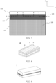
- FIG. 7 shows a schematic cross-sectional view of electrode plates 6 and 7 before processing the tabs.
- the electrode plate 6 or 7 comprises a main body portion 121 and an tab area 123.
- the tab area 123 is provided on one side of the main body portion 121 in the first direction Z.
- the main body portion 121 is coated with an active material layer 100.
- a third insulating portion 110 described later is coated across the main body portion 121 and the tab area 123.
- the tabs 122 are formed by cutting the electrode plates 6 and 7 along the cutting line 124 or by laser processing.
- the first insulating portion 200 is, for example, an insulating coating layer formed on the end face during or after the processing of the tabs 122.
- the second insulating portion 210 is, for example, an insulating coating layer formed on the end face by means of coating etc., after cutting the electrode plate.
- the insulating portion may be prepared by means of polymer coating, oxidation processing, atomic layer deposition, or evaporation, etc.
- the surface of the main body portion 121 that is close to the end portion of the tabs 122 is coated with a third insulating portion 110 in the second direction X perpendicular to the first direction Z, and the third insulating portion 110 is connected with the first insulating portion 200.
- the third insulating portion 110 and the first insulating portion 200 are made of the same material and are integrally formed.
- the first insulating portion 200 can be easily formed, and since the integral structure is relatively dense, the end face of the electrode plate that is exposed in the process of cutting the tabs can be further effectively protected, which further increases the safety performance.
- the surface of the tabs 122 that is close to the main body portion 121 is coated with a third insulating portion 110, and the end face of the tabs 122 that is connected with the third insulating portion 110 is provided with a first insulating portion 200.
- the end face of the electrode plate that is exposed in the process of cutting the tabs can be further effectively protected, which further increases the safety performance.
- the first insulating portion 200 comprises a polymer selected from at least one of polyolefins. With the use of the above polymer to form the first insulating portion 200, the end face of the electrode plate 6 and 7 can be densely coated, which further increases the safety performance.
- the melting point of the above polymer is 80°C - 300°C.
- the first insulating portion 200 and the third insulating portion 110 comprise a polymer and ceramic.
- the polymer is selected from at least one of polyolefins, and the mass ratio of the polymer to the ceramic is above 26 : 74. Because the first insulating portion 200 and the third insulating portion 110 comprises the polymer and ceramic, the compactness of the insulating portions can be improved, so that on the one hand, the insulating property of the end face of the electrode plate is ensured, and on the other hand, the damage of the insulating portion is avoided.
- the first insulating portion 200 is formed by laser processing the third insulating portion 110. Therefore, while the tabs 122 are cut out from the electrode plate coated with the third insulating portion 110 by laser processing, the third insulating portion 110 can be melted and then cured on the end face of the incision to form a first insulating portion 200 coating the end face 121a , which can make it easy to form the first insulating portion and further increase the safety performance.
- the electrode plate shown in FIGS. 4-6 may be used as a positive electrode plate or a negative electrode plate. Since the aluminum foil as a positive electrode current collector is more prone to internal short circuit, the above structure is preferably applied to the positive electrode plate.
- the positive electrode plate comprises a positive electrode current collector and a positive electrode film layer provided on at least one surface of the positive electrode current collector, the positive electrode film layer comprising the positive electrode active material of the first aspect of the present application.
- the positive electrode current collector has two surfaces opposite in its own thickness direction, and the positive electrode film layer is provided on either or both of opposite surfaces of the positive electrode current collector.
- the positive current collector can be a metal foil or a composite current collector.
- a metal foil an aluminum foil can be used.
- the composite current collector may comprise a polymer material base layer and a metal layer formed on at least one surface of the polymer material base layer.
- the composite current collector can be formed by forming a metal material (aluminum, an aluminum alloy, nickel, a nickel alloy, titanium, a titanium alloy, silver and a silver alloy, etc.) on a polymer material substrate (such as polypropylene (PP), polyethylene terephthalate (PET), polybutylene terephthalate (PBT), polystyrene (PS), polyethylene (PE), etc.).
- PP polypropylene
- PET polyethylene terephthalate
- PBT polybutylene terephthalate
- PS polystyrene
- PE polyethylene
- the positive electrode active material can be a positive electrode active material known in the art for batteries.
- the positive electrode active material may comprise at least one of the following materials: lithium-containing phosphates of an olivine structure, lithium transition metal oxides, and their respective modified compounds.
- the present application is not limited to these materials, and other conventional materials that can be used as positive electrode active materials for batteries may also be used.
- These positive electrode active materials may be used alone or in combination of two or more.
- lithium transition metal oxides may include, but are not limited to, at least one of lithium cobalt oxide (e.g. LiCoO2), lithium nickel oxide (e.g. LiNiO2), lithium manganese oxide (e.g.
- LiMnO2, and LiMn2O4 lithium nickel cobalt oxide, lithium manganese cobalt oxide, lithium nickel manganese oxide, lithium nickel cobalt manganese oxide (e.g. LiNi1/3Co1/3Mn1/3O2 (also abbreviated as NCM333), LiNi0.5Co0.2Mn0.3O2 (also abbreviated as NCM523), LiNi0.5Co0.25Mn0.25O2 (also abbreviated as NCM211), LiNi0.6Co0.2Mn0.2O2 (also abbreviated as NCM622), LiNi0.8Co0.1Mn0.1O2 (also abbreviated as NCM811)), lithium nickel cobalt aluminum oxide (e.g. LiNi1/3Co1/3Mn1/3O2 (also abbreviated as NCM333), LiNi0.5Co0.2Mn0.3O2 (also abbreviated as NCM523), LiNi0.5Co0.25Mn0.25O2 (also abbreviated as NCM211), LiNi
- lithium-containing phosphates having olivine structures may include, but are not limited to, at least one of lithium iron phosphate (e.g. LiFePO4 (also referred to as LFP)), lithium iron phosphate and carbon composites, lithium manganese phosphate (e.g. LiMnPO4), lithium manganese phosphate and carbon composites, lithium iron manganese phosphate, and lithium iron manganese phosphate and carbon composites.
- LiFePO4 also referred to as LFP
- LiMnPO4 lithium manganese phosphate and carbon composites
- lithium iron manganese phosphate and carbon composites lithium iron manganese phosphate and carbon composites.
- the positive electrode film layer further comprises a binder.
- the binder may comprise at least one of polyvinylidene fluoride (PVDF), polytetrafluoroethylene (PTFE), vinylidene fluoride-tetrafluoroethylene-propylene terpolymer, vinylidene fluoride-hexafluoropropylene-tetrafluoroethylene terpolymer, tetrafluoroethylene-hexafluoropropylene copolymer, and fluorine-containing acrylate resin.
- PVDF polyvinylidene fluoride
- PTFE polytetrafluoroethylene
- PTFE polytetrafluoroethylene
- vinylidene fluoride-tetrafluoroethylene-propylene terpolymer vinylidene fluoride-hexafluoropropylene-tetrafluoroethylene terpolymer
- the positive electrode film layer further comprises a conductive agent.
- the conductive agent may comprise at least one of superconducting carbon, acetylene black, carbon black, Ketjen black, carbon dots, carbon nanotubes, graphene, and carbon nanofibers.
- the positive electrode plate can be prepared as follows: dispersing the above-mentioned components for preparing the positive electrode plate, such as a positive electrode active material, a conductive agent, a binder and any other components, in a solvent (e.g., N-methyl pyrrolidone) to form a positive electrode slurry; and coating the positive electrode current collector with the positive electrode slurry, followed by the procedures such as drying and cold pressing, so as to obtain the positive electrode plate.
- a solvent e.g., N-methyl pyrrolidone
- the negative electrode plate comprises a negative electrode current collector and a negative electrode film layer provided on at least one surface of the negative electrode current collector, wherein the negative electrode film layer comprises a negative electrode active material.
- the negative electrode current collector has two surfaces opposite in its own thickness direction, and the negative electrode film layer is provided on either or both of the two opposite surfaces of the negative electrode current collector.
- the negative electrode current collector may be a metal foil or a composite current collector.
- a metal foil a copper foil can be used.
- the composite current collector may comprise a polymer material base layer and a metal layer formed on at least one surface of the polymer material substrate.
- the composite current collector can be formed by forming a metal material (copper, a copper alloy, nickel, a nickel alloy, titanium, a titanium alloy, silver and a silver alloy, etc.) on a polymer material substrate (e.g., polypropylene (PP), polyethylene terephthalate (PET), polybutylene terephthalate (PBT), polystyrene (PS), polyethylene (PE), etc.).
- PP polypropylene
- PET polyethylene terephthalate
- PBT polybutylene terephthalate
- PS polystyrene
- PE polyethylene
- the negative electrode active material can be a negative electrode active material known in the art for batteries.
- the negative electrode active material may comprise at least one of the following materials: artificial graphite, natural graphite, soft carbon, hard carbon, a silicon-based material, a tin-based material and lithium titanate, etc.
- the silicon-based material may be selected from at least one of elemental silicon, silicon oxides, silicon carbon composites, silicon nitrogen composites and silicon alloys.
- the tin-based material may be selected from at least one of elemental tin, tin oxides, and tin alloys.
- the present application is not limited to these materials, and other conventional materials that can be used as negative electrode active materials for batteries can also be used. These negative electrode active materials may be used alone or as a combination of two or more.
- the negative electrode film layer further comprises a binder.
- the binder may be selected from at least one of a styrene-butadiene rubber (SBR), polyacrylic acid (PAA), sodium polyacrylate (PAAS), polyacrylamide (PAM), polyvinyl alcohol (PVA), sodium alginate (SA), polymethacrylic acid (PMAA) and carboxymethyl chitosan (CMCS).
- SBR styrene-butadiene rubber
- PAA polyacrylic acid
- PAAS sodium polyacrylate
- PAM polyacrylamide
- PVA polyvinyl alcohol
- SA sodium alginate
- PMAA polymethacrylic acid
- CMCS carboxymethyl chitosan
- the negative electrode film layer further comprises a conductive agent.
- the conductive agent may be selected from at least one of superconductive carbon, acetylene black, carbon black, ketjenblack, carbon dots, carbon nanotubes, graphene, and carbon nanofibers.
- the negative electrode film layer further comprises other auxiliary agents, such as thickener (e.g., sodium carboxymethyl cellulose (CMC-Na)) and the like.
- thickener e.g., sodium carboxymethyl cellulose (CMC-Na)
- CMC-Na sodium carboxymethyl cellulose
- the negative electrode plate can be prepared as follows: dispersing the above-mentioned components for preparing the negative electrode plate, such as negative electrode active material, conductive agent, binder and any other components, in a solvent (e.g. deionized water) to form a negative electrode slurry; and coating a negative electrode current collector with the negative electrode slurry, followed by procedures such as drying and cold pressing, so as to obtain the negative electrode plate.
- a solvent e.g. deionized water
- the electrolyte functions to conduct ions between the positive electrode plate and the negative electrode plate.
- the type of the electrolyte is not specifically limited in the present application, and can be selected according to actual requirements.
- the electrolyte may be in a liquid state, a gel state or an all-solid state.
- an electrolyte solution is used as the electrolyte.
- the electrolyte solution comprises an electrolyte salt and a solvent.
- the electrolyte salt may be selected from at least one of lithium hexafluorophosphate, lithium tetrafluoroborate, lithium perchlorate, lithium hexafluoroarsenate, lithium bisfluorosulfonimide, lithium bistrifluoromethanesulfonimide, lithium trifluoromethanesulfonate, lithium difluorophosphate, lithium difluorooxalate borate, lithium dioxalate borate, lithium difluorodioxalate phosphate and lithium tetrafluorooxalate phosphate.
- the solvent may be selected from at least one of ethylene carbonate, propylene carbonate, ethyl methyl carbonate, diethyl carbonate, dimethyl carbonate, dipropyl carbonate, methyl propyl carbonate, ethyl propyl carbonate, butylene carbonate, fluoroethylene carbonate, methyl formate, methyl acetate, ethyl acetate, propyl acetate, methyl propionate, ethyl propionate, propyl propionate, methyl butyrate, ethyl butyrate, 1,4-butyrolactone, sulfolane, dimethyl sulfone, ethyl methyl sulfone, and diethyl sulfone.
- the electrolyte solution further comprises an additive.
- the additive may include a negative electrode film-forming additive and a positive electrode film-forming additive, and may further include an additive that can improve certain performances of the battery, such as an additive that improves the overcharge performance of the battery, or an additive that improves the high temperature or low-temperature performance of the battery.
- the secondary battery further comprises a separator.
- the type of the separator is not particularly limited in the present application, and any well-known porous-structure separator with good chemical stability and mechanical stability may be selected.
- the material of the separator may be selected from at least one of glass fibers, non-woven fabrics, polyethylene, polypropylene and polyvinylidene fluoride.
- the separator may be either a single-layer film or a multi-layer composite film, and is not limited particularly. When the separator is a multi-layer composite film, the materials in the respective layers may be same or different, which is not limited particularly.
- an electrode assembly may be formed by a positive electrode plate, a negative electrode plate and a separator by a winding process or a stacking process.
- the secondary battery may comprise an outer package.
- the outer package may be used to encapsulate the above-mentioned electrode assembly and electrolyte.
- the outer package of the secondary battery can be a hard shell, for example, a hard plastic shell, an aluminum shell, a steel shell, etc.
- the outer package of the secondary battery may also be a soft bag, such as a pouch-type soft bag.
- the material of the soft bag may be plastics, and the examples of plastics may comprise polypropylene, polybutylene terephthalate, polybutylene succinate, etc.
- the secondary battery can be assembled into a battery module, and the number of the secondary batteries contained in the battery module may be one or more, and the specific number can be selected by those skilled in the art according to the application and capacity of the battery module.
- FIG. 8 shows a battery module 4 as an example.
- a plurality of secondary batteries 5 may be arranged in sequence in the length direction of the battery module 4.
- the secondary batteries may also be arranged in any other manner.
- the plurality of secondary batteries 5 may be fixed by fasteners.
- the battery module 4 may also comprise a case with an accommodating space, and a plurality of secondary batteries 5 are accommodated in the accommodating space.
- the above battery module may also be assembled into a battery pack, the number of the battery modules contained in the battery pack may be one or more, and the specific number can be selected by those skilled in the art according to the application and capacity of the battery pack.
- FIG. 9 and FIG. 10 show a battery pack 1 as an example.
- the battery pack 1 may comprise a battery box and a plurality of battery modules 4 provided in the battery box.
- the battery box comprises an upper box body 2 and a lower box body 3, wherein the upper box body 2 can cover the lower box body 3 to form a closed space for accommodating the battery modules 4.
- a plurality of the battery modules 4 may be arranged in the battery box in any manner.
- the present application further provides a power consuming device.
- the power consuming device comprises at least one of the secondary battery, battery module, or battery pack provided by the present application.
- the secondary battery, the battery module or the battery pack may be used as a power supply or an energy storage unit of the power consuming device.
- the power consuming device may include a mobile device (e.g., a mobile phone, a laptop computer, etc.), an electric vehicle (e.g., a pure electric vehicle, a hybrid electric vehicle, a plug-in hybrid electric vehicle, an electric bicycle, an electric scooter, an electric golf cart, an electric truck), an electric train, ship, and satellite, an energy storage system, and the like, but is not limited thereto.
- the secondary battery, battery module or battery pack can be selected according to the usage requirements thereof.
- FIG. 11 shows a power consuming device as an example.
- the power consuming device may be a pure electric vehicle, a hybrid electric vehicle, a plug-in hybrid electric vehicle, etc.
- a battery pack or a battery module may be used.
- the device may be a mobile phone, a tablet computer, a laptop computer, etc.
- the device is generally required to be thin and light, and may use a secondary battery as a power source.
- a method for preparing a positive electrode plate comprises the following steps (1) - (4).
- Step (1) preparation of polymer slurry
- polyethylene (PE) particles and polyvinylidene fluoride (PVDF) are weighed according to the mass ratio in Table 1, a certain amount of N,N-dimethylformamide (NMP) solution is added slowly, and the mixture is stirred at a rotation speed of 800 rpm at 25°C for more than 2 hours to form a uniform and stable slurry.
- NMP N,N-dimethylformamide
- the particle size distribution of the polyethylene particles is 1-15 microns.
- Step (2) preparation of positive electrode plate area and third insulating portion 110
- a positive electrode active material of lithium manganate, a nickel-cobalt-manganese (NCM) ternary material, a conductive agent of carbon black, a binder of polyvinylidene fluoride (PVDF), and N-methylpyrrolidone (NMP) are mixed at a weight ratio of 67.34 : 30 : 28.86 : 2.7 : 1.1 and stirred until uniform to obtain a positive electrode slurry; and then the polymer slurry and the positive electrode slurry are parallelly and uniformly coated on the positive electrode current collector, wherein the polymer slurry is located at the edge of the positive electrode slurry, followed by drying, clod pressing, and cutting to obtain the positive electrode plate area and the third insulating portion 110.
- NCM nickel-cobalt-manganese
- NMP N-methylpyrrolidone
- Step (3) preparation of second insulating portion 210
- the polymer slurry is coated on the end faces 121b, 121c, and 121d of the positive electrode plate area, followed by drying to obtain the second insulating portion.
- Step (4) preparation of first insulating portion 200
- An industrial laser (at a power of 80 watt (W), a feed speed of 10 m/min, and a frequency of 200-300 kHz) is used to cut the third insulating portion 110 and the positive electrode current collector, and a first insulating portion 200 with a thickness of 1 micron to 30 microns is formed at the edge of the positive electrode plate.
- the insulation state can be determined by using a scanning electron microscope (SEM) (e.g., ZEISS Sigma 300) via taking photos of the end face of the electrode plate.
- SEM scanning electron microscope
- the positive electrode plate and negative electrode prepared in part I above are connected to the positive and negative electrodes of a battery with a capacity of 2.2 Ah and a voltage of 4.2 V, respectively, the 200 or 210 position of the positive electrode plate is directly in contact with the negative electrode (see Table 2), and whether there are sparks is observed. Moreover, a plurality of lapjoint points are selected, the same lap-joint method is used each time to verify protection effect.
- the positive electrode plates are obtained by using the same preparation method as in example 1, except that the type and content of each raw material are changed as shown in Table 1.
- Example 1 No. Polymer Ceramic Binder Solvent Type Content (g) Type Content (g) Type Content (g) Type Conte nt (g)
- Example 1 PE particles 1.85 Boehmite 0 PVDF 1.33 NMP 20
- Example 2 PE particles 1.67 Boehmite 0.06 PVDF 1.33 NMP 20
- Example 3 PE particles 1.39 Boehmite 1.33 PVDF 1.33 NMP 20
- Example 4 PE particles 1.17 Boehmite 1.97 PVDF 1.33 NMP 20
- Example 5 PE particles 0.93 Boehmite 2.67 PVDF 1.33 NMP 20
- Example 6 PE particles 0.53 Boehmite 4.79 PVDF 1.33 NMP 20
- Example 7 PE particles 1.67 Alumina 0.06 PVDF 1.33 NMP 20
- Example 8 PE particles 1.39 Alumina 1.33 PVDF 1.33 NMP 20
- Example 9 PP particles 1.85 Boehmite 0 PVDF 1.33 NMP
- Electrode plate lap joint test Lap joint position Number of lap-joint Effective protection ratio Lap joint position Number of lap-joint Effective protection ratio
- Example 1 200 100 98% 210 100 66%
- Example 2 200 100 95% 210 100 71%
- Example 3 200 100 97% 210 100 58%
- Example 4 200 100 95% 210 100 53%
- Example 5 200 100 86% 210 100 46%
- Example 6 200 100 38% 210 100 67%
- Example 7 200 100 97% 210 100 73%
- Example 8 200 100 91% 210 100 65%
- Example 9 200 100 96% 210 100 76% Comparative example 1 200 100 3% 210 100 0%
- FIG. 12 shows a microscope photograph of an end face of the electrode plate of example 1 that is coated with a first insulating portion 200.
- FIG. 13 shows a microscope photograph of an end face of the electrode plate of example 1 that is coated with a second insulating portion 210.
- FIG. 14 shows a microscope photograph of an end face of an electrode plate that is not subjected to insulating coating.
- the end faces of the electrode plate that have a first insulating portion 200 and a second insulating portion 210 is obviously different from the comparative example, and the protective effect is obvious.
- the end face having a first insulating portion 200 is more densely and insulatively coated, and a more excellent short-circuit prevention effect can be obtained.
- the ratio of the polymer to the ceramic in the insulating slurry is above 26 : 74, which can further prevent the electrode plate from internal short circuit on the end face where the tabs are formed and effectively improve the protection effect.
Landscapes
- Chemical & Material Sciences (AREA)
- Chemical Kinetics & Catalysis (AREA)
- Electrochemistry (AREA)
- General Chemical & Material Sciences (AREA)
- Engineering & Computer Science (AREA)
- Materials Engineering (AREA)
- Manufacturing & Machinery (AREA)
- Composite Materials (AREA)
- Secondary Cells (AREA)
- Connection Of Batteries Or Terminals (AREA)
Abstract
Description
- The present application refers to
Chinese patent application no. 202210110205.X, filed on January 29, 2022 - The present application relates to the field of batteries, and in particular, to an electrode plate and a secondary battery having the same, and a battery module, a battery pack, and a power consuming device.
- With the development of electronic and intelligent devices, there are increasingly urgent demands for secondary energy storage batteries, especially for lithium ion batteries with high energy density. Taking a lithium ion battery as an example, the gradual increase in energy density is often accompanied by the aggravation of safety hazards. For example, the contact between electrode plates of different polarities inside the battery is easy to lead to short circuit, which increases the probability of internal short circuit of the battery and subsequently increases the probability of safety issues such as fire.
- The present application has been made in view of the above problems, and an objective of the present application is to provide an electrolyte plate and a secondary battery having the same, and a battery module, a battery pack and a power consuming device. The electrode plate has a good end-face insulation protection and can improve the safety performance of the secondary battery.
- In order to achieve the above objective, a first aspect of the present application provides an electrode plate comprising a current collector and an active material layer, wherein the current collector comprises a main body portion and tabs, the active material layer is coated on the surface of the main body portion, and the tabs extend from one end of the main body portion along the first direction; a first insulating portion is formed on the end face of the main body portion that is provided with the tabs, and a second insulating portion is formed on the end faces of the main body portion that are not provided with the tabs.
- Since the end face of the current collector is exposed in the processes of cutting the current collector and processing the tabs, the end face is directly exposed to the electrolyte solution, which increases the probability of internal short circuit caused by the direct contact between the end face and electrodes of opposite polarity. By forming a first insulating portion on the end face that is provided with the tabs and forming a second insulating portion on the end faces that are not provided with the tabs, the contact between the electrode plates of opposite polarity can be effectively prevented, thus avoiding internal short circuit and increasing the safety performance.
- In some embodiments, the surface of the main body portion that is close to the end portion of the tabs is coated with a third insulating portion along the second direction perpendicular to the first direction, and the third insulating portion is connected with the first insulating portion. By connecting the third insulating portion with the first insulating portion, the end face of the electrode plate that is exposed in the process of cutting the tabs can be effectively protected, which further increases the safety performance.
- In some embodiments, the third insulating portion and the first insulating portion are made of the same material and are integrally formed. Thus, the first insulating portion can be easily formed.
- In some embodiments, the surface of the tabs that is close to the main body portion is coated with a third insulating portion, and the end face of the tabs that is connected with the third insulating portion is provided with a first insulating portion. Thus, the end face of the electrode plate that is exposed in the process of cutting the tabs can be further effectively protected, which further increases the safety performance.
- In some embodiments, the first insulating portion comprises polymerization, a polymer has a melting point of 80°C - 300°C. By using a polymer having a melting point within the above range to form a first insulating portion, the polymer can be melted and then cured during the processing of the tabs, which further densely coats the end face of the electrode plate, thereby further increasing the safety performance.
- In some embodiments, the first insulating portion comprises a polymer selected from at least one of polyolefins. With the use of the above polymer to form the first insulating portion, the end face of the electrode plate can be densely coated, which further increases the safety performance.
- In some embodiments, the first insulating portion and the third insulating portion comprise a polymer and ceramic. The polymer is selected from at least one of polyolefins, and the mass ratio of the polymer to the ceramic is above 26 : 74. Because the first insulating portion and the third insulating portion comprises the polymer and ceramic, the compactness of the insulating portions can be improved, so that on the one hand, the insulating property of the end face of the electrode plate is ensured, and on the other hand, the damage of the insulating portion is avoided.
- In some embodiments, the first insulating portion is formed by laser processing the third insulating portion. The insulating portion can be melted by laser processing, and then cured to form a first insulating portion coating the end face, which makes it easy to form the first insulating portion and further increases the safety performance.
- In some embodiments, the first insulating portion is an insulating coating layer formed on the end face during the processing of the tabs. Therefore, while the tabs are cut out from the electrode plate coated with the third insulating portion by laser processing, the third insulating portion can be melted and then cured on the end face of the incision to form a first insulating portion coating the end face, which can make it easy to form the first insulating portion and further increase the safety performance.
- A second aspect of the present application provides a secondary battery comprising the electrode plate according to the first aspect of the present application.
- A third aspect of the present application provides a battery module comprising the secondary battery according to the second aspect of the present application.
- A fourth aspect of the present application provides a battery pack comprising the battery module according to the third aspect of the present application.
- A fifth aspect of the present application provides a power consuming device comprising at least one of the secondary battery according to the second aspect of the present application, the battery module according to the third aspect of the present application, and the battery pack according to the forth aspect of the present application.
- According to the present application, the internal short circuit between electrode plates of different polarities can be prevented, thereby improving the safety performance.
- In order to illustrate the technical solutions of the embodiments of the present application more clearly, the accompanying drawings required in the embodiments of the present application will be described briefly below. Obviously, the accompanying drawings described below are merely some embodiments of the present application, and for those of ordinary skill in the art, other accompanying drawings can also be obtained from these accompanying drawings without any creative efforts.
-
FIG. 1 is a schematic diagram of a secondary battery according to an embodiment of the present application. -
FIG. 2 is an exploded view of a secondary battery according to an embodiment of the present application as shown inFIG. 1 . -
FIG. 3 shows a schematic top view of a wound electrode plate as seen from arrow A-A, after the case of the electrode assembly according to an embodiment of the present application shown inFIG. 2 is removed. -
FIG. 4 shows a schematic cross-sectional view of an electrode plate as seen from arrow B-B, after the case of the electrode assembly according to an embodiment of the present application shown inFIG. 2 is removed. -
FIG. 5 shows a cross-sectional view of an electrode plate according to an embodiment of the present application as shown inFIG. 4 , as seen from arrow C-C. -
FIG. 6 shows a cross-sectional view of an electrode plate according to an embodiment of the present application as shown inFIG. 4 , as seen from arrow D-D. -
FIG. 7 shows a schematic cross-sectional view of an electrode plate according to an embodiment of the present application before processing the tabs. -
FIG. 8 shows a schematic diagram of a battery module according to an embodiment of the present application. -
FIG. 9 shows a schematic diagram of a battery pack according to an embodiment of the present application. -
FIG. 10 shows an exploded view of a battery pack according to an embodiment of the present application as shown inFIG. 9 . -
FIG. 11 shows a schematic diagram of a power consuming device using a secondary battery according to an embodiment of the present application as a power source. -
FIG. 12 shows a microscope photograph of an end face that is coated with a first insulating portion of an electrode plate according to an example of the present application. -
FIG. 13 shows a microscope photograph of an end face that is coated with a second insulating portion of an electrode plate according to an example of the present application. -
FIG. 14 shows a microscope photograph of an end face of an electrode plate in the prior art. - 1 - battery pack; 2 - upper box body; 3 - lower box body; 4 - battery module; 5 - secondary battery; 51 - housing; 52 - electrode assembly; 53 - top cover assembly; 6 - first electrode plate; 7 - second electrode plate; 9 - separator; 54 - connecting member; 55 - electrode terminal; 100 - active material layer; 120 - current collector; 121 - main body portion; 122 - tab; 123 - tab area; 124 - cutting line; 200 - first insulating portion; 210 - second insulating portion; 121a, 121b, 121c, and 121d - end face; 110 - third insulating portion.
- Hereafter, embodiments of an electrode plate, a secondary battery, a battery module, a battery pack and a power consuming device of the present application are specifically disclosed in the detailed description with reference to the accompanying drawings as appropriate. However, unnecessary detailed illustrations may be omitted in some instances. For example, there are situations where detailed description of well known items and repeated description of actually identical structures are omitted. This is to prevent the following description from being unnecessarily verbose, and facilitates understanding by those skilled in the art. Moreover, the accompanying drawings and the descriptions below are provided for enabling those skilled in the art to fully understand the present application, rather than limiting the subject matter disclosed in the claims.
- The "ranges" disclosed in the present application are defined in the form of lower and upper limits. A given range is defined by selecting a lower limit and an upper limit, and the selected lower and upper limits defining the boundaries of the particular range. Ranges defined in this manner may be inclusive or exclusive, and may be arbitrarily combined, that is, any lower limit may be combined with any upper limit to form a range. For example, if the ranges of 60-120 and 80-110 are listed for a particular parameter, it should be understood that the ranges of 60-110 and 80-120 are also contemplated. Additionally, if
minimum range values maximum range values - All the embodiments and optional embodiments of the present application can be combined with one another to form new technical solutions, unless otherwise stated.
- All technical features and optional technical features of the present application can be combined with one another to form a new technical solution, unless otherwise stated.
- The terms "comprise" and "include" mentioned in the present application are open-ended or may also be closed-ended, unless otherwise stated. For example, "comprise" and "include" may mean that other components not listed may further be comprised or included, or only the listed components may be comprised or included.
- In the present application, the term "or" is inclusive unless otherwise specified. For example, the phrase "A or B" means "A, B, or both A and B". More specifically, the condition "A or B" is satisfied by any one of the following: A is true (or present) and B is false (or not present); A is false (or not present) and B is true (or present); or both A and B are true (or present).
-
FIG. 1 shows asecondary battery 5 with a square structure. In the present application, the secondary battery includes a lithium ion battery, a lithium-sulfur battery, a sodium-lithium ion battery, a sodium ion battery or a magnesium ion battery, etc. The concept of the present application will be described below mainly using a lithium ion battery as an example. It should be construed that any other suitable types of rechargeable batteries are all applicable. - With reference to
FIG.2 , asecondary battery 5 of an example according to the present application comprises a case (comprising ahousing 51 and a top cover assembly 53), and anelectrode assembly 52. Herein, thehousing 51 may comprise a bottom plate and side plates connected to the bottom plate, and the bottom plate and the side plates enclose to form an accommodating cavity. The shape of thehousing 51 is not particularly limited in the present application, and may be cylindrical, square or of any other shape. Thehousing 51 has an opening in communication with the accommodating cavity, and thetop cover assembly 53 can cover the opening to close the accommodating cavity. Theelectrode assembly 52 is packaged in the accommodating cavity. The electrolyte solution infiltrates theelectrode assembly 52. The number of theelectrode assemblies 52 contained in thesecondary battery 5 may be one or more, and can be selected by those skilled in the art according to actual requirements. - The
electrode assembly 52 is the core member for a secondary battery to realize the charging and discharging functions. With reference toFIG.3 , theelectrode assembly 52 comprises afirst electrode plate 6, asecond electrode plate 7, and aseparator 9, where theseparator 9 isolates thefirst electrode plate 6 and thesecond electrode plate 7. The lithium ion battery operates mainly by relying on the movement of lithium ions between thefirst electrode plate 6 and thesecond electrode plate 7 through theseparator 9. - The
electrode assembly 52 may be of a winding structure. Specifically, the number of thefirst electrode plate 6 and thesecond electrode plate 7 is one, and thefirst electrode plate 6 and thesecond electrode plate 7 have a strip-shaped structure. Thefirst electrode plate 6, theseparator 9 and thesecond electrode plate 7 are stacked in sequence and wound for more than two circles to form anelectrode assembly 52. Theelectrode assembly 52 may have a flat shape. - Alternatively, the
electrode assembly 52 may also be of a laminated structure. Specifically, a plurality offirst electrode plates 6 and a plurality ofsecond electrode plates 7 are provided, the plurality offirst electrode plates 6 and the plurality ofsecond electrode plates 7 are stacked alternately, and aseparator 9 is provided to isolate thefirst electrode plates 6 and thesecond electrode plates 7. - There are two
electrode terminals 55, which are provided on thetop cover assembly 53. There are two connectingmembers 54. One of the connectingmembers 54 is used to connect theelectrode terminal 55 with thefirst electrode plate 6 of theelectrode assembly 52, and the other connectingmember 54 is used to connect theother electrode terminal 55 with thesecond electrode plate 7 of theelectrode assembly 52. - As shown in
FIGS 4-6 , in an embodiment of the present application, the present application provides anelectrode plate current collector 120 and anactive material layer 100, wherein thecurrent collector 120 comprises amain body portion 121 andtabs 122, theactive material layer 100 is coated on the surface of themain body portion 121, and thetabs 122 extend from one end of themain body portion 121 along the first direction Z; a first insulatingportion 200 is formed on the end face of themain body portion 121 that is provided with thetabs 122, while a second insulatingportion 210 that is different from the first insulatingportion 200 is formed on the end faces of themain body portion 121 that are not provided with thetabs 122. - Specifically, the electrode plate is generally sheet-shaped and has a plurality of faces, among which the two faces with the largest area facing each other are called "surfaces", and the other faces are called "end faces."
- The applicant has found that the end face of the current collector is exposed in the processes of cutting the current collector and processing the tabs, which increases the probability of internal short circuit caused by the direct contact between the end face and the electrodes of opposite polarity. For example, as a positive electrode current collector, the surfaces of an aluminum foil are coated with a positive electrode active material, but the end faces thereof are directly exposed to the electrolyte solution, which increases the probability of short circuits caused by the direct contact between the end face of the aluminum foil and the negative electrode. By forming a first insulating
portion 200 on theend face 121a that is provided with the tabs and forming a second insulatingportion 210 on the end faces 121b, 121c, and 121d that are not provided with the tabs, the contact between the electrode plates of opposite polarity can be effectively prevented, thus avoiding internal short circuit and increasing the safety performance. -
FIG. 7 shows a schematic cross-sectional view ofelectrode plates FIG. 7 , theelectrode plate main body portion 121 and antab area 123. Thetab area 123 is provided on one side of themain body portion 121 in the first direction Z. Themain body portion 121 is coated with anactive material layer 100. In addition, in some examples, a third insulatingportion 110 described later is coated across themain body portion 121 and thetab area 123. In addition, thetabs 122 are formed by cutting theelectrode plates cutting line 124 or by laser processing. - In some embodiments, the first insulating
portion 200 is, for example, an insulating coating layer formed on the end face during or after the processing of thetabs 122. The second insulatingportion 210 is, for example, an insulating coating layer formed on the end face by means of coating etc., after cutting the electrode plate. For example, the insulating portion may be prepared by means of polymer coating, oxidation processing, atomic layer deposition, or evaporation, etc. - In some embodiments, the surface of the
main body portion 121 that is close to the end portion of thetabs 122 is coated with a third insulatingportion 110 in the second direction X perpendicular to the first direction Z, and the third insulatingportion 110 is connected with the first insulatingportion 200. By connecting the third insulatingportion 110 with the first insulatingportion 200, the end face of theelectrode plates - In some embodiments, the third insulating
portion 110 and the first insulatingportion 200 are made of the same material and are integrally formed. Thus, the first insulatingportion 200 can be easily formed, and since the integral structure is relatively dense, the end face of the electrode plate that is exposed in the process of cutting the tabs can be further effectively protected, which further increases the safety performance. - In some embodiments, the surface of the
tabs 122 that is close to themain body portion 121 is coated with a third insulatingportion 110, and the end face of thetabs 122 that is connected with the third insulatingportion 110 is provided with a first insulatingportion 200. Thus, the end face of the electrode plate that is exposed in the process of cutting the tabs can be further effectively protected, which further increases the safety performance. - In some embodiments, the first insulating
portion 200 comprises a polymer selected from at least one of polyolefins. With the use of the above polymer to form the first insulatingportion 200, the end face of theelectrode plate - In some embodiments, the melting point of the above polymer is 80°C - 300°C. By using a polymer having a melting point within the above range to form a first insulating
portion 200, the polymer can be melted and then cured during the processing of thetabs 122, which further densely coats the end face of theelectrode plate - In some embodiments, the first insulating
portion 200 and the third insulatingportion 110 comprise a polymer and ceramic. The polymer is selected from at least one of polyolefins, and the mass ratio of the polymer to the ceramic is above 26 : 74. Because the first insulatingportion 200 and the third insulatingportion 110 comprises the polymer and ceramic, the compactness of the insulating portions can be improved, so that on the one hand, the insulating property of the end face of the electrode plate is ensured, and on the other hand, the damage of the insulating portion is avoided. - In some embodiments, the first insulating
portion 200 is formed by laser processing the third insulatingportion 110. Therefore, while thetabs 122 are cut out from the electrode plate coated with the third insulatingportion 110 by laser processing, the third insulatingportion 110 can be melted and then cured on the end face of the incision to form a first insulatingportion 200 coating theend face 121a , which can make it easy to form the first insulating portion and further increase the safety performance. - In some embodiments, the electrode plate shown in
FIGS. 4-6 may be used as a positive electrode plate or a negative electrode plate. Since the aluminum foil as a positive electrode current collector is more prone to internal short circuit, the above structure is preferably applied to the positive electrode plate. - The material and the general structure of the positive and negative electrode plates, the electrolyte, and the separator are described below.
- The positive electrode plate comprises a positive electrode current collector and a positive electrode film layer provided on at least one surface of the positive electrode current collector, the positive electrode film layer comprising the positive electrode active material of the first aspect of the present application.
- As an example, the positive electrode current collector has two surfaces opposite in its own thickness direction, and the positive electrode film layer is provided on either or both of opposite surfaces of the positive electrode current collector.
- In some embodiments, the positive current collector can be a metal foil or a composite current collector. For example, as a metal foil, an aluminum foil can be used. The composite current collector may comprise a polymer material base layer and a metal layer formed on at least one surface of the polymer material base layer. The composite current collector can be formed by forming a metal material (aluminum, an aluminum alloy, nickel, a nickel alloy, titanium, a titanium alloy, silver and a silver alloy, etc.) on a polymer material substrate (such as polypropylene (PP), polyethylene terephthalate (PET), polybutylene terephthalate (PBT), polystyrene (PS), polyethylene (PE), etc.).
- In some embodiments, the positive electrode active material can be a positive electrode active material known in the art for batteries. As an example, the positive electrode active material may comprise at least one of the following materials: lithium-containing phosphates of an olivine structure, lithium transition metal oxides, and their respective modified compounds. However, the present application is not limited to these materials, and other conventional materials that can be used as positive electrode active materials for batteries may also be used. These positive electrode active materials may be used alone or in combination of two or more. Examples of lithium transition metal oxides may include, but are not limited to, at least one of lithium cobalt oxide (e.g. LiCoO2), lithium nickel oxide (e.g. LiNiO2), lithium manganese oxide (e.g. LiMnO2, and LiMn2O4), lithium nickel cobalt oxide, lithium manganese cobalt oxide, lithium nickel manganese oxide, lithium nickel cobalt manganese oxide (e.g. LiNi1/3Co1/3Mn1/3O2 (also abbreviated as NCM333), LiNi0.5Co0.2Mn0.3O2 (also abbreviated as NCM523), LiNi0.5Co0.25Mn0.25O2 (also abbreviated as NCM211), LiNi0.6Co0.2Mn0.2O2 (also abbreviated as NCM622), LiNi0.8Co0.1Mn0.1O2 (also abbreviated as NCM811)), lithium nickel cobalt aluminum oxide (e.g. LiNi0.85Co0.15A10.05O2), and modified compounds thereof, etc. Examples of lithium-containing phosphates having olivine structures may include, but are not limited to, at least one of lithium iron phosphate (e.g. LiFePO4 (also referred to as LFP)), lithium iron phosphate and carbon composites, lithium manganese phosphate (e.g. LiMnPO4), lithium manganese phosphate and carbon composites, lithium iron manganese phosphate, and lithium iron manganese phosphate and carbon composites.
- In some embodiments, the positive electrode film layer further comprises a binder. As an example, the binder may comprise at least one of polyvinylidene fluoride (PVDF), polytetrafluoroethylene (PTFE), vinylidene fluoride-tetrafluoroethylene-propylene terpolymer, vinylidene fluoride-hexafluoropropylene-tetrafluoroethylene terpolymer, tetrafluoroethylene-hexafluoropropylene copolymer, and fluorine-containing acrylate resin.
- In some embodiments, the positive electrode film layer further comprises a conductive agent. As an example, the conductive agent may comprise at least one of superconducting carbon, acetylene black, carbon black, Ketjen black, carbon dots, carbon nanotubes, graphene, and carbon nanofibers.
- In some embodiments, the positive electrode plate can be prepared as follows: dispersing the above-mentioned components for preparing the positive electrode plate, such as a positive electrode active material, a conductive agent, a binder and any other components, in a solvent (e.g., N-methyl pyrrolidone) to form a positive electrode slurry; and coating the positive electrode current collector with the positive electrode slurry, followed by the procedures such as drying and cold pressing, so as to obtain the positive electrode plate.
- The negative electrode plate comprises a negative electrode current collector and a negative electrode film layer provided on at least one surface of the negative electrode current collector, wherein the negative electrode film layer comprises a negative electrode active material.
- As an example, the negative electrode current collector has two surfaces opposite in its own thickness direction, and the negative electrode film layer is provided on either or both of the two opposite surfaces of the negative electrode current collector.
- In some embodiments, the negative electrode current collector may be a metal foil or a composite current collector. For example, as a metal foil, a copper foil can be used. The composite current collector may comprise a polymer material base layer and a metal layer formed on at least one surface of the polymer material substrate. The composite current collector can be formed by forming a metal material (copper, a copper alloy, nickel, a nickel alloy, titanium, a titanium alloy, silver and a silver alloy, etc.) on a polymer material substrate (e.g., polypropylene (PP), polyethylene terephthalate (PET), polybutylene terephthalate (PBT), polystyrene (PS), polyethylene (PE), etc.).
- In some embodiments, the negative electrode active material can be a negative electrode active material known in the art for batteries. As an example, the negative electrode active material may comprise at least one of the following materials: artificial graphite, natural graphite, soft carbon, hard carbon, a silicon-based material, a tin-based material and lithium titanate, etc. The silicon-based material may be selected from at least one of elemental silicon, silicon oxides, silicon carbon composites, silicon nitrogen composites and silicon alloys. The tin-based material may be selected from at least one of elemental tin, tin oxides, and tin alloys. However, the present application is not limited to these materials, and other conventional materials that can be used as negative electrode active materials for batteries can also be used. These negative electrode active materials may be used alone or as a combination of two or more.
- In some embodiments, the negative electrode film layer further comprises a binder. The binder may be selected from at least one of a styrene-butadiene rubber (SBR), polyacrylic acid (PAA), sodium polyacrylate (PAAS), polyacrylamide (PAM), polyvinyl alcohol (PVA), sodium alginate (SA), polymethacrylic acid (PMAA) and carboxymethyl chitosan (CMCS).
- In some embodiments, the negative electrode film layer further comprises a conductive agent. The conductive agent may be selected from at least one of superconductive carbon, acetylene black, carbon black, ketjenblack, carbon dots, carbon nanotubes, graphene, and carbon nanofibers.
- In some embodiments, the negative electrode film layer further comprises other auxiliary agents, such as thickener (e.g., sodium carboxymethyl cellulose (CMC-Na)) and the like.
- In some embodiments, the negative electrode plate can be prepared as follows: dispersing the above-mentioned components for preparing the negative electrode plate, such as negative electrode active material, conductive agent, binder and any other components, in a solvent (e.g. deionized water) to form a negative electrode slurry; and coating a negative electrode current collector with the negative electrode slurry, followed by procedures such as drying and cold pressing, so as to obtain the negative electrode plate.
- The electrolyte functions to conduct ions between the positive electrode plate and the negative electrode plate. The type of the electrolyte is not specifically limited in the present application, and can be selected according to actual requirements. For example, the electrolyte may be in a liquid state, a gel state or an all-solid state.
- In some embodiments, an electrolyte solution is used as the electrolyte. The electrolyte solution comprises an electrolyte salt and a solvent.
- In some embodiments, the electrolyte salt may be selected from at least one of lithium hexafluorophosphate, lithium tetrafluoroborate, lithium perchlorate, lithium hexafluoroarsenate, lithium bisfluorosulfonimide, lithium bistrifluoromethanesulfonimide, lithium trifluoromethanesulfonate, lithium difluorophosphate, lithium difluorooxalate borate, lithium dioxalate borate, lithium difluorodioxalate phosphate and lithium tetrafluorooxalate phosphate.
- In some embodiments, the solvent may be selected from at least one of ethylene carbonate, propylene carbonate, ethyl methyl carbonate, diethyl carbonate, dimethyl carbonate, dipropyl carbonate, methyl propyl carbonate, ethyl propyl carbonate, butylene carbonate, fluoroethylene carbonate, methyl formate, methyl acetate, ethyl acetate, propyl acetate, methyl propionate, ethyl propionate, propyl propionate, methyl butyrate, ethyl butyrate, 1,4-butyrolactone, sulfolane, dimethyl sulfone, ethyl methyl sulfone, and diethyl sulfone.
- In some embodiments, the electrolyte solution further comprises an additive. For example, the additive may include a negative electrode film-forming additive and a positive electrode film-forming additive, and may further include an additive that can improve certain performances of the battery, such as an additive that improves the overcharge performance of the battery, or an additive that improves the high temperature or low-temperature performance of the battery.
- In some embodiments, the secondary battery further comprises a separator. The type of the separator is not particularly limited in the present application, and any well-known porous-structure separator with good chemical stability and mechanical stability may be selected.
- In some embodiments, the material of the separator may be selected from at least one of glass fibers, non-woven fabrics, polyethylene, polypropylene and polyvinylidene fluoride. The separator may be either a single-layer film or a multi-layer composite film, and is not limited particularly. When the separator is a multi-layer composite film, the materials in the respective layers may be same or different, which is not limited particularly.
- In some embodiments, an electrode assembly may be formed by a positive electrode plate, a negative electrode plate and a separator by a winding process or a stacking process.
- In some embodiments, the secondary battery may comprise an outer package. The outer package may be used to encapsulate the above-mentioned electrode assembly and electrolyte.
- In some embodiments, the outer package of the secondary battery can be a hard shell, for example, a hard plastic shell, an aluminum shell, a steel shell, etc. The outer package of the secondary battery may also be a soft bag, such as a pouch-type soft bag. The material of the soft bag may be plastics, and the examples of plastics may comprise polypropylene, polybutylene terephthalate, polybutylene succinate, etc.
- The battery module, battery pack, and device of the present application will be described below by appropriately referring to the accompanying drawings.
- In some embodiments, the secondary battery can be assembled into a battery module, and the number of the secondary batteries contained in the battery module may be one or more, and the specific number can be selected by those skilled in the art according to the application and capacity of the battery module.
-
FIG. 8 shows abattery module 4 as an example. Referring toFIG. 8 , in thebattery module 4, a plurality ofsecondary batteries 5 may be arranged in sequence in the length direction of thebattery module 4. Apparently, the secondary batteries may also be arranged in any other manner. Furthermore, the plurality ofsecondary batteries 5 may be fixed by fasteners. - In some examples, the
battery module 4 may also comprise a case with an accommodating space, and a plurality ofsecondary batteries 5 are accommodated in the accommodating space. - In some embodiments, the above battery module may also be assembled into a battery pack, the number of the battery modules contained in the battery pack may be one or more, and the specific number can be selected by those skilled in the art according to the application and capacity of the battery pack.
-
FIG. 9 andFIG. 10 show abattery pack 1 as an example. Referring toFIG. 9 andFIG. 10 , thebattery pack 1 may comprise a battery box and a plurality ofbattery modules 4 provided in the battery box. The battery box comprises anupper box body 2 and alower box body 3, wherein theupper box body 2 can cover thelower box body 3 to form a closed space for accommodating thebattery modules 4. A plurality of thebattery modules 4 may be arranged in the battery box in any manner. - In addition, the present application further provides a power consuming device. The power consuming device comprises at least one of the secondary battery, battery module, or battery pack provided by the present application. The secondary battery, the battery module or the battery pack may be used as a power supply or an energy storage unit of the power consuming device. The power consuming device may include a mobile device (e.g., a mobile phone, a laptop computer, etc.), an electric vehicle (e.g., a pure electric vehicle, a hybrid electric vehicle, a plug-in hybrid electric vehicle, an electric bicycle, an electric scooter, an electric golf cart, an electric truck), an electric train, ship, and satellite, an energy storage system, and the like, but is not limited thereto.
- As a power consuming device, the secondary battery, battery module or battery pack can be selected according to the usage requirements thereof.
-
FIG. 11 shows a power consuming device as an example. The power consuming device may be a pure electric vehicle, a hybrid electric vehicle, a plug-in hybrid electric vehicle, etc. In order to meet the requirements of the power consuming device for a high power and a high energy density of a secondary battery, a battery pack or a battery module may be used. - As another example, the device may be a mobile phone, a tablet computer, a laptop computer, etc. The device is generally required to be thin and light, and may use a secondary battery as a power source.
- Hereinafter, the examples of the present application will be explained. The examples described below are exemplary and are merely for explaining the present application, and should not be construed as limiting the present application. The examples in which techniques or conditions are not specified are based on the techniques or conditions described in documents in the art or according to the product introduction. The reagents or instruments used therein for which manufacturers are not specified are all conventional products that are commercially available.
- In example 1, a method for preparing a positive electrode plate comprises the following steps (1) - (4).
- In a room temperature environment with a relative humidity of less than 2%, polyethylene (PE) particles and polyvinylidene fluoride (PVDF) are weighed according to the mass ratio in Table 1, a certain amount of N,N-dimethylformamide (NMP) solution is added slowly, and the mixture is stirred at a rotation speed of 800 rpm at 25°C for more than 2 hours to form a uniform and stable slurry. The particle size distribution of the polyethylene particles is 1-15 microns.
- Step (2): preparation of positive electrode plate area and third insulating
portion 110 - A positive electrode active material of lithium manganate, a nickel-cobalt-manganese (NCM) ternary material, a conductive agent of carbon black, a binder of polyvinylidene fluoride (PVDF), and N-methylpyrrolidone (NMP) are mixed at a weight ratio of 67.34 : 30 : 28.86 : 2.7 : 1.1 and stirred until uniform to obtain a positive electrode slurry; and then the polymer slurry and the positive electrode slurry are parallelly and uniformly coated on the positive electrode current collector, wherein the polymer slurry is located at the edge of the positive electrode slurry, followed by drying, clod pressing, and cutting to obtain the positive electrode plate area and the third insulating
portion 110. - The polymer slurry is coated on the end faces 121b, 121c, and 121d of the positive electrode plate area, followed by drying to obtain the second insulating portion.
- An industrial laser (at a power of 80 watt (W), a feed speed of 10 m/min, and a frequency of 200-300 kHz) is used to cut the third insulating
portion 110 and the positive electrode current collector, and a first insulatingportion 200 with a thickness of 1 micron to 30 microns is formed at the edge of the positive electrode plate. - The performances of the electrode plate prepared in part I above are tested by the following methods.
- The insulation state can be determined by using a scanning electron microscope (SEM) (e.g., ZEISS Sigma 300) via taking photos of the end face of the electrode plate.
- The positive electrode plate and negative electrode prepared in part I above are connected to the positive and negative electrodes of a battery with a capacity of 2.2 Ah and a voltage of 4.2 V, respectively, the 200 or 210 position of the positive electrode plate is directly in contact with the negative electrode (see Table 2), and whether there are sparks is observed. Moreover, a plurality of lapjoint points are selected, the same lap-joint method is used each time to verify protection effect.
- In examples 2-6 and 8-9, the positive electrode plates are obtained by using the same preparation method as in example 1, except that the type and content of each raw material are changed as shown in Table 1.
- In comparative example 1, the above steps (3) and (4) are omitted, such that a conventional electrode plate without the first insulating
portion 200 and the second insulatingportion 210 is obtained.[Table 1] No. Polymer Ceramic Binder Solvent Type Content (g) Type Content (g) Type Content (g) Type Conte nt (g) Example 1 PE particles 1.85 Boehmite 0 PVDF 1.33 NMP 20 Example 2 PE particles 1.67 Boehmite 0.06 PVDF 1.33 NMP 20 Example 3 PE particles 1.39 Boehmite 1.33 PVDF 1.33 NMP 20 Example 4 PE particles 1.17 Boehmite 1.97 PVDF 1.33 NMP 20 Example 5 PE particles 0.93 Boehmite 2.67 PVDF 1.33 NMP 20 Example 6 PE particles 0.53 Boehmite 4.79 PVDF 1.33 NMP 20 Example 7 PE particles 1.67 Alumina 0.06 PVDF 1.33 NMP 20 Example 8 PE particles 1.39 Alumina 1.33 PVDF 1.33 NMP 20 Example 9 PP particles 1.85 Boehmite 0 PVDF 1.33 NMP 20 Comparativ e example 1 / 0 / 0 / 0 / 0 [Table 2] No. Electrode plate lap joint test Lap joint position Number of lap-joint Effective protection ratio Lap joint position Number of lap-joint Effective protection ratio Example 1 200 100 98% 210 100 66% Example 2 200 100 95% 210 100 71% Example 3 200 100 97% 210 100 58% Example 4 200 100 95% 210 100 53% Example 5 200 100 86% 210 100 46% Example 6 200 100 38% 210 100 67% Example 7 200 100 97% 210 100 73% Example 8 200 100 91% 210 100 65% Example 9 200 100 96% 210 100 76% Comparative example 1 200 100 3% 210 100 0% -
FIG. 12 shows a microscope photograph of an end face of the electrode plate of example 1 that is coated with a first insulatingportion 200.FIG. 13 shows a microscope photograph of an end face of the electrode plate of example 1 that is coated with a second insulatingportion 210.FIG. 14 shows a microscope photograph of an end face of an electrode plate that is not subjected to insulating coating. As shown inFIGS. 11-13 , the end faces of the electrode plate that have a first insulatingportion 200 and a second insulatingportion 210 is obviously different from the comparative example, and the protective effect is obvious. Moreover, the end face having a first insulatingportion 200 is more densely and insulatively coated, and a more excellent short-circuit prevention effect can be obtained. - In combination with the above Tables 1 and 2, the following conclusion may be drawn:
- It can be seen from a comparison between examples 1-9 and comparative example 1 that in the electrode plate of the present application, the end faces of the electrode plate are provided with a first insulating
portion 200 and a second insulatingportion 210, which can effectively prevent the internal short circuit of the electrode plate and improve the protection effect. - It can be seen from the comparison between examples 1-5 and example 6 that in the electrode plate of the present application, the ratio of the polymer to the ceramic in the insulating slurry is above 26 : 74, which can further prevent the electrode plate from internal short circuit on the end face where the tabs are formed and effectively improve the protection effect.
- It should be noted that the present application is not limited to the above embodiments. The above embodiments are exemplary only, and any embodiment that has substantially the same constitutions as the technical ideas and has the same effects within the scope of the technical solution of the present application falls within the technical scope of the present application. In addition, without departing from the gist of the present application, various modifications that may be conceived by those skilled in the art to the embodiments, and other modes constructed by combining some of the constituent elements of the embodiments also fall within the scope of the present application.
Claims (13)
- An electrode plate comprising a current collector and an active material layer, whereinthe current collector comprises a main body portion and tabs,the active material layer is coated on the surface of the main body portion, and the tabs extend from one end of the main body portion along the first direction;a first insulating portion is formed on the end face of the main body portion that is provided with the tabs, anda second insulating portion is formed on the end faces of the main body portion that are not provided with the tabs.
- The electrode plate according to claim 1, whereinthe surface of the main body portion that is close to the end portion of the tab is coated with a third insulating portion in a second direction perpendicular to the first direction, andthe third insulating portion is connected with the first insulating portion.
- The electrode plate according to claim 2, wherein
the third insulating portion and the first insulating portion are made of the same material and are integrally formed. - The electrode plate according to claim 3, whereinthe first insulating portion and the third insulating portion comprise a polymer and ceramic,the polymer is selected from at least one of polyolefins, andthe mass ratio of the polymer to the ceramic is above 26 : 74.
- The electrode plate according to any one of claims 1-4, whereinthe surface of the tabs that is close to part of the main body portion is coated with the third insulating portion, andthe end face of the tabs that is connected with the third insulating portion is provided with the first insulating portion.
- The electrode plate according to any one of claims 1-5, wherein
the first insulating portion comprises a polymer having a melting point of 80°C - 300°C. - The electrode plate according to claim 6, wherein
the polymer is selected from at least one of polyolefins. - The electrode plate according to any one of claims 2-4, wherein
the first insulating portion is formed by laser processing the third insulating portion. - The electrode plate according to claim 8, wherein
the first insulating portion is an insulating coating layer formed on the end face during the processing of the tabs. - A secondary battery, comprising
an electrode plate according to any one of claims 1-9. - A battery module, comprising
a secondary battery according to claim 10. - A battery pack, comprising
a battery module according to claim 11. - A power consuming device, comprising
at least one selected from a secondary battery according to claim 10, a battery module according to claim 11, or a battery pack according to claim 12.
Applications Claiming Priority (2)
| Application Number | Priority Date | Filing Date | Title |
|---|---|---|---|
| CN202210110205.XA CN114122327B (en) | 2022-01-29 | 2022-01-29 | A pole piece and a secondary battery having the same |
| PCT/CN2022/099280 WO2023142340A1 (en) | 2022-01-29 | 2022-06-16 | Electrode plate, and secondary battery comprising same |
Publications (2)
| Publication Number | Publication Date |
|---|---|
| EP4273953A1 true EP4273953A1 (en) | 2023-11-08 |
| EP4273953A4 EP4273953A4 (en) | 2025-02-19 |
Family
ID=80361740
Family Applications (1)
| Application Number | Title | Priority Date | Filing Date |
|---|---|---|---|
| EP22908815.8A Pending EP4273953A4 (en) | 2022-01-29 | 2022-06-16 | ELECTRODE PLATE AND SECONDARY BATTERY COMPRISING SAME |
Country Status (4)
| Country | Link |
|---|---|
| US (1) | US20240021782A1 (en) |
| EP (1) | EP4273953A4 (en) |
| CN (1) | CN114122327B (en) |
| WO (1) | WO2023142340A1 (en) |
Families Citing this family (19)
| Publication number | Priority date | Publication date | Assignee | Title |
|---|---|---|---|---|
| CN114122327B (en) * | 2022-01-29 | 2022-07-15 | 宁德时代新能源科技股份有限公司 | A pole piece and a secondary battery having the same |
| EP4503318A4 (en) * | 2022-03-31 | 2025-08-13 | Ningde Amperex Technology Ltd | BATTERY AND ELECTRONIC DEVICE THEREFOR |
| CN217387214U (en) * | 2022-05-16 | 2022-09-06 | 比亚迪股份有限公司 | Electrodes, Batteries and Electric Vehicles |
| CN115842203B (en) * | 2022-08-01 | 2024-09-10 | 宁德时代新能源科技股份有限公司 | Protection method for battery member, secondary battery, battery module, battery pack, and electricity-using device |
| CN218414633U (en) * | 2022-09-19 | 2023-01-31 | 珠海冠宇电池股份有限公司 | Pole piece and battery |
| CN119009392B (en) * | 2023-05-22 | 2025-10-31 | 宁德时代新能源科技股份有限公司 | Pole piece, preparation method thereof, battery monomer, battery and electricity utilization device |
| CN119009393A (en) * | 2023-05-22 | 2024-11-22 | 宁德时代新能源科技股份有限公司 | Pole piece, preparation method thereof, battery monomer, battery and electricity utilization device |
| CN119009396B (en) * | 2023-05-22 | 2025-10-31 | 宁德时代新能源科技股份有限公司 | Pole piece, preparation method thereof, battery monomer, battery and electricity utilization device |
| CN119009390A (en) * | 2023-05-22 | 2024-11-22 | 宁德时代新能源科技股份有限公司 | Pole piece, preparation method thereof, battery monomer, battery and electricity utilization device |
| CN119009395B (en) * | 2023-05-22 | 2025-10-31 | 宁德时代新能源科技股份有限公司 | Pole piece, preparation method thereof, battery monomer, battery and electricity utilization device |
| CN116632163B (en) * | 2023-07-24 | 2023-11-17 | 宁德时代新能源科技股份有限公司 | Pole piece, preparation method thereof, battery monomer, battery and electricity utilization device |
| CN119361592A (en) * | 2023-07-24 | 2025-01-24 | 宁德时代新能源科技股份有限公司 | Pole piece, preparation method thereof, battery monomer, battery and electricity utilization device |
| CN116632166B (en) * | 2023-07-24 | 2023-11-17 | 宁德时代新能源科技股份有限公司 | Positive electrode plate and preparation method thereof, battery cell, battery, electrical device |
| CN119560495A (en) * | 2023-09-01 | 2025-03-04 | 宁德时代新能源科技股份有限公司 | Pole piece and preparation method thereof, battery cell, battery, and electrical device |
| CN120033194A (en) * | 2023-11-22 | 2025-05-23 | 宁德时代新能源科技股份有限公司 | Electrode assembly, battery and electrical device |
| CN121172407A (en) * | 2024-06-19 | 2025-12-19 | 宁德时代新能源科技股份有限公司 | Battery monomer, preparation method thereof and electricity utilization device |
| CN121238101A (en) * | 2024-06-28 | 2025-12-30 | 宁德时代新能源科技股份有限公司 | Electrode sheets, battery cells and their preparation methods, and electrical devices |
| CN121355386A (en) * | 2024-07-16 | 2026-01-16 | 宁德时代新能源科技股份有限公司 | Electrode plates, battery cells, batteries and electrical devices |
| CN119651080B (en) * | 2025-02-12 | 2026-02-17 | 宁德时代新能源科技股份有限公司 | Battery cells, battery packs and electrical devices |
Family Cites Families (16)
| Publication number | Priority date | Publication date | Assignee | Title |
|---|---|---|---|---|
| JP5171401B2 (en) * | 2008-06-04 | 2013-03-27 | 日立ビークルエナジー株式会社 | Lithium secondary battery |
| CN103474621A (en) * | 2012-06-07 | 2013-12-25 | 深圳市海盈科技有限公司 | Pole piece and laminated electrical core body for lithium ion battery |
| CN105655540A (en) * | 2014-11-12 | 2016-06-08 | 宁德时代新能源科技股份有限公司 | Electrode pole piece and lithium ion battery |
| CN106159179B (en) * | 2015-04-21 | 2018-12-04 | 宁德时代新能源科技股份有限公司 | Metal lithium battery |
| JP2017059402A (en) * | 2015-09-16 | 2017-03-23 | 凸版印刷株式会社 | Tab sealant heat-resistant insulating structure for nonaqueous electrolyte secondary battery and nonaqueous electrolyte secondary battery |
| CN106129327A (en) * | 2016-08-10 | 2016-11-16 | 欣旺达电子股份有限公司 | Anode slice of lithium ion battery and lithium ion battery |
| CN207338526U (en) * | 2017-10-18 | 2018-05-08 | 宁德时代新能源科技股份有限公司 | Battery core and secondary cell |
| JP2019153434A (en) * | 2018-03-01 | 2019-09-12 | 株式会社東芝 | Laminate and secondary battery |
| CN118738408A (en) * | 2019-08-14 | 2024-10-01 | 宁德时代新能源科技股份有限公司 | Electrode assembly and secondary battery |
| KR102917236B1 (en) * | 2020-02-27 | 2026-01-22 | 주식회사 엘지에너지솔루션 | Electrode Assembly with Insulation Film Formed on Tab, Manufacturing Method thereof, and Lithium Secondary Battery Comprising the Same |
| CN212062581U (en) * | 2020-05-19 | 2020-12-01 | 江苏塔菲尔新能源科技股份有限公司 | Pole piece structure and lithium ion battery |
| WO2021243583A1 (en) * | 2020-06-02 | 2021-12-09 | 宁德时代新能源科技股份有限公司 | Electrode assembly and related battery, device, manufacturing method, and manufacturing device |
| CN212659568U (en) * | 2020-07-28 | 2021-03-05 | 深圳市海鸿新能源技术有限公司 | A bipolar current collector, pole piece, battery core and secondary battery |
| CN214254666U (en) * | 2020-12-31 | 2021-09-21 | 宁德时代新能源科技股份有限公司 | Electrode assembly, battery cell, battery, and power consumption device |
| CN112886066B (en) * | 2021-01-13 | 2023-02-17 | 上海瑞浦青创新能源有限公司 | Lithium-ion battery and protection method for improving safety performance of lithium-ion battery |
| CN114122327B (en) * | 2022-01-29 | 2022-07-15 | 宁德时代新能源科技股份有限公司 | A pole piece and a secondary battery having the same |
-
2022
- 2022-01-29 CN CN202210110205.XA patent/CN114122327B/en active Active
- 2022-06-16 EP EP22908815.8A patent/EP4273953A4/en active Pending
- 2022-06-16 WO PCT/CN2022/099280 patent/WO2023142340A1/en not_active Ceased
-
2023
- 2023-09-21 US US18/471,332 patent/US20240021782A1/en active Pending
Also Published As
| Publication number | Publication date |
|---|---|
| EP4273953A4 (en) | 2025-02-19 |
| WO2023142340A1 (en) | 2023-08-03 |
| CN114122327B (en) | 2022-07-15 |
| US20240021782A1 (en) | 2024-01-18 |
| CN114122327A (en) | 2022-03-01 |
Similar Documents
| Publication | Publication Date | Title |
|---|---|---|
| EP4273953A1 (en) | Electrode plate, and secondary battery comprising same | |
| CN115810796B (en) | Electrolyte, secondary battery comprising same and preparation method of secondary battery | |
| CN115832180B (en) | Secondary batteries, battery modules, battery packs and electrical devices thereof | |
| EP4195352A1 (en) | Lithium ion battery | |
| US20230378613A1 (en) | Secondary battery, battery module, battery pack and power consuming device | |
| EP4528905A1 (en) | Separator film and preparation method therefor, secondary battery, and electrical device | |
| US12609304B2 (en) | Negative electrode plate, secondary battery, battery module, battery pack and power consuming device | |
| WO2024174170A1 (en) | Separator, secondary battery, and electric device | |
| US12119457B2 (en) | Secondary battery, battery module, battery pack and power consuming device | |
| US12586792B2 (en) | Negative electrode plate and preparation method therefor, secondary battery, battery module, battery pack and power consuming device | |
| US20230124703A1 (en) | Negative electrode plate, secondary battery, battery module, battery pack and power consuming device | |
| KR102880137B1 (en) | Negative plates, secondary batteries, battery modules, battery packs, and electrical devices | |
| EP4092804A1 (en) | Battery module, battery pack, electrical apparatus, and manufacturing method and manufacturing device for battery module | |
| CN115832276B (en) | Positive electrode active material, method for preparing the same, and secondary battery comprising the same | |
| EP4235870A1 (en) | Lithium ion secondary battery, battery module, battery pack, and electronic apparatus | |
| WO2024212200A1 (en) | Negative electrode sheet, secondary battery comprising same, and electric device | |
| CN115832206A (en) | Negative electrode plate, secondary battery, battery module, battery pack, and electric device | |
| WO2023060462A1 (en) | Positive electrode plate, and secondary battery, battery module, battery pack and electrical apparatus having same | |
| CN115832205A (en) | Positive electrode material pole piece, preparation method, secondary battery, battery module, battery pack and electric device | |
| WO2022188163A1 (en) | Electrolyte, secondary battery, battery module, battery pack, and device | |
| US20250105261A1 (en) | Negative electrode active material and preparation method therefor, secondary battery and preparation method therefor, and power consuming device | |
| US12456722B2 (en) | Positive electrode active material composition, positive electrode plate, battery, and electric apparatus | |
| CN118299502B (en) | Negative electrode sheet, its preparation method and application | |
| WO2024243885A1 (en) | Secondary battery and electric device | |
| WO2024243888A1 (en) | Separator and preparation method therefor, secondary battery and electric device |
Legal Events
| Date | Code | Title | Description |
|---|---|---|---|
| STAA | Information on the status of an ep patent application or granted ep patent |
Free format text: STATUS: UNKNOWN |
|
| STAA | Information on the status of an ep patent application or granted ep patent |
Free format text: STATUS: THE INTERNATIONAL PUBLICATION HAS BEEN MADE |
|
| PUAI | Public reference made under article 153(3) epc to a published international application that has entered the european phase |
Free format text: ORIGINAL CODE: 0009012 |
|
| STAA | Information on the status of an ep patent application or granted ep patent |
Free format text: STATUS: REQUEST FOR EXAMINATION WAS MADE |
|
| 17P | Request for examination filed |
Effective date: 20230804 |
|
| AK | Designated contracting states |
Kind code of ref document: A1 Designated state(s): AL AT BE BG CH CY CZ DE DK EE ES FI FR GB GR HR HU IE IS IT LI LT LU LV MC MK MT NL NO PL PT RO RS SE SI SK SM TR |
|
| RAP1 | Party data changed (applicant data changed or rights of an application transferred) |
Owner name: CONTEMPORARY AMPEREX TECHNOLOGY(HONG KONG) LIMITED |
|
| A4 | Supplementary search report drawn up and despatched |
Effective date: 20250120 |
|
| RIC1 | Information provided on ipc code assigned before grant |
Ipc: H01M 10/0525 20100101ALI20250114BHEP Ipc: H01M 4/66 20060101ALI20250114BHEP Ipc: H01M 4/139 20100101ALI20250114BHEP Ipc: H01M 4/36 20060101ALI20250114BHEP Ipc: H01M 4/13 20100101AFI20250114BHEP |
|
| DAV | Request for validation of the european patent (deleted) | ||
| DAX | Request for extension of the european patent (deleted) |