CN214254666U - Electrode assembly, battery cell, battery, and power consumption device - Google Patents
Electrode assembly, battery cell, battery, and power consumption device Download PDFInfo
- Publication number
- CN214254666U CN214254666U CN202023344172.0U CN202023344172U CN214254666U CN 214254666 U CN214254666 U CN 214254666U CN 202023344172 U CN202023344172 U CN 202023344172U CN 214254666 U CN214254666 U CN 214254666U
- Authority
- CN
- China
- Prior art keywords
- main body
- electrode assembly
- tab
- pole piece
- insulating
- Prior art date
- Legal status (The legal status is an assumption and is not a legal conclusion. Google has not performed a legal analysis and makes no representation as to the accuracy of the status listed.)
- Active
Links
Images


Classifications
-
- H—ELECTRICITY
- H01—ELECTRIC ELEMENTS
- H01M—PROCESSES OR MEANS, e.g. BATTERIES, FOR THE DIRECT CONVERSION OF CHEMICAL ENERGY INTO ELECTRICAL ENERGY
- H01M10/00—Secondary cells; Manufacture thereof
- H01M10/05—Accumulators with non-aqueous electrolyte
- H01M10/058—Construction or manufacture
- H01M10/0583—Construction or manufacture of accumulators with folded construction elements except wound ones, i.e. folded positive or negative electrodes or separators, e.g. with "Z"-shaped electrodes or separators
-
- H—ELECTRICITY
- H01—ELECTRIC ELEMENTS
- H01M—PROCESSES OR MEANS, e.g. BATTERIES, FOR THE DIRECT CONVERSION OF CHEMICAL ENERGY INTO ELECTRICAL ENERGY
- H01M50/00—Constructional details or processes of manufacture of the non-active parts of electrochemical cells other than fuel cells, e.g. hybrid cells
- H01M50/50—Current conducting connections for cells or batteries
- H01M50/572—Means for preventing undesired use or discharge
- H01M50/584—Means for preventing undesired use or discharge for preventing incorrect connections inside or outside the batteries
- H01M50/59—Means for preventing undesired use or discharge for preventing incorrect connections inside or outside the batteries characterised by the protection means
- H01M50/593—Spacers; Insulating plates
-
- H—ELECTRICITY
- H01—ELECTRIC ELEMENTS
- H01M—PROCESSES OR MEANS, e.g. BATTERIES, FOR THE DIRECT CONVERSION OF CHEMICAL ENERGY INTO ELECTRICAL ENERGY
- H01M10/00—Secondary cells; Manufacture thereof
- H01M10/05—Accumulators with non-aqueous electrolyte
- H01M10/058—Construction or manufacture
- H01M10/0587—Construction or manufacture of accumulators having only wound construction elements, i.e. wound positive electrodes, wound negative electrodes and wound separators
-
- H—ELECTRICITY
- H01—ELECTRIC ELEMENTS
- H01M—PROCESSES OR MEANS, e.g. BATTERIES, FOR THE DIRECT CONVERSION OF CHEMICAL ENERGY INTO ELECTRICAL ENERGY
- H01M10/00—Secondary cells; Manufacture thereof
- H01M10/04—Construction or manufacture in general
- H01M10/045—Cells or batteries with folded plate-like electrodes
-
- H—ELECTRICITY
- H01—ELECTRIC ELEMENTS
- H01M—PROCESSES OR MEANS, e.g. BATTERIES, FOR THE DIRECT CONVERSION OF CHEMICAL ENERGY INTO ELECTRICAL ENERGY
- H01M10/00—Secondary cells; Manufacture thereof
- H01M10/04—Construction or manufacture in general
- H01M10/0459—Cells or batteries with folded separator between plate-like electrodes
-
- H—ELECTRICITY
- H01—ELECTRIC ELEMENTS
- H01M—PROCESSES OR MEANS, e.g. BATTERIES, FOR THE DIRECT CONVERSION OF CHEMICAL ENERGY INTO ELECTRICAL ENERGY
- H01M10/00—Secondary cells; Manufacture thereof
- H01M10/42—Methods or arrangements for servicing or maintenance of secondary cells or secondary half-cells
- H01M10/4235—Safety or regulating additives or arrangements in electrodes, separators or electrolyte
-
- H—ELECTRICITY
- H01—ELECTRIC ELEMENTS
- H01M—PROCESSES OR MEANS, e.g. BATTERIES, FOR THE DIRECT CONVERSION OF CHEMICAL ENERGY INTO ELECTRICAL ENERGY
- H01M50/00—Constructional details or processes of manufacture of the non-active parts of electrochemical cells other than fuel cells, e.g. hybrid cells
- H01M50/50—Current conducting connections for cells or batteries
- H01M50/531—Electrode connections inside a battery casing
- H01M50/538—Connection of several leads or tabs of wound or folded electrode stacks
-
- H—ELECTRICITY
- H01—ELECTRIC ELEMENTS
- H01M—PROCESSES OR MEANS, e.g. BATTERIES, FOR THE DIRECT CONVERSION OF CHEMICAL ENERGY INTO ELECTRICAL ENERGY
- H01M50/00—Constructional details or processes of manufacture of the non-active parts of electrochemical cells other than fuel cells, e.g. hybrid cells
- H01M50/50—Current conducting connections for cells or batteries
- H01M50/572—Means for preventing undesired use or discharge
- H01M50/584—Means for preventing undesired use or discharge for preventing incorrect connections inside or outside the batteries
- H01M50/586—Means for preventing undesired use or discharge for preventing incorrect connections inside or outside the batteries inside the batteries, e.g. incorrect connections of electrodes
-
- H—ELECTRICITY
- H01—ELECTRIC ELEMENTS
- H01M—PROCESSES OR MEANS, e.g. BATTERIES, FOR THE DIRECT CONVERSION OF CHEMICAL ENERGY INTO ELECTRICAL ENERGY
- H01M50/00—Constructional details or processes of manufacture of the non-active parts of electrochemical cells other than fuel cells, e.g. hybrid cells
- H01M50/50—Current conducting connections for cells or batteries
- H01M50/572—Means for preventing undesired use or discharge
- H01M50/584—Means for preventing undesired use or discharge for preventing incorrect connections inside or outside the batteries
- H01M50/59—Means for preventing undesired use or discharge for preventing incorrect connections inside or outside the batteries characterised by the protection means
- H01M50/595—Tapes
-
- H—ELECTRICITY
- H01—ELECTRIC ELEMENTS
- H01M—PROCESSES OR MEANS, e.g. BATTERIES, FOR THE DIRECT CONVERSION OF CHEMICAL ENERGY INTO ELECTRICAL ENERGY
- H01M2220/00—Batteries for particular applications
- H01M2220/20—Batteries in motive systems, e.g. vehicle, ship, plane
-
- H—ELECTRICITY
- H01—ELECTRIC ELEMENTS
- H01M—PROCESSES OR MEANS, e.g. BATTERIES, FOR THE DIRECT CONVERSION OF CHEMICAL ENERGY INTO ELECTRICAL ENERGY
- H01M50/00—Constructional details or processes of manufacture of the non-active parts of electrochemical cells other than fuel cells, e.g. hybrid cells
- H01M50/20—Mountings; Secondary casings or frames; Racks, modules or packs; Suspension devices; Shock absorbers; Transport or carrying devices; Holders
- H01M50/249—Mountings; Secondary casings or frames; Racks, modules or packs; Suspension devices; Shock absorbers; Transport or carrying devices; Holders specially adapted for aircraft or vehicles, e.g. cars or trains
-
- Y—GENERAL TAGGING OF NEW TECHNOLOGICAL DEVELOPMENTS; GENERAL TAGGING OF CROSS-SECTIONAL TECHNOLOGIES SPANNING OVER SEVERAL SECTIONS OF THE IPC; TECHNICAL SUBJECTS COVERED BY FORMER USPC CROSS-REFERENCE ART COLLECTIONS [XRACs] AND DIGESTS
- Y02—TECHNOLOGIES OR APPLICATIONS FOR MITIGATION OR ADAPTATION AGAINST CLIMATE CHANGE
- Y02E—REDUCTION OF GREENHOUSE GAS [GHG] EMISSIONS, RELATED TO ENERGY GENERATION, TRANSMISSION OR DISTRIBUTION
- Y02E60/00—Enabling technologies; Technologies with a potential or indirect contribution to GHG emissions mitigation
- Y02E60/10—Energy storage using batteries
-
- Y—GENERAL TAGGING OF NEW TECHNOLOGICAL DEVELOPMENTS; GENERAL TAGGING OF CROSS-SECTIONAL TECHNOLOGIES SPANNING OVER SEVERAL SECTIONS OF THE IPC; TECHNICAL SUBJECTS COVERED BY FORMER USPC CROSS-REFERENCE ART COLLECTIONS [XRACs] AND DIGESTS
- Y02—TECHNOLOGIES OR APPLICATIONS FOR MITIGATION OR ADAPTATION AGAINST CLIMATE CHANGE
- Y02P—CLIMATE CHANGE MITIGATION TECHNOLOGIES IN THE PRODUCTION OR PROCESSING OF GOODS
- Y02P70/00—Climate change mitigation technologies in the production process for final industrial or consumer products
- Y02P70/50—Manufacturing or production processes characterised by the final manufactured product
Abstract
The application discloses electrode subassembly, battery monomer, battery and power consumption device. An electrode assembly of an embodiment of the present application includes: the first pole piece comprises a first main body part and a first pole lug, the first main body part is provided with a first end part in the first direction, and the first pole lug is connected to the first end part; the second pole piece comprises a second main body part and a second insulating part connected to the second main body part, the first main body part and the second main body part are arranged in a stacked mode, the stacking direction of the first main body part and the second main body part is perpendicular to the first direction, the second main body part is provided with a second end portion close to the first pole lug in the first direction, and the second insulating part at least covers one portion of the second end portion so as to separate the first pole lug from the second end portion when the first pole lug is bent. The second insulating part can reduce the risk that the first tab is contacted with the second end part when being bent, and the safety performance of the electrode assembly is improved.
Description
Technical Field
The present disclosure relates to the field of batteries, and more particularly, to an electrode assembly, a battery cell, a battery, and an electric device.
Background
Energy conservation and emission reduction are the key points of sustainable development of the automobile industry. Under such circumstances, electric vehicles are an important component of sustainable development of the automobile industry due to their energy saving and environmental protection advantages. In the case of electric vehicles, battery technology is an important factor in the development thereof.
In addition to improving the performance of batteries, safety issues are also a considerable problem in the development of battery technology. If the safety problem of the battery cannot be guaranteed, the battery cannot be used. Therefore, how to enhance the safety of the battery is a technical problem to be solved urgently in the battery technology.
SUMMERY OF THE UTILITY MODEL
The application provides an electrode subassembly, battery monomer, battery and power consumption device, it can reduce the short circuit risk, improves the security performance.
In a first aspect, the present application provides an electrode assembly comprising: the first pole piece comprises a first main body part and a first pole lug, the first main body part is provided with a first end part in the first direction, and the first pole lug is connected to the first end part; the second pole piece comprises a second main body part and a second insulating part connected to the second main body part, the first main body part and the second main body part are arranged in a stacked mode, the stacking direction of the first main body part and the second main body part is perpendicular to the first direction, the second main body part is provided with a second end portion close to the first pole lug in the first direction, and the second insulating part at least covers one portion of the second end portion so as to separate the first pole lug from the second end portion when the first pole lug is bent.
This application embodiment can reduce the risk of first utmost point ear and second end contact when bending through setting up the second insulating part, improves electrode assembly's security performance.
In some embodiments, the second insulating portion includes a second covering region disposed at a side of the second main body portion in the first direction and covering at least a portion of the second end portion, and a second connection region connected to the second covering region and connected to the second main body portion. The second connection region is at least partially located between the first and second body portions to separate the second body portion from the first tab when the first tab is inserted between the first and second body portions. The second connecting area can reduce the risk of the first tab contacting with the second main body part when the first tab is inserted between the first main body part and the second main body part, and the safety performance is improved.
In some embodiments, the second connection regions are provided in two and are respectively provided on both sides of the second main body portion in the stacking direction. The two second connecting areas can increase the connecting area between the second insulating part and the second main body part, improve the connecting strength between the second insulating part and the second main body part, and reduce the risk of falling off of the second insulating part.
In some embodiments, the ratio of the dimension of the second attachment zone in the first direction to the dimension of the second body portion in the first direction is between 0.5% and 6%.
In some embodiments, the first pole piece further includes a first insulating portion including a first covering region and a first connection region connected to the first covering region, the first covering region being disposed at one side of the first main body portion in the first direction and covering at least a portion of the first end portion. The first connection region is at least partially located between the first body portion and the second body portion and connected to the first body portion. The first insulating portion can cover at least part of the first end portion, so that the risk that burrs on the first end portion pierce the isolation film is reduced, and safety performance is improved.
In some embodiments, the first pole piece is a positive pole piece and the second pole piece is a negative pole piece. In a direction facing away from the first tab and parallel to the first direction, an edge of the second connection region facing away from the second footprint does not exceed an edge of the first connection region facing away from the first footprint. In this way, the part of the second active material layer not covered by the second connection region can cover the part of the first active material layer not covered by the first connection region, more insertion space is provided for metal ions, and the risk of lithium deposition is reduced
In some embodiments, in a direction away from the first tab and parallel to the first direction, an edge of the second connection region facing away from the second footprint is spaced apart from an edge of the first connection region facing away from the first footprint by more than 0.05mm, so that a portion of the second active material layer not covered by the second connection region has a larger area, receives more metal ions, and reduces the risk of lithium deposition.
In some embodiments, the first main body portion includes a first current collecting region, a first active material layer coated on a surface of the first current collecting region, and a first protective layer coated on a surface of the first current collecting region and connected to the first active material layer. The first protective layer is located on one side, close to the first tab, of the first active material layer along the first direction. The first connecting area is fixed on the first protective layer, and in the direction which deviates from the first electrode lug and is parallel to the first direction, the edge of the first connecting area which deviates from the first covering area does not exceed the first protective layer. The first connecting area does not cover the first active material layer, and the first connecting area does not block the first active material layer from externally releasing metal ions, so that the cycle performance of the electrode assembly is improved.
In some embodiments, the first body portion has a third end facing away from the first end in the first direction, and the second body portion has a fourth end facing away from the second end in the first direction. The second pole piece further comprises a second pole tab connected to the second end or the fourth end.
In some embodiments, the first pole piece further comprises a third insulating portion connected to the first body portion and covering at least a portion of the third end portion. The third insulating part can reduce the risk that burrs on the third end part pierce the isolating film, and the safety performance is improved.
In some embodiments, the second pole piece further comprises a fourth insulating portion connected to the second body portion and covering at least a portion of the fourth end portion. The fourth insulating part can reduce the risk that burrs on the fourth end part pierce the isolating membrane, and the safety performance is improved.
In some embodiments, the second insulating portion has a pore structure for metal ions to pass through. The metal ions can pass through the second insulating part, so that the resistance of the second insulating part to the transmission of the metal ions is reduced, and the metal ions are favorably extracted and embedded.
In some embodiments, the electrode assembly further comprises a separator for separating the first and second pole pieces. The second insulating portion has a thickness greater than that of the isolation film. Compared with the isolating film, the second insulating part has larger thickness and strength and is not easy to be punctured by burrs on the second end part, thereby reducing the risk of short circuit.
In a second aspect, the present application also provides a battery cell, comprising: a housing having an accommodating chamber and an opening; at least one electrode assembly according to any one of the embodiments of the first aspect, received in the receiving cavity; and a cover plate for closing the opening of the housing.
In a third aspect, the present application further provides a battery, comprising: a box body; at least one battery monomer of the second aspect, the battery monomer is accommodated in the box body.
In a fourth aspect, the present application also provides an electric device configured to receive power supplied from the battery of the third aspect.
Drawings
Features, advantages and technical effects of exemplary embodiments of the present application will be described below with reference to the accompanying drawings.
FIG. 1 is a schematic illustration of a vehicle according to an embodiment of the present application;
fig. 2 is a schematic structural diagram of a battery according to an embodiment of the present application;
fig. 3 is a schematic diagram of a battery module according to an embodiment of the present application;
fig. 4 is a schematic structural diagram of a battery cell according to an embodiment of the present application;
FIG. 5 is a schematic cross-sectional view of an electrode assembly in accordance with one embodiment of the present application;
FIG. 6 is a schematic cross-sectional view of another electrode assembly in accordance with one embodiment of the present application;
FIG. 7 is a schematic cross-sectional view of yet another electrode assembly in accordance with one embodiment of the present application;
FIG. 8 is a schematic front view of an electrode assembly in accordance with one embodiment of the present application;
FIG. 9 is a schematic cross-sectional view of the electrode assembly shown in FIG. 8 taken along line A-A;
FIG. 10 is an enlarged schematic view of the electrode assembly shown in FIG. 9 at block B;
FIG. 11 is an enlarged schematic view of the electrode assembly shown in FIG. 9 at block C;
FIG. 12 is a schematic view of a first pole piece in an expanded state according to an embodiment of the present disclosure;
FIG. 13 is a schematic cross-sectional view of the first pole piece shown in FIG. 12 taken along line D-D;
FIG. 14 is a schematic view of a second pole piece in an expanded state according to an embodiment of the present application;
FIG. 15 is a schematic cross-sectional view of the second pole piece shown in FIG. 14 taken along line E-E;
FIG. 16 is a schematic front view of another electrode assembly in accordance with one embodiment of the present application;
fig. 17 is a schematic cross-sectional view of the electrode assembly shown in fig. 16 taken along line F-F.
In the drawings, the drawings are not necessarily drawn to scale.
Detailed Description
In order to make the objects, technical solutions and advantages of the embodiments of the present application clearer, the technical solutions in the embodiments of the present application will be clearly described below with reference to the drawings in the embodiments of the present application, and it is obvious that the described embodiments are some embodiments of the present application, but not all embodiments. All other embodiments, which can be derived by a person skilled in the art from the embodiments given herein without making any creative effort, shall fall within the protection scope of the present application.
Unless defined otherwise, all technical and scientific terms used herein have the same meaning as commonly understood by one of ordinary skill in the art to which this application belongs; the terminology used in the description of the application in the present application is for the purpose of describing particular embodiments only and is not intended to be limiting of the application; the terms "including" and "having," and any variations thereof, in the description and claims of this application and the description of the above figures are intended to cover non-exclusive inclusions. The terms "first," "second," and the like in the description and claims of this application or in the above-described drawings are used for distinguishing between different elements and not for describing a particular sequential or chronological order.
Reference in the specification to "an embodiment" means that a particular feature, structure, or characteristic described in connection with the embodiment can be included in at least one embodiment of the specification. The appearances of the phrase in various places in the specification are not necessarily all referring to the same embodiment, nor are separate or alternative embodiments mutually exclusive of other embodiments. It is explicitly and implicitly understood by one skilled in the art that the embodiments described herein can be combined with other embodiments.
In the description of the present application, it is to be noted that, unless otherwise explicitly specified or limited, the terms "mounted," "connected," and "attached" are to be construed broadly, e.g., as meaning either a fixed connection, a removable connection, or an integral connection; they may be connected directly or indirectly through intervening media, or they may be interconnected between two elements. The specific meaning of the above terms in the present application can be understood by those of ordinary skill in the art as appropriate.
The term "and/or" in this application is only one kind of association relationship describing the associated object, and means that there may be three kinds of relationships, for example, a and/or B, which may mean: a exists alone, A and B exist simultaneously, and B exists alone. In addition, the character "/" in this application generally indicates that the former and latter related objects are in an "or" relationship.
The "plurality" in the present application means two or more (including two), and similarly, "plural" means two or more (including two) and "plural" means two or more (including two).
The term "parallel" in this application includes not only the case of absolute parallelism, but also the case of substantially parallel as conventionally recognized in engineering; meanwhile, "vertical" also includes not only the case of absolute vertical but also the case of substantially vertical as conventionally recognized in engineering.
In this application, the battery cell may include a lithium ion secondary battery cell, a lithium ion primary battery cell, a lithium sulfur battery cell, a sodium lithium ion battery cell, a sodium ion battery cell, or a magnesium ion battery cell, and the embodiment of the present application is not limited thereto. The battery cell may be a cylinder, a flat body, a rectangular parallelepiped, or other shapes, which is not limited in the embodiments of the present application. The battery cells are generally divided into three types in an encapsulation manner: the cylindrical battery monomer, the square battery monomer and the soft package battery monomer are not limited in the embodiment of the application.
Reference to a battery in embodiments of the present application refers to a single physical module that includes one or more battery cells to provide higher voltage and capacity. For example, the battery referred to in the present application may include a battery module or a battery pack, etc. Batteries generally include a case for enclosing one or more battery cells. The box can avoid liquid or other foreign matters to influence the charging or discharging of battery monomer.
The battery cell and the battery described in the embodiment of the application are both suitable for the electric device, and the battery cell and the battery provide electric energy for the electric device. For example, the electric device may be a mobile phone, a portable device, a notebook computer, a battery car, an electric car, a ship, a spacecraft, an electric toy, an electric power tool, and the like, for example, the spacecraft includes an airplane, a rocket, a space shuttle, a spacecraft, and the like, the electric toy includes a stationary or mobile electric toy, for example, a game machine, an electric car toy, an electric ship toy, an electric airplane toy, and the like, and the electric power tool includes a metal cutting electric tool, an abrasive electric tool, an assembly electric tool, and an electric tool for railways, for example, an electric drill, an electric grinder, an electric wrench, an electric screwdriver, an electric hammer, an electric impact drill, a concrete vibrator, and an electric planer.
It should be understood that the technical solutions described in the embodiments of the present application are not limited to be applied to the above-described apparatuses, but may also be applied to all apparatuses using batteries, but for brevity of description, the following embodiments are all described by taking a vehicle as an example
For example, as shown in fig. 1, which is a schematic structural diagram of a vehicle 1 according to an embodiment of the present disclosure, the vehicle 1 may be a fuel-oil vehicle, a gas-fired vehicle, or a new energy vehicle, and the new energy vehicle may be a pure electric vehicle, a hybrid electric vehicle, or an extended range vehicle. The vehicle 1 may be provided with a battery 2, a controller 3, and a motor 4 inside, the controller 3 being configured to control the battery 2 to supply power to the motor 4. For example, the battery 2 may be provided at the bottom or the head or tail of the vehicle 1. The battery 2 may be used for power supply of the vehicle 1, for example, the battery 2 may be used as an operation power supply of the vehicle 1 for a circuit system of the vehicle 1, for example, for power demand for operation in starting, navigation, and running of the vehicle 1. In another embodiment of the present application, the battery 2 may be used not only as an operation power source of the vehicle 1 but also as a driving power source of the vehicle 1, instead of or in part replacing fuel or natural gas to provide driving power for the vehicle 1.
In order to meet different power requirements, the battery 2 may include a plurality of battery cells, wherein the plurality of battery cells may be connected in series or in parallel or in series-parallel, and the series-parallel refers to a mixture of series connection and parallel connection. In the battery 2, a plurality of battery cells may be directly connected in series or in parallel or in series-parallel. Of course, a plurality of battery cells may be connected in series or in parallel or in series-parallel to form a battery module, and a plurality of battery modules may be connected in series or in parallel or in series-parallel to form the battery 2. That is, a plurality of battery cells may directly constitute the battery 2, or a plurality of battery cells may be first constituted into a battery module and then constituted into the battery 2.
For example, as shown in fig. 2, the battery 2 may include a plurality of battery cells 5 for a structural schematic diagram of the battery 2 according to an embodiment of the present disclosure. The battery 2 may further include a case (or called cover), the inside of the case is a hollow structure, and the plurality of battery cells 5 are accommodated in the case. As shown in FIG. 2, the chest may comprise two parts, referred to herein as a first chest portion 61 and a second chest portion 62, respectively, with the first chest portion 61 and the second chest portion 62 snap together. The shape of the first and second case portions 61 and 62 may be determined according to the shape of a combination of a plurality of battery cells 5, and the first and second case portions 61 and 62 may each have one opening. For example, each of the first casing portion 61 and the second casing portion 62 may be a hollow rectangular parallelepiped and only one surface of each may be an opening surface, the opening of the first casing portion 61 and the opening of the second casing portion 62 are disposed to face each other, and the first casing portion 61 and the second casing portion 62 are engaged with each other to form a casing having a closed chamber. The plurality of battery cells 5 are connected in parallel or in series-parallel combination and then placed in a box formed by buckling the first box body part 61 and the second box body part 62.
Optionally, the battery 2 may also include other structures, which are not described in detail herein. For example, the battery 2 may further include a bus member (not shown) for electrically connecting the plurality of battery cells 5, for example, in parallel or in series-parallel. Specifically, the bus member may achieve electrical connection between the battery cells 5 by connecting electrode terminals of the battery cells 5. Further, the bus bar member may be fixed to the electrode terminals of the battery cells 5 by welding. The electric energy of the plurality of battery cells 5 can be further led out through the box body by the conductive mechanism. Alternatively, the conductive means may also belong to the bus bar member.
The number of the battery cells 5 may be set to any number according to different power requirements. A plurality of battery cells 5 may be connected in series, parallel, or series-parallel to achieve a larger capacity or power. Since the number of the battery cells 5 included in each battery 2 may be large, the battery cells 5 may be arranged in groups for the convenience of installation, each group of the battery cells 5 constituting a battery module. The number of the battery cells 5 included in the battery module is not limited and may be set as required. For example, fig. 3 is an example of a battery module. The battery 2 may include a plurality of battery modules, which may be connected in series, parallel, or series-parallel.
Fig. 4 is a schematic structural diagram of a battery cell 5 according to an embodiment of the present application. The battery cell 5 of the embodiment of the present application includes an electrode assembly 10, a case 20, and an end cap assembly 30, the case 20 having a receiving cavity in which the electrode assembly 10 is received and an opening. The case 20 is determined according to the shape of one or more electrode assemblies 10 after being assembled, for example, the case 20 may be a hollow rectangular parallelepiped or a square or a cylinder, and one of the faces of the case 20 has an opening so that one or more electrode assemblies 10 can be placed in the case 20. For example, when the housing 20 is a hollow rectangular parallelepiped or cube, one of the planes of the housing 20 is an open plane, i.e., the plane has no wall body so that the housing 20 communicates inside and outside. The end cap assembly 30 includes an end cap 31, and the end cap 31 covers the opening and is coupled to the case 20 to close the opening of the case 20 such that the electrode assembly 10 is placed in the closed cavity. The case 20 is filled with an electrolyte, such as an electrolytic solution.
The end cap assembly 30 may further include two electrode terminals 32, and the two electrode terminals 32 may be disposed on the end cap 31. The end cap 31 is generally in the shape of a flat plate, and two electrode terminals 32 are fixed to the end cap 31, the two electrode terminals 32 being a positive electrode terminal and a negative electrode terminal, respectively. One connecting member 33, which may also be referred to as a current collecting member, is provided for each of the electrode terminals 32 to electrically connect the electrode assembly 10 and the electrode terminals 32.
Fig. 5 is a schematic cross-sectional view of an electrode assembly 10 according to one embodiment of the present application. As shown in fig. 5, the electrode assembly 10 includes at least one first pole piece 11 and at least one second pole piece 12, the first pole piece 11 and the second pole piece 12 having opposite polarities. When the first pole piece 11 is a negative pole piece, the second pole piece 12 is a positive pole piece; when the first pole piece 11 is a positive pole piece, the second pole piece 12 is a negative pole piece.
In some embodiments, the electrode assembly 10 includes a plurality of first pole pieces 11 and a plurality of second pole pieces 12, and the plurality of first pole pieces 11 and the plurality of second pole pieces 12 are alternately stacked. Each first pole piece 11 includes a first body portion 111 and a first tab (not shown) connected to the first body portion 111, and each second pole piece 12 includes a second body portion 121 and a second tab (not shown) connected to the second body portion 121. The first body portions 111 of the plurality of first pole pieces 11 and the second body portions 121 of the plurality of second pole pieces 12 are alternately stacked, and the stacking direction of the first body portions 111 and the second body portions 121 is parallel to the thickness direction of the first body portions 111 and the thickness direction of the second body portions 121. The first tab protrudes from the first body 111, and the second tab protrudes from the second body 121. The first tab is for electrical connection to one electrode terminal via one connecting member, and the second tab is for electrical connection to the other electrode terminal via the other connecting member.
The first body portion 111 is substantially flat and perpendicular to the stacking direction, and the second body portion 121 is substantially flat and perpendicular to the stacking direction, that is, the first body portion 111 and the second body portion 121 are disposed substantially in parallel.
The electrode assembly 10 further includes a separator 13 for separating the first and second pole pieces 11 and 12. In some examples, there are two separators 13, and each separator 13 is folded back and forth in a zigzag shape into a plurality of layers. The separator 13 has an electrical insulating property, and is used to separate the adjacent first and second pole pieces 11 and 12 and prevent the adjacent first and second pole pieces 11 and 12 from short-circuiting. The separator 13 has a large number of pores penetrating therethrough, and is capable of ensuring free passage of electrolyte ions and excellent in permeability to lithium ions, so that the separator 13 cannot substantially block passage of lithium ions. For example, the separator 13 includes a separator base layer, which may be at least one of polypropylene, polyethylene, ethylene-propylene copolymer, polybutylene terephthalate, and the like, and a functional layer, which may be a mixture layer of a ceramic oxide and a binder, on a surface of the separator base layer.
Fig. 6 is a schematic cross-sectional view of another electrode assembly 10 according to one embodiment of the present application. As shown in fig. 6, the electrode assembly 10 of the embodiment of the present application includes a plurality of first pole pieces 11 and one second pole piece 12. Specifically, the second main body portion 121 of the second pole piece 12 includes a plurality of second straight portions and a plurality of second bent portions, the plurality of second straight portions are arranged in a stacked manner, and each second bent portion connects two adjacent second straight portions. The second bending part is at least partially bent into an arc shape. The second body portion 121 has a continuous structure and is bent back and forth to form a plurality of second straight portions and a plurality of second bent portions. Each first body portion 111 is disposed between two adjacent second straight portions. At this time, the stacking direction of the first and second body portions 111 and 121 is parallel to the stacking direction of the plurality of second straight portions.
A second tab (not shown) is attached to the second straight portion. The second pole piece 12 includes one or more second pole tabs. In some embodiments, the second tabs and the second straight portions are the same in number and are arranged in a one-to-one correspondence.
Fig. 7 is a schematic cross-sectional view of yet another electrode assembly 10 according to one embodiment of the present application. As shown in fig. 7, the electrode assembly 10 of the embodiment of the present application is a wound structure and includes a first pole piece 11, a second pole piece 12, and a separator 13.
In some embodiments, electrode assembly 10 includes first and second pole pieces 11 and 12 each being one and a continuous ribbon-like structure. The number of the separators 13 is two, and these are referred to as a first separator and a second separator, respectively. The first pole piece 11, the first separator, the second pole piece 12, and the second separator are sequentially laminated, and then wound around the winding axis for two or more turns to form the electrode assembly 10, and the electrode assembly 10 is flat. After the winding molding, the first body portion 111 of the first pole piece 11 and the second body portion 121 of the second pole piece 12 are laminated together, and the lamination direction of the first body portion 111 and the second body portion 121 is perpendicular to the winding axis.
The first main body 111 includes a plurality of first straight portions and a plurality of first bent portions, the plurality of first straight portions are stacked, and at least a portion of the first bent portion is bent into an arc shape and connected to the first straight portion. Optionally, each first bend connects two first straight portions. The second body portion 121 includes a plurality of second straight portions stacked in the stacking direction and a plurality of second bent portions at least partially bent in an arc shape and connected to the second straight portions. Optionally, each second bend connects two second straight portions. The first straight portion and the second straight portion are arranged in a stacked mode, and the first bending portion and the second bending portion are arranged in a stacked mode.
FIG. 8 is a schematic front view of an electrode assembly 10 according to one embodiment of the present application; FIG. 9 is a schematic cross-sectional view of the electrode assembly 10 shown in FIG. 8 taken along line A-A; FIG. 10 is an enlarged schematic view of the electrode assembly 10 shown in FIG. 9 at block B; fig. 11 is an enlarged schematic view of the electrode assembly 10 shown in fig. 9 at block C.
As shown in fig. 8-11, in some embodiments, electrode assembly 10 includes at least one first pole piece 11 and at least one second pole piece 12. For example, the illustrated electrode assembly 10 is of a wound structure, with the first and second pole pieces 11 and 12 each provided as one.
The first pole piece 11 includes a first main body portion 111 and a first tab 112 extending from the first main body portion 111, and the second pole piece 12 includes a second main body portion 121 and a second tab 122 extending from the second main body portion 121. The first body 111 and the second body 121 are stacked. The first body portion 111 has two ends oppositely disposed along the first direction X, and the second body portion 121 has two ends oppositely disposed along the first direction X, for convenience of distinction, the two ends of the first body portion 111 are respectively referred to as a first end 111a and a third end 111b, and the two ends of the second body portion 121 are respectively referred to as a second end 121a and a fourth end 121 b. The stacking direction Y of the first and second body portions 111 and 121 is perpendicular to the first direction X. The second end portion 121a is an end of the second body portion 121 close to the first end portion 111a, and the fourth end portion 121b is an end of the second body portion 121 close to the third end portion 111 b.
A first tab 112 is connected to the first end 111 a; the second end portion 121a is closer to the first tab 112 in the first direction X than the fourth end portion 121 b. In some embodiments, as shown, a second tab 122 may be coupled to the second end 121a, in which case the first tab 112 and the second tab 122 are located at the same end of the electrode assembly 10 in the first direction X; in other embodiments, the second tab 122 may also be connected to the fourth end 121b, in which case the first tab 112 and the second tab 122 are respectively located at both ends of the electrode assembly 10 in the first direction X.
The first body part 111 includes a first current collecting region 1111 and a first active material layer 1112, and the first active material layer 1112 is coated on a surface of the first current collecting region 1111. The first active material layer 1112 includes a first conductive agent, a first binder, and a first active material for inserting and extracting metal ions. The material of each portion of the first body 111 is determined according to the polarity of the first pole piece 11. Taking a lithium ion battery monomer as an example, when the first pole piece 11 is a positive pole piece, the material of the first current collecting region 1111 may be aluminum, and the first active material may be lithium cobaltate, lithium iron phosphate, ternary lithium, lithium manganate, or the like; when the first electrode plate 11 is a negative electrode plate, the material of the first current collecting region 1111 may be copper, and the first active material may be carbon, silicon, or the like.
The second body portion 121 includes a second current collecting region 1211 and a second active material layer 1212, and the second active material layer 1212 is coated on a surface of the second current collecting region 1211. The second active material layer 1212 includes a second conductive agent, a second binder, and a second active material for intercalating or deintercalating metal ions. The material of each portion of the second body portion 121 is determined according to the polarity of the second pole piece 12. Taking a lithium ion battery cell as an example, when the second electrode plate 12 is a positive electrode plate, the material of the second current collecting region 1211 may be aluminum, and the second active material may be lithium cobaltate, lithium iron phosphate, ternary lithium, lithium manganate, or the like; when the second electrode plate 12 is a negative electrode plate, the material of the second current collecting region 1211 may be copper, and the second active material may be carbon, silicon, or the like.
The first tab 112 is connected to the first current collecting region 1111. The first tab 112 may be integrally formed with the first current collecting region 1111 or may be formed separately from the first current collecting region 1111, for example, the first tab 112 may be connected to the first current collecting region 1111 by welding or the like. A second tab 122 is connected to the second current collecting region 1211. Second tab 122 may be integrally formed with second current collector region 1211 or may be formed separately from second current collector region 1211, for example, second tab 122 may be welded or the like to second current collector region 1211.
In order to ensure that the high current is passed without the occurrence of the fuse, the first tab 112 is plural and stacked, and the second tab 122 is plural and stacked.
The first end portion 111a includes one end portion of the first current collecting region 1111 in the first direction X, and the third end portion 111b includes the other end portion of the first current collecting region 1111 in the first direction X. The second end portion 121a includes one end portion of the second current collecting region 1211 in the first direction X, and the fourth end portion 121b includes the other end portion of the second current collecting region 1211 in the first direction X.
The inventor has found that during the assembly or use of the battery cell 5, the first tab 112 may be bent due to the thinness of the first tab 112, which may cause the first tab 112 to contact the second end portion 121a, in which case the first tab 112 may be conducted with the second body portion 121, thereby causing a short circuit risk.
In view of the above, the inventors have made improvements to the structure of the electrode assembly 10 to reduce the risk of short circuits.
As shown in fig. 10 and 11, in the electrode assembly 10 of the embodiment of the present application, the second pole piece 12 further includes a second insulating part 123 connected to the second body part 121, and the second insulating part 123 covers at least a portion of the second end part 121a to separate the first tab 112 from the second end part 121a when the first tab 112 is bent. In the embodiment of the present application, by providing the second insulating portion 123, the risk that the first tab 112 contacts the second end 121a when being bent can be reduced, and the safety performance of the electrode assembly 10 can be improved.
The first and second pole pieces 11 and 12 are usually cut during the forming process, and after the cutting process, burrs are generated at the ends of the first and second current collecting regions 1111 and 1211 (i.e., burrs are formed at the first, second, third and fourth ends 111a, 121a, 111b and 121 b), which may cause the burrs to pierce the isolation film 13 and cause a short circuit. In the present application, the second insulating portion 123 may cover at least a portion of the second end portion 121a, so as to reduce the risk of burrs piercing the isolation film 13 and improve safety.
The inventors have further found that when the first tab 112 is bent, a root portion thereof near the first body 111 may be inserted between the first body 111 and the second body 121, and in this case, the first tab 112 may be electrically connected to the second body 121, thereby causing a risk of short circuit. In view of this, the inventor has made an improvement to the structure of the second pole piece 12 to reduce the risk of short circuit. Specifically, in some embodiments, the second insulating portion 123 includes a second covering region 1231 and a second connection region 1232 connected to the second covering region 1231, the second covering region 1231 is disposed on one side of the second body portion 121 along the first direction X and covers at least a portion of the second end portion 121a, and the second connection region 1232 is connected to the second body portion 121. The second connection region 1232 is at least partially located between the first and second body portions 111 and 121 to separate the second body portion 121 and the first tab 112 when the first tab 112 is inserted between the first and second body portions 111 and 121. The second connection region 1232 can reduce the risk of the first tab 112 contacting the second body portion 121 and improve safety performance when the first tab 112 is inserted between the first body portion 111 and the second body portion 121.
In some embodiments, the second connection regions 1232 are disposed in two and respectively disposed on both sides of the second body portion 121 in the stacking direction Y. The second covering region 1231 and the two second connection regions 1232 form a U-shaped structure and cover a portion of the second body portion 121 near the first tab 112. The two second connection regions 1232 can increase the connection area between the second insulating portion 123 and the second main body portion 121, improve the connection strength between the second insulating portion 123 and the second main body portion 121, and reduce the risk of the second insulating portion 123 falling off.
In some embodiments, the second insulating portion 123 is adhered to the second body portion 121. In some examples, an insulating paste may be applied to the second body portion 121, and the insulating paste may be cured to form the second insulating portion 123. In other embodiments, the second insulating portion 123 may be an insulating tape.
In some embodiments, the thickness of the second insulating portion 123 is greater than the thickness of the separation film 13. The second insulating portion 123 has a larger thickness and strength than the isolation film 13, and is not easily punctured by the burr on the second end portion 121a, thereby reducing the risk of short circuit.
The smaller the dimension of the second connection region 1232 in the first direction X is L1, the lower the connection strength between the second insulating part 123 and the second body part 121, and the higher the risk of the second insulating part 123 coming off. When the second insulating part 123 is too small, the second insulating part 123 has a high requirement for the coating process. The larger L1 is, the larger the space occupied by the second insulating portion 123 is, and the lower the energy density of the battery cell 5 is. The inventors set the value of L1 to 0.3mm to 6mm, taking the joint strength and energy density into consideration. Alternatively, L1 has a value of 1mm to 3 mm.
The smaller the thickness of the second insulating portion 123 is, the lower the strength thereof is, and the more easily the burr on the second end portion 121a pierces the second insulating portion 123; when the thickness of the second insulating portion 123 is too small, the burr easily pierces the second insulating portion 123, and the insulating effect cannot be well ensured. The larger the thickness of the second insulating portion 123, the more space it occupies, and the larger the gap between the first and second main body portions 111 and 121. When the gap between the first and second body portions 111 and 121 is excessively large, lithium deposition is easily caused. During the circulation of the battery cell 5, the first body part 111 and the second body part 121 may press the second connection region 1232, and when the thickness of the second connection region 1232 is too large, the second connection region 1232 may excessively press the first body part 111 and the second body part 121, which may cause the first body part 111 and the second body part 121 to be fractured. The inventors comprehensively consider that, in some embodiments, the thickness of the second insulating part 123 is set to 0.005mm to 0.2 mm. Optionally, the thickness of the second insulating part 123 is 0.02mm-0.1 mm.
The second body portion 121 has a dimension L2 in the first direction X. The larger the value of L2, the larger the expansion of the second body portion 121 during the cycle of the battery cell 5, the larger the force applied to the second insulating portion 123 when the second body portion 121 is deformed by expansion, and the higher the risk of separation of the second body portion 121 and the second insulating portion 123; the smaller the value of L2, the larger the ratio of L1 to L2, and the larger the energy loss ratio by the second insulating portion 123. Taken together, the inventors set the ratio of L1 to L2 to 0.5% to 6% in some embodiments, i.e., the ratio of the dimension of the second attachment region 1232 in the first direction X to the dimension of the second body portion 121 in the first direction X is 0.5% to 6%.
In some embodiments, the second insulating portion 123 has a pore structure for metal ions to pass through. The metal ions can pass through the second insulating portion 123, so that the resistance of the second insulating portion 123 to the transmission of the metal ions is reduced, and the metal ions can be easily extracted and inserted.
In some embodiments, the first pole piece 11 further includes a first insulating portion 113, the first insulating portion 113 includes a first covering region 1131 and a first connection region 1132 connected to the first covering region 1131, and the first covering region 1131 is disposed on one side of the first main body portion 111 along the first direction X and covers at least a portion of the first end portion 111 a. The first connection region 1132 is at least partially located between the first body portion 111 and the second body portion 121 and connected to the first body portion 111. The first insulating portion 113 can cover at least a portion of the first end portion 111a, thereby reducing the risk of burrs piercing the barrier film 13 and improving safety.
In some embodiments, the first connection regions 1132 are two, and the first footprint 1131 and the two first connection regions 1132 form a U-shaped structure. In some embodiments, the first insulating portion 113 and the second insulating portion 123 have the same material and structure.
In some embodiments, the second pole ear 122 is connected to the second end 121 a. The first covering region 1131 can separate the second tab 122 from the first end 111a when the second tab 122 is bent, so as to reduce the risk of the second tab 122 contacting the first body 111 and improve the safety performance of the electrode assembly 10. The first connection region 1132 can reduce the risk of the second tab 122 contacting the first body portion 111 and improve the safety performance when the second tab 122 is inserted between the first body portion 111 and the second body portion 121.
In some embodiments, the first pole piece 11 further includes a third insulating portion 114, and the third insulating portion 114 is connected to the first main body portion 111 and covers at least a portion of the third end portion 111 b. The third insulating portion 114 can cover at least a portion of the third end portion 111b, thereby reducing the risk of burrs piercing the isolation film 13 and improving safety.
In some embodiments, the third insulating portion 114 includes a third covering region 1141 and a third connection region 1142 connected to the third covering region 1141, and the third covering region 1141 is disposed on one side of the first body portion 111 along the first direction X and covers at least a portion of the third end portion 111 b. The third connection region 1142 is at least partially located between the first body portion 111 and the second body portion 121 and connected to the first body portion 111. In some embodiments, the third insulating portion 114 has a U-shaped structure and includes two third connection regions 1142, and the two third connection regions 1142 are respectively located at two sides of the first body portion 111.
In some embodiments, the second pole piece 12 further includes a fourth insulating portion 124, and the fourth insulating portion 124 is connected to the second main body portion 121 and covers at least a portion of the fourth end portion 121 b. The fourth insulating portion 124 can cover at least a portion of the fourth end portion 121b, thereby reducing the risk of burrs piercing the isolation film 13 and improving safety.
In some embodiments, the fourth insulating part 124 includes a fourth covering region 1241 and a fourth connection region 1242 connected to the fourth covering region 1241, and the fourth covering region 1241 is disposed at one side of the second body part 121 along the first direction X and covers at least a portion of the fourth end part 121 b. The fourth connection region 1242 is at least partially located between the first body portion 111 and the second body portion 121 and connected to the second body portion 121. In some embodiments, the fourth insulating portion 124 has a U-shaped structure and includes two fourth connection areas 1242, and the two fourth connection areas 1242 are respectively located at two sides of the second body portion 121.
In some embodiments, the first insulating portion 113, the third insulating portion 114, and the fourth insulating portion 124 each have a pore structure for metal ions to pass through.
In some embodiments, the first pole piece 11 is a positive pole piece and the second pole piece 12 is a negative pole piece. In the process of charging, metal ions deintercalated from the first active material layer 1112 need to be intercalated into the second active material layer 1212, and if a lithium intercalation space provided by the second active material layer 1212 is insufficient, a risk of lithium deposition is easily caused. The first and second connection regions 1132 and 1232 may block the transmission of metal ions to some extent, and thus, metal ions are mainly extracted from the portion of the first active material layer 1112 not covered by the first connection region 1132 and embedded into the portion of the second active material layer 1212 not covered by the second connection region 1232. In some embodiments, in a direction away from the first tab 112 and parallel to the first direction X, an edge of the second connection region 1232 facing away from the second footprint 1231 does not exceed an edge of the first connection region 1132 facing away from the first footprint 1131, so that a portion of the second active material layer 1212 not covered by the second connection region 1232 can cover a portion of the first active material layer 1112 not covered by the first connection region 1132, providing more insertion space for metal ions, and reducing the risk of lithium deposition.
In some embodiments, the distance between the edge of the second connection region 1232 facing away from the second footprint 1231 and the edge of the first connection region 1132 facing away from the first footprint 1131 in the direction facing away from the first tab 112 and parallel to the first direction X is greater than 0.05mm, so that the portion of the second active material layer 1212 not covered by the second connection region 1232 has a larger area, receives more metal ions, and reduces the risk of lithium deposition.
In some embodiments, the first main body 111 further includes a first protective layer 1113, the first protective layer 1113 is coated on the surface of the first current collecting region 1111 and connected to the first active material layer 1112, and the first protective layer 1113 is located on one side of the first active material layer 1112 close to the first tab 112 along the first direction X. The first protective layer 1113 is an insulating layer, and in some examples, the first protective layer 1113 includes a binder and an insulating material including at least one of alumina and aluminum oxyhydroxide.
In some embodiments, the root portion of the first tab 112 near the first main body 111 is provided with a second protective layer (not shown), which can improve the insulation of the root portion of the first tab 112 near the first main body 111. The first protective layer 1113 and the second protective layer are integrally formed.
In some embodiments, the first tab 112 is made via a cutting process. The first protective layer 1113 and the second protective layer can reduce burrs at the cut portion in the cutting process of the first tab 112.
In some embodiments, the first connection region 1132 is fixed to the first protection layer 1113, and an edge of the first connection region 1132 facing away from the first covering region 1131 does not exceed the first protection layer 1113 in a direction facing away from the first tab 112 and parallel to the first direction X. That is, the first connection region 1132 is not covered by the first active material layer 1112, and the first connection region 1132 does not block the first active material layer 1112 from externally extracting metal ions, thereby improving the cycle performance of the electrode assembly 10.
In some embodiments, in a direction proximate to the first tab 112 and parallel to the first direction X, an edge of the fourth connection region 1242 facing away from the fourth footprint 1241 does not exceed an edge of the third connection region 1142 facing away from the third footprint 1141. In some embodiments, the edge of the fourth connection region 1242 facing away from the fourth footprint 1241 is spaced from the edge of the third connection region 1142 facing away from the third footprint 1141 by more than 0.05mm in a direction close to the first tab 112 and parallel to the first direction X.
Fig. 12 is a schematic structural diagram of a first pole piece 11 in an unfolded state according to an embodiment of the present application; fig. 13 is a schematic cross-sectional view of the first pole piece 11 shown in fig. 12 taken along the line D-D.
As shown in fig. 12 and 13, in the expanded state, the first pole piece 11 extends in the longitudinal direction thereof. In some embodiments, the first insulating portion 113 may be a plurality of, and the plurality of first insulating portions 113 and the plurality of first tabs 112 are alternately arranged along the length direction of the first pole piece 11. Each first insulating portion 113 covers a part of the first end portion 111 a.
In some embodiments, there is one third insulating portion 114, and the third insulating portion 114 completely covers the third end portion 111 b.
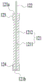
FIG. 14 is a schematic view of a second pole piece 12 in an expanded state according to an embodiment of the present application; fig. 15 is a schematic cross-sectional view of the second pole piece 12 shown in fig. 14 taken along the line E-E.
As shown in fig. 14 and 15, in the expanded state, the second pole piece 12 extends in the longitudinal direction thereof. In some embodiments, the second insulating part 123 may be a plurality of parts, and the plurality of second insulating parts 123 and the plurality of second tabs 122 are alternately arranged along the length direction of the second pole piece 12. Each second insulating portion 123 covers a part of the second end portion 121 a.
In some embodiments, there is one fourth insulating portion 124, and the fourth insulating portion 124 completely covers the fourth end portion 121 b.
FIG. 16 is a schematic front view of another electrode assembly 10 according to one embodiment of the present application; fig. 17 is a schematic cross-sectional view of the electrode assembly 10 shown in fig. 16 taken along line F-F.
As shown in fig. 16 and 17, in some embodiments, the second pole ear 122 is connected to the fourth end 121 b. The third insulating part 114 can separate the second tab 122 from the third end part 111b when the second tab 122 is bent, thereby reducing the risk of the second tab 122 contacting the first body part 111 and improving the safety of the electrode assembly 10. When the second pole ear 122 is inserted between the first body part 111 and the second body part 121, the third insulating part 114 can also reduce the risk of the second pole ear 122 contacting the first body part 111, and improve the safety performance.
While the present application has been described with reference to preferred embodiments, various modifications may be made and equivalents may be substituted for elements thereof without departing from the scope of the present application, and in particular, features shown in the various embodiments may be combined in any manner as long as there is no structural conflict. The present application is not intended to be limited to the particular embodiments disclosed herein but is to cover all embodiments that may fall within the scope of the appended claims.
Claims (15)
1. An electrode assembly, comprising:
the first pole piece comprises a first main body part and a first pole lug, the first main body part is provided with a first end part in a first direction, and the first pole lug is connected to the first end part;
the second pole piece comprises a second main body part and a second insulating part connected to the second main body part, the first main body part and the second main body part are arranged in a stacked mode, the stacking direction of the first main body part and the second main body part is perpendicular to the first direction, the second main body part is provided with a second end part close to the first tab in the first direction, and the second insulating part at least covers one part of the second end part so as to separate the first tab from the second end part when the first tab is bent.
2. The electrode assembly according to claim 1, wherein the second insulating portion includes a second covering region provided on one side of the second main body portion in the first direction and covering at least a portion of the second end portion, and a second connecting region connected to the second covering region, the second connecting region being connected to the second main body portion;
the second connection region is at least partially located between the first and second body portions to separate the second body portion and the first tab when the first tab is inserted between the first and second body portions.
3. The electrode assembly according to claim 2, wherein the second connection regions are provided in two and are respectively provided on both sides of the second main body portion in the stacking direction.
4. The electrode assembly according to claim 2, wherein a ratio of a dimension of the second connection region in the first direction to a dimension of the second main body portion in the first direction is 0.5% to 6%.
5. The electrode assembly of claim 2,
the first pole piece further comprises a first insulating portion, the first insulating portion comprises a first covering area and a first connecting area connected to the first covering area, and the first covering area is arranged on one side of the first main body portion along the first direction and covers at least part of the first end portion;
the first connection region is at least partially located between and connected to the first body portion and the second body portion.
6. The electrode assembly of claim 5,
the first pole piece is a positive pole piece, and the second pole piece is a negative pole piece;
in a direction facing away from the first tab and parallel to the first direction, an edge of the second connection region facing away from the second footprint does not exceed an edge of the first connection region facing away from the first footprint.
7. The electrode assembly of claim 6, wherein an edge of the second connection region facing away from the second footprint area is spaced from an edge of the first connection region facing away from the first footprint area by more than 0.05mm in a direction facing away from the first tab and parallel to the first direction.
8. The electrode assembly of claim 6,
the first main body part comprises a first current collecting area, a first active material layer and a first protective layer, the first active material layer is coated on the surface of the first current collecting area, and the first protective layer is coated on the surface of the first current collecting area and connected to the first active material layer;
the first protective layer is positioned on one side, close to the first tab, of the first active material layer along the first direction;
the first connecting area is fixed to the first protection layer, and in a direction which deviates from the first tab and is parallel to the first direction, the edge of the first connecting area which deviates from the first coverage area does not exceed the first protection layer.
9. The electrode assembly of any one of claims 5-8,
the first body portion has a third end facing away from the first end in the first direction, and the second body portion has a fourth end facing away from the second end in the first direction;
the second pole piece further comprises a second pole tab connected to the second end or the fourth end.
10. The electrode assembly of claim 9,
the first pole piece further comprises a third insulating part which is connected to the first main body part and at least covers a part of the third end part; and/or
The second pole piece further includes a fourth insulating portion connected to the second main body portion and covering at least a portion of the fourth end portion.
11. The electrode assembly of claim 1, wherein the second insulating portion has a pore structure for metal ions to pass through.
12. The electrode assembly of claim 1, further comprising a separator for separating the first and second pole pieces;
the second insulating portion has a thickness greater than that of the isolation film.
13. A battery cell, comprising:
a housing having an accommodating chamber and an opening;
at least one electrode assembly as set forth in any one of claims 1-12 received in said receiving cavity; and
and the cover plate is used for closing the opening of the shell.
14. A battery, comprising:
a box body;
at least one cell according to claim 13, said cell being housed in said case.
15. An electrical device, wherein the electrical device is configured to receive power provided from the battery of claim 14.
Priority Applications (6)
| Application Number | Priority Date | Filing Date | Title |
|---|---|---|---|
| CN202023344172.0U CN214254666U (en) | 2020-12-31 | 2020-12-31 | Electrode assembly, battery cell, battery, and power consumption device |
| KR1020227038354A KR20220162780A (en) | 2020-12-31 | 2021-10-29 | Electrode assemblies, battery cells, batteries and electrical devices |
| EP21913437.6A EP4131631A4 (en) | 2020-12-31 | 2021-10-29 | Electrode assembly, battery cell, battery and power-consuming apparatus |
| PCT/CN2021/127714 WO2022142693A1 (en) | 2020-12-31 | 2021-10-29 | Electrode assembly, battery cell, battery and power-consuming apparatus |
| JP2022567035A JP2023527676A (en) | 2020-12-31 | 2021-10-29 | Electrode components, battery cells, batteries and power consumers |
| US18/159,684 US20230170592A1 (en) | 2020-12-31 | 2023-01-26 | Electrode assembly, battery cell, battery, and electric apparatus |
Applications Claiming Priority (1)
| Application Number | Priority Date | Filing Date | Title |
|---|---|---|---|
| CN202023344172.0U CN214254666U (en) | 2020-12-31 | 2020-12-31 | Electrode assembly, battery cell, battery, and power consumption device |
Publications (1)
| Publication Number | Publication Date |
|---|---|
| CN214254666U true CN214254666U (en) | 2021-09-21 |
Family
ID=77723558
Family Applications (1)
| Application Number | Title | Priority Date | Filing Date |
|---|---|---|---|
| CN202023344172.0U Active CN214254666U (en) | 2020-12-31 | 2020-12-31 | Electrode assembly, battery cell, battery, and power consumption device |
Country Status (6)
| Country | Link |
|---|---|
| US (1) | US20230170592A1 (en) |
| EP (1) | EP4131631A4 (en) |
| JP (1) | JP2023527676A (en) |
| KR (1) | KR20220162780A (en) |
| CN (1) | CN214254666U (en) |
| WO (1) | WO2022142693A1 (en) |
Cited By (5)
| Publication number | Priority date | Publication date | Assignee | Title |
|---|---|---|---|---|
| CN114122327A (en) * | 2022-01-29 | 2022-03-01 | 宁德时代新能源科技股份有限公司 | Pole piece and secondary battery with same |
| WO2022142693A1 (en) * | 2020-12-31 | 2022-07-07 | 宁德时代新能源科技股份有限公司 | Electrode assembly, battery cell, battery and power-consuming apparatus |
| WO2023130278A1 (en) * | 2022-01-05 | 2023-07-13 | 宁德时代新能源科技股份有限公司 | Electrode assembly and preparation method therefor, battery cell, battery, and electronic device |
| WO2023225903A1 (en) * | 2022-05-25 | 2023-11-30 | 宁德时代新能源科技股份有限公司 | Battery cell, battery, and electrical device |
| WO2024000163A1 (en) * | 2022-06-28 | 2024-01-04 | 宁德时代新能源科技股份有限公司 | Electrode sheet, electrode assembly, battery cell, battery and electric device |
Family Cites Families (8)
| Publication number | Priority date | Publication date | Assignee | Title |
|---|---|---|---|---|
| JP4366783B2 (en) * | 1998-11-16 | 2009-11-18 | 株式会社デンソー | Multilayer battery and method of manufacturing electrode thereof |
| EP1278253B1 (en) * | 2001-07-19 | 2013-05-08 | Greatbatch Ltd. | Insulative component for an electrochemical cell |
| JP4201619B2 (en) * | 2003-02-26 | 2008-12-24 | 三洋電機株式会社 | Nonaqueous electrolyte secondary battery and method for producing electrode used therefor |
| WO2016067706A1 (en) * | 2014-10-27 | 2016-05-06 | Necエナジーデバイス株式会社 | Method for producing electrode for secondary battery, electrode for secondary battery, and secondary battery |
| US10115997B2 (en) * | 2016-05-12 | 2018-10-30 | Bosch Battery Systems Llc | Prismatic electrochemical cell |
| US11128019B2 (en) * | 2016-11-04 | 2021-09-21 | Gs Yuasa International Ltd. | Energy storage device electrode, energy storage device, and method for manufacturing energy storage device electrode |
| CN210535760U (en) * | 2019-08-14 | 2020-05-15 | 宁德时代新能源科技股份有限公司 | Electrode assembly and secondary battery |
| CN214254666U (en) * | 2020-12-31 | 2021-09-21 | 宁德时代新能源科技股份有限公司 | Electrode assembly, battery cell, battery, and power consumption device |
-
2020
- 2020-12-31 CN CN202023344172.0U patent/CN214254666U/en active Active
-
2021
- 2021-10-29 KR KR1020227038354A patent/KR20220162780A/en unknown
- 2021-10-29 WO PCT/CN2021/127714 patent/WO2022142693A1/en unknown
- 2021-10-29 JP JP2022567035A patent/JP2023527676A/en active Pending
- 2021-10-29 EP EP21913437.6A patent/EP4131631A4/en active Pending
-
2023
- 2023-01-26 US US18/159,684 patent/US20230170592A1/en active Pending
Cited By (6)
| Publication number | Priority date | Publication date | Assignee | Title |
|---|---|---|---|---|
| WO2022142693A1 (en) * | 2020-12-31 | 2022-07-07 | 宁德时代新能源科技股份有限公司 | Electrode assembly, battery cell, battery and power-consuming apparatus |
| WO2023130278A1 (en) * | 2022-01-05 | 2023-07-13 | 宁德时代新能源科技股份有限公司 | Electrode assembly and preparation method therefor, battery cell, battery, and electronic device |
| CN114122327A (en) * | 2022-01-29 | 2022-03-01 | 宁德时代新能源科技股份有限公司 | Pole piece and secondary battery with same |
| WO2023142340A1 (en) * | 2022-01-29 | 2023-08-03 | 宁德时代新能源科技股份有限公司 | Electrode plate, and secondary battery comprising same |
| WO2023225903A1 (en) * | 2022-05-25 | 2023-11-30 | 宁德时代新能源科技股份有限公司 | Battery cell, battery, and electrical device |
| WO2024000163A1 (en) * | 2022-06-28 | 2024-01-04 | 宁德时代新能源科技股份有限公司 | Electrode sheet, electrode assembly, battery cell, battery and electric device |
Also Published As
| Publication number | Publication date |
|---|---|
| WO2022142693A1 (en) | 2022-07-07 |
| US20230170592A1 (en) | 2023-06-01 |
| EP4131631A4 (en) | 2023-12-20 |
| KR20220162780A (en) | 2022-12-08 |
| EP4131631A1 (en) | 2023-02-08 |
| JP2023527676A (en) | 2023-06-30 |
Similar Documents
| Publication | Publication Date | Title |
|---|---|---|
| CN214254666U (en) | Electrode assembly, battery cell, battery, and power consumption device | |
| CN213692108U (en) | Electrode assembly, battery cell, battery, and power consumption device | |
| EP4243166A1 (en) | End cover assembly, battery cell, battery and electrical device | |
| CN216389437U (en) | Current collecting component, battery monomer, battery and electric equipment | |
| CN215989141U (en) | Battery cell, battery and power consumption device | |
| CN216213945U (en) | Battery cell, battery and power consumption device | |
| US20230216154A1 (en) | Current collecting member, battery cell, battery, and power consuming device | |
| EP4266479A1 (en) | Battery cell, battery and power consuming device | |
| CN212161993U (en) | Electrode assembly, battery module, battery pack, device using battery, and device for manufacturing electrode assembly | |
| WO2024045692A1 (en) | Battery module, battery and electric device | |
| US20230087166A1 (en) | Electrode assembly, battery cell, battery and electrical device | |
| CN217768626U (en) | Battery cell, battery and power consumption device | |
| CN218414686U (en) | Battery cell, battery and power consumption device | |
| CN114503334A (en) | Electrode assembly and related battery, device, manufacturing method and manufacturing device thereof | |
| CN217788704U (en) | Battery cell, battery and consumer | |
| CN115064757B (en) | Battery cell, battery and power consumption device | |
| CN217158410U (en) | Battery cell, battery and power consumption device | |
| CN216872125U (en) | Battery cell, battery and consumer | |
| CN213692221U (en) | Battery cell, battery and power consumption device | |
| CN219144431U (en) | Electrode assembly, battery cell, battery and electricity utilization device | |
| CN218827461U (en) | Battery cell's shell, battery cell, battery and consumer | |
| CN220400841U (en) | Battery connection tab, battery and electricity utilization device | |
| CN220569821U (en) | Battery monomer, battery and power consumption device | |
| WO2023173414A1 (en) | Battery cell and manufacturing method and manufacturing system therefor, battery, and electrical device | |
| WO2023225903A1 (en) | Battery cell, battery, and electrical device |
Legal Events
| Date | Code | Title | Description |
|---|---|---|---|
| GR01 | Patent grant | ||
| GR01 | Patent grant |