EP4273748B1 - Bake und landeverfahren für unbemanntes flugzeug - Google Patents
Bake und landeverfahren für unbemanntes flugzeug Download PDFInfo
- Publication number
- EP4273748B1 EP4273748B1 EP22832133.7A EP22832133A EP4273748B1 EP 4273748 B1 EP4273748 B1 EP 4273748B1 EP 22832133 A EP22832133 A EP 22832133A EP 4273748 B1 EP4273748 B1 EP 4273748B1
- Authority
- EP
- European Patent Office
- Prior art keywords
- code
- level
- pattern
- candidate
- target
- Prior art date
- Legal status (The legal status is an assumption and is not a legal conclusion. Google has not performed a legal analysis and makes no representation as to the accuracy of the status listed.)
- Active
Links
Images



Classifications
-
- B—PERFORMING OPERATIONS; TRANSPORTING
- B64—AIRCRAFT; AVIATION; COSMONAUTICS
- B64F—GROUND OR AIRCRAFT-CARRIER-DECK INSTALLATIONS SPECIALLY ADAPTED FOR USE IN CONNECTION WITH AIRCRAFT; DESIGNING, MANUFACTURING, ASSEMBLING, CLEANING, MAINTAINING OR REPAIRING AIRCRAFT, NOT OTHERWISE PROVIDED FOR; HANDLING, TRANSPORTING, TESTING OR INSPECTING AIRCRAFT COMPONENTS, NOT OTHERWISE PROVIDED FOR
- B64F1/00—Ground or aircraft-carrier-deck installations
- B64F1/18—Visual or acoustic landing aids
-
- G—PHYSICS
- G05—CONTROLLING; REGULATING
- G05D—SYSTEMS FOR CONTROLLING OR REGULATING NON-ELECTRIC VARIABLES
- G05D1/00—Control of position, course, altitude or attitude of land, water, air or space vehicles, e.g. using automatic pilots
- G05D1/04—Control of altitude or depth
- G05D1/06—Rate of change of altitude or depth
- G05D1/0607—Rate of change of altitude or depth specially adapted for aircraft
- G05D1/0653—Rate of change of altitude or depth specially adapted for aircraft during a phase of take-off or landing
- G05D1/0676—Rate of change of altitude or depth specially adapted for aircraft during a phase of take-off or landing specially adapted for landing
-
- G—PHYSICS
- G06—COMPUTING OR CALCULATING; COUNTING
- G06K—GRAPHICAL DATA READING; PRESENTATION OF DATA; RECORD CARRIERS; HANDLING RECORD CARRIERS
- G06K19/00—Record carriers for use with machines and with at least a part designed to carry digital markings
- G06K19/06—Record carriers for use with machines and with at least a part designed to carry digital markings characterised by the kind of the digital marking, e.g. shape, nature, code
- G06K19/06009—Record carriers for use with machines and with at least a part designed to carry digital markings characterised by the kind of the digital marking, e.g. shape, nature, code with optically detectable marking
- G06K19/06037—Record carriers for use with machines and with at least a part designed to carry digital markings characterised by the kind of the digital marking, e.g. shape, nature, code with optically detectable marking multi-dimensional coding
-
- G—PHYSICS
- G06—COMPUTING OR CALCULATING; COUNTING
- G06K—GRAPHICAL DATA READING; PRESENTATION OF DATA; RECORD CARRIERS; HANDLING RECORD CARRIERS
- G06K19/00—Record carriers for use with machines and with at least a part designed to carry digital markings
- G06K19/06—Record carriers for use with machines and with at least a part designed to carry digital markings characterised by the kind of the digital marking, e.g. shape, nature, code
- G06K19/06009—Record carriers for use with machines and with at least a part designed to carry digital markings characterised by the kind of the digital marking, e.g. shape, nature, code with optically detectable marking
- G06K19/06046—Constructional details
-
- G—PHYSICS
- G06—COMPUTING OR CALCULATING; COUNTING
- G06K—GRAPHICAL DATA READING; PRESENTATION OF DATA; RECORD CARRIERS; HANDLING RECORD CARRIERS
- G06K19/00—Record carriers for use with machines and with at least a part designed to carry digital markings
- G06K19/06—Record carriers for use with machines and with at least a part designed to carry digital markings characterised by the kind of the digital marking, e.g. shape, nature, code
- G06K19/06009—Record carriers for use with machines and with at least a part designed to carry digital markings characterised by the kind of the digital marking, e.g. shape, nature, code with optically detectable marking
- G06K19/06046—Constructional details
- G06K19/0614—Constructional details the marking being selective to wavelength, e.g. color barcode or barcodes only visible under UV or IR
-
- G—PHYSICS
- G08—SIGNALLING
- G08G—TRAFFIC CONTROL SYSTEMS
- G08G5/00—Traffic control systems for aircraft
- G08G5/20—Arrangements for acquiring, generating, sharing or displaying traffic information
- G08G5/22—Arrangements for acquiring, generating, sharing or displaying traffic information located on the ground
-
- G—PHYSICS
- G08—SIGNALLING
- G08G—TRAFFIC CONTROL SYSTEMS
- G08G5/00—Traffic control systems for aircraft
- G08G5/50—Navigation or guidance aids
- G08G5/54—Navigation or guidance aids for approach or landing
-
- G—PHYSICS
- G08—SIGNALLING
- G08G—TRAFFIC CONTROL SYSTEMS
- G08G5/00—Traffic control systems for aircraft
- G08G5/50—Navigation or guidance aids
- G08G5/55—Navigation or guidance aids for a single aircraft
-
- G—PHYSICS
- G08—SIGNALLING
- G08G—TRAFFIC CONTROL SYSTEMS
- G08G5/00—Traffic control systems for aircraft
- G08G5/50—Navigation or guidance aids
- G08G5/57—Navigation or guidance aids for unmanned aircraft
-
- B—PERFORMING OPERATIONS; TRANSPORTING
- B64—AIRCRAFT; AVIATION; COSMONAUTICS
- B64U—UNMANNED AERIAL VEHICLES [UAV]; EQUIPMENT THEREFOR
- B64U70/00—Launching, take-off or landing arrangements
- B64U70/90—Launching from or landing on platforms
- B64U70/95—Means for guiding the landing UAV towards the platform, e.g. lighting means
-
- B—PERFORMING OPERATIONS; TRANSPORTING
- B64—AIRCRAFT; AVIATION; COSMONAUTICS
- B64U—UNMANNED AERIAL VEHICLES [UAV]; EQUIPMENT THEREFOR
- B64U70/00—Launching, take-off or landing arrangements
- B64U70/90—Launching from or landing on platforms
- B64U70/97—Means for guiding the UAV to a specific location on the platform, e.g. platform structures preventing landing off-centre
-
- G—PHYSICS
- G06—COMPUTING OR CALCULATING; COUNTING
- G06K—GRAPHICAL DATA READING; PRESENTATION OF DATA; RECORD CARRIERS; HANDLING RECORD CARRIERS
- G06K19/00—Record carriers for use with machines and with at least a part designed to carry digital markings
- G06K19/06—Record carriers for use with machines and with at least a part designed to carry digital markings characterised by the kind of the digital marking, e.g. shape, nature, code
- G06K19/06009—Record carriers for use with machines and with at least a part designed to carry digital markings characterised by the kind of the digital marking, e.g. shape, nature, code with optically detectable marking
- G06K19/06046—Constructional details
- G06K19/06056—Constructional details the marking comprising a further embedded marking, e.g. a 1D bar code with the black bars containing a smaller sized coding
-
- G—PHYSICS
- G06—COMPUTING OR CALCULATING; COUNTING
- G06K—GRAPHICAL DATA READING; PRESENTATION OF DATA; RECORD CARRIERS; HANDLING RECORD CARRIERS
- G06K19/00—Record carriers for use with machines and with at least a part designed to carry digital markings
- G06K19/06—Record carriers for use with machines and with at least a part designed to carry digital markings characterised by the kind of the digital marking, e.g. shape, nature, code
- G06K2019/06215—Aspects not covered by other subgroups
- G06K2019/06225—Aspects not covered by other subgroups using wavelength selection, e.g. colour code
-
- G—PHYSICS
- G06—COMPUTING OR CALCULATING; COUNTING
- G06K—GRAPHICAL DATA READING; PRESENTATION OF DATA; RECORD CARRIERS; HANDLING RECORD CARRIERS
- G06K19/00—Record carriers for use with machines and with at least a part designed to carry digital markings
- G06K19/06—Record carriers for use with machines and with at least a part designed to carry digital markings characterised by the kind of the digital marking, e.g. shape, nature, code
- G06K2019/06215—Aspects not covered by other subgroups
- G06K2019/06253—Aspects not covered by other subgroups for a specific application
-
- G—PHYSICS
- G06—COMPUTING OR CALCULATING; COUNTING
- G06K—GRAPHICAL DATA READING; PRESENTATION OF DATA; RECORD CARRIERS; HANDLING RECORD CARRIERS
- G06K19/00—Record carriers for use with machines and with at least a part designed to carry digital markings
- G06K19/06—Record carriers for use with machines and with at least a part designed to carry digital markings characterised by the kind of the digital marking, e.g. shape, nature, code
- G06K2019/06215—Aspects not covered by other subgroups
- G06K2019/06262—Aspects not covered by other subgroups with target- or other orientation-indicating feature
Definitions
- Embodiments of this application relate to the technical field of unmanned aerial vehicles, and in particular to a beacon and a landing method for an unmanned aerial vehicle.
- US20210031945A1 discloses a target member for accurately guiding a moving body to a target site.
- a target member is used when performing control for guiding a moving body to a target site, and the target member is formed by using two or more different feature members that are set such that a shape of a target member image that corresponds to the target member captured by an image capturing unit that is mounted in the moving body changes according to a measurement distance that indicates a distance between the target member and the moving body.
- US20160124431A1 discloses a multi-scale fiducial, which may have three or more scales, where the child fiducials are nested or otherwise linked by a relative position to the parent fiducials.
- Multi-scale fiducials may facilitate target identification and tracking at varying distances, potentially without the aid of a scale-invariant recognition algorithm.
- One application of multi-scale fiducials may involve target identification for autonomously controlled aerial vehicles.
- CN106127201A discloses a vision localization landing tail end-based unmanned aerial vehicle landing method.
- a used unmanned aerial vehicle airport consists of a plurality of gate position Markers; each unmanned aerial vehicle obtains Markers in a visual range through a visual module and verifies the ID of each Marker in the visual range, so as to estimate the own position to land accurately.
- Embodiments of this application provide a beacon and a landing method for an unmanned aerial vehicle.
- the technical solution is as follows:
- An embodiment of this application provides a beacon in accordance with independent claim 1.
- the beacon includes one first-level pattern, four second-level patterns and five third-level patterns, an area of the second-level pattern is less than that of the first-level pattern, and an area of the third-level pattern is less than that of the second-level pattern, wherein:
- the first-level pattern is obtained based on a reference code
- the second-level pattern is obtained based on a second-level code
- the third-level pattern is obtained based on a third-level code
- An embodiment of this application provides a landing method for an unmanned aerial vehicle, including: recognizing any above beacon, adjusting a descent speed and descent direction of the unmanned aerial vehicle based on the recognized beacon, such that the unmanned aerial vehicle lands at a preset position.
- a beacon is placed at the preset position and consists of a first-level pattern and second-level patterns (at least one second-level pattern is nested in one first-level pattern).
- a flight altitude of the unmanned aerial vehicle indicated by the first-level pattern is larger than a flight altitude of the unmanned aerial vehicle indicated by the second-level patterns.
- the unmanned aerial vehicle in the air may land at the preset position by adjusting a descent speed and a descent direction based on a recognized beacon.
- the beacon patterns are likely to be stained due to long-term exposure, and the beacon patterns may be inaccurately recognized or cannot be recognized due to external environments such as shadows generated by surrounding objects shielding sunlight, which causes difficulty in accurate landing of the unmanned aerial vehicle.
- the difference in area of the first-level pattern and the second-level patterns is also a challenging aspect in design, and improper processing/design of the area of the first-level pattern and the second-level patterns is likely to cause the problem of inaccurate landing regardless of a large difference or a small difference.
- the beacon generation method is provided by embodiments of this application to generate a high-reliability beacon for guiding the unmanned aerial vehicle to accurately land.
- FIG. 1 is a schematic diagram showing an implementation environment of a beacon generation method according to an embodiment of this application, but not according to the claims.
- the implementation environment includes: a computer device 101.
- the computer device 101 may be an electronic device, or a server, which is not limited by this embodiment of this application.
- the computer device 101 is configured to execute the beacon generation method provided by this embodiment of this application.
- the electronic device may be at least one of a smart phone, a game console, a desk computer, a tablet, an ebook reader, a moving picture experts group audio layer III (MP3) player, a moving picture experts group audio layer IV (MP4) player and a laptop.
- a smart phone a game console
- a desk computer a tablet
- an ebook reader a moving picture experts group audio layer III (MP3) player
- MP4 moving picture experts group audio layer IV
- the server may be one server or a server cluster composed of a plurality of servers, or any one of a cloud computing platform and a virtualization center, which is not limited by this embodiment of this application.
- the server may be in communication connection with the electronic device through a wired network or a wireless network.
- the server may have functions of data processing, data storage and data receiving and transmitting.
- the server may also have other functions, which is not limited by this embodiment of this application.
- this embodiment of this application provides the beacon generation method.
- the method may be executed by the computer device 101 in FIG. 1 .
- the method includes following steps: Step 201: A first-level code is acquired.
- the process of acquiring the first-level code is as follows: a random number code is acquired, and processed based on a second distance to obtain at least one second code, and the first-level code is determined in the random number code and the at least one second code.
- the at least one second code and the random number code are consistent in number of digits, and a distance between any two of the at least one second code and the random number code is not less than the second distance.
- the random number code includes a first digit and a second digit, and may be determined by a user, or automatically generated by the computer device based on a random number generator, which is not limited by this embodiment of this application.
- the first digit and the second digit may be any two different digits, which is not limited by this embodiment of this application.
- the first digit is 0, and the second digit is 1.
- the second distance is set by the user, or adjusted according to the application scenario, and the second distance is any distance greater than zero and less than the number of digits of the random number code, and this embodiment of this application does not limit the second distance.
- the number of digits of the random number code is not less than 4.
- the number of digits of the random number code is 16, and the second distance is 5.
- the random number code is 16 digits long, and the random number code is 1010010100000011.
- a distance between the second code and the random number code may be the Hamming distance, or other distances, which is not limited by this embodiment of this application.
- This embodiment of this application illustrates the distance by the Hamming distance.
- the Hamming distance is used in data transmission error control coding, and is a concept used for representing the number of different corresponding bits between two codes identical in length.
- the Hamming distance determining process is as follows: xor (exclusive or) operation is performed on the two codes, the number of digit 1 in a result is counted, and the number of 1s in the result is the Hamming distance between the two codes.
- the random number code is processed based on the second distance.
- the process of obtaining the at least one second code includes following step 2011 to step 2014.
- Step 2011 A first target code is acquired based on the random number code and is consistent to the random number code in number of digits, and a distance between the first target code and the random number code is not less than the second distance.
- the random number code after the random number code is acquired, digits included in the random number code are modified to obtain the first target code, the first target code is consistent to the random number code in number of digits, and the distance between the first target code and the random number code is not less than the second distance.
- the second distance is 5
- the random number code is 1010010100000011
- the random number code is processed to obtain the first target code 1010110101101111.
- the first target code is consistent to the random number code in number of digits, and the distance between the first target code and the random number code is 5.
- Step 2012 At least one second target code is acquired based on the first target code, and the second target code is consistent to the first target code in number of digits.
- the process of acquiring at least one second target code based on the first target code is as follows: an intermediate pattern corresponding to the first target code is generated. First rotation transformation is performed on the intermediate pattern corresponding to the first target code to obtain at least one first target pattern. A code respectively corresponding to each of the at least one first target pattern is acquired. The code respectively corresponding to each of the at least one first target pattern serves as a second target code.
- a first rotation transformation angle includes at least one of 90 degrees, 180 degrees and 270 degrees.
- the process of generating an intermediate pattern corresponding to the first target code is as follows: a target pattern is acquired based on the number of digits of the first target code, and is composed of grids, and the number of the grids included in the target pattern is consistent to the number of digits of the first target code. Digits included in the first target code are filled into the target pattern according to a target sequence, such that an intermediate pattern corresponding to the first target code is obtained.
- the target sequence may be a sequence from left to right and then from top to bottom, or may be a sequence from top to bottom and then from left to right, or may be other sequences, which is not limited by this embodiment of this application.
- FIG. 3 illustrates a schematic diagram of an intermediate pattern corresponding to a first target code according to an embodiment of this application, but not according to the claims.
- a figure A in FIG. 3 is a target pattern, and the target pattern is composed of 16 grids. Digits included in the first target code are filled into the target pattern according to a target sequence (from left to right and then from top to bottom), such that an intermediate pattern corresponding to the first target code is obtained, and a figure B in FIG. 3 is the intermediate pattern corresponding to the first target code.
- first rotation transformation is performed on the intermediate pattern corresponding to the first target code to obtain one first target pattern.
- first rotation transformation angle includes any two of 90 degrees, 180 degrees and 270 degrees
- first rotation transformation is performed on the intermediate pattern corresponding to the first target code to obtain two first target patterns.
- first rotation transformation angle includes 90 degrees, 180 degrees and 270 degrees
- first rotation transformation is performed on the intermediate pattern corresponding to the first target code to obtain three first target patterns.
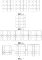
- FIG. 4 illustrates a schematic diagram of a first target pattern according to an embodiment of this application, but not according to the claims.
- a figure A in FIG. 4 is a first target pattern obtained by rotating an intermediate pattern corresponding to a first target code by 90 degrees.
- a figure B in FIG. 4 is a first target pattern obtained by rotating the intermediate pattern corresponding to the first target code by 180 degrees.
- a figure C in FIG. 4 is a first target pattern obtained by rotating the intermediate pattern corresponding to the first target code by 270 degrees.
- the process of acquiring a code respectively corresponding to each of the at least one first target pattern is as follows: digits included in each first target pattern are extracted according to a target sequence, and a code corresponding to each first target pattern is obtained.
- the target sequence is a sequence from left to right and then from top to bottom, digits in the first target pattern are extracted according to the sequence, and a code corresponding to the first target pattern is obtained.
- a code corresponding to the first target pattern obtained by rotating the intermediate pattern corresponding to the first target code by 90 degrees is 1011111011011010.
- a code corresponding to the first target pattern obtained by rotating the intermediate pattern corresponding to the first target code by 180 degrees is 1111011010110101.
- a code corresponding to the first target pattern obtained by rotating the intermediate pattern corresponding to the first target code by 270 degrees is 0101101101111101.
- the code corresponding to each first target pattern is acquired, the code corresponding to each first target pattern is determined as a second target code, that is, the second target codes are: 1011111011011010, 1111011010110101, and 0101101101111101.
- Step 2013 In response to the distance between the at least one second target code and the first target code being not less than the second distance, at least one third target code is acquired based on the random number code.
- the distance between each second target code and the first target code is determined.
- the process of determining the distance between each second target code and the first target code is as follows: xor operation is performed on the first target code and the second target code, the number of 1s in a result is counted, and the number of 1s in the result is determined as the Hamming distance between the first target code and the second target code.
- the distance between the first target code and the second target code is determined through following Table 1.
- Table 1 First target code 1 0 1 0 1 1 0 1 0 1 1 0 1 1 1 1 1 1 1 0 1 1 0 1 0 Xor operation result 0 0 0 1 0 0 1 1 1 0 1 1 0 1 0 1 0 1 0 1 Hamming distance 8
- the number of 1s in an obtained result is 8, that is, the Hamming distance between the first target code and the second target code is 8.
- the distance between each second target code and the first target code is required to be determined, and the process of determining the distance between each second target code and the first target code is similar to the process of determining the distance between the first target code and the second target code in Table 1, which is not repeated herein.
- the second target code is a code obtained by performing first rotation transformation on the intermediate pattern corresponding to the first target code, in response to the distance between the first target code and the at least one second target code being not less than the second distance, it is indicated that the first target code has large difference and contrast, and low similarity with itself.
- the process of acquiring at least one third target code based on the random number code is as follows: in response to the distance between the at least one second target code and the first target code being not less than the second distance and the first target code being a first target code acquired based on the random number code, at least one third target code is acquired based on the random number code. In response to the distance between the at least one second target code and the first target code being not less than the second distance, and the first target code being not a first target code acquired based on the random number code, at least one third target code is acquired based on the random number code and a target code acquired before the first target code. The third target code is consistent to the random number code in number of digits.
- the process of acquiring at least one third target code based on the random number code is similar to the process of acquiring at least one third target code based on the random number code and a target code acquired before the first target code, and this embodiment of this application only illustrates the process of acquiring at least one third target code based on the random number code.
- the process of acquiring at least one third target code based on the random number code is as follows: an intermediate pattern corresponding to the random number code is generated. Second rotation transformation is performed on the intermediate pattern corresponding to the random number code to obtain at least one second target pattern. A code respectively corresponding to each of the at least one second target pattern is acquired. The code respectively corresponding to each of the at least one second target pattern serves as a third target code.
- a second rotation transformation angle includes at least one of 0 degree, 90 degrees, 180 degrees and 270 degrees.
- FIG. 5 illustrates a schematic diagram of an intermediate pattern corresponding to a random number code according to an embodiment of this application, but not according to the claims.
- FIG. 6 illustrates a schematic diagram of a second target pattern according to an embodiment of this application, but not according to the claims.
- a figure A in FIG. 6 is a second target pattern obtained by rotating the intermediate pattern corresponding to the random number code by 0 degree
- a figure B in FIG. 6 is a second target pattern obtained by rotating the intermediate pattern corresponding to the random number code by 90 degrees
- a figure C in FIG. 6 is a second target pattern obtained by rotating the intermediate pattern corresponding to the random number code by 180 degrees
- a figure D in FIG. 6 is a second target pattern obtained by rotating the intermediate pattern corresponding to the random number code by 270 degrees.
- the process of acquiring a code respectively corresponding to each of the at least one second target pattern is as follows: digits included in each second target pattern are extracted according to a target sequence, and a code respectively corresponding to each second target pattern is obtained.
- the target sequence is a sequence from left to right and then from top to bottom, the digits in the second target pattern are extracted according to the target sequence, and a code corresponding to the second target pattern is obtained.
- the code corresponding to the second target pattern obtained by rotating the intermediate pattern corresponding to the random number code by 0 degree is consistent to the random number code.
- a code corresponding to the second target pattern obtained by rotating the intermediate pattern corresponding to the random number code by 90 degrees is 0001001010011010.
- a code corresponding to the second target pattern obtained by rotating the intermediate pattern corresponding to the random number code by 180 degrees is 1100000010100101.
- a code corresponding to the second target pattern obtained by rotating the intermediate pattern corresponding to the random number code by 270 degrees is 0101100101001000.
- the code corresponding to each second target pattern is acquired, the code corresponding to each second target pattern is determined as a third target code, that is, the third target codes are: 1010010100000011, 0001001010011010, 1100000010100101, and 0101100101001000
- step 2011 in response to a second target code in at least one second target code spaced from the first target code by a distance less than the second distance, there is no need to perform subsequent steps, and return to step 2011 to re-acquire a first target code based on the random number code.
- the number of the third target codes acquired based on the random number code is less than the number of the third target codes acquired based on the random number code and the target code acquired before the first target code.
- Step 2014 In response to the distance between the at least one third target code and the first target code being not less than the second distance, the first target code serves as a second code.
- the distance between the third target code and the first target code is determined, and the process of determining the distance between the third target code and the first target code is consistent to the process of determining the distance between the second target code and the first target code in step 2013, which is not repeated herein.
- the third target code is the code obtained by performing second rotation transformation on the generated code, and in response to the distance between the first target code and the at least one third target code being not less than the second distance, it is indicated that the first target code and other generated codes are large in difference and contrast, and low in similarity.
- step 2011 in response to a third target code in at least one third target code spaced from the first target code by a distance less than the second distance, return to step 2011 to re-acquire a first target code based on the random number code.
- the random number code when the random number code is 16 digits long, and the second distance is 5, 37 second codes satisfying requirements can be generated based on the random number code, and a distance between the random number code and any two of the 37 second codes is not less than 5.
- the number of the acquired second codes is negatively correlated with the second distance.
- the computer device acquires, based on the random number code, second codes by running a formula (1) and a formula (2) as follows: H m 1 t , m 1 k ⁇ ⁇ ⁇ 0 , m 1 k ⁇ A ′ m 1 t H m 1 t , m 1 l ⁇ ⁇ ⁇ 0 , m 1 l ⁇ A m 1 i
- m 1 t denotes a first target code
- m 1 k denotes a second target code
- a ' denotes a first rotation transformation
- ⁇ denotes a second distance
- m 1 k denotes a distance between the first target code and the second target code
- m 1 l denotes a third target code
- A denotes a second rotation transformation
- m 1 i denotes the random number code and a target code acquired before the first target code
- H m 1 t , m 1 l denotes a distance between the first target code and the third target code.
- one of the second code and the random number code is randomly determined as a first-level code.
- the second code and the random number code may also be shown to the user, and the user determines one of the random number code and the second code as the first-level code.
- the random number code serves as the first-level code among the random number code and the at least one second code, that is, the first-level code is 1010010100000011.
- step 202 a reference code is acquired based on the first-level code.
- the first-level code is acquired, digit filling processing is performed on the first-level code to obtain the reference code. Because the first-level code includes a first digit and a second digit, and either of the first digit and the second digit is adopted for filling.
- the process of processing the first-level code to obtain a reference code is as follows: digits included in the first-level code are filled into the target pattern according to a target sequence, such that a pattern corresponding to the first-level code is obtained. A target number of grids are added to the pattern corresponding to the first-level code to obtain a first pattern. Digits are filled into blank grids of the first pattern to obtain an intermediate pattern corresponding to the reference code. Digits included in the intermediate pattern corresponding to the reference code are extracted according to the target sequence to obtain the reference code.
- the target number is any positive integer, which is not limited by this embodiment of this application.
- FIG. 7 illustrates a schematic diagram showing a process of acquiring a reference code according to an embodiment of this application, but not according to the claims.
- a figure A in FIG. 7 is an intermediate pattern corresponding to a first-level code.
- a figure B in FIG. 7 is a first pattern.
- a figure C in FIG. 7 is an intermediate pattern corresponding to the reference code.
- the digits filled into blank grids in the first pattern in FIG. 7 are 1 (the second digit).
- the obtained reference code is: 1011001101111110010000111.
- the reference code is 25 digits long, and the number of digits of the reference code is greater than that of the first-level code.
- 9 grids are added to the middle of the intermediate pattern corresponding to the first-level code in FIG. 7 , and of course, 9 grids may also be added to other positions of the intermediate pattern corresponding to the first-level code, which is not limited by this embodiment of this application.
- step 203 the reference code is processed based on a first distance to obtain at least one first code.
- the process of processing the reference code based on a first distance to obtain at least one first code includes following step 2031 to step 2034.
- Step 2031 A first candidate code is acquired based on the reference code and is consistent to the reference code in number of digits, and a distance between the first candidate code and the reference code is not less than the first distance.
- the first candidate code is consistent to the reference code in number of digits, and the distance between the first candidate code and the reference code is not less than the first distance.
- the distance may be the Hamming distance, or other distances, which is not limited by this embodiment of this application.
- the first distance is a distance greater than zero and less than the number of digits of the reference code, and the first distance and the second distance may be the same or different, which is not limited by this embodiment of this application.
- the first distance is 7.
- the reference code is 1011001101111110010000111, and is processed to obtain the first candidate code 1001011011011011010000111.
- the first candidate code is consistent to the reference code in number of digits, and the distance between the first candidate code and the reference code is 7.
- Step 2032 At least one second candidate code is acquired based on the first candidate code, and the second candidate code is consistent to the first candidate code in number of digits.
- the process of acquiring at least one second candidate code based on the first candidate code is as follows: an intermediate pattern corresponding to the first candidate code is generated. At least one first candidate pattern is obtained by performing first rotation transformation on the intermediate pattern corresponding to the first candidate code. A code respectively corresponding to each of the at least one first candidate pattern is acquired. The code respectively corresponding to each of the at least one first candidate pattern serves as a second candidate code.
- a first rotation transformation angle includes at least one of 90 degrees, 180 degrees and 270 degrees.
- the process of generating an intermediate pattern corresponding to the first candidate code is as follows: a candidate pattern is acquired based on the number of digits of the first candidate code, and is composed of grids, and the number of the grids included in the candidate pattern is consistent to the number of digits of the first candidate code. Digits included in the first candidate code are filled into the candidate pattern according to a target sequence, such that an intermediate pattern corresponding to the first candidate code is obtained.
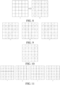
- FIG. 8 illustrates a schematic diagram of an intermediate pattern corresponding to a first candidate code according to an embodiment of this application, but not according to the claims.
- a figure A in FIG. 8 is a candidate pattern, and the candidate pattern is composed of 25 grids. Digits included in the first candidate code are filled into the candidate pattern according to a target sequence, such that the intermediate pattern corresponding to the first candidate code is obtained, and a figure B in FIG. 8 is the intermediate pattern corresponding to the first candidate code.
- first rotation transformation is performed on the intermediate pattern corresponding to the first candidate code to obtain one first candidate pattern.
- first rotation transformation is performed on the intermediate pattern corresponding to the first candidate code to obtain two first candidate patterns.
- first rotation transformation is performed on the intermediate pattern corresponding to the first candidate code to obtain three first candidate patterns.
- FIG. 9 illustrates a schematic diagram of a first candidate pattern according to an embodiment of this application, but not according to the claims.
- a figure A in FIG. 9 is a first candidate pattern obtained by rotating an intermediate pattern corresponding to a first candidate code by 90 degrees.
- a figure B in FIG. 9 is a first candidate pattern obtained by rotating the intermediate pattern corresponding to the first candidate code by 180 degrees.
- a figure C in FIG. 9 is a first candidate pattern obtained by rotating the intermediate pattern corresponding to the first candidate code by 270 degrees.
- the process of acquiring a code respectively corresponding to each of the at least one first candidate pattern is as follows: Digits included in each first candidate pattern are extracted according to a target sequence, and a code corresponding to each first candidate pattern is obtained.
- a code corresponding to the first candidate pattern obtained by rotating the intermediate pattern corresponding to the first candidate code by 90 degrees is 0101100110111001001110110.
- a code corresponding to the first candidate pattern obtained by rotating the intermediate pattern corresponding to the first candidate code by 180 degrees is 1110000101101101101001.
- a code corresponding to the first candidate pattern obtained by rotating the intermediate pattern corresponding to the first candidate code by 270 degrees is 0110111001001110110011010.
- the code corresponding to each first candidate pattern is acquired, the code corresponding to each first candidate pattern is determined as a second candidate code, that is, the second candidate codes are: 0101100110111001001110110, 1110000101101101101001, and 0110111001001110110011010.
- Step 2033 In response to the distance between the at least one second candidate code and the first candidate code being not less than the first distance, at least one third candidate code is acquired based on the reference code and is consistent to the reference code in number of digits.
- the distance between each second candidate code and the first candidate code is determined.
- the process of determining the distance between each second candidate code and the first candidate code is as follows: xor operation is performed on the first candidate code and the second candidate codes, the number of 1s in a result is counted, and the number of 1s in the result is determined as the Hamming distance between the first candidate code and the second candidate codes.
- the distance between the first candidate code and the second candidate code is determined through following Table 2.
- the number of 1s in an obtained result is 14, that is, the Hamming distance between the first candidate code and the second candidate code is 14.
- the distance between each second candidate code and the first candidate code is required to be determined, and the process of determining the distance between each second candidate code and the first candidate code is similar to the process of determining the distance between the first candidate code and the second candidate code in Table 2, which is not repeated herein.
- the second candidate code is a code obtained by performing first rotation transformation on the intermediate pattern corresponding to the first candidate code, in response to the distance between the first candidate code and the at least one second candidate code being not less than the first distance, it is indicated that the first candidate code has large difference and contrast, and low similarity with itself.
- the process of acquiring at least one third candidate code based on the reference code is as follows: in response to the distance between the at least one second candidate code and the first candidate code being not less than the first distance, and the first candidate code being a first candidate code acquired based on the reference code, at least one third candidate code is acquired based on the reference code. In response to the distance between the at least one second candidate code and the first candidate code being not less than the first distance, and the first candidate code being not a first candidate code acquired based on the reference code, at least one third candidate code is acquired based on the reference code and a candidate code acquired before the first candidate code.
- the third candidate code is consistent to the reference code in number of digits.
- the process of acquiring at least one third candidate code based on the reference code is similar to the process of acquiring at least one third candidate code based on the reference code and a candidate code acquired before the first candidate code, and this embodiment of this application only illustrates the process of acquiring at least one third candidate code based on the reference code.
- the process of acquiring at least one third candidate code based on the reference code is as follows: an intermediate pattern corresponding to the reference code is generated. Second rotation transformation is performed on the intermediate pattern corresponding to the reference code to obtain at least one second candidate pattern. A code respectively corresponding to each of the at least one second candidate pattern is acquired. The code respectively corresponding to each of the at least one second candidate pattern serves as a third candidate code.
- a second rotation transformation angle includes at least one of 90 degrees, 180 degrees and 270 degrees.
- FIG. 10 illustrates a schematic diagram of an intermediate pattern corresponding to a reference code according to an embodiment of this application, but not according to the claims.
- FIG. 11 illustrates a schematic diagram of a second candidate pattern according to an embodiment of this application, but not according to the claims.
- a figure A in FIG. 11 is a second candidate pattern obtained by rotating an intermediate pattern corresponding to a reference code by 0 degree.
- a figure B in FIG. 11 is a second candidate pattern obtained by rotating the intermediate pattern corresponding to the reference code by 90 degrees.
- a figure C in FIG. 11 is a second candidate pattern obtained by rotating the intermediate pattern corresponding to the reference code by 180 degrees.
- a figure D in FIG. 11 is a second candidate pattern obtained by rotating the intermediate pattern corresponding to the reference code by 270 degrees.
- the process of acquiring a code respectively corresponding to each of the at least one second candidate pattern is as follows: digits included in each second candidate pattern are extracted according to a target sequence, and a code corresponding to each second candidate pattern is obtained.
- the code corresponding to the second candidate pattern obtained by rotating the intermediate pattern corresponding to the reference code by 0 degree is consistent to the reference code.
- a code corresponding to the second candidate pattern obtained by rotating the intermediate pattern corresponding to the reference code by 90 degrees is 0010100110111111010110110.
- a code corresponding to the second candidate pattern obtained by rotating the intermediate pattern corresponding to the reference code by 180 degrees is 1110000100111111011001101.
- a code corresponding to the second candidate pattern obtained by rotating the intermediate pattern corresponding to the reference code by 270 degrees is 0110110101111110110010100.
- the code corresponding to each second candidate pattern is determined as a third candidate code, that is, the third candidate codes are: 0010100110111111010110110, 1110000100111111011001101, and 0110110101111110110010100.
- step 2031 in response to a second candidate code in at least one second candidate code spaced from the first candidate code by a distance less than the first distance, there is no need to perform subsequent steps, and return to step 2031 to re-acquire a first candidate code based on the reference code.
- the number of the third candidate codes acquired based on the reference code is less than the number of the third candidate codes acquired based on the reference code and the candidate code acquired before the first candidate code.
- Step 2034 In response to the distance between the at least one third candidate code and the first candidate code being not less than the first distance, the first candidate code serves as a first code.
- the distance between the third candidate code and the first candidate code is determined, and the process of determining the distance between the third candidate code and the first candidate code is consistent to the process of determining the distance between the second candidate code and the first candidate code in step 2033, which is not repeated herein.
- the third candidate code is the code obtained by performing second rotation transformation on the generated code, and in response to the distance between the first candidate code and the at least one third candidate code being not less than the first distance, it is indicated that the first candidate code and other generated codes are large in difference and contrast, and low in similarity.
- step 2031 in response to a third candidate code in at least one third candidate code spaced from the first candidate code by a distance less than the first distance, return to step 2031 to re-acquire a first candidate code based on the reference code.
- the reference code when the reference code is 25 digits long, the number of the reference codes is 38, and the first distance is 7, 232 first codes satisfying requirements can be generated according to the above manner, and the distance between any two of the 232 first codes is not less than 7.
- the number of the acquired first codes is negatively correlated with the first distance.
- the computer device acquires, based on the reference code, first codes by running a formula (3) and a formula (4) as follows: H m 2 t , m 2 k ⁇ ⁇ * ⁇ 0 , m 2 k ⁇ A ′ m 2 t H m 2 t , m 2 l ⁇ ⁇ * ⁇ 0 , m 2 l ⁇ A m 2 i
- m 2 t denotes a first candidate code
- m 2 k denotes a second candidate code
- a ' denotes a first rotation transformation
- ⁇ * denotes a first distance
- H m 2 t m 2 k denotes a distance between the first candidate code and the second candidate code
- m 2 l denotes a third candidate code
- A denotes a second rotation transformation
- m 2 i denotes a reference code and a candidate code acquired before the first candidate code
- H m 2 t , m 2 l denotes a distance between the first candidate code and the third candidate code.
- a first-level pattern is acquired based on the reference code
- a second-level pattern is acquired based on a second-level code
- the second-level code is derived from at least one of the first codes.
- At least one first code is determined, at least one of the first codes is randomly selected, the selected first code serves as the second-level code, that is, the second-level code is derived from at least one of the first codes. In some implementations, four of the first codes are selected as the second-level codes.
- second-level codes there may be more or fewer second-level codes, which is not limited by this embodiment of this application.
- the number of the second-level codes is required to be less than the total number of the first codes.
- the reference code is consistent to the second-level code in number of digits, and both include a first digit and a second digit.
- a candidate pattern is required to be acquired based on the number of digits of the reference code, and is composed of grids, and the number of the grids included in the candidate pattern is consistent to the number of digits of the reference code. Because the reference code is consistent to the first candidate code in number of digits, the candidate pattern acquired herein and the candidate pattern acquired based on the number of digits of the first candidate code in step 2032 are the same, the candidate pattern is shown in the figure A in FIG. 8 , and the process of acquiring the candidate pattern is not repeated herein.
- the process of acquiring a first-level pattern based on the reference code is as follows: digits included in the reference code are filled into the grids included in the candidate pattern according to a target sequence, such that an intermediate pattern corresponding to the reference code is obtained.
- the intermediate pattern corresponding to the reference code is subject to color rendering based on a first color and a second color to obtain the first-level pattern.
- the intermediate pattern corresponding to the reference code is shown in the figure C in FIG. 7 .
- FIG. 12 illustrates a schematic diagram of a first-level pattern according to an embodiment of this application, but not according to the claims.
- the first color is black
- the second color is white.
- first color and the second color may also be other colors, and as long as it is guaranteed that the first color and the second color are different, which is not limited by this application.
- the process of acquiring a second-level pattern based on a second-level code is as follows: digits included in the second-level code are filled into grids included in a candidate pattern according to a target sequence, such that an intermediate pattern corresponding to the second-level code is obtained.
- the intermediate pattern corresponding to the second-level code is subject to color rendering based on the first color and the second color, and thus a first pattern is obtained.
- An area of the first pattern is adjusted to obtain the second-level pattern, and an area of the second-level pattern is less than that of the first-level pattern.
- the second-level pattern is required to be superposed above the first-level pattern, when the second-level pattern is consistent to the first-level pattern in area, the first-level pattern will be covered by the second-level pattern, making the first-level pattern unable to be seen.
- the area of the first pattern is required to be adjusted to obtain the second-level pattern. In some implementations, the area of the first pattern is reduced to be 1/16 of the area of the first-level pattern, and then the second-level pattern is obtained.
- a beacon is generated based on the first-level pattern and the second-level pattern.
- the beacon includes one first-level pattern and at least one second-level pattern, wherein the at least one second-level pattern is superposed above the first-level pattern, and an area of the second-level pattern is less than that of the first-level pattern.
- the second-level pattern is directly superposed above the first-level pattern, and as a result, the beacon is obtained.
- each second-level pattern is superposed above the first-level pattern, and as a result, the beacon is obtained. It needs to be explained that, the second-level patterns are not overlapped.
- FIG. 13 illustrates a schematic diagram of a beacon according to an embodiment of this application, but not according to the claims.
- a figure A in FIG. 13 one second-level pattern is superposed above the first-level pattern.
- a figure B in FIG. 13 four second-level patterns are superposed above the first-level pattern.
- the beacon in FIG. 13 is a two-level beacon, that is, the first-level pattern is a first level, and the second-level pattern is a second level.
- a third-level pattern may be acquired based on a third-level code, the third-level code is derived from a first code, different from the second-level code, in at least one first code, and an area of the third-level pattern is less than that of the second-level pattern.
- the area of the third-level pattern is 1/4 of the area of the second-level pattern. The process of acquiring the third-level pattern is consistent to the process of acquiring the second-level pattern, which is not repeated herein.
- the second-level pattern and the third-level pattern are superposed above the first-level pattern to obtain the beacon, and the second-level pattern and the third-level pattern are not overlapped.
- the first codes are selected as the second-level codes, and five of the first codes except the second-level codes are selected as the third-level codes, that is, there are totally four second-level codes and five third-level codes.
- the first-level pattern is acquired based on the reference code
- four second-level patterns are acquired based on the four second-level codes
- five third-level patterns are acquired based on the five third-level codes.
- the four second-level patterns and the five third-level patterns are superposed above the first-level pattern to obtain the beacon.
- FIG. 14 illustrates a schematic diagram of a beacon according to an embodiment of the claimed invention.
- the beacon shown in FIG. 14 is a three-level beacon.
- a layout form of the beacon is as follows: four second-level patterns are respectively superposed above a left, right, bottom and middle of the first-level pattern, and five third-level patterns are superposed above a top of the first-level pattern in a layout where four third-level patterns are arranged in a grid of columns and rows, and one third-level pattern is arranged below the grid, thereby obtaining the beacon.
- a layout form of the beacon is as follows: four second-level patterns are respectively superposed above a left, right, bottom and top of the first-level pattern, and five third-level patterns are superposed above a middle of the first-level pattern in a layout where four third-level patterns are arranged in a grid of columns and rows and one third-level pattern is arranged above the grid, thereby obtaining the beacon.
- the beacon generated according to the layout form in the figure A in FIG. 14 is adopted to assist the unmanned aerial vehicle to land.
- the beacon generated according to the layout form in the figure B in FIG. 14 is adopted to assist the unmanned aerial vehicle to land.
- the first-level pattern in FIG. 14 i.e., a pattern with a largest area in FIG. 14
- the second-level pattern in FIG. 14 is used for performing visual positioning when the unmanned aerial vehicle is at a high altitude.
- the third-level pattern in FIG. 14 (i.e., a pattern with a moderate area in FIG. 14 ) is used for performing visual positioning when the unmanned aerial vehicle is at a medium-low altitude.
- the third-level pattern in FIG. 14 (i.e., a pattern with a smallest area in FIG. 14 ) is used for performing visual positioning when the unmanned aerial vehicle is at a low altitude.
- a height corresponding to the high altitude is 15 m or above
- a height corresponding to the medium-low altitude is 3 m to 15 m
- a height corresponding to the low altitude is 0 m to 3 m.
- the beacon generated according to the layout form shown in FIG. 14 can not only eliminate errors of visual positioning, but also reduce the probability of misrecognition of the unmanned aerial vehicle, and the unmanned aerial vehicle can see the patterns in the beacon from any angle at which the unmanned aerial vehicle flies to the beacon.
- the beacon may have more levels, and this application only illustrates the beacon with the two levels and the three levels.
- the reference code is processed to obtain the first code, and the distance between the obtained first code and the reference code is not less than the first distance, such that the first code and the reference code are large in difference and contrast.
- the second-level code is acquired from the first code, the first-level pattern is acquired based on the reference code, and the second-level pattern is acquired based on the second-level code, such that the first-level pattern and the second-level pattern are large in difference and contrast, and low in similarity.
- the beacon generated based on the first-level pattern and the second-level pattern is beneficial to recognition and positioning of the unmanned aerial vehicle in the air, thereby reducing the probability of misrecognition of the unmanned aerial vehicle, improving recognition accuracy of the unmanned aerial vehicle, then reducing the probability of crash of the unmanned aerial vehicle, and improving a safety coefficient of the unmanned aerial vehicle during landing.
- An embodiment of this application further provides a beacon.
- the beacon (not according to the claims) is generated according to the embodiment shown in FIG. 2 , and includes at least three levels of patterns, including one first-level pattern, at least two different second-level patterns, and at least two different third-level patterns.
- the at least two different second-level patterns and the at least two different third-level patterns are dispersedly superposed above the first-level pattern. Any two of the at least two different second-level patterns and the at least two different third-level patterns are not overlapped.
- An area of the second-level pattern is less than that of the first-level pattern, and an area of the third-level pattern is less than that of the second-level pattern.
- a diameter of a circumcircle capable of accommodating the at least two second-level patterns is 2-6 times a diameter of a circumcircle capable of accommodating the at least two third-level patterns.
- a diameter of a circumcircle capable of accommodating the at least two second-level patterns is 2-5 times a diameter of a circumcircle capable of accommodating the at least two third-level patterns.
- the first-level pattern is obtained based on the reference code
- the second-level pattern is obtained based on the second-level code
- the third-level pattern is obtained based on the third-level code.
- the second-level code is derived from at least one first code
- at least one first code is obtained based on the reference code
- the third-level code is derived from a first code, different from the second-level code, in the at least one first code.
- the distance between any two of the at least one first code and the reference code is not less than the first distance, and the first code is consistent to the reference code in number of digits.
- the area of the first-level pattern is 9-36 times the area of the second-level pattern, and the area of the second-level pattern is 3-9 times the area of the third-level pattern.
- the unmanned aerial vehicle when the first-level pattern and the second-level pattern have small difference in area, the unmanned aerial vehicle is likely to recognize the second-level pattern as the first-level pattern by mistake. Because the flight altitude of the unmanned aerial vehicle indicated by the second-level pattern is lower than the flight altitude of the unmanned aerial vehicle indicated by the first-level pattern, when the unmanned aerial vehicle recognizes the second-level pattern as the first-level pattern by mistake, the unmanned aerial vehicle judges that it is a considerable altitude from the ground. As a result, the unmanned aerial vehicle will descend at a high speed, causing a high possibility of crash of the unmanned aerial vehicle, and a low safety coefficient of landing of the unmanned aerial vehicle. When the first-level pattern and the second-level pattern have large difference in area, the unmanned aerial vehicle may fail to recognize the second-level code in the landing process, leading to failure in landing of the unmanned aerial vehicle.
- the flight altitude of the unmanned aerial vehicle indicated by the first-level pattern is 30 m
- the flight altitude of the unmanned aerial vehicle indicated by the second-level pattern is 15 m
- the flight altitude of the unmanned aerial vehicle indicated by the third-level pattern is 3 m.
- the area of the first-level pattern is 9-36 times the area of the second-level pattern, and the area of the second-level pattern is 3-9 times the area of the third-level pattern.
- the area of the first-level pattern is 25 times the area of the second-level pattern, and the area of the second-level pattern is 5 times the area of the third-level pattern.
- the beacon includes one first-level pattern, four second-level patterns and five third-level patterns.
- the four second-level patterns are respectively superposed above a left, bottom, right and middle of the first-level pattern, and the five third-level patterns are superposed above a top of the first-level pattern in a layout where four third-level patterns are arranged in a grid of columns and rows, and one third-level pattern is arranged below the grid.
- the figure A in FIG. 14 is the beacon obtained according to the layout manner.
- the four second-level patterns are respectively superposed above the top, bottom, left and right of the first-level pattern, and the five third-level patterns are superposed above the middle of the first-level pattern in a layout where four third-level patterns are arranged in a grid of columns and rows, and one third-level pattern is arranged above the grid.
- the figure B in FIG. 14 is the beacon obtained according to the layout manner.
- the beacon includes a plurality of second-level patterns and third-level patterns which are all different, such that the beacon can still be recognized even in dirty or shadowy situations. Through the at least three levels of patterns, it is ensured that the unmanned aerial vehicle can recognize the beacon in the process from taking-off to landing, thereby guiding the unmanned aerial vehicle to accurately land more reliably.
- information including but not limited to user device information, user personal information, etc.
- data including but not limited to data for analysis, stored data, displayed data, etc.
- signals involved in this embodiment of this application are all authorized by the user or sufficiently authorized by each party, and related data collection, usage and processing need to comply with relevant laws, regulations, and standards of related countries and regions.
- the first distance, the second distance, the random number code, etc. involved in this application are all acquired under the situation of sufficient authorization.
- FIG. 15 illustrates a schematic structural diagram of a beacon generation apparatus according to an embodiment of this application, but not according to the claims. As shown in FIG. 15 , the apparatus includes:
- the first-level code includes a first digit and a second digit.
- the second acquisition module 1502 is configured to fill digits into the first-level code to obtain the reference code, and either of the first digit and the second digit is adopted for filling.
- the processing module 1503 is configured to acquire a first candidate code based on the reference code, the first candidate code being consistent to the reference code in number of digits, and the distance between the first candidate code and the reference code being not less than the first distance; acquire, based on the first candidate code, at least one second candidate code, the second candidate code being consistent to the first candidate code in number of digits; acquire, in response to the distance between the at least one second candidate code and the first candidate code being not less than the first distance, at least one third candidate code based on the reference code, the third candidate code being consistent to the reference code in number of digits; and make, in response to the distance between the at least one third candidate code and the first candidate code being not less than the first distance, the first candidate code as a first code.
- the processing module 1503 is configured to generate an intermediate pattern corresponding to the first candidate code; perform first rotation transformation on the intermediate pattern corresponding to the first candidate code to obtain at least one first candidate pattern; and acquire a code respectively corresponding to each of the at least one first candidate pattern as a second candidate code.
- the processing module 1503 is configured to acquire, in response to the distance between the at least one second candidate code and the first candidate code being not less than the first distance, and the first candidate code being a first candidate code acquired based on the reference code, at least one third candidate code based on the reference code; and acquire, in response to the distance between the at least one second candidate code and the first candidate code being not less than the first distance, and the first candidate code being not a first candidate code acquired based on the reference code, at least one third candidate code based on the reference code and a candidate code acquired before the first candidate code.
- the first acquisition module 1501 is configured to acquire a random number code; process the random number code based on a second distance to obtain at least one second code, a distance between any two of the at least one second code and the random number code being not less than the second distance, and the second code being consistent to the random number code in number of digits; and determine a first-level code among the random number code and the at least one second code.
- the apparatus further includes:
- the third acquisition module 1504 is configured to fill, according to a target sequence, digits included in the second-level code into the grids included in the candidate pattern, such that an intermediate pattern corresponding to the second-level code is obtained; perform, based on a first color and a second color, color rendering on the intermediate pattern corresponding to the second-level code to obtain a first pattern; and adjust an area of the first pattern to obtain a second-level pattern, an area of the second-level pattern being less than that of the first-level pattern.
- the third acquisition module 1504 is further configured to acquire a third-level pattern based on a third-level code, the third-level code being derived from a first code, different from the second-level code, in at least one first code, and an area of the third-level pattern being less than that of the second-level pattern.
- the generation module 1505 is further configured to superpose the second-level pattern and the third-level pattern above the first-level pattern to obtain a beacon, the second-level pattern and the third-level pattern being not overlapped.
- the reference code is processed to obtain the first code, and the distance between the obtained first code and the reference code is not less than the first distance, such that the first code and the reference code are large in difference and contrast.
- the second-level code is acquired from the first code, the first-level pattern is acquired based on the reference code, and the second-level pattern is acquired based on the second-level code, such that the first-level pattern and the second-level pattern are large in difference and contrast, and low in similarity.
- the beacon generated based on the first-level pattern and the second-level pattern is beneficial to recognition and positioning of the unmanned aerial vehicle in the air, thereby reducing the probability of misrecognition of the unmanned aerial vehicle, improving recognition accuracy of the unmanned aerial vehicle, then reducing the probability of crash of the unmanned aerial vehicle, and improving a safety coefficient of the unmanned aerial vehicle during landing.
- the division of the foregoing functional modules is merely used as an example for description. In practical application, the foregoing functions may be preset to different functional modules to be completed as required. That is, an internal structure of the device is divided into different functional modules to complete all or some of the functions described above.
- the apparatus provided in the foregoing embodiment and the method embodiments belong to the same conception. For a specific implementation process, reference may be made to the method embodiments. Details are not described herein again.
- FIG. 16 illustrates a block diagram showing a structure of an electronic device 1600 according to an embodiment of this application, but not according to the claims.
- the electronic device 1600 may be a portable mobile terminal, such as: a smart phone, a tablet, a moving picture experts group audio layer III (MP3) player, a moving picture experts group audio layer IV (MP4) player, a laptop or a desk computer.
- the electronic device 1600 may also be called such as user equipment, a portable terminal, a laptop terminal and a desktop terminal.
- the electronic device 1600 includes: a processor 1601 and a memory 1602.
- the processor 1601 may include one or more processing cores, such as a 4-core processor or an 8-core processor.
- the processor 1601 may be implemented in at least one hardware form of digital signal processing (DSP), a field-programmable gate array (FPGA), and a programmable logic array (PLA).
- the processor 1601 may also include a main processor and a coprocessor.
- the main processor is a processor configured to process data in an awake state, and is also called a central processing unit (CPU); and the coprocessor is a low-power-consumption processor configured to process data in a standby state.
- the processor 1601 may be integrated with a graphics processing unit (GPU).
- the GPU is configured to render and draw content required to be displayed on a display screen.
- the processor 1601 may further include an artificial intelligence (AI) processor.
- the AI processor is configured to process computing operations related to machine learning.
- the memory 1602 may include one or more computer-readable storage media.
- the computer-readable storage medium may be non-transient.
- the memory 1602 may further include a high-speed random access memory and a nonvolatile memory, such as one or more disk storage devices or flash storage devices.
- the non-transitory computer-readable storage medium in the memory 1602 is configured to store at least one instruction, and the at least one instruction is configured to be executed by the processor 1601 to implement the beacon generation method provided in the method embodiments of this application.
- the electronic device 1600 may optionally include: a peripheral device interface 1603, and at least one peripheral device.
- the processor 1601, the memory 1602, and the peripheral device interface 1603 may be connected through a bus or a signal cable.
- Each peripheral device may be connected to the peripheral device interface 1603 through a bus, a signal cable, or a circuit board.
- the peripheral device includes: at least one of a radio frequency circuit 1604, a display screen 1605, a camera component 1606, an audio circuit 1607, a positioning component 1608, and a power supply 1609.
- the electronic device 1600 further includes one or more sensors 1160.
- the one or more sensors 1160 include but not limited to: an acceleration sensor 1611, a gyroscope sensor 1612, a pressure sensor 1613, a fingerprint sensor 1614, an optical sensor 1615, and a proximity sensor 1616.
- FIG. 16 constitutes no limitation on the electronic device 1600, and the electronic device may include more or fewer components than those shown in the figure, or some components may be combined, or a different component arrangement may be used.
- FIG. 17 illustrates a schematic structural diagram of a server according to an embodiment of this application, but not according to the claims.
- the server 1700 may vary a lot due to different configurations or performance, and may include one or more central processing units (CPUs) 1701 and one or more memories 1702.
- the one or more memories 1702 store at least one program code, and the at least one program code is loaded and executed by the one or more CPUs 1701 to implement the beacon generation method provided by the foregoing method embodiments.
- the server 1700 may be further provided with components such as a wired or wireless network interface, a keyboard, and an input/output interface, to facilitate input and output.
- the server 1700 may further include another component configured to implement device functions. Details are not further described herein.
- a computer-readable storage medium is further provided.
- the storage medium stores at least one program code, and the at least program code is loaded and executed by a central processing unit to implement any above beacon generation method by a computer.
- the computer-readable storage medium may be a read-only memory (ROM), a random access memory (RAM), a compact disc read-only memory (CD-ROM), a magnetic tape, a floppy disk, an optical data storage device, or the like.
- ROM read-only memory
- RAM random access memory
- CD-ROM compact disc read-only memory
- magnetic tape a magnetic tape
- floppy disk an optical data storage device, or the like.
- a computer program or computer program product is further provided.
- the computer program or computer program product stores at least one computer instruction, and the at least one computer instruction is loaded and executed by a central processing unit to implement any above beacon generation method by a computer.
Landscapes
- Engineering & Computer Science (AREA)
- Physics & Mathematics (AREA)
- General Physics & Mathematics (AREA)
- Aviation & Aerospace Engineering (AREA)
- Theoretical Computer Science (AREA)
- Remote Sensing (AREA)
- Mechanical Engineering (AREA)
- Radar, Positioning & Navigation (AREA)
- Acoustics & Sound (AREA)
- Automation & Control Theory (AREA)
- Traffic Control Systems (AREA)
- Radar Systems Or Details Thereof (AREA)
- Alarm Systems (AREA)
Claims (3)
- Funkfeuer, das ein Erstebenenraster, vier Zweitebenenraster und fünf Drittebenenraster umfasst, wobei ein Bereich des Zweitebenenrasters kleiner als ein Bereich des Erstebenenrasters ist und wobei ein Bereich des Drittebenenrasters kleiner als ein Bereich des Zweitebenenrasters ist, dadurch gekennzeichnet, dass:die vier Zweitebenenraster jeweils über eine linke Seite, eine Unterseite, eine rechte Seite und eine Mitte des Erstebenenrasters überlagert sind und wobei die fünf Drittebenenraster über eine Oberseite des Erstebenenrasters in einem Layout überlagert sind, bei dem vier Drittebenenraster in einem Netz aus Säulen und Reihen angeordnet sind, und wobei ein Drittebenenraster unterhalb des Netzes angeordnet ist;oder wobei die vier Zweitebenenraster jeweils über die Oberseite, die Unterseite, die linke Seite und die rechte Seite des Erstebenenrasters überlagert sind und wobei die fünf Drittebenenraster über die Mitte des Erstebenenrasters in einem Layout überlagert sind, bei dem vier Drittebenenraster in einem Netz aus Säulen und Reihen angeordnet sind, und wobei ein Drittebenenraster oberhalb des Netzes angeordnet ist.
- Funkfeuer nach Anspruch 1, dadurch gekennzeichnet, dass das Erstebenenraster basierend auf einem Referenzcode erhalten wird, das Zweitebenenraster basierend auf einem Zweitebenencode erhalten wird und das Drittebenenraster basierend auf einem Drittebenencode erhalten wird,wobei der Zweitebenencode aus mindestens einem ersten Code abgeleitet wird, wobei der mindestens eine erste Code basierend auf dem Referenzcode erhalten wird und wobei der Drittebenencode aus einem ersten Code, der verschieden von dem Zweitebenencode ist, von dem mindestens einen ersten Code abgeleitet wird; undwobei eine Distanz zwischen zwei beliebigen des mindestens einen ersten Codes und dem Referenzcode nicht geringer als eine erste Distanz ist, und wobei der erste Code bei der Anzahl von Ziffern konsistent mit dem Referenzcode ist.
- Landeverfahren für ein unbemanntes Luftfahrzeug, dadurch gekennzeichnet, dass es umfasst:Erkennen des Funkfeuers nach Anspruch 1 oder 2; undAnpassen einer Abstiegsgeschwindigkeit und einer Abstiegsrichtung des unbemannten Luftfahrzeugs basierend auf dem erkannten Funkfeuer, sodass das unbemannte Luftfahrzeug an einer voreingestellten Position landet.
Applications Claiming Priority (2)
| Application Number | Priority Date | Filing Date | Title |
|---|---|---|---|
| CN202110750123.7A CN113537430B (zh) | 2021-07-02 | 2021-07-02 | 信标、信标生成方法、信标生成装置和设备 |
| PCT/CN2022/102490 WO2023274321A1 (zh) | 2021-07-02 | 2022-06-29 | 信标、信标生成方法、信标生成装置和设备 |
Publications (3)
| Publication Number | Publication Date |
|---|---|
| EP4273748A1 EP4273748A1 (de) | 2023-11-08 |
| EP4273748A4 EP4273748A4 (de) | 2024-07-17 |
| EP4273748B1 true EP4273748B1 (de) | 2025-02-26 |
Family
ID=78126536
Family Applications (1)
| Application Number | Title | Priority Date | Filing Date |
|---|---|---|---|
| EP22832133.7A Active EP4273748B1 (de) | 2021-07-02 | 2022-06-29 | Bake und landeverfahren für unbemanntes flugzeug |
Country Status (6)
| Country | Link |
|---|---|
| US (1) | US12208921B2 (de) |
| EP (1) | EP4273748B1 (de) |
| JP (1) | JP7712371B2 (de) |
| CN (1) | CN113537430B (de) |
| AU (1) | AU2022304201B2 (de) |
| WO (1) | WO2023274321A1 (de) |
Families Citing this family (1)
| Publication number | Priority date | Publication date | Assignee | Title |
|---|---|---|---|---|
| CN113537430B (zh) | 2021-07-02 | 2022-06-07 | 北京三快在线科技有限公司 | 信标、信标生成方法、信标生成装置和设备 |
Family Cites Families (19)
| Publication number | Priority date | Publication date | Assignee | Title |
|---|---|---|---|---|
| NL7811004A (nl) * | 1978-11-06 | 1980-05-08 | Philips Nv | Stelsel met woordsynchronisatie voor een serieele signaalreeks. |
| JP3515526B2 (ja) * | 2001-01-18 | 2004-04-05 | 日本電信電話株式会社 | 通信システムにおける制御情報の符号化方法 |
| JP2007156801A (ja) | 2005-12-05 | 2007-06-21 | Optware:Kk | 光情報記録方法及び再生方法 |
| US9791865B2 (en) * | 2014-10-29 | 2017-10-17 | Amazon Technologies, Inc. | Multi-scale fiducials |
| CN105631409A (zh) * | 2015-12-21 | 2016-06-01 | 北京科技大学 | 一种通过信标识别确定车辆位置姿态的方法 |
| US9738401B1 (en) * | 2016-02-05 | 2017-08-22 | Jordan Holt | Visual landing aids for unmanned aerial systems |
| CN106127201B (zh) | 2016-06-21 | 2019-02-15 | 西安因诺航空科技有限公司 | 一种基于视觉定位降落末端的无人机降落方法 |
| CN106527487A (zh) | 2016-12-23 | 2017-03-22 | 北京理工大学 | 一种运动平台上无人机自主精确着陆系统及着陆方法 |
| US11866197B2 (en) * | 2018-03-13 | 2024-01-09 | Nec Corporation | Target member |
| CN108873943B (zh) * | 2018-07-20 | 2021-06-29 | 南京奇蛙智能科技有限公司 | 一种无人机厘米级精准降落的图像处理方法 |
| CN110595476B (zh) * | 2019-08-30 | 2021-07-06 | 天津航天中为数据系统科技有限公司 | 一种基于gps和图像视觉融合的无人机降落导航方法及装置 |
| CN110989661B (zh) * | 2019-11-19 | 2021-04-20 | 山东大学 | 一种基于多个定位二维码的无人机精准降落方法及系统 |
| CN111221343A (zh) * | 2019-11-22 | 2020-06-02 | 西安君晖航空科技有限公司 | 一种基于嵌入式二维码的无人飞机降落方法 |
| CN110865649B (zh) * | 2019-11-30 | 2020-08-28 | 中国人民解放军火箭军工程大学 | 一种无人机充电补给定位方法 |
| CN110879617A (zh) * | 2019-12-30 | 2020-03-13 | 湖南星空机器人技术有限公司 | 一种红外引导无人机降落方法及装置 |
| CN111930146A (zh) * | 2020-08-25 | 2020-11-13 | 上海比茵沃汽车电子有限公司 | 一种车载无人机精准降落识别方法 |
| CN112163803B (zh) * | 2020-09-07 | 2024-09-17 | 北京三快在线科技有限公司 | 信标码分配方法、装置、存储介质及电子设备 |
| CN112987764B (zh) * | 2021-02-01 | 2024-02-20 | 鹏城实验室 | 降落方法、装置、无人机以及计算机可读存储介质 |
| CN113537430B (zh) * | 2021-07-02 | 2022-06-07 | 北京三快在线科技有限公司 | 信标、信标生成方法、信标生成装置和设备 |
-
2021
- 2021-07-02 CN CN202110750123.7A patent/CN113537430B/zh active Active
-
2022
- 2022-06-29 EP EP22832133.7A patent/EP4273748B1/de active Active
- 2022-06-29 WO PCT/CN2022/102490 patent/WO2023274321A1/zh not_active Ceased
- 2022-06-29 AU AU2022304201A patent/AU2022304201B2/en active Active
- 2022-06-29 JP JP2023547719A patent/JP7712371B2/ja active Active
-
2023
- 2023-08-01 US US18/363,129 patent/US12208921B2/en active Active
Also Published As
| Publication number | Publication date |
|---|---|
| AU2022304201B2 (en) | 2025-01-30 |
| WO2023274321A1 (zh) | 2023-01-05 |
| US20230373667A1 (en) | 2023-11-23 |
| CN113537430A (zh) | 2021-10-22 |
| EP4273748A4 (de) | 2024-07-17 |
| AU2022304201A1 (en) | 2023-09-07 |
| CN113537430B (zh) | 2022-06-07 |
| JP7712371B2 (ja) | 2025-07-23 |
| US12208921B2 (en) | 2025-01-28 |
| JP2024505591A (ja) | 2024-02-06 |
| EP4273748A1 (de) | 2023-11-08 |
Similar Documents
| Publication | Publication Date | Title |
|---|---|---|
| US11710351B2 (en) | Action recognition method and apparatus, and human-machine interaction method and apparatus | |
| US10607120B2 (en) | Training method and apparatus for convolutional neural network model | |
| CN109324749B (zh) | 绘图方法、装置、存储介质及电子设备 | |
| US11126882B2 (en) | Method and device for license plate positioning | |
| CN103907123B (zh) | 深度图像中的人的头部的检测 | |
| CN110378994B (zh) | 人脸建模方法及相关产品 | |
| US10599913B2 (en) | Face model matrix training method and apparatus, and storage medium | |
| CN109242845B (zh) | 医疗影像处理方法及装置、电子设备及存储介质 | |
| US12374042B2 (en) | Method for updating 3-dimensional map using image, and electronic device for supporting same | |
| CN107818288A (zh) | 标志牌信息获取方法及装置 | |
| KR20170096078A (ko) | 전자 장치 및 전자 장치의 필체 교정 기능 제공 방법 | |
| CN115131464B (zh) | 图像生成方法、装置、设备以及存储介质 | |
| CN109325424A (zh) | 交通违章案件的鉴别方法、装置和计算机设备 | |
| CN114299546A (zh) | 识别宠物身份的方法、装置、存储介质及电子设备 | |
| CN110245664A (zh) | 车牌识别方法 | |
| CN111209377A (zh) | 基于深度学习的文本处理方法、装置、设备及介质 | |
| US12208921B2 (en) | Beacon and landing method for unmanned aerial vehicle | |
| US20210156697A1 (en) | Method and device for image processing and mobile apparatus | |
| KR20200078454A (ko) | 딥러닝 모델 기반 키보드 오타 보정 방법 및 시스템 | |
| US20230252656A1 (en) | Measurement system, measurement method, and storage medium | |
| KR20200046192A (ko) | 딥러닝 모델 기반 키보드 오타 보정 방법 및 시스템 | |
| CN117354709A (zh) | 2d标志物、室内定位方法及装置 | |
| CN108446709B (zh) | 象形图识别装置、象形图识别系统和象形图识别方法 | |
| CN111739098A (zh) | 测速方法及装置、电子设备及存储介质 | |
| KR20260001034A (ko) | 전자 장치 및 전자 장치에서 배경의 입력 필드에 기반한 손글씨 보정 방법 |
Legal Events
| Date | Code | Title | Description |
|---|---|---|---|
| STAA | Information on the status of an ep patent application or granted ep patent |
Free format text: STATUS: THE INTERNATIONAL PUBLICATION HAS BEEN MADE |
|
| PUAI | Public reference made under article 153(3) epc to a published international application that has entered the european phase |
Free format text: ORIGINAL CODE: 0009012 |
|
| STAA | Information on the status of an ep patent application or granted ep patent |
Free format text: STATUS: REQUEST FOR EXAMINATION WAS MADE |
|
| 17P | Request for examination filed |
Effective date: 20230801 |
|
| AK | Designated contracting states |
Kind code of ref document: A1 Designated state(s): AL AT BE BG CH CY CZ DE DK EE ES FI FR GB GR HR HU IE IS IT LI LT LU LV MC MK MT NL NO PL PT RO RS SE SI SK SM TR |
|
| A4 | Supplementary search report drawn up and despatched |
Effective date: 20240613 |
|
| RIC1 | Information provided on ipc code assigned before grant |
Ipc: G08G 5/02 20060101ALI20240607BHEP Ipc: G08G 5/00 20060101ALI20240607BHEP Ipc: G05D 1/00 20060101ALI20240607BHEP Ipc: G06K 19/06 20060101AFI20240607BHEP |
|
| DAV | Request for validation of the european patent (deleted) | ||
| DAX | Request for extension of the european patent (deleted) | ||
| GRAP | Despatch of communication of intention to grant a patent |
Free format text: ORIGINAL CODE: EPIDOSNIGR1 |
|
| STAA | Information on the status of an ep patent application or granted ep patent |
Free format text: STATUS: GRANT OF PATENT IS INTENDED |
|
| INTG | Intention to grant announced |
Effective date: 20241111 |
|
| RAP3 | Party data changed (applicant data changed or rights of an application transferred) |
Owner name: BEIJING SANKUAI ONLINE TECHNOLOGY CO., LTD |
|
| GRAS | Grant fee paid |
Free format text: ORIGINAL CODE: EPIDOSNIGR3 |
|
| GRAA | (expected) grant |
Free format text: ORIGINAL CODE: 0009210 |
|
| STAA | Information on the status of an ep patent application or granted ep patent |
Free format text: STATUS: THE PATENT HAS BEEN GRANTED |
|
| AK | Designated contracting states |
Kind code of ref document: B1 Designated state(s): AL AT BE BG CH CY CZ DE DK EE ES FI FR GB GR HR HU IE IS IT LI LT LU LV MC MK MT NL NO PL PT RO RS SE SI SK SM TR |
|
| REG | Reference to a national code |
Ref country code: GB Ref legal event code: FG4D |
|
| REG | Reference to a national code |
Ref country code: CH Ref legal event code: EP |
|
| REG | Reference to a national code |
Ref country code: DE Ref legal event code: R096 Ref document number: 602022011241 Country of ref document: DE |
|
| REG | Reference to a national code |
Ref country code: IE Ref legal event code: FG4D |
|
| REG | Reference to a national code |
Ref country code: NL Ref legal event code: MP Effective date: 20250226 |
|
| PG25 | Lapsed in a contracting state [announced via postgrant information from national office to epo] |
Ref country code: RS Free format text: LAPSE BECAUSE OF FAILURE TO SUBMIT A TRANSLATION OF THE DESCRIPTION OR TO PAY THE FEE WITHIN THE PRESCRIBED TIME-LIMIT Effective date: 20250526 |
|
| PG25 | Lapsed in a contracting state [announced via postgrant information from national office to epo] |
Ref country code: FI Free format text: LAPSE BECAUSE OF FAILURE TO SUBMIT A TRANSLATION OF THE DESCRIPTION OR TO PAY THE FEE WITHIN THE PRESCRIBED TIME-LIMIT Effective date: 20250226 |
|
| PG25 | Lapsed in a contracting state [announced via postgrant information from national office to epo] |
Ref country code: PL Free format text: LAPSE BECAUSE OF FAILURE TO SUBMIT A TRANSLATION OF THE DESCRIPTION OR TO PAY THE FEE WITHIN THE PRESCRIBED TIME-LIMIT Effective date: 20250226 |
|
| PGFP | Annual fee paid to national office [announced via postgrant information from national office to epo] |
Ref country code: DE Payment date: 20250618 Year of fee payment: 4 |
|
| PG25 | Lapsed in a contracting state [announced via postgrant information from national office to epo] |
Ref country code: ES Free format text: LAPSE BECAUSE OF FAILURE TO SUBMIT A TRANSLATION OF THE DESCRIPTION OR TO PAY THE FEE WITHIN THE PRESCRIBED TIME-LIMIT Effective date: 20250226 |
|
| REG | Reference to a national code |
Ref country code: LT Ref legal event code: MG9D |
|
| PG25 | Lapsed in a contracting state [announced via postgrant information from national office to epo] |
Ref country code: IS Free format text: LAPSE BECAUSE OF FAILURE TO SUBMIT A TRANSLATION OF THE DESCRIPTION OR TO PAY THE FEE WITHIN THE PRESCRIBED TIME-LIMIT Effective date: 20250626 Ref country code: NO Free format text: LAPSE BECAUSE OF FAILURE TO SUBMIT A TRANSLATION OF THE DESCRIPTION OR TO PAY THE FEE WITHIN THE PRESCRIBED TIME-LIMIT Effective date: 20250526 |
|
| PG25 | Lapsed in a contracting state [announced via postgrant information from national office to epo] |
Ref country code: NL Free format text: LAPSE BECAUSE OF FAILURE TO SUBMIT A TRANSLATION OF THE DESCRIPTION OR TO PAY THE FEE WITHIN THE PRESCRIBED TIME-LIMIT Effective date: 20250226 |
|
| PG25 | Lapsed in a contracting state [announced via postgrant information from national office to epo] |
Ref country code: HR Free format text: LAPSE BECAUSE OF FAILURE TO SUBMIT A TRANSLATION OF THE DESCRIPTION OR TO PAY THE FEE WITHIN THE PRESCRIBED TIME-LIMIT Effective date: 20250226 |
|
| PG25 | Lapsed in a contracting state [announced via postgrant information from national office to epo] |
Ref country code: PT Free format text: LAPSE BECAUSE OF FAILURE TO SUBMIT A TRANSLATION OF THE DESCRIPTION OR TO PAY THE FEE WITHIN THE PRESCRIBED TIME-LIMIT Effective date: 20250626 Ref country code: LV Free format text: LAPSE BECAUSE OF FAILURE TO SUBMIT A TRANSLATION OF THE DESCRIPTION OR TO PAY THE FEE WITHIN THE PRESCRIBED TIME-LIMIT Effective date: 20250226 |
|
| PGFP | Annual fee paid to national office [announced via postgrant information from national office to epo] |
Ref country code: FR Payment date: 20250627 Year of fee payment: 4 |
|
| PG25 | Lapsed in a contracting state [announced via postgrant information from national office to epo] |
Ref country code: BG Free format text: LAPSE BECAUSE OF FAILURE TO SUBMIT A TRANSLATION OF THE DESCRIPTION OR TO PAY THE FEE WITHIN THE PRESCRIBED TIME-LIMIT Effective date: 20250226 Ref country code: GR Free format text: LAPSE BECAUSE OF FAILURE TO SUBMIT A TRANSLATION OF THE DESCRIPTION OR TO PAY THE FEE WITHIN THE PRESCRIBED TIME-LIMIT Effective date: 20250527 |
|
| REG | Reference to a national code |
Ref country code: AT Ref legal event code: MK05 Ref document number: 1771385 Country of ref document: AT Kind code of ref document: T Effective date: 20250226 |
|
| PG25 | Lapsed in a contracting state [announced via postgrant information from national office to epo] |
Ref country code: SE Free format text: LAPSE BECAUSE OF FAILURE TO SUBMIT A TRANSLATION OF THE DESCRIPTION OR TO PAY THE FEE WITHIN THE PRESCRIBED TIME-LIMIT Effective date: 20250226 |
|
| PG25 | Lapsed in a contracting state [announced via postgrant information from national office to epo] |
Ref country code: SM Free format text: LAPSE BECAUSE OF FAILURE TO SUBMIT A TRANSLATION OF THE DESCRIPTION OR TO PAY THE FEE WITHIN THE PRESCRIBED TIME-LIMIT Effective date: 20250226 |
|
| PG25 | Lapsed in a contracting state [announced via postgrant information from national office to epo] |
Ref country code: DK Free format text: LAPSE BECAUSE OF FAILURE TO SUBMIT A TRANSLATION OF THE DESCRIPTION OR TO PAY THE FEE WITHIN THE PRESCRIBED TIME-LIMIT Effective date: 20250226 |
|
| PG25 | Lapsed in a contracting state [announced via postgrant information from national office to epo] |
Ref country code: IT Free format text: LAPSE BECAUSE OF FAILURE TO SUBMIT A TRANSLATION OF THE DESCRIPTION OR TO PAY THE FEE WITHIN THE PRESCRIBED TIME-LIMIT Effective date: 20250226 |
|
| PG25 | Lapsed in a contracting state [announced via postgrant information from national office to epo] |
Ref country code: AT Free format text: LAPSE BECAUSE OF FAILURE TO SUBMIT A TRANSLATION OF THE DESCRIPTION OR TO PAY THE FEE WITHIN THE PRESCRIBED TIME-LIMIT Effective date: 20250226 |
|
| PG25 | Lapsed in a contracting state [announced via postgrant information from national office to epo] |
Ref country code: EE Free format text: LAPSE BECAUSE OF FAILURE TO SUBMIT A TRANSLATION OF THE DESCRIPTION OR TO PAY THE FEE WITHIN THE PRESCRIBED TIME-LIMIT Effective date: 20250226 Ref country code: CZ Free format text: LAPSE BECAUSE OF FAILURE TO SUBMIT A TRANSLATION OF THE DESCRIPTION OR TO PAY THE FEE WITHIN THE PRESCRIBED TIME-LIMIT Effective date: 20250226 |
|
| PG25 | Lapsed in a contracting state [announced via postgrant information from national office to epo] |
Ref country code: RO Free format text: LAPSE BECAUSE OF FAILURE TO SUBMIT A TRANSLATION OF THE DESCRIPTION OR TO PAY THE FEE WITHIN THE PRESCRIBED TIME-LIMIT Effective date: 20250226 |
|
| PG25 | Lapsed in a contracting state [announced via postgrant information from national office to epo] |
Ref country code: SK Free format text: LAPSE BECAUSE OF FAILURE TO SUBMIT A TRANSLATION OF THE DESCRIPTION OR TO PAY THE FEE WITHIN THE PRESCRIBED TIME-LIMIT Effective date: 20250226 |
|
| REG | Reference to a national code |
Ref country code: DE Ref legal event code: R097 Ref document number: 602022011241 Country of ref document: DE |
|
| PLBE | No opposition filed within time limit |
Free format text: ORIGINAL CODE: 0009261 |
|
| STAA | Information on the status of an ep patent application or granted ep patent |
Free format text: STATUS: NO OPPOSITION FILED WITHIN TIME LIMIT |
|
| REG | Reference to a national code |
Ref country code: CH Ref legal event code: L10 Free format text: ST27 STATUS EVENT CODE: U-0-0-L10-L00 (AS PROVIDED BY THE NATIONAL OFFICE) Effective date: 20260107 |
|
| REG | Reference to a national code |
Ref country code: CH Ref legal event code: H13 Free format text: ST27 STATUS EVENT CODE: U-0-0-H10-H13 (AS PROVIDED BY THE NATIONAL OFFICE) Effective date: 20260127 |
|
| PG25 | Lapsed in a contracting state [announced via postgrant information from national office to epo] |
Ref country code: MC Free format text: LAPSE BECAUSE OF FAILURE TO SUBMIT A TRANSLATION OF THE DESCRIPTION OR TO PAY THE FEE WITHIN THE PRESCRIBED TIME-LIMIT Effective date: 20250226 |
|
| 26N | No opposition filed |
Effective date: 20251127 |
|
| PG25 | Lapsed in a contracting state [announced via postgrant information from national office to epo] |
Ref country code: LU Free format text: LAPSE BECAUSE OF NON-PAYMENT OF DUE FEES Effective date: 20250629 |
|
| REG | Reference to a national code |
Ref country code: BE Ref legal event code: MM Effective date: 20250630 |
|
| PG25 | Lapsed in a contracting state [announced via postgrant information from national office to epo] |
Ref country code: IE Free format text: LAPSE BECAUSE OF NON-PAYMENT OF DUE FEES Effective date: 20250629 |
|
| PG25 | Lapsed in a contracting state [announced via postgrant information from national office to epo] |
Ref country code: BE Free format text: LAPSE BECAUSE OF NON-PAYMENT OF DUE FEES Effective date: 20250630 |
|
| PG25 | Lapsed in a contracting state [announced via postgrant information from national office to epo] |
Ref country code: CH Free format text: LAPSE BECAUSE OF NON-PAYMENT OF DUE FEES Effective date: 20250630 |