EP4273741B1 - Verfahren zur konstruktion, zum erzeugen und zum lesen eines punktmatrixcodes, endgeräte zum erzeugen und lesen eines punktmatrixcodes und punktmatrixcodesystem - Google Patents
Verfahren zur konstruktion, zum erzeugen und zum lesen eines punktmatrixcodes, endgeräte zum erzeugen und lesen eines punktmatrixcodes und punktmatrixcodesystem Download PDFInfo
- Publication number
- EP4273741B1 EP4273741B1 EP21920138.1A EP21920138A EP4273741B1 EP 4273741 B1 EP4273741 B1 EP 4273741B1 EP 21920138 A EP21920138 A EP 21920138A EP 4273741 B1 EP4273741 B1 EP 4273741B1
- Authority
- EP
- European Patent Office
- Prior art keywords
- dot
- information
- matrix code
- matrix
- unit modules
- Prior art date
- Legal status (The legal status is an assumption and is not a legal conclusion. Google has not performed a legal analysis and makes no representation as to the accuracy of the status listed.)
- Active
Links
Images


Classifications
-
- G—PHYSICS
- G06—COMPUTING OR CALCULATING; COUNTING
- G06K—GRAPHICAL DATA READING; PRESENTATION OF DATA; RECORD CARRIERS; HANDLING RECORD CARRIERS
- G06K19/00—Record carriers for use with machines and with at least a part designed to carry digital markings
- G06K19/06—Record carriers for use with machines and with at least a part designed to carry digital markings characterised by the kind of the digital marking, e.g. shape, nature, code
- G06K19/06009—Record carriers for use with machines and with at least a part designed to carry digital markings characterised by the kind of the digital marking, e.g. shape, nature, code with optically detectable marking
- G06K19/06037—Record carriers for use with machines and with at least a part designed to carry digital markings characterised by the kind of the digital marking, e.g. shape, nature, code with optically detectable marking multi-dimensional coding
-
- G—PHYSICS
- G06—COMPUTING OR CALCULATING; COUNTING
- G06K—GRAPHICAL DATA READING; PRESENTATION OF DATA; RECORD CARRIERS; HANDLING RECORD CARRIERS
- G06K19/00—Record carriers for use with machines and with at least a part designed to carry digital markings
- G06K19/06—Record carriers for use with machines and with at least a part designed to carry digital markings characterised by the kind of the digital marking, e.g. shape, nature, code
- G06K19/06009—Record carriers for use with machines and with at least a part designed to carry digital markings characterised by the kind of the digital marking, e.g. shape, nature, code with optically detectable marking
- G06K19/06046—Constructional details
- G06K19/06075—Constructional details the marking containing means for error correction
-
- G—PHYSICS
- G06—COMPUTING OR CALCULATING; COUNTING
- G06K—GRAPHICAL DATA READING; PRESENTATION OF DATA; RECORD CARRIERS; HANDLING RECORD CARRIERS
- G06K19/00—Record carriers for use with machines and with at least a part designed to carry digital markings
- G06K19/06—Record carriers for use with machines and with at least a part designed to carry digital markings characterised by the kind of the digital marking, e.g. shape, nature, code
- G06K19/06009—Record carriers for use with machines and with at least a part designed to carry digital markings characterised by the kind of the digital marking, e.g. shape, nature, code with optically detectable marking
- G06K19/06046—Constructional details
- G06K19/06103—Constructional details the marking being embedded in a human recognizable image, e.g. a company logo with an embedded two-dimensional code
-
- G—PHYSICS
- G06—COMPUTING OR CALCULATING; COUNTING
- G06K—GRAPHICAL DATA READING; PRESENTATION OF DATA; RECORD CARRIERS; HANDLING RECORD CARRIERS
- G06K7/00—Methods or arrangements for sensing record carriers, e.g. for reading patterns
- G06K7/10—Methods or arrangements for sensing record carriers, e.g. for reading patterns by electromagnetic radiation, e.g. optical sensing; by corpuscular radiation
- G06K7/14—Methods or arrangements for sensing record carriers, e.g. for reading patterns by electromagnetic radiation, e.g. optical sensing; by corpuscular radiation using light without selection of wavelength, e.g. sensing reflected white light
- G06K7/1404—Methods for optical code recognition
- G06K7/1408—Methods for optical code recognition the method being specifically adapted for the type of code
- G06K7/1417—2D bar codes
-
- H—ELECTRICITY
- H03—ELECTRONIC CIRCUITRY
- H03M—CODING; DECODING; CODE CONVERSION IN GENERAL
- H03M13/00—Coding, decoding or code conversion, for error detection or error correction; Coding theory basic assumptions; Coding bounds; Error probability evaluation methods; Channel models; Simulation or testing of codes
- H03M13/03—Error detection or forward error correction by redundancy in data representation, i.e. code words containing more digits than the source words
- H03M13/05—Error detection or forward error correction by redundancy in data representation, i.e. code words containing more digits than the source words using block codes, i.e. a predetermined number of check bits joined to a predetermined number of information bits
- H03M13/13—Linear codes
- H03M13/15—Cyclic codes, i.e. cyclic shifts of codewords produce other codewords, e.g. codes defined by a generator polynomial, Bose-Chaudhuri-Hocquenghem [BCH] codes
- H03M13/151—Cyclic codes, i.e. cyclic shifts of codewords produce other codewords, e.g. codes defined by a generator polynomial, Bose-Chaudhuri-Hocquenghem [BCH] codes using error location or error correction polynomials
- H03M13/1515—Reed-Solomon codes
Definitions
- the present disclosure generally relates to dot-matrices, and in particular to methods for constructing, generating, and reading a dot-matrix code, dot-matrix code terminals, and a dot-matrix code system.
- Barcode technology as a mainstream information technology tool, is widely used in daily life. According to different ways of organizing information, barcodes can be divided into one-dimensional barcodes (1D barcodes) and two-dimensional barcodes (2D barcodes).
- 1D barcodes represent data by changing the width and spacing of parallel lines, and then represent more information by arranging combinations and spacing between these lines with different widths.
- Two-dimensional codes (2D codes) include "2D barcodes" and "2D matrix codes”. 2D barcodes are vertical accumulation of 1D barcodes, expanding barcodes from 1D to 2D.
- 2D barcodes can store more data per unit area, and meanwhile its information representation method and recognition direction are still compatible with those of 1D barcodes.
- 2D matrix codes directly expand the barcodes to two dimensions through the organization of the matrix. Their information representation method is to represent "1" or "0" by whether a certain two-dimensional unit is colored and then to further represent data using two-dimensional symbols and shapes formed by colored two-dimensional units.
- QR code Quick Response Code
- the DCT embedding algorithm is used to embed a QR code image into a carrier image, and later the original QR code image will be extracted from the carrier image for recognition.
- This technology mainly uses digital images as carriers for QR code hiding, and it will be difficult for observers to identify the hidden information once the digital images are printed as physical images, and error correction capability of this technology also enables it to tolerate any pixel increase or decrease that occurs during the process.
- QR codes hidden using this kind of image watermarking are completely unrecognizable to the human eye, and are only applicable to digital images, not to optical images that are printed and then scanned.
- QR code beautification is based on the powerful error correction and positioning capabilities of QR codes, which can embed graphics in parts of a QR code, add patterns around it, add a background, and modify the overall color to beautify the QR code, and even integrate the QR code into dynamic images.
- Position detection patterns of the QR code allow for easy extracting of the QR code from the background and surrounding patterns. But these position detection patterns are too obvious, and therefore although the image is beautified, the information is not well hidden.
- European Patent Application EP3413240 A1 describes two-dimensional dot matrix barcode encoding and identifying methods.
- European Patent Application EP1876552 A1 describes an information input/output method that is capable of imparting different functions to dots of a dot pattern displayed on a printed matter.
- the present disclosure provides methods for constructing a dot-matrix code according to claims 1 to 3, generating a dot-matrix code according to claim 7, and reading a dot-matrix code according to claim 13, dot-matrix code generating and reading terminals respectively according to claims 12 and 14, and a dot-matrix code system according to claim 15 that can provide uniformly distributed dot-matrix codes with information hiding features, satisfying practical needs.
- the present disclosure provides a method for constructing a dot-matrix code, including: constructing information units arranged in an NxN matrix, wherein N is a natural number greater than or equal to 2; configuring the information units as information unit modules and/or marker unit modules; storing, in each of the information unit modules, a value based on a relative position of the information point within the corresponding information unit module; and signaling identification information of the dot-matrix code through an arrangement of a subset of the information points, where the subset of the information points are contained in the marker unit modules.
- the identification information of the dot-matrix code includes a dot-matrix orientation and dot-matrix boundaries.
- those located in upper left, lower left, upper right, or lower right portions of the information unit modules each represent a quaternary value.
- those representing a top boundary, a bottom boundary, or vertices of the dot-matrix code are located in centers of the marker unit modules, and those representing a left boundary or a right boundary of the dot-matrix code (not including vertices) are alternately located in left or right portions of the marker unit modules.
- those representing the boundaries of the dot-matrix code are located in centers of the marker unit modules, and those representing the vertices are located in upper left portions of the marker unit modules.
- the information unit located in the center of the whole dot-matrix code contains an information point located in the upper left corner of this information unit.
- those representing the boundaries, not including vertices, of the dot-matrix code are located in centers of the marker unit modules, and those representing vertices are located in upper left portions of the marker unit modules.
- corners of the dot-matrix code are indicated by those of the information points, that collectively form arcs or right angles.
- the present disclosure provides a method for generating a dot-matrix code, including:
- the error correction coding of the encrypted information is performed using a concatenated code including RS codes and convolutional codes in combination with interleaving technology.
- the configuration information of the dot-matrix code image includes, a width and height, shading information, and a decryption key of the dot-matrix code image.
- the method for generating a dot-matrix code further includes printing the dot-matrix code on a surface of a material; the material includes one or more of paper, metal, glass, and plastic.
- the present disclosure further provides a dot-matrix code generating terminal including: a processor and a memory;
- the present disclosure further provides a dot-matrix code reading method, including:
- the present disclosure further provides a dot-matrix code reading terminal, including a processor and a memory;
- the present disclosure further provides a dot-matrix code system including the dot-matrix code generating terminal and the dot-matrix code reading terminal.
- the methods for constructing, generating, and reading dot-matrix code, the dot-matrix code generating and reading terminals, and the dot-matrix code system of the present disclosure have the following beneficial effects:
- the methods for constructing, generating, and reading dot-matrix code, the dot-matrix code terminals, and the dot-matrix code system of the present disclosure can construct uniformly distributed dot-matrix codes, achieve information hiding, and have advantages such as uniqueness, integrity, availability, anti-tampering, and anti-copying, thereby satisfying practical needs;
- the method for constructing a dot-matrix code of the present disclosure includes:
- Step S11 constructing information units arranged in an NxN matrix.
- the smallest unit in the dot-matrix code of the present disclosure is an information unit, and the NxN information units are uniformly distributed in a matrix.
- N is a natural number greater than or equal to 2.
- Each information unit consists of MxM pixels distributed in a matrix.
- M is a natural number greater than or equal to 2.
- M is 2.
- Step S12 configuring each individual information unit as an information unit module or a marker unit module.
- the information units in the dot-matrix code are divided into two main categories, namely, information unit modules and marker unit modules.
- the information unit modules are used to store information; the marker unit modules are used to represent identification information of the dot-matrix code.
- Step S13 storing, in each of the information unit modules, a value based on a relative position of the information point within the corresponding information unit module.
- some information points are provided in the information unit modules and different values are represented by the information points according to positions of the information points within the information unit modules.
- those located in upper left, lower left, upper right, or lower right portions of the information unit modules each represent a quaternary value.
- Step S14 signaling identification information of the dot-matrix code through an arrangement of a subset of the information points, wherein the subset of the information points is contained in the marker unit modules.
- some information points are provided in the marker unit modules to represent identification information of the dot-matrix code, such as a dot-matrix code orientation and dot-matrix code boundaries, based on how the information points are arranged, thereby enabling quick detection of individual dot-matrix codes among a plurality of consecutively formed dot-matrix codes, and thereby enabling reading information contained in each individual dot-matrix code.
- the dot-matrix code boundaries include the information units that are on the top, bottom, left and right boundaries.
- the marker unit modules can be arranged in various ways to meet the needs of different application scenarios.
- the marker unit modules may be arranged in the following ways:
- Table 1 Characteristics of the two types of arrangement
- Type of Arrangement Amount of stored information (bit) Advantage information points representing different boundaries having different relative positions within corresponding information units 2 4 ( n -2) 2
- Low recognition complexity Bit
- the method for constructing a dot-matrix code of the present disclosure has the following advantages:
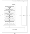
- the method for generating the dot-matrix code of the present disclosure includes:
- An information decoding subsystem is provided to parse a data stream generated by an encoding subsystem so as to obtain the original information, and the process includes: identifying a dot-matrix code with uniformly distributed information points from a printing medium using a mobile device; identifying encoded information of the dot-matrix code and decoding key thereof based on the image obtained (the image carrying the dot-matrix code); correcting obtained data using error correction coding; and when the error correction fails, which means that there are a relatively large number of errors and re-identification should be performed, returning to the first step (i.e., identifying the dot-matrix codes); when the error correction succeeds, parsing the data that has been error corrected; and obtaining the original information embedded in the image.
- Step S52 obtaining configuration information of the dot-matrix code image corresponding to the dot-matrix code.
- the configuration information of the dot-matrix code image includes a width and height, shading information, and a decryption key of the dot-matrix code image. Step S53, encrypting the information to be embedded to obtain encrypted information;
- Step S54 performing error correction coding on the encrypted information to obtain error-corrected information.
- the error correction coding of the encrypted information is performed using a concatenated code including Reed-Solomon (RS) codes and convolutional codes in combination with interleaving technology.
- RS Reed-Solomon
- Reed-Solomon coding is also called forward error correction coding, or channel coding, which was proposed by Irving S. Reed and Gustave Solomon in 1960 and has been widely used in the field of information storage and transmission.
- An RS coding system is divided into two parts: an encoder, which receives an original message and encodes it with additional parity check bit data, and a decoder, which processes encoded data and attempts to recover the original message.
- RS codes are a special class of non-binary BCH codes with high error correction capability.
- RS (n, k) as an example, k denotes the length of message symbols, and n denotes that n-k check symbols are added to the message symbols to form a coding sequence of total length n, i.e., the total codeword length.
- System coding is usually used to add check symbols, and system coding means adding check symbols directly after the original data information without altering the original information.
- Convolutional codes were first introduced by Elias et al. in 1955. Unlike block codes, which encode information in separate blocks, convolutional codes encode continuous input sequences into continuous output sequences. In block codes, the n-k check elements in each group are only related to the k information elements in that group, and are independent of the information in other groups. However, in convolutional codes, when its encoder codifies k information code elements into n code elements, these n code elements are not only related to the k information code elements of the current segment, but also related to the information of the previous (m-1) segments (m is the constraint length of the code).
- Convolutional codes can be described using the notation (n, k, m), where k is the number of bits input to the convolutional encoder at a time, n is the number of bits in the output n-tuple codeword corresponding to each k-tuple codeword, and m is the coding memory, which is the number of k-tuples in the convolutional encoder, also known as the constraint length.
- Convolutional codes encode k-tuple input codewords into n-tuple output codewords, but k and n are usually small, making them particularly suitable for transmission in serial form with low delay.
- the error correction performance of convolutional codes increases with m, while the error rate decreases exponentially with N.
- Viterbi decoding is an algorithm that finds the path on the code trellis with the minimum distance (or other measure) to the received sequence. It is similar to the shortest path algorithm used in operations research. Currently, the most widely used decoding algorithm is Viterbi decoding.
- Interleaving coding is a communication technology that mitigates mobile communication signal fading in practical mobile communication environments. Fading in a practical mobile communication environment will cause bursty errors in digital signal transmission. Interleaving coding can be used to discrete and correct such bursty errors and improve the transmission characteristics of mobile communication.
- the purpose of interleaving coding is to discrete a long bursty error into random errors, and then use the coding technique for correcting random errors to eliminate the random errors.
- the larger the depth of interleaving the greater the discretization, and the stronger the ability to resist bursty errors. However, the larger the depth of interleaving, the longer the processing time of interleaving coding, which increases the data transmission delay.
- Step S55 the error-corrected information (i.e., the information to be embedded that has been encrypted and then error-corrected) is converted into a dot-matrix code constructed based on the above-mentioned method for constructing a dot-matrix code.
- converting the error-corrected information into the dot-matrix code includes:
- Step S56 generating an image shading based on the configuration information of the dot-matrix code image.
- Step S57 embedding the dot-matrix code on the image shading.
- the method for generating a dot-matrix code further includes printing the dot-matrix code on a surface of a material; wherein the material includes one or more of paper, metal, ceramics, and plastic.
- one embodiment of the present disclosure provides a dot-matrix code generating terminal, which includes a processor 61, and a memory 62.
- the memory 62 is configured to store a computer program.
- the memory 62 includes one or more of a ROM, RAM, magnetic disk, U disk, memory card, optical disk, or other medium that can store program codes.
- the processor 61 is connected to the memory 62 for executing the computer program stored in the memory 62 to cause the terminal to perform the method for generating the dot-matrix code described above.
- the processor 61 may be a general processor, including a Central Processing Unit (CPU), a Network Processor (NP), and the like. It may also be a Digital Signal Processor (DSP), an Application Specific Integrated Circuit (ASIC), a Field-Programmable Gate Array (FPGA), a Graphic Processing Unit (GPU), or other programmable logic devices, discrete gate or transistor logic devices, or discrete hardware components.
- CPU Central Processing Unit
- NP Network Processor
- DSP Digital Signal Processor
- ASIC Application Specific Integrated Circuit
- FPGA Field-Programmable Gate Array
- GPU Graphic Processing Unit
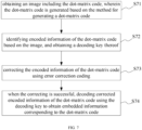
- one embodiment of the present disclosure provides a method for reading a dot-matrix code, which includes the following steps.
- Step S71 obtaining an image including the dot-matrix code, in which the dot-matrix code is generated based on the method for generating a dot-matrix code described above.
- Step S72 identifying encoded information of the dot-matrix code based on the image, and obtaining a decoding key thereof; Specifically, the decoding key is obtained from pre-obtained configuration information of the image.
- Step S73 correcting the encoded information of the dot-matrix code using error correction coding; and Specifically, performing error correction on the encoded information of the dot-matrix code, and if the error correction is successful, transmitting the corrected data to a decoding module; when the error correction fails, it means that there are a relatively large number of errors and re-identification of the dot-matrix code should be performed.
- the error correction efficiency of the method can be as high as 25% due to the use of concatenated codes combined with interleaving technology.
- the error tolerance rate of the dot-matrix code of the present disclosure is higher compared to conventional 2D codes with the same information capacity.
- Step S74 when the error correction is successful, decoding corrected encoded information of the dot-matrix code using the decoding key to obtain embedded information corresponding to the dot-matrix code.
- the error correction code decoding unit module is mainly?? As shown in FIG. 8 , one embodiment of the present disclosure provides a dot-matrix code reading terminal, which includes a processor 81, and a memory 82.
- the memory 82 is configured to store a computer program.
- the memory 82 includes one or more of a ROM, RAM, magnetic disk, U disk, memory card, optical disk, or other medium that can store program codes.
- the processor 81 is connected to the memory 82 for executing the computer program stored in the memory 82 to cause the terminal to perform the method for reading the dot-matrix code described above.
- the processor 81 may be a general processor, including a Central Processing Unit (CPU), a Network Processor (NP), and the like. It may also be a Digital Signal Processor (DSP), an Application Specific Integrated Circuit (ASIC), a Field-Programmable Gate Array (FPGA), or other programmable logic devices, discrete gate or transistor logic devices, or discrete hardware components. As shown in FIG.
- one embodiment of the present disclosure provides a dot-matrix code system, which includes the above-mentioned dot-matrix code generating terminal 91 and the above-mentioned dot-matrix code reading terminal 92, so as to realize the generation and reading of the dot-matrix code, as well as realizing the practical application of the dot-matrix code.
- the methods for constructing, generating, and reading a dot-matrix code, the dot-matrix code generation and reading terminals, and the dot-matrix code system of the present disclosure can provide uniformly distributed dot-matrix codes with information hiding features, satisfying practical need.
- the dot-matrix code of the present disclosure changes the way information is represented by 2D codes; specifically, it expands the range of information units and uses relative positions of information points in the information units to represent different information values stored in the information units. Within the same information unit, there is one and only one information point, and information points are relatively uniformly distributed within the dot-matrix code.
- the dot-matrix code of the present disclosure has no obvious position detection patterns or "markers", and its appearance is aesthetically pleasing without being obvious.
- the dot-matrix code of the present disclosure can be continuously replicated and cover a large surface, and arrangement and coloring of the 2D codes can serve as a basis of the appearance of the product, which is more conducive to hiding and beautifying the 2D codes.
- the dot-matrix code of the present disclosure can be printed on surfaces of different materials, such as paper, plastic, ceramics, metal, etc., without blocking the background patterns, which also makes the product more aesthetically pleasing.
- the uniqueness, integrity and availability of the dot-matrix code are guaranteed, which provides it the features of anti-tampering and anti-copying. Therefore, the present disclosure effectively overcomes various shortcomings in the existing technology and has high industrial utilization value.
Landscapes
- Physics & Mathematics (AREA)
- Engineering & Computer Science (AREA)
- General Physics & Mathematics (AREA)
- Theoretical Computer Science (AREA)
- Mathematical Physics (AREA)
- Algebra (AREA)
- Pure & Applied Mathematics (AREA)
- Probability & Statistics with Applications (AREA)
- Health & Medical Sciences (AREA)
- Electromagnetism (AREA)
- General Health & Medical Sciences (AREA)
- Toxicology (AREA)
- Artificial Intelligence (AREA)
- Computer Vision & Pattern Recognition (AREA)
- Editing Of Facsimile Originals (AREA)
- Management, Administration, Business Operations System, And Electronic Commerce (AREA)
Claims (15)
- Verfahren zur Erzeugung eines Punktmatrixcodes, umfassend:Erzeugen einer Vielzahl von Informationseinheiten, die in einer NxN-Matrix angeordnet sind, wobei N eine natürliche Zahl größer oder gleich 2 ist;Konfigurieren der Vielzahl von Informationseinheiten als Informationseinheitsmodule und/oder Markierungseinheitsmodule, wobei jede Informationseinheit einen und nur einen Informationspunkt enthält;Speichern, in jedem der Informationseinheitsmodule, eines Werts basierend auf einer relativen Position des Informationspunkts innerhalb des entsprechenden Informationseinheitsmoduls; undSignalisieren von Identifikationsinformationen des Punktmatrixcodes durch eine Anordnung einer Teilmenge der Informationspunkte, wobei die Teilmenge der Informationspunkte in den Markierungseinheitsmodulen enthalten ist; wobei von den Informationspunkten, die sich in den Markierungseinheitsmodulen befinden, diejenigen, die eine obere Grenze, eine untere Grenze oder Eckpunkte des Punktmatrixcodes darstellen, sich in Mitten der Markierungseinheitsmodule befinden, und diejenigen, die eine linke Grenze oder eine rechte Grenze darstellen, die keine Eckpunkte des Punktmatrixcodes enthalten, sich abwechselnd in linken oder rechten Abschnitten der Markierungseinheitsmodule befinden.
- Verfahren zur Erzeugung eines Punktmatrixcodes, umfassend:Erzeugen einer Vielzahl von Informationseinheiten, die in einer NxN-Matrix angeordnet sind, wobei N eine natürliche Zahl größer oder gleich 2 ist;Konfigurieren der Vielzahl von Informationseinheiten als Informationseinheitsmodule und/oder Markierungseinheitsmodule, wobei jede Informationseinheit einen und nur einen Informationspunkt enthält;Speichern, in jedem der Informationseinheitsmodule, eines Werts basierend auf einer relativen Position des Informationspunkts innerhalb des entsprechenden Informationseinheitsmoduls; undSignalisieren von Identifikationsinformationen des Punktmatrixcodes durch eine Anordnung einer Teilmenge der Informationspunkte, wobei die Teilmenge der Informationspunkte in den Markierungseinheitsmodulen enthalten ist; wobei von den Informationspunkten, die sich in den Markierungseinheitsmodulen befinden, diejenigen, die eine obere Grenze, eine untere Grenze, eine linke Grenze oder eine rechte Grenze des Punktmatrixcodes darstellen, sich in Mitten der Markierungseinheitsmodule befinden, und ein zentrales Markierungseinheitsmodul, das sich in der Mitte des gesamten Punktmatrixcodes befindet, einen Informationspunkt enthält, der sich im oberen linken Abschnitt des zentralen Markierungseinheitsmoduls befindet.
- Verfahren zur Erzeugung eines Punktmatrixcodes, umfassend:Erzeugen einer Vielzahl von Informationseinheiten, die in einer NxN-Matrix angeordnet sind, wobei N eine natürliche Zahl größer oder gleich 2 ist;Konfigurieren der Vielzahl von Informationseinheiten als Informationseinheitsmodule und/oder Markierungseinheitsmodule, wobei jede Informationseinheit einen und nur einen Informationspunkt enthält;Speichern, in jedem der Informationseinheitsmodule, eines Werts basierend auf einer relativen Position des Informationspunkts innerhalb des entsprechenden Informationseinheitsmoduls; undSignalisieren von Identifikationsinformationen des Punktmatrixcodes durch eine Anordnung einer Teilmenge der Informationspunkte, wobei die Teilmenge der Informationspunkte in den Markierungseinheitsmodulen enthalten ist; wobei von den Informationspunkten, die sich in den Markierungseinheitsmodulen befinden, diejenigen, die Grenzen des Punktmatrixcodes darstellen, die keine Eckpunkte enthalten, sich in Mitten der Markierungseinheitsmodule befinden, und diejenigen, die vier Eckpunkte des Punktmatrixcodes darstellen, sich in oberen linken Abschnitten der Markierungseinheitsmodule befinden.
- Verfahren zur Erzeugung des Punktmatrixcodes nach einem der Ansprüche 1-3, wobei die Identifikationsinformationen des Punktmatrixcodes eine Punktmatrixorientierung und Punktmatrixgrenzen umfassen.
- Verfahren zur Erzeugung des Punktmatrixcodes nach einem der Ansprüche 1-3, wobei von den Informationspunkten diejenigen, die sich in oberen linken, unteren linken, oberen rechten oder unteren rechten Abschnitten der Informationseinheitsmodule befinden, jeweils einen quaternären Wert darstellen.
- Verfahren zur Erzeugung des Punktmatrixcodes nach einem der Ansprüche 1-3, wobei Ecken des Punktmatrixcodes durch diejenigen der Informationspunkte angezeigt werden, die zusammen Bögen oder rechte Winkel bilden.
- Verfahren Erzeugen eines Punktmatrixcodes, umfassend:Erhalten von Informationen, die in den Punktmatrixcode einzubetten sind;Erhalten von Konfigurationsinformationen eines Punktmatrixcodebildes, das dem Punktmatrixcode entspricht;Verschlüsseln der Informationen, die einzubetten sind, um verschlüsselte Informationen zu erhalten;Durchführen einer Fehlerkorrekturcodierung an den verschlüsselten Informationen, um fehlerkorrigierte Informationen zu erhalten;Umwandeln der fehlerkorrigierten Informationen in einen Punktmatrixcode, der basierend auf einem Verfahren zum Erzeugen eines Punktmatrixcodes nach einem der Ansprüche 1-3 erzeugt wurde;Erzeugen einer Bildschattierung basierend auf den Konfigurationsinformationen des Punktmatrixcodebildes; undEinbetten des Punktmatrixcodes in die Bildschattierung.
- Verfahren zum Erzeugen des Punktmatrixcodes nach Anspruch 7, wobei die Fehlerkorrekturcodierung der verschlüsselten Informationen unter Verwenden eines verketteten Codes durchgeführt wird, der RS-Codes und Faltungscodes in Kombination mit Verschachtelungstechnologie umfasst.
- Verfahren zum Erzeugen des Punktmatrixcodes nach Anspruch 7, wobei das Umwandeln der fehlerkorrigierten Informationen in den Punktmatrixcode umfasst:Umwandeln einer hexadezimalen Zeichenfolge, die mit Fehlerkorrekturcodes codiert ist, in einen quaternären Datenstrom; undsequentielles Einbetten der Informationen, die einzubetten sind, in eine Punktmatrix von oben nach unten und von links nach rechts, um den Punktmatrixcode zu erzeugen.
- Verfahren zum Erzeugen des Punktmatrixcodes nach Anspruch 7, wobei die Konfigurationsinformationen des Punktmatrixcodebildes umfassen:
eine Breite und Höhe, Hintergrundinformationen und einen Entschlüsselungsschlüssel des Punktmatrixcodebildes. - Verfahren zum Erzeugen des Punktmatrixcodes nach Anspruch 7, ferner umfassend das Drucken des Punktmatrixcodes auf eine Oberfläche eines Materials; wobei das Material eines oder mehrere von Papier, Metall und Kunststoff umfasst.
- Punktmatrixcode erzeugendes Endgerät (91), umfassend einen Prozessor (61) und einen Speicher (62);wobei der Speicher (62) konfiguriert ist, um ein Computerprogramm zu speichern;wobei der Prozessor (61) zum Ausführen des in dem Speicher (62) gespeicherten Computerprogramms dient, um das Endgerät zu veranlassen, das Verfahren zum Erzeugen des Punktmatrixcodes nach Anspruch 7 durchzuführen.
- Verfahren zum Lesen eines durch das Verfahren nach Anspruch 7 erzeugten Punktmatrixcodes, umfassend:Erhalten eines Bildes, das den Punktmatrixcode umfasst;Identifizieren codierter Informationen des Punktmatrixcodes basierend auf dem Bild und Erhalten eines Dekodierungsschlüssels davon;Korrigieren der codierten Informationen des Punktmatrixcodes unter Verwenden einer Fehlerkorrekturcodierung; undwenn das Korrigieren erfolgreich ist, Dekodieren korrigierter codierter Informationen des Punktmatrixcodes unter Verwenden des Dekodierungsschlüssels, um eingebettete Informationen zu erhalten, die dem Punktmatrixcode entsprechen.
- Punktmatrixcode lesendes Endgerät (92), umfassend einen Prozessor (81) und einen Speicher (82);wobei der Speicher (82) konfiguriert ist, um ein Computerprogramm zu speichern;wobei der Prozessor (81) zum Ausführen des in dem Speicher (82) gespeicherten Computerprogramms verwendet wird, um das Endgerät zu veranlassen, das Verfahren zum Lesen des Punktmatrixcodes nach Anspruch 13 durchzuführen.
- Punktmatrixcodesystem, umfassend das Punktmatrixcode erzeugende Endgerät (91) nach Anspruch 12 und das Punktmatrixcode lesende Endgerät (92) nach Anspruch 14.
Applications Claiming Priority (2)
| Application Number | Priority Date | Filing Date | Title |
|---|---|---|---|
| CN202110077095.7A CN114861847B (zh) | 2021-01-20 | 2021-01-20 | 点阵码构建方法、生成读取方法及终端、点阵码系统 |
| PCT/CN2021/073774 WO2022155983A1 (zh) | 2021-01-20 | 2021-01-26 | 点阵码构建方法、生成读取方法及终端、点阵码系统 |
Publications (4)
| Publication Number | Publication Date |
|---|---|
| EP4273741A1 EP4273741A1 (de) | 2023-11-08 |
| EP4273741A4 EP4273741A4 (de) | 2024-06-19 |
| EP4273741C0 EP4273741C0 (de) | 2025-04-30 |
| EP4273741B1 true EP4273741B1 (de) | 2025-04-30 |
Family
ID=82549236
Family Applications (1)
| Application Number | Title | Priority Date | Filing Date |
|---|---|---|---|
| EP21920138.1A Active EP4273741B1 (de) | 2021-01-20 | 2021-01-26 | Verfahren zur konstruktion, zum erzeugen und zum lesen eines punktmatrixcodes, endgeräte zum erzeugen und lesen eines punktmatrixcodes und punktmatrixcodesystem |
Country Status (5)
| Country | Link |
|---|---|
| US (1) | US12223377B2 (de) |
| EP (1) | EP4273741B1 (de) |
| JP (1) | JP7681246B2 (de) |
| CN (1) | CN114861847B (de) |
| WO (1) | WO2022155983A1 (de) |
Families Citing this family (2)
| Publication number | Priority date | Publication date | Assignee | Title |
|---|---|---|---|---|
| CN115329919B (zh) * | 2022-10-08 | 2023-05-12 | 北京微点科学技术有限公司 | 基于微点码的随机附加点防伪方法和装置 |
| CN115470878B (zh) * | 2022-10-08 | 2023-05-02 | 北京微点科学技术有限公司 | 基于微点码的可变防伪超线防伪方法和装置 |
Family Cites Families (22)
| Publication number | Priority date | Publication date | Assignee | Title |
|---|---|---|---|---|
| JP3639328B2 (ja) * | 1994-10-14 | 2005-04-20 | オリンパス株式会社 | 情報記録媒体、2次元コード、情報再生システム、及び情報再生方法 |
| JP3676443B2 (ja) * | 1995-09-01 | 2005-07-27 | オリンパス株式会社 | 情報再生装置及び情報再生方法 |
| US6751352B1 (en) * | 2000-05-25 | 2004-06-15 | Hewlett-Packard Development Company, L.P. | Method and apparatus for generating and decoding a visually significant barcode |
| US7175095B2 (en) * | 2001-09-13 | 2007-02-13 | Anoto Ab | Coding pattern |
| WO2003107265A1 (en) * | 2002-06-18 | 2003-12-24 | Anoto Ab | Position-coding pattern |
| JP2004193727A (ja) * | 2002-12-09 | 2004-07-08 | Hitachi Ltd | 信号処理方法及び信号処理回路 |
| SE0203853D0 (sv) * | 2002-12-23 | 2002-12-23 | Anoto Ab | Informationskod |
| EP2511853A3 (de) * | 2005-04-28 | 2013-09-11 | YOSHIDA, Kenji | Punktmuster |
| WO2006135328A1 (en) * | 2005-06-17 | 2006-12-21 | Anoto Ab | Method and system for combining a position and information code |
| WO2007145317A1 (ja) * | 2006-06-16 | 2007-12-21 | Pioneer Corporation | 2次元コードパターン、2次元コードパターンの表示装置及びその読取装置 |
| TWI391862B (zh) * | 2008-06-06 | 2013-04-01 | Elan Microelectronics Corp | A two-dimensional dot code, a decoding apparatus, and a method thereof |
| US8004426B2 (en) * | 2008-10-14 | 2011-08-23 | Verizon Patent And Licensing Inc. | Systems and methods for recording parking space information |
| CN103390183B (zh) * | 2012-05-09 | 2019-07-19 | 顾泽苍 | 一种适用于手机识别的防伪代码的生成方法 |
| JP2018517199A (ja) * | 2015-03-30 | 2018-06-28 | テンプタイム コーポレーション | 動的環境データシステムを有する2次元バーコード、方法および装置 |
| JP3200549U (ja) * | 2015-08-07 | 2015-10-22 | 株式会社アポロジャパン | 埋め込み印刷コード |
| CN105760919B (zh) * | 2016-02-06 | 2018-08-07 | 深圳市天朗时代科技有限公司 | 一种点阵二维码的编码和识别方法 |
| CN105894067B (zh) * | 2016-02-06 | 2018-08-07 | 深圳市天朗时代科技有限公司 | 一种点阵二维码的编码和识读方法 |
| JP2017191420A (ja) * | 2016-04-13 | 2017-10-19 | 溝口 さとし | 二次元コード記録媒体および二次元コード読取方法 |
| CN106874819B (zh) * | 2016-11-22 | 2019-03-26 | 复旦大学 | 可由手机识别的稀疏点阵码控制方法 |
| US11062108B2 (en) * | 2017-11-07 | 2021-07-13 | Digimarc Corporation | Generating and reading optical codes with variable density to adapt for visual quality and reliability |
| CN110689100B (zh) * | 2019-09-25 | 2021-01-26 | 诚联网科技发展有限公司 | 基于突出中央图案的数据点阵编解码方法、系统及介质 |
| CN111832680B (zh) * | 2020-07-16 | 2024-07-09 | 网易有道信息技术(北京)有限公司 | 点阵码的编码方法、识读方法、编码装置和识读装置 |
-
2021
- 2021-01-20 CN CN202110077095.7A patent/CN114861847B/zh active Active
- 2021-01-26 JP JP2023567084A patent/JP7681246B2/ja active Active
- 2021-01-26 US US18/273,040 patent/US12223377B2/en active Active
- 2021-01-26 EP EP21920138.1A patent/EP4273741B1/de active Active
- 2021-01-26 WO PCT/CN2021/073774 patent/WO2022155983A1/zh not_active Ceased
Also Published As
| Publication number | Publication date |
|---|---|
| EP4273741C0 (de) | 2025-04-30 |
| US12223377B2 (en) | 2025-02-11 |
| CN114861847B (zh) | 2023-04-14 |
| US20240086670A1 (en) | 2024-03-14 |
| JP7681246B2 (ja) | 2025-05-22 |
| EP4273741A4 (de) | 2024-06-19 |
| JP2024505116A (ja) | 2024-02-02 |
| CN114861847A (zh) | 2022-08-05 |
| EP4273741A1 (de) | 2023-11-08 |
| WO2022155983A1 (zh) | 2022-07-28 |
Similar Documents
| Publication | Publication Date | Title |
|---|---|---|
| KR100414524B1 (ko) | 복호 특성이 우수하며 단계별 에러레벨조정이 가능한2차원 코드 및 그 코드의 인코딩 디코딩 방법 | |
| CN103400174B (zh) | 一种二维码的编码方法、解码方法及系统 | |
| US6321986B1 (en) | Robust machine-readable symbology and method and apparatus for printing and reading same | |
| Shi et al. | Interleaving for combating bursts of errors | |
| CN106815544B (zh) | 一种基于二维码的信息隐藏方法 | |
| JP3742389B2 (ja) | 巡回位置符号 | |
| US6149059A (en) | Bar code symbology capable of encoding bytes, words, 16-bit characters, etc. and method and apparatus for printing and reading same | |
| CN105447546A (zh) | 可嵌入大比例图形的二维码及其编码和解码方法和设备 | |
| CN107545289A (zh) | 矩阵式二维码的编码方法及解码方法 | |
| EP4273741B1 (de) | Verfahren zur konstruktion, zum erzeugen und zum lesen eines punktmatrixcodes, endgeräte zum erzeugen und lesen eines punktmatrixcodes und punktmatrixcodesystem | |
| CN107392270B (zh) | 一种二维码生成方法 | |
| US8360333B2 (en) | HD barcode | |
| KR101119310B1 (ko) | 데이터의 코딩 및 디코딩 | |
| CN106874819A (zh) | 可由手机识别的稀疏点阵码控制方法 | |
| CN108734048A (zh) | 基于专有码的多维度二维码生成与译码方法 | |
| CN107443922B (zh) | 一种防伪二维码生成系统 | |
| US8544741B2 (en) | Data block offset encoding method for coordinates | |
| US7611067B2 (en) | Printed material with identification function, image generating apparatus, image processing apparatus, image generating method, image processing method, and program product therefor | |
| EP3265998B1 (de) | Multidimensionale zyklische symbole | |
| CN112418374B (zh) | 一种信息码生成方法 | |
| EP3924881B1 (de) | Hybrider zweidimensionaler strichcodeleser | |
| Pei et al. | Codec system design for continuous color barcode symbols | |
| Hole et al. | Encryption and decryption of data using QR authentication system | |
| CN113557530A (zh) | 混合二维条形码和混合二维条形码生成器 | |
| CN118821825A (zh) | 一种基于Android平台的彩色QR呈现方法 |
Legal Events
| Date | Code | Title | Description |
|---|---|---|---|
| STAA | Information on the status of an ep patent application or granted ep patent |
Free format text: STATUS: THE INTERNATIONAL PUBLICATION HAS BEEN MADE |
|
| PUAI | Public reference made under article 153(3) epc to a published international application that has entered the european phase |
Free format text: ORIGINAL CODE: 0009012 |
|
| STAA | Information on the status of an ep patent application or granted ep patent |
Free format text: STATUS: REQUEST FOR EXAMINATION WAS MADE |
|
| 17P | Request for examination filed |
Effective date: 20230731 |
|
| AK | Designated contracting states |
Kind code of ref document: A1 Designated state(s): AL AT BE BG CH CY CZ DE DK EE ES FI FR GB GR HR HU IE IS IT LI LT LU LV MC MK MT NL NO PL PT RO RS SE SI SK SM TR |
|
| DAV | Request for validation of the european patent (deleted) | ||
| DAX | Request for extension of the european patent (deleted) | ||
| A4 | Supplementary search report drawn up and despatched |
Effective date: 20240523 |
|
| RIC1 | Information provided on ipc code assigned before grant |
Ipc: G06K 19/06 20060101ALI20240516BHEP Ipc: G06K 7/14 20060101AFI20240516BHEP |
|
| GRAP | Despatch of communication of intention to grant a patent |
Free format text: ORIGINAL CODE: EPIDOSNIGR1 |
|
| STAA | Information on the status of an ep patent application or granted ep patent |
Free format text: STATUS: GRANT OF PATENT IS INTENDED |
|
| INTG | Intention to grant announced |
Effective date: 20250206 |
|
| GRAS | Grant fee paid |
Free format text: ORIGINAL CODE: EPIDOSNIGR3 |
|
| GRAA | (expected) grant |
Free format text: ORIGINAL CODE: 0009210 |
|
| STAA | Information on the status of an ep patent application or granted ep patent |
Free format text: STATUS: THE PATENT HAS BEEN GRANTED |
|
| AK | Designated contracting states |
Kind code of ref document: B1 Designated state(s): AL AT BE BG CH CY CZ DE DK EE ES FI FR GB GR HR HU IE IS IT LI LT LU LV MC MK MT NL NO PL PT RO RS SE SI SK SM TR |
|
| REG | Reference to a national code |
Ref country code: CH Ref legal event code: EP Ref country code: GB Ref legal event code: FG4D |
|
| REG | Reference to a national code |
Ref country code: IE Ref legal event code: FG4D |
|
| REG | Reference to a national code |
Ref country code: DE Ref legal event code: R096 Ref document number: 602021030186 Country of ref document: DE |
|
| U01 | Request for unitary effect filed |
Effective date: 20250516 |
|
| U07 | Unitary effect registered |
Designated state(s): AT BE BG DE DK EE FI FR IT LT LU LV MT NL PT RO SE SI Effective date: 20250522 |
|
| PG25 | Lapsed in a contracting state [announced via postgrant information from national office to epo] |
Ref country code: ES Free format text: LAPSE BECAUSE OF FAILURE TO SUBMIT A TRANSLATION OF THE DESCRIPTION OR TO PAY THE FEE WITHIN THE PRESCRIBED TIME-LIMIT Effective date: 20250430 |
|
| PG25 | Lapsed in a contracting state [announced via postgrant information from national office to epo] |
Ref country code: GR Free format text: LAPSE BECAUSE OF FAILURE TO SUBMIT A TRANSLATION OF THE DESCRIPTION OR TO PAY THE FEE WITHIN THE PRESCRIBED TIME-LIMIT Effective date: 20250731 Ref country code: NO Free format text: LAPSE BECAUSE OF FAILURE TO SUBMIT A TRANSLATION OF THE DESCRIPTION OR TO PAY THE FEE WITHIN THE PRESCRIBED TIME-LIMIT Effective date: 20250730 |
|
| PG25 | Lapsed in a contracting state [announced via postgrant information from national office to epo] |
Ref country code: PL Free format text: LAPSE BECAUSE OF FAILURE TO SUBMIT A TRANSLATION OF THE DESCRIPTION OR TO PAY THE FEE WITHIN THE PRESCRIBED TIME-LIMIT Effective date: 20250430 |
|
| PG25 | Lapsed in a contracting state [announced via postgrant information from national office to epo] |
Ref country code: HR Free format text: LAPSE BECAUSE OF FAILURE TO SUBMIT A TRANSLATION OF THE DESCRIPTION OR TO PAY THE FEE WITHIN THE PRESCRIBED TIME-LIMIT Effective date: 20250430 |
|
| PG25 | Lapsed in a contracting state [announced via postgrant information from national office to epo] |
Ref country code: RS Free format text: LAPSE BECAUSE OF FAILURE TO SUBMIT A TRANSLATION OF THE DESCRIPTION OR TO PAY THE FEE WITHIN THE PRESCRIBED TIME-LIMIT Effective date: 20250731 |
|
| PG25 | Lapsed in a contracting state [announced via postgrant information from national office to epo] |
Ref country code: IS Free format text: LAPSE BECAUSE OF FAILURE TO SUBMIT A TRANSLATION OF THE DESCRIPTION OR TO PAY THE FEE WITHIN THE PRESCRIBED TIME-LIMIT Effective date: 20250830 |
|
| PG25 | Lapsed in a contracting state [announced via postgrant information from national office to epo] |
Ref country code: SM Free format text: LAPSE BECAUSE OF FAILURE TO SUBMIT A TRANSLATION OF THE DESCRIPTION OR TO PAY THE FEE WITHIN THE PRESCRIBED TIME-LIMIT Effective date: 20250430 |
|
| PG25 | Lapsed in a contracting state [announced via postgrant information from national office to epo] |
Ref country code: CZ Free format text: LAPSE BECAUSE OF FAILURE TO SUBMIT A TRANSLATION OF THE DESCRIPTION OR TO PAY THE FEE WITHIN THE PRESCRIBED TIME-LIMIT Effective date: 20250430 |
|
| PG25 | Lapsed in a contracting state [announced via postgrant information from national office to epo] |
Ref country code: SK Free format text: LAPSE BECAUSE OF FAILURE TO SUBMIT A TRANSLATION OF THE DESCRIPTION OR TO PAY THE FEE WITHIN THE PRESCRIBED TIME-LIMIT Effective date: 20250430 |
|
| REG | Reference to a national code |
Ref country code: CH Ref legal event code: U11 Free format text: ST27 STATUS EVENT CODE: U-0-0-U10-U11 (AS PROVIDED BY THE NATIONAL OFFICE) Effective date: 20260201 |
|
| U20 | Renewal fee for the european patent with unitary effect paid |
Year of fee payment: 6 Effective date: 20260113 |
|
| PLBE | No opposition filed within time limit |
Free format text: ORIGINAL CODE: 0009261 |
|
| STAA | Information on the status of an ep patent application or granted ep patent |
Free format text: STATUS: NO OPPOSITION FILED WITHIN TIME LIMIT |
|
| REG | Reference to a national code |
Ref country code: CH Ref legal event code: L10 Free format text: ST27 STATUS EVENT CODE: U-0-0-L10-L00 (AS PROVIDED BY THE NATIONAL OFFICE) Effective date: 20260311 |
|
| 26N | No opposition filed |
Effective date: 20260202 |
|
| PGFP | Annual fee paid to national office [announced via postgrant information from national office to epo] |
Ref country code: GB Payment date: 20260120 Year of fee payment: 6 |