EP4273631A2 - Developer supply container and developer supply system - Google Patents
Developer supply container and developer supply system Download PDFInfo
- Publication number
- EP4273631A2 EP4273631A2 EP23192115.6A EP23192115A EP4273631A2 EP 4273631 A2 EP4273631 A2 EP 4273631A2 EP 23192115 A EP23192115 A EP 23192115A EP 4273631 A2 EP4273631 A2 EP 4273631A2
- Authority
- EP
- European Patent Office
- Prior art keywords
- developer
- supply container
- developer supply
- rotatable
- discharge opening
- Prior art date
- Legal status (The legal status is an assumption and is not a legal conclusion. Google has not performed a legal analysis and makes no representation as to the accuracy of the status listed.)
- Pending
Links
- 238000007599 discharging Methods 0.000 claims abstract description 31
- 238000004891 communication Methods 0.000 claims abstract description 9
- 239000012530 fluid Substances 0.000 claims abstract description 8
- 239000000463 material Substances 0.000 description 21
- 238000007789 sealing Methods 0.000 description 9
- 238000003780 insertion Methods 0.000 description 8
- 230000037431 insertion Effects 0.000 description 8
- 238000011144 upstream manufacturing Methods 0.000 description 7
- 230000008859 change Effects 0.000 description 4
- 230000008602 contraction Effects 0.000 description 4
- 230000006870 function Effects 0.000 description 4
- 238000000034 method Methods 0.000 description 3
- 239000000843 powder Substances 0.000 description 3
- 230000001105 regulatory effect Effects 0.000 description 3
- 238000003756 stirring Methods 0.000 description 3
- XECAHXYUAAWDEL-UHFFFAOYSA-N acrylonitrile butadiene styrene Chemical compound C=CC=C.C=CC#N.C=CC1=CC=CC=C1 XECAHXYUAAWDEL-UHFFFAOYSA-N 0.000 description 2
- 229920000122 acrylonitrile butadiene styrene Polymers 0.000 description 2
- 239000004676 acrylonitrile butadiene styrene Substances 0.000 description 2
- 238000006073 displacement reaction Methods 0.000 description 2
- 238000012423 maintenance Methods 0.000 description 2
- -1 polypropylene Polymers 0.000 description 2
- 230000008569 process Effects 0.000 description 2
- 238000000926 separation method Methods 0.000 description 2
- 238000012546 transfer Methods 0.000 description 2
- 239000004698 Polyethylene Substances 0.000 description 1
- 239000004743 Polypropylene Substances 0.000 description 1
- 239000004793 Polystyrene Substances 0.000 description 1
- 230000009471 action Effects 0.000 description 1
- 230000001154 acute effect Effects 0.000 description 1
- 230000008901 benefit Effects 0.000 description 1
- 230000015572 biosynthetic process Effects 0.000 description 1
- 230000006835 compression Effects 0.000 description 1
- 238000007906 compression Methods 0.000 description 1
- 238000011109 contamination Methods 0.000 description 1
- 230000001276 controlling effect Effects 0.000 description 1
- 230000000694 effects Effects 0.000 description 1
- 230000005489 elastic deformation Effects 0.000 description 1
- 239000013013 elastic material Substances 0.000 description 1
- 239000006260 foam Substances 0.000 description 1
- 239000011521 glass Substances 0.000 description 1
- 230000007246 mechanism Effects 0.000 description 1
- 239000000203 mixture Substances 0.000 description 1
- 239000002245 particle Substances 0.000 description 1
- 230000000149 penetrating effect Effects 0.000 description 1
- 229920000728 polyester Polymers 0.000 description 1
- 229920000573 polyethylene Polymers 0.000 description 1
- 229920001155 polypropylene Polymers 0.000 description 1
- 229920002223 polystyrene Polymers 0.000 description 1
- 238000012545 processing Methods 0.000 description 1
- 239000011347 resin Substances 0.000 description 1
- 229920005989 resin Polymers 0.000 description 1
Images


Classifications
-
- G—PHYSICS
- G03—PHOTOGRAPHY; CINEMATOGRAPHY; ANALOGOUS TECHNIQUES USING WAVES OTHER THAN OPTICAL WAVES; ELECTROGRAPHY; HOLOGRAPHY
- G03G—ELECTROGRAPHY; ELECTROPHOTOGRAPHY; MAGNETOGRAPHY
- G03G21/00—Arrangements not provided for by groups G03G13/00 - G03G19/00, e.g. cleaning, elimination of residual charge
- G03G21/16—Mechanical means for facilitating the maintenance of the apparatus, e.g. modular arrangements
- G03G21/1642—Mechanical means for facilitating the maintenance of the apparatus, e.g. modular arrangements for connecting the different parts of the apparatus
- G03G21/1647—Mechanical connection means
-
- G—PHYSICS
- G03—PHOTOGRAPHY; CINEMATOGRAPHY; ANALOGOUS TECHNIQUES USING WAVES OTHER THAN OPTICAL WAVES; ELECTROGRAPHY; HOLOGRAPHY
- G03G—ELECTROGRAPHY; ELECTROPHOTOGRAPHY; MAGNETOGRAPHY
- G03G15/00—Apparatus for electrographic processes using a charge pattern
- G03G15/06—Apparatus for electrographic processes using a charge pattern for developing
- G03G15/08—Apparatus for electrographic processes using a charge pattern for developing using a solid developer, e.g. powder developer
- G03G15/0822—Arrangements for preparing, mixing, supplying or dispensing developer
- G03G15/0865—Arrangements for supplying new developer
- G03G15/0867—Arrangements for supplying new developer cylindrical developer cartridges, e.g. toner bottles for the developer replenishing opening
- G03G15/087—Developer cartridges having a longitudinal rotational axis, around which at least one part is rotated when mounting or using the cartridge
- G03G15/0872—Developer cartridges having a longitudinal rotational axis, around which at least one part is rotated when mounting or using the cartridge the developer cartridges being generally horizontally mounted parallel to its longitudinal rotational axis
-
- G—PHYSICS
- G03—PHOTOGRAPHY; CINEMATOGRAPHY; ANALOGOUS TECHNIQUES USING WAVES OTHER THAN OPTICAL WAVES; ELECTROGRAPHY; HOLOGRAPHY
- G03G—ELECTROGRAPHY; ELECTROPHOTOGRAPHY; MAGNETOGRAPHY
- G03G15/00—Apparatus for electrographic processes using a charge pattern
- G03G15/06—Apparatus for electrographic processes using a charge pattern for developing
- G03G15/08—Apparatus for electrographic processes using a charge pattern for developing using a solid developer, e.g. powder developer
- G03G15/0822—Arrangements for preparing, mixing, supplying or dispensing developer
- G03G15/0877—Arrangements for metering and dispensing developer from a developer cartridge into the development unit
- G03G15/0881—Sealing of developer cartridges
- G03G15/0886—Sealing of developer cartridges by mechanical means, e.g. shutter, plug
-
- G—PHYSICS
- G03—PHOTOGRAPHY; CINEMATOGRAPHY; ANALOGOUS TECHNIQUES USING WAVES OTHER THAN OPTICAL WAVES; ELECTROGRAPHY; HOLOGRAPHY
- G03G—ELECTROGRAPHY; ELECTROPHOTOGRAPHY; MAGNETOGRAPHY
- G03G21/00—Arrangements not provided for by groups G03G13/00 - G03G19/00, e.g. cleaning, elimination of residual charge
- G03G21/16—Mechanical means for facilitating the maintenance of the apparatus, e.g. modular arrangements
- G03G21/1661—Mechanical means for facilitating the maintenance of the apparatus, e.g. modular arrangements means for handling parts of the apparatus in the apparatus
- G03G21/1676—Mechanical means for facilitating the maintenance of the apparatus, e.g. modular arrangements means for handling parts of the apparatus in the apparatus for the developer unit
-
- G—PHYSICS
- G03—PHOTOGRAPHY; CINEMATOGRAPHY; ANALOGOUS TECHNIQUES USING WAVES OTHER THAN OPTICAL WAVES; ELECTROGRAPHY; HOLOGRAPHY
- G03G—ELECTROGRAPHY; ELECTROPHOTOGRAPHY; MAGNETOGRAPHY
- G03G15/00—Apparatus for electrographic processes using a charge pattern
- G03G15/06—Apparatus for electrographic processes using a charge pattern for developing
- G03G15/08—Apparatus for electrographic processes using a charge pattern for developing using a solid developer, e.g. powder developer
- G03G15/0822—Arrangements for preparing, mixing, supplying or dispensing developer
- G03G15/0865—Arrangements for supplying new developer
- G03G15/0867—Arrangements for supplying new developer cylindrical developer cartridges, e.g. toner bottles for the developer replenishing opening
-
- G—PHYSICS
- G03—PHOTOGRAPHY; CINEMATOGRAPHY; ANALOGOUS TECHNIQUES USING WAVES OTHER THAN OPTICAL WAVES; ELECTROGRAPHY; HOLOGRAPHY
- G03G—ELECTROGRAPHY; ELECTROPHOTOGRAPHY; MAGNETOGRAPHY
- G03G2215/00—Apparatus for electrophotographic processes
- G03G2215/06—Developing structures, details
- G03G2215/066—Toner cartridge or other attachable and detachable container for supplying developer material to replace the used material
- G03G2215/0663—Toner cartridge or other attachable and detachable container for supplying developer material to replace the used material having a longitudinal rotational axis, around which at least one part is rotated when mounting or using the cartridge
- G03G2215/0665—Generally horizontally mounting of said toner cartridge parallel to its longitudinal rotational axis
- G03G2215/0668—Toner discharging opening at one axial end
Definitions
- the present invention relates to a developer supply container dismountably mountable to a developer receiving apparatus and a developer supplying system.
- the developer supply container is mountable to and dismountable from a developer receiving apparatus provided in the image forming apparatus, and the developer receiving portion of the developer receiving apparatus is displaced toward the discharge opening of the developer supply container in accordance with the mounting operation of the developer supply container ( JP2013 - 015826A ).
- An object of the present invention is to provide a developer supply container and a developer supplying system capable of improving easiness of operation by reducing the operation force when mounting the developer supply container.
- a developer supply container detachably mountable to a developer receiving apparatus, the developer receiving apparatus including a receiving opening for receiving a developer, and a portion-to-be-engaged integrally displaceable with the developer receiving portion, said developer supply container comprising a rotatable developer accommodating portion accommodating the developer; a gear for transmitting a driving force to said developer accommodating portion; a developer discharging portion rotatable relative to said developer accommodating portion and provided at a bottom side with a discharge opening for discharging the developer from said developer accommodating portion; a rotatable engaging portion engageable with the portion-to-be-engaged with a mounting operation of said developer supply container to displace the developer receiving portion so as to move the receiving opening toward said discharge opening, thus bring the receiving opening in fluid communication with said discharge opening; a shaft portion which is provided between one end portion of said engaging portion and other end portion thereof with respect to a rotational axis direction of said developer accommodating portion and which rotatably supports said engageable member; and
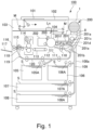
- the image forming apparatus 100 includes an original reading device 103 at a top of a main assembly 100a of the image forming apparatus.
- An original 101 is placed on an original platen glass 102.
- a light image corresponding to image information of the original 101 is imaged, using a plurality of mirrors M and the lens Ln of the original reading device 103, on a photosensitive drum 104 which is a cylindrical photosensitive member as an image bearing member to form an electrostatic latent image.
- This electrostatic latent image is visualized using toner (one component magnetic toner) as a developer (dry powder) by a dry type developing device (one-component developing device) 201.
- a one-component magnetic toner is used as the developer to be supplied from the developer supply container 1 (also referred to as a toner cartridge), but the present invention is not limited to such an example, and it may be of a structure as will be described hereinafter.
- one component nonmagnetic toner is supplied as a developer.
- non-magnetic toner is supplied as the developer when using a two-component developer which develops the image using a two component developer prepared by mixing magnetic carrier and nonmagnetic toner.
- the developer a structure may be employed in which the magnetic carrier is also supplied together with the non-magnetic toner.
- a developing device 201 shown in Figure 1 develops the electrostatic latent image formed on the photosensitive drum 104 using the toner as the developer based on the image information of the original 101.
- a developer supplying system 200 is connected to developing device 201, and the developer supplying system 200 includes a developer supply container 1 and a developer receiving apparatus 8 relative to which the developer supply container 1 is mountable and dismountable. Developer supplying system 200 will be described hereinafter.
- the developing device 201 includes a developer hopper portion 201a and a developing roller 201f.
- a stirring member 201c for stirring the developer supplied from the developer supply container 1 is provided.
- the developer stirred by the stirring member 201c is fed to a feeding member (201e) side by a feeding member 201d.
- the developer which has been sequentially fed by the feeding members 201e and 201b is carried on the developing roller 201f and finally supplied to a developing zone formed with the photosensitive drum 104.
- a single component developer is used, and therefore, the toner as the developer is supplied from the developer supply container 1 to the developing device 201.
- Cassettes 105 to 108 contain recording materials S such as sheets of paper.
- recording materials S such as sheets of paper.
- a cassette containing an optimum recording material S among the sheets contained in these cassettes 105 to 108 is selected on the basis of the information inputted by the operator (user) on the operation portion 100d ( Figure 2 ) of the image forming apparatus 100 or on the basis of the size of the original 101.
- the recording material S it is not limited to sheets of paper, but it may be an OHP sheet or the like as the case may be.
- One sheet of recording material S fed by the feeding and separating devices 105A to 108A is fed to registration rollers 110 by way of a feeding portion 109. Then, the recording material S is fed in synchronization with the rotation of the photosensitive drum 104 and the scan timing of the original reading device 103.
- a transfer charging device 111 and a separation charging device 112 are provided at positions opposing the photosensitive drum 104 on a downstream side of the registration roller 110 in the recording material feeding direction.
- the image of the developer (toner image) formed on the photosensitive drum 104 is transferred onto the recording material S fed by the registration roller 110, by a transfer charging device 111.
- the recording material S onto which the toner image is transferred is separated from the photosensitive drum 104 by a separation charging device 112.
- heat and pressure are applied to the recording material S fed by the feeding portion 113 in a fixing portion 114, so that the toner image is fixed on the recording material.
- the recording material S to which the toner image is fixed passes through a discharge/reversing portion 115 and is discharged to the discharge tray 117 by the discharge roller 116, in case of single-sided copy.
- the recording material S passes through the discharge/reversing portion 115, and the recording material S is partly discharged to the outside of the apparatus once by the discharge roller 116.
- the position of the switching member 118 is switched, and the discharge roller 116 is rotated counterclockwise, by which the recording material S is fed again into the apparatus.
- the recording material S is fed to the registration roller 110 by way of the re-feeding and feeding portions 119 and 120, and is discharged to the discharge tray 117 by way of the same path as in the case of single-sided copying.
- image forming process devices such as a developing device 201, a cleaner portion 202, a primary charging device 203 and the like are provided around the photosensitive drum 104.
- the developing device 201 supplies the developer to the electrostatic latent image formed on the photosensitive drum 104 on the basis of the image information of the original 101 read by the original reading device 103 so as to develop the electrostatic latent image.
- the primary charging device 203 uniformly charges the surface of the photosensitive drum to form a desired electrostatic latent image on the photosensitive drum 104.
- the cleaner portion 202 has a function of removing the developer remaining on the photosensitive drum 104.
- the replacement cover 40 is a cover exclusively for mounting/dismounting (exchanging) the developer supply container 1, and is opened and closed only for dismounting/mounting the developer supply container 1.
- the maintenance operation for the image forming apparatus 100 is performed by opening/closing a front cover 100c.
- the replacement cover 40 and the front cover 100c may be integrated. In such a case, the replacement of the developer supply container 1 and the maintenance of the image forming apparatus 100 are performed by opening and closing the integrated cover (not shown).
- the developer receiving apparatus 8 constituting the developer supplying system 200 will be described.
- the developer receiving apparatus 8 is provided with a mounting portion (mounting space) 8f to which the developer supply container 1 is dismountably mounted.
- the mounting portion 8f is provided with an insertion guide 8e for guiding the developer supply container 1 in the mounting and dismounting directions.
- the structure is such that the dismounting direction B of the developer supply container 1 is opposite to the direction A of mounting the developer supply container 1 by the insertion guide 8e.
- the developer receiving apparatus 8 has a driving gear 9 which functions as a driving mechanism for driving the developer supply container 1.
- a rotational driving force is transmitted to the gear 9 from a driving motor 500 by way of a driving gear train (not shown), so that the gear 9 applies the rotational driving force to the developer supply container 1 mounted in the mounting portion 8 f.
- the operation of the driving motor 500 is controlled by the control device 600.
- the control device 600 controls overall of the image forming apparatus 100.
- the control device 600 has a CPU (Central Processing Unit), a ROM (Read Only Memory), and a RAM (Random Access Memory).
- the CPU controls each portion while reading the program corresponding to a control procedure stored in the ROM.
- working data and an input data are stored in the RAM, and the CPU executes control while looking up the data stored in the RAM on the basis of the program etc.
- a developer receiving portion 11 for receiving the developer discharged out of the developer supply container 1.
- the developer receiving portion 11 is connected to a container discharge opening 3a4 (part (a) of Figure 16 ) of the developer supply container 1 when the developer supply container 1 is mounted, and has a receiving opening 11a for receiving the developer discharged through the container discharge opening 3a4.
- the developer receiving portion 11 is mounted so as to be movable (displaceable) in the direction in which the receiving opening 11a moves toward and away from the container discharge opening 3a4 (in this embodiment, the direction crossing with the direction A in which the developer supply container 1 is mounted (more specifically, vertical direction relative to the developer receiving apparatus 8)).
- the developer receiving portion 11 is urged by an urging member 12, including a helical compression coil spring, for example, in such a direction that the receiving opening 11a moves away from the container discharge opening 3a4 (vertically downward, reverse direction to a direction of displacement). Therefore, the developer receiving portion 11 moves against the urging force of the urging member 12 when the receiving opening 11a moves toward the container discharge opening 3a4 (upward in the vertical direction).
- the direction in which the developer receiving portion 11 displaces in accordance with the mounting operation of the developer supply container 1 is an upward direction in the vertical direction. This direction is called upward (displacing direction, upward in the vertical direction) U, and the downward vertical direction in the opposite direction is called the downward direction D.
- a first shutter stopper portion 8a and a second shutter stopper portion 8b are provided on the upstream side of the developer receiving portion 11 in the mounting direction A.
- the first and second shutter stopper portions 8a and 8b regulate the relative movement of the shutter 4 (part (b) of Figure 5 ) which will be described hereinafter relative to the developer receiving apparatus 8.
- the shutter 4 moves relative to a part of the developer supply container 1 other than the shutter 4, such as the container body 2 described hereinafter.
- a sub-hopper 8c for temporarily storing the developer supplied from the developer supply container 1.
- a feeding screw 14 for feeding the developer to the developer hopper portion 201a ( Figure 1 ) which is a portion of the developing device 201, and an opening 8d communicating with the developer hopper portion 201a.
- the developer receiving portion 11 is provided with a main assembly seal 13 formed so as to surround the receiving opening 11a.
- the main assembly seal 13 is made of elastic material, foam or the like.
- the main assembly seal 13 in the state that the developer supply container 1 is mounted, the main assembly seal 13 is in close contact with an opening seal 3a5 surrounding the container discharge opening 3a4 of the developer supply container 1, with the shutter 4 described hereinafter sandwiched therebetween.
- the shutter opening (discharge port) 4j of the shutter 4 does not leak out of the receiving opening 11a which is a part of the developer feeding passage. That is, the main assembly seal 13 is provided around the receiving opening 11a, and when the communication between the receiving opening 11a and the shutter opening 4j is established, the sealing is performed by elastic deformation between the receiving opening 11a and the shutter opening 4j.
- a diameter of the receiving opening 11a is substantially the same as or slightly larger than a diameter of the shutter opening 4j of the shutter 4, in order to prevent the interior of the mounting portion 8f from being contaminated by the developer. This is because if the diameter of the receiving opening 11a is smaller than the diameter of the shutter opening 4j, the developer discharged from the shutter opening 4j is more likely to be deposited on the upper surface of the main assembly seal 13. If the developer is deposited on the lower surface of the developer supply container 1 at the time of mounting/dismounting operation of the developer supply container 1, it becomes a cause of contamination by the developer.
- the diameter of the receiving opening 11a is roughly the same as or about 2 mm larger than the diameter of the shutter opening 4j.
- the diameter of the shutter opening 4j of the shutter 4 is a fine hole (pinhole) of about 2 mm in diameter
- the diameter of the receiving opening 11a is about 3 mm.
- an engaged portion (portion to be engaged) 11b projecting toward the center side is provided on the side surface of the developer receiving portion 11.
- the engaged portion 11b is directly engaged with the engaging portion 30 (part (a) in Figure 7 ) provided in the developer supply container 1 which will be described hereinafter, and is guided by the engaging portion 30, by which the developer receiving portion 11 is lifted toward the developer supply container 1 in the upward direction U.
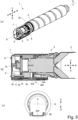
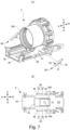
- the developer supply container 1 mainly includes the container body 2, a flange portion 3, the shutter 4, a pump portion 5, a reciprocating member 6, and a cover 7.
- the container body 2 supplies the developer to the developer receiving apparatus 8 by rotating in the developer receiving apparatus 8 in the direction indicated by an arrow R about the rotation axis P shown in part (a) of Figure 5 .
- the direction of the rotation axis P is the same as a rotation axis direction, and is the same as the mounting / dismounting directions parallel with the mounting direction A and the dismounting direction B.
- the container body 2 mainly comprises a developer accommodating portion 2c for containing the developer.
- the container body 2 is provided with a helical feeding groove 2a (feeding portion) for feeding the developer in the developer accommodating portion 2c by rotating the container body 2 in the direction of the arrow R around the rotation axis P.
- the cam groove 2b and the drive receiving portion 2d are integrally formed with the container body 2, but the cam groove 2b or the drive receiving portion 2d may be formed as a separate member and may be integrally mounted to the container body 2.
- a toner having a volume average particle diameter of 5 ⁇ m to 6 ⁇ m is accommodated in the developer accommodating portion 2c as a developer, for example.
- the developer accommodating portion 2c is not only the container body 2, but also internal spaces of the container body 2, a flange portion 3 and the pump portion 5 which will be described later.
- the flange portion 3 is mounted so as to be rotatable relative to the container body 2 about the rotation axis P. And, when the developer supply container 1 is mounted to the developer receiving apparatus 8, the flange portion 3 is held so as not to rotate in the arrow R direction relative to the mounting portion 8f (part (a) of Figure 3 ).
- a container discharge opening 3a4 is provided in a portion of the flange portion 3, and an opening seal 3a5 is mounted to the periphery thereof.
- the flange portion 3 is provided with the pump portion 5, the reciprocating member 6, the shutter 4, and the cover 7.
- the pump portion 5 is threaded at one end side (mounting direction A) of the flange portion 3, and the container body 2 is connected to the other end side (side in the dismounting direction B) with a sealing member (not shown) therebetween.
- a reciprocating member 6 is provided so as to sandwich the pump portion 5, and the engaging projection 6b (parts (a) and (b) of Figure 14 ) provided on the reciprocating member 6 is engaged with the cam groove 2b ( Figure 6 ).
- the flange portion 3 is provided with the shutter 4.
- the flange portion 3 and the shutter 4 constitute a discharge portion 300 for discharging the developer accommodated in the developer accommodating portion 2c out.
- the surface on which the shutter 4 is provided is the bottom side of the flange portion 3, more particularly, the top surface of the bottom portion 3d.
- the cover 7 is integrally assembled so as to cover the whole of the flange portion 3, the shutter 4, the pump portion 5, and the reciprocating member 6 as shown in parts (a) and (b) of Figure 5 .
- the flange portion 3 has a flat bottom portion 3d provided horizontally and an opening portion 3e formed in a substantially central portion of the bottom portion 3d, the opening portion 3e penetrating in a vertical direction.
- the bottom portion 3d slidably supports the shutter 4 at the lower portion.
- the main assembly seal 13 and the receiving opening 11a of the developer receiving portion 11 are displaced in the upward direction U, they pass through the opening portion 3e.
- a pivot shaft 41 projecting outward in the width direction is provided on each of side walls of the flange portion 3 with respect to the widthwise direction of the flange portion 3 perpendicular to the direction of insertion and removal and the vertical direction.
- the first positioning portion 42 is provided on the mounting direction A side of the pivot shaft 41
- the second positioning portion 43 is provided on the side of the pivot shaft 41 in the dismounting direction B.
- the engaging portion 30 is rotatably supported, and the engaging portion 30 is fixed by a snap fit (not shown) for preventing disengagement.
- a pivot shaft 41 is provided in the discharge portion 300 so as to rotatably support the engagement portion 30 in such a position that end portions of the engagement portion 30 are possible to rotate.
- the flange portion 3 is provided with an engaging portion 30 engageable with the engaged portion 11b (part (a) of Figure 3 ) of the developer receiving portion 11.
- Part (c) of Figure 5 is a front view of the developer supply container 1.
- the engaging portion 30 is disposed below a plane H including the rotation axis P. Further, the plane H including the rotation axis P is a horizontal plane, and the engaging portion 30 is disposed below this horizontal plane.
- the engaging portion 30 engages with the engaged portion 11b with the mounting operation of the developer supply container 1 and moves the developer receiving portion 11 in the upward direction U such that the receiving opening 11a communicates with the shutter opening 4j (part (a) of Figure 16 ).
- a developer supply container 1 and the developer receiving portion 11 are connected with each other enable supplying of the developer from the developer supply container 1 to the developer receiving portion 11.
- the engaging portion 30 performs a guiding operation such that the developer receiving portion 11 is displaced in the downward direction D away from the developer supply container 1.
- the engaging portion 30 is provided on each side of the flange portion 3 with respect to the width direction perpendicular to the insertion / extracting direction to the vertical direction.
- the engaging portion 30 is a substantially plate-like member and is provided so as to be able to swing around a pivot shaft 41 between a first position (a first state, a solid line in Figure 8 ) and a second position (a second state, an imaginary line in Figure 8 ).
- the engaging portion 30 swings from the first position to the second position with the mounting operation of the developer supply container 1.
- the engaging portion 30 includes, at a front side, a plate-shaped flat plate portion 31 including a flat engaging surface 33 engageable with the engaged portion 11b on a front side, and a bearing portion 32 formed on the back side and pivotally supported on the pivot shaft 41 so as to be swingable.
- the engaging surface 33 engaging with the engaged portion 11b of the engaging portion 30 is a flat surface.
- the engaging surface 33 of the engaging portion 30 is directed upward (direction U) toward the upstream side in the mounting direction A of the developer supply container 1. That is, the engaging portion 30 has a free end portion 30a (one end portion) on the side remote from the developer accommodating portion 2c in the direction of the rotation axis P and a free end portion 30b (other end portion) on the near side, and in the first position, the free end portion 30a is below the free end portion 30b.
- the engaging portion 30 is inclined with respect to the rotational axis P when it is in the first position.
- the inclination of the engaging portion 30 with respect to the mounting direction A of the engaging surface 33 is smaller than in the first position.
- the engaging surface 33 is substantially parallel with the mounting direction A when the engaging portion 30 comes into contact with a second positioning portion 43. That is, an inclination angle of the engaging portion 30 with respect to the rotation axis P when in the second position is about 0 °.
- the engaging surface 33 is inclined by a predetermined inclination angle ⁇ with respect to the mounting direction A. This inclination angle ⁇ may be, for example, about 30 degrees to 60 degrees.
- a first positioning portion 42 formed on the flange portion 3 abuts against the back side of the free end portion 30a on the mounting direction A side of the engaging portion 30, thereby positioning the engaging portion 30 to the first position. That is, the positioning portion 42 functions as a regulating portion for regulating the rotation of the engaging portion 30.
- the second positioning portion 43 positions the engaging portion 30 at the second position, by the abutting against the back side of the free end portion 30b on the dismounting direction B side of the engaging portion 30.
- the engaging portion 30 is urged by a torsion coil spring (urging portion) 44 so as to contact the first positioning portion 42. That is, the torsion coil spring 44 maintains the first state in which the free end portion 30a is below the free end portion 30b.
- the engaging portion 30 abuts against the first positioning portion 42.
- the engaging portion 30 is positioned on the pivot shaft 41 by a snap fit in the width direction in order not to separate from the pivot shaft 41.
- the engaging portion 30 In a state in which the engaging portion 30 is in contact with the first positioning portion 42, the engaging portion 30 is inclined by the inclination angle ⁇ relative to the mounting direction A of the developer supply container 1 to the developer receiving apparatus 8. Therefore, by inserting the developer supply container 1 into the developer receiving apparatus 8, the engaging portion 30 displaces the developer receiving portion 11 in the upward direction U crossing the mounting direction A of the developer supply container 1 the opening operation of the developer receiving portion 11 in the upward direction U is performed. On the other hand, in a state in which the engaging portion 30 is in contact with the second positioning portion 43, the engaging portion 30 is parallel with the mounting direction A of the developer supply container 1 to the developer receiving apparatus 8.
- the bearing portion 32 pivotally supported by the pivot shaft 41 is provided at the lower side of the flat plate portion 31 slightly upstream in the mounting direction A.
- the pivot shaft 41 is provided between the free end portion (upstream side end portion) 30b on the upstream side of the engaging portion 30 and the free end portion (downstream side end portion) 30a on the downstream side, at the position where the engaging portion 30 swings between the first position and the second position by the engagement of the engaged portion 11b.
- the pivot shaft 41 is disposed below the rotation axis P in the vertical direction and above the shutter opening 4j.
- the pivot shaft 41 is arranged at a position more remote from the developer accommodating portion 2c than the shutter opening 4j in the direction of the rotation axis P.
- the pivot shaft 41 projects from the side surface of the discharge portion 300.
- the position of the bearing portion 32 and the position of the pivot shaft 41 with respect to the flat plate portion 31 can be appropriately selected depending on the structure and size of each portion.
- the shutter 4 slidable on the upper surface of the bottom portion 3d (part (a) of Figure 7 ) of the flange portion 3 move relative to a portion (flange portion 3) of the developer supply container 1.
- the shutter 4 has a shutter opening 4j as a discharge opening, and opens and closes the container discharge opening 3a4 (part (b) in Figure 7 ) of the developer supply container 1 in accordance with the mounting and dismounting operation of the developer supply container 1.
- the receiving opening 11a of the developer receiving portion 11 and the shutter opening 4j communicate with each other, and in addition with the container discharge opening 3a4.
- the developer in the developer supply container 1 can be discharged to the receiving opening 11a.
- the discharge portion 300 (part (b) of Figure 5 ) for discharging the developer is constituted by the flange portion 3 and the shutter 4, and the shutter 4 of the discharge portion 300 is provided in a bottom surface with the shutter opening 4j as the discharge opening for discharging the developer.
- the shutter 4 is provided with a connecting surface 4k connected to the developer receiving portion 11 so as to surround the shutter opening 4j, on the sliding surface 4i opposite to the bottom portion 3d.
- the connecting surface 4k has a larger diameter than the shutter opening 4j and is parallel to the sliding surface 4i.
- a developer sealing portion 4a is provided at a position deviated from the shutter opening 4j of the shutter 4.
- the developer sealing portion 4a closes the container discharge opening 3a4, and as the shutter 4 moves relative to the developer supply container 1 in accordance with the operation of taking out the developer supply container 1.
- the developer sealing portion 4a prevents leakage of the developer from the container discharge opening 3a4, when the developer supply container 1 is not mounted to the mounting portion 8f (part (a) of Figure 3 ) of the developer receiving apparatus 8.
- a sliding surface 4i sliding on the upper surface of the bottom portion 3d of the flange portion 3 is provided on a back surface side (the developer receiving portion 11 side) of the developer sealing portion 4a.
- the shutter 4 is engaged with the flange portion 3 in an attitude in which the developer sealing portion 4a faces upward.
- the shutter 4 is provided with a first stopper portion 4b and a second stopper portion 4c held by first and second shutter stopper portions 8a and 8b (part (a) of Figure 4 ) of the developer receiving apparatus 8 doing so that the developer supply container 1 is capable of moving relative to the shutter 4.
- the shutter 4 is provided with a support portion 4d for displaceably supporting the first and second stopper portions 4b and 4c.
- the support portion 4d is elastically deformable and extends from one side to other side of the developer sealing portion 4a.
- the first stopper portion 4b and the second stopper portion 4c are provided at the free end portion of the support portion 4d.
- first stopper portion 4b is inclined so that an angle ⁇ formed by the first stopper portion 4b and the support portion 4d is an acute angle.
- second stopper portion 4c is inclined so that an angle ⁇ formed by the second stopper portion 4c and the support portion 4d is an obtuse angle.
- the first stopper portion 4b When the developer supply container 1 is mounted, the first stopper portion 4b is engaged with the guide portion 8 g of the developer receiving apparatus 8 and is displaced to pass through the second shutter stopper portion 8b, thus engaging with the first shutter stopper portion 8a. As the first stopper portion 4b and the first shutter stopper portion 8a are engaged with each other, the position of the shutter 4 with respect to the developer receiving apparatus 8 is fixed.
- the second stopper portion 4c is engaged with the second shutter stopper portion 8b of the developer receiving apparatus 8 to release the first stopper portion 4b from the first shutter stopper portion 8a at the time of removing the developer supply container 1. By this, the shutter 4 is dismounted from the developer receiving apparatus 8.
- the pump portion 5 alternately and repeatedly changes the internal pressure of the developer accommodating portion 2c, switching between a state lower than the atmospheric pressure and a state higher than atmospheric pressure by the driving force received by the drive receiving portion 2d of the container body 2 ( Figure 6 ).
- the pump portion 5 is provided at a portion of the developer supply container 1.
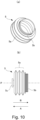
- the pump portion 5 is a displacement type pump in which a volume is changed. More specifically, the pump portion 5 employed in this embodiment has a bellows-like stretchable member capable of expanding and contracting.
- the pressure inside the developer supply container 1 is changed by the expansion and contracting operations of the pump portion 5, and the developer is discharged by utilizing the pressure. More specifically, when the pump portion 5 is contracted, the interior of the developer supply container 1 is brought into a compressed state, and the developer is pushed out to discharge through the container discharge opening 3a4 of the developer supply container 1. In addition, when the pump portion 5 is expanded, the interior of the developer supply container 1 is brought into a reduced pressure state, and the air is taken in from the outside through the container discharge opening 3a4. By air taken in, the developer in the container discharge opening 3a4 and in the neighborhood of the storage portion 3a3 (part (a) in Figure 7 ) that stores the developer transported from the container body 2 of the flange portion 3 is loosened and smoothly discharged.
- the developer in the developer supply container 1 may gather due to vibrations imparted when transporting the developer supply container 1 and so on, with the possible result that the developer is caked in this portion. Therefore, as described above, the air is taken in through the container discharge opening 3a4, so that it is possible to loosen the developer that has been caked.
- the air and the powder as the developer are mixed with the result that the flowability of the developer is enhanced, and therefore, clogging of the developer does not easily occur, as an additional advantage.
- a connecting portion 5b is provided so as to be able to be joined with the flange portion 3 on the opening end side (dismounting direction B).
- screw threads are formed as the connecting portion 5b.
- the pump portion 5 has a reciprocating member engaging portion 5c which engages with the reciprocating member 6, which will be described hereinafter, on the other end side (the mounting direction A side) opposite to the opening end.
- the pump portion 5 has a bellows-shaped expandable portion (bellows portion, expansion and contraction member) 5a in which crests and bottoms are alternately formed periodically.
- the expansion and contraction portion 5a is capable of contracting by moving the reciprocating member engaging portion 5c in the dismounting direction B with respect to the connecting portion 5b along the folding lines (with folding lines as the base point), and is capable of expanding by moving reciprocating member engaging portion 5c in the mounting direction A. Therefore, when the bellows-like pump portion 5 as employed in this embodiment, it is possible to reduce variations in volumetric change with respect to the expansion and contraction amount, and therefore, it is possible to accomplish the stable volumetric change.
- polypropylene resin is used as the material of the pump portion 5, but the present invention is not limited to this example.
- any material may be used as long as it has an expansion and contraction function and is capable of changing the internal pressure of the developer accommodating portion by changing the volume.
- ABS acrylonitrile-butadiene-styrene copolymer
- polystyrene polyester, polyethylene, and so on are usable.
- rubber, other stretchable materials or the like can also be used.
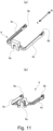
- the reciprocating member 6 In order to change the volume of the pump portion 5, the reciprocating member 6 is provided with a pump engaging portion 6a (part (b) of Figure 13 ) which engages with the reciprocating member engaging portion 5c provided on the pump portion (part (b) of Figure 10 ).
- the reciprocating member 6 is provided with an engaging projection 6b to be engaged with the above-described cam groove 2b ( Figure 6 ) at the time of assembly.
- the engaging projection 6b is provided at the free end portion of the arm 6c extending in the mounting and dismounting direction from the neighborhood of the pump engaging portion 6a.
- the reciprocating member 6 is regulated in rotation around the rotation axis P (part (a) of Figure 5 ) of the arm 6c by the reciprocating member holding portion 7b (part (b) of Figure 12 ) of the cover 7 which will be described hereinafter. Therefore, when the container body 2 is driven by the drive receiving portion 2d by the driving gear 9, and the cam groove 2b rotates integrally, the reciprocating member 6 reciprocates back and forth in the directions A and B by the urging action of the engaging projection 6b fitted in the cam groove 2b and the reciprocating member holding portion 7b of the cover 7. Accordingly, the pump portion 5 engaged with the pump engaging portion 6a of the reciprocating member 6 by way of the reciprocating member engaging portion 5c expands and contracts in the dismounting direction B and the mounting direction A.
- the cover 7 will be described.
- the cover 7 is provided as shown in part (b) of Figure 5 for the purpose of improving the appearance of the developer supply container 1 and protecting the reciprocating member 6 and the pump portion 5.
- the cover 7 is provided so as to cover the entirety of the flange portion 3, the pump portion 5, and the reciprocating member 6.
- the cover 7 is provided with a guide groove 7a to be guided by the insertion guide 8e (part (a) of Figure 3 ) of the developer receiving apparatus 8.
- the cover 7 is provided with a reciprocating member holding portion 7b for restricting rotation of the reciprocating member 6 about the rotation axis P (part (a) of Figure 5 ).
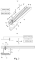
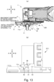
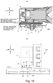
- part (a) and part (b) of Figure 13 illustrate a state before the engaged portion 11b is engaged with the engaging surface 33 when the developer supply container 1 is inserted
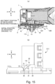
- part (a) and part (b) of Figure 14 illustrate a state when the engaged portion 11b is engaged with the engaging surface 33 as the developer supply container 1 is inserted.
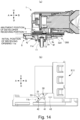
- part (a) and part (b) of Figure 15 illustrate a state immediately before the engaging portion 30 swings as the developer supply container 1 is inserted
- part (a) and part (b) of Figure 16 illustrate a state after the engaging portion 30 is pivoted to the second position in accordance with completion of mounting of the developer supply container 1.
- the developer supply container 1 is inserted into the image forming apparatus 100, and as shown in part (a) of Figure 13 , the developer supply container 1 is moved in the mounting direction A.
- the engaging portion 30 and the engaged portion 11b have not yet engaged.
- the container discharge opening 3a4 is sealed by the developer sealing portion 4a of the shutter 4.
- stopper portions 4b, 4c are engaged with shutter stopper portions 8a, 8b of the developer receiving apparatus 8, and the position of the shutter 4 in the mounting direction A is fixed relative to the developer receiving apparatus 8. Therefore, after this, even if the developer supply container 1 is moved in the mounting direction A in the mounting direction A, the shutter 4 moves relative to the developer supply container 1 except the shutter 4, but does not move relative to the developer receiving portion 11 in the insertion / removal direction.
- the engaged portion 11b rises along the engaging surface 33 of the engaging portion 30 and is displaced in the upper direction U side from the pivot shaft 41.
- the engaging portion 30 swings about the pivot shaft 41 in the clockwise direction in the Figure. And, the engaging portion 30 abuts to the second positioning portion 43, so that the engaging portion 30 becomes horizontal with respect to the mounting direction A (part (b) of Figure 16 ).
- the receiving opening 11a and the shutter opening 4j move relative to the flange portion 3, while they are in contact with each other while to become in fluid communication with the container discharge opening 3a4.
- the container outlet 3a4, the shutter opening 4j and the receiving opening 11a communicate with each other, and therefore, it is possible to supply the developer from the developer supply container 1 to the developer receiving apparatus 8.
- the engaging portion 30 is parallel to the mounting direction A of the developer supply container 1.
- the developer receiving portion 11 including the engaged portion 11b is not lifted beyond the state in contact with the shutter 4, and no excessive force is applied to the engaged portion 11b and the like.
- the positional relationship between the container outlet 3a4 and the engaging surface 33 is such that a plane L which passes through the container discharge opening 3a4 and perpendicular to the rotation axis P passes through the engaging surface 33.
- the plane including the engaging surface 33 is disposed between the rotation axis P and the container discharge opening 3a4. Further, the position of the plane L in the direction of the rotation axis P is on the side of the developer accommodating portion 2c with respect to the pivot shaft 41.
- the engaged portion 11b is displaced along the engaging surface 33 of the engaging portion 30 at all times.
- the engaged portion 11b contacts with the inclined engaging surface 33 for lifting the engaged portion 11b in the upward direction U at the time of starting insertion of the developer supply container 1, and with the horizontal engaged surface for maintaining the height of the engaged portion 11b when the developer supply container 1 is completely inserted.
- the engaging surface does not suddenly change as in the case where the inclined engaging surface and the horizontal engaging surface are two flat folded surfaces, and the switching between the inclined engaging surface 33 and the horizontal engaging surface 33 can be smooth.
- the engaging surface 33 is planar, and therefore, The complication of the shape of the engaging portion 30 can be suppressed.
- the engaging surface 33 of the engaging portion 30 is made flat but the present invention is not limited to this example.
- the engaging surface 33 may have a curved surface shape.
- the engaging surface 33 is parallel to the mounting direction A, but, the present invention is not limited to this example.
- the engaging surface 33 may be provided so as to incline in the mounting direction A.
- a developer receiving apparatus withdrawing device is provided.
- the developer supply container 1 is fixed to a predetermined mounting position in a state of being drawn in the mounting direction by the retracting device, and therefore, The developer supply container 1 will not move in the dismounting direction unless an operator intentionally removes it by applying force. Therefore, even if the engaging surface 33 is not a parallel surface, the engaged portion 11b will not unintentionally move in the dismounting direction B.
- the shutter opening 4j of the shutter 4 is the discharge opening with which the receiving opening 11a of the developer receiving portion 11 communicates
- the present invention is not limited to this example.
- the receiving opening of the developer receiving portion may be brought into direct contact with the container discharge opening of the developer supply container 1 without providing a shutter, so that these members communicate with each other.
- the container discharge opening corresponds to the discharge opening communicating with the receiving opening.
- a developer supply container and a developer supplying system capable of improving operability by reducing operating force when mounting a developer supply container.
Abstract
Description
- The present invention relates to a developer supply container dismountably mountable to a developer receiving apparatus and a developer supplying system.
- Conventionally, in electrophotographic image forming apparatuses such as copying machines, fine developing powder such as toner has been used. In such an image forming apparatus, the developer consumed by the image formation is supplemented from a developer supply container.
- For example, a structure has been proposed in which the developer supply container is mountable to and dismountable from a developer receiving apparatus provided in the image forming apparatus, and the developer receiving portion of the developer receiving apparatus is displaced toward the discharge opening of the developer supply container in accordance with the mounting operation of the developer supply container (
JP2013 - 015826A - An object of the present invention is to provide a developer supply container and a developer supplying system capable of improving easiness of operation by reducing the operation force when mounting the developer supply container.
- According to an aspect of the present invention, there is provided a developer supply container detachably mountable to a developer receiving apparatus, the developer receiving apparatus including a receiving opening for receiving a developer, and a portion-to-be-engaged integrally displaceable with the developer receiving portion, said developer supply container comprising a rotatable developer accommodating portion accommodating the developer; a gear for transmitting a driving force to said developer accommodating portion; a developer discharging portion rotatable relative to said developer accommodating portion and provided at a bottom side with a discharge opening for discharging the developer from said developer accommodating portion; a rotatable engaging portion engageable with the portion-to-be-engaged with a mounting operation of said developer supply container to displace the developer receiving portion so as to move the receiving opening toward said discharge opening, thus bring the receiving opening in fluid communication with said discharge opening; a shaft portion which is provided between one end portion of said engaging portion and other end portion thereof with respect to a rotational axis direction of said developer accommodating portion and which rotatably supports said engageable member; and a restricting portion for restricting movement of a gear side end portion of said engaging portion with respect to the rotational axis direction beyond a predetermined position.
- According to the present invention, it is possible to improve the operativity by reducing the operating force when mounting the developer supply container.
-
-
Figure 1 is a schematic structure illustration of an image forming apparatus according to an embodiment of the present invention. -
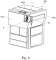
Figure 2 is a perspective view of the image forming apparatus according to the embodiment. -
Figure 3 illustrates a developer receiving apparatus according to the embodiment, wherein part (a) thereof is a perspective view, and part (b) is a cross-sectional view thereof. -
Figure 4 illustrates the developer receiving apparatus according to the embodiment, and part (a) thereof is an enlarged perspective view, part (b) thereof is an enlarged sectional view, and part (c) is a perspective view of the developer receiving portion. -
Figure 5 is a perspective view of a developer supply container according to the embodiment, wherein part (a) is a partial cut perspective view, part (b) thereof is a cross-sectional view around a flange portion, and part (c) thereof is a front view seen from the front. -
Figure 6 is a perspective view of a container body of the developer supply container according to the embodiment. -
Figure 7 illustrates a flange portion according to the embodiment, wherein part (a) thereof is a perspective view, and part (b) thereof is a bottom view. -
Figure 8 is a side view of an engaging portion according to the embodiment. -
Figure 9 illustrates a shutter according to the embodiment, wherein part (a) thereof is a top view, and part (b) thereof is a perspective view. -
Figure 10 shows a pump according to the embodiment, wherein part (a) thereof is a perspective view, and part (b) thereof is a side view. -
Figure 11 illustrates a reciprocating member according to the embodiment, wherein part (a) thereof is a perspective view, and part (b) thereof is a perspective view seen from the opposite side of part (a). -
Figure 12 illustrates a cover according to the embodiment, wherein part (a) thereof is a perspective view, and part (b) thereof is a perspective view from the opposite side of part (a). -
Figure 13 illustrates a state before an engaged portion is engaged with an engaging surface when the developer supply container according to the embodiment is inserted, wherein part (a) thereof is a side view of a connecting portion between a shutter opening and a receiving port, and part (b) thereof is a side view of a flange. -
Figure 14 illustrates a state when the engaged portion is engaged with the engaging surface in accordance with the insertion of the developer supply container according to the embodiment, wherein part (a) the end of is a side view of the connection portion between the shutter opening and the receiving port, and part (b) thereof is a side view of the flange. -
Figure 15 shows a state immediately before when the engaging portion swings as the developer supply container according to the embodiment is inserted, wherein part (a) thereof is a side view of the connection portion between the shutter opening and the receiving port, and part (b) thereof is a side view of the flange. -
Figure 16 illustrates a state after the engaging portion has swung to the second position in accordance with completion of mounting of the developer supply container according to the embodiment, wherein part (a) thereof is a side view of the connection portion between the shutter opening and the receiving port, and part (b) thereof is a side view of the flange. - In the following, referring to part (b) of
Figures 1 to 16 , an embodiment of the present invention will be described. First, referring toFigure 1 andFigure 2 , the schematic structure of the image forming apparatus of the embodiment will be described. - In
Figure 1 , theimage forming apparatus 100 includes anoriginal reading device 103 at a top of amain assembly 100a of the image forming apparatus. An original 101 is placed on anoriginal platen glass 102. A light image corresponding to image information of the original 101 is imaged, using a plurality of mirrors M and the lens Ln of theoriginal reading device 103, on aphotosensitive drum 104 which is a cylindrical photosensitive member as an image bearing member to form an electrostatic latent image. This electrostatic latent image is visualized using toner (one component magnetic toner) as a developer (dry powder) by a dry type developing device (one-component developing device) 201. Here, in this embodiment, a one-component magnetic toner is used as the developer to be supplied from the developer supply container 1 (also referred to as a toner cartridge), but the present invention is not limited to such an example, and it may be of a structure as will be described hereinafter. - More specifically, in the case of using a one-component developing device which performs developing operation with one component nonmagnetic toner, one component nonmagnetic toner is supplied as a developer. In addition, non-magnetic toner is supplied as the developer when using a two-component developer which develops the image using a two component developer prepared by mixing magnetic carrier and nonmagnetic toner. In this case, as the developer, a structure may be employed in which the magnetic carrier is also supplied together with the non-magnetic toner.
- As described above, a developing
device 201 shown inFigure 1 develops the electrostatic latent image formed on thephotosensitive drum 104 using the toner as the developer based on the image information of the original 101. In addition, adeveloper supplying system 200 is connected to developingdevice 201, and thedeveloper supplying system 200 includes adeveloper supply container 1 and adeveloper receiving apparatus 8 relative to which thedeveloper supply container 1 is mountable and dismountable.Developer supplying system 200 will be described hereinafter. - The developing
device 201 includes adeveloper hopper portion 201a and a developingroller 201f. In this developer hopperportion 201a, a stirringmember 201c for stirring the developer supplied from thedeveloper supply container 1 is provided. The developer stirred by the stirringmember 201c is fed to a feeding member (201e) side by afeeding member 201d. And, the developer which has been sequentially fed by thefeeding members roller 201f and finally supplied to a developing zone formed with thephotosensitive drum 104. In this embodiment, a single component developer is used, and therefore, the toner as the developer is supplied from thedeveloper supply container 1 to the developingdevice 201. However, in the case of using a two-component developer, it is possible to supply a mixture of the toner and the carrier as the developer from thedeveloper supply container 1. -
Cassettes 105 to 108 contain recording materials S such as sheets of paper. When an image is to be formed, a cassette containing an optimum recording material S among the sheets contained in thesecassettes 105 to 108 is selected on the basis of the information inputted by the operator (user) on theoperation portion 100d (Figure 2 ) of theimage forming apparatus 100 or on the basis of the size of the original 101. Here, as for the recording material S, it is not limited to sheets of paper, but it may be an OHP sheet or the like as the case may be. One sheet of recording material S fed by the feeding and separatingdevices 105A to 108A is fed toregistration rollers 110 by way of afeeding portion 109. Then, the recording material S is fed in synchronization with the rotation of thephotosensitive drum 104 and the scan timing of theoriginal reading device 103. - A
transfer charging device 111 and aseparation charging device 112 are provided at positions opposing thephotosensitive drum 104 on a downstream side of theregistration roller 110 in the recording material feeding direction. The image of the developer (toner image) formed on thephotosensitive drum 104 is transferred onto the recording material S fed by theregistration roller 110, by atransfer charging device 111. And, the recording material S onto which the toner image is transferred is separated from thephotosensitive drum 104 by aseparation charging device 112. Subsequently, heat and pressure are applied to the recording material S fed by thefeeding portion 113 in afixing portion 114, so that the toner image is fixed on the recording material. Thereafter, the recording material S to which the toner image is fixed passes through a discharge/reversingportion 115 and is discharged to thedischarge tray 117 by thedischarge roller 116, in case of single-sided copy. - On the other hand, in case of double - sided copy, the recording material S passes through the discharge/reversing
portion 115, and the recording material S is partly discharged to the outside of the apparatus once by thedischarge roller 116. After this, at the timing when a trailing end of the recording material S passes through theswitching member 118 and is still nipped by thedischarge rollers 116, the position of theswitching member 118 is switched, and thedischarge roller 116 is rotated counterclockwise, by which the recording material S is fed again into the apparatus. Thereafter, the recording material S is fed to theregistration roller 110 by way of the re-feeding and feedingportions discharge tray 117 by way of the same path as in the case of single-sided copying. - In the
image forming apparatus 100 having the above-described structure, image forming process devices such as a developingdevice 201, acleaner portion 202, aprimary charging device 203 and the like are provided around thephotosensitive drum 104. Here, the developingdevice 201 supplies the developer to the electrostatic latent image formed on thephotosensitive drum 104 on the basis of the image information of the original 101 read by theoriginal reading device 103 so as to develop the electrostatic latent image. In addition, theprimary charging device 203 uniformly charges the surface of the photosensitive drum to form a desired electrostatic latent image on thephotosensitive drum 104. Furthermore, thecleaner portion 202 has a function of removing the developer remaining on thephotosensitive drum 104. - As shown in
Figure 2 , when the operator opens areplacement cover 40 which is a portion of an outer cover of the apparatusmain assembly 100a of theimage forming apparatus 100, a part of thedeveloper receiving apparatus 8 which will be described hereinafter can be seen. And, by inserting thedeveloper supply container 1 into thisdeveloper receiving apparatus 8, thedeveloper supply container 1 is mounted in a state where it can supply the developer to thedeveloper receiving apparatus 8. On the other hand, when the operator exchanges thedeveloper supply container 1, it carries out the operation opposite to the loading operation, by which thedeveloper supply container 1 is dismounted from thedeveloper receiving apparatus 8, and thereafter a newdeveloper supply container 1 can be mounted. Here, thereplacement cover 40 is a cover exclusively for mounting/dismounting (exchanging) thedeveloper supply container 1, and is opened and closed only for dismounting/mounting thedeveloper supply container 1. On the other hand, the maintenance operation for theimage forming apparatus 100 is performed by opening/closing afront cover 100c. Here, thereplacement cover 40 and thefront cover 100c may be integrated. In such a case, the replacement of thedeveloper supply container 1 and the maintenance of theimage forming apparatus 100 are performed by opening and closing the integrated cover (not shown). - Next, referring to part (a) of
Figure 3 to part (c) ofFigure 4 , thedeveloper receiving apparatus 8 constituting thedeveloper supplying system 200 will be described. As shown in part (a) ofFigure 3 , thedeveloper receiving apparatus 8 is provided with a mounting portion (mounting space) 8f to which thedeveloper supply container 1 is dismountably mounted. The mountingportion 8f is provided with aninsertion guide 8e for guiding thedeveloper supply container 1 in the mounting and dismounting directions. In the case of this embodiment, the structure is such that the dismounting direction B of thedeveloper supply container 1 is opposite to the direction A of mounting thedeveloper supply container 1 by theinsertion guide 8e. - As shown in part (a) of
Figure 3 to part (a) ofFigure 4 , thedeveloper receiving apparatus 8 has adriving gear 9 which functions as a driving mechanism for driving thedeveloper supply container 1. A rotational driving force is transmitted to thegear 9 from a drivingmotor 500 by way of a driving gear train (not shown), so that thegear 9 applies the rotational driving force to thedeveloper supply container 1 mounted in the mountingportion 8 f. The operation of the drivingmotor 500 is controlled by thecontrol device 600. - In addition to controlling the driving
motor 500, thecontrol device 600 controls overall of theimage forming apparatus 100. Thecontrol device 600 has a CPU (Central Processing Unit), a ROM (Read Only Memory), and a RAM (Random Access Memory). The CPU controls each portion while reading the program corresponding to a control procedure stored in the ROM. In addition, working data and an input data are stored in the RAM, and the CPU executes control while looking up the data stored in the RAM on the basis of the program etc. - In the mounting
portion 8f of thedeveloper receiving apparatus 8, there is provided adeveloper receiving portion 11 for receiving the developer discharged out of thedeveloper supply container 1. Thedeveloper receiving portion 11 is connected to a container discharge opening 3a4 (part (a) ofFigure 16 ) of thedeveloper supply container 1 when thedeveloper supply container 1 is mounted, and has a receivingopening 11a for receiving the developer discharged through the container discharge opening 3a4. Thedeveloper receiving portion 11 is mounted so as to be movable (displaceable) in the direction in which the receivingopening 11a moves toward and away from the container discharge opening 3a4 (in this embodiment, the direction crossing with the direction A in which thedeveloper supply container 1 is mounted (more specifically, vertical direction relative to the developer receiving apparatus 8)). As shown in part (b) ofFigure 3 , in the case of this embodiment, thedeveloper receiving portion 11 is urged by an urgingmember 12, including a helical compression coil spring, for example, in such a direction that the receivingopening 11a moves away from the container discharge opening 3a4 (vertically downward, reverse direction to a direction of displacement). Therefore, thedeveloper receiving portion 11 moves against the urging force of the urgingmember 12 when the receivingopening 11a moves toward the container discharge opening 3a4 (upward in the vertical direction). Here, in the present specification, the direction in which thedeveloper receiving portion 11 displaces in accordance with the mounting operation of thedeveloper supply container 1 is an upward direction in the vertical direction. This direction is called upward (displacing direction, upward in the vertical direction) U, and the downward vertical direction in the opposite direction is called the downward direction D. - In addition, as shown in part (a) of
Figure 4 , in the mountingportion 8f of thedeveloper receiving apparatus 8, a firstshutter stopper portion 8a and a secondshutter stopper portion 8b are provided on the upstream side of thedeveloper receiving portion 11 in the mounting direction A. In thedeveloper supply container 1 which is moving relative to thedeveloper receiving apparatus 8 during mounting/dismounting, the first and secondshutter stopper portions Figure 5 ) which will be described hereinafter relative to thedeveloper receiving apparatus 8. In this case, theshutter 4 moves relative to a part of thedeveloper supply container 1 other than theshutter 4, such as thecontainer body 2 described hereinafter. - As shown in part (b) of
Figure 3 and part (b) ofFigure 4 , below, in the downward direction D, of thedeveloper receiving apparatus 8, there is provided a sub-hopper 8c for temporarily storing the developer supplied from thedeveloper supply container 1. Inside the sub-hopper 8c, there are provided afeeding screw 14 for feeding the developer to thedeveloper hopper portion 201a (Figure 1 ) which is a portion of the developingdevice 201, and anopening 8d communicating with thedeveloper hopper portion 201a. - As shown in part (c) of
Figure 4 , thedeveloper receiving portion 11 is provided with amain assembly seal 13 formed so as to surround the receivingopening 11a. Themain assembly seal 13 is made of elastic material, foam or the like. As shown in part (a) ofFigure 16 , in the state that thedeveloper supply container 1 is mounted, themain assembly seal 13 is in close contact with an opening seal 3a5 surrounding the container discharge opening 3a4 of thedeveloper supply container 1, with theshutter 4 described hereinafter sandwiched therebetween. By this, the developer discharged through the container discharge opening 3a4 of thedeveloper supply container 1 to the receivingopening 11a by way of the shutter opening (discharge port) 4j of theshutter 4 does not leak out of the receivingopening 11a which is a part of the developer feeding passage. That is, themain assembly seal 13 is provided around the receivingopening 11a, and when the communication between the receivingopening 11a and theshutter opening 4j is established, the sealing is performed by elastic deformation between the receivingopening 11a and theshutter opening 4j. - Here, it is desirable that a diameter of the receiving
opening 11a is substantially the same as or slightly larger than a diameter of theshutter opening 4j of theshutter 4, in order to prevent the interior of the mountingportion 8f from being contaminated by the developer. This is because if the diameter of the receivingopening 11a is smaller than the diameter of theshutter opening 4j, the developer discharged from theshutter opening 4j is more likely to be deposited on the upper surface of themain assembly seal 13. If the developer is deposited on the lower surface of thedeveloper supply container 1 at the time of mounting/dismounting operation of thedeveloper supply container 1, it becomes a cause of contamination by the developer. In view of this point, it is preferable that the diameter of the receivingopening 11a is roughly the same as or about 2 mm larger than the diameter of theshutter opening 4j. For example, in the case that the diameter of theshutter opening 4j of theshutter 4 is a fine hole (pinhole) of about 2 mm in diameter, it is preferable that the diameter of the receivingopening 11a is about 3 mm. - In addition, as shown in part (c) of
Figure 4 , on the side surface of thedeveloper receiving portion 11, an engaged portion (portion to be engaged) 11b projecting toward the center side is provided. In the case of this embodiment, the engagedportion 11b is directly engaged with the engaging portion 30 (part (a) inFigure 7 ) provided in thedeveloper supply container 1 which will be described hereinafter, and is guided by the engagingportion 30, by which thedeveloper receiving portion 11 is lifted toward thedeveloper supply container 1 in the upward direction U. - Next, referring to part (a)
Figure 5 to part (b) ofFigure 15 , thedeveloper supply container 1 constituting thedeveloper supplying system 200 will be described. First, referring to part (a) ofFigure 5 and part (b) ofFigure 5 , the overall structure of thedeveloper supply container 1 will be described. Thedeveloper supply container 1 mainly includes thecontainer body 2, aflange portion 3, theshutter 4, apump portion 5, a reciprocatingmember 6, and acover 7. Thecontainer body 2 supplies the developer to thedeveloper receiving apparatus 8 by rotating in thedeveloper receiving apparatus 8 in the direction indicated by an arrow R about the rotation axis P shown in part (a) ofFigure 5 . In the following, each element constituting thedeveloper supply container 1 will be described in detail. Here, in this embodiment, the direction of the rotation axis P is the same as a rotation axis direction, and is the same as the mounting / dismounting directions parallel with the mounting direction A and the dismounting direction B. - As shown in
Figure 6 , thecontainer body 2 mainly comprises adeveloper accommodating portion 2c for containing the developer. In addition, thecontainer body 2 is provided with ahelical feeding groove 2a (feeding portion) for feeding the developer in thedeveloper accommodating portion 2c by rotating thecontainer body 2 in the direction of the arrow R around the rotation axis P. Here, in this embodiment, thecam groove 2b and thedrive receiving portion 2d are integrally formed with thecontainer body 2, but thecam groove 2b or thedrive receiving portion 2d may be formed as a separate member and may be integrally mounted to thecontainer body 2. In addition, in this embodiment, a toner having a volume average particle diameter of 5 µm to 6 µm is accommodated in thedeveloper accommodating portion 2c as a developer, for example. In addition, in this embodiment, thedeveloper accommodating portion 2c is not only thecontainer body 2, but also internal spaces of thecontainer body 2, aflange portion 3 and thepump portion 5 which will be described later. - Referring to part (a) of
Figure 5 , part (b) ofFigure 5 , part (a) ofFigure 7 and part (b) ofFigure 7 , theflange portion 3 will be described. Theflange portion 3 is mounted so as to be rotatable relative to thecontainer body 2 about the rotation axis P. And, when thedeveloper supply container 1 is mounted to thedeveloper receiving apparatus 8, theflange portion 3 is held so as not to rotate in the arrow R direction relative to the mountingportion 8f (part (a) ofFigure 3 ). In addition, as shown in part (b) ofFigure 7 , a container discharge opening 3a4 is provided in a portion of theflange portion 3, and an opening seal 3a5 is mounted to the periphery thereof. As shown in part (b) ofFigure 5 , theflange portion 3 is provided with thepump portion 5, the reciprocatingmember 6, theshutter 4, and thecover 7. - First, the
pump portion 5 is threaded at one end side (mounting direction A) of theflange portion 3, and thecontainer body 2 is connected to the other end side (side in the dismounting direction B) with a sealing member (not shown) therebetween. In addition, a reciprocatingmember 6 is provided so as to sandwich thepump portion 5, and the engagingprojection 6b (parts (a) and (b) ofFigure 14 ) provided on the reciprocatingmember 6 is engaged with thecam groove 2b (Figure 6 ). Theflange portion 3 is provided with theshutter 4. In this embodiment, theflange portion 3 and theshutter 4 constitute adischarge portion 300 for discharging the developer accommodated in thedeveloper accommodating portion 2c out. In addition, the surface on which theshutter 4 is provided is the bottom side of theflange portion 3, more particularly, the top surface of thebottom portion 3d. In order to improve an outer appearance and to protect the reciprocatingmember 6 and pumpportion 5, thecover 7 is integrally assembled so as to cover the whole of theflange portion 3, theshutter 4, thepump portion 5, and the reciprocatingmember 6 as shown in parts (a) and (b) ofFigure 5 . - In addition, as shown in parts (a) and (b) of
Figure 7 , theflange portion 3 has aflat bottom portion 3d provided horizontally and anopening portion 3e formed in a substantially central portion of thebottom portion 3d, theopening portion 3e penetrating in a vertical direction. As shown in part (b) ofFigure 5 , thebottom portion 3d slidably supports theshutter 4 at the lower portion. As shown in part (a) ofFigure 15 , when themain assembly seal 13 and the receivingopening 11a of thedeveloper receiving portion 11 are displaced in the upward direction U, they pass through theopening portion 3e. - As shown in part (a) of
Figure 7 , on each of side walls of theflange portion 3 with respect to the widthwise direction of theflange portion 3 perpendicular to the direction of insertion and removal and the vertical direction, apivot shaft 41 projecting outward in the width direction is provided. In addition, in the wall portions of theflange portion 3, thefirst positioning portion 42 is provided on the mounting direction A side of thepivot shaft 41, and thesecond positioning portion 43 is provided on the side of thepivot shaft 41 in the dismounting direction B. On thepivot shaft 41, the engagingportion 30 is rotatably supported, and the engagingportion 30 is fixed by a snap fit (not shown) for preventing disengagement. Apivot shaft 41 is provided in thedischarge portion 300 so as to rotatably support theengagement portion 30 in such a position that end portions of theengagement portion 30 are possible to rotate. - As shown in part (a) of
Figure 7 , theflange portion 3 is provided with an engagingportion 30 engageable with the engagedportion 11b (part (a) ofFigure 3 ) of thedeveloper receiving portion 11. Part (c) ofFigure 5 is a front view of thedeveloper supply container 1. As shown in part (c) ofFigure 5 , the engagingportion 30 is disposed below a plane H including the rotation axis P. Further, the plane H including the rotation axis P is a horizontal plane, and the engagingportion 30 is disposed below this horizontal plane. The engagingportion 30 engages with the engagedportion 11b with the mounting operation of thedeveloper supply container 1 and moves thedeveloper receiving portion 11 in the upward direction U such that the receivingopening 11a communicates with theshutter opening 4j (part (a) ofFigure 16 ). At this time, adeveloper supply container 1 and thedeveloper receiving portion 11 are connected with each other enable supplying of the developer from thedeveloper supply container 1 to thedeveloper receiving portion 11. In addition, in order to break the connection state between thedeveloper supply container 1 and thedeveloper receiving portion 11 with the takeout operation of thedeveloper supply container 1, the engagingportion 30 performs a guiding operation such that thedeveloper receiving portion 11 is displaced in the downward direction D away from thedeveloper supply container 1. Here, as shown in parts (a) and (b) ofFigure 7 , in this embodiment, the engagingportion 30 is provided on each side of theflange portion 3 with respect to the width direction perpendicular to the insertion / extracting direction to the vertical direction. - As shown in part (a) of
Figure 7 andFigure 8 , the engagingportion 30 is a substantially plate-like member and is provided so as to be able to swing around apivot shaft 41 between a first position (a first state, a solid line inFigure 8 ) and a second position (a second state, an imaginary line inFigure 8 ). The engagingportion 30 swings from the first position to the second position with the mounting operation of thedeveloper supply container 1. The engagingportion 30 includes, at a front side, a plate-shapedflat plate portion 31 including a flatengaging surface 33 engageable with the engagedportion 11b on a front side, and a bearingportion 32 formed on the back side and pivotally supported on thepivot shaft 41 so as to be swingable. The engagingsurface 33 engaging with the engagedportion 11b of the engagingportion 30 is a flat surface. - As indicated by the solid line in
FIG 8 , at the first position of the engagingportion 30, the engagingsurface 33 of the engagingportion 30 is directed upward (direction U) toward the upstream side in the mounting direction A of thedeveloper supply container 1. That is, the engagingportion 30 has afree end portion 30a (one end portion) on the side remote from thedeveloper accommodating portion 2c in the direction of the rotation axis P and afree end portion 30b (other end portion) on the near side, and in the first position, thefree end portion 30a is below thefree end portion 30b. In addition, the engagingportion 30 is inclined with respect to the rotational axis P when it is in the first position. In addition, as shown in phantom lines inFigure 8 , at the second position of the engagingportion 30, the inclination of the engagingportion 30 with respect to the mounting direction A of the engagingsurface 33 is smaller than in the first position. In this embodiment, at the second position of the engagingportion 30, the engagingsurface 33 is substantially parallel with the mounting direction A when the engagingportion 30 comes into contact with asecond positioning portion 43. That is, an inclination angle of the engagingportion 30 with respect to the rotation axis P when in the second position is about 0 °. In the first position of the engagingportion 30, the engagingsurface 33 is inclined by a predetermined inclination angle θ with respect to the mounting direction A. This inclination angle θ may be, for example, about 30 degrees to 60 degrees. - In addition, a
first positioning portion 42 formed on theflange portion 3 abuts against the back side of thefree end portion 30a on the mounting direction A side of the engagingportion 30, thereby positioning the engagingportion 30 to the first position. That is, the positioningportion 42 functions as a regulating portion for regulating the rotation of the engagingportion 30. Thesecond positioning portion 43 positions the engagingportion 30 at the second position, by the abutting against the back side of thefree end portion 30b on the dismounting direction B side of the engagingportion 30. The engagingportion 30 is urged by a torsion coil spring (urging portion) 44 so as to contact thefirst positioning portion 42. That is, thetorsion coil spring 44 maintains the first state in which thefree end portion 30a is below thefree end portion 30b. Therefore, when thedeveloper supply container 1 is inserted into theimage forming apparatus 100, the engagingportion 30 abuts against thefirst positioning portion 42. Here, the engagingportion 30 is positioned on thepivot shaft 41 by a snap fit in the width direction in order not to separate from thepivot shaft 41. - In a state in which the engaging
portion 30 is in contact with thefirst positioning portion 42, the engagingportion 30 is inclined by the inclination angle θ relative to the mounting direction A of thedeveloper supply container 1 to thedeveloper receiving apparatus 8. Therefore, by inserting thedeveloper supply container 1 into thedeveloper receiving apparatus 8, the engagingportion 30 displaces thedeveloper receiving portion 11 in the upward direction U crossing the mounting direction A of thedeveloper supply container 1 the opening operation of thedeveloper receiving portion 11 in the upward direction U is performed. On the other hand, in a state in which the engagingportion 30 is in contact with thesecond positioning portion 43, the engagingportion 30 is parallel with the mounting direction A of thedeveloper supply container 1 to thedeveloper receiving apparatus 8. In addition, in this embodiment, in a state in which the engagingportion 30 is in contact with thesecond positioning portion 43, the engagingportion 30 is parallel to the rotation axis P and parallel to the horizontal plane. Therefore, while thedeveloper supply container 1 moves relative to the container discharge opening 3a4, that is, while the receivingopening 11a moves to the position where it connects with the container outlet 3a4, themain assembly seal 13 and theshutter opening 4j are kept connected (part (a) ofFigure 16 ). - In addition, in this embodiment, the bearing
portion 32 pivotally supported by thepivot shaft 41 is provided at the lower side of theflat plate portion 31 slightly upstream in the mounting direction A. With respect to the mounting direction A, thepivot shaft 41 is provided between the free end portion (upstream side end portion) 30b on the upstream side of the engagingportion 30 and the free end portion (downstream side end portion) 30a on the downstream side, at the position where the engagingportion 30 swings between the first position and the second position by the engagement of the engagedportion 11b. In addition, thepivot shaft 41 is disposed below the rotation axis P in the vertical direction and above theshutter opening 4j. In addition, thepivot shaft 41 is arranged at a position more remote from thedeveloper accommodating portion 2c than theshutter opening 4j in the direction of the rotation axis P. Thepivot shaft 41 projects from the side surface of thedischarge portion 300. However, the position of the bearingportion 32 and the position of thepivot shaft 41 with respect to theflat plate portion 31 can be appropriately selected depending on the structure and size of each portion. - Next, referring to parts (a) and (b) of
Figure 12 theshutter 4 will be described. Theshutter 4 slidable on the upper surface of thebottom portion 3d (part (a) ofFigure 7 ) of theflange portion 3 move relative to a portion (flange portion 3) of thedeveloper supply container 1. Theshutter 4 has ashutter opening 4j as a discharge opening, and opens and closes the container discharge opening 3a4 (part (b) inFigure 7 ) of thedeveloper supply container 1 in accordance with the mounting and dismounting operation of thedeveloper supply container 1. That is, by moving theshutter 4 relative to thedeveloper supply container 1 in accordance with the mounting operation of thedeveloper supply container 1, the receivingopening 11a of thedeveloper receiving portion 11 and theshutter opening 4j communicate with each other, and in addition with the container discharge opening 3a4. By this, the developer in thedeveloper supply container 1 can be discharged to the receivingopening 11a. That is, the discharge portion 300 (part (b) ofFigure 5 ) for discharging the developer is constituted by theflange portion 3 and theshutter 4, and theshutter 4 of thedischarge portion 300 is provided in a bottom surface with theshutter opening 4j as the discharge opening for discharging the developer. - In addition, the
shutter 4 is provided with a connectingsurface 4k connected to thedeveloper receiving portion 11 so as to surround theshutter opening 4j, on the slidingsurface 4i opposite to thebottom portion 3d. The connectingsurface 4k has a larger diameter than theshutter opening 4j and is parallel to the slidingsurface 4i. After mounting thedeveloper supply container 1, the upper end surface of themain assembly seal 13 is brought into close contact with the connectingsurface 4k. - On the other hand, as shown in parts (a) and (b) of
Figure 12 , adeveloper sealing portion 4a is provided at a position deviated from theshutter opening 4j of theshutter 4. Thedeveloper sealing portion 4a closes the container discharge opening 3a4, and as theshutter 4 moves relative to thedeveloper supply container 1 in accordance with the operation of taking out thedeveloper supply container 1. In addition, thedeveloper sealing portion 4a prevents leakage of the developer from the container discharge opening 3a4, when thedeveloper supply container 1 is not mounted to the mountingportion 8f (part (a) ofFigure 3 ) of thedeveloper receiving apparatus 8. A slidingsurface 4i sliding on the upper surface of thebottom portion 3d of theflange portion 3 is provided on a back surface side (thedeveloper receiving portion 11 side) of thedeveloper sealing portion 4a. Here, theshutter 4 is engaged with theflange portion 3 in an attitude in which thedeveloper sealing portion 4a faces upward. - The
shutter 4 is provided with afirst stopper portion 4b and asecond stopper portion 4c held by first and secondshutter stopper portions Figure 4 ) of thedeveloper receiving apparatus 8 doing so that thedeveloper supply container 1 is capable of moving relative to theshutter 4. In addition, theshutter 4 is provided with asupport portion 4d for displaceably supporting the first andsecond stopper portions support portion 4d is elastically deformable and extends from one side to other side of thedeveloper sealing portion 4a. And, thefirst stopper portion 4b and thesecond stopper portion 4c are provided at the free end portion of thesupport portion 4d. By this, the first andsecond stopper portions support portion 4d. - Here, the
first stopper portion 4b is inclined so that an angle α formed by thefirst stopper portion 4b and thesupport portion 4d is an acute angle. On the contrary, thesecond stopper portion 4c is inclined so that an angle β formed by thesecond stopper portion 4c and thesupport portion 4d is an obtuse angle. - When the
developer supply container 1 is mounted, thefirst stopper portion 4b is engaged with theguide portion 8 g of thedeveloper receiving apparatus 8 and is displaced to pass through the secondshutter stopper portion 8b, thus engaging with the firstshutter stopper portion 8a. As thefirst stopper portion 4b and the firstshutter stopper portion 8a are engaged with each other, the position of theshutter 4 with respect to thedeveloper receiving apparatus 8 is fixed. Thesecond stopper portion 4c is engaged with the secondshutter stopper portion 8b of thedeveloper receiving apparatus 8 to release thefirst stopper portion 4b from the firstshutter stopper portion 8a at the time of removing thedeveloper supply container 1. By this, theshutter 4 is dismounted from thedeveloper receiving apparatus 8. - Referring to parts (a) and (b) of
Figure 10 , thepump portion 5 will be described. Thepump portion 5 alternately and repeatedly changes the internal pressure of thedeveloper accommodating portion 2c, switching between a state lower than the atmospheric pressure and a state higher than atmospheric pressure by the driving force received by thedrive receiving portion 2d of the container body 2 (Figure 6 ). In this embodiment, in order to stably discharge the developer through the small container discharge opening 3a4 as described above, thepump portion 5 is provided at a portion of thedeveloper supply container 1. Thepump portion 5 is a displacement type pump in which a volume is changed. More specifically, thepump portion 5 employed in this embodiment has a bellows-like stretchable member capable of expanding and contracting. - The pressure inside the
developer supply container 1 is changed by the expansion and contracting operations of thepump portion 5, and the developer is discharged by utilizing the pressure. More specifically, when thepump portion 5 is contracted, the interior of thedeveloper supply container 1 is brought into a compressed state, and the developer is pushed out to discharge through the container discharge opening 3a4 of thedeveloper supply container 1. In addition, when thepump portion 5 is expanded, the interior of thedeveloper supply container 1 is brought into a reduced pressure state, and the air is taken in from the outside through the container discharge opening 3a4. By air taken in, the developer in the container discharge opening 3a4 and in the neighborhood of the storage portion 3a3 (part (a) inFigure 7 ) that stores the developer transported from thecontainer body 2 of theflange portion 3 is loosened and smoothly discharged. - That is, in the neighborhood of the container discharge opening 3a4 of the
developer supply container 1 and the neighborhood of the storage portion 3a3, the developer in thedeveloper supply container 1 may gather due to vibrations imparted when transporting thedeveloper supply container 1 and so on, with the possible result that the developer is caked in this portion. Therefore, as described above, the air is taken in through the container discharge opening 3a4, so that it is possible to loosen the developer that has been caked. In addition, in the usual discharging operation of the developer, as air is taken in as described above, the air and the powder as the developer are mixed with the result that the flowability of the developer is enhanced, and therefore, clogging of the developer does not easily occur, as an additional advantage. By repeatedly performing the expansion and contracting operation as described above, the developer is discharged. - As shown in part (a) of
Figure 10 , in thepump portion 5, a connectingportion 5b is provided so as to be able to be joined with theflange portion 3 on the opening end side (dismounting direction B). In this embodiment, screw threads are formed as the connectingportion 5b. In addition, as shown in part (b) ofFigure 10 , thepump portion 5 has a reciprocatingmember engaging portion 5c which engages with the reciprocatingmember 6, which will be described hereinafter, on the other end side (the mounting direction A side) opposite to the opening end. - In addition, the
pump portion 5 has a bellows-shaped expandable portion (bellows portion, expansion and contraction member) 5a in which crests and bottoms are alternately formed periodically. The expansion andcontraction portion 5a is capable of contracting by moving the reciprocatingmember engaging portion 5c in the dismounting direction B with respect to the connectingportion 5b along the folding lines (with folding lines as the base point), and is capable of expanding by moving reciprocatingmember engaging portion 5c in the mounting direction A. Therefore, when the bellows-likepump portion 5 as employed in this embodiment, it is possible to reduce variations in volumetric change with respect to the expansion and contraction amount, and therefore, it is possible to accomplish the stable volumetric change. - Here, in this embodiment, polypropylene resin is used as the material of the
pump portion 5, but the present invention is not limited to this example. As for the material (material) of thepump portion 5, any material may be used as long as it has an expansion and contraction function and is capable of changing the internal pressure of the developer accommodating portion by changing the volume. For example, ABS (acrylonitrile-butadiene-styrene copolymer), polystyrene, polyester, polyethylene, and so on are usable. Or, rubber, other stretchable materials or the like can also be used. - Referring to parts (a) and (b) of
Figure 11 , the reciprocatingmember 6 will be described. In order to change the volume of thepump portion 5, the reciprocatingmember 6 is provided with apump engaging portion 6a (part (b) ofFigure 13 ) which engages with the reciprocatingmember engaging portion 5c provided on the pump portion (part (b) ofFigure 10 ). In addition, the reciprocatingmember 6 is provided with an engagingprojection 6b to be engaged with the above-describedcam groove 2b (Figure 6 ) at the time of assembly. The engagingprojection 6b is provided at the free end portion of thearm 6c extending in the mounting and dismounting direction from the neighborhood of thepump engaging portion 6a. In addition, the reciprocatingmember 6 is regulated in rotation around the rotation axis P (part (a) ofFigure 5 ) of thearm 6c by the reciprocatingmember holding portion 7b (part (b) ofFigure 12 ) of thecover 7 which will be described hereinafter. Therefore, when thecontainer body 2 is driven by thedrive receiving portion 2d by thedriving gear 9, and thecam groove 2b rotates integrally, the reciprocatingmember 6 reciprocates back and forth in the directions A and B by the urging action of the engagingprojection 6b fitted in thecam groove 2b and the reciprocatingmember holding portion 7b of thecover 7. Accordingly, thepump portion 5 engaged with thepump engaging portion 6a of the reciprocatingmember 6 by way of the reciprocatingmember engaging portion 5c expands and contracts in the dismounting direction B and the mounting direction A. - Referring to parts (a) and (b) of
Figure 12 , thecover 7 will be described. As described above, thecover 7 is provided as shown in part (b) ofFigure 5 for the purpose of improving the appearance of thedeveloper supply container 1 and protecting the reciprocatingmember 6 and thepump portion 5. In more detail, thecover 7 is provided so as to cover the entirety of theflange portion 3, thepump portion 5, and the reciprocatingmember 6. As shown in part (a) ofFigure 12 , thecover 7 is provided with aguide groove 7a to be guided by theinsertion guide 8e (part (a) ofFigure 3 ) of thedeveloper receiving apparatus 8. In addition, as shown in part (b) ofFigure 15 , thecover 7 is provided with a reciprocatingmember holding portion 7b for restricting rotation of the reciprocatingmember 6 about the rotation axis P (part (a) ofFigure 5 ). - Referring to parts (a) of
Figure 13 to part (b) ofFigure 16 , the operation of mounting thedeveloper supply container 1 to thedeveloper receiving apparatus 8 will be described. Here, part (a) and part (b) ofFigure 13 illustrate a state before the engagedportion 11b is engaged with the engagingsurface 33 when thedeveloper supply container 1 is inserted, and part (a) and part (b) ofFigure 14 illustrate a state when the engagedportion 11b is engaged with the engagingsurface 33 as thedeveloper supply container 1 is inserted. In addition, part (a) and part (b) ofFigure 15 illustrate a state immediately before the engagingportion 30 swings as thedeveloper supply container 1 is inserted, and part (a) and part (b) ofFigure 16 illustrate a state after the engagingportion 30 is pivoted to the second position in accordance with completion of mounting of thedeveloper supply container 1. - The
developer supply container 1 is inserted into theimage forming apparatus 100, and as shown in part (a) ofFigure 13 , thedeveloper supply container 1 is moved in the mounting direction A. Here, as shown in part (b) ofFigure 13 , the engagingportion 30 and the engagedportion 11b have not yet engaged. Until this point, the relative position of theflange portion 3 and theshutter 4 has not changed, and therefore, the container discharge opening 3a4 is sealed by thedeveloper sealing portion 4a of theshutter 4. At this time, as shown in part (a) ofFigure 9 , in theshutter 4,stopper portions shutter stopper portions developer receiving apparatus 8, and the position of theshutter 4 in the mounting direction A is fixed relative to thedeveloper receiving apparatus 8. Therefore, after this, even if thedeveloper supply container 1 is moved in the mounting direction A in the mounting direction A, theshutter 4 moves relative to thedeveloper supply container 1 except theshutter 4, but does not move relative to thedeveloper receiving portion 11 in the insertion / removal direction. - When the
developer supply container 1 is further moved in the mounting direction A, as shown in part (a) ofFigure 14 , the positions of theshutter 4 and theflange portion 3 are displaced relative to each other, but the position of the receivingopening 1 1a remains at the initial position and is not in contact with theshutter 4. At this time, as shown in part (b) ofFigure 14 , the engagedportion 11b of thedeveloper receiving portion 11 abuts against the lower side portion of the engagingsurface 33 of the engagingportion 30. When thedeveloper supply container 1 is further displaced in the mounting direction A from this state, the engagedportion 11b is displaced along the engagingsurface 33 of the engagingportion 30. With the inserting operation of thedeveloper supply container 1, thedeveloper receiving portion 11 including the engagedportion 11b is lifted in the upward direction U. Here, in the case that the engagedportion 11b is below (lower side D side) of thepivot shaft 41, when a force for inserting thedeveloper supply container 1 in the mounting direction A acts on the engagingportion 30, an external force in the counterclockwise rotational direction is applied to the engagingportion 30 in part (b) of Figure. However, since the swing of the engagingportion 30 in the counterclockwise rotational direction is restricted by thefirst positioning portion 42, the engagingportion 30 is not displaced. - When the
developer supply container 1 is further moved in the mounting direction A, the engagedportion 11b of thedeveloper receiving portion 11 is guided by the engagingsurface 33, so that thedeveloper receiving portion 11 is lifted in the upward direction U approaching thedeveloper supply container 1. And, as shown in part (a) ofFigure 15 , thedeveloper receiving portion 11 is lifted upward in the direction U from the initial position, so that the receivingopening 11a comes into contact with theshutter opening 4j of theshutter 4. In this state, theshutter opening 4j and the container discharge opening 3a4 are not communicated, and therefore, the developer accommodated in thedeveloper supply container 1 is not discharged to thedeveloper receiving apparatus 8. - At this time, as shown in part (b) of
Figure 15 , the engagedportion 11b rises along the engagingsurface 33 of the engagingportion 30 and is displaced in the upper direction U side from thepivot shaft 41. In this state, when trying to further insert thedeveloper supply container 1 in the mounting direction A, the engagingportion 30 swings about thepivot shaft 41 in the clockwise direction in the Figure. And, the engagingportion 30 abuts to thesecond positioning portion 43, so that the engagingportion 30 becomes horizontal with respect to the mounting direction A (part (b) ofFigure 16 ). - When the
developer supply container 1 is further moved in the mounting direction A and pushed to the mounting completion position, as shown in part (a) ofFigure 16 , the receivingopening 11a and theshutter opening 4j move relative to theflange portion 3, while they are in contact with each other while to become in fluid communication with the container discharge opening 3a4. In this state, the container outlet 3a4, theshutter opening 4j and the receivingopening 11a communicate with each other, and therefore, it is possible to supply the developer from thedeveloper supply container 1 to thedeveloper receiving apparatus 8. At this time, as shown in part (b) ofFigure 16 , the engagingportion 30 is parallel to the mounting direction A of thedeveloper supply container 1. For this reason, thedeveloper receiving portion 11 including the engagedportion 11b is not lifted beyond the state in contact with theshutter 4, and no excessive force is applied to the engagedportion 11b and the like. Here, as shown in part (b) ofFigure 16 , the positional relationship between the container outlet 3a4 and the engagingsurface 33 is such that a plane L which passes through the container discharge opening 3a4 and perpendicular to the rotation axis P passes through the engagingsurface 33. In addition, the plane including the engagingsurface 33 is disposed between the rotation axis P and the container discharge opening 3a4. Further, the position of the plane L in the direction of the rotation axis P is on the side of thedeveloper accommodating portion 2c with respect to thepivot shaft 41. - On the other hand, when removing the
developer supply container 1 mounted to the apparatusmain assembly 100a, thedeveloper supply container 1 is displaced in the dismounting direction B. At this time, contrary to the time of mounting, it is taken out in the process ofFigure 16 - Figure 15 - Figure 14 - Figure. In addition, since the engagingportion 30 is constantly urged toward thefirst positioning portion 42 by thetorsion coil spring 44, the engagingportion 30 moves from part (b) inFigure 16 to part (b) inFigure 15 . By this, the user simply takes out the useddeveloper supply container 1 in the dismounting direction B and simply inserts the newdeveloper supply container 1 in the mounting direction A, only by which the engagingportion 30 is automatically displaced and thedeveloper supply container 1 can be exchanged and therefore, the replacing operation is made easier. - As described above, according to the
developer supply container 1 of this embodiment, the engagedportion 11b is displaced along the engagingsurface 33 of the engagingportion 30 at all times. Here, the engagedportion 11b contacts with the inclined engagingsurface 33 for lifting the engagedportion 11b in the upward direction U at the time of starting insertion of thedeveloper supply container 1, and with the horizontal engaged surface for maintaining the height of the engagedportion 11b when thedeveloper supply container 1 is completely inserted. For this reason, the engaging surface does not suddenly change as in the case where the inclined engaging surface and the horizontal engaging surface are two flat folded surfaces, and the switching between the inclined engagingsurface 33 and the horizontal engagingsurface 33 can be smooth. Therefore, the operating force when mounting and dismounting thedeveloper supply container 1 to / from theimage forming apparatus 100 is reduced, and the operability is smooth, thus improving the operability. In addition, according to thedeveloper supply container 1 of this embodiment, the engagingsurface 33 is planar, and therefore, The complication of the shape of the engagingportion 30 can be suppressed. - Here, in the embodiment described above, as shown in
Figure 8 , the engagingsurface 33 of the engagingportion 30 is made flat but the present invention is not limited to this example. For example, the engagingsurface 33 may have a curved surface shape. - In addition, in the above embodiment, as shown in
FIG 8 , when the engagingportion 30 is positioned at the second position, the engagingsurface 33 is parallel to the mounting direction A, but, the present invention is not limited to this example. For example, the engagingsurface 33 may be provided so as to incline in the mounting direction A. In this case, a developer receiving apparatus withdrawing device is provided. By this, thedeveloper supply container 1 is fixed to a predetermined mounting position in a state of being drawn in the mounting direction by the retracting device, and therefore, Thedeveloper supply container 1 will not move in the dismounting direction unless an operator intentionally removes it by applying force. Therefore, even if the engagingsurface 33 is not a parallel surface, the engagedportion 11b will not unintentionally move in the dismounting direction B. - In addition, in the above embodiment, although the
shutter opening 4j of theshutter 4 is the discharge opening with which the receivingopening 11a of thedeveloper receiving portion 11 communicates, the present invention is not limited to this example. For example, the receiving opening of the developer receiving portion may be brought into direct contact with the container discharge opening of thedeveloper supply container 1 without providing a shutter, so that these members communicate with each other. In this case, the container discharge opening corresponds to the discharge opening communicating with the receiving opening. - According to the present invention, there is provided a developer supply container and a developer supplying system capable of improving operability by reducing operating force when mounting a developer supply container.
- [Description of Reference Numerals] 1: developer supply container; 2c: developer casing portion; 4j: shutter opening (discharge opening); 8: developer receiving device; 11: developer receiving portion; 11a: receiving opening; 11b: engaged portion; 30: engaging portion (engaging member); 30a: downstream end (downstream end); 30b: upstream free end (upstream end); 33: engaging surface; 41: oscillating shaft (Shaft portion); 42: first positioning portion; 43: second positioning portion; 44: torsion coil spring (biasing portion); 200: developer supply system; 300: discharge portion; A: mounting direction; U: upward direction (displacing direction).
- This application is a divisional application of European patent application no.
18 859 759.5 EP-A-3686685 . The original claims of the parent application are repeated below in the present specification in the form of items and form part of the content of this divisional application as filed. - Item 1: A developer supply container detachably mountable to a developer receiving apparatus, the developer receiving apparatus including a receiving opening for receiving a developer, and a portion-to-be-engaged integrally displaceable with the developer receiving portion, said developer supply container comprising:
- a rotatable developer accommodating portion accommodating the developer;
- a gear for transmitting a driving force to said developer accommodating portion;
- a developer discharging portion rotatable relative to said developer accommodating portion and provided at a bottom side with a discharge opening for discharging the developer from said developer accommodating portion;
- a rotatable engaging portion engageable with the portion-to-be-engaged with a mounting operation of said developer supply container to displace the developer receiving portion so as to move the receiving opening toward said discharge opening, thus bring the receiving opening in fluid communication with said discharge opening;
- a shaft portion which is provided between one end portion of said engaging portion and other end portion thereof with respect to a rotational axis direction of said developer accommodating portion and which rotatably supports said engageable member; and
- a restricting portion for restricting movement of a gear side end portion of said engaging portion with respect to the rotational axis direction beyond a predetermined position.
- Item 2: A developer
supply container Item 2, wherein said shaft portion is disposed below a horizontal plane including a rotational axis of said developer accommodating portion and above said discharge opening. - Item 3: A developer
supply container Item - Item 4: A developer
supply container Item 3, wherein said shaft portion is disposed on each of said side surfaces of said developer discharging portion, as seen in the direction in which said developer container is inserted. - Item 5: A developer supply container according to any one of
Items 1 to 4, wherein said shaft portion is disposed at a position more remote from said gear than said discharge opening. - Item 6: A developer supply container according to any one of
Items 1 to 5, wherein said engaging portion is disposed below a horizontal plane including a rotational axis of said developer accommodating portion. - Item 7: A developer supply container any one of Items 1-6, wherein said engaging portion is disposed on a side surface of said developer discharging portion, as seen in a direction in which said developer supply container is inserted.
- Item 8: A developer
supply container Item 7, wherein said engaging portion is disposed on each of said side surfaces of said developer discharging portion, as seen in a direction in which said developer supply container is inserted. - Item 9: A developer supplying system comprising: a developer receiving apparatus including a receiving opening for receiving a developer, and a portion-to-be-engaged integrally displaceable with the developer receiving portion;
- a developer supply container detachably mountable to said developer receiving apparatus, said developer supply container including,
- a rotatable developer accommodating portion accommodating the developer;
- a gear for transmitting a driving force to said developer accommodating portion;
- a developer discharging portion rotatable relative to said developer accommodating portion and provided at a bottom side with a discharge opening for discharging the developer from said developer accommodating portion;
- a rotatable engaging portion engageable with the portion-to-be-engaged with a mounting operation of said developer supply container to displace the developer receiving portion so as to move the receiving opening toward said discharge opening, thus bring the receiving opening in fluid communication with said discharge opening;
- a shaft portion which is provided between one end portion of said engaging portion and other end portion thereof with respect to a rotational axis direction of said developer accommodating portion and which rotatably supports said engageable member; and
- a restricting portion for restricting movement of a gear side end portion of said engaging portion in with respect to the rotational axis direction beyond a predetermined position.
Claims (21)
- A developer supply container comprising:developer;an elongated developer accommodating portion accommodating the developer;a discharge opening provided at a bottom side of the developer supply container, the discharge opening being configured to permit discharge of the developer from the developer accommodating portion; anda seesaw member provided at each of opposite lateral sides of the developer supply container, each seesaw member being positioned to not cover the discharge opening.
- The developer supply container according to Claim 1, further comprising a first stopper portion provided at each of the lateral sides and configured to stop a rotation, in one rotational direction, of the associated seesaw member, and a second stopper portion provided at each of the lateral sides and configured to stop a rotation, in the other rotational direction, of the associated seesaw member.
- The developer supply container according to Claim 2, further comprising an urging portion provided at each of the lateral sides of the container and configured to urge the associated seesaw member unidirectionally.
- The developer supply container according to Claim 3, wherein an inclination angle f Æ of each seesaw member is 30 to 60 degrees when the associated seesaw member is stopped by the associated first stopper portion.
- The developer supply container according to Claim 4, wherein each of the urging portions includes a spring.
- The developer supply container according to Claim 1, wherein each of the seesaw members includes a plate portion having free end portions, with each seesaw member being rotatable about a rotation center positioned between the free end portions.
- The developer supply container according to Claim 1, further comprising a feeding portion configured to feed the developer from the developer accommodating portion toward the discharge opening with a rotation thereof, wherein each seesaw member is provided below a horizontal plane that includes a rotational axis of the feeding portion.
- The developer supply container according to Claim 7, wherein the developer accommodating portion includes (i) a developer accommodating body configured to accommodate the developer and (ii) a developer discharging body in fluid communication with the developer accommodating body, and wherein the discharge opening is provided at a bottom side of the developer discharging body.
- The developer supply container according to Claim 8, wherein the feeding portion extends helically on an inner surface of the developer accommodating body, and wherein the developer accommodating body and the feeding portion are together rotatable relative to the developer discharging body.
- The developer supply container according to Claim 9, wherein the feeding portion and the developer accommodating body are integrally molded.
- The developer supply container according to Claim 1, wherein the developer accommodating portion includes (i) a developer accommodating body configured to accommodate the developer and (ii) a developer discharging body in fluid communication with the developer accommodating body, wherein the discharge opening is provided at a bottom side of the developer discharging body, wherein the developer accommodating body is rotatable, about a rotational axis, relative to the developer discharging body, and wherein the developer discharging body is provided with the seesaw members below a horizontal plane that includes the rotational axis.
- The developer supply container according to Claim 1, wherein a rotation center of each of seesaw member is positioned between a front end of the developer supply container and the discharge opening in an elongated direction of the developer accommodating portion.
- The developer supply container according to Claim 1, wherein the developer accommodating portion includes (i) a developer accommodating body configured to accommodate the developer and (ii) a developer discharging body in fluid communication with the developer accommodating body, wherein the discharge opening is provided at a bottom side of the developer discharging body, wherein the developer accommodating body is rotatable, about a rotational axis, relative to the developer discharging body, and wherein a rotation center of each of seesaw member is positioned between a front end of the developer supply container and the discharge opening in a direction of the rotational axis.
- A developer supply container comprising:a rotatable developer accommodating portion accommodating developer;a gear configured to transmit a driving force to the developer accommodating portion;a developer discharging portion rotatable relative to the developer accommodating portion and provided at a bottom side with a discharge opening for discharging the developer from the developer accommodating portion;a rotatable member;a shaft portion that (i) is provided between one end portion of the rotatable member and other end portion thereof with respect to a rotational axis direction of the developer accommodating portion and (ii) rotatably supports the rotatable member;an urging member configured to urge the rotatable member in a first rotational direction;a first restricting portion configured to restrict rotation of the rotatable member in the first rotational direction such that an inclined portion is provided by the rotatable member, the inclined portion being inclined relative to a horizontal plane including the rotational axis of the developer accommodating portion; anda second restricting portion configured to restrict rotation of the rotatable member in a second rotational direction that is opposite to the first rotational direction, wherein the rotatable member is rotatable between the first restricting portion and the second restricting portion, wherein the second restricting portion is disposed adjacent to a first end portion of the rotatable member that is closer to the gear than a second end portion of the rotatable member that is opposite from the first end portion with respect to the rotational axis direction, with the second restricting portion thereby restricting the rotation of the rotatable member in the second rotational direction, and wherein the first restricting portion is disposed adjacent to the second end portion of the rotatable member that is more remote from the gear than the first end portion of the rotatable member with respect to the rotational axis direction, with the first restricting portion thereby restricting the rotation of the rotatable member in the first rotational direction.
- A developer supply container Claim 14, wherein the shaft portion is disposed below the horizontal plane.
- A developer supply container Claim 14, wherein, as seen in a direction in which the developer container is inserted into a corresponding developer receiving apparatus, the shaft portion is disposed on a side surface of the developer discharging portion.
- A developer supply container Claim 16, wherein, as seen in a direction in which the developer container is inserted into the corresponding developer receiving apparatus, shaft portions are disposed on each of side surfaces of the developer discharging portion.
- A developer supply container according to Claim 14, wherein the shaft portion is disposed at a position more remote from the gear than the discharge opening is from the gear.
- A developer supply container according to Claim 14, wherein the rotatable member is disposed below the horizontal plane.
- A developer supply container according to Claim 14, wherein, as seen in a direction in which the developer container is inserted into a corresponding developer receiving apparatus, the rotatable member is disposed on a side surface of the developer discharging portion.
- A developer supply container according to Claim 20, wherein, as seen in a direction in which the developer container is inserted into the corresponding developer receiving apparatus, rotatable members are disposed on each of side surfaces of the developer discharging portion.
Applications Claiming Priority (3)
| Application Number | Priority Date | Filing Date | Title |
|---|---|---|---|
| JP2017181797A JP7009132B2 (en) | 2017-09-21 | 2017-09-21 | Developer replenishment container and developer replenishment system |
| EP18859759.5A EP3686685B1 (en) | 2017-09-21 | 2018-09-21 | Developer supply container and developer supply system |
| PCT/JP2018/036619 WO2019059415A1 (en) | 2017-09-21 | 2018-09-21 | Developer supply container and developer supply system |
Related Parent Applications (2)
| Application Number | Title | Priority Date | Filing Date |
|---|---|---|---|
| EP18859759.5A Division-Into EP3686685B1 (en) | 2017-09-21 | 2018-09-21 | Developer supply container and developer supply system |
| EP18859759.5A Division EP3686685B1 (en) | 2017-09-21 | 2018-09-21 | Developer supply container and developer supply system |
Publications (2)
| Publication Number | Publication Date |
|---|---|
| EP4273631A2 true EP4273631A2 (en) | 2023-11-08 |
| EP4273631A3 EP4273631A3 (en) | 2024-04-24 |
Family
ID=65810443
Family Applications (2)
| Application Number | Title | Priority Date | Filing Date |
|---|---|---|---|
| EP23192115.6A Pending EP4273631A3 (en) | 2017-09-21 | 2018-09-21 | Developer supply container and developer supply system |
| EP18859759.5A Active EP3686685B1 (en) | 2017-09-21 | 2018-09-21 | Developer supply container and developer supply system |
Family Applications After (1)
| Application Number | Title | Priority Date | Filing Date |
|---|---|---|---|
| EP18859759.5A Active EP3686685B1 (en) | 2017-09-21 | 2018-09-21 | Developer supply container and developer supply system |
Country Status (17)
| Country | Link |
|---|---|
| US (5) | US10761474B2 (en) |
| EP (2) | EP4273631A3 (en) |
| JP (1) | JP7009132B2 (en) |
| KR (4) | KR20240035916A (en) |
| CN (2) | CN116165860A (en) |
| AU (3) | AU2018335180A1 (en) |
| BR (1) | BR112020004067A2 (en) |
| CA (1) | CA3076602A1 (en) |
| DE (1) | DE112018004233B4 (en) |
| EA (2) | EA202190564A3 (en) |
| ES (1) | ES2961693T3 (en) |
| MA (1) | MA50196B1 (en) |
| MX (1) | MX2020003066A (en) |
| PL (1) | PL3686685T3 (en) |
| RS (1) | RS65093B1 (en) |
| RU (2) | RU2020141077A (en) |
| WO (1) | WO2019059415A1 (en) |
Families Citing this family (8)
| Publication number | Priority date | Publication date | Assignee | Title |
|---|---|---|---|---|
| JP7005250B2 (en) | 2017-09-21 | 2022-01-21 | キヤノン株式会社 | Developer replenishment container |
| JP7009132B2 (en) | 2017-09-21 | 2022-01-25 | キヤノン株式会社 | Developer replenishment container and developer replenishment system |
| JP7009133B2 (en) | 2017-09-21 | 2022-01-25 | キヤノン株式会社 | Developer replenishment container |
| JP1633452S (en) * | 2018-09-21 | 2019-06-10 | ||
| US11249420B2 (en) * | 2019-10-07 | 2022-02-15 | Katun Corporation | Toner cartridge interface mechanism and methods for same |
| JP2022158481A (en) * | 2021-04-02 | 2022-10-17 | コニカミノルタ株式会社 | Image forming apparatus and toner storage container attachment and detachment method |
| JP2022158546A (en) * | 2021-04-02 | 2022-10-17 | コニカミノルタ株式会社 | Toner storage container and image forming apparatus |
| CN218332299U (en) * | 2021-07-19 | 2023-01-17 | 纳思达股份有限公司 | Powder cylinder |
Citations (2)
| Publication number | Priority date | Publication date | Assignee | Title |
|---|---|---|---|---|
| JP2013015826A (en) | 2011-06-06 | 2013-01-24 | Canon Inc | Developer supply container and developer supply system |
| EP3686685A1 (en) | 2017-09-21 | 2020-07-29 | C/o Canon Kabushiki Kaisha | Developer supply container and developer supply system |
Family Cites Families (42)
| Publication number | Priority date | Publication date | Assignee | Title |
|---|---|---|---|---|
| JP2629945B2 (en) | 1988-02-24 | 1997-07-16 | キヤノン株式会社 | Developing device |
| JPH0468372A (en) * | 1990-07-09 | 1992-03-04 | Canon Inc | Toner breaking device |
| JP3078037B2 (en) | 1991-06-21 | 2000-08-21 | 株式会社東芝 | Image forming device |
| JP3165729B2 (en) | 1992-03-23 | 2001-05-14 | キヤノン株式会社 | Developing device and process cartridge |
| JP3210175B2 (en) | 1993-06-10 | 2001-09-17 | キヤノン株式会社 | Developer supply container and method of assembling the container |
| EP0634707B1 (en) | 1993-07-14 | 2007-02-28 | Canon Kabushiki Kaisha | Sealing member, process cartridge reconditioning method and image forming apparatus |
| KR980010598A (en) | 1996-07-31 | 1998-04-30 | 김광호 | Apparatus and method for detecting presence or absence of developer and remaining amount of developer in image forming system |
| JP3495916B2 (en) | 1997-08-01 | 2004-02-09 | キヤノン株式会社 | Seal member and toner container |
| JP3083091B2 (en) | 1997-12-09 | 2000-09-04 | キヤノン株式会社 | Seal member for developer storage container, developer storage container, developing device, process cartridge, and image forming apparatus |
| JP3347677B2 (en) | 1998-10-29 | 2002-11-20 | キヤノン株式会社 | Disassembly method of toner container and disassembly method of process cartridge |
| JP3869993B2 (en) | 2000-02-09 | 2007-01-17 | キヤノン株式会社 | Toner supply container |
| JP3977035B2 (en) | 2000-07-19 | 2007-09-19 | キヤノン株式会社 | Method for producing developer container |
| JP3710385B2 (en) | 2001-01-22 | 2005-10-26 | キヤノン株式会社 | Toner supply container and process cartridge |
| JP4035384B2 (en) | 2002-06-19 | 2008-01-23 | キヤノン株式会社 | Developer supply container |
| WO2005091062A1 (en) | 2004-03-20 | 2005-09-29 | Hewlett-Packard Development Company, L.P. | Applying colour elements and busbars to a display substrate |
| EP1640820B1 (en) | 2004-08-06 | 2011-12-14 | Brother Kogyo Kabushiki Kaisha | Developer cartridges with a projection on an outer surface of the casing |
| RU2407049C2 (en) * | 2004-11-24 | 2010-12-20 | Кэнон Кабусики Кайся | Container for supplying developer |
| EP2428850B1 (en) * | 2005-03-04 | 2013-09-25 | Canon Kabushiki Kaisha | Developer supply container and developer supply system |
| CN100594443C (en) * | 2005-03-04 | 2010-03-17 | 佳能株式会社 | Developer supply container and developer supplying system |
| KR20070027133A (en) * | 2005-08-29 | 2007-03-09 | 삼성전자주식회사 | A developer bottle and image forming apparatus having the same |
| JP4378374B2 (en) | 2006-03-10 | 2009-12-02 | キヤノン株式会社 | Process cartridge, developer supply cartridge, and electrophotographic image forming apparatus |
| ES2784735T3 (en) * | 2006-05-23 | 2020-09-30 | Canon Kk | Developer supply system |
| JP5515673B2 (en) * | 2009-11-20 | 2014-06-11 | 富士ゼロックス株式会社 | Image forming apparatus and toner container |
| JP2011133763A (en) | 2009-12-25 | 2011-07-07 | Brother Industries Ltd | Developing cartridge |
| JP5836736B2 (en) | 2010-09-29 | 2015-12-24 | キヤノン株式会社 | Developer supply container, developer supply system, and image forming apparatus |
| JP5777469B2 (en) * | 2010-09-29 | 2015-09-09 | キヤノン株式会社 | Developer supply container and developer supply system |
| CN106933077B (en) | 2010-12-03 | 2022-08-23 | 株式会社理光 | Powder container, powder supply device, and image forming apparatus |
| JP5836704B2 (en) | 2011-08-29 | 2015-12-24 | キヤノン株式会社 | Developer supply container and developer supply system |
| JP5574546B2 (en) | 2012-03-29 | 2014-08-20 | 京セラドキュメントソリューションズ株式会社 | Image forming apparatus and removable developer container mounted thereon |
| US9696684B2 (en) | 2012-12-14 | 2017-07-04 | Canon Kabushiki Kaisha | Process cartridge and image forming apparatus |
| JP6128908B2 (en) | 2013-03-19 | 2017-05-17 | キヤノン株式会社 | Developer supply kit, developer supply device, and image forming apparatus |
| JP6180140B2 (en) * | 2013-03-19 | 2017-08-16 | キヤノン株式会社 | Developer supply container |
| JP6150661B2 (en) * | 2013-08-12 | 2017-06-21 | キヤノン株式会社 | Developer supply device |
| JP6320082B2 (en) | 2014-02-28 | 2018-05-09 | キヤノン株式会社 | Image forming apparatus |
| JP2016090932A (en) * | 2014-11-10 | 2016-05-23 | キヤノン株式会社 | Developer supply container, developer supply device, and image forming apparatus |
| JP6385251B2 (en) | 2014-11-10 | 2018-09-05 | キヤノン株式会社 | Developer supply container, developer supply device, and image forming apparatus |
| KR102385332B1 (en) | 2014-11-28 | 2022-04-11 | 캐논 가부시끼가이샤 | Cartridge |
| JP6463100B2 (en) * | 2014-11-28 | 2019-01-30 | キヤノン株式会社 | Image forming apparatus |
| CN205229672U (en) | 2015-12-16 | 2016-05-11 | 上福全球科技股份有限公司 | Powdered carbon box |
| JP6206530B2 (en) * | 2016-03-31 | 2017-10-04 | ブラザー工業株式会社 | Toner cartridge |
| JP7009133B2 (en) | 2017-09-21 | 2022-01-25 | キヤノン株式会社 | Developer replenishment container |
| JP7005250B2 (en) | 2017-09-21 | 2022-01-21 | キヤノン株式会社 | Developer replenishment container |
-
2017
- 2017-09-21 JP JP2017181797A patent/JP7009132B2/en active Active
-
2018
- 2018-09-21 EP EP23192115.6A patent/EP4273631A3/en active Pending
- 2018-09-21 ES ES18859759T patent/ES2961693T3/en active Active
- 2018-09-21 CA CA3076602A patent/CA3076602A1/en active Pending
- 2018-09-21 RS RS20240041A patent/RS65093B1/en unknown
- 2018-09-21 PL PL18859759.5T patent/PL3686685T3/en unknown
- 2018-09-21 CN CN202310031435.1A patent/CN116165860A/en active Pending
- 2018-09-21 AU AU2018335180A patent/AU2018335180A1/en not_active Abandoned
- 2018-09-21 KR KR1020247007554A patent/KR20240035916A/en active Search and Examination
- 2018-09-21 BR BR112020004067-3A patent/BR112020004067A2/en unknown
- 2018-09-21 MA MA50196A patent/MA50196B1/en unknown
- 2018-09-21 KR KR1020237036745A patent/KR102646058B1/en active IP Right Grant
- 2018-09-21 KR KR1020207010440A patent/KR102359671B1/en active IP Right Grant
- 2018-09-21 CN CN201880060152.7A patent/CN111108446B/en active Active
- 2018-09-21 RU RU2020141077A patent/RU2020141077A/en not_active Application Discontinuation
- 2018-09-21 EA EA202190564A patent/EA202190564A3/en unknown
- 2018-09-21 EA EA202090778A patent/EA037798B1/en unknown
- 2018-09-21 DE DE112018004233.2T patent/DE112018004233B4/en active Active
- 2018-09-21 MX MX2020003066A patent/MX2020003066A/en unknown
- 2018-09-21 EP EP18859759.5A patent/EP3686685B1/en active Active
- 2018-09-21 KR KR1020227003654A patent/KR102595712B1/en active IP Right Grant
- 2018-09-21 WO PCT/JP2018/036619 patent/WO2019059415A1/en active Application Filing
- 2018-09-21 RU RU2020113692A patent/RU2740204C1/en active
-
2019
- 2019-03-14 US US16/353,177 patent/US10761474B2/en active Active
-
2020
- 2020-04-30 US US16/862,675 patent/US11099519B2/en active Active
- 2020-07-30 US US16/942,883 patent/US11092926B2/en active Active
-
2021
- 2021-07-07 US US17/368,950 patent/US11474474B2/en active Active
- 2021-08-04 AU AU2021212033A patent/AU2021212033A1/en not_active Abandoned
-
2022
- 2022-09-06 US US17/903,350 patent/US11934140B2/en active Active
-
2023
- 2023-08-11 AU AU2023214348A patent/AU2023214348A1/en active Pending
Patent Citations (2)
| Publication number | Priority date | Publication date | Assignee | Title |
|---|---|---|---|---|
| JP2013015826A (en) | 2011-06-06 | 2013-01-24 | Canon Inc | Developer supply container and developer supply system |
| EP3686685A1 (en) | 2017-09-21 | 2020-07-29 | C/o Canon Kabushiki Kaisha | Developer supply container and developer supply system |
Also Published As
Similar Documents
| Publication | Publication Date | Title |
|---|---|---|
| EP3686685B1 (en) | Developer supply container and developer supply system | |
| US11480913B2 (en) | Developer supply container and developer supplying system | |
| AU2018335182A1 (en) | Developer Supply Container and Developer Supplying System | |
| US11921441B2 (en) | Developer supply container and developer supplying system | |
| US20220019172A1 (en) | Developer supply system, developer supply container mounting method and developer supply unit |
Legal Events
| Date | Code | Title | Description |
|---|---|---|---|
| PUAI | Public reference made under article 153(3) epc to a published international application that has entered the european phase |
Free format text: ORIGINAL CODE: 0009012 |
|
| STAA | Information on the status of an ep patent application or granted ep patent |
Free format text: STATUS: THE APPLICATION HAS BEEN PUBLISHED |
|
| AC | Divisional application: reference to earlier application |
Ref document number: 3686685 Country of ref document: EP Kind code of ref document: P |
|
| AK | Designated contracting states |
Kind code of ref document: A2 Designated state(s): AL AT BE BG CH CY CZ DE DK EE ES FI FR GB GR HR HU IE IS IT LI LT LU LV MC MK MT NL NO PL PT RO RS SE SI SK SM TR |
|
| REG | Reference to a national code |
Ref country code: DE Ref legal event code: R079 Free format text: PREVIOUS MAIN CLASS: G03G0021160000 Ipc: G03G0015080000 |
|
| PUAL | Search report despatched |
Free format text: ORIGINAL CODE: 0009013 |