JP6463100B2 - Image forming apparatus - Google Patents
Image forming apparatus Download PDFInfo
- Publication number
- JP6463100B2 JP6463100B2 JP2014242594A JP2014242594A JP6463100B2 JP 6463100 B2 JP6463100 B2 JP 6463100B2 JP 2014242594 A JP2014242594 A JP 2014242594A JP 2014242594 A JP2014242594 A JP 2014242594A JP 6463100 B2 JP6463100 B2 JP 6463100B2
- Authority
- JP
- Japan
- Prior art keywords
- main body
- cartridge
- apparatus main
- image forming
- supported portion
- Prior art date
- Legal status (The legal status is an assumption and is not a legal conclusion. Google has not performed a legal analysis and makes no representation as to the accuracy of the status listed.)
- Active
Links
Images


Classifications
-
- G—PHYSICS
- G03—PHOTOGRAPHY; CINEMATOGRAPHY; ANALOGOUS TECHNIQUES USING WAVES OTHER THAN OPTICAL WAVES; ELECTROGRAPHY; HOLOGRAPHY
- G03G—ELECTROGRAPHY; ELECTROPHOTOGRAPHY; MAGNETOGRAPHY
- G03G21/00—Arrangements not provided for by groups G03G13/00 - G03G19/00, e.g. cleaning, elimination of residual charge
- G03G21/16—Mechanical means for facilitating the maintenance of the apparatus, e.g. modular arrangements
- G03G21/18—Mechanical means for facilitating the maintenance of the apparatus, e.g. modular arrangements using a processing cartridge, whereby the process cartridge comprises at least two image processing means in a single unit
- G03G21/1839—Means for handling the process cartridge in the apparatus body
- G03G21/1842—Means for handling the process cartridge in the apparatus body for guiding and mounting the process cartridge, positioning, alignment, locks
-
- G—PHYSICS
- G03—PHOTOGRAPHY; CINEMATOGRAPHY; ANALOGOUS TECHNIQUES USING WAVES OTHER THAN OPTICAL WAVES; ELECTROGRAPHY; HOLOGRAPHY
- G03G—ELECTROGRAPHY; ELECTROPHOTOGRAPHY; MAGNETOGRAPHY
- G03G21/00—Arrangements not provided for by groups G03G13/00 - G03G19/00, e.g. cleaning, elimination of residual charge
- G03G21/16—Mechanical means for facilitating the maintenance of the apparatus, e.g. modular arrangements
- G03G21/1604—Arrangement or disposition of the entire apparatus
- G03G21/1623—Means to access the interior of the apparatus
-
- G—PHYSICS
- G03—PHOTOGRAPHY; CINEMATOGRAPHY; ANALOGOUS TECHNIQUES USING WAVES OTHER THAN OPTICAL WAVES; ELECTROGRAPHY; HOLOGRAPHY
- G03G—ELECTROGRAPHY; ELECTROPHOTOGRAPHY; MAGNETOGRAPHY
- G03G21/00—Arrangements not provided for by groups G03G13/00 - G03G19/00, e.g. cleaning, elimination of residual charge
- G03G21/16—Mechanical means for facilitating the maintenance of the apparatus, e.g. modular arrangements
- G03G21/18—Mechanical means for facilitating the maintenance of the apparatus, e.g. modular arrangements using a processing cartridge, whereby the process cartridge comprises at least two image processing means in a single unit
- G03G21/1839—Means for handling the process cartridge in the apparatus body
- G03G21/1842—Means for handling the process cartridge in the apparatus body for guiding and mounting the process cartridge, positioning, alignment, locks
- G03G21/1853—Means for handling the process cartridge in the apparatus body for guiding and mounting the process cartridge, positioning, alignment, locks the process cartridge being mounted perpendicular to the axis of the photosensitive member
-
- G—PHYSICS
- G03—PHOTOGRAPHY; CINEMATOGRAPHY; ANALOGOUS TECHNIQUES USING WAVES OTHER THAN OPTICAL WAVES; ELECTROGRAPHY; HOLOGRAPHY
- G03G—ELECTROGRAPHY; ELECTROPHOTOGRAPHY; MAGNETOGRAPHY
- G03G21/00—Arrangements not provided for by groups G03G13/00 - G03G19/00, e.g. cleaning, elimination of residual charge
- G03G21/16—Mechanical means for facilitating the maintenance of the apparatus, e.g. modular arrangements
- G03G21/18—Mechanical means for facilitating the maintenance of the apparatus, e.g. modular arrangements using a processing cartridge, whereby the process cartridge comprises at least two image processing means in a single unit
- G03G21/1839—Means for handling the process cartridge in the apparatus body
- G03G21/1867—Means for handling the process cartridge in the apparatus body for electrically connecting the process cartridge to the apparatus, electrical connectors, power supply
- G03G21/1871—Means for handling the process cartridge in the apparatus body for electrically connecting the process cartridge to the apparatus, electrical connectors, power supply associated with a positioning function
-
- G—PHYSICS
- G03—PHOTOGRAPHY; CINEMATOGRAPHY; ANALOGOUS TECHNIQUES USING WAVES OTHER THAN OPTICAL WAVES; ELECTROGRAPHY; HOLOGRAPHY
- G03G—ELECTROGRAPHY; ELECTROPHOTOGRAPHY; MAGNETOGRAPHY
- G03G2221/00—Processes not provided for by group G03G2215/00, e.g. cleaning or residual charge elimination
- G03G2221/16—Mechanical means for facilitating the maintenance of the apparatus, e.g. modular arrangements and complete machine concepts
- G03G2221/1651—Mechanical means for facilitating the maintenance of the apparatus, e.g. modular arrangements and complete machine concepts for connecting the different parts
- G03G2221/166—Electrical connectors
-
- G—PHYSICS
- G03—PHOTOGRAPHY; CINEMATOGRAPHY; ANALOGOUS TECHNIQUES USING WAVES OTHER THAN OPTICAL WAVES; ELECTROGRAPHY; HOLOGRAPHY
- G03G—ELECTROGRAPHY; ELECTROPHOTOGRAPHY; MAGNETOGRAPHY
- G03G2221/00—Processes not provided for by group G03G2215/00, e.g. cleaning or residual charge elimination
- G03G2221/16—Mechanical means for facilitating the maintenance of the apparatus, e.g. modular arrangements and complete machine concepts
- G03G2221/1678—Frame structures
- G03G2221/1684—Frame structures using extractable subframes, e.g. on rails or hinges
-
- G—PHYSICS
- G03—PHOTOGRAPHY; CINEMATOGRAPHY; ANALOGOUS TECHNIQUES USING WAVES OTHER THAN OPTICAL WAVES; ELECTROGRAPHY; HOLOGRAPHY
- G03G—ELECTROGRAPHY; ELECTROPHOTOGRAPHY; MAGNETOGRAPHY
- G03G2221/00—Processes not provided for by group G03G2215/00, e.g. cleaning or residual charge elimination
- G03G2221/16—Mechanical means for facilitating the maintenance of the apparatus, e.g. modular arrangements and complete machine concepts
- G03G2221/18—Cartridge systems
- G03G2221/183—Process cartridge
- G03G2221/1853—Process cartridge having a submodular arrangement
- G03G2221/1869—Cartridge holders, e.g. intermediate frames for placing cartridge parts therein
Description
本発明は、記録媒体に画像を形成する画像形成装置に関する。 The present invention relates to an image forming apparatus that forms an image on a recording medium.
画像形成装置では、感光体ドラムや感光体ドラムに作用するプロセス手段などをカートリッジ化して装置本体に着脱可能とした画像形成装置が知られている。 As an image forming apparatus, there is known an image forming apparatus in which a photosensitive drum or a process unit that acts on the photosensitive drum is made into a cartridge and is detachable from the apparatus main body.
その中では例えば、カートリッジを装置本体に挿入しやすくするために、トレイを装置本体に対して移動可能に設けているものがある。トレイにカートリッジを支持させた状態で、トレイを装置本体に挿入、あるいは、引出すことでプカートリッジの装置本体への着脱を実現している(特許文献1)。 Among them, for example, in order to facilitate the insertion of the cartridge into the apparatus main body, a tray is provided so as to be movable with respect to the apparatus main body. With the cartridge supported on the tray, the tray is inserted into or removed from the apparatus main body, and the cartridge is attached to and detached from the apparatus main body (Patent Document 1).
また、装置本体へ装着するカートリッジは、画質向上のために高い位置精度が求められる。前述した従来技術によれば、カートリッジの位置精度を高めるため、トレイは本体挿入後にプロセスカートリッジから離れ、カートリッジは装置本体に設けられた支持部に支持される。その際カートリッジからトレイを離間するためにドアの開閉と連動したリンク機構を設けて、トレイを鉛直下方向に退避している構成が知られている。 Further, the cartridge to be mounted on the apparatus main body is required to have high positional accuracy in order to improve the image quality. According to the above-described prior art, in order to increase the positional accuracy of the cartridge, the tray is separated from the process cartridge after the main body is inserted, and the cartridge is supported by the support portion provided in the apparatus main body. In such a case, there is known a configuration in which a link mechanism interlocked with opening and closing of the door is provided to separate the tray from the cartridge, and the tray is retracted vertically downward.
しかし、前述した従来技術によれば、プロセスカートリッジを装置本体の支持部に支持させるためには、ドアの閉じ動作と連動してトレイを退避させるリンク機構を画像形成装置内に配置する必要がある。画像形成装置の構成が複雑化してコストが必要になったり、あるいは装置の大型化を招いたりする可能性がある。 However, according to the above-described prior art, in order to support the process cartridge on the support portion of the apparatus main body, it is necessary to arrange a link mechanism in the image forming apparatus for retracting the tray in conjunction with the door closing operation. . There is a possibility that the configuration of the image forming apparatus becomes complicated and costs are required, or the apparatus is increased in size.
よって、本発明は画像形成装置を簡易化することを目的とする。すなわちカートリッジを装着した移動部材を装置本体の内部に移動される動作に伴ってカートリッジを装置本体に支持させることを目的とする。 Therefore, an object of the present invention is to simplify the image forming apparatus. That is, an object of the present invention is to support the cartridge in the apparatus main body in accordance with the movement of the moving member mounted with the cartridge into the apparatus main body.
本発明の代表的な構成は、記録媒体に画像を形成する画像形成装置において、被支持部及び現像剤像を担持する感光ドラムを備えたカートリッジを内部に収容可能な装置本体と、前記装置本体に設けられて、前記被支持部を支持することで前記カートリッジを画像形成が可能な位置に位置決めする本体側位置決め部と、前記カートリッジを装着した状態で前記装置本体に対して前記感光ドラムの軸と交差する方向に移動することで、前記装置本体の外部にあって前記カートリッジを着脱させる外部位置と、前記装置本体の内部にあって前記カートリッジを前記本体側位置決め部に接触して位置決めさせる内部位置と、を取り得る移動部材と、前記装置本体に設けられて、前記移動部材が前記外部位置から前記内部位置へ移動する移動方向に向かって上方に傾斜した上方傾斜部と、前記移動部材に設けられ、前記カートリッジの力受け部に力を加え、前記カートリッジを前記装置本体の内部に移動させる第1力付与部と、を有し、前記上方傾斜部は、前記移動部材が前記外部位置から前記内部位置に向けて移動する過程で前記カートリッジの被支持部と接触することにより、前記カートリッジを前記移動部材に対して上方に移動させ、前記移動部材が前記外部位置から前記内部位置に向けて移動する過程で、前記カートリッジは前記上方傾斜部及び前記第1力付与部に接触したままの状態で前記移動方向に移動し、前記移動部材が前記内部位置にある際に、前記第1力付与部と前記力受け部は離れていることを特徴とする。 A typical configuration of the present invention is an image forming apparatus that forms an image on a recording medium, and an apparatus main body that can accommodate therein a cartridge including a supported portion and a photosensitive drum that carries a developer image; A body-side positioning portion that supports the supported portion to position the cartridge at a position where image formation is possible, and a shaft of the photosensitive drum with respect to the apparatus body with the cartridge mounted. By moving in a direction that intersects with the external position of the apparatus main body, and the internal position where the cartridge is in contact with the main body side positioning portion. A moving member that can take a position and a moving direction in which the moving member moves from the external position to the internal position. An upper inclined portion inclined upwardly I, provided in the moving member, the force to the force receiving portion of the cartridge, anda first force applying portion for moving the cartridge inside the apparatus main body The upward inclined portion moves the cartridge upward with respect to the moving member by contacting the supported portion of the cartridge in the process of moving the moving member from the external position toward the internal position. In the process in which the moving member moves from the external position toward the internal position, the cartridge moves in the moving direction while remaining in contact with the upper inclined portion and the first force applying portion, and the movement When the member is in the internal position, the first force applying unit and the force receiving unit are separated from each other.
以上説明したように、本発明によれば、カートリッジを装着した移動部材を装置本体の内部に移動させる動作に伴ってカートリッジを装置本体に支持させることができる。 As described above, according to the present invention, the cartridge can be supported by the apparatus main body in accordance with the operation of moving the moving member mounted with the cartridge into the apparatus main body.
《第一実施形態》
次に本発明の実施形態に係る、プロセスカートリッジを装置本体に着脱可能に装着し、記録媒体に画像を形成する画像形成装置について、図を用いて説明する。
<< first embodiment >>
Next, an image forming apparatus according to an embodiment of the present invention in which a process cartridge is detachably attached to an apparatus main body and an image is formed on a recording medium will be described with reference to the drawings.
ここで、画像形成装置とは、電子写真形成プロセスを用いて、記録媒体に画像を形成するものである。そして、画像形成装置の例として、例えば、電子写真複写機、電子写真プリンタ、ファクシミリ装置、および、ワードプロセッサ等が含まれる。また、記録媒体とは、画像形成装置によって、画像が形成されるものであって、例えば、紙、OHTシート等が含まれる。 Here, the image forming apparatus forms an image on a recording medium using an electrophotographic forming process. Examples of the image forming apparatus include an electrophotographic copying machine, an electrophotographic printer, a facsimile apparatus, a word processor, and the like. The recording medium is an image on which an image is formed by an image forming apparatus, and includes, for example, paper, an OHT sheet, and the like.
<装置の全体構成>
画像形成装置の概要について説明する。まず、図1を用いて画像形成装置本体の全体構成について、図2を用いてプロセスカートリッジの概略について説明する。なお、図1は第一の実施形態に係る画像形成装置の断面図であり、図2は画像形成時におけるプロセスカートリッジの断面図である。
<Overall configuration of device>
An outline of the image forming apparatus will be described. First, the overall configuration of the image forming apparatus main body will be described with reference to FIG. 1, and the outline of the process cartridge will be described with reference to FIG. 1 is a cross-sectional view of the image forming apparatus according to the first embodiment, and FIG. 2 is a cross-sectional view of the process cartridge during image formation.
第一の実施形態における画像形成装置の概略について説明する。図1のように画像形成装置本体10にはプロセスカートリッジ20が設置されている。装置本体10に装着されたプロセスカートリッジ20の上部にはスキャナユニット30が配置してある。
The outline of the image forming apparatus in the first embodiment will be described. As shown in FIG. 1, a
給送部内に収納された記録媒体60が反時計まわりに回転する給紙ローラ70により給送方向Pへ給送される。そして、記録媒体60は搬送ローラ80から感光体ドラム40と転写ローラ90へ送られる。ここで転写ローラ90へのバイアス印加により、感光体ドラム40の表面に形成された現像剤像が記録媒体60に転写される。続いて、現像剤像が転写された記録媒体60は定着ユニット160へ送られ加熱加圧される。これによって、現像剤像が記録媒体60に定着される。現像剤像が定着された記録媒体60は排出ローラ110により排出トレイ120の上部に排出される。
The
次に、図2を参照してプロセスカートリッジ20内部での動作の概略を説明する。プロセスカートリッジ20内部では画像形成時には帯電ローラ240によって感光体ドラム40の表面は電荷を帯びている。このときスキャナユニット30のレーザ光Lがミラー180で反射されて感光体ドラム40の表面を画像情報に応じて走査露光する。これによって感光体ドラム40の表面には静電潜像が順次形成される。続いて現像ユニット220内で静電潜像が現像ローラ50によって現像され、感光体ドラム40の表面に現像剤100による可視画像(現像剤像)が形成される。感光体ドラム40は現像剤を担持する像担持体である。また現像ローラ50は現像剤を担持し、感光体ドラム40に形成された潜像(静電潜像)を現像して現像剤像を形成する現像剤担持体である。
Next, an outline of the operation inside the
感光体ドラム40に形成された現像剤100による可視画像は記録媒体60に転写される。一方、転写位置で転写されずに感光体ドラム40の表面に残された現像剤10はクリーニングブレード210によって掻き取られ、クリーニングユニット230内に収納される。
The visible image formed by the
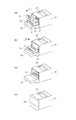
図3は装置本体10の斜視図であり、図3を用いてプロセスカートリッジ20の装着動作の概略を説明する。ユーザーがプロセスカートリッジ20の交換を行う際の操作性を向上するため、プロセスカートリッジ20を装置本体10に対してスライド可能なトレイ130に支持した状態で装置本体10から引き出す構成としている。プロセスカートリッジ20は画像形成されるにつれて、プロセスカートリッジ20内の現像ユニット220に収容されている現像剤100が消費される。そして現像剤100が消費された際にプロセスカートリッジ20の交換が必要になる。本実施形の画像形成装置におけるプロセスカートリッジ20の交換方法は、矢印F方向からトレイ130に着脱して交換する方式である。トレイ130はプロセスカートリッジ20を装着した状態で装置本体10に対して移動する移動部材(カートリッジ支持部材)である。
FIG. 3 is a perspective view of the apparatus
ユーザーがプロセスカートリッジ20を装置本体10に装着する際には、まず、図3(a)のようにユーザーは装置本体10のドア140を開け、トレイ130を引き出した状態で斜め上方からプロセスカートリッジ20をトレイ130に載せる。ドア140はトレイ130が挿入される装置本体10の開口を開閉する開閉部材である。
When the user attaches the
その後、図3(b)のように矢印Gの方向へプロセスカートリッジ20が載ったトレイ130を挿入する。図3(c)のようにトレイ130の装置本体10への挿入が完了すると、プロセスカートリッジ20の装置本体10への装着も同時に完了する。最後に、図3(d)のようにドア140を閉めることでプロセスカートリッジ20の装置本体10への装着動作が完了する。ユーザーは逆の動作でプロセスカートリッジ20を装置本体10から引出すことが可能である。
Thereafter, the
図3(a)、(b)は、トレイ130が装置本体10の外部の外部位置(第一の位置)にある状態である。トレイ130は外部位置にあるとき、プロセスカートリッジ20をトレイ130に対して着脱可能な状態にする。
3A and 3B show a state in which the
図3(c)、(d)は、トレイ130が装置本体10の内部の内部位置(第二の位置)にある状態である。トレイ130は内部位置にあるとき、プロセスカートリッジ20を装置本体10によって位置決めさせてプロセスカートリッジ20を画像形成が可能な状態にする。つまりトレイ130は内部位置においてプロセスカートリッジ20を画像形成が可能な位置に配置させる。
3C and 3D show a state in which the
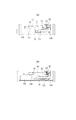
次にプロセスカートリッジ20が積載されたトレイ130およびプロセスカートリッジ20の装置本体10への挿入動作について、図4(a)〜(f)を参照して説明する。
Next, an operation of inserting the
図4(a)のようにプロセスカートリッジ20にはトレイ130に対しプロセスカートリッジ20の位置決めを行うための第一の被位置決め部22はプロセスカートリッジ20の側壁に一対設けられている。
As shown in FIG. 4A, the
またプロセスカートリッジ20には、装置本体10に設けられた本体ガイド150、200に対してそれぞれ位置決めを行うための第二の被位置決め部21、第三の被位置決め部23がプロセスカートリッジ20の側壁にそれぞれ一対ずつ設けられている。
Further, the
第二の被位置決め部21、第三の被位置決め部23は、プロセスカートリッジ20が装置本体に装着された際に(トレイ130が内部位置に移動した際に)、装置本体によって支持されるように構成された被支持部である。
The second positioned
本体ガイド150、200は、第二の被位置決め部21、第三の被位置決め部23を支持することで、カートリッジ20が装置本体10に装着されるのを案内する本体側カートリッジガイドである。
The main body guides 150 and 200 are main body side cartridge guides that guide the mounting of the
本体ガイド150、200は装置本体10に対して固定して設けられ、画像形成時のプロセスカートリッジ20を支持する。装置本体10内に挿入されたプロセスカートリッジ20を本体ガイド150、200にスムースに支持するために、本体ガイドにはそれぞれ第一の斜面151、第三の斜面201が設けられている。
The main body guides 150 and 200 are fixed to the apparatus
一方、トレイ13は、図4(b)の装置本体10から引き出された第一の位置(外部位置)から、図4(f)の装置本体10に挿入された第二の位置(内部位置)まで移動可能である。また、ドア140はユーザーによって開閉自在に装置本体10に設けられており、開くことによってトレイ130が装置本体10の外部に引き出されたとき、トレイ130を支持する支持部材となっている。
On the other hand, the tray 13 is inserted from the first position (external position) pulled out from the apparatus
<プロセスカートリッジの装着動作>
次に、プロセスカートリッジ20の装置本体10内部での装着動作について説明する。プロセスカートリッジ20を装置本体10に装着する際には、まず、図4(a)のようにドア140の上部で第一の位置まで引き出されたトレイ130にプロセスカートリッジ20を載せる。
<Process cartridge mounting operation>
Next, the mounting operation of the
このとき、図4(b)のように、プロセスカートリッジ20とトレイ130は第一の被位置決め部22とトレイ130のスリット135とが係合する。しかし、スリット135の幅が第一の被位置決め部22の幅よりも幅広であるため、プロセスカートリッジ20はトレイ130内でトレイ20の装置本体10への挿入の前後方向に移動可能である。
At this time, as shown in FIG. 4B, the
次にプロセスカートリッジ20が積載されたトレイ130を装置本体10に挿入していくと、図4(c)のようにプロセスカートリッジ20の第二の被位置決め部(突起部)21は装置本体10に設けられた本体ガイド150の第一の斜面151と接触する。このとき、図4(c)のようにトレイ130の第一の当接面131とプロセスカートリッジ20の第二の被位置決め部22には隙間がある。隙間がある場合には、プロセスカートリッジ20は第一の斜面151が抵抗となり、トレイ130の移動とは追従しない。
Next, when the
しかし、図4(d)のようにトレイ130の第一の当接面131とプロセスカートリッジ20の第一の被位置決め部(突起部)22が接触した状態でトレイ130を装置本体10の奥側へ押しこむ。すると、第一の当接面131によってプロセスカートリッジ20が押される。このとき第二の当接面132と第一の被位置決め部22の間には間隙が形成される(第二の当接面132と第一の被位置決め部22は接触していない)。
However, as shown in FIG. 4D, the
トレイ130の第一の当接面131は、プロセスカートリッジ20の第一の被位置決め部22に力を加えることで、前記プロセスカートリッジ20を装置本体10の内部に向けて移動させる第一力付与部である。第一被位置決め部22は、トレイ130(第一の当接面131)から力を受ける力受け部である。
The
第一の当接面131によってプロセスカートリッジ20が押されると、プロセスカートリッジ20に設けられた第二の被位置決め部21が第一の斜面151を移動し始める。同時に、プロセスカートリッジ20の第三の被位置決め部23も本体ガイド200の第三の斜面201を移動する。ここで第一の斜面151、第三の斜面201は第一の支持部材が外部位置から内部位置へ向かって移動する移動方向(図3(b)の矢印G参照)に向かって上方に傾斜した上方傾斜部である。
When the
そのため、プロセスカートリッジ20は、トレイ130が外部位置から内部位置に移動する過程で第一の斜面151、第三の201に沿って上方に移動する。プロセスカートリッジ20はトレイ130に対して持ち上げられる(トレイ130に対してプロセスカートリッジ20が相対的に上方に移動する)。その結果、プロセスカートリッジ20を支持する部材(プロセスカートリッジ20の重量を主に受ける部材)がトレイ130から本体ガイド150および本体ガイド200へと切り替わる。
Therefore, the
上方傾斜部は、プロセスカートリッジ20に複数備えられた被支持部(第二の被位置決め部21、第三被位置決め部23)に対応するように装置本体10に複数備えられているとよい。第一の斜面151は、移動部材が内部位置へ向かう移動方向(図3(b)の矢印G)において第三の斜面201よりも下流側(図4(d)における右側)に設けられた下流側の上方傾斜部(第一の上方傾斜部)である。一方、第三の斜面201は前記移動方向において、第一の斜面151よりも上流側(図4(d)における左側)に設けられた上流側の上方傾斜部(第二の上方傾斜部)である。さらにトレイ130を装置本体10奥側へ押し込むと、図4(f)のようにプロセスカートリッジ20の第二の被位置決め部(突起部)21が第二の斜面152に差し掛かる。すると、プロセスカートリッジ2の自重によりプロセスカートリッジ20の第二の被位置決め部21が第二の斜面152を滑り落ちる。そして、第二の被位置決め部21が装置本体10の奥側に設けられた本体ガイド150の突き当て面153と接触して、プロセスカートリッジ20は装置本体10内での位置が決まる。つまり、第二の斜面152と突き当て面153は、第二の被位置決め部21を位置決めするための本体側位置決め部である。つまり、突き当て面153と第二の斜面152によって形成されるV字状の溝がプロセスカートリッジ20の被支持部(第二の被位置決め部21)を支持する。このことで、プロセスカートリッジ20は画像形成が可能な位置に配置される(プロセスカートリッジ20が位置決めされる)。
A plurality of upward inclined portions may be provided in the apparatus
突き当て面153や第二の斜面152は被支持部を支持することで、本体側位置決め部(第一本体側被位置決め部)である。プロセスカートリッジ20の位置決めが本体側位置決め部(突き当て面153、第二傾斜部152)によって成されると、プロセスカートリッジ20に設けられた感光体ドラム40の位置決めも行われる。つまり感光体ドラム40も画像形成が可能な位置に配置される。つまり感光体ドラム40はスキャナユニット30(図1参照)からレーザ光を受けて潜像が形成される位置にある。
The
なお、第二の斜面152によって、プロセスカートリッジ20(第二の被位置決め部21)は下方に移動する(下降する)ことになる。しかしその下降量は第一の斜面151によってプロセスカートリッジ20(第二の被位置決め部21)が上昇した上昇量よりは小さい。そのためプロセスカートリッジ20は装置本体10に位置決めされた状態で、少なくとも一部がトレイ130に対して持ち上がった状態で保持されている(図4(f)参照)。
The process cartridge 20 (second positioned portion 21) is moved downward (lowered) by the second
また、トレイ130は先端部133が装置本体10の奥側に設けられた突き当て部11と接触して、装置本体10内での位置が決まる。トレイ130は内部位置(第二の位置)にある状態である。このとき、プロセスカートリッジ20は上述のように自重によって第二の斜面を滑り落ちるため、プロセスカートリッジ20の力受け部(第一の被位置決め部22)とトレイ130の押込み部(第一の当接面131)は離間している。
Further, the position of the
したがってプロセスカートリッジ20は本体ガイド150、200のみで支持され、他部材による接触や干渉がなく、安定した位置において画像形成が可能となる。
Therefore, the
本体ガイド200は第三の被位置決め部23を支持することでプロセスカートリッジ20が第二の被位置決め部21を中心に回転することを抑えている。つまり本体ガイド200もプロセスカートリッジ20の被支持部(第三の被位置決め部23)を支持することでプロセスカートリッジを画像形成が可能な状態(位置)に位置決めしている。本体ガイド200はプロセスカートリッジ20の装着をガイドする本体側カートリッジガイドであると同時に、プロセスカートリッジの位置決めを行う本体側位置決め部(第二本体側位置決め部)を兼ねている。
The
本実施形態では、トレイ130をユーザーが装置本体10の内部に挿入することによって、プロセスカートリッジ20を装置本体10(本体ガイド150、200)によって支持、位置決めさせることができた。
In the present embodiment, when the user inserts the
つまり従来のようにドア10の開閉に連動させてトレイ130をプロセスカートリッジ20から退避(離す)必要はない。したがってドア10の開閉とトレイ130を連動させる連動機構を装置本体10に設ける必要はなく装置本体10を小型化、低コスト化できる。
That is, there is no need to retract (separate) the
すなわち本実施形態ではトレイ130が装置本体10に挿入された時点で、ドア10が開いた状態(図3(c))であってもカートリッジ20は装置本体10(本体ガイド150、200)によって支持、位置決めされる。
That is, in this embodiment, when the
なおプロセスカートリッジの被支持部である第二の被位置決め部21、第三の被位置決め部23のうち、第二の被位置決め部21は、トレイ130が内部位置に向けて移動する移動方向において下流側(図4(f)の右側)に位置する。つまり第二の被位置決め部21は下流側の被支持部(第一被支持部)である。一方、第三の被位置決め部23は、前記移動方向において第二の被位置決め部21よりも上流側(左側)に位置する上流側の被支持部(第二被支持部)である。
Of the second positioned
<プロセスカートリッジの引出し動作>
次に、プロセスカートリッジ20の装置本体10内部からの引出し動作について説明する。
<Drawing operation of process cartridge>
Next, the drawing operation of the
基本動作は装着時の逆動作であるため、装着時と同様に図4を用いて説明する。図4(f)のように装着された状態のプロセスカートリッジ20はトレイ130から離間しているため、トレイ130の引き始めにはプロセスカートリッジ20は移動しない。しかし、トレイ130の第二の当接部132がプロセスカートリッジ20の第一の被位置決め部22に当接した状態でトレイ130を引き出すと、プロセスカートリッジ20はトレイ130の移動に追従する。このとき、第一の当接部131と第一の被位置決め部22の間には間隙が設けられている(第一の当接部131と第一の被位置決め部22は離れている)。
Since the basic operation is the reverse operation at the time of wearing, it will be described with reference to FIG. Since the
前記第二の当接部132は、トレイ130が外部位置(第1の位置)に向けて移動する際に、プロセスカートリッジの力受け部(第一の被位置決め部22)力を加えることでプロセスカートリッジを装置本体10の外部に移動させる第二力付与部である。
The
プロセスカートリッジ20が第二の当接部132から押されることで、第二の被位置決め部21が本体ガイド150の第二の斜面152を登り始める。このとき、プロセスカートリッジ20は本体ガイド150、200に支持される。さらにトレイ130を引出すと、図4(d)のようにプロセスカートリッジ20の第一の被位置決め部22、及び、第三の被位置決め部23が本体ガイド150の第一の斜面151、及び、本体ガイド200の第三の斜面201をそれぞれ滑り下りる。プロセスカートリッジ20を支持する支持部は装置本体10(本体ガイド150、200)からトレイ130に切り替わる。
When the
トレイ130に支持されたプロセスカートリッジ20はトレイ130とともに図4(b)のように装置本体10から着脱可能な第一の位置(外部位置)まで引き出され、トレイ130から着脱可能な状態となる。なお、本実施形態においてトレイ20の挿抜軌跡は略水平となっている。
The
次に、図5を参照にして、本体ガイド150の第一の斜面151と第二の斜面152についての説明を補足する。
Next, with reference to FIG. 5, the description about the
第一の斜面151は、トレイ130が第一の位置(外部位置)から第二の位置(内部位置)に移動する移動方向(図3の矢印G参照)に向かって上方に傾斜する上方傾斜部である。プロセスカートリッジ20を装置本体10に装着する時には、上述のようにユーザーがトレイ130を挿入し、第一の当接部131がプロセスカートリッジ2の第一の被位置決め部22を押すことで、プロセスカートリッジ20は第一の斜面151を登る。したがって、第一の斜面151と水平面とのなす角度αが小さいほど、プロセスカートリッジ20を挿入する際の抵抗が小さくなり、ユーザーの操作力は小さくなる。
The first
一方、プロセスカートリッジ20の第二の被位置決め部21が第二の斜面152に差し掛かると、プロセスカートリッジ20は第二の斜面152を滑り落ちる。つまり、第二の斜面152と水平面とのなす角度βが大きいほど、トレイ130が第二の位置においてプロセスカートリッジ20は装置本体10に安定して位置決めされる。
On the other hand, when the second positioned
したがって、
α(第一の斜面と水平面のなす角)<β(第二の斜面と水平面のなす角)
とした。このような関係が成立することで、プロセスカートリッジ20は挿入時には装置本体10に入れ易く、画像形成時には装置本体10に対する位置を安定させることができる。
Therefore,
α (the angle between the first slope and the horizontal plane) <β (the angle between the second slope and the horizontal plane)
It was. By establishing such a relationship, the
第二の斜面152は、トレイ130が第一の位置(外部位置)から第二の位置(内部位置)に移動する移動方向に向かって下方に傾斜する下方傾斜部である。第二の斜面152は第二の被位置決め部21(被支持部)が第一の斜面151(上方傾斜部)を通過した後、突き当て面153(本体側位置決め部)に支持される前に、第二の被位置決め部21を突き当て面131に向けて案内するものある。
The second
なお、現像ユニット220とクリーニングユニット230が一体となったいわゆる一体型のプロセスカートリッジを用いた例を説明したが、本発明は一体型のプロセスカートリッジを用いた場合に限定されるものではない。たとえば現像ユニット220とクリーニングユニット230がそれぞれ個別にカートリッジ化されて、装置本体に装着される構成であってもよい。また、装置本体に対して1つのプロセスカートリッジを装着した例を説明したが、装置本体に対して1つのプロセスカートリッジを用いた場合に本発明を限定するものではない。
Although an example using a so-called integrated process cartridge in which the developing
《第二の実施形態》
次に、本発明にかかる第二の実施形態について、図6(a)(b)を参照して説明する。
<< Second Embodiment >>
Next, a second embodiment according to the present invention will be described with reference to FIGS.
なお、本実施形態での装置の基本構成は前述した第一の実施形態と同一であるため、重複する部分については説明を省略し、ここでは本実施形態の特徴となる構成について説明する。また、前述した第一の実施形態と同一機能を有する部材は同一符号とする。 Since the basic configuration of the apparatus in the present embodiment is the same as that of the first embodiment described above, the description of the overlapping parts is omitted, and the configuration that is a feature of the present embodiment will be described here. Members having the same functions as those of the first embodiment described above are denoted by the same reference numerals.
本実施形態では、第一の実施形態と比べると、本体ガイド150に図5(b)のような第二の斜面152を設けていない点で異なる。つまり本実施形態では第一の実施形態と異なり、プロセスカートリッジ20の上部からバネ170を用いてプロセスカートリッジ20の第二の被位置決め部(突起部)21を本体ガイド150の突き当て面153と当接するように付勢している。バネ170は、プロセスカートリッジ20に設けられた被支持部(第二の被位置決め部21)を本体側位置決め部(突き当て面153)に向けて付勢する付勢部である。
This embodiment is different from the first embodiment in that the
バネ170によって第二の被位置決め部21が付勢されることによって、第一の実施形態に対して、プロセスカートリッジ20の重量に依存せず、プロセスカートリッジ20の位置を装置本体10に対して安定させることが可能となる。また、第一の実施形態においても、第二の実施形態と同様の付勢部(バネ170)を追加することで、より確実に位置の固定を行うことが可能である。本実施形態においては、バネ170をプロセスカートリッジ20の上部に配置したが、バネ170をプロセスカートリッジ20の下部に配置することも可能である。
By urging the second positioned
《第三の実施形態》
次に、第三の実施形態について、図7を参照して説明する。
<< Third embodiment >>
Next, a third embodiment will be described with reference to FIG.
なお、本実施形態での装置の基本構成は前述した第一の実施形態と同一であるため、重複する部分については説明を省略し、ここでは本実施形態の特徴となる構成について説明する。また、前述した第一の実施形態と同一機能を有する部材は同一符号とする。 Since the basic configuration of the apparatus in the present embodiment is the same as that of the first embodiment described above, the description of the overlapping parts is omitted, and the configuration that is a feature of the present embodiment will be described here. Members having the same functions as those of the first embodiment described above are denoted by the same reference numerals.
図7は本実施形態における画像形成装置の断面図である。 FIG. 7 is a sectional view of the image forming apparatus according to this embodiment.
第三の実施形態では、第一の実施形態とは比較すると、プロセスカートリッジ20が装置本体10内部で移動する際に斜面部にガイドされて鉛直上方向に移動することなく、略水平に移動する。一方、トレイ130が装置本体10内部で移動する際に鉛直方向に上下動することでプロセスカートリッジ20とトレイ130への支持、あるいは離間を実現している点で異なる。
In the third embodiment, as compared with the first embodiment, the
具体的な構成について以下に説明する。図7(a)のようにトレイ13の底部には凸部134が設けられ、装置本体10には凸部134に対応するように凹部12が設けられている。
A specific configuration will be described below. As shown in FIG. 7A, a
図7(a)においてプロセスカートリッジ20はトレイ130に支持され、トレイ130の移動に追従する。図7(b)のようにトレイ130を装置本体10に挿入していくと、トレイ130の凸部134が装置本体の凹部12に沿って移動し、トレイ130は下方に移動する。凸部134が凹部12にはまると、トレイ130はプロセスカートリッジ20に対して下方に離れることから、プロセスカートリッジ20を支持する支持部はトレイ130から本体ガイド150、及び、200に切り替わる。
In FIG. 7A, the
本実施形態において凹部12は、カートリッジトレイ130が内部位置(第二の位置)に向けて移動するのを案内するガイド(本体側移動部材ガイド)の一部である。凹部12(本体側移動部材ガイド)はトレイ130が内部位置に向けて移動する過程でトレイ130を下降させる。これにより、凹部12(本体側移動部材ガイド)はプロセスカートリッジ20をトレイ130に支持された状態から装置本体10(本体ガイド150、200)に支持された状態に移す働きをする。
In the present embodiment, the
さらにトレイ130を押しこむとトレイ130の先端部133と装置本体10の突き当て部11が接触し、装置本体10に対するトレイ130の装着が完了する。このとき、プロセスカートリッジ20はバネ170によって本体ガイド150と当接するように付勢され、プロセスカートリッジ20とトレイ130は離間されている状態である。第三の実施形態では、プロセスカートリッジ20が挿抜軌跡において本体に設けられた支持部材の斜面部を登る必要がないため、プロセスカートリッジ20の重量が重い場合には、第一の実施形態に比べてユーザーの操作力を軽減することが可能となる。
When the
10 装置本体
20 プロセスカートリッジ
21 第二の被位置決め部
23 第三の被位置決め部
130 トレイ
150 本体ガイド
151 第一の斜面
152 第二の斜面
153 本体ガイドの突き当て面
200 本体ガイド
201 第三の斜面
F トレイ挿入方向
G トレイ引出し方向
DESCRIPTION OF
Claims (16)
被支持部及び現像剤像を担持する感光ドラムを備えたカートリッジを内部に収容可能な装置本体と、
前記装置本体に設けられて、前記被支持部を支持することで前記カートリッジを画像形成が可能な位置に位置決めする本体側位置決め部と、
前記カートリッジを装着した状態で前記装置本体に対して前記感光ドラムの軸と交差する方向に移動することで、前記装置本体の外部にあって前記カートリッジを着脱させる外部位置と、前記装置本体の内部にあって前記カートリッジを前記本体側位置決め部に接触して位置決めさせる内部位置と、を取り得る移動部材と、
前記装置本体に設けられて、前記移動部材が前記外部位置から前記内部位置へ移動する移動方向に向かって上方に傾斜した上方傾斜部と、
前記移動部材に設けられ、前記カートリッジの力受け部に力を加え、前記カートリッジを前記装置本体の内部に移動させる第1力付与部と、を有し、
前記上方傾斜部は、前記移動部材が前記外部位置から前記内部位置に向けて移動する過程で前記カートリッジの被支持部と接触することにより、前記カートリッジを前記移動部材に対して上方に移動させ、
前記移動部材が前記外部位置から前記内部位置に向けて移動する過程で、前記カートリッジは前記上方傾斜部及び前記第1力付与部に接触したままの状態で前記移動方向に移動し、
前記移動部材が前記内部位置にある際に、前記第1力付与部と前記力受け部は離れていることを特徴とする画像形成装置。 In an image forming apparatus for forming an image on a recording medium,
An apparatus main body capable of accommodating therein a cartridge including a photosensitive drum carrying a supported portion and a developer image ;
A main body side positioning portion that is provided in the apparatus main body and positions the cartridge at a position where image formation is possible by supporting the supported portion;
An external position outside the apparatus main body where the cartridge is attached and detached by moving in a direction intersecting the axis of the photosensitive drum with respect to the apparatus main body in a state where the cartridge is mounted, and an inside of the apparatus main body An internal position for positioning the cartridge in contact with the main body side positioning portion;
An upper inclined portion provided in the apparatus main body and inclined upward in a moving direction in which the moving member moves from the external position to the internal position;
A first force applying portion that is provided on the moving member, applies a force to the force receiving portion of the cartridge, and moves the cartridge into the apparatus main body;
The upper inclined portion moves the cartridge upward with respect to the moving member by contacting the supported portion of the cartridge in a process in which the moving member moves from the external position toward the internal position.
In the process in which the moving member moves from the external position toward the internal position, the cartridge moves in the moving direction while being in contact with the upper inclined portion and the first force applying portion,
The image forming apparatus according to claim 1 , wherein the first force applying unit and the force receiving unit are separated when the moving member is in the internal position.
前記上方傾斜部は前記本体側カートリッジガイドに設けられることを特徴とする請求項1に記載の画像形成装置。 The apparatus main body includes a main body side cartridge guide for guiding the supported portion to the main body side positioning portion,
The image forming apparatus according to claim 1, wherein the upper inclined portion is provided in the main body side cartridge guide.
前記被支持部が前記上方傾斜部を通過した後かつ前記本体側位置決め部に位置を決められる前に、前記下方傾斜部は前記被支持部と接触することで前記被支持部を前記本体側位置決め部に向けて案内することを特徴とする請求項1または2に記載の画像形成装置。 The apparatus main body has a downward inclined portion inclined downward in the moving direction,
After the supported portion passes the upper inclined portion and before the position is determined by the main body side positioning portion, the lower inclined portion comes into contact with the supported portion to position the supported portion on the main body side. The image forming apparatus according to claim 1, wherein the image forming apparatus guides toward a part.
前記移動部材が前記外部位置から前記内部位置へ移動することで、前記開閉部材が開いた状態のまま前記カートリッジは前記本体側位置決め部に位置決めされることを特徴とする請求項1乃至5のいずれか1項に記載の画像形成装置。 The apparatus body includes an opening / closing member that opens and closes an opening into which the moving member is inserted,
By the moving member is moved to the inner position from the outside position, the cartridge remain the closing member is opened any of claims 1 to 5, characterized in that it is positioned on the main body side positioning portion The image forming apparatus according to claim 1.
前記装置本体は前記第一被支持部と前記第二被支持部に対応させて、前記上方傾斜部と前記本体側位置決め部をそれぞれ複数備えることを特徴とする請求項1乃至6のいずれか1項に記載の画像形成装置。 The cartridge includes a first supported portion as the supported portion, and a second supported portion located upstream of the first supported portion in the moving direction with respect to the first supported portion,
The apparatus main body so as to correspond to the second supported portion and the first supported portion, any one of claims 1 to 6, characterized in that it comprises a plurality and said upper inclined portion the main body side positioning portion, respectively The image forming apparatus described in the item.
被支持部及び現像剤を担持して潜像を現像する現像ローラを備えたカートリッジを内部に収容可能な装置本体と、An apparatus main body capable of accommodating therein a cartridge including a developing roller for carrying a supported portion and a developer and developing a latent image;
前記装置本体に設けられて、前記被支持部を支持することで前記カートリッジを画像形成が可能な位置に位置決めする本体側位置決め部と、A main body side positioning portion that is provided in the apparatus main body and positions the cartridge at a position where image formation is possible by supporting the supported portion;
前記カートリッジを装着した状態で前記装置本体に対して前記現像ローラの軸と交差する方向に移動することで、前記装置本体の外部にあって前記カートリッジを着脱させる外部位置と、前記装置本体の内部にあって前記カートリッジを前記本体側位置決め部に接触して位置決めさせる内部位置と、を取り得る移動部材と、An external position outside the apparatus main body where the cartridge is attached and detached by moving in a direction crossing the axis of the developing roller with respect to the apparatus main body in a state where the cartridge is mounted, and an inside of the apparatus main body An internal position for positioning the cartridge in contact with the main body side positioning portion;
前記装置本体に設けられて、前記移動部材が前記外部位置から前記内部位置へ移動する移動方向に向かって上方に傾斜した上方傾斜部と、An upper inclined portion provided in the apparatus main body and inclined upward in a moving direction in which the moving member moves from the external position to the internal position;
前記移動部材に設けられ、前記カートリッジの力受け部に力を加え、前記カートリッジを前記装置本体の内部に移動させる第1力付与部と、を有し、A first force applying portion that is provided on the moving member, applies a force to the force receiving portion of the cartridge, and moves the cartridge into the apparatus main body;
前記上方傾斜部は、前記移動部材が前記外部位置から前記内部位置に向けて移動する過程で前記カートリッジの被支持部と接触することにより、前記カートリッジを前記移動部材に対して上方に移動させ、The upper inclined portion moves the cartridge upward with respect to the moving member by contacting the supported portion of the cartridge in a process in which the moving member moves from the external position toward the internal position.
前記移動部材が前記外部位置から前記内部位置に向けて移動する過程で、前記カートリッジは前記上方傾斜部及び前記第1力付与部に接触したままの状態で前記移動方向に移動し、In the process in which the moving member moves from the external position toward the internal position, the cartridge moves in the moving direction while being in contact with the upper inclined portion and the first force applying portion,
前記移動部材が前記内部位置にある際に、前記第1力付与部と前記力受け部は離れていることを特徴とする画像形成装置。The image forming apparatus according to claim 1, wherein the first force applying unit and the force receiving unit are separated when the moving member is in the internal position.
前記上方傾斜部は前記本体側カートリッジガイドに設けられることを特徴とする請求項8に記載の画像形成装置。The image forming apparatus according to claim 8, wherein the upper inclined portion is provided in the main body side cartridge guide.
前記被支持部が前記上方傾斜部を通過した後かつ前記本体側位置決め部に位置を決められる前に、前記下方傾斜部は前記被支持部と接触することで前記被支持部を前記本体側位置決め部に向けて案内することを特徴とする請求項8または9に記載の画像形成装置。After the supported portion passes the upper inclined portion and before the position is determined by the main body side positioning portion, the lower inclined portion comes into contact with the supported portion to position the supported portion on the main body side. The image forming apparatus according to claim 8, wherein the image forming apparatus guides toward the portion.
前記移動部材が前記外部位置から前記内部位置へ移動することで、前記開閉部材が開いた状態のまま前記カートリッジは前記本体側位置決め部に位置決めされることを特徴とする請求項8乃至12のいずれか1項に記載の画像形成装置。13. The cartridge according to claim 8, wherein the moving member moves from the external position to the internal position, whereby the cartridge is positioned by the main body side positioning portion while the opening / closing member is open. The image forming apparatus according to claim 1.
前記装置本体は前記第一被支持部と前記第二被支持部に対応させて、前記上方傾斜部と前記本体側位置決め部をそれぞれ複数備えることを特徴とする請求項8乃至13のいずれか1項に記載の画像形成装置。14. The apparatus according to claim 8, wherein the apparatus main body includes a plurality of the upper inclined portions and the main body side positioning portions in correspondence with the first supported portion and the second supported portion, respectively. The image forming apparatus described in the item.
Priority Applications (6)
| Application Number | Priority Date | Filing Date | Title |
|---|---|---|---|
| JP2014242594A JP6463100B2 (en) | 2014-11-28 | 2014-11-28 | Image forming apparatus |
| CN201510793517.5A CN105652628B (en) | 2014-11-28 | 2015-11-18 | Image forming apparatus |
| US14/948,759 US9804559B2 (en) | 2014-11-28 | 2015-11-23 | Image forming apparatus including a moving member configured to move a cartridge |
| EP15196364.2A EP3026502B1 (en) | 2014-11-28 | 2015-11-25 | Image forming apparatus |
| US15/706,539 US10025269B2 (en) | 2014-11-28 | 2017-09-15 | Image forming apparatus having member for positioning cartridge |
| US16/011,338 US10401787B2 (en) | 2014-11-28 | 2018-06-18 | Image forming apparatus having member for positioning cartridge |
Applications Claiming Priority (1)
| Application Number | Priority Date | Filing Date | Title |
|---|---|---|---|
| JP2014242594A JP6463100B2 (en) | 2014-11-28 | 2014-11-28 | Image forming apparatus |
Related Child Applications (1)
| Application Number | Title | Priority Date | Filing Date |
|---|---|---|---|
| JP2018245430A Division JP6783846B2 (en) | 2018-12-27 | 2018-12-27 | Image forming device |
Publications (3)
| Publication Number | Publication Date |
|---|---|
| JP2016102987A JP2016102987A (en) | 2016-06-02 |
| JP2016102987A5 JP2016102987A5 (en) | 2018-01-18 |
| JP6463100B2 true JP6463100B2 (en) | 2019-01-30 |
Family
ID=54705426
Family Applications (1)
| Application Number | Title | Priority Date | Filing Date |
|---|---|---|---|
| JP2014242594A Active JP6463100B2 (en) | 2014-11-28 | 2014-11-28 | Image forming apparatus |
Country Status (4)
| Country | Link |
|---|---|
| US (3) | US9804559B2 (en) |
| EP (1) | EP3026502B1 (en) |
| JP (1) | JP6463100B2 (en) |
| CN (1) | CN105652628B (en) |
Families Citing this family (11)
| Publication number | Priority date | Publication date | Assignee | Title |
|---|---|---|---|---|
| JP6991702B2 (en) * | 2016-09-21 | 2022-01-12 | キヤノン株式会社 | Image forming device |
| JP7005250B2 (en) * | 2017-09-21 | 2022-01-21 | キヤノン株式会社 | Developer replenishment container |
| JP7009132B2 (en) | 2017-09-21 | 2022-01-25 | キヤノン株式会社 | Developer replenishment container and developer replenishment system |
| JP7000091B2 (en) * | 2017-09-21 | 2022-01-19 | キヤノン株式会社 | Developer replenishment container and developer replenishment system |
| JP7102940B2 (en) | 2018-05-24 | 2022-07-20 | ブラザー工業株式会社 | Image forming device |
| JP2020046513A (en) * | 2018-09-18 | 2020-03-26 | ブラザー工業株式会社 | Image forming apparatus |
| JP7379953B2 (en) | 2019-09-02 | 2023-11-15 | ブラザー工業株式会社 | Image forming device |
| JP7379954B2 (en) | 2019-09-02 | 2023-11-15 | ブラザー工業株式会社 | Image forming device |
| JP7306169B2 (en) * | 2019-09-02 | 2023-07-11 | ブラザー工業株式会社 | image forming device |
| JP2021152596A (en) | 2020-03-24 | 2021-09-30 | ブラザー工業株式会社 | Image forming apparatus |
| US20230259064A1 (en) * | 2022-02-15 | 2023-08-17 | Ricoh Company, Ltd. | Image forming apparatus |
Family Cites Families (18)
| Publication number | Priority date | Publication date | Assignee | Title |
|---|---|---|---|---|
| JP2861721B2 (en) | 1993-04-14 | 1999-02-24 | 富士ゼロックス株式会社 | Image forming device |
| JP4241819B2 (en) | 2006-01-11 | 2009-03-18 | キヤノン株式会社 | Color electrophotographic image forming apparatus |
| JP4464435B2 (en) * | 2006-12-11 | 2010-05-19 | キヤノン株式会社 | Process cartridge and electrophotographic image forming apparatus |
| JP4975561B2 (en) | 2007-08-31 | 2012-07-11 | 株式会社リコー | Conveying device, image forming apparatus |
| JP4556992B2 (en) * | 2007-12-04 | 2010-10-06 | ブラザー工業株式会社 | Image forming apparatus |
| US8311437B2 (en) * | 2007-12-04 | 2012-11-13 | Brother Kogyo Kabushiki Kaisha | Image forming apparatus with detachable cartridge |
| JP2010008742A (en) * | 2008-06-27 | 2010-01-14 | Oki Data Corp | Image forming apparatus |
| JP4600535B2 (en) * | 2008-06-27 | 2010-12-15 | ブラザー工業株式会社 | Image forming apparatus |
| JP4508273B2 (en) * | 2008-06-30 | 2010-07-21 | ブラザー工業株式会社 | Image forming apparatus |
| JP4710972B2 (en) * | 2008-12-26 | 2011-06-29 | ブラザー工業株式会社 | Image forming apparatus |
| JP4948585B2 (en) * | 2009-10-30 | 2012-06-06 | キヤノン株式会社 | Image forming apparatus |
| JP5839823B2 (en) * | 2011-04-15 | 2016-01-06 | キヤノン株式会社 | Image forming apparatus |
| US8768202B2 (en) | 2010-06-02 | 2014-07-01 | Canon Kabushiki Kaisha | Image forming apparatus |
| JP5338833B2 (en) * | 2011-03-23 | 2013-11-13 | ブラザー工業株式会社 | Image forming apparatus |
| JP5838611B2 (en) * | 2011-06-27 | 2016-01-06 | ブラザー工業株式会社 | Image forming apparatus |
| JP5768530B2 (en) * | 2011-06-27 | 2015-08-26 | ブラザー工業株式会社 | Image forming apparatus |
| KR20130056390A (en) * | 2011-11-22 | 2013-05-30 | 삼성전자주식회사 | Image forming apparatus |
| JP6278665B2 (en) * | 2013-11-20 | 2018-02-14 | キヤノン株式会社 | Image forming apparatus |
-
2014
- 2014-11-28 JP JP2014242594A patent/JP6463100B2/en active Active
-
2015
- 2015-11-18 CN CN201510793517.5A patent/CN105652628B/en active Active
- 2015-11-23 US US14/948,759 patent/US9804559B2/en active Active
- 2015-11-25 EP EP15196364.2A patent/EP3026502B1/en active Active
-
2017
- 2017-09-15 US US15/706,539 patent/US10025269B2/en active Active
-
2018
- 2018-06-18 US US16/011,338 patent/US10401787B2/en active Active
Also Published As
| Publication number | Publication date |
|---|---|
| JP2016102987A (en) | 2016-06-02 |
| CN105652628A (en) | 2016-06-08 |
| US20180004154A1 (en) | 2018-01-04 |
| US20180299824A1 (en) | 2018-10-18 |
| US10025269B2 (en) | 2018-07-17 |
| CN105652628B (en) | 2019-10-29 |
| US20160154375A1 (en) | 2016-06-02 |
| US9804559B2 (en) | 2017-10-31 |
| EP3026502A1 (en) | 2016-06-01 |
| US10401787B2 (en) | 2019-09-03 |
| EP3026502B1 (en) | 2018-04-04 |
Similar Documents
| Publication | Publication Date | Title |
|---|---|---|
| JP6463100B2 (en) | Image forming apparatus | |
| US11567431B2 (en) | Process unit | |
| US9829857B2 (en) | Image forming apparatus including an erroneous attaching prevention unit | |
| KR101772967B1 (en) | Developing unit and image forming apparatus using the same | |
| JP2006276176A (en) | Contact evading mechanism and image forming apparatus using same | |
| JP6600986B2 (en) | Image forming apparatus | |
| JP2006267620A (en) | Image forming apparatus, drawer cartridge, roller unit, and recorded medium storing cartridge | |
| KR101451707B1 (en) | Developing device and image forming apparatus | |
| JP2006056065A (en) | Image forming apparatus | |
| US9507309B2 (en) | Image forming apparatus | |
| JP6783846B2 (en) | Image forming device | |
| JP7187976B2 (en) | image forming device | |
| JP2014235290A (en) | Image forming apparatus | |
| WO2020183742A1 (en) | Image forming apparatus | |
| JP5949033B2 (en) | Image forming apparatus | |
| JP2023139300A (en) | Image forming apparatus | |
| JP2020144357A (en) | Image forming device | |
| JP6418001B2 (en) | Image forming apparatus | |
| JP2021123471A (en) | Image forming device | |
| JP2011154062A (en) | Image forming apparatus | |
| JP2013050581A (en) | Image forming device | |
| JP2012008452A (en) | Image forming device |
Legal Events
| Date | Code | Title | Description |
|---|---|---|---|
| A521 | Request for written amendment filed |
Free format text: JAPANESE INTERMEDIATE CODE: A523 Effective date: 20171128 |
|
| A621 | Written request for application examination |
Free format text: JAPANESE INTERMEDIATE CODE: A621 Effective date: 20171128 |
|
| A977 | Report on retrieval |
Free format text: JAPANESE INTERMEDIATE CODE: A971007 Effective date: 20180723 |
|
| A131 | Notification of reasons for refusal |
Free format text: JAPANESE INTERMEDIATE CODE: A131 Effective date: 20180731 |
|
| A521 | Request for written amendment filed |
Free format text: JAPANESE INTERMEDIATE CODE: A523 Effective date: 20180926 |
|
| TRDD | Decision of grant or rejection written | ||
| A01 | Written decision to grant a patent or to grant a registration (utility model) |
Free format text: JAPANESE INTERMEDIATE CODE: A01 Effective date: 20181204 |
|
| A61 | First payment of annual fees (during grant procedure) |
Free format text: JAPANESE INTERMEDIATE CODE: A61 Effective date: 20181228 |
|
| R151 | Written notification of patent or utility model registration |
Ref document number: 6463100 Country of ref document: JP Free format text: JAPANESE INTERMEDIATE CODE: R151 |