EP4273590A1 - Device for determination of specific activity of radiocarbon (14c) - Google Patents
Device for determination of specific activity of radiocarbon (14c) Download PDFInfo
- Publication number
- EP4273590A1 EP4273590A1 EP23163010.4A EP23163010A EP4273590A1 EP 4273590 A1 EP4273590 A1 EP 4273590A1 EP 23163010 A EP23163010 A EP 23163010A EP 4273590 A1 EP4273590 A1 EP 4273590A1
- Authority
- EP
- European Patent Office
- Prior art keywords
- catcher
- outlet
- detectors
- linked
- chamber
- Prior art date
- Legal status (The legal status is an assumption and is not a legal conclusion. Google has not performed a legal analysis and makes no representation as to the accuracy of the status listed.)
- Granted
Links
Images
Classifications
-
- G—PHYSICS
- G01—MEASURING; TESTING
- G01T—MEASUREMENT OF NUCLEAR OR X-RADIATION
- G01T7/00—Details of radiation-measuring instruments
- G01T7/02—Collecting means for receiving or storing samples to be investigated and possibly directly transporting the samples to the measuring arrangement; particularly for investigating radioactive fluids
Definitions
- the present invention relates to the methods and devices used for the detection of activity of radioactive samples and thus it can be used in the field of evaluation of radioactive waste.
- a possibility of determining specific activity of radioactive samples of different origin also provides a possibility to employ new conceptual methods of radioactivity evaluation in the field of biology, medicine, and material science.
- the nearest known apparatus is described in 2018 (https://doi.org/10.1371/journal.pone.0191677 ) and in 2020 (https://doi.org/10.15388/vu.thesis.75 ).
- the known apparatus consists of elemental analyzer (which consists of autosampler, oxidation and reduction columns, water trap, chromatographic column, thermal conductivity detector (TCD) and ⁇ detection unit which consists of two detectors, two preamplifiers, two single-channel analyzers, a PC and a gas catcher.
- TCD thermal conductivity detector
- ⁇ detection unit which consists of two detectors, two preamplifiers, two single-channel analyzers, a PC and a gas catcher.
- the two detectors are not connected together and correspondingly, the data is recorded from both detectors independently. After performing combustion of samples, the solution obtained from the catchers is mixed with liquid scintillator.
- the present invention seeks to improve the detection limit of 14 C specific activity measurement by suppressing the influence of radiation background, it also seeks to improve the accuracy of specific activity measurement by employing a freely selectable duration of CO 2 exposure in the detection chamber, it also seeks to simplify and optimize the unit of the CO 2 amount detection thus making the apparatus more practical and cost-efficient and thus broadening the field of apparatus' applications.
- the proposed device for determination of specific activity of radiocarbon ( 14 C) comprising a combustor which outlet is linked to a water vapor and aerosol particle catcher, a chemical CO 2 catcher, a carrier gas balloon which supplies the carrier gas into the device system, and a ⁇ - particle detection system, wherein -the device is provided with:
- the optic CO 2 amount analyzer (4) is configured to measure the light absorption in the gas stream, said light absorption being dependent on CO 2 concentration data are time integrated, where the value of the integral is proportional to an amount of CO 2 that has passed through the device system over the integrated time period.
- the geometry of the chamber of ⁇ -particle detection is cylindrical and the detectors are disc-shaped, wherein the distance h between detectors and is about 2,5 times smaller than their diameter d.
- a System for the determination of specific activity of radiocarbon 14 C comprising any device according to any one of claims 1 - 3.
- the proposed device allows to improve the detection limit of 14 C activity by suppressing the signals from the background radioactivity, therefore, as long as the background signal is lower and detection limit is better, so the measurement range is broader and measurement precision is better. This may be particularly useful for the applications in the fields of biology, medicine and material science, for example in biological samples that make use of 14 C glucose as a radioactive marker.
- the desirable statistical accuracy of activity measurements is achieved by selecting the duration of activity detection, independently from the parameters of the carrier gas flow.
- Optical CO 2 amount analyzer reduces the cost of the device and simplifies its operation and maintenance.
- a device for determination of specific activity of radiocarbon comprises: a combustor 1, a water vapor and aerosol particle catcher 2, a zeolitic catcher 3, an optic CO 2 amount analyzer 4, a cryogenic CO 2 catcher 5, a chamber 6 of ⁇ -particles detection, a vacuum pump 7, a chemical CO 2 catcher 8, two single-channel analyzers of electric pulse amplitude 9' and 9", an anti-coincidence circuit 10, an electric pulse counter 11, a digital controller 12 and carrier gas balloon 13.
- the Chamber of ⁇ -detection 6 comprises two semiconductor detectors in the shape of disks 14' and 14", which outputs correspondingly through the two single-channel pulse amplitude analyzers 9' and 9" are connected to the anti-coincidence circuit 10.
- the anti-coincidence circuit 10 is configured to produce an output pulse when it receives a pulse from any one of the semiconductor detectors 14' or 14" through the respective pulse amplitude analyzers 9' or 9" and to suppress the output pulse when the anti-coincidence circuit 10 receives the pulses from both detectors 14' and 14" through the pulse amplitude analyzers 9' and 9", simultaneously.
- Radioactive graphite is placed into the combustor 1 which is maintained at the temperature of about +1000 °C in the air environment.
- the sample thus is converted into CO 2 (gas), NO x oxides (gases) and H 2 O (gas). These compounds are further transferred into the system with carrier gas (N 2 , Ar or He) 13 which are supplied into the system through the controlled valves A and D.
- carrier gas N 2 , Ar or He
- the compounds pass through the water vapor and aerosol particle catcher 2.
- the catcher removes water vapor and aerosol particles while it transmits the CO 2 gas.
- the gas mixture that contains CO 2 , Rn and carrier gas passes from the water vapor and aerosol particle catcher 2 into the zeolitic catcher 3 through the valves A and B for the thermal separation of radon (Rn) from CO 2 to take place.
- Zeolitic catcher captures at least 95% of CO 2 gas under room temperature, whereas other gases including Rn pass freely through the said catcher and are let out from the device through the open three-way valve C which is controlled by the digital controller 12. The exhaust gases are then trapped by the gas catcher U1 and utilized.
- digital microcontroller 12 switches the valve C, whereas zeolitic catcher 3 is heated up to +70 °C and CO 2 gas is released and passes through the valve C into the optic analyzer of CO 2 amount 4.
- Principle of operation of optic CO 2 amount analyzer relies on the strong IR-light absorption by CO 2 gas in the range of 4200-4400 nm wavelength.
- a non-coherent solid-state emitter of IR radiation in the range 4200-4400 nm is employed.
- absorbance of a given CO 2 sample is determined.
- the amount of CO 2 gas in the sample is determined.
- the gas stream is further directed from the analyzer 4 into the cryogenic catcher 5 which is cooled by liquid nitrogen at -196°C.
- the controlled valve E in between analyzer 4 and catcher 5 and the said valve isolates the catcher 5 from the rest of the system, as soon as the catcher collects the CO 2 sample.
- cryogenic catcher 5 After CO 2 gas is collected within the cryogenic catcher 5, a two-way valve H is closed and cryogenic catcher 5 together with ⁇ -detection chamber 6 are vacuumed by means of the vacuum pump 7 through the three-way valve G in order to remove all residuals of carrier gas and to prepare the ⁇ -detection chamber 6 for the determination of 14 C specific activity. As soon as the necessary depth of vacuum is achieved, valve G disconnects the vacuum pump from the system to avoid the surplus dead-volume of the system. The cryogenic catcher 5 is then heated to - 88 °C, the previously collected CO 2 sublimes from solid phase into the gas phase and freely diffuses between the catcher 5 and chamber 6.
- ⁇ -detection chamber 6 comprises to semiconductor detectors 14' and 14". Outputs of the detectors 14' and 14" are correspondingly connected to two single-channel pulse amplitude analyzers 9' and 9". Outputs of the said analyzers are connected to the anti-coincidence circuit 10 which aims to suppress the pulses coming from both detectors simultaneously and to transfer output signals when the pulses come from only one of the detectors 14' or 14" at a time. The output of the anti-coincidence circuit 10 is connected to the pulse counter 11. In the ⁇ -detection chamber 6, the two said detectors 14' and 14" are located opposite each other to form a geometry close to 4 ⁇ .
- the said geometry is designed to cover the entire sphere around the gas being investigated, whereas, the radius of the sphere is equal or smaller than the mean free path of the ⁇ -particle.
- the 4 ⁇ geometry thus enables one to record a particle and its energy independently from the direction of a particle movement.
- the two detectors produce the pulses that amplitude is proportional to the energy of the particle that has impacted a detector.
- the anti-coincidence circuit is configured so that it produces an output pulse only when the amplitude of the input pulse falls in the range from electronic noise up to the equivalent of maximum possible energy particle caused by 14 C decay. In the case two pulses come from both detectors simultaneously, a ban signal is formed for the pulse counter 11 and therefore the counter 11 will omit the given pulses. This ensures that only the pulses generated by ⁇ -decay of the sample are counted and the pulses coming from the external sources (like, from the cosmic rays) are omitted. Data treatment and control of the device is performed by the digital controller 12.
- Chemical CO 2 catcher 8 containing 3 M NaOH solution is installed downstream of the ⁇ -detector chamber 6. There is also a check-valve (I) installed immediately before the chemical catcher 8. The check-valve (I) prevents chemical reagents from flowing back from the chemical catcher into the system.
- the CO 2 sample collected within a chemical catcher can further be used for radioactivity analysis by liquid scintillation counting (LSC) technique and for evaluation of the CO 2 mass as well.
- LSC liquid scintillation counting
Landscapes
- Chemical & Material Sciences (AREA)
- Analytical Chemistry (AREA)
- Physics & Mathematics (AREA)
- Health & Medical Sciences (AREA)
- Life Sciences & Earth Sciences (AREA)
- General Physics & Mathematics (AREA)
- High Energy & Nuclear Physics (AREA)
- Molecular Biology (AREA)
- Spectroscopy & Molecular Physics (AREA)
- Measurement Of Radiation (AREA)
- Other Investigation Or Analysis Of Materials By Electrical Means (AREA)
- Investigating Or Analysing Biological Materials (AREA)
- Investigating Or Analysing Materials By Optical Means (AREA)
Abstract
Description
- The present invention relates to the methods and devices used for the detection of activity of radioactive samples and thus it can be used in the field of evaluation of radioactive waste. A possibility of determining specific activity of radioactive samples of different origin also provides a possibility to employ new conceptual methods of radioactivity evaluation in the field of biology, medicine, and material science.
- The nearest known apparatus according to the technical field is described in 2018 (https://doi.org/10.1371/journal.pone.0191677) and in 2020 (https://doi.org/10.15388/vu.thesis.75). The known apparatus consists of elemental analyzer (which consists of autosampler, oxidation and reduction columns, water trap, chromatographic column, thermal conductivity detector (TCD) and β detection unit which consists of two detectors, two preamplifiers, two single-channel analyzers, a PC and a gas catcher. In the known apparatus, the two detectors are not connected together and correspondingly, the data is recorded from both detectors independently. After performing combustion of samples, the solution obtained from the catchers is mixed with liquid scintillator. Then the activity of prepared samples is detected by means of liquid scintillation counter (LSC) system. In the obtained LSC spectra, pure 14C β-activity is being recorded, no β signals from other emitters are found. According to the obtained data, the specific 14C activity is calculated in the combusted graphite sample.
- Disadvantages of the known apparatus are as follows:
- Narrow range of 14C specific activity measurements and high detection limit for 14C specific radioactivity because of high environmental radiation background level (which is, in turn, caused by cosmic rays, natural radionuclides and products of decay of Uranium (U) and Thorium (Th)).
- Low statistical accuracy of specific 14C activity measurement in the range of low 14C concentrations because of high flow rate of carrier gas and short time of 14C being exposed in the detection chamber.
- Sophisticated unit of CO2 amount measurement which is based on chromatography and a thermal conductivity detector (TCD), the latter being non-selective for the CO2 gas.
- Due to the mentioned disadvantages, applications of the known apparatus are somewhat limited.
- The present invention seeks to improve the detection limit of 14C specific activity measurement by suppressing the influence of radiation background, it also seeks to improve the accuracy of specific activity measurement by employing a freely selectable duration of CO2 exposure in the detection chamber, it also seeks to simplify and optimize the unit of the CO2 amount detection thus making the apparatus more practical and cost-efficient and thus broadening the field of apparatus' applications.
- According to the present invention, the proposed device for determination of specific activity of radiocarbon (14C) comprising a combustor which outlet is linked to a water vapor and aerosol particle catcher, a chemical CO2 catcher, a carrier gas balloon which supplies the carrier gas into the device system, and a β - particle detection system, wherein -the device is provided with:
- a zeolitic CO2 catcher which inlet is linked to an outlet of the water vapor and aerosol particle catcher through a controlled valve B, wherein outlet of said CO2 catcher is linked to an optical CO2 amount analyzer through a first outlet of a controlled valve C, wherein a second outlet of the valve C is intended to remove the discharged gases from the device,
- a cryogenic CO2 catcher which inlet is linked to an outlet of the optic CO2 amount analyzer through controlled valves, while an outlet of said catcher is linked to the β-particle detection system, which is a chamber of β - particle detection, through a first outlet of a valve F, whereas a second outlet of the valve F is intended to remove the discharged gases from the device, wherein
- the chamber of β-particle detection comprises two semiconductor detectors which arrangement is close to the 4π - geometry and which is configured to produce electric pulses proportional to an energy of the detected β particles, the energy of produced electric pulses being in a range from an equivalent of an electronic noise to a maximum possible energy of β particles emitted during radioactive decay of 14c,
- the two semiconductor detectors of the β-particle detection chamber are connected correspondingly to two pulse amplitude single-channel analyzers which outlets are connected to an anti-coincidence electronic circuit,
- the anti-coincidence circuit is configured to produce an output pulse when it receives a pulse from any one of the semiconductor detectors, through the respective pulse amplitude analyzers, and to suppress the output pulse when the anti-coincidence circuit receives the pulses from both detectors through the pulse amplitude analyzers, simultaneously,
- an output of the anti-coincidence circuit is connected to a pulse counter that is configured to count the pulses generated by β particles, whereas the number of counted pulses is used to evaluate the specific activity of 14C,
- the chamber of β-particle detection is linked to the chemical CO2 cather and to a vacuum pump through the controlled valves,
- controller is provided to perform data treatment and to control the device operation.
- The optic CO2 amount analyzer (4) is configured to measure the light absorption in the gas stream, said light absorption being dependent on CO2 concentration data are time integrated, where the value of the integral is proportional to an amount of CO2 that has passed through the device system over the integrated time period.
- The geometry of the chamber of β-particle detection is cylindrical and the detectors are disc-shaped, wherein the distance h between detectors and is about 2,5 times smaller than their diameter d.
- A System for the determination of specific activity of radiocarbon 14C comprising any device according to any one of claims 1 - 3.
- The proposed device allows to improve the detection limit of 14C activity by suppressing the signals from the background radioactivity, therefore, as long as the background signal is lower and detection limit is better, so the measurement range is broader and measurement precision is better. This may be particularly useful for the applications in the fields of biology, medicine and material science, for example in biological samples that make use of 14C glucose as a radioactive marker. The desirable statistical accuracy of activity measurements is achieved by selecting the duration of activity detection, independently from the parameters of the carrier gas flow. Optical CO2 amount analyzer reduces the cost of the device and simplifies its operation and maintenance.
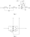
- The invention is explained by the drawings in which the given illustrations are possible but not limiting realizations of the current invention.
- Fig. 1
- - block-diagram of the device.
- Fig. 2
- - diagram of the β detection chamber.
- According to the present invention, a device for determination of specific activity of radiocarbon (14C) comprises: a
combustor 1, a water vapor andaerosol particle catcher 2, azeolitic catcher 3, an optic CO2 amount analyzer 4, a cryogenic CO2 catcher 5, achamber 6 of β-particles detection, a vacuum pump 7, a chemical CO2 catcher 8, two single-channel analyzers ofelectric pulse amplitude 9' and 9", ananti-coincidence circuit 10, anelectric pulse counter 11, adigital controller 12 andcarrier gas balloon 13. The Chamber of β-detection 6 comprises two semiconductor detectors in the shape ofdisks 14' and 14", which outputs correspondingly through the two single-channelpulse amplitude analyzers 9' and 9" are connected to theanti-coincidence circuit 10. Theanti-coincidence circuit 10 is configured to produce an output pulse when it receives a pulse from any one of thesemiconductor detectors 14' or 14" through the respectivepulse amplitude analyzers 9' or 9" and to suppress the output pulse when theanti-coincidence circuit 10 receives the pulses from bothdetectors 14' and 14" through thepulse amplitude analyzers 9' and 9", simultaneously. - Detailed description of at least one way of carrying out the invention where according to the invention the device is applied to determine the specific activity of 14C in the graphite samples.
- Sample of radioactive graphite is placed into the
combustor 1 which is maintained at the temperature of about +1000 °C in the air environment. The sample thus is converted into CO2 (gas), NOx oxides (gases) and H2O (gas). These compounds are further transferred into the system with carrier gas (N2, Ar or He) 13 which are supplied into the system through the controlled valves A and D. - As the next step, the compounds pass through the water vapor and
aerosol particle catcher 2. The catcher removes water vapor and aerosol particles while it transmits the CO2 gas. - Further the gas mixture that contains CO2, Rn and carrier gas (N2, Ar, He) passes from the water vapor and
aerosol particle catcher 2 into thezeolitic catcher 3 through the valves A and B for the thermal separation of radon (Rn) from CO2 to take place. Zeolitic catcher captures at least 95% of CO2 gas under room temperature, whereas other gases including Rn pass freely through the said catcher and are let out from the device through the open three-way valve C which is controlled by thedigital controller 12. The exhaust gases are then trapped by the gas catcher U1 and utilized. After the procedure of CO2 accumulation within the zeolitic catcher is complete,digital microcontroller 12 switches the valve C, whereaszeolitic catcher 3 is heated up to +70 °C and CO2 gas is released and passes through the valve C into the optic analyzer of CO2 amount 4. - Principle of operation of optic CO2 amount analyzer relies on the strong IR-light absorption by CO2 gas in the range of 4200-4400 nm wavelength. A non-coherent solid-state emitter of IR radiation in the range 4200-4400 nm is employed. By comparing the attenuated by CO2 gas IR signal to the initial IR signal, absorbance of a given CO2 sample is determined. By comparing the obtained absorbance of sample to the absorbance of known concentration of CO2 gas and taking into account the flow rate of carrier gas, the amount of CO2 gas in the sample is determined.
- The gas stream is further directed from the
analyzer 4 into thecryogenic catcher 5 which is cooled by liquid nitrogen at -196°C. There is also the controlled valve E in betweenanalyzer 4 andcatcher 5 and the said valve isolates thecatcher 5 from the rest of the system, as soon as the catcher collects the CO2 sample. - There is a three-way valve F installed downstream of the
cryogenic catcher 5, the said valve isolates thecryogenic catcher 5 from thedetection chamber 6 at the time of sample collection within thecryogenic catcher 5.Cryogenic catcher 5 featuresinternal volume 8 to 10 times smaller than the β -detection chamber 6, whereas thedetection chamber 6 takes the shape of a cylinder with internal dimensions h = 9 mm and d = 24 mm. - After CO2 gas is collected within the
cryogenic catcher 5, a two-way valve H is closed andcryogenic catcher 5 together with β-detection chamber 6 are vacuumed by means of the vacuum pump 7 through the three-way valve G in order to remove all residuals of carrier gas and to prepare the β-detection chamber 6 for the determination of 14C specific activity. As soon as the necessary depth of vacuum is achieved, valve G disconnects the vacuum pump from the system to avoid the surplus dead-volume of the system. Thecryogenic catcher 5 is then heated to - 88 °C, the previously collected CO2 sublimes from solid phase into the gas phase and freely diffuses between thecatcher 5 andchamber 6. After the equilibrium of CO2 concentration betweencatcher 5 andchamber 6 is achieved, determination of CO2 specific activity is started, that is, electric pulses are started to be counted. Given the fact that the detection chamber (6) is 8 to 10 times bigger than thecryogenic catcher 5, at least 80% of the sample occurs within thedetection chamber 6 which provides for the efficient detection. In order to achieve the desirable precision of measurement, duration of counting of pulses is continued until the moment when the counted number of pulses exceeds the pulses obtained due to the background radiation and electronic noise, that is, when the signal-to-noise ratio becomes greater than 1. - β -
detection chamber 6 comprises tosemiconductor detectors 14' and 14". Outputs of thedetectors 14' and 14" are correspondingly connected to two single-channelpulse amplitude analyzers 9' and 9". Outputs of the said analyzers are connected to theanti-coincidence circuit 10 which aims to suppress the pulses coming from both detectors simultaneously and to transfer output signals when the pulses come from only one of thedetectors 14' or 14" at a time. The output of theanti-coincidence circuit 10 is connected to thepulse counter 11. In the β-detection chamber 6, the two saiddetectors 14' and 14" are located opposite each other to form a geometry close to 4π. The said geometry is designed to cover the entire sphere around the gas being investigated, whereas, the radius of the sphere is equal or smaller than the mean free path of the β-particle. The 4π geometry thus enables one to record a particle and its energy independently from the direction of a particle movement. The two detectors produce the pulses that amplitude is proportional to the energy of the particle that has impacted a detector. The anti-coincidence circuit is configured so that it produces an output pulse only when the amplitude of the input pulse falls in the range from electronic noise up to the equivalent of maximum possible energy particle caused by 14C decay. In the case two pulses come from both detectors simultaneously, a ban signal is formed for thepulse counter 11 and therefore thecounter 11 will omit the given pulses. This ensures that only the pulses generated by β-decay of the sample are counted and the pulses coming from the external sources (like, from the cosmic rays) are omitted. Data treatment and control of the device is performed by thedigital controller 12. - Chemical CO2 catcher 8 containing 3 M NaOH solution is installed downstream of the β-
detector chamber 6. There is also a check-valve (I) installed immediately before thechemical catcher 8. The check-valve (I) prevents chemical reagents from flowing back from the chemical catcher into the system. The CO2 sample collected within a chemical catcher can further be used for radioactivity analysis by liquid scintillation counting (LSC) technique and for evaluation of the CO2 mass as well.
Claims (4)
- A device for determination of specific activity of radiocarbon (14C) comprising a combustor (1) which outlet is linked to a water vapor and aerosol particle catcher (2), a chemical CO2 catcher (8), a carrier gas balloon which supplies the carrier gas into the device system, and a β - particle detection system, characterized in that the device is provided with:- a zeolitic CO2 catcher (3) which inlet is linked to an outlet of the water vapor and aerosol particle catcher (2) through a controlled valve B, wherein outlet of said CO2 catcher (3) is linked to an optical CO2 amount analyzer (4) through a first outlet of a controlled valve C, wherein a second outlet of the valve C is intended to remove the discharged gases from the device,- a cryogenic CO2 catcher (5) which inlet is linked to an outlet of the optic CO2 amount analyzer (4) through controlled valves, while an outlet of said catcher (5) is linked to the β-particle detection system, which is a chamber (6) of β - particle detection, through a first outlet of a valve F, whereas a second outlet of the valve F is intended to remove the discharged gases from the device, whereinthe chamber (6) of β-particle detection comprises two semiconductor detectors (14' ir 14") which arrangement is close to the 4π - geometry and which is configured to produce electric pulses proportional to an energy of the detected β particles, the energy of produced electric pulses being in a range from an equivalent of an electronic noise to a maximum possible energy of β particles emitted during radioactive decay of 14C,the two semiconductor detectors (14' and 14") of the β-particle detection chamber (6) are connected correspondingly to two pulse amplitude single-channel analyzers (9' and 9") which outlets are connected to an anti-coincidence electronic circuit (10),the anti-coincidence circuit (10) is configured to produce an output pulse when it receives a pulse from any one of the semiconductor detectors (14`) or (14") through the respective pulse amplitude analyzer (9`) or (9"), and to suppress the output pulse when the anti-coincidence circuit (10) receives the pulses from both detectors (14`) and (14") through the pulse amplitude analyzers (9`) and (9") simultaneously,an output of the anti-coincidence circuit (10) is connected to a pulse counter (11) which is configured to count the pulses generated by β particles, whereas the number of counted pulses is used to evaluate the specific activity of 14C,the chamber (6) of β-particle detection is linked to the chemical CO2 cather (8) and to a vacuum pump (7) through the controlled valves,controller (12) is provided to perform data treatment and to control the device operation.
- The device according to claim 1, characterized in that the optic CO2 amount analyzer (4) is configured to measure the light absorption in the gas stream, said light absorption, being dependent on CO2 concentration data, are time integrated, where the value of the integral is proportional to an amount of CO2 that has passed through the device system over the integrated time period.
- The device according to claim 1 or 2, characterized in that the geometry of the chamber (6) of β-particle detection is cylindrical and the detectors are disc-shaped, wherein the distance h between detectors 14` and 14" is about 2,5 times smaller than their diameter d.
- A System for the determination of specific activity of radiocarbon 14C comprising any device according to any one of claims 1 - 3.
Applications Claiming Priority (1)
| Application Number | Priority Date | Filing Date | Title |
|---|---|---|---|
| LT2022519A LT7039B (en) | 2022-05-04 | 2022-05-04 | Radiocarbon (14C) specific activity determination device |
Publications (3)
| Publication Number | Publication Date |
|---|---|
| EP4273590A1 true EP4273590A1 (en) | 2023-11-08 |
| EP4273590B1 EP4273590B1 (en) | 2025-11-26 |
| EP4273590C0 EP4273590C0 (en) | 2025-11-26 |
Family
ID=85724884
Family Applications (1)
| Application Number | Title | Priority Date | Filing Date |
|---|---|---|---|
| EP23163010.4A Active EP4273590B1 (en) | 2022-05-04 | 2023-03-21 | Device for determination of specific activity of radiocarbon (14c) |
Country Status (2)
| Country | Link |
|---|---|
| EP (1) | EP4273590B1 (en) |
| LT (1) | LT7039B (en) |
Citations (1)
| Publication number | Priority date | Publication date | Assignee | Title |
|---|---|---|---|---|
| US4187428A (en) * | 1977-05-17 | 1980-02-05 | Instytut Baden Jadrowych | Method and apparatus for absolute activity determination of radionuclides |
-
2022
- 2022-05-04 LT LT2022519A patent/LT7039B/en unknown
-
2023
- 2023-03-21 EP EP23163010.4A patent/EP4273590B1/en active Active
Patent Citations (1)
| Publication number | Priority date | Publication date | Assignee | Title |
|---|---|---|---|---|
| US4187428A (en) * | 1977-05-17 | 1980-02-05 | Instytut Baden Jadrowych | Method and apparatus for absolute activity determination of radionuclides |
Non-Patent Citations (1)
| Title |
|---|
| REMEIKIS VIDMANTAS ET AL: "Rapid analysis method for the determination of 14C specific activity in irradiated graphite", PLOS ONE, vol. 13, no. 1, 25 January 2018 (2018-01-25), pages e0191677, XP093076315, DOI: 10.1371/journal.pone.0191677 * |
Also Published As
| Publication number | Publication date |
|---|---|
| LT7039B (en) | 2023-12-27 |
| EP4273590B1 (en) | 2025-11-26 |
| LT2022519A (en) | 2023-11-10 |
| EP4273590C0 (en) | 2025-11-26 |
Similar Documents
| Publication | Publication Date | Title |
|---|---|---|
| EP2120065A2 (en) | Scintillation-Based Continuous Monitor for Beta-Emitting Radionuclides in a Liquid Medium | |
| RU2676557C1 (en) | Radioactive aerosols disperse composition parameters determining method | |
| CN109991647B (en) | Application method of radioactive xenon rapid high-sensitivity detection device | |
| EP4273590A1 (en) | Device for determination of specific activity of radiocarbon (14c) | |
| Campbell et al. | Radiocarbon tracer measurements of atmospheric hydroxyl radical concentrations | |
| US4835395A (en) | Continuous aqueous tritium monitor | |
| JPH09511336A (en) | Apparatus and method for measuring tritium by gas scintillation | |
| USH188H (en) | Monitor for airborne dusts | |
| US5552610A (en) | Device and method for accurately measuring concentrations of airborne transuranic isotopes | |
| Bowyer et al. | Automatic radioxenon analyzer for CTBT monitoring | |
| GB2106641A (en) | Monitoring radon and thoron daughters | |
| US5319955A (en) | Tritium monitor | |
| CN110161139A (en) | A kind of large volume non-quantitative sample injection method using gas chromatograph separation Kr-85 | |
| RU2189612C1 (en) | Method for testing of enrichment of gaseous uranium hexafluoride by uranium-235 | |
| Yule | An on-line monitor for alpha-emitting aerosols | |
| RU2185667C1 (en) | Method and system for checking enrichment of uranium hexafluoride | |
| Beach et al. | A real-time tritium monitor with an MPC proportional response to airborne mixtures of TH and THO | |
| Olmez et al. | Nondestructive analysis for silicon, rubidium, and yttrium in atomspheric particulate material | |
| Engelmann et al. | New method to measure oxygen isotopic concentration ratios18O/16O by gamma-activation analysis, especially in biological media | |
| Perrin | AVIRTUAL IMPACTOR FOR PERSONAL AND AREA AIR SAMPLING | |
| JPH09288185A (en) | Sampler for radiation detection | |
| SU766298A1 (en) | Method for measuring neutron half-life period | |
| JPS5977346A (en) | Analyzing apparatus for element composition of substance | |
| Rusch et al. | The ZPR-9 Airborne Plutonium Monitoring System | |
| JPH0666948A (en) | Radioactive gas leak rate inspection device |
Legal Events
| Date | Code | Title | Description |
|---|---|---|---|
| PUAI | Public reference made under article 153(3) epc to a published international application that has entered the european phase |
Free format text: ORIGINAL CODE: 0009012 |
|
| STAA | Information on the status of an ep patent application or granted ep patent |
Free format text: STATUS: THE APPLICATION HAS BEEN PUBLISHED |
|
| AK | Designated contracting states |
Kind code of ref document: A1 Designated state(s): AL AT BE BG CH CY CZ DE DK EE ES FI FR GB GR HR HU IE IS IT LI LT LU LV MC ME MK MT NL NO PL PT RO RS SE SI SK SM TR |
|
| STAA | Information on the status of an ep patent application or granted ep patent |
Free format text: STATUS: REQUEST FOR EXAMINATION WAS MADE |
|
| 17P | Request for examination filed |
Effective date: 20240425 |
|
| RBV | Designated contracting states (corrected) |
Designated state(s): AL AT BE BG CH CY CZ DE DK EE ES FI FR GB GR HR HU IE IS IT LI LT LU LV MC ME MK MT NL NO PL PT RO RS SE SI SK SM TR |
|
| GRAP | Despatch of communication of intention to grant a patent |
Free format text: ORIGINAL CODE: EPIDOSNIGR1 |
|
| STAA | Information on the status of an ep patent application or granted ep patent |
Free format text: STATUS: GRANT OF PATENT IS INTENDED |
|
| INTG | Intention to grant announced |
Effective date: 20250910 |
|
| GRAS | Grant fee paid |
Free format text: ORIGINAL CODE: EPIDOSNIGR3 |
|
| GRAA | (expected) grant |
Free format text: ORIGINAL CODE: 0009210 |
|
| STAA | Information on the status of an ep patent application or granted ep patent |
Free format text: STATUS: THE PATENT HAS BEEN GRANTED |
|
| AK | Designated contracting states |
Kind code of ref document: B1 Designated state(s): AL AT BE BG CH CY CZ DE DK EE ES FI FR GB GR HR HU IE IS IT LI LT LU LV MC ME MK MT NL NO PL PT RO RS SE SI SK SM TR |
|
| REG | Reference to a national code |
Ref country code: CH Ref legal event code: F10 Free format text: ST27 STATUS EVENT CODE: U-0-0-F10-F00 (AS PROVIDED BY THE NATIONAL OFFICE) Effective date: 20251126 Ref country code: GB Ref legal event code: FG4D |
|
| REG | Reference to a national code |
Ref country code: DE Ref legal event code: R096 Ref document number: 602023008875 Country of ref document: DE |
|
| REG | Reference to a national code |
Ref country code: IE Ref legal event code: FG4D |
|
| U01 | Request for unitary effect filed |
Effective date: 20251213 |
|
| U07 | Unitary effect registered |
Designated state(s): AT BE BG DE DK EE FI FR IT LT LU LV MT NL PT RO SE SI Effective date: 20251219 |
|
| PG25 | Lapsed in a contracting state [announced via postgrant information from national office to epo] |
Ref country code: ES Free format text: LAPSE BECAUSE OF FAILURE TO SUBMIT A TRANSLATION OF THE DESCRIPTION OR TO PAY THE FEE WITHIN THE PRESCRIBED TIME-LIMIT Effective date: 20251126 |
|
| PG25 | Lapsed in a contracting state [announced via postgrant information from national office to epo] |
Ref country code: NO Free format text: LAPSE BECAUSE OF FAILURE TO SUBMIT A TRANSLATION OF THE DESCRIPTION OR TO PAY THE FEE WITHIN THE PRESCRIBED TIME-LIMIT Effective date: 20260226 |
|
| PG25 | Lapsed in a contracting state [announced via postgrant information from national office to epo] |
Ref country code: HR Free format text: LAPSE BECAUSE OF FAILURE TO SUBMIT A TRANSLATION OF THE DESCRIPTION OR TO PAY THE FEE WITHIN THE PRESCRIBED TIME-LIMIT Effective date: 20251126 |
|
| U20 | Renewal fee for the european patent with unitary effect paid |
Year of fee payment: 4 Effective date: 20260312 |
|
| PG25 | Lapsed in a contracting state [announced via postgrant information from national office to epo] |
Ref country code: RS Free format text: LAPSE BECAUSE OF FAILURE TO SUBMIT A TRANSLATION OF THE DESCRIPTION OR TO PAY THE FEE WITHIN THE PRESCRIBED TIME-LIMIT Effective date: 20260226 |
|
| PG25 | Lapsed in a contracting state [announced via postgrant information from national office to epo] |
Ref country code: IS Free format text: LAPSE BECAUSE OF FAILURE TO SUBMIT A TRANSLATION OF THE DESCRIPTION OR TO PAY THE FEE WITHIN THE PRESCRIBED TIME-LIMIT Effective date: 20260326 |
|
| PG25 | Lapsed in a contracting state [announced via postgrant information from national office to epo] |
Ref country code: PL Free format text: LAPSE BECAUSE OF FAILURE TO SUBMIT A TRANSLATION OF THE DESCRIPTION OR TO PAY THE FEE WITHIN THE PRESCRIBED TIME-LIMIT Effective date: 20251126 |