EP4273565B1 - Batterieabtastungschip und batterieverwaltungssystem - Google Patents
Batterieabtastungschip und batterieverwaltungssystem Download PDFInfo
- Publication number
- EP4273565B1 EP4273565B1 EP21958677.3A EP21958677A EP4273565B1 EP 4273565 B1 EP4273565 B1 EP 4273565B1 EP 21958677 A EP21958677 A EP 21958677A EP 4273565 B1 EP4273565 B1 EP 4273565B1
- Authority
- EP
- European Patent Office
- Prior art keywords
- multiplexer
- analog
- digital
- module
- data
- Prior art date
- Legal status (The legal status is an assumption and is not a legal conclusion. Google has not performed a legal analysis and makes no representation as to the accuracy of the status listed.)
- Active
Links
Images

Classifications
-
- G—PHYSICS
- G01—MEASURING; TESTING
- G01R—MEASURING ELECTRIC VARIABLES; MEASURING MAGNETIC VARIABLES
- G01R31/00—Arrangements for testing electric properties; Arrangements for locating electric faults; Arrangements for electrical testing characterised by what is being tested not provided for elsewhere
- G01R31/36—Arrangements for testing, measuring or monitoring the electrical condition of accumulators or electric batteries, e.g. capacity or state of charge [SoC]
- G01R31/396—Acquisition or processing of data for testing or for monitoring individual cells or groups of cells within a battery
-
- G—PHYSICS
- G01—MEASURING; TESTING
- G01R—MEASURING ELECTRIC VARIABLES; MEASURING MAGNETIC VARIABLES
- G01R19/00—Arrangements for measuring currents or voltages or for indicating presence or sign thereof
- G01R19/165—Indicating that current or voltage is either above or below a predetermined value or within or outside a predetermined range of values
- G01R19/16533—Indicating that current or voltage is either above or below a predetermined value or within or outside a predetermined range of values characterised by the application
- G01R19/16538—Indicating that current or voltage is either above or below a predetermined value or within or outside a predetermined range of values characterised by the application in AC or DC supplies
- G01R19/16542—Indicating that current or voltage is either above or below a predetermined value or within or outside a predetermined range of values characterised by the application in AC or DC supplies for batteries
-
- G—PHYSICS
- G01—MEASURING; TESTING
- G01R—MEASURING ELECTRIC VARIABLES; MEASURING MAGNETIC VARIABLES
- G01R35/00—Testing or calibrating of apparatus covered by the other groups of this subclass
-
- H—ELECTRICITY
- H01—ELECTRIC ELEMENTS
- H01M—PROCESSES OR MEANS, e.g. BATTERIES, FOR THE DIRECT CONVERSION OF CHEMICAL ENERGY INTO ELECTRICAL ENERGY
- H01M10/00—Secondary cells; Manufacture thereof
- H01M10/42—Methods or arrangements for servicing or maintenance of secondary cells or secondary half-cells
- H01M10/425—Structural combination with electronic components, e.g. electronic circuits integrated to the outside of the casing
-
- H—ELECTRICITY
- H01—ELECTRIC ELEMENTS
- H01M—PROCESSES OR MEANS, e.g. BATTERIES, FOR THE DIRECT CONVERSION OF CHEMICAL ENERGY INTO ELECTRICAL ENERGY
- H01M10/00—Secondary cells; Manufacture thereof
- H01M10/42—Methods or arrangements for servicing or maintenance of secondary cells or secondary half-cells
- H01M10/48—Accumulators combined with arrangements for measuring, testing or indicating the condition of cells, e.g. the level or density of the electrolyte
- H01M10/482—Accumulators combined with arrangements for measuring, testing or indicating the condition of cells, e.g. the level or density of the electrolyte for several batteries or cells simultaneously or sequentially
-
- G—PHYSICS
- G01—MEASURING; TESTING
- G01R—MEASURING ELECTRIC VARIABLES; MEASURING MAGNETIC VARIABLES
- G01R19/00—Arrangements for measuring currents or voltages or for indicating presence or sign thereof
- G01R19/25—Arrangements for measuring currents or voltages or for indicating presence or sign thereof using digital measurement techniques
-
- H—ELECTRICITY
- H01—ELECTRIC ELEMENTS
- H01M—PROCESSES OR MEANS, e.g. BATTERIES, FOR THE DIRECT CONVERSION OF CHEMICAL ENERGY INTO ELECTRICAL ENERGY
- H01M10/00—Secondary cells; Manufacture thereof
- H01M10/42—Methods or arrangements for servicing or maintenance of secondary cells or secondary half-cells
- H01M10/425—Structural combination with electronic components, e.g. electronic circuits integrated to the outside of the casing
- H01M2010/4271—Battery management systems including electronic circuits, e.g. control of current or voltage to keep battery in healthy state, cell balancing
Definitions
- the present application relates to the technical field of batteries, in particular to a battery sampling chip as specified in any of claim 1-9 and a battery management system in claim 10.
- the battery management system collects voltage and temperature data of the battery through a battery sampling chip.
- An inventor found in the research that reliability of a current battery sampling chip, such as an analog front end (AFE) sampling chip, is low. When the AFE sampling chip fails or is abnormal, the data collected by it is usually invalid data. The existing technology cannot identify the invalid data in time, resulting in a dangerous monitoring status of the battery management system.
- AFE analog front end
- An objective of an embodiment of the present application is to provide a battery sampling chip and a battery management system, so as to timely identify incorrect data collected by the battery sampling chip due to its own failure or abnormality, so as to ensure safety monitoring of the battery management system.
- an embodiment of the present application provides a battery sampling chip as specified in any of claim 1-9, including: a selector module, including: a first multiplexer and a second multiplexer, the first multiplexer and the second multiplexer being both used to collect status data of a first group of cells; an analog-to-digital conversion module, connected with the first multiplexer and the second multiplexer, the analog-to-digital conversion module being used to send a first abnormality feedback instruction to the first multiplexer and the second multiplexer when the status data of the first group of cells respectively collected by the first multiplexer and the second multiplexer are different, and perform analog-to-digital conversion on the status data of the first group of cells when the status data of the first group of cells respectively collected by the first multiplexer and the second multiplexer are the same; and a data control module, connected with the analog-to-digital conversion module, the data control module being used to receive converted status data sent by the analog-to-digital conversion module, and send alarm information when the
- the selector module in the battery sampling chip includes two multiplexers both used to collect the status data of the first group of cells.
- the status data of the first group of cells collected by the two multiplexers are inconsistent, it represents that the selector module fails or is abnormal, and incorrect sampling data will not be output at this time. It can be seen that through redundancy design of the multiplexers, whether the selector module fails or is abnormal can be effectively judged, thus avoiding the battery management system including the battery sampling chip from monitoring incorrect status data.
- the battery sampling chip provided by the embodiments of the present application enhances safety of the battery management system while improving its own reliability.
- the selector module further includes a third multiplexer and a fourth multiplexer; the third multiplexer and the fourth multiplexer are both used to collect status data of a second group of cells, the first group of cells and the second group of cells include the same first cell, and the first group of cells and the second group of cells belong to the same device; and the analog-to-digital conversion module is further connected with the third multiplexer and the fourth multiplexer, the analog-to-digital conversion module is further used to send a second abnormality feedback instruction to the third multiplexer and the fourth multiplexer when the status data of the second group of cells respectively collected by the third multiplexer and the fourth multiplexer are different; send a third abnormality feedback instruction to the first multiplexer, the second multiplexer, the third multiplexer and the fourth multiplexer when status data of the first cell respectively collected by the first multiplexer, the second multiplexer, the third multiplexer and the fourth multiplexer are different; and
- the selector module further includes the third multiplexer and the fourth multiplexer, the third multiplexer and the fourth multiplexer are both used to collect the status data of the second group of cells, and the first group of cells and the second group of cells include the same first cell.
- the same first cell cross verification of the status data collected among the first multiplexer, the second multiplexer, the third multiplexer and the fourth multiplexer can be realized, whether the first multiplexer and the second multiplexer fail at the same time or whether the third multiplexer and the fourth multiplexer fail at the same time can be effectively verified, and thus when a group of multiplexers fail, abnormal sampling data will not be output, thereby further improving the reliability of the battery sampling chip.
- the analog-to-digital conversion module includes a first analog-to-digital converter, a second analog-to-digital converter and a sampling data comparison unit; the first analog-to-digital converter and the second analog-to-digital converter are two analog-to-digital converters with different precision; the first analog-to-digital converter and the second analog-to-digital converter are both connected with the first multiplexer, the second multiplexer and the sampling data comparison unit; and the sampling data comparison unit is further connected with the data control module; the first analog-to-digital converter and the second analog-to-digital converter are both used to perform analog-to-digital conversion on the status data of the first group of cells; and the sampling data comparison unit is used to obtain digital quantities converted by the first analog-to-digital converter and the second analog-to-digital converter, and convert the two digital quantities into digital quantities under first precision respectively; send the digital quantities under the first precision to the data control module when the two digital quantities
- the analog-to-digital conversion module also adopts the redundancy design, and the first analog-to-digital converter and the second analog-to-digital converter are the two analog-to-digital converters with different precision. In this way, abnormal data output in a conversion process due to common mode failure of the analog-to-digital converters can be effectively avoided.
- the first analog-to-digital converter is an 11-bit analog-to-digital converter
- the second analog-to-digital converter is a 16-bit analog-to-digital converter
- the sampling data comparison unit is further used to lock a faulty analog-to-digital converter when the two digital quantities under the first precision are different, and the faulty analog-to-digital converter is an analog-to-digital converter corresponding to the digital quantity with a large difference value from a preset quantity in the two digital quantities under the first precision.
- the sampling data comparison unit may further lock the faulty analog-to-digital converter, so that subsequent maintenance personnel carry out maintenance directly and save the fault detection time of the maintenance personnel.
- the battery sampling chip further includes a reference voltage calibration module; the reference voltage calibration module is respectively connected with the analog-to-digital conversion module and the data control module; and the reference voltage calibration module is used to collect a power supply voltage of the battery sampling chip and a power supply voltage of the analog-to-digital conversion module; and compare the power supply voltage of the battery sampling chip with the power supply voltage of the analog-to-digital conversion module, and trigger the data control module to alarm when the comparison result is inconsistent.
- the battery sampling chip further includes the reference voltage calibration module, and the reference voltage calibration module is connected with the analog-to-digital conversion module.
- the reference voltage calibration module Through the reference voltage calibration module, whether the power supply voltage of the analog-to-digital conversion module is abnormal can be effectively identified, thus avoiding a case that sampling precision of the battery sampling chip is inaccurate due to interference of environmental factors, and further improving the reliability of the battery sampling chip.
- the reference voltage calibration module is further connected with the selector module, and the reference voltage calibration module is further used to collect a power supply voltage of the selector module, compare the power supply voltage of the battery sampling chip with the power supply voltage of the selector module, and trigger the data control module to alarm when the comparison result is inconsistent.
- the reference voltage calibration module is further connected with the selector module.
- the selector module Through the reference voltage calibration module, whether the power supply voltage of the selector module is abnormal can be effectively identified, thus avoiding the case that sampling precision of the battery sampling chip is inaccurate due to interference of environmental factors, and further improving the reliability of the battery sampling chip.
- the battery sampling chip further includes a sleep detection module; and the sleep detection module is respectively connected with the analog-to-digital conversion module and the data control module, and the sleep detection module is used to compare the converted status data transmitted by the analog-to-digital conversion module with a preset value when a device connected with the battery sampling chip is in a sleep state, and trigger the data control module to alarm when the comparison result is inconsistent.
- the battery sampling chip is further integrated with the sleep detection module, which can save space resources and energy consumption of a controller compared with the prior art that a sleep detection module is arranged in a controller of a battery management system.
- the status data include voltage data and/or temperature data.
- an embodiment of the present application provides a battery management system, including a controller and the battery sampling chip provided in the embodiment of the first aspect above, wherein the controller is connected with the data control module of the battery sampling chip, and the controller is used to obtain status data of a battery collected by the battery sampling chip.
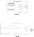
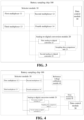
- Icon 100-Battery sampling chip; 10-Selector module; 11-First multiplexer; 12-Second multiplexer; 13-Third multiplexer; 14-Fourth multiplexer; 20-Analog-to-digital conversion module; 21-First analog-to-digital converter; 22-Second analog-to-digital converter; 23-Sampling data comparison unit; 30-Data control module; 40-Reference voltage calibration module; 50-Sleep detection module; 200-Battery management system; and 300-Controller.
- an embodiment of the present application provides a battery sampling chip 100, including a selector module 10, an analog-to-digital conversion module 20 and a data control module 30.
- the analog-to-digital conversion module 20 is connected with the selector module 10 and the data control module 30 respectively.
- the selector module 10 is mainly used to collect status data of a battery, and the battery includes a plurality of cells.
- the selector module 10 includes a first multiplexer 11 and a second multiplexer 12.
- the first multiplexer 11 is connected with the second multiplexer 12.
- the first multiplexer 11 and the second multiplexer 12 are both used to collect status data of a first group of cells.
- the first group of cells may refer to all cells in the battery, or some cells in the battery. When the first group of cells is part of the cells in the battery, the selector module 10 further includes more multiplexers to sample other cells.
- the multiplexer is a multi-input and single-output combined logic circuit. Therefore, one multiplexer may simultaneously sample the plurality of cells.
- the first group of cells includes eight cells, and the first multiplexer 11 and the second multiplexer 12 may simultaneously collect the status data of the eight cells.
- the status data of the cells may be either voltage data of the cells or temperature data of the cells.
- the battery sampling chip 100 may also sample the voltage data and the temperature data of the cells simultaneously, which is not limited by the present application.
- the analog-to-digital conversion module 20 is mainly used for conversion of an analog quantity and a digital quantity.
- the analog-to-digital conversion module 20 is connected with the first multiplexer 11 and the second multiplexer 12.
- the analog-to-digital conversion module 20 is used to send a first abnormality feedback instruction to the first multiplexer 11 and the second multiplexer 12 when the status data of the first group of cells respectively collected by the first multiplexer 11 and the second multiplexer 12 are different, and perform analog-to-digital conversion on the status data of the first group of cells when the status data of the first group of cells respectively collected by the first multiplexer 11 and the second multiplexer 12 are the same.
- the first multiplexer 11 and the second multiplexer 12 are both used to collect the status data of a number-one cell to a number-eight cell.
- the analog-to-digital conversion module 20 receives the different status data of the number-one cell to the number-eight cell collected by the first multiplexer and the second multiplexer, it represents that the selector module 10 fails or is abnormal.
- analog-to-digital conversion is not performed on the collected status data (that is, incorrect sampling data will not be output), instead, the first abnormality feedback instruction is sent to the first multiplexer 11 and the second multiplexer 12.
- analog-to-digital conversion module 20 When the analog-to-digital conversion module 20 receives the same status data of the number-one cell to the number-eight cell collected by the first multiplexer and the second multiplexer, it represents that the selector module 10 in a normal work state. At this time, analog-to-digital conversion is performed on the status data of the first group of cells. When the status data are the same, it may be set at this time that analog-to-digital conversion is performed according to the status data collected by any multiplexer. For example, it may be set that the analog-to-digital conversion is performed based on the status data of the first group of cells collected by the first multiplexer 11.
- whether the status data are the same may be judged by one preset comparison threshold. For example, when a difference value between the status data respectively collected by the first multiplexer 11 and the second multiplexer 12 is less than the preset comparison threshold, it represents that the status data collected by the two are the same, and when the difference value between the status data respectively collected by the first multiplexer 11 and the second multiplexer 12 is greater than the preset comparison threshold, the status data collected by the two are different.
- a specific value of the preset comparison threshold may be determined according to the actual situation, and the value is not limited here.
- the data control module 30 is connected with the analog-to-digital conversion module 20.
- the data control module 30 is used to receive converted status data sent by the analog-to-digital conversion module 20, and send alarm information when the converted status data sent by the analog-to-digital conversion module 20 is not received within a preset duration.
- the data control module 30 contains two data control modes.
- the first mode is that the analog-to-digital conversion module 20 does not detect the abnormality of the selector module 10, at this time, the data control module 30 can receive the converted status data sent by the analog-to-digital conversion module 20, so that the data control module 30 subsequently outputs the converted status data to a controller of the battery management system connected with the battery sampling chip 100, wherein, the data control module 30 may include a data register unit to store the converted status data.
- the data control module 30 does not receive the converted status data sent by the analog-to-digital conversion module 20 within the preset duration, it means that the collected data are interrupted at the analog-to-digital conversion module 20, that is, the status data collected by the selector module 10 are incorrect. At this time, the data control module 30 sends the alarm information.
- a specific value of the preset duration above may be determined according to the actual situation, and the value is not limited here.
- the selector module 10 in the battery sampling chip 100 includes two multiplexers both used to collect the status data of the first group of cells.
- the status data of the first group of cells collected by the two multiplexers are inconsistent, it represents that the selector module fails or is abnormal, and the incorrect sampling data will not be output at this time. It can be seen that through redundancy design of the multiplexers, whether the selector module 10 fails or is abnormal can be effectively judged, thus avoiding the battery management system including the battery sampling chip 100 from monitoring the incorrect status data.
- the battery sampling chip 100 provided by the embodiments of the present application enhances the safety of the battery management system while improving its reliability.
- the selector module 10 further includes a third multiplexer 13 and a fourth multiplexer 14.
- the third multiplexer 13 is connected with the fourth multiplexer 14, and the third multiplexer 13 and the fourth multiplexer 14 are further connected with the first multiplexer 11 and the second multiplexer 12, that is, the four multiplexers are connected.
- the third multiplexer 13 and the fourth multiplexer 14 are both used to collect status data of a second group of cells.
- the first group of cells and the second group of cells include the same first cell, and the first group of cells and the second group of cells belong to the same device.
- the first group of cells and the second group of cells belong to the same new energy vehicle.
- the new energy vehicle includes 16 cells.
- the 16 cells are numbered in order to obtain the number-one cell to a number-sixteen cell.
- the first group of cells is the number-one cell to a number-ten cell
- the second group of cells is the number-ten cell to the number-sixteen cell.
- the number-ten cell is the first cell.
- the first multiplexer 11, the second multiplexer 12, the third multiplexer 13 and the fourth multiplexer 14 will collect the status data of the number-ten cell.
- the analog-to-digital conversion module 20 is further connected with the third multiplexer 13 and the fourth multiplexer 14.
- the analog-to-digital conversion module 20 is further used to send a second abnormality feedback instruction to the third multiplexer 13 and the fourth multiplexer 14 when the status data of the second group of cells respectively collected by the third multiplexer 13 and the fourth multiplexer 14 are different; send a third abnormality feedback instruction to the first multiplexer 11, the second multiplexer 12, the third multiplexer 13 and the fourth multiplexer 14 when status data of the first cell respectively collected by the first multiplexer 11, the second multiplexer 12, the third multiplexer 13 and the fourth multiplexer 14 are different; and perform analog-to-digital conversion on the status data of the second group of cells when the status data of the second group of cells respectively collected by the third multiplexer 13 and the fourth multiplexer 14 are the same.
- the selector module 10 simultaneously includes the first multiplexer 11, the second multiplexer 12, the third multiplexer 13 and the fourth multiplexer 14, there will be four processing cases for the analog-to-digital conversion module 20.
- the first case is that when the status data of the first group of cells collected by the first multiplexer 11 and the second multiplexer 12 are the same, the status data of the second group of cells collected by the third multiplexer 13 and the fourth multiplexer 14 are the same, and the status data of the first cell collected by the first multiplexer 11, the second multiplexer 12, the third multiplexer 13 and the fourth multiplexer 14 are the same as well, the analog-to-digital conversion module 20 performs analog-to-digital conversion on the status data of the first group of cells and the status data of the second group of cells respectively.
- the second case is that when the status data of the first group of cells collected by the first multiplexer 11 and the second multiplexer 12 are different, and the status data of the second group of cells collected by the third multiplexer 13 and the fourth multiplexer 14 are the same, the analog-to-digital conversion module 20 sends the first abnormality feedback instruction to the first multiplexer 11 and the second multiplexer 12.
- the third case is that when the status data of the first group of cells collected by the first multiplexer 11 and the second multiplexer 12 are the same, and the status data of the second group of cells collected by the third multiplexer 13 and the fourth multiplexer 14 are different, the analog-to-digital conversion module 20 sends the second abnormality feedback instruction to the third multiplexer 11 and the fourth multiplexer 12.
- the fourth case is that when the status data of the first cell respectively collected by the first multiplexer 11, the second multiplexer 12, the third multiplexer 13 and the fourth multiplexer 14 are different, a third abnormality feedback instruction is sent to the first multiplexer 11, the second multiplexer 12, the third multiplexer 13 and the fourth multiplexer 14. It should be noted that in the fourth case, whether the status data of the first cell collected by the first multiplexer 11 and the second multiplexer 12 are the same as the status data of the first cell collected by the third multiplexer 13 and the fourth multiplexer 14 is mainly judged.
- the selector module 10 in the embodiment of the present application further includes the third multiplexer 13 and the fourth multiplexer 14, the third multiplexer 13 and the fourth multiplexer 14 are both used to collect the status data of the second group of cells, and the first group of cells and the second group of cells contain the same first cell.
- multiplexers may further be integrated in the selector module 10 to adapt to more cells.
- the number of the cells collected by each multiplexer may also be determined according to the actual situation, which is not limited in the present application.
- the analog-to-digital conversion module 20 includes a first analog-to-digital converter 21, a second analog-to-digital converter 22 and a sampling data comparison unit 23.
- the first analog-to-digital converter 21 and the second analog-to-digital converter 22 are two analog-to-digital converters (ADC) with different precision.
- the first analog-to-digital converter 21 and the second analog-to-digital converter 22 are both connected with the first multiplexer 11, the second multiplexer 12 and the sampling data comparison unit 23.
- the sampling data comparison unit 23 is further connected with the data control module 30.
- the first analog-to-digital converter 21 and the second analog-to-digital converter 22 are both used to perform analog-to-digital conversion on the status data of the first group of cells.
- the sampling data comparison unit 23 is used to obtain digital quantities converted by the first analog-to-digital converter 21 and the second analog-to-digital converter 22, and convert the two digital quantities into digital quantities under first precision respectively; send the digital quantities under the first precision to the data control module 30 when the two digital quantities under the first precision are the same, at this time, the digital quantities under the first precision being the converted status data received by the data control module 30; and trigger the data control module 30 to alarm when the two digital quantities under the first precision are different.
- the first analog-to-digital converter 21 performs analog-to-digital conversion on the status data of the first group of cells to obtain a digital quantity A
- the second analog-to-digital converter 22 performs analog-to-digital conversion on the status data of the first group of cells to obtain a digital quantity B.
- the sampling data comparison unit 23 converts them into the digital quantities under the same precision (first precision). For example, the sampling data comparison unit 23 converts the digital quantity A to into a digital quantity C1 under the first precision, and the sampling data comparison unit 23 converts the digital quantity B into a digital quantity C2 under the first precision.
- the first analog-to-digital converter 21 may be abnormal
- the second analog-to-digital converter 22 may be abnormal
- the first analog-to-digital converter 21 and the second analog-to-digital converter 22 may be abnormal at the same time.
- the first analog-to-digital converter 21 is an 11-bit analog-to-digital converter
- the second analog-to-digital converter 22 is a 16-bit analog-to-digital converter.
- the first precision above may refer to 12 bits, 11 bits or 16 bits.
- the first analog-to-digital converter 21 or the second analog-to-digital converter 22 may also be a 12-bit analog-to-digital converter, which is not limited in the present application.
- the analog-to-digital conversion module 20 also adopts the redundancy design, and the first analog-to-digital converter 21 and the second analog-to-digital converter 22 are the two analog-to-digital converters with different precision. In this way, abnormal data output in a conversion process due to common mode failure of the analog-to-digital converters can be effectively avoided.
- the sampling data comparison unit 23 is further used to lock the fault analog-to-digital converter when the two digital quantities under the first precision are different.
- the faulty analog-to-digital converter is an analog-to-digital converter corresponding to the digital quantity with a large difference value from a preset quantity in the two digital quantities under the first precision.
- the preset quantity is a digital quantity under the first precision corresponding to normal status data.
- the preset quantity is a digital quantity under the first precision corresponding to normal voltage data.
- the preset quantity is a digital quantity under the first precision corresponding to normal temperature data.
- the selector module 10 further includes the third multiplexer 13 and the fourth multiplexer 14
- the first analog-to-digital converter 21 and the second analog-to-digital converter 22 are both further connected with the third multiplexer 13 and the fourth multiplexer 14.
- the specific conversion process and sampling data comparison process please refer to the aforementioned process of analog-digital conversion and data comparison for the status data of the first group of cells, which is not repeated here.
- the battery sampling chip 100 further includes a reference voltage calibration module 40.
- the reference voltage calibration module 40 is connected with the analog-to-digital conversion module 20 and the data control module 30 respectively.
- the reference voltage calibration module 40 is used to collect a power supply voltage of the battery sampling chip 100 and a power supply voltage of the analog-to-digital conversion module 20; and compare the power supply voltage of the battery sampling chip 100 with the power supply voltage of the analog-to-digital conversion module 20, and trigger the data control module 30 to alarm when the comparison result is inconsistent.
- whether the power supply voltage of the analog-to-digital conversion module 20 is abnormal can be effectively identified, thus avoiding the case that sampling precision of the battery sampling chip 100 is inaccurate due to interference of environmental factors, and further improving the reliability of the battery sampling chip 100.
- the reference voltage calibration module 40 is further connected with the selector module 10.
- the reference voltage calibration module 40 is further used to collect a power supply voltage of the selector module 10, compare the power supply voltage of the battery sampling chip 100 with the power supply voltage of the selector module 10, and trigger the data control module 30 to alarm when the comparison result is inconsistent. Through the reference voltage calibration module 40, whether the power supply voltage of the selector module 10 is abnormal can be effectively identified, thus avoiding the case that sampling precision of the battery sampling chip 100 is inaccurate due to interference of environmental factors, and further improving the reliability of the battery sampling chip 100.
- the battery sampling chip 100 further includes a sleep detection module 50.
- the sleep detection module 50 is connected with the analog-to-digital conversion module 20 and the data control module 30 respectively.
- the sleep detection module 50 is used to compare the converted status data transmitted by the analog-to-digital conversion module 20 with a preset value when a device connected with the battery sampling chip is in a sleep state, and trigger the data control module 30 to alarm when the comparison result is inconsistent.
- the above preset value is a digital quantity corresponding to the status data during normal sleep.
- the preset value is a digital quantity corresponding to the voltage data during normal sleep.
- the preset value is a digital quantity corresponding to temperature data during normal sleep.
- the sleep detection module 50 is also integrated in the battery sampling chip 100, which can save space resources and energy consumption of a controller compared with the prior art that a sleep detection module 50 is arranged in a controller of a battery management system.
- an embodiment of the present application further provides a battery management system 200.
- the battery management system 200 includes a controller 300 and the battery sampling chip 100 provided by the above embodiment.
- the controller 300 is connected with a data control module 30 of the battery sampling chip 100, and the controller 300 is used to obtain status data of a battery collected by the battery sampling chip 100.
- the controller 300 When the battery includes a first group of cells, the controller 300 is used to obtain status data of the first group of cells collected by the battery sampling chip 100. When the battery includes a first group of cells and a second group of cells, the controller 300 is used to obtain status data of the first group of cells and the second group of cells collected by the battery sampling chip 100.
- the controller 300 may be an integrated circuit chip with a signal processing capability.
- the controller 300 may also be a general-purpose processor, for example, it may be a microcontroller unit (MCU), a central processing unit (CPU), a digital signal processor (DSP), an application specific integrated circuit (ASIC), a discrete gate or transistor logic device, and a discrete hardware component, which may implement or execute all methods, steps and logic block diagrams disclosed in the embodiment of the present application.
- the general-purpose processor may be a microprocessor or any conventional processor, etc.
- the battery management system 200 may be set on an electrical device containing the battery, such as a new energy vehicle, an unmanned aerial vehicle, and a terminal device, which is not limited in the present application.
- the battery management system 200 is a BMS at this time.
- ASIL automotive safety integration level
- ASIL-D is the highest level and ASIL-A is the lowest level.
Landscapes
- Engineering & Computer Science (AREA)
- Physics & Mathematics (AREA)
- General Physics & Mathematics (AREA)
- Manufacturing & Machinery (AREA)
- Chemical & Material Sciences (AREA)
- Chemical Kinetics & Catalysis (AREA)
- Electrochemistry (AREA)
- General Chemical & Material Sciences (AREA)
- Microelectronics & Electronic Packaging (AREA)
- Power Engineering (AREA)
- Analogue/Digital Conversion (AREA)
- Secondary Cells (AREA)
Claims (10)
- Batterieabtastchip (100), der Folgendes umfasst:ein Auswahlmodul (10), das Folgendes umfasst: einen ersten Multiplexer (11) und einen zweiten Multiplexer (12), wobei sowohl der erste Multiplexer als auch der zweite Multiplexer verwendet werden, um Zustandsdaten einer ersten Zellengruppe zu erfassen;ein Analog/Digital-Umsetzungsmodul (20), das mit dem ersten Multiplexer und dem zweiten Multiplexer verbunden ist, wobei das Analog/Digital-Umsetzungsmodul verwendet wird, um eine erste Anomalierückkopplungsanweisung an den ersten Multiplexer und den zweiten Multiplexer zu senden, wenn die Zustandsdaten der ersten Zellengruppe, die jeweils durch den ersten Multiplexer und den zweiten Multiplexer erfasst werden, verschieden sind, und eine Analog/Digital-Umsetzung an den Zustandsdaten der ersten Zellengruppe durchzuführen, wenn die Zustandsdaten der ersten Zellengruppe, die jeweils durch den ersten Multiplexer und den zweiten Multiplexer erfasst werden, dieselben sind; undein Datensteuermodul (30), das mit dem Analog/Digital-Umsetzungsmodul verbunden ist, wobei das Datensteuermodul verwendet wird, um umgesetzte Zustandsdaten zu empfangen, die durch das Analog/Digital-Umsetzungsmodul gesendet werden, und Alarminformationen zu senden, wenn die umgesetzten Zustandsdaten, die durch das Analog/Digital-Umsetzungsmodul gesendet werden, nicht innerhalb einer vorgegebenen Zeitspanne empfangen werden.
- Batterieabtastchip nach Anspruch 1, wobei das Auswahlmodul ferner einen dritten Multiplexer (13) und einen vierten Multiplexer (14) umfasst;Sowohl der dritte Multiplexer als auch der vierte Multiplexer verwendet werden, um Zustandsdaten einer zweiten Zellengruppe zu erfassen, die erste Zellengruppe und die zweite Zellengruppe dieselbe erste Zelle umfassen und die erste Zellengruppe und die zweite Zellengruppe zu derselben Vorrichtung gehören; unddas Analog/Digital-Umsetzungsmodul ferner mit dem dritten Multiplexer und dem vierten Multiplexer verbunden ist, das Analog/Digital-Umsetzungsmodul ferner verwendet wird, um eine zweite Anomalierückkopplungsanweisung an den dritten Multiplexer und den vierten Multiplexer zu senden, wenn die Zustandsdaten der zweiten Zellengruppe, die jeweils durch den dritten Multiplexer und den vierten Multiplexer erfasst werden, verschieden sind; eine dritte Anomalierückkopplungsanweisung an den ersten Multiplexer, den zweiten Multiplexer, den dritten Multiplexer und den vierten Multiplexer zu senden, wenn Zustandsdaten der ersten Zelle, die jeweils durch den ersten Multiplexer, den zweiten Multiplexer, den dritten Multiplexer und den vierten Multiplexer erfasst werden, verschieden sind; und eine Analog/Digital-Umsetzung an den Zustandsdaten der zweiten Zellengruppe durchzuführen, wenn die Zustandsdaten der zweiten Zellengruppe, die jeweils durch den dritten Multiplexer und den vierten Multiplexer erfasst werden, dieselben sind.
- Batterieabtastchip nach Anspruch 1, wobei das Analog/Digital-Umsetzungsmodul einen ersten Analog/Digital-Umsetzer (21), einen zweiten Analog/Digital-Umsetzer (22) und eine Abtastdaten-Vergleichseinheit (23) umfasst;der erste Analog/Digital-Umsetzer und der zweite Analog/Digital-Umsetzer zwei Analog/DigitalUmsetzer mit unterschiedlicher Genauigkeit sind; sowohl der erste Analog/Digital-Umsetzer als auch der zweite Analog/Digital-Umsetzer mit dem ersten Multiplexer, dem zweiten Multiplexer und der Abtastdaten-Vergleichseinheit verbunden sind; und die Abtastdaten-Vergleichseinheit ferner mit dem Datensteuermodul verbunden ist;sowohl der erste Analog/Digital-Umsetzer als auch der zweite Analog/Digital-Umsetzer verwendet werden, um eine Analog/Digital-Umsetzung auf den Zustandsdaten der ersten Zellengruppe durchzuführen; unddie Abtastdaten-Vergleichseinheit verwendet wird, um digitale Größen zu erhalten, die durch den ersten Analog/Digital-Umsetzer und den zweiten Analog/Digital-Umsetzer umgesetzt werden, und die zwei digitalen Größen jeweils in digitale Größen gemäß einer ersten Genauigkeit umzusetzen; die digitalen Größen gemäß der ersten Genauigkeit an das Datensteuermodul zu senden, wenn die zwei digitalen Größen gemäß der ersten Genauigkeit dieselben sind, wobei die digitalen Größen gemäß der ersten Genauigkeit die umgesetzten Zustandsdaten sind; und auszulösen, dass das Datensteuermodul einen Alarm ausgibt, wenn die zwei digitalen Größen gemäß der ersten Genauigkeit verschieden sind.
- Batterieabtastchip nach Anspruch 3, wobei der erste Analog/Digital-Umsetzer ein 11-Bit-Analog/Digital-Umsetzer ist und der zweite Analog/Digital-Umsetzer ein 16-Bit-Analog/DigitalUmsetzer ist.
- Batterieabtastchip nach Anspruch 3, wobei die Abtastdaten-Vergleichseinheit ferner verwendet wird, um einen fehlerhaften Analog/Digital-Umsetzer zu sperren, wenn die zwei digitalen Größen gemäß der ersten Genauigkeit verschieden sind und der fehlerhafte Analog/Digital-Umsetzer ein Analog/Digital-Umsetzer ist, der der digitalen Größe mit einem großen Differenzwert von einer vorgegebenen Größe aus den zwei digitalen Größen gemäß der ersten Genauigkeit entspricht.
- Batterieabtastchip nach einem der Ansprüche 1-5, wobei der Batterieabtastchip ferner ein Referenzspannungs-Kalibrierungsmodul (40) umfasst,wobei das Referenzspannungs-Kalibrierungsmodul jeweils mit dem Analog/Digital-Umsetzungsmodul und dem Datensteuermodul verbunden ist, wobeidas Referenzspannungs-Kalibrierungsmodul verwendet wird, um eine Versorgungsspannung des Batterieabtastchips und eine Versorgungsspannung des Analog/Digital-Umsetzungsmoduls zu erfassen; und die Versorgungsspannung des Batterieabtastchips mit der Versorgungsspannung des Analog/Digital-Umsetzungsmoduls zu vergleichen und auszulösen, dass das Datensteuermodul einen Alarm ausgibt, wenn das Vergleichsergebnis inkonsistent ist.
- Batterieabtastchip nach Anspruch 6, wobei das Referenzspannungs-Kalibrierungsmodul ferner mit dem Auswahlmodul verbunden ist und das Referenzspannungs-Kalibrierungsmodul ferner verwendet wird, um eine Versorgungspannung des Auswahlmoduls zu erfassen, die Versorgungsspannung des Batterieabtastchips mit der Versorgungsspannung des Auswahlmoduls zu vergleichen und auszulösen, dass das Datensteuermodul einen Alarm ausgibt, wenn das Vergleichsergebnis inkonsistent ist.
- Batterieabtastchip nach einem der Ansprüche 1-7, wobei der Batterieabtastchip ein Ruhezustands-Detektionsmodul (50) umfasst, wobei
das Ruhezustands-Detektionsmodul jeweils mit dem Analog/Digital-Umsetzungsmodul und dem Datensteuermodul verbunden ist und das Ruhezustands-Detektionsmodul verwendet wird, um die umgesetzten Zustandsdaten, die durch das Analog/Digital-Umsetzungsmodul übertragen werden, mit einem vorgegebenen Wert zu vergleichen, wenn sich eine Vorrichtung, die mit dem Batterieabtastchip verbunden ist, in einem Ruhezustand befindet, und auszulösen, dass das Datensteuermodul einen Alarm ausgibt, wenn das Vergleichsergebnis inkonsistent ist. - Batterieabtastchip nach einem der Ansprüche 1-8, wobei die Zustandsdaten Spannungsdaten und/oder Temperaturdaten umfassen.
- Batteriemanagementsystem (200), das eine Steuereinheit (300) und den Batterieabtastchip nach einem der Ansprüche 1-9 umfasst, wobei die Steuereinheit mit dem Datensteuermodul des Batterieabtastchips verbunden ist und die Steuereinheit verwendet wird, um Zustandsdaten einer Batterie zu erhalten, die durch den Batterieabtastchip erfasst werden.
Applications Claiming Priority (1)
| Application Number | Priority Date | Filing Date | Title |
|---|---|---|---|
| PCT/CN2021/121409 WO2023050082A1 (zh) | 2021-09-28 | 2021-09-28 | 一种电池采样芯片及电池管理系统 |
Publications (4)
| Publication Number | Publication Date |
|---|---|
| EP4273565A1 EP4273565A1 (de) | 2023-11-08 |
| EP4273565A4 EP4273565A4 (de) | 2024-04-24 |
| EP4273565C0 EP4273565C0 (de) | 2025-06-04 |
| EP4273565B1 true EP4273565B1 (de) | 2025-06-04 |
Family
ID=85780946
Family Applications (1)
| Application Number | Title | Priority Date | Filing Date |
|---|---|---|---|
| EP21958677.3A Active EP4273565B1 (de) | 2021-09-28 | 2021-09-28 | Batterieabtastungschip und batterieverwaltungssystem |
Country Status (4)
| Country | Link |
|---|---|
| US (1) | US12055599B2 (de) |
| EP (1) | EP4273565B1 (de) |
| CN (1) | CN117136312A (de) |
| WO (1) | WO2023050082A1 (de) |
Families Citing this family (3)
| Publication number | Priority date | Publication date | Assignee | Title |
|---|---|---|---|---|
| CN119630951A (zh) | 2022-07-28 | 2025-03-14 | 精密种植有限责任公司 | 农业样品包装系统 |
| CN120565868B (zh) * | 2025-07-29 | 2025-10-10 | 宁德时代新能源科技股份有限公司 | 电池管理系统、电池系统及电池驱动设备 |
| CN120891369B (zh) * | 2025-10-10 | 2025-12-26 | 北京中兆龙芯软件科技有限公司 | 量测开关数据采集与分析系统 |
Family Cites Families (7)
| Publication number | Priority date | Publication date | Assignee | Title |
|---|---|---|---|---|
| JP5221468B2 (ja) * | 2009-02-27 | 2013-06-26 | 株式会社日立製作所 | 電池監視装置 |
| CN102231549B (zh) * | 2011-07-04 | 2013-12-11 | 重庆长安汽车股份有限公司 | 一种电池管理芯片 |
| JP5230786B2 (ja) * | 2011-11-08 | 2013-07-10 | 三菱電機株式会社 | 二次電池の状態検知装置、二次電池の状態検知装置のための故障診断方法 |
| DE112013000582B4 (de) * | 2012-01-16 | 2025-06-05 | Maxim Integrated Products, Inc. | Verfahren und Vorrichtung zur differentiellen Kommunikation |
| CN204989827U (zh) * | 2015-07-24 | 2016-01-20 | 厦门理工学院 | 一种载人平衡车 |
| JP2017070024A (ja) * | 2015-09-29 | 2017-04-06 | 日立オートモティブシステムズ株式会社 | 電池監視装置 |
| ES2981466T3 (es) * | 2021-08-26 | 2024-10-09 | Contemporary Amperex Technology Hong Kong Ltd | Aparato de prueba de espectroscopía de impedancia electroquímica y sistema de gestión de batería |
-
2021
- 2021-09-28 CN CN202180095777.9A patent/CN117136312A/zh active Pending
- 2021-09-28 WO PCT/CN2021/121409 patent/WO2023050082A1/zh not_active Ceased
- 2021-09-28 EP EP21958677.3A patent/EP4273565B1/de active Active
-
2023
- 2023-08-31 US US18/459,402 patent/US12055599B2/en active Active
Also Published As
| Publication number | Publication date |
|---|---|
| EP4273565C0 (de) | 2025-06-04 |
| CN117136312A (zh) | 2023-11-28 |
| EP4273565A1 (de) | 2023-11-08 |
| US20230408600A1 (en) | 2023-12-21 |
| US12055599B2 (en) | 2024-08-06 |
| WO2023050082A1 (zh) | 2023-04-06 |
| EP4273565A4 (de) | 2024-04-24 |
Similar Documents
| Publication | Publication Date | Title |
|---|---|---|
| US12055599B2 (en) | Battery sampling chip and battery management system | |
| JP7302765B2 (ja) | バッテリー診断装置及び方法 | |
| US9367420B2 (en) | Method and arrangement for monitoring at least one battery, battery having such an arrangement, and motor vehicle having a corresponding battery | |
| CN103262332B (zh) | 具有单元电压获取单元的蓄电池系统 | |
| CN102623761B (zh) | 一种电池组管理系统及其管理方法 | |
| US20100052428A1 (en) | Multi-cell battery system, and management number numbering method | |
| CN111605437B (zh) | 电池管理系统及电池管理方法 | |
| US20120303997A1 (en) | Flexible Bus Architecture for Monitoring and Control of Battery Pack | |
| CN106199440B (zh) | 一种电池管理系统及其使用的电压采样电路、方法 | |
| CN103208784B (zh) | 电池保护电路及其方法 | |
| CN209071553U (zh) | 电池包鼓包检测装置、电池管理系统、车辆 | |
| CN105356535B (zh) | 一种基于功能安全的电池管理系统总电压处理方法 | |
| CN113910980A (zh) | 电芯故障监控系统及方法 | |
| EP3471186B1 (de) | Batteriesystem mit batteriezellen mit internen zellenüberwachungsschaltungen | |
| KR20250166979A (ko) | 배터리 관리 시스템, 배터리, 차량, 및 배터리 관리 방법 | |
| CN110989427A (zh) | 一种多处理器计算机的故障检测和健康管理方法 | |
| CN113815636A (zh) | 一种车辆安全监控方法、装置、电子设备及存储介质 | |
| CN115792683A (zh) | 电池异常诊断方法、装置、电子设备及存储介质 | |
| CN110605964B (zh) | 一种高压互锁检测方法及系统 | |
| US20150326043A1 (en) | Battery System and Motor Vehicle with Battery System | |
| CN103779943A (zh) | 一种电动汽车的电池管理系统 | |
| CN103270642A (zh) | 用于测量蓄电池模块电压的蓄电池系统 | |
| CN111983488B (zh) | 一种电池管理系统及其电压信号处理方法 | |
| US10436852B2 (en) | Battery monitoring using a redundant neighbor measurement | |
| CN207000210U (zh) | 一种附带二级故障诊断和处理机制的锂电池模组采集系统 |
Legal Events
| Date | Code | Title | Description |
|---|---|---|---|
| STAA | Information on the status of an ep patent application or granted ep patent |
Free format text: STATUS: THE INTERNATIONAL PUBLICATION HAS BEEN MADE |
|
| PUAI | Public reference made under article 153(3) epc to a published international application that has entered the european phase |
Free format text: ORIGINAL CODE: 0009012 |
|
| STAA | Information on the status of an ep patent application or granted ep patent |
Free format text: STATUS: REQUEST FOR EXAMINATION WAS MADE |
|
| 17P | Request for examination filed |
Effective date: 20230607 |
|
| AK | Designated contracting states |
Kind code of ref document: A1 Designated state(s): AL AT BE BG CH CY CZ DE DK EE ES FI FR GB GR HR HU IE IS IT LI LT LU LV MC MK MT NL NO PL PT RO RS SE SI SK SM TR |
|
| A4 | Supplementary search report drawn up and despatched |
Effective date: 20240327 |
|
| RIC1 | Information provided on ipc code assigned before grant |
Ipc: G01R 1/20 20060101ALI20240321BHEP Ipc: G01R 19/00 20060101ALI20240321BHEP Ipc: G01R 31/36 20200101AFI20240321BHEP |
|
| RAP1 | Party data changed (applicant data changed or rights of an application transferred) |
Owner name: CONTEMPORARY AMPEREX TECHNOLOGY(HONG KONG) LIMITED |
|
| DAV | Request for validation of the european patent (deleted) | ||
| DAX | Request for extension of the european patent (deleted) | ||
| GRAP | Despatch of communication of intention to grant a patent |
Free format text: ORIGINAL CODE: EPIDOSNIGR1 |
|
| STAA | Information on the status of an ep patent application or granted ep patent |
Free format text: STATUS: GRANT OF PATENT IS INTENDED |
|
| INTG | Intention to grant announced |
Effective date: 20250306 |
|
| GRAS | Grant fee paid |
Free format text: ORIGINAL CODE: EPIDOSNIGR3 |
|
| GRAA | (expected) grant |
Free format text: ORIGINAL CODE: 0009210 |
|
| STAA | Information on the status of an ep patent application or granted ep patent |
Free format text: STATUS: THE PATENT HAS BEEN GRANTED |
|
| AK | Designated contracting states |
Kind code of ref document: B1 Designated state(s): AL AT BE BG CH CY CZ DE DK EE ES FI FR GB GR HR HU IE IS IT LI LT LU LV MC MK MT NL NO PL PT RO RS SE SI SK SM TR |
|
| REG | Reference to a national code |
Ref country code: GB Ref legal event code: FG4D |
|
| REG | Reference to a national code |
Ref country code: CH Ref legal event code: EP |
|
| REG | Reference to a national code |
Ref country code: DE Ref legal event code: R096 Ref document number: 602021031979 Country of ref document: DE |
|
| REG | Reference to a national code |
Ref country code: IE Ref legal event code: FG4D |
|
| U01 | Request for unitary effect filed |
Effective date: 20250627 |
|
| U07 | Unitary effect registered |
Designated state(s): AT BE BG DE DK EE FI FR IT LT LU LV MT NL PT RO SE SI Effective date: 20250704 |
|
| PG25 | Lapsed in a contracting state [announced via postgrant information from national office to epo] |
Ref country code: ES Free format text: LAPSE BECAUSE OF FAILURE TO SUBMIT A TRANSLATION OF THE DESCRIPTION OR TO PAY THE FEE WITHIN THE PRESCRIBED TIME-LIMIT Effective date: 20250604 |
|
| PG25 | Lapsed in a contracting state [announced via postgrant information from national office to epo] |
Ref country code: GR Free format text: LAPSE BECAUSE OF FAILURE TO SUBMIT A TRANSLATION OF THE DESCRIPTION OR TO PAY THE FEE WITHIN THE PRESCRIBED TIME-LIMIT Effective date: 20250905 Ref country code: NO Free format text: LAPSE BECAUSE OF FAILURE TO SUBMIT A TRANSLATION OF THE DESCRIPTION OR TO PAY THE FEE WITHIN THE PRESCRIBED TIME-LIMIT Effective date: 20250904 |
|
| PG25 | Lapsed in a contracting state [announced via postgrant information from national office to epo] |
Ref country code: PL Free format text: LAPSE BECAUSE OF FAILURE TO SUBMIT A TRANSLATION OF THE DESCRIPTION OR TO PAY THE FEE WITHIN THE PRESCRIBED TIME-LIMIT Effective date: 20250604 |
|
| PG25 | Lapsed in a contracting state [announced via postgrant information from national office to epo] |
Ref country code: HR Free format text: LAPSE BECAUSE OF FAILURE TO SUBMIT A TRANSLATION OF THE DESCRIPTION OR TO PAY THE FEE WITHIN THE PRESCRIBED TIME-LIMIT Effective date: 20250604 |
|
| PG25 | Lapsed in a contracting state [announced via postgrant information from national office to epo] |
Ref country code: RS Free format text: LAPSE BECAUSE OF FAILURE TO SUBMIT A TRANSLATION OF THE DESCRIPTION OR TO PAY THE FEE WITHIN THE PRESCRIBED TIME-LIMIT Effective date: 20250904 |
|
| U20 | Renewal fee for the european patent with unitary effect paid |
Year of fee payment: 5 Effective date: 20250916 |
|
| PG25 | Lapsed in a contracting state [announced via postgrant information from national office to epo] |
Ref country code: IS Free format text: LAPSE BECAUSE OF FAILURE TO SUBMIT A TRANSLATION OF THE DESCRIPTION OR TO PAY THE FEE WITHIN THE PRESCRIBED TIME-LIMIT Effective date: 20251004 |
|
| PG25 | Lapsed in a contracting state [announced via postgrant information from national office to epo] |
Ref country code: SM Free format text: LAPSE BECAUSE OF FAILURE TO SUBMIT A TRANSLATION OF THE DESCRIPTION OR TO PAY THE FEE WITHIN THE PRESCRIBED TIME-LIMIT Effective date: 20250604 |
|
| PG25 | Lapsed in a contracting state [announced via postgrant information from national office to epo] |
Ref country code: CZ Free format text: LAPSE BECAUSE OF FAILURE TO SUBMIT A TRANSLATION OF THE DESCRIPTION OR TO PAY THE FEE WITHIN THE PRESCRIBED TIME-LIMIT Effective date: 20250604 |
|
| PG25 | Lapsed in a contracting state [announced via postgrant information from national office to epo] |
Ref country code: SK Free format text: LAPSE BECAUSE OF FAILURE TO SUBMIT A TRANSLATION OF THE DESCRIPTION OR TO PAY THE FEE WITHIN THE PRESCRIBED TIME-LIMIT Effective date: 20250604 |
|
| PLBE | No opposition filed within time limit |
Free format text: ORIGINAL CODE: 0009261 |
|
| STAA | Information on the status of an ep patent application or granted ep patent |
Free format text: STATUS: NO OPPOSITION FILED WITHIN TIME LIMIT |
|
| REG | Reference to a national code |
Ref country code: CH Ref legal event code: L10 Free format text: ST27 STATUS EVENT CODE: U-0-0-L10-L00 (AS PROVIDED BY THE NATIONAL OFFICE) Effective date: 20260416 |