EP4273442A1 - Lamp for vehicle - Google Patents
Lamp for vehicle Download PDFInfo
- Publication number
- EP4273442A1 EP4273442A1 EP22185906.9A EP22185906A EP4273442A1 EP 4273442 A1 EP4273442 A1 EP 4273442A1 EP 22185906 A EP22185906 A EP 22185906A EP 4273442 A1 EP4273442 A1 EP 4273442A1
- Authority
- EP
- European Patent Office
- Prior art keywords
- lens
- micro
- lamp
- light
- pattern
- Prior art date
- Legal status (The legal status is an assumption and is not a legal conclusion. Google has not performed a legal analysis and makes no representation as to the accuracy of the status listed.)
- Granted
Links
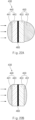
Images











Classifications
-
- F—MECHANICAL ENGINEERING; LIGHTING; HEATING; WEAPONS; BLASTING
- F21—LIGHTING
- F21S—NON-PORTABLE LIGHTING DEVICES; SYSTEMS THEREOF; VEHICLE LIGHTING DEVICES SPECIALLY ADAPTED FOR VEHICLE EXTERIORS
- F21S43/00—Signalling devices specially adapted for vehicle exteriors, e.g. brake lamps, direction indicator lights or reversing lights
- F21S43/20—Signalling devices specially adapted for vehicle exteriors, e.g. brake lamps, direction indicator lights or reversing lights characterised by refractors, transparent cover plates, light guides or filters
- F21S43/26—Refractors, transparent cover plates, light guides or filters not provided in groups F21S43/235 - F21S43/255
-
- F—MECHANICAL ENGINEERING; LIGHTING; HEATING; WEAPONS; BLASTING
- F21—LIGHTING
- F21S—NON-PORTABLE LIGHTING DEVICES; SYSTEMS THEREOF; VEHICLE LIGHTING DEVICES SPECIALLY ADAPTED FOR VEHICLE EXTERIORS
- F21S41/00—Illuminating devices specially adapted for vehicle exteriors, e.g. headlamps
- F21S41/60—Illuminating devices specially adapted for vehicle exteriors, e.g. headlamps characterised by a variable light distribution
- F21S41/68—Illuminating devices specially adapted for vehicle exteriors, e.g. headlamps characterised by a variable light distribution by acting on screens
- F21S41/683—Illuminating devices specially adapted for vehicle exteriors, e.g. headlamps characterised by a variable light distribution by acting on screens by moving screens
-
- F—MECHANICAL ENGINEERING; LIGHTING; HEATING; WEAPONS; BLASTING
- F21—LIGHTING
- F21S—NON-PORTABLE LIGHTING DEVICES; SYSTEMS THEREOF; VEHICLE LIGHTING DEVICES SPECIALLY ADAPTED FOR VEHICLE EXTERIORS
- F21S43/00—Signalling devices specially adapted for vehicle exteriors, e.g. brake lamps, direction indicator lights or reversing lights
- F21S43/20—Signalling devices specially adapted for vehicle exteriors, e.g. brake lamps, direction indicator lights or reversing lights characterised by refractors, transparent cover plates, light guides or filters
- F21S43/2605—Refractors
- F21S43/2621—Refractors characterised by the properties of the light beam shaping surface
- F21S43/26231—Refractors characterised by the properties of the light beam shaping surface collimating, focusing, condensing or projecting beams, e.g. projection lenses or Fresnel lenses
-
- B—PERFORMING OPERATIONS; TRANSPORTING
- B60—VEHICLES IN GENERAL
- B60Q—ARRANGEMENT OF SIGNALLING OR LIGHTING DEVICES, THE MOUNTING OR SUPPORTING THEREOF OR CIRCUITS THEREFOR, FOR VEHICLES IN GENERAL
- B60Q1/00—Arrangement of optical signalling or lighting devices, the mounting or supporting thereof or circuits therefor
- B60Q1/26—Arrangement of optical signalling or lighting devices, the mounting or supporting thereof or circuits therefor the devices being primarily intended to indicate the vehicle, or parts thereof, or to give signals, to other traffic
-
- F—MECHANICAL ENGINEERING; LIGHTING; HEATING; WEAPONS; BLASTING
- F21—LIGHTING
- F21S—NON-PORTABLE LIGHTING DEVICES; SYSTEMS THEREOF; VEHICLE LIGHTING DEVICES SPECIALLY ADAPTED FOR VEHICLE EXTERIORS
- F21S41/00—Illuminating devices specially adapted for vehicle exteriors, e.g. headlamps
- F21S41/20—Illuminating devices specially adapted for vehicle exteriors, e.g. headlamps characterised by refractors, transparent cover plates, light guides or filters
- F21S41/25—Projection lenses
-
- F—MECHANICAL ENGINEERING; LIGHTING; HEATING; WEAPONS; BLASTING
- F21—LIGHTING
- F21S—NON-PORTABLE LIGHTING DEVICES; SYSTEMS THEREOF; VEHICLE LIGHTING DEVICES SPECIALLY ADAPTED FOR VEHICLE EXTERIORS
- F21S41/00—Illuminating devices specially adapted for vehicle exteriors, e.g. headlamps
- F21S41/40—Illuminating devices specially adapted for vehicle exteriors, e.g. headlamps characterised by screens, non-reflecting members, light-shielding members or fixed shades
- F21S41/43—Illuminating devices specially adapted for vehicle exteriors, e.g. headlamps characterised by screens, non-reflecting members, light-shielding members or fixed shades characterised by the shape thereof
-
- F—MECHANICAL ENGINEERING; LIGHTING; HEATING; WEAPONS; BLASTING
- F21—LIGHTING
- F21S—NON-PORTABLE LIGHTING DEVICES; SYSTEMS THEREOF; VEHICLE LIGHTING DEVICES SPECIALLY ADAPTED FOR VEHICLE EXTERIORS
- F21S41/00—Illuminating devices specially adapted for vehicle exteriors, e.g. headlamps
- F21S41/40—Illuminating devices specially adapted for vehicle exteriors, e.g. headlamps characterised by screens, non-reflecting members, light-shielding members or fixed shades
- F21S41/47—Attachment thereof
-
- F—MECHANICAL ENGINEERING; LIGHTING; HEATING; WEAPONS; BLASTING
- F21—LIGHTING
- F21S—NON-PORTABLE LIGHTING DEVICES; SYSTEMS THEREOF; VEHICLE LIGHTING DEVICES SPECIALLY ADAPTED FOR VEHICLE EXTERIORS
- F21S41/00—Illuminating devices specially adapted for vehicle exteriors, e.g. headlamps
- F21S41/60—Illuminating devices specially adapted for vehicle exteriors, e.g. headlamps characterised by a variable light distribution
- F21S41/68—Illuminating devices specially adapted for vehicle exteriors, e.g. headlamps characterised by a variable light distribution by acting on screens
- F21S41/683—Illuminating devices specially adapted for vehicle exteriors, e.g. headlamps characterised by a variable light distribution by acting on screens by moving screens
- F21S41/695—Screens rotating around a vertical axis
-
- F—MECHANICAL ENGINEERING; LIGHTING; HEATING; WEAPONS; BLASTING
- F21—LIGHTING
- F21S—NON-PORTABLE LIGHTING DEVICES; SYSTEMS THEREOF; VEHICLE LIGHTING DEVICES SPECIALLY ADAPTED FOR VEHICLE EXTERIORS
- F21S43/00—Signalling devices specially adapted for vehicle exteriors, e.g. brake lamps, direction indicator lights or reversing lights
- F21S43/20—Signalling devices specially adapted for vehicle exteriors, e.g. brake lamps, direction indicator lights or reversing lights characterised by refractors, transparent cover plates, light guides or filters
- F21S43/255—Filters
-
- B—PERFORMING OPERATIONS; TRANSPORTING
- B60—VEHICLES IN GENERAL
- B60Q—ARRANGEMENT OF SIGNALLING OR LIGHTING DEVICES, THE MOUNTING OR SUPPORTING THEREOF OR CIRCUITS THEREFOR, FOR VEHICLES IN GENERAL
- B60Q2400/00—Special features or arrangements of exterior signal lamps for vehicles
- B60Q2400/50—Projected symbol or information, e.g. onto the road or car body
-
- F—MECHANICAL ENGINEERING; LIGHTING; HEATING; WEAPONS; BLASTING
- F21—LIGHTING
- F21W—INDEXING SCHEME ASSOCIATED WITH SUBCLASSES F21K, F21L, F21S and F21V, RELATING TO USES OR APPLICATIONS OF LIGHTING DEVICES OR SYSTEMS
- F21W2103/00—Exterior vehicle lighting devices for signalling purposes
- F21W2103/60—Projection of signs from lighting devices, e.g. symbols or information being projected onto the road
-
- F—MECHANICAL ENGINEERING; LIGHTING; HEATING; WEAPONS; BLASTING
- F21—LIGHTING
- F21W—INDEXING SCHEME ASSOCIATED WITH SUBCLASSES F21K, F21L, F21S and F21V, RELATING TO USES OR APPLICATIONS OF LIGHTING DEVICES OR SYSTEMS
- F21W2107/00—Use or application of lighting devices on or in particular types of vehicles
- F21W2107/10—Use or application of lighting devices on or in particular types of vehicles for land vehicles
-
- F—MECHANICAL ENGINEERING; LIGHTING; HEATING; WEAPONS; BLASTING
- F21—LIGHTING
- F21Y—INDEXING SCHEME ASSOCIATED WITH SUBCLASSES F21K, F21L, F21S and F21V, RELATING TO THE FORM OR THE KIND OF THE LIGHT SOURCES OR OF THE COLOUR OF THE LIGHT EMITTED
- F21Y2115/00—Light-generating elements of semiconductor light sources
- F21Y2115/10—Light-emitting diodes [LED]
Definitions
- the present disclosure relates to a lamp for a vehicle, and more particularly, to a lamp for a vehicle employing a micro-lens array.
- a micro-lens array projects an image by arranging a plurality of micro lenses.
- the micro lens array in a smaller size shows an image having excellent quality, so the micro-lens array has been widely used in various fields.
- Recently, researches and studies have been performed to reduce the size of a lamp of a vehicle (or a vehicle lamp) by using a micro-lens having a shorter focal length.
- a quantity of light may be reduced with respect to a longer distance pattern, so the uniform pattern may not be ensured. Accordingly, a technology for improving the uniformity of an optical pattern is necessary by minimizing the loss in the quantity of light.
- the vehicle lamp having the micro-lens array irradiates light onto a road surface while being tilted, a resolution and optical performance may be degraded.
- an optical system is mounted to be tilted such that light is tilted and irradiated onto a road surface. In this case, an inner area of the lamp, which is occupied by the optical system, is increased to increase the size of the vehicle lamp.
- a Welcome Ceremony technology is to provide various pieces of information, such as a vehicle state before vehicle driving, to a driver, thereby significantly increasing the convenience and the productivity.
- a welcome light or a puddle lamp which is one example of the welcome ceremony technology, is turned on a side surface of a vehicle to form a beam pattern when the vehicle is unlocked through a smart key. Accordingly, the welcome light or the puddle lamp is a technology to enhance the productivity of the vehicle and to provide information such as a parking position.
- a projection-type optical system equipped with a micro-lens array has been used for a vehicle lamp to display specific information on a road surface, which is similar to the welcome light.
- the convention projection-type optical system is provided to realize only one pattern in a static image form. Accordingly, the conventional projection-type optical system may not realize a dynamic image. According to the related art, when the dynamic image is realized, the visibility may not be ensured or the intuitive understanding of the information may be difficult.
- An aspect of the present disclosure provides a vehicle lamp in which a lens array is separately designed for each partition region such that an optical system having the optimal orientation angle and the optimal luminous intensity are realized, thereby improving the light uniformity of the pattern of the beam irradiated onto the road surface.
- a lamp for a vehicle includes a light source device to generate and output light and a lens array provided in front of the light source device.
- the lens array includes a first lens device including a plurality of first micro-lenses to receive light incident thereto from the light source device, and a second lens device including a plurality of second micro-lenses provided to irradiate light, which is incident thereto from the first lens device, on the road surface to form a specific beam pattern.
- the beam pattern is divided into a plurality of pattern regions depending on a distance from the lamp for the vehicle.
- the lens array is divided into a plurality of partition regions corresponding to the plurality of pattern regions, respectively, and provided to increase a focal length of the second micro-lens provided in a partition region corresponding to a pattern region, as the pattern region is positioned at a distance longer from the lamp for the vehicle
- the lamp may further include a shielding part interposed between the first lens device and the second lens device to shield a portion of the light from the first lens device to the second lens device, such that a specific beam pattern is formed on the road surface.
- the shielding part may include a plurality of unit masks provided to correspond to the plurality of second micro-lenses, respectively, and having a masking pattern for forming the beam pattern.
- the unit mask may include a shielding region provided to shield light, and a light transmitting region provided to transmit light and having a shape corresponding to the masking pattern.
- the lamp may be provided to decrease a curvature of a second micro-lens, which is provided in a partition region corresponding to a pattern region, as the pattern region is positioned at a distance longer from the lamp for the vehicle.
- the lamp may be provided to increase a thickness of a second micro-lens, which is provided in a partition region corresponding to a pattern region, as the pattern region is positioned at a distance longer from the lamp for the vehicle.
- the first micro-lens and the second micro-lenses provided in the same partition region may be formed to be equal to each other in width in a vertical direction, and the width may be within a machining error range.
- the lamp may be provided to increase a curvature of a first micro-lens, which is provided in a partition region corresponding to a pattern region, as the pattern region is positioned at a distance longer from the lamp for the vehicle.
- the lens array is formed such that the second optical axis is tilted about the first optical axis to extend toward the road surface.
- the size of an acute angle of angles, which are formed between the first optical axis and the second optical axis, is reduced in a partition region corresponding to a pattern region, as the pattern region is positioned a distance longer from the lamp for the vehicle.
- the second lens device may further include a second light transmitting body, which includes the second micro-lens formed on a surface facing a direction opposite to a direction facing the light source device, and provided to transmit the light.
- the second micro-lenses may be provided in the second light transmitting body, such that a thickness direction of the second micro-lenses is titled about the direction of the first optical axis.
- the plurality of partition regions may be placed in quadrant plates obtained by dividing the lens array about the optical axis of the light source device.
- the plurality of partition regions may be provided to form pattern regions at distances which are gradually longer from the lamp for the vehicle, counterclockwise from the partition region corresponding to a pattern region at a distance shortest from the lamp for the vehicle.
- the lamp for the vehicle may further include a driving shield unit.
- the driving shield unit may include a rotating shield interposed between the light source device and the lens array, having an opening formed through the rotating shield having a size corresponding to one of the plurality of partition regions and provided to be rotatable.
- the rotating shield may be formed in the shape of a disk perpendicular to the optical axis of the light source device.
- the driving shield unit may include a driving motor to provide driving force, and a transfer gear connected to a driving shaft of the driving motor and engaged with a gear formed at an edge of the rotating shield.
- the driving shield unit may be provided to transform a lamp image of the beam pattern, by changing the position of the opening, as the rotating shield rotates.
- a lamp 100, 200, 300, or 400 for a vehicle which is a vehicle lamp using a micro-lens array, may be, for example, a guide lamp to realize a pattern image having a specific shape on a road surface 2 by projecting light to the road surface 2 which is in the vicinity of a vehicle 1.
- the vehicle lamp 100, 200, 300, or 400 may be a reverse guide lamp, a welcome guide lamp, and a turn signal guide lamp which is lit together with a reverse lamp.
- the vehicle lamp 100, 200, 300, or 400 according to the present disclosure is the reverse guide lamp (see FIG. 1 ) or a turn signal lamp (see FIG. 15 ).
- various vehicle lamps 100, 200, 300, or 400 may be employed without limitation, as long as the vehicle lamp irradiates light in a specific pattern on the road surface.
- the vehicle lamp 100, 200, 300, or 400 irradiates light onto the road surface while being frequently titled. Accordingly, the difference in brightness may be made between a longer distance pattern region, which is positioned at a longer distance from the vehicle lamp, and a shorter distance pattern region which is positioned at a shorter distance from the vehicle lamp. In other words, the brightness of the longer distance pattern region becomes darker than the brightness of the shorter distance pattern region, so the light uniformity may be degraded.
- the present invention suggests a technology of solving the above problem.
- FIGS. 1 to 8C illustrate a first embodiment of the present disclosure.
- FIG. 1 is a view illustrating that a vehicle lamp is mounted in a vehicle, according to a first embodiment of the present disclosure.
- FIG. 2 is a perspective view illustrating a vehicle lamp, according to the first embodiment of the present disclosure.
- FIG. 3 is a cross-sectional view illustrating a vehicle lamp, according to the first embodiment of the present disclosure.
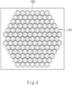
- FIG. 4 is a front view illustrating a lens array, according to the first embodiment of the present disclosure.
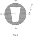
- FIG. 5 is a view illustrating a unit mask of a shielding part, according to the first embodiment of the present disclosure.
- FIG. 1 is a view illustrating that a vehicle lamp is mounted in a vehicle, according to a first embodiment of the present disclosure.
- FIG. 2 is a perspective view illustrating a vehicle lamp, according to the first embodiment of the present disclosure.
- FIG. 3 is a cross-sectional view illustrating a vehicle lamp, according to the first embodiment of
- FIG. 6 is a cross-sectional view illustrating a vehicle lamp, according to the first embodiment of the present disclosure, which is an enlarged view illustrating a part of FIG. 3 .
- FIG. 7 is a cross-sectional view illustrating a vehicle lamp, according to a modification of the first embodiment of the present disclosure.
- FIG. 8A is a view illustrating the central region of a lens array, that is, a unit mask disposed in a first region, according to the present disclosure.
- FIG. 8B is a view illustrating a unit mask interposed between the central region of a lens array and an edge region of the lens array, according to the present disclosure.
- FIG. 8C is a view illustrating a unit mask disposed at an edge region of a lens array, according to the present disclosure.
- the vehicle lamp 100 includes a light source device 110 and a lens array 130.
- the vehicle lamp 100 may further include a shielding part 160.
- the light source device 110 is provided to generate and irradiate light.
- the lens array 130 is provided in front of the light source device 110 to output light, which is incident to the lens array 130 from the light source device 110, forward.
- the light source device 110 may be provided to irradiate light toward the road surface 2.
- the light source device 110 may include a light source 111 and a collimator 113.
- the light source 111 may be, but is not limited to, a light emitting diode (hereinafter, an LED).
- the collimator 113 may convert light emitted from the light source 111 into light parallel to an optical axis and may allow the light to be incident into a first lens device 140.
- the lens array 130 includes the first lens device 140 and a second lens device 150.
- the first lens device 140 includes a plurality of first micro-lenses 141 to receive light incident thereto from the light source device 110.
- the second lens device 150 includes a plurality of second micro-lenses 151 provided to output the light incident from the first lens device 140.
- the first micro-lenses 141 may include incident surfaces which are convex toward the light source device 110, and the incident surfaces of the first micro-lenses 141 may form the whole incident surface of the first lens device 140.
- the second micro-lenses 151 may include output surfaces which are convex toward the road surface 2, and the output surfaces of the second micro-lenses 151 may form the whole output surface of the second lens device 150.
- the shapes of the first micro-lens 141 and the second micro-lens 151 are not limited to the above shapes.
- the first lens device 140 may further include a first light transmitting body 143.
- the first light transmitting body 143 has a surface facing the light source device 110, and the first micro-lens 141 is formed on the surface.
- the first light transmitting body 143 may include a material for transmitting light.
- the second lens device 150 may further include a second light transmitting body 153.
- the second micro-lens 151 is formed on a surface, which faces a direction opposite to a direction facing the first light transmitting body 143, to transmit light.
- the second light transmitting body 153 may be provided to face the first light transmitting body 143 while the shielding part 160 is interposed between the first light transmitting body 143 and the second light transmitting body 153.
- the first light transmitting body 143 and the second light transmitting body 153 may serve as bodies for integrally forming the first lens device 140 and the second lens device 150. However, the present disclosure is not limited thereto. When the first lens device 140 and the second lens device 150 are not integrally formed, at least one of the first light transmitting body 143 and the second light transmitting body 153 may be omitted.
- the size of at least a portion of the first micro-lens 141 is smaller than the size of the second micro-lens 151, which is provided corresponding to the at least a portion of the first micro-lens 141, in a vertical direction.
- the central region, through which the optical axis of the light source device 110 passes, of a partial region of the lens array 130 is referred to a first region 'I', and a region, which is provided around the first region 'I', of a remaining region of the lens array 130 is referred to as a second region 'II'.
- the size of the first micro-lens 141, which is provided in the second region 'II' may be smaller than the size of the second micro-lens 151 which is provided in the second region 'II' in the vertical direction.
- the sizes of the first micro-lens 141 and the second micro-lens 151 in the vertical direction may be formed to be equal to each other or to be approximate to each other, in the first region 'I' which is the central region representing the highest value in the brightness of light irradiated from the light source device 110, when viewed from an incident side of the first lens device 140.
- the size of the first micro-lens 141 may be formed to be smaller than the size of the second micro-lens 151 in the vertical direction, in the second region 'II' serving as a peripheral region of the central region, which represents the lower value in the brightness of light irradiated from the light source device 110, when viewed from the incident side of the first lens device 140.
- the size of the size of the second micro-lens 151 may be twice larger than the size of the first micro-lens 141 in the vertical direction.
- the present disclosure is not limited thereto.
- the size of the second micro-lens 151 may be at least three times larger than the size of the first micro-lens 141 in the vertical direction.
- the curvature of the lens may be increased when the size of the lens in the vertical direction is reduced, and a quantity of light incident through the lens may be increased, when the curvature of the lens may be increased.
- the first micro-lens 141 provided in the second region 'II' may be formed to have a smaller size in the vertical direction. Accordingly, a quantity of light incident through the first micro-lens 141 may be increased, in the second region 'II' showing the lower value in the luminous intensity of the light irradiated from the light source device 110
- the uniformity of a quantity of light incident to the whole region of the first lens device 140 may be improved. Accordingly, the uniformity of a beam pattern formed on the road surface 2 by the lens array 130 may be improved. Therefore, according to the present disclosure, the loss in the quantity of light is minimized. Accordingly, the uniformity of the beam pattern formed on the road surface 2 may be increased without employing the additional light source 111.
- the curvature of the first micro-lens 141, which is provided in the second region 'II' may be larger than the curvature of the first micro-lens 141 which is provided in the first region 'I' in the vertical direction.
- the first micro-lens 141 in the second region 'II' may be formed to have the radius of curvature smaller than the radius of curvature of the first micro-lens 141 in the first region 'I'. Accordingly, as the quantity of light incident through the first micro-lens 141 in the second region 'II' is increased, the loss in the quantity of light may be minimized. Accordingly, the uniformity of the quantity of the light incident into the whole region of the first lens device 140 may be improved.
- the plurality of first micro-lenses 141 in the second region 'II' may be formed to be gradually reduced in size in the vertical direction, as the plurality of first micro-lenses 141 in the second region 'II' becomes away from the first region 'I'.
- light radiated from the light source 111 and passing through the collimator 113 shows the highest luminous intensity in the central region of the first lens device 140, and shows the luminous intensity, which is gradually reduced away from the central region.
- the plurality of first micro-lenses 141 provided in the second region 'II' may be formed to have the size reduced in the vertical direction away from the central region. Accordingly, a quantity of light incident through the first micro-lenses 141 provided in the second region 'II' may be increased.
- the shielding part 160 may be interposed between the first lens device 140 and the second lens device 150 to shield a portion of light incident from the first lens device 140 to the second lens device 150, such that a specific beam pattern may be formed on the road surface 2.
- the shielding part 160 may include a unit mask 161.
- a plurality of unit masks 161 may be provided to correspond to a plurality of second micro-lenses 151, respectively.
- the unit mask 161 may have a masking pattern for forming a beam pattern.
- the unit masks 161 may be provided to correspond to the second micro-lenses 151, which are disposed at an output side of the lens array 130, respectively.
- the unit mask 161 may include a shielding region 162 provided to shield light, and a light transmitting region 163 provided to transmit light and having a shape corresponding to a masking pattern.
- the image of the beam pattern projected on the road surface 2 may be varied depending on the shape of the light transmitting region 163, that is, the shape of the masking pattern
- the unit mask 161 may be provided in the form of a plate and may form a specific beam pattern, as the light is masked in the shielding region 162.
- a direction, in which the beam pattern is away from the vehicle lamp 100 is defined as a longer distance direction, and a direction opposite to the longer distance direction is defined as a shorter distance direction.
- a plurality of first micro-lenses 141 may be provided to correspond to one second micro-lens 151 in the second region 'II'.
- the shielding region 162 may include a longer distance edge 162b provided to make contact with an end portion of the light transmitting region 163 while forming an end line in the longer distance direction of the beam pattern, and a shorter distance edge 162a provided to face the longer distance edge 162b while forming an end line in a shorter distance direction of the beam pattern.
- the longer distance edge 162b may make contact with an upper end of the light transmitting region 163, and the shorter distance edge 162a may make contact with a lower end of the light transmitting region 163.
- a focus F of the first micro-lens 141 which forms a beam pattern at the longest distance, of the plurality of first micro-lenses 141 corresponding to one second micro-lens 151 may be formed at a position corresponding to the longer distance edge 162b.
- the first micro-lens 141 which is placed at an upper portion of the first micro-lenses 141 in the vertical direction, may form a beam pattern at a longer distance.
- the focus F of the first micro-lens 141 placed at the upper portion may be positioned to be adjacent to the longer distance edge 162b.
- the focus F of the first micro-lens 141 is positioned at the longer distance edge 162b, a point showing the maximum luminous intensity of the first micro-lens 141 is positioned at the longer distance edge 162b. Accordingly, as the brightness of the beam pattern is increased at the longer distance region, the uniformity of the beam pattern may be improved.
- a point showing the maximum luminous intensity of the first micro-lens 141 is positioned even at the shorter distance edge 162a.
- a pattern at a longer distance and a pattern at a shorter distance may be not uniform.
- a curvature of the first micro-lens 141, which forms a beam pattern at the longest distance, of the first micro-lenses 141 corresponding to the one second micro-lenses 151, in the vertical direction may be formed to be greater than a curvature of remaining first micro-lenses 141 of the first micro-lenses 141 corresponding to the one second micro-lenses 151 in the vertical direction.
- the radius of curvature of the first micro-lens 141 which irradiates light to the shorter distance region, is more increased, a light concentration rate may be lowered. Therefore, as the brightness of the shorter distance region and the brightness of the longer distance region are uniform on the beam pattern, the uniformity of the pattern may be improved.
- the focus F of the first micro-lens 141 which forms the beam pattern in the longest distance direction, may be provided to be positioned inside the light transmitting region 163.
- the focus F of the remaining first micro-lens 141 other than the first micro-lens 141 forming the beam pattern in the longest distance direction may be provided to be positioned at spaced points in front or back of the light transmitting region 163
- the brightness of the longer distance region and the brightness of the shorter distance region are uniform on the beam pattern, thereby improving the uniformity of the pattern.
- FIG. 8A is a view illustrating a unit mask 161 disposed in the central region, that is, the first region "I", of the lens array 130, according to the present disclosure.
- FIG. 8C is a view illustrating a unit mask 161 disposed at an edge region of the lens array 130, according to the present disclosure.
- FIG. 8B is a view illustrating a unit mask 161 disposed between the central region and the edge region of the lens array 130, according to the present disclosure.
- a plurality of unit masks 161 may be formed to include a light transmitting region 163 having a size which is gradually increased farther away from the central portion, through which an optical axis passes, of the light source device 110.
- light incident to the first lens device 140 through the collimator 113 may have the highest luminous intensity at the central portion of the first lens device 140.
- the brightness of the beam pattern may be increased.
- the unit mask 161 may be formed to include the light transmitting region 163 having a size increased toward the edge of the lens array 130 from the central portion of the lens array 130, thereby improving light uniformity of a beam pattern irradiated onto the road surface 2.
- unit masks 161 which are adjacent to each other toward the edge of the lens array 130 from the central portion of the lens array 130, may be formed to include light transmitting regions 163 having the sizes making the difference within a specific size (for example, about 1 mm). Accordingly, since the quantity of light is not sharply changed between pattern regions corresponding to the unit masks 161 adjacent to each other, the pattern disconnection resulting from the change in the quantity of light may be prevented in advance.
- a direction, in which the beam pattern is away from the vehicle lamp 100 is defined as a longer distance direction, and a direction opposite to the longer distance direction is defined as a shorter distance direction.
- the shielding region 162 may include a longer distance edge 162b provided to make contact with an end portion of the light transmitting region 163 while forming an end line in the longer distance direction of the beam pattern, and a shorter distance edge 162a provided to face the longer distance edge 162b while forming an end line in a shorter distance direction of the beam pattern.
- a plurality of unit masks 161 may be formed to include a light transmitting region 163 having a size which is gradually increased, by increasing the distance between the longer distance edge 162b and the shorter distance edge 162a, farther away from the central portion, through which an optical axis passes, of the light source device 110.
- the shorter distance edge 162a formed in each of the plurality of unit masks 161 may have an equal width in a left-right direction.
- the size of the light transmitting region 163 may be adjusted by making the position and the size of the shorter distance edge 162a uniform and changing the position and the size of the longer distance edge 162b, on each unit mask 161.
- the ratio of the longer distance edge 162b to the shorter distance edge 162a in the shielding region 162 may be greater than the ratio of the end line provided in the longer distance direction to the end line provided in the shorter distance direction.
- the width of the longer distance edge 162b in the left-right direction may be greater than the width of the shorter distance edge 162a, which faces the longer distance edge 162b, in the left-right direction.
- the light transmitting region 163 may be formed in the shape of a trapezoid.
- the uniformity of the quantity of light incident to the whole region of the first lens device may be improved. Accordingly, the uniformity of the beam pattern formed on the road surface may be improved by the lens array.
- the loss in the quantity of light is minimized. Accordingly, the uniformity of the beam pattern formed on the road surface may be increased without employing the additional light source.
- FIGS. 9 to 14 illustrate a second embodiment of the present disclosure.
- FIG. 9 is a view schematically illustrating a vehicle lamp, according to a second embodiment of the present disclosure.
- FIG. 10 is a view schematically illustrating a vehicle lamp, according to a comparative example of the present disclosure.
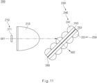
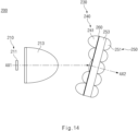
- FIG. 11 is a side view illustrating a vehicle lamp, according to a second embodiment of the present disclosure.
- FIG. 12 is a side view illustrating a vehicle lamp, according to a modification of the second embodiment of the present disclosure.
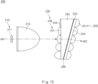
- FIG. 13 is a side view illustrating a vehicle lamp according to another modification of the second embodiment of the present disclosure.
- FIG. 14 is a side view illustrating a vehicle lamp, according to still another modification of the second embodiment of the present disclosure.
- the vehicle lamp 200 includes a light source device 210 and a lens array 230.
- the vehicle lamp 200 may further include a shielding part 260.
- the light source device 210 is provided to generate and irradiate light.
- the lens array 230 is provided in front of the light source device 210 to output light, which is incident to the lens array 230 from the light source device 210, forward.
- the light source device 210 may be provided to irradiate light toward the road surface 2.
- the light source device 210 may include a light source 211 and a collimator 213.
- the light source 211 may be, but is not limited to, a light emitting diode (hereinafter, an LED).
- the collimator 213 may convert light emitted from the light source 211 into light parallel to an optical axis and may allow the light to be incident into a first lens device 240.
- the lens array 230 includes the first lens device 240 and a second lens device 250.
- the first lens device 240 includes a plurality of first micro-lenses 241 to receive light incident thereto from the light source device 210.
- the second lens device 250 includes a plurality of second micro-lenses 251 provided to output the light incident from the first lens device 240.
- the first micro-lenses 241 may include incident surfaces which are convex toward the light source device 210, and the incident surfaces of the first micro-lenses 241 may form the whole incident surface of the first lens device 240.
- the second micro-lenses 251 may include output surfaces 254 which are convex toward the road surface 2, and the output surfaces 254 of the second micro-lenses 251 may form the whole output surface 254 of the second lens device 250.
- the shapes of the first m icro-lens 241 and the second micro-lens 251 are not limited to the above shapes.
- the first lens device 240 may further include a first light transmitting body 243.
- the first light transmitting body 243 has a surface facing the light source device 210, and the first micro-lens 241 is formed on the surface.
- the first light transmitting body 143 may include a material for transmitting light.
- the second lens device 250 may further include a second light transmitting body 253.
- the second micro-lens 251 is formed on a surface, which faces a direction opposite to a direction facing the first light transmitting body 243, to transmit light.
- a second light transmitting body 253 may be provided to face the first light transmitting body 243 while the shielding part 260 is interposed between the first light transmitting body 243 and the second light transmitting body 253.
- the first light transmitting body 243 and the second light transmitting body 253 may serve as bodies for integrally forming the first lens device 240 and the second lens device 250. However, the present disclosure is not limited thereto. When the first lens device 240 and the second lens device 250 are not integrally formed, at least one of the first light transmitting body 243 and the second light transmitting body 253 may be omitted.
- the lens array 230 is formed such that the second optical axis AX2 is tilted toward the road surface 2 about the first optical axis AX1.
- the first optical axis AX1 which is an optical axis of light incident toward the first lens device 240, may be an optical axis of light output from the light source device 210.
- the lens array 230 may be formed such that the first axis AX1 serving as an optical axis of the light incident toward the first lens device 240 is formed at an angle different from an angle of the second optical axis AX2 serving as the optical axis of the light output from the second lens device 250.
- the first optical axis AX1 may extend in parallel to the road surface 2, that is, in a longitudinal direction of the vehicle 1.
- the second optical axis AX2 extends toward the road surface 2 from the second lens device 250, such that the second optical axis AX2 is titled about the first optical axis AX1.
- the present disclosure when light is irradiated and tilted about the road surface 2 through a vehicle lamp 200, an entire portion of the light source device 210 and the lens array 230 are not mounted to be tilted toward the road surface 2, but only the second optical axis AX2 of the second lens device 250 is formed to be tilted such that a beam pattern is formed on the road surface 2. In this case, since the size M1 of the lens array 230 is reduced, the vehicle lamp 200 in a smaller size may be realized.
- FIG. 10 is a view illustrating a comparative example of the present disclosure.
- the reference numerals of the comparative example of the present disclosure are the same as reference numerals of FIG. 9 according to the present disclosure.
- the size M2 of the vehicle lamp 200 when the entire portion of the light source device 210 and the lens array 230 are mounted to be tilted toward the road surface 2, the size M2 of the vehicle lamp 200, particularly, the height of the vehicle lamp 200 in the vertical direction is increased. Accordingly, the space occupied by the vehicle lamp 200 inside the vehicle 1 may be widened. Meanwhile, as illustrated in FIG.
- the vehicle lamp 200 in a smaller size may be realized. Accordingly, the space occupied by the vehicle lamp 200 may be reduced.
- various manners may be, without limitation, employed to form the second optical axis AX2 of the second lens device 250, such that the second optical axis AX2 is tilted about the first optical axis AX1.
- the lens array 230 is formed to be titled about a plane perpendicular to the first optical axis AX1, such that the second optical axis AX2 forms a specific angle about the first axis AX1.
- all of the first micro-lens 241, the first light transmitting body 243, the shielding part 260, the second light transmitting body 253, and the second micro-lens 251 may be placed to be tilted about the first optical axis AX1.
- the optical axis AX2 provide in the second lens device 250 may extend in a direction tilted about the first optical axis AX1.
- incident light may have various incident angles throughout the entire region of the first lens device 240.
- the difference in incident angle may be made between an upper portion of the first lens device 240 and a lower portion of the first lens device 240.
- a quantity of light and a resolution may be varied throughout the entire region of the lens array 230.
- the second optical axis AX2 is tilted about the first optical axis AX1 while extending toward the road surface 2.
- optical performance may be complemented by changing the form of the shielding part 260, the second light transmitting body 253, and the second micro-lens 251.
- the shielding part 260 may be interposed between the first lens device 240 and the second lens device 250 to shield a portion of light incident from the first lens device 240 toward the second lens device 250, such that a specific beam pattern may be formed on the road surface 2.
- the shielding part 260 may further include a unit mask 261.
- a plurality of unit masks 261 may be provided to correspond to a plurality of second micro-lenses 251, respectively, and a masking pattern may be formed to form a beam pattern.
- the plurality of unit masks 261 may be placed to be away from the second micro-lenses 251 toward the lower portion of the lens array 230.
- each of the second micro-lenses 251 may be positioned on each unit mask 261.
- the focus of the second micro-lenses 151 may be elongated toward the lower portion of the lens array 230.
- the focal length of the second micro-lenses 151 is increased toward the lower portion of the lens array 230. Accordingly, as the lens array 230 is titled, the difference in resolution between regions may be corrected.
- the radius of curvature of the plurality of second micro-lenses 151 may be formed to be gradually increased toward the lower portion of the lens array 230.
- the focal length of the second micro-lenses 151 may be increased toward the lower portion of the lens array 230. Accordingly, as the lens array 230 is tilted, the difference in resolution between regions may be corrected.
- an incident surface 244 which is a surface, which faces the light source device 210 of the first light transmitting body 243, may be formed to be perpendicular to the first optical axis AX1.
- an output surface 254, which is a surface, which faces a direction opposite to a direction facing the light source device 210, of the second light transmitting body 253 may be formed to be tilted about the incident surface 244, such that the output surface 254 is closer to the incident surface 244 toward a lower portion of the lens array 230.
- the shielding part 260 may be provided in parallel to the output surface 254
- the second light transmitting body 253 and the assembly with the second light transmitting body 253 have the shape of a trapezoid having a size gradually reduced downward. Accordingly, the second optical axis AX2 of the second micro-lenses 251 may be tilted about the first axis AX1 without tilting the lens array 230. In other words, since the first lens device 240 is not tilted about the first axis AX1, the light loss resulting from the difference between incident angles may be minimized.
- the radius of curvature of the plurality of first micro-lenses 241 may be formed to be gradually reduced downward.
- the shielding part 260 and the second micro-lenses 251 are tilted about the first axis AX1. Accordingly, the distance between the first micro-lens 241 and the shielding part 260 may be gradually reduced downward. In other words, the difference in distance between the first micro-lens 241 and the shielding part 260 is varied throughout the entire portion of the lens array 230 to cause the difference in quantity of light. Accordingly, the radius of curvature of the first micro-lens 241 may be formed to be gradually reduced downward to correct the difference in quantity of light caused by the difference in distance between the first micro-lens 241 and the shielding part 260
- the shielding part 260 may be provided to be closer to the first micro-lens 241, rather than the second micro-lenses 251.
- the shielding part 260 may be directly attached to the first micro-lens 241, the position of the shielding part 260 is not limited thereto.
- the shielding part 260 may be provided to be adjacent to the first micro-lens 241 or to make close contact with the first micro-lens 241, the focal length of the second micro-lenses 251 is increased throughout the entire portion of the lens array 230 to correct the resolution.
- the plurality of first micro-lenses 241 may have a radius of curvature gradually reduced, farther away from the central portion, through which the first optical axis AX1 passes, when viewed the lens array 230.
- the light loss may be caused. Accordingly, the difference in luminous intensity may be made between beam patterns formed on the road surface 2.
- the radius of curvature of the plurality of first micro-lenses 241 is away from the central portion, the radius of curvature of the first micro-lenses 241 is gradually reduced. Accordingly, a quantity of light is increased at an outer region of the first lens device 240 to correct the light loss. Accordingly, the uniformity of the beam pattern formed on the road surface 2 may be improved.
- the vehicle lamp may minimize the size of the lens array, even through a lamp which irradiates light on a road surface and titles the light about the road surface. Accordingly, the vehicle lamp in a smaller size may be realized.
- FIGS. 15 to 18 illustrate a third embodiment of the present disclosure.
- FIG. 15 is an exploded perspective view of a vehicle lamp, according to a third embodiment of the present disclosure.
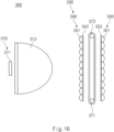
- FIG. 16 is a side view of FIG. 15 , which illustrates a vehicle lamp according to the third embodiment of the present disclosure.
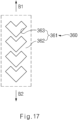
- FIG. 17 is a view illustrating a unit mask formed in a shielding body of FIG. 16 .
- FIGS. 18A to 18D illustrate beam patterns projected to a road surface.
- the vehicle lamp 300 includes a light source device 310 and a lens array 330.
- the vehicle lamp 300 may further include a shielding part 360.
- the light source device 310 is provided to generate and irradiate light.
- the lens array 330 is provided in front of the light source device 310 to output light, which is incident to the lens array 330 from the light source device 310, forward.
- the light source device 310 may be provided to irradiate light toward the road surface 2.
- the light source device 310 may include a light source 311 and a collimator 313.
- the light source 311 may be, but is not limited to, a light emitting diode (hereinafter, an LED).
- the collimator 313 may convert light emitted from the light source 311 into light parallel to an optical axis and may allow the light to be incident to the first lens device 340.
- the lens array 330 includes a first lens device 340 and a second lens device 350.
- the first lens device 340 includes a plurality of first micro-lenses 341 to receive light incident thereto from the light source device 310.
- the second lens device 350 includes a plurality of second micro-lenses 351 provided to output the light incident from the first lens device 340.
- the first micro-lenses 341 may include incident surfaces which are convex toward the light source device 310, and the incident surfaces of the first micro-lenses 341 may form the whole incident surface of the first lens device 340.
- the second micro-lenses 351 may include output surfaces which are convex toward the road surface 2, and the output surfaces of the second micro-lenses 351 may form the whole output surface of the second lens device 350.
- the shapes of the first micro-lens 341 and the second micro-lens 351 are not limited to the above shapes.
- the first lens device 340 may further include a first light transmitting body 343.
- the first light transmitting body 343 has a surface facing the light source device 310, and the first micro-lens 341 is formed on the surface.
- the first light transmitting body 143 may include a material for transmitting light.
- the second lens device 350 may further include a second light transmitting body 353.
- the second micro-lenses 351 is formed on a surface, which faces a direction opposite to a direction facing the first light transmitting body 343, to transmit light.
- the second light transmitting body 353 may be provided to face the first light transmitting body 343 while the shielding part 360 is interposed between the first light transmitting body 343 and the second light transmitting body 353.
- the first light transmitting body 343 and the second light transmitting body 353 may serve as bodies for integrally forming the first lens device 340 and the second lens device 350. However, the present disclosure is not limited thereto. When the first lens device 340 and the second lens device 350 are not integrally formed, at least one of the first light transmitting body 343 and the second light transmitting body 353 may be omitted.
- the shielding part 360 may be interposed between the first lens device 340 and the second lens device 350 to shield a portion of light incident from the first lens device 340 to the second lens device 350, such that a specific beam pattern may be formed on the road surface 2.
- the shielding part 360 may include a unit mask 361.
- a plurality of unit masks 361 may be provided to correspond to a plurality of second micro-lenses 351, respectively.
- the unit mask 161 may have a masking pattern for forming a beam pattern.
- the unit masks 361 may be provided to correspond to the second micro-lenses 351, which are disposed at an output side of the lens array 330, respectively.
- the unit mask 361 may include a shielding region 362 provided to shield light, and a light transmitting region 363 provided to transmit light and having a shape corresponding to a masking pattern.
- the image of the beam pattern projected on the road surface 2 may be varied depending on the shape of the light transmitting region 363, that is, the shape of the masking pattern
- the unit mask 361 may be provided in the form of a plate and may form a specific beam pattern, as the light is masked in the shielding region 362.
- the shielding part 360 may be provided to be movable to change a lamp image of the beam pattern formed on the road surface 2.
- a masking pattern for determining the image of the beam pattern to be projected on the road surface 2 is formed in a shielding body 360a of the shielding part 360. Accordingly, when light is irradiated from the vehicle lamp 300 to the road surface 2, and when the shielding body 360a is moved, the image of the beam pattern may be changed. Accordingly, the beam pattern may be changed to a dynamic image.
- the shielding body 360a is provided to be movable, the shielding part 360 may make a beam pattern, which is formed when the vehicle lamp 300 is turned on, different whenever the vehicle lamp 300 is turned on.
- the beam pattern formed on the road surface 2 is realized in the form of a dynamic image, thereby producing an effect of changing the attention of a counterpart driver, such that visibility is improved.
- the beam pattern is realized in the form of a dynamic image, thereby allowing a counterpart driver or a person around the vehicle 1 to intuitively acquire information on a forward direction of the vehicle 1, when the information on the forward direction of the vehicle 1 is notified to the counterpart driver or the person around the vehicle 1.
- the vehicle lamp 300 may further include a driving device 370.
- the driving device 370 may provide driving force such that the shielding part 360 is movable.
- the display device 370 may include a pair of rollers 371 and 373 and an actuator 375.
- the pair of rollers 371 and 373 may be spaced apart from each other in the vertical direction, and may have a portion of outer surfaces thereof provided to make close contact with the shielding body 360a.
- the pair of rollers 371 and 373 may be provided in parallel to each other and may be provided at an upper end portion and a lower end portion of the shielding body 360a, respectively.
- the arrangement of the rollers 371 and 373 is not limited thereto.
- the shielding body 360a may be formed in the form of a plate having a wider width, and may include a soft material. Accordingly, the upper end portion and the lower end portion of the shielding body 360a may be hung on the pair of rollers 371 and 373. When the rollers 371 and 373 are rotated, the shielding body 360a may be provided to move. In this case, the unit mask 361 formed in the shielding body 360a moves such that the image of the beam pattern is changed.
- the actuator 375 may be connected to a rotating shaft 372 of any one of the pair of rollers 371 and 373 to rotate the rollers 371 and 373.
- the shielding body 360a rotates together with the rollers 371 and 373.
- the actuator 375 may be automatically driven by a control unit.
- the display device 370 may be provided to change the rotating speed of the rollers 371 and 373. Accordingly, the moving speed of the shielding body 360a may be changed.
- the display device 370 may adjust the speed of changing the dynamic image of the beam pattern by adjusting a revolution per minute of the actuator 375.
- the display device 370 is stopped or rapidly driven at a specific speed or more, to realize a constant static
- a masking pattern formed on each of the plurality of unit masks 361 may have the same image.
- the light transmitting regions 363 of the plurality of unit masks 361 may be formed to have the same shape. Accordingly, the focuses of all second micro-lenses 351 may be provided to be paired with the unit masks 361 formed to have the same masking pattern image.
- the plurality of second micro-lenses 351 may have the same curvature.
- the focus of the second micro-lenses 351 may be provided to be positioned on the shielding part 360.
- the shielding part 360 may be provided in such a manner than the masking pattern of the unit mask 361 positioned on a focus of each second micro-lens 351 may constantly have the same shape at any time point, when the actuator 375 is driven.
- beam patterns transmitted through the second micro-lenses 351 at any moment may be realized to have the same image.
- the shielding part 360 may include a rear surface portion provided to face the first micro-lens 341 and a front surface portion provided to face the second micro-lenses 351, when viewed based on the rollers 371 and 373 at any time point.
- the unit mask 361 positioned on the focus of the second micro-lenses 351 may be provided to be positioned on the front surface portion.
- FIG. 17 illustrates a unit mask 361 formed in the shielding body 360a
- FIGS. 18A to 18D illustrate a beam pattern projected onto the road surface 2 through one second micro-lens 351.
- the unit mask 361 may move in the vertical direction while the shielding body 360a is moving, as illustrated in FIG. 17 (see directions B1 and B2).
- the beam pattern projected on the road surface 2 may be varied over time.
- the beam patterns realized through one second micro-lens 351 over time may be sequentially varied in sequence of FIG. 18A, FIG. 18B, FIG. 18C, and FIG. 18D .
- the shape of the masking pattern of the unit mask 361 or the shape of the changed image according to the present disclosure is not limited to the embodiment illustrated.
- the beam pattern formed on the road surface 2 is realized in the form of a dynamic image, thereby producing an effect of changing the attention of a counterpart driver, such that visibility is improved.
- the beam pattern is realized in the form of a dynamic image, thereby allowing a counterpart driver or a person around the vehicle to intuitively acquire information on a forward direction of the vehicle, when the information on the forward direction of the vehicle is notified to the counterpart driver or the person around the vehicle.
- FIGS. 19 to 28 illustrate a fourth embodiment of the present disclosure.
- FIG. 19 is a view illustrating that a vehicle lamp is mounted in a vehicle, according to a fourth embodiment of the present disclosure.
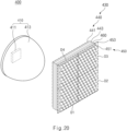
- FIG. 20 is a perspective view illustrating a vehicle lamp, according to the fourth embodiment of the present disclosure.
- FIG. 21 is a cross-sectional view illustrating a vehicle lamp, according to the fourth embodiment of the present disclosure.
- FIG. 22A illustrates a portion of a first partition region of a lens array, according to the fourth embodiment of the present disclosure.
- FIG. 22B illustrates a portion a fourth partition region of a lens array, according to the fourth embodiment of the present disclosure.
- FIG. 22A illustrates a portion of a first partition region of a lens array, according to the fourth embodiment of the present disclosure.
- FIG. 22B illustrates a portion a fourth partition region of a lens array, according to the fourth embodiment of the present disclosure.
- FIG. 23 is a cross-sectional view illustrating a vehicle lamp, according to a modification of the fourth embodiment of the present disclosure.
- FIG. 24A is an enlarged cross-sectional view of a first partition region of a lens array, according to the fourth embodiment of the present disclosure.
- FIG. 24B is an enlarged cross-sectional view of a second partition region of a lens array, according to the fourth embodiment of the present disclosure.
- FIG. 24C is an enlarged cross-sectional view of a fourth partition region of a lens array, according to the fourth embodiment of the present disclosure.
- FIG. 25 is a cross-sectional view illustrating a vehicle lamp, according to another modification of the fourth embodiment of the present disclosure.
- FIG. 24A is an enlarged cross-sectional view of a first partition region of a lens array, according to the fourth embodiment of the present disclosure.
- FIG. 24B is an enlarged cross-sectional view of a second partition region of a lens array, according to the fourth embodiment of the present disclosure.
- FIG. 26 is a perspective view illustrating a vehicle lamp, according to another modification of the fourth embodiment of the present disclosure.
- FIG. 27 is a cross-sectional view of a vehicle lamp of FIG. 26 .
- FIGS. 28A to 28D are views illustrating the operation of a vehicle lamp, according to another modification of the fourth embodiment of the present disclosure.
- the vehicle lamp 400 includes a light source device 410 and a lens array 430.
- the vehicle lamp 400 may further include a shielding part 460.
- the light source device 410 is provided to generate and irradiate light.
- the lens array 430 is provided in front of the light source device 410 to output light, which is incident to the lens array 430 from the light source device 410, forward.
- the light source device 410 may be provided to irradiate light toward the road surface 2.
- the light source device 410 may include a light source 411 and a collimator 413.
- the light source 411 may be, but is not limited to, a light emitting diode (hereinafter, an LED).
- the collimator 413 may convert light emitted from the light source 411 into light parallel to an optical axis AX1 and may allow the light to be incident into the first lens device 440.
- the lens array 430 includes a first lens device 440 and a second lens device 450.
- the first lens device 440 includes a plurality of first micro-lenses 441 to receive light incident thereto from the light source device 410.
- the second lens device 450 includes a plurality of second micro-lenses 451 provided to output the light incident from the first lens device 440.
- the first micro-lenses 441 may include incident surfaces which are convex toward the light source device 410, and the incident surfaces of the first micro-lenses 441 may form the whole incident surface of the first lens device 440.
- the second micro-lenses 451 may include output surfaces which are convex toward the road surface 2, and the output surfaces of the second micro-lenses 451 may form the whole output surface of the second lens device 450.
- the shapes of the first micro-lens 441 and the second micro-lens 451 are not limited to the above shapes.
- the first lens device 440 may further include a first light transmitting body 443.
- the first light transmitting body 443 has a surface facing the light source device 410, and the first micro-lens 441 is formed on the surface.
- the first light transmitting body 443 may include a material for transmitting light.
- the second lens device 450 may further include a second light transmitting body 453.
- the second micro-lenses 451 is formed on a surface, which faces a direction opposite to a direction facing the first light transmitting body 443, to transmit light.
- a second light transmitting body 453 may be provided to face the first light transmitting body 443 while the shielding part 460 is interposed between the first light transmitting body 443 and the second light transmitting body 453.
- the first light transmitting body 443 and the second light transmitting body 453 may serve as a body for integrally forming the first lens device 440 and the second lens device 450.
- the present disclosure is not limited thereto.
- at least one of the first light transmitting body 443 and the second light transmitting body 453 may be omitted.
- a beam pattern P is divided into a plurality of pattern regions P1, P2, P3, and P4 depending on a distance from the vehicle lamp 400, and the lens array 430 is divided into a plurality of partition regions D1, D2, D3, and D4 corresponding to the plurality of pattern regions, respectively.
- the focal length of the second micro-lenses 451, which is provided in the partition region corresponding to the pattern region, may be increased.
- the curvature of the second micro-lenses 451, which is provided in the partition region corresponding to the pattern region, may be decreased.
- a curvature of the second micro-lenses 451 in the partition region corresponding to the pattern region may be decreased.
- the thickness of the second micro-lenses 451, which is provided in the partition region corresponding to the pattern region may be increased.
- the thickness of the second micro-lenses 451 in the partition region corresponding to the pattern region may be increased.
- the first micro-lens 441 and the second micro-lenses 451 provided in the same partition region may be formed to be equal to each other in width in the vertical direction, in which the width is within a machining error range.
- the width of the first micro-lens 441 and the width of the second micro-lens 451 are not limited thereto.
- the focal length of the second micro-lens 451 may be increased.
- the focal length of the second micro-lens 451 may be increased.
- the luminous intensity is increased, and the field of view (FOV) is decreased.
- a design is made to increase a focal length with respect to a pattern region positioned at a longer distance from the vehicle lamp 400. Accordingly, the luminous intensity of the pattern region positioned at a longer distance in the longer distance direction may be increased.
- a design is separately made with respect to each partition region, thereby realizing an optical system having the optimal orientation angle and the optimal luminous intensity.
- the light uniformity of the beam pattern P irradiated onto the road surface 2 may be improved.
- the plurality of partition regions may be placed in quadrant plates obtained by dividing the lens array 430 about the optical axis AX1 of the light source device 410.
- the plurality of partition regions D1, D2, D3, D4 may be provided to form pattern regions at distances longer from the vehicle lamp 100, counterclockwise from the partition region D1 corresponding to the pattern region at a distance shortest from the vehicle lamp 400.
- the lens array 430 may include the first partition region D1, the second partition region D2, the third partition region D3, and the fourth partition region D4 sequentially placed counterclockwise.
- the first partition region D1 may be a partition region corresponding to the first pattern region P1 at the distance shortest from the vehicle lamp 400.
- the first partition region D1 to the fourth partition region D4 may be formed to have the same size.
- the beam pattern P may include the first pattern region P1 corresponding to the first partition region D1, the second pattern region P2 corresponding to the second partition region D2, the third pattern region P3 corresponding to the third partition region D3, and a fourth pattern region P4.
- the distance from the vehicle lamp 400 may be increased from the first pattern region P1 toward the fourth pattern region P4.
- FIG. 22A illustrates a portion of a first partition region D1 of the lens array 430, according to the fourth embodiment of the present disclosure.
- FIG. 22B illustrates a portion a fourth partition region D4 of the lens array 430, according to the fourth embodiment of the present disclosure.
- the second micro-lens 451 may have a curvature decreased and a focal length increased, from the first partition region D1 toward the fourth partition region D4,
- the first pattern region P1 to the fourth pattern region P4 have uniform brightness.
- the curvature of the first micro-lenses 441, which is provided in the partition region corresponding to the pattern region, may be increased.
- a quantity of light incident through the first micro-lens 441 may be increased. Accordingly, as the quantity of light is increased in the partition region corresponding to the pattern region placed at a longer distance in the longer distance direction, the brightness of the pattern region placed at a longer distance in the longer distance direction may be increased.
- the curvature of the first micro-lens 441 in each partition region is not limited thereto. According to an embodiment illustrated in FIG. 25 , the first micro-lens 441 may be equal curvatures in the partition regions. For example, when a design is made to sufficiently improve the light uniformity based on the thickness, or the curvature of the second micro-lenses 451, the first micro-lens 441 may have an equal curvature.
- the lens array 430 is formed such that the second optical axis AX2 is tilted about the first optical axis AX1 to extend toward the road surface 2.
- the first optical axis A1 which is an optical axis of light incident to the first lens device 440
- the second optical axis AX2 which is an optical axis of light output from the second lens device 450
- the first optical axis AX1 may extend in parallel to the road surface 2, that is, in a longitudinal direction of the vehicle 1.
- the second optical axis AX2 extends toward the road surface 2 from the second lens device 450, such that the second optical axis AX2 is titled about the first optical axis AX1.
- both the light source device 410 and the lens array 430 are not mounted to be tilted toward the road surface 2, but only the second optical axis AX2 of the second lens device 450 is formed to be tilted such that the beam pattern P is formed on the road surface 2.
- the height of the lens array 430in the vertical direction may be reduced. Accordingly, the vehicle lamp 400 in a smaller size may be realized.
- FIG. 24A illustrates the first partition region D1
- FIG. 24B illustrates the second partition region D2
- FIG. 24C illustrates the fourth partition region D4.
- the size of an acute angle of angles formed between the first optical axis AX1 and the second optical axis AX2 in the partition region corresponding to the pattern region may be reduced.
- the slop of the second optical axis AX2 about the first optical axis AX1 may be decreased in the partition region corresponding to the pattern region.
- the first optical axis AX1 and the second optical axis AX2 are gradually parallel to each other in the partition region corresponding to the pattern region.
- various manners may be, without limitation, employed to form the second optical axis AX2 of the second lens device 450, such that the second optical axis AX2 is tilted about the first optical axis AX1.
- the second lens device 450 may further include the second light transmitting body 453.
- the second light transmitting body 453 may include the second micro-lenses 451 formed on a surface facing a direction opposite to a direction facing the light source device 410.
- the second micro-lenses 451 may be provided in the second light transmitting body 453, such that the thickness direction of the second micro-lenses 451 is titled about the direction of the first optical axis AX1.
- the second optical axis AX2 provided in the second lens device 450 may extend in a direction tilted about the first optical axis AX1.
- the vehicle lamp 400 may further include a driving shield unit 470.
- the driving shield unit 470 may include a rotating shield 471.
- the rotating shield 471 may be interposed between the light source device 410 and the lens array 430.
- an opening 472 is formed through the rotating shield 471 such that the opening 472 has a size corresponding to the size of any one of the plurality of partition regions.
- the rotating shield 471 may be formed in the shape of a disk perpendicular to the optical axis of the light source device 410.
- the driving shield unit 470 may include a driving motor 475 to provide driving force, and a transfer gear 473 connected to a driving shaft 476 of the driving motor 475 and engaged with a gear formed at an edge of the rotating shield 471.
- the driving shield unit 470 may further include a driving frame 477 in which the driving motor 475 is mounted.
- the transfer gear 473 connected to the driving shaft 476 may be rotated.
- the rotating shield 471 engaged with the transfer gear 473 may be rotated.
- Light incident from the light source device 410 may be projected forward through the opening 472 of the rotating shield 471, and light may be shielded in a region other than the opening 472.
- the position of the opening 472 may be changed, as the rotating shield 471 rotates. Accordingly, a region, to which the light from the light source device 410 is incident, of the region for the lens array 230 may be changed.
- the driving shield unit 470 may be provided to transform a lamp image of the beam pattern P, by changing the position of the opening 472, as the rotating shield 471 rotates.
- the driving shield unit 470 may rotate the rotating shield 471, such that the opening 472 sequentially corresponds to the first partition region D1 to the fourth partition region D4. (See FIGS. 28A to 28D ).
- the driving motor 475 may adjust the rotating speed of the rotating shield 471, and may intermittently or continuously rotate the rotation shield 471.
- the first pattern region P1 to the fourth pattern region P4 may be sequentially realized.
- the beam pattern P may realize a dynamic image.
- the rotating shield 471 is rapidly rotated at a specific speed or more, all of the first pattern region P1 to the fourth pattern region P4 may be simultaneously realized to realize a static image.
- the vehicle lamp may be designed to have the focal length increased, as a pattern region is positioned at a distance longer from the vehicle lamp. Accordingly, the luminous intensity of the pattern region formed at the longer distance in the longer distance direction may be increased.
- a lens array is separately designed with respect to each partition region, thereby realizing an optical system having the optimal orientation angle and the optimal luminous intensity. Accordingly, according to the present disclosure, the light uniformity of the beam pattern irradiated onto the road surface may be improved.
- the vehicle lamp may be designed to have a focal length gradually increased, as a pattern region is positioned at a distance longer from the vehicle lamp, such that the luminous intensity formed at the distance longer in the longer distance direction is increased.
- a lens array is separately designed with respect to each partition region, thereby realizing an optical system having the optimal orientation angle and the optimal luminous intensity
- the light uniformity of the beam pattern irradiated onto the road surface may be improved.
Landscapes
- Engineering & Computer Science (AREA)
- General Engineering & Computer Science (AREA)
- Mechanical Engineering (AREA)
- Non-Portable Lighting Devices Or Systems Thereof (AREA)
- Lighting Device Outwards From Vehicle And Optical Signal (AREA)
Abstract
Description
- This application claims the benefit of priority to
Korean Patent Application No. 1 0-2022-0055214, filed in the Korean Intellectual Property Office on May 04, 2022 - The present disclosure relates to a lamp for a vehicle, and more particularly, to a lamp for a vehicle employing a micro-lens array.
- A micro-lens array (MLA) projects an image by arranging a plurality of micro lenses. The micro lens array in a smaller size shows an image having excellent quality, so the micro-lens array has been widely used in various fields. Recently, researches and studies have been performed to reduce the size of a lamp of a vehicle (or a vehicle lamp) by using a micro-lens having a shorter focal length.
- When a vehicle lamp having such a micro-lens array irradiates light onto a road surface while being tilted, a quantity of light may be reduced with respect to a longer distance pattern, so the uniform pattern may not be ensured. Accordingly, a technology for improving the uniformity of an optical pattern is necessary by minimizing the loss in the quantity of light.
- When the vehicle lamp having the micro-lens array irradiates light onto a road surface while being tilted, a resolution and optical performance may be degraded. In addition, conventionally, an optical system is mounted to be tilted such that light is tilted and irradiated onto a road surface. In this case, an inner area of the lamp, which is occupied by the optical system, is increased to increase the size of the vehicle lamp.
- Meanwhile, in general, a Welcome Ceremony technology is to provide various pieces of information, such as a vehicle state before vehicle driving, to a driver, thereby significantly increasing the convenience and the productivity. A welcome light or a puddle lamp, which is one example of the welcome ceremony technology, is turned on a side surface of a vehicle to form a beam pattern when the vehicle is unlocked through a smart key. Accordingly, the welcome light or the puddle lamp is a technology to enhance the productivity of the vehicle and to provide information such as a parking position.
- Recently, a projection-type optical system equipped with a micro-lens array has been used for a vehicle lamp to display specific information on a road surface, which is similar to the welcome light.
- However, the convention projection-type optical system is provided to realize only one pattern in a static image form. Accordingly, the conventional projection-type optical system may not realize a dynamic image. According to the related art, when the dynamic image is realized, the visibility may not be ensured or the intuitive understanding of the information may be difficult.
- In addition, according to the related art, since one optical system is provided to realize an image, the difference in brightness is made between a longer distance pattern and a shorter distance pattern of a beam irradiated onto the road surface. Accordingly, uniform patterns may not be ensured.
- The present disclosure has been made to solve the above-mentioned problems occurring in the prior art while advantages achieved by the prior art are maintained intact.
- An aspect of the present disclosure provides a vehicle lamp in which a lens array is separately designed for each partition region such that an optical system having the optimal orientation angle and the optimal luminous intensity are realized, thereby improving the light uniformity of the pattern of the beam irradiated onto the road surface.
- The technical problems to be solved by the present disclosure are not limited to the aforementioned problems, and any other technical problems not mentioned herein will be clearly understood from the following description by those skilled in the art to which the present disclosure pertains.
- According to an aspect of the present disclosure, a lamp for a vehicle includes a light source device to generate and output light and a lens array provided in front of the light source device. The lens array includes a first lens device including a plurality of first micro-lenses to receive light incident thereto from the light source device, and a second lens device including a plurality of second micro-lenses provided to irradiate light, which is incident thereto from the first lens device, on the road surface to form a specific beam pattern. The beam pattern is divided into a plurality of pattern regions depending on a distance from the lamp for the vehicle. The lens array is divided into a plurality of partition regions corresponding to the plurality of pattern regions, respectively, and provided to increase a focal length of the second micro-lens provided in a partition region corresponding to a pattern region, as the pattern region is positioned at a distance longer from the lamp for the vehicle
- The lamp may further include a shielding part interposed between the first lens device and the second lens device to shield a portion of the light from the first lens device to the second lens device, such that a specific beam pattern is formed on the road surface.
- The shielding part may include a plurality of unit masks provided to correspond to the plurality of second micro-lenses, respectively, and having a masking pattern for forming the beam pattern. The unit mask may include a shielding region provided to shield light, and a light transmitting region provided to transmit light and having a shape corresponding to the masking pattern.
- The lamp may be provided to decrease a curvature of a second micro-lens, which is provided in a partition region corresponding to a pattern region, as the pattern region is positioned at a distance longer from the lamp for the vehicle.
- The lamp may be provided to increase a thickness of a second micro-lens, which is provided in a partition region corresponding to a pattern region, as the pattern region is positioned at a distance longer from the lamp for the vehicle.
- The first micro-lens and the second micro-lenses provided in the same partition region may be formed to be equal to each other in width in a vertical direction, and the width may be within a machining error range.
- The lamp may be provided to increase a curvature of a first micro-lens, which is provided in a partition region corresponding to a pattern region, as the pattern region is positioned at a distance longer from the lamp for the vehicle.
- On the assumption that an optical axis of light, which is output from the light source device and incident toward the first lens device, is referred to as a first optical axis, and an optical axis of light, which is output from the second lens device, is referred to as a second optical axis, the lens array is formed such that the second optical axis is tilted about the first optical axis to extend toward the road surface.
- The size of an acute angle of angles, which are formed between the first optical axis and the second optical axis, is reduced in a partition region corresponding to a pattern region, as the pattern region is positioned a distance longer from the lamp for the vehicle.
- For example, the second lens device may further include a second light transmitting body, which includes the second micro-lens formed on a surface facing a direction opposite to a direction facing the light source device, and provided to transmit the light. The second micro-lenses may be provided in the second light transmitting body, such that a thickness direction of the second micro-lenses is titled about the direction of the first optical axis.
- The plurality of partition regions may be placed in quadrant plates obtained by dividing the lens array about the optical axis of the light source device. The plurality of partition regions may be provided to form pattern regions at distances which are gradually longer from the lamp for the vehicle, counterclockwise from the partition region corresponding to a pattern region at a distance shortest from the lamp for the vehicle.
- The lamp for the vehicle may further include a driving shield unit. The driving shield unit may include a rotating shield interposed between the light source device and the lens array, having an opening formed through the rotating shield having a size corresponding to one of the plurality of partition regions and provided to be rotatable.
- The rotating shield may be formed in the shape of a disk perpendicular to the optical axis of the light source device. The driving shield unit may include a driving motor to provide driving force, and a transfer gear connected to a driving shaft of the driving motor and engaged with a gear formed at an edge of the rotating shield. The driving shield unit may be provided to transform a lamp image of the beam pattern, by changing the position of the opening, as the rotating shield rotates.
- The above and other objects, features and advantages of the present disclosure will be more apparent from the following detailed description taken in conjunction with the accompanying drawings:
-
FIG. 1 is a view illustrating that a vehicle lamp is mounted in a vehicle, according to a first embodiment of the present disclosure; -
FIG. 2 is a perspective view illustrating a vehicle lamp, according to the first embodiment of the present disclosure; -
FIG. 3 is a cross-sectional view illustrating a vehicle lamp, according to the first embodiment of the present disclosure; -
FIG. 4 is a front view illustrating a lens array, according to the first embodiment of the present disclosure; -
FIG. 5 is a view illustrating a unit mask of a shielding part, according to the first embodiment of the present disclosure; -
FIG. 6 is a cross-sectional view illustrating a vehicle lamp, according to the first embodiment of the present disclosure, which is an enlarged view illustrating a part ofFIG. 3 ; -
FIG. 7 is a cross-sectional view illustrating a vehicle lamp, according to a modification of the first embodiment of the present disclosure; -
FIG. 8A is a view illustrating the central region of a lens array, that is, a unit mask disposed in a first region, according to the present disclosure; -
FIG. 8B is a view illustrating a unit mask interposed between the central region of a lens array and an edge region of the lens array, according to the present disclosure; -
FIG. 8C is a view illustrating a unit mask disposed at an edge region of a lens array, according to the present disclosure; -
FIG. 9 is a view schematically illustrating a vehicle lamp, according to a second embodiment of the present disclosure; -
FIG. 10 is a view schematically illustrating a vehicle lamp, according to a comparative example of the present disclosure; -
FIG. 11 is a cross-sectional view illustrating a vehicle lamp, according to the second embodiment of the present disclosure; -
FIG. 12 is a view illustrating a vehicle lamp, according to a modification of the second embodiment of the present disclosure; -
FIG. 13 is a view illustrating a vehicle lamp, according to another modification of the second embodiment of the present disclosure; -
FIG. 14 is a sectional view illustrating a vehicle lamp, according to another modification of the second embodiment of the present disclosure; -
FIG. 15 is an exploded perspective view illustrating a vehicle lamp, according to a third embodiment of the present disclosure; -
FIG. 16 is a cross-sectional view illustrating a vehicle lamp ofFIG. 15 , according to the third embodiment of the present disclosure; -
FIG. 17 is a view illustrating a unit mask formed in a shielding body ofFIG. 16 ; -
FIGS. 18A to 18D illustrate beam patterns projected to a road surface; -
FIG. 19 is a view illustrating that a vehicle lamp is mounted in a vehicle, according to a fourth embodiment of the present disclosure; -
FIG. 20 is a perspective view illustrating a vehicle lamp, according to a fourth embodiment of the present disclosure; -
FIG. 21 is a cross-sectional view illustrating a vehicle lamp, according to the fourth embodiment of the present disclosure; -
FIG. 22A illustrates a portion of a first partition region of a lens array, according to the fourth embodiment of the present disclosure;FIG. 22B illustrates a portion a fourth partition region of a lens array, according to the fourth embodiment of the present disclosure; -
FIG. 23 is a sectional view illustrating a vehicle lamp, according to a modification of the fourth embodiment of the present disclosure; -
FIG. 24A is an enlarged cross-sectional view illustrating a first partition region of a lens array, according to the fourth embodiment of the present disclosure;FIG. 24B is an enlarged cross-sectional view illustrating a second partition region of a lens array;FIG. 24C is an enlarged cross-sectional view illustrating a fourth partition region of a lens array; -
FIG. 25 is a sectional view illustrating a vehicle lamp, according to another modification of the fourth embodiment of the present disclosure; -
FIG. 26 is a sectional view illustrating a vehicle lamp, according to another modification of the fourth embodiment of the present disclosure; -
FIG. 27 is a cross-sectional view illustrating a vehicle lamp ofFIG. 26 ; and -
FIGS. 28A to 28D are views illustrating the operation of a vehicle lamp, according to another embodiment of the fourth embodiment of the present disclosure. - Hereinafter, exemplary embodiments of the present disclosure will be described with reference to accompanying drawings.
- The following embodiments are embodiments appropriate to allow those skilled in the art to understand the technical features of a lamp for a vehicle according to the present disclosure. However, the present disclosure or the features of the present disclosure is not limited to embodiments to be described below, and various modifications are possible within the technical scope of the present disclosure.
- According to the present disclosure, a
lamp road surface 2 by projecting light to theroad surface 2 which is in the vicinity of avehicle 1. - For example, according to the present disclosure, the
vehicle lamp vehicle lamp FIG. 1 ) or a turn signal lamp (seeFIG. 15 ). In addition, according to the present disclosure,various vehicle lamps - In this case, the
vehicle lamp -
FIGS. 1 to 8C illustrate a first embodiment of the present disclosure.FIG. 1 is a view illustrating that a vehicle lamp is mounted in a vehicle, according to a first embodiment of the present disclosure.FIG. 2 is a perspective view illustrating a vehicle lamp, according to the first embodiment of the present disclosure.FIG. 3 is a cross-sectional view illustrating a vehicle lamp, according to the first embodiment of the present disclosure.FIG. 4 is a front view illustrating a lens array, according to the first embodiment of the present disclosure.FIG. 5 is a view illustrating a unit mask of a shielding part, according to the first embodiment of the present disclosure.FIG. 6 is a cross-sectional view illustrating a vehicle lamp, according to the first embodiment of the present disclosure, which is an enlarged view illustrating a part ofFIG. 3 .FIG. 7 is a cross-sectional view illustrating a vehicle lamp, according to a modification of the first embodiment of the present disclosure.FIG. 8A is a view illustrating the central region of a lens array, that is, a unit mask disposed in a first region, according to the present disclosure.FIG. 8B is a view illustrating a unit mask interposed between the central region of a lens array and an edge region of the lens array, according to the present disclosure.FIG. 8C is a view illustrating a unit mask disposed at an edge region of a lens array, according to the present disclosure. - Referring to
FIGS. 1 to 8C , according to a first embodiment of the present disclosure, thevehicle lamp 100 includes alight source device 110 and alens array 130. In addition, according to a first embodiment of the present disclosure, thevehicle lamp 100 may further include a shieldingpart 160. - The
light source device 110 is provided to generate and irradiate light. Thelens array 130 is provided in front of thelight source device 110 to output light, which is incident to thelens array 130 from thelight source device 110, forward. - For example, the
light source device 110 may be provided to irradiate light toward theroad surface 2. Thelight source device 110 may include alight source 111 and acollimator 113. For example, thelight source 111 may be, but is not limited to, a light emitting diode (hereinafter, an LED). Thecollimator 113 may convert light emitted from thelight source 111 into light parallel to an optical axis and may allow the light to be incident into afirst lens device 140. - The
lens array 130 includes thefirst lens device 140 and asecond lens device 150. - The
first lens device 140 includes a plurality offirst micro-lenses 141 to receive light incident thereto from thelight source device 110. Thesecond lens device 150 includes a plurality ofsecond micro-lenses 151 provided to output the light incident from thefirst lens device 140. - For example, the
first micro-lenses 141 may include incident surfaces which are convex toward thelight source device 110, and the incident surfaces of thefirst micro-lenses 141 may form the whole incident surface of thefirst lens device 140. Alternatively, the second micro-lenses 151 may include output surfaces which are convex toward theroad surface 2, and the output surfaces of the second micro-lenses 151 may form the whole output surface of thesecond lens device 150. However, the shapes of thefirst micro-lens 141 and thesecond micro-lens 151 are not limited to the above shapes. - For example, the
first lens device 140 may further include a firstlight transmitting body 143. The firstlight transmitting body 143 has a surface facing thelight source device 110, and thefirst micro-lens 141 is formed on the surface. The firstlight transmitting body 143 may include a material for transmitting light. - In addition, for example, the
second lens device 150 may further include a secondlight transmitting body 153. Thesecond micro-lens 151 is formed on a surface, which faces a direction opposite to a direction facing the firstlight transmitting body 143, to transmit light. In addition, the secondlight transmitting body 153 may be provided to face the firstlight transmitting body 143 while the shieldingpart 160 is interposed between the firstlight transmitting body 143 and the secondlight transmitting body 153. - The first
light transmitting body 143 and the secondlight transmitting body 153 may serve as bodies for integrally forming thefirst lens device 140 and thesecond lens device 150. However, the present disclosure is not limited thereto. When thefirst lens device 140 and thesecond lens device 150 are not integrally formed, at least one of the firstlight transmitting body 143 and the secondlight transmitting body 153 may be omitted. - Meanwhile, the size of at least a portion of the
first micro-lens 141 is smaller than the size of thesecond micro-lens 151, which is provided corresponding to the at least a portion of thefirst micro-lens 141, in a vertical direction. - In detail, when viewed from a rear portion of the
lens array 130, the central region, through which the optical axis of thelight source device 110 passes, of a partial region of thelens array 130 is referred to a first region 'I', and a region, which is provided around the first region 'I', of a remaining region of thelens array 130 is referred to as a second region 'II'. In this case, the size of thefirst micro-lens 141, which is provided in the second region 'II', may be smaller than the size of thesecond micro-lens 151 which is provided in the second region 'II' in the vertical direction. - In more detail, the sizes of the
first micro-lens 141 and thesecond micro-lens 151 in the vertical direction may be formed to be equal to each other or to be approximate to each other, in the first region 'I' which is the central region representing the highest value in the brightness of light irradiated from thelight source device 110, when viewed from an incident side of thefirst lens device 140. - In addition, the size of the
first micro-lens 141 may be formed to be smaller than the size of thesecond micro-lens 151 in the vertical direction, in the second region 'II' serving as a peripheral region of the central region, which represents the lower value in the brightness of light irradiated from thelight source device 110, when viewed from the incident side of thefirst lens device 140. - For example, according to an embodiment illustrated, in the second region 'II', the size of the size of the
second micro-lens 151 may be twice larger than the size of thefirst micro-lens 141 in the vertical direction. However, the present disclosure is not limited thereto. For example, in the second region 'II', the size of thesecond micro-lens 151 may be at least three times larger than the size of thefirst micro-lens 141 in the vertical direction. - On the assumption that the thicknesses of the lenses are approximate to each other, the curvature of the lens may be increased when the size of the lens in the vertical direction is reduced, and a quantity of light incident through the lens may be increased, when the curvature of the lens may be increased. According to a first embodiment of the present disclosure, the
first micro-lens 141 provided in the second region 'II' may be formed to have a smaller size in the vertical direction. Accordingly, a quantity of light incident through thefirst micro-lens 141 may be increased, in the second region 'II' showing the lower value in the luminous intensity of the light irradiated from thelight source device 110 - Accordingly, according to the present disclosure, the uniformity of a quantity of light incident to the whole region of the
first lens device 140 may be improved. Accordingly, the uniformity of a beam pattern formed on theroad surface 2 by thelens array 130 may be improved. Therefore, according to the present disclosure, the loss in the quantity of light is minimized. Accordingly, the uniformity of the beam pattern formed on theroad surface 2 may be increased without employing the additionallight source 111. - In this case, the curvature of the
first micro-lens 141, which is provided in the second region 'II' may be larger than the curvature of thefirst micro-lens 141 which is provided in the first region 'I' in the vertical direction. - In detail, the
first micro-lens 141 in the second region 'II' may be formed to have the radius of curvature smaller than the radius of curvature of thefirst micro-lens 141 in the first region 'I'. Accordingly, as the quantity of light incident through thefirst micro-lens 141 in the second region 'II' is increased, the loss in the quantity of light may be minimized. Accordingly, the uniformity of the quantity of the light incident into the whole region of thefirst lens device 140 may be improved. - Meanwhile, the plurality of
first micro-lenses 141 in the second region 'II' may be formed to be gradually reduced in size in the vertical direction, as the plurality offirst micro-lenses 141 in the second region 'II' becomes away from the first region 'I'. - In detail, light radiated from the
light source 111 and passing through thecollimator 113 shows the highest luminous intensity in the central region of thefirst lens device 140, and shows the luminous intensity, which is gradually reduced away from the central region. The plurality offirst micro-lenses 141 provided in the second region 'II' may be formed to have the size reduced in the vertical direction away from the central region. Accordingly, a quantity of light incident through the first micro-lenses 141 provided in the second region 'II' may be increased. - Meanwhile, the shielding
part 160 may be interposed between thefirst lens device 140 and thesecond lens device 150 to shield a portion of light incident from thefirst lens device 140 to thesecond lens device 150, such that a specific beam pattern may be formed on theroad surface 2. - In detail, the shielding
part 160 may include aunit mask 161. A plurality of unit masks 161 may be provided to correspond to a plurality ofsecond micro-lenses 151, respectively. Theunit mask 161 may have a masking pattern for forming a beam pattern. In other words, the unit masks 161 may be provided to correspond to thesecond micro-lenses 151, which are disposed at an output side of thelens array 130, respectively. - In more detail, the
unit mask 161 may include ashielding region 162 provided to shield light, and alight transmitting region 163 provided to transmit light and having a shape corresponding to a masking pattern. The image of the beam pattern projected on theroad surface 2 may be varied depending on the shape of thelight transmitting region 163, that is, the shape of the masking pattern For example, theunit mask 161 may be provided in the form of a plate and may form a specific beam pattern, as the light is masked in theshielding region 162. - Meanwhile, hereinafter, on a beam pattern, a direction, in which the beam pattern is away from the
vehicle lamp 100, is defined as a longer distance direction, and a direction opposite to the longer distance direction is defined as a shorter distance direction. - A plurality of
first micro-lenses 141 may be provided to correspond to onesecond micro-lens 151 in the second region 'II'. - The shielding
region 162 may include alonger distance edge 162b provided to make contact with an end portion of thelight transmitting region 163 while forming an end line in the longer distance direction of the beam pattern, and ashorter distance edge 162a provided to face thelonger distance edge 162b while forming an end line in a shorter distance direction of the beam pattern. For example, according to an embodiment illustrated, thelonger distance edge 162b may make contact with an upper end of thelight transmitting region 163, and theshorter distance edge 162a may make contact with a lower end of thelight transmitting region 163. - In this case, a focus F of the
first micro-lens 141, which forms a beam pattern at the longest distance, of the plurality offirst micro-lenses 141 corresponding to onesecond micro-lens 151 may be formed at a position corresponding to thelonger distance edge 162b. For example, referring toFIG. 6 , thefirst micro-lens 141, which is placed at an upper portion of thefirst micro-lenses 141 in the vertical direction, may form a beam pattern at a longer distance. In addition, the focus F of thefirst micro-lens 141 placed at the upper portion may be positioned to be adjacent to thelonger distance edge 162b. - As described above, as the focus F of the
first micro-lens 141 is positioned at thelonger distance edge 162b, a point showing the maximum luminous intensity of thefirst micro-lens 141 is positioned at thelonger distance edge 162b. Accordingly, as the brightness of the beam pattern is increased at the longer distance region, the uniformity of the beam pattern may be improved. - However, as illustrated in
FIG. 6 , when thefirst micro-lens 141 placed at the upper portion and thesecond micro-lens 141 placed at the lower portion have the same curvature, a point showing the maximum luminous intensity of thefirst micro-lens 141 is positioned even at theshorter distance edge 162a. In this case, a pattern at a longer distance and a pattern at a shorter distance may be not uniform. - As illustrated in
FIG. 7 , a curvature of thefirst micro-lens 141, which forms a beam pattern at the longest distance, of thefirst micro-lenses 141 corresponding to the onesecond micro-lenses 151, in the vertical direction may be formed to be greater than a curvature of remainingfirst micro-lenses 141 of thefirst micro-lenses 141 corresponding to the onesecond micro-lenses 151 in the vertical direction. - Accordingly, as the radius of curvature of the
first micro-lens 141, which irradiates light to the shorter distance region, is more increased, a light concentration rate may be lowered. Therefore, as the brightness of the shorter distance region and the brightness of the longer distance region are uniform on the beam pattern, the uniformity of the pattern may be improved. - In addition, referring to
FIG. 7 , the focus F of thefirst micro-lens 141, which forms the beam pattern in the longest distance direction, may be provided to be positioned inside thelight transmitting region 163. - In addition, the focus F of the remaining
first micro-lens 141 other than thefirst micro-lens 141 forming the beam pattern in the longest distance direction may be provided to be positioned at spaced points in front or back of thelight transmitting region 163 - Accordingly, the brightness of the longer distance region and the brightness of the shorter distance region are uniform on the beam pattern, thereby improving the uniformity of the pattern.
- Meanwhile,
FIG. 8A is a view illustrating aunit mask 161 disposed in the central region, that is, the first region "I", of thelens array 130, according to the present disclosure.FIG. 8C is a view illustrating aunit mask 161 disposed at an edge region of thelens array 130, according to the present disclosure.FIG. 8B is a view illustrating aunit mask 161 disposed between the central region and the edge region of thelens array 130, according to the present disclosure. - Referring to
FIGS. 8A to 8C , a plurality of unit masks 161 may be formed to include alight transmitting region 163 having a size which is gradually increased farther away from the central portion, through which an optical axis passes, of thelight source device 110. - In detail, light incident to the
first lens device 140 through thecollimator 113 may have the highest luminous intensity at the central portion of thefirst lens device 140. In addition, as the size of thelight transmitting region 163 of theunit mask 161 is increased, the brightness of the beam pattern may be increased. According to the present disclosure, theunit mask 161 may be formed to include thelight transmitting region 163 having a size increased toward the edge of thelens array 130 from the central portion of thelens array 130, thereby improving light uniformity of a beam pattern irradiated onto theroad surface 2. - In this case, unit masks 161, which are adjacent to each other toward the edge of the
lens array 130 from the central portion of thelens array 130, may be formed to include light transmittingregions 163 having the sizes making the difference within a specific size (for example, about 1 mm). Accordingly, since the quantity of light is not sharply changed between pattern regions corresponding to the unit masks 161 adjacent to each other, the pattern disconnection resulting from the change in the quantity of light may be prevented in advance. - Meanwhile, on a beam pattern, a direction, in which the beam pattern is away from the
vehicle lamp 100, is defined as a longer distance direction, and a direction opposite to the longer distance direction is defined as a shorter distance direction. - In this case, the shielding
region 162 may include alonger distance edge 162b provided to make contact with an end portion of thelight transmitting region 163 while forming an end line in the longer distance direction of the beam pattern, and ashorter distance edge 162a provided to face thelonger distance edge 162b while forming an end line in a shorter distance direction of the beam pattern. - In addition, a plurality of unit masks 161 may be formed to include a
light transmitting region 163 having a size which is gradually increased, by increasing the distance between thelonger distance edge 162b and theshorter distance edge 162a, farther away from the central portion, through which an optical axis passes, of thelight source device 110. - In addition, for example, the
shorter distance edge 162a formed in each of the plurality of unit masks 161 may have an equal width in a left-right direction. - Accordingly, the size of the
light transmitting region 163 may be adjusted by making the position and the size of theshorter distance edge 162a uniform and changing the position and the size of thelonger distance edge 162b, on eachunit mask 161. - In this case, the ratio of the
longer distance edge 162b to theshorter distance edge 162a in theshielding region 162 may be greater than the ratio of the end line provided in the longer distance direction to the end line provided in the shorter distance direction. For example, when the beam pattern formed on theroad surface 2 has the shape of a rectangle, the width of thelonger distance edge 162b in the left-right direction may be greater than the width of theshorter distance edge 162a, which faces thelonger distance edge 162b, in the left-right direction. In other words, when the beam pattern has the shape of the rectangle, thelight transmitting region 163 may be formed in the shape of a trapezoid. - As described above, according to the first embodiment of the present disclosure, in the vehicle lamp, the uniformity of the quantity of light incident to the whole region of the first lens device may be improved. Accordingly, the uniformity of the beam pattern formed on the road surface may be improved by the lens array.
- According to an embodiment of the present disclosure, the loss in the quantity of light is minimized. Accordingly, the uniformity of the beam pattern formed on the road surface may be increased without employing the additional light source.
-
FIGS. 9 to 14 illustrate a second embodiment of the present disclosure.FIG. 9 is a view schematically illustrating a vehicle lamp, according to a second embodiment of the present disclosure.FIG. 10 is a view schematically illustrating a vehicle lamp, according to a comparative example of the present disclosure.FIG. 11 is a side view illustrating a vehicle lamp, according to a second embodiment of the present disclosure.FIG. 12 is a side view illustrating a vehicle lamp, according to a modification of the second embodiment of the present disclosure.FIG. 13 is a side view illustrating a vehicle lamp according to another modification of the second embodiment of the present disclosure.FIG. 14 is a side view illustrating a vehicle lamp, according to still another modification of the second embodiment of the present disclosure. - Referring to
FIGS. 9 to 14 , according to a second embodiment of the present disclosure, thevehicle lamp 200 includes alight source device 210 and alens array 230. In addition, according to a second embodiment of the present disclosure, thevehicle lamp 200 may further include a shieldingpart 260. - The
light source device 210 is provided to generate and irradiate light. Thelens array 230 is provided in front of thelight source device 210 to output light, which is incident to thelens array 230 from thelight source device 210, forward. - For example, the
light source device 210 may be provided to irradiate light toward theroad surface 2. Thelight source device 210 may include alight source 211 and acollimator 213. For example, thelight source 211 may be, but is not limited to, a light emitting diode (hereinafter, an LED). Thecollimator 213 may convert light emitted from thelight source 211 into light parallel to an optical axis and may allow the light to be incident into afirst lens device 240. - The
lens array 230 includes thefirst lens device 240 and asecond lens device 250. - The
first lens device 240 includes a plurality offirst micro-lenses 241 to receive light incident thereto from thelight source device 210. Thesecond lens device 250 includes a plurality ofsecond micro-lenses 251 provided to output the light incident from thefirst lens device 240. - For example, the
first micro-lenses 241 may include incident surfaces which are convex toward thelight source device 210, and the incident surfaces of thefirst micro-lenses 241 may form the whole incident surface of thefirst lens device 240. Alternatively, the second micro-lenses 251 may includeoutput surfaces 254 which are convex toward theroad surface 2, and the output surfaces 254 of the second micro-lenses 251 may form thewhole output surface 254 of thesecond lens device 250. However, the shapes of the first m icro-lens 241 and thesecond micro-lens 251 are not limited to the above shapes. - For example, the
first lens device 240 may further include a firstlight transmitting body 243. The firstlight transmitting body 243 has a surface facing thelight source device 210, and thefirst micro-lens 241 is formed on the surface. The firstlight transmitting body 143 may include a material for transmitting light. - For example, the
second lens device 250 may further include a secondlight transmitting body 253. Thesecond micro-lens 251 is formed on a surface, which faces a direction opposite to a direction facing the firstlight transmitting body 243, to transmit light. In addition, a secondlight transmitting body 253 may be provided to face the firstlight transmitting body 243 while the shieldingpart 260 is interposed between the firstlight transmitting body 243 and the secondlight transmitting body 253. - The first
light transmitting body 243 and the secondlight transmitting body 253 may serve as bodies for integrally forming thefirst lens device 240 and thesecond lens device 250. However, the present disclosure is not limited thereto. When thefirst lens device 240 and thesecond lens device 250 are not integrally formed, at least one of the firstlight transmitting body 243 and the secondlight transmitting body 253 may be omitted. - Meanwhile, referring to
FIG. 9 , on the assumption that an optical axis of light, which is output from thelight source device 210 and incident toward thefirst lens device 240, is referred to as a first optical axis AX1, and an optical axis of light, which is output from thesecond lens device 250, is referred to as a second optical axis AX2, thelens array 230 is formed such that the second optical axis AX2 is tilted toward theroad surface 2 about the first optical axis AX1. In this case, the first optical axis AX1, which is an optical axis of light incident toward thefirst lens device 240, may be an optical axis of light output from thelight source device 210. - In detail, the
lens array 230 may be formed such that the first axis AX1 serving as an optical axis of the light incident toward thefirst lens device 240 is formed at an angle different from an angle of the second optical axis AX2 serving as the optical axis of the light output from thesecond lens device 250. For example, the first optical axis AX1 may extend in parallel to theroad surface 2, that is, in a longitudinal direction of thevehicle 1. The second optical axis AX2 extends toward theroad surface 2 from thesecond lens device 250, such that the second optical axis AX2 is titled about the first optical axis AX1. - Therefore, according to the present disclosure, when light is irradiated and tilted about the
road surface 2 through avehicle lamp 200, an entire portion of thelight source device 210 and thelens array 230 are not mounted to be tilted toward theroad surface 2, but only the second optical axis AX2 of thesecond lens device 250 is formed to be tilted such that a beam pattern is formed on theroad surface 2. In this case, since the size M1 of thelens array 230 is reduced, thevehicle lamp 200 in a smaller size may be realized. -
FIG. 10 is a view illustrating a comparative example of the present disclosure. For the convenience of explanation, the reference numerals of the comparative example of the present disclosure are the same as reference numerals ofFIG. 9 according to the present disclosure. According to the comparative example, when the entire portion of thelight source device 210 and thelens array 230 are mounted to be tilted toward theroad surface 2, the size M2 of thevehicle lamp 200, particularly, the height of thevehicle lamp 200 in the vertical direction is increased. Accordingly, the space occupied by thevehicle lamp 200 inside thevehicle 1 may be widened. Meanwhile, as illustrated inFIG. 9 , according to an embodiment of the present disclosure, as only the second optical axis AX2 of thesecond lens device 250 is formed to be titled, thevehicle lamp 200 in a smaller size may be realized. Accordingly, the space occupied by thevehicle lamp 200 may be reduced. - In this case, various manners may be, without limitation, employed to form the second optical axis AX2 of the
second lens device 250, such that the second optical axis AX2 is tilted about the first optical axis AX1. - For example, referring to
FIG. 11 , thelens array 230 is formed to be titled about a plane perpendicular to the first optical axis AX1, such that the second optical axis AX2 forms a specific angle about the first axis AX1. In this case, all of thefirst micro-lens 241, the firstlight transmitting body 243, the shieldingpart 260, the secondlight transmitting body 253, and thesecond micro-lens 251 may be placed to be tilted about the first optical axis AX1. - Accordingly, the optical axis AX2 provide in the
second lens device 250 may extend in a direction tilted about the first optical axis AX1. - However, in this case, as the
lens array 230 is titled, incident light may have various incident angles throughout the entire region of thefirst lens device 240. In particular, the difference in incident angle may be made between an upper portion of thefirst lens device 240 and a lower portion of thefirst lens device 240. Accordingly, a quantity of light and a resolution may be varied throughout the entire region of thelens array 230. Accordingly, the second optical axis AX2 is tilted about the first optical axis AX1 while extending toward theroad surface 2. - According to the present disclosure, optical performance may be complemented by changing the form of the shielding
part 260, the secondlight transmitting body 253, and thesecond micro-lens 251. - For example, referring to
FIG. 2 , the shieldingpart 260 may be interposed between thefirst lens device 240 and thesecond lens device 250 to shield a portion of light incident from thefirst lens device 240 toward thesecond lens device 250, such that a specific beam pattern may be formed on theroad surface 2. - In addition, the shielding
part 260 may further include aunit mask 261. A plurality of unit masks 261 may be provided to correspond to a plurality ofsecond micro-lenses 251, respectively, and a masking pattern may be formed to form a beam pattern. - The plurality of unit masks 261 may be placed to be away from the second micro-lenses 251 toward the lower portion of the
lens array 230. - For example, the focus of each of the second micro-lenses 251 may be positioned on each
unit mask 261. In addition, as the plurality of unit masks 261 are arranged, the focus of the second micro-lenses 151 may be elongated toward the lower portion of thelens array 230. - Accordingly, as the focal length of the
second micro-lenses 151 is increased toward the lower portion of thelens array 230. Accordingly, as thelens array 230 is titled, the difference in resolution between regions may be corrected. - In addition, the radius of curvature of the plurality of
second micro-lenses 151 may be formed to be gradually increased toward the lower portion of thelens array 230. - Accordingly, the focal length of the second micro-lenses 151 may be increased toward the lower portion of the
lens array 230. Accordingly, as thelens array 230 is tilted, the difference in resolution between regions may be corrected. - Meanwhile, referring to
FIG. 13 , anincident surface 244, which is a surface, which faces thelight source device 210 of the firstlight transmitting body 243, may be formed to be perpendicular to the first optical axis AX1. In addition, anoutput surface 254, which is a surface, which faces a direction opposite to a direction facing thelight source device 210, of the secondlight transmitting body 253 may be formed to be tilted about theincident surface 244, such that theoutput surface 254 is closer to theincident surface 244 toward a lower portion of thelens array 230. - In addition, the shielding
part 260 may be provided in parallel to theoutput surface 254 - In this case, the second
light transmitting body 253 and the assembly with the secondlight transmitting body 253 have the shape of a trapezoid having a size gradually reduced downward. Accordingly, the second optical axis AX2 of the second micro-lenses 251 may be tilted about the first axis AX1 without tilting thelens array 230. In other words, since thefirst lens device 240 is not tilted about the first axis AX1, the light loss resulting from the difference between incident angles may be minimized. - In addition, the radius of curvature of the plurality of
first micro-lenses 241 may be formed to be gradually reduced downward. - In detail, as illustrated in
FIG. 13 , according to an embodiment, the shieldingpart 260 and the second micro-lenses 251 are tilted about the first axis AX1. Accordingly, the distance between thefirst micro-lens 241 and the shieldingpart 260 may be gradually reduced downward. In other words, the difference in distance between thefirst micro-lens 241 and the shieldingpart 260 is varied throughout the entire portion of thelens array 230 to cause the difference in quantity of light. Accordingly, the radius of curvature of thefirst micro-lens 241 may be formed to be gradually reduced downward to correct the difference in quantity of light caused by the difference in distance between thefirst micro-lens 241 and the shieldingpart 260 - Meanwhile, referring to
FIG. 14 , the shieldingpart 260 may be provided to be closer to thefirst micro-lens 241, rather than thesecond micro-lenses 251. For example, according to an embodiment illustrated, although the shieldingpart 260 may be directly attached to thefirst micro-lens 241, the position of the shieldingpart 260 is not limited thereto. - As described above, when the shielding
part 260 may be provided to be adjacent to thefirst micro-lens 241 or to make close contact with thefirst micro-lens 241, the focal length of thesecond micro-lenses 251 is increased throughout the entire portion of thelens array 230 to correct the resolution. - In addition, according to an embodiment illustrated in
FIG. 14 , the plurality offirst micro-lenses 241 may have a radius of curvature gradually reduced, farther away from the central portion, through which the first optical axis AX1 passes, when viewed thelens array 230. - In detail, as light incident from the
light source device 210 to thefirst lens device 240 is farther away from the central portion, the light loss may be caused. Accordingly, the difference in luminous intensity may be made between beam patterns formed on theroad surface 2. According to an embodiment of the present disclosure, as the radius of curvature of the plurality offirst micro-lenses 241 is away from the central portion, the radius of curvature of the first micro-lenses 241 is gradually reduced. Accordingly, a quantity of light is increased at an outer region of thefirst lens device 240 to correct the light loss. Accordingly, the uniformity of the beam pattern formed on theroad surface 2 may be improved. - As described above, according to a second embodiment of the present disclosure, the vehicle lamp may minimize the size of the lens array, even through a lamp which irradiates light on a road surface and titles the light about the road surface. Accordingly, the vehicle lamp in a smaller size may be realized.
-
FIGS. 15 to 18 illustrate a third embodiment of the present disclosure.FIG. 15 is an exploded perspective view of a vehicle lamp, according to a third embodiment of the present disclosure.FIG. 16 is a side view ofFIG. 15 , which illustrates a vehicle lamp according to the third embodiment of the present disclosure.FIG. 17 is a view illustrating a unit mask formed in a shielding body ofFIG. 16 .FIGS. 18A to 18D illustrate beam patterns projected to a road surface. - Referring to
FIGS. 15 to 18 , according to a third embodiment of the present disclosure, thevehicle lamp 300 includes alight source device 310 and alens array 330. In addition, according to the third embodiment of the present disclosure, thevehicle lamp 300 may further include a shieldingpart 360. - The
light source device 310 is provided to generate and irradiate light. Thelens array 330 is provided in front of thelight source device 310 to output light, which is incident to thelens array 330 from thelight source device 310, forward. - For example, the
light source device 310 may be provided to irradiate light toward theroad surface 2. Thelight source device 310 may include alight source 311 and acollimator 313. For example, thelight source 311 may be, but is not limited to, a light emitting diode (hereinafter, an LED). Thecollimator 313 may convert light emitted from thelight source 311 into light parallel to an optical axis and may allow the light to be incident to thefirst lens device 340. - The
lens array 330 includes afirst lens device 340 and asecond lens device 350. - The
first lens device 340 includes a plurality offirst micro-lenses 341 to receive light incident thereto from thelight source device 310. Thesecond lens device 350 includes a plurality ofsecond micro-lenses 351 provided to output the light incident from thefirst lens device 340. - For example, the
first micro-lenses 341 may include incident surfaces which are convex toward thelight source device 310, and the incident surfaces of thefirst micro-lenses 341 may form the whole incident surface of thefirst lens device 340. Alternatively, the second micro-lenses 351 may include output surfaces which are convex toward theroad surface 2, and the output surfaces of the second micro-lenses 351 may form the whole output surface of thesecond lens device 350. However, the shapes of thefirst micro-lens 341 and thesecond micro-lens 351 are not limited to the above shapes. - For example, the
first lens device 340 may further include a firstlight transmitting body 343. The firstlight transmitting body 343 has a surface facing thelight source device 310, and thefirst micro-lens 341 is formed on the surface. The firstlight transmitting body 143 may include a material for transmitting light. - For example, the
second lens device 350 may further include a secondlight transmitting body 353. Thesecond micro-lenses 351 is formed on a surface, which faces a direction opposite to a direction facing the firstlight transmitting body 343, to transmit light. In addition, the secondlight transmitting body 353 may be provided to face the firstlight transmitting body 343 while the shieldingpart 360 is interposed between the firstlight transmitting body 343 and the secondlight transmitting body 353. - The first
light transmitting body 343 and the secondlight transmitting body 353 may serve as bodies for integrally forming thefirst lens device 340 and thesecond lens device 350. However, the present disclosure is not limited thereto. When thefirst lens device 340 and thesecond lens device 350 are not integrally formed, at least one of the firstlight transmitting body 343 and the secondlight transmitting body 353 may be omitted. - Meanwhile, the shielding
part 360 may be interposed between thefirst lens device 340 and thesecond lens device 350 to shield a portion of light incident from thefirst lens device 340 to thesecond lens device 350, such that a specific beam pattern may be formed on theroad surface 2. - In detail, the shielding
part 360 may include aunit mask 361. A plurality of unit masks 361 may be provided to correspond to a plurality ofsecond micro-lenses 351, respectively. Theunit mask 161 may have a masking pattern for forming a beam pattern. In other words, the unit masks 361 may be provided to correspond to thesecond micro-lenses 351, which are disposed at an output side of thelens array 330, respectively. - In more detail, the
unit mask 361 may include ashielding region 362 provided to shield light, and alight transmitting region 363 provided to transmit light and having a shape corresponding to a masking pattern. The image of the beam pattern projected on theroad surface 2 may be varied depending on the shape of thelight transmitting region 363, that is, the shape of the masking pattern For example, theunit mask 361 may be provided in the form of a plate and may form a specific beam pattern, as the light is masked in theshielding region 362. - Alternatively, the shielding
part 360 may be provided to be movable to change a lamp image of the beam pattern formed on theroad surface 2. - In detail, a masking pattern for determining the image of the beam pattern to be projected on the
road surface 2 is formed in ashielding body 360a of the shieldingpart 360. Accordingly, when light is irradiated from thevehicle lamp 300 to theroad surface 2, and when the shieldingbody 360a is moved, the image of the beam pattern may be changed. Accordingly, the beam pattern may be changed to a dynamic image. Alternatively, as the shieldingbody 360a is provided to be movable, the shieldingpart 360 may make a beam pattern, which is formed when thevehicle lamp 300 is turned on, different whenever thevehicle lamp 300 is turned on. - Therefore, according to a third embodiment of the present disclosure, the beam pattern formed on the
road surface 2 is realized in the form of a dynamic image, thereby producing an effect of changing the attention of a counterpart driver, such that visibility is improved. - In addition, according to a third embodiment of the present disclosure, the beam pattern is realized in the form of a dynamic image, thereby allowing a counterpart driver or a person around the
vehicle 1 to intuitively acquire information on a forward direction of thevehicle 1, when the information on the forward direction of thevehicle 1 is notified to the counterpart driver or the person around thevehicle 1. - In addition, according to a first embodiment of the present disclosure, the
vehicle lamp 300 may further include adriving device 370. Thedriving device 370 may provide driving force such that the shieldingpart 360 is movable. - In detail, the
display device 370 may include a pair ofrollers actuator 375. - The pair of
rollers body 360a. - In this case, the pair of
rollers body 360a, respectively. However, the arrangement of therollers - In detail, the shielding
body 360a may be formed in the form of a plate having a wider width, and may include a soft material. Accordingly, the upper end portion and the lower end portion of the shieldingbody 360a may be hung on the pair ofrollers rollers body 360a may be provided to move. In this case, theunit mask 361 formed in theshielding body 360a moves such that the image of the beam pattern is changed. - The
actuator 375 may be connected to arotating shaft 372 of any one of the pair ofrollers rollers rollers body 360a rotates together with therollers actuator 375 may be automatically driven by a control unit. - Meanwhile, the
display device 370 may be provided to change the rotating speed of therollers body 360a may be changed. - For example, the
display device 370 may adjust the speed of changing the dynamic image of the beam pattern by adjusting a revolution per minute of theactuator 375. Alternatively, thedisplay device 370 is stopped or rapidly driven at a specific speed or more, to realize a constant static - Meanwhile, for example, a masking pattern formed on each of the plurality of unit masks 361 may have the same image.
- In detail, the
light transmitting regions 363 of the plurality of unit masks 361 may be formed to have the same shape. Accordingly, the focuses of allsecond micro-lenses 351 may be provided to be paired with the unit masks 361 formed to have the same masking pattern image. - In this case, the plurality of
second micro-lenses 351 may have the same curvature. - In addition, the focus of the second micro-lenses 351 may be provided to be positioned on the shielding
part 360. In addition, the shieldingpart 360 may be provided in such a manner than the masking pattern of theunit mask 361 positioned on a focus of eachsecond micro-lens 351 may constantly have the same shape at any time point, when theactuator 375 is driven. - Therefore, according to the third embodiment of the present disclosure, beam patterns transmitted through the second micro-lenses 351 at any moment may be realized to have the same image.
- Meanwhile, referring to
FIGS. 15 and16 , according to an embodiment illustrated, the shieldingpart 360 may include a rear surface portion provided to face thefirst micro-lens 341 and a front surface portion provided to face thesecond micro-lenses 351, when viewed based on therollers - In addition, the
unit mask 361 positioned on the focus of the second micro-lenses 351 may be provided to be positioned on the front surface portion. - Hereinafter, the change of the image of the beam pattern by the
vehicle lamp 300 will be described with reference toFIGS. 17 and18 , according to a third embodiment of the present disclosure.FIG. 17 illustrates aunit mask 361 formed in theshielding body 360a, andFIGS. 18A to 18D illustrate a beam pattern projected onto theroad surface 2 through onesecond micro-lens 351. - When the pair of
rollers actuator 375, theunit mask 361 may move in the vertical direction while the shieldingbody 360a is moving, as illustrated inFIG. 17 (see directions B1 and B2). - Accordingly, as illustrated in
FIG. 18 , the beam pattern projected on theroad surface 2 may be varied over time. For example, the beam patterns realized through onesecond micro-lens 351 over time may be sequentially varied in sequence ofFIG. 18A, FIG. 18B, FIG. 18C, and FIG. 18D . - However, the shape of the masking pattern of the
unit mask 361 or the shape of the changed image according to the present disclosure is not limited to the embodiment illustrated. - Therefore, according to a third embodiment of the present disclosure, the beam pattern formed on the
road surface 2 is realized in the form of a dynamic image, thereby producing an effect of changing the attention of a counterpart driver, such that visibility is improved. - In addition, according to the third embodiment of the present disclosure, the beam pattern is realized in the form of a dynamic image, thereby allowing a counterpart driver or a person around the vehicle to intuitively acquire information on a forward direction of the vehicle, when the information on the forward direction of the vehicle is notified to the counterpart driver or the person around the vehicle.
-
FIGS. 19 to 28 illustrate a fourth embodiment of the present disclosure.FIG. 19 is a view illustrating that a vehicle lamp is mounted in a vehicle, according to a fourth embodiment of the present disclosure.FIG. 20 is a perspective view illustrating a vehicle lamp, according to the fourth embodiment of the present disclosure.FIG. 21 is a cross-sectional view illustrating a vehicle lamp, according to the fourth embodiment of the present disclosure.FIG. 22A illustrates a portion of a first partition region of a lens array, according to the fourth embodiment of the present disclosure.FIG. 22B illustrates a portion a fourth partition region of a lens array, according to the fourth embodiment of the present disclosure.FIG. 23 is a cross-sectional view illustrating a vehicle lamp, according to a modification of the fourth embodiment of the present disclosure.FIG. 24A is an enlarged cross-sectional view of a first partition region of a lens array, according to the fourth embodiment of the present disclosure.FIG. 24B is an enlarged cross-sectional view of a second partition region of a lens array, according to the fourth embodiment of the present disclosure.FIG. 24C is an enlarged cross-sectional view of a fourth partition region of a lens array, according to the fourth embodiment of the present disclosure.FIG. 25 is a cross-sectional view illustrating a vehicle lamp, according to another modification of the fourth embodiment of the present disclosure.FIG. 26 is a perspective view illustrating a vehicle lamp, according to another modification of the fourth embodiment of the present disclosure.FIG. 27 is a cross-sectional view of a vehicle lamp ofFIG. 26 .FIGS. 28A to 28D are views illustrating the operation of a vehicle lamp, according to another modification of the fourth embodiment of the present disclosure. - Referring to
FIGS. 19 to 8C , according to a first embodiment of the present disclosure, thevehicle lamp 400 includes alight source device 410 and alens array 430. In addition, according to the fourth embodiment of the present disclosure, thevehicle lamp 400 may further include a shieldingpart 460. - The
light source device 410 is provided to generate and irradiate light. Thelens array 430 is provided in front of thelight source device 410 to output light, which is incident to thelens array 430 from thelight source device 410, forward. - For example, the
light source device 410 may be provided to irradiate light toward theroad surface 2. Thelight source device 410 may include alight source 411 and acollimator 413. For example, thelight source 411 may be, but is not limited to, a light emitting diode (hereinafter, an LED). Thecollimator 413 may convert light emitted from thelight source 411 into light parallel to an optical axis AX1 and may allow the light to be incident into thefirst lens device 440. - The
lens array 430 includes afirst lens device 440 and asecond lens device 450. - The
first lens device 440 includes a plurality offirst micro-lenses 441 to receive light incident thereto from thelight source device 410. Thesecond lens device 450 includes a plurality ofsecond micro-lenses 451 provided to output the light incident from thefirst lens device 440. - For example, the
first micro-lenses 441 may include incident surfaces which are convex toward thelight source device 410, and the incident surfaces of thefirst micro-lenses 441 may form the whole incident surface of thefirst lens device 440. Alternatively, the second micro-lenses 451 may include output surfaces which are convex toward theroad surface 2, and the output surfaces of the second micro-lenses 451 may form the whole output surface of thesecond lens device 450. However, the shapes of thefirst micro-lens 441 and thesecond micro-lens 451 are not limited to the above shapes. - For example, the
first lens device 440 may further include a firstlight transmitting body 443. The firstlight transmitting body 443 has a surface facing thelight source device 410, and thefirst micro-lens 441 is formed on the surface. The firstlight transmitting body 443 may include a material for transmitting light. - For example, the
second lens device 450 may further include a secondlight transmitting body 453. Thesecond micro-lenses 451 is formed on a surface, which faces a direction opposite to a direction facing the firstlight transmitting body 443, to transmit light. In addition, a secondlight transmitting body 453 may be provided to face the firstlight transmitting body 443 while the shieldingpart 460 is interposed between the firstlight transmitting body 443 and the secondlight transmitting body 453. - The first
light transmitting body 443 and the secondlight transmitting body 453 may serve as a body for integrally forming thefirst lens device 440 and thesecond lens device 450. However, the present disclosure is not limited thereto. When thefirst lens device 440 and thesecond lens device 450 are not integrally formed, at least one of the firstlight transmitting body 443 and the secondlight transmitting body 453 may be omitted. - Meanwhile, a beam pattern P is divided into a plurality of pattern regions P1, P2, P3, and P4 depending on a distance from the
vehicle lamp 400, and thelens array 430 is divided into a plurality of partition regions D1, D2, D3, and D4 corresponding to the plurality of pattern regions, respectively. - In addition, as a pattern region is positioned at a distance longer from the
vehicle lamp 400, the focal length of thesecond micro-lenses 451, which is provided in the partition region corresponding to the pattern region, may be increased. - In addition, as a pattern region is positioned at a distance longer from the
vehicle lamp 400, the curvature of thesecond micro-lenses 451, which is provided in the partition region corresponding to the pattern region, may be decreased. - In detail, on the assumption that a direction of being away from the
vehicle lamp 400 may be a longer distance direction, and a direction opposite to the longer distance direction is a shorter distance direction, when viewed in the beam pattern P, when a pattern region of the plurality of pattern regions of the beam pattern P is positioned at a longer distance in the longer distance direction, a curvature of the second micro-lenses 451 in the partition region corresponding to the pattern region may be decreased. - In addition, as a pattern region is positioned at a distance longer from the
vehicle lamp 400, the thickness of thesecond micro-lenses 451, which is provided in the partition region corresponding to the pattern region, may be increased. In other words, when a pattern region of the plurality of pattern regions of the beam pattern P is positioned at a longer distance in the longer distance direction, the thickness of the second micro-lenses 451 in the partition region corresponding to the pattern region may be increased. - In this case, for example, the
first micro-lens 441 and the second micro-lenses 451 provided in the same partition region may be formed to be equal to each other in width in the vertical direction, in which the width is within a machining error range. However, the width of thefirst micro-lens 441 and the width of thesecond micro-lens 451 are not limited thereto. - As the curvature of the
second micro-lens 451 is decreased, the focal length of thesecond micro-lens 451 may be increased. In addition, as the thickness of thesecond micro-lens 451 is increased, the focal length of thesecond micro-lens 451 may be increased. As the focal length is increased, the luminous intensity is increased, and the field of view (FOV) is decreased. - As described above, according to the present disclosure, a design is made to increase a focal length with respect to a pattern region positioned at a longer distance from the
vehicle lamp 400. Accordingly, the luminous intensity of the pattern region positioned at a longer distance in the longer distance direction may be increased. In other words, according to the present disclosure, a design is separately made with respect to each partition region, thereby realizing an optical system having the optimal orientation angle and the optimal luminous intensity. - Accordingly, according to the present disclosure, the light uniformity of the beam pattern P irradiated onto the
road surface 2 may be improved. - For example, referring to
FIGS. 19 to 22 , according to the fourth embodiment of the present disclosure, the plurality of partition regions may be placed in quadrant plates obtained by dividing thelens array 430 about the optical axis AX1 of thelight source device 410. - In addition, the plurality of partition regions D1, D2, D3, D4 may be provided to form pattern regions at distances longer from the
vehicle lamp 100, counterclockwise from the partition region D1 corresponding to the pattern region at a distance shortest from thevehicle lamp 400. - In detail, the
lens array 430 may include the first partition region D1, the second partition region D2, the third partition region D3, and the fourth partition region D4 sequentially placed counterclockwise. In this case, the first partition region D1 may be a partition region corresponding to the first pattern region P1 at the distance shortest from thevehicle lamp 400. In addition, for example, the first partition region D1 to the fourth partition region D4 may be formed to have the same size. - The beam pattern P may include the first pattern region P1 corresponding to the first partition region D1, the second pattern region P2 corresponding to the second partition region D2, the third pattern region P3 corresponding to the third partition region D3, and a fourth pattern region P4. The distance from the
vehicle lamp 400 may be increased from the first pattern region P1 toward the fourth pattern region P4. - When viewed from a lateral side of the
lens array 430 illustrated inFIG. 21 , the first partition region D1 is placed at a lower portion of thelens array 430, and the fourth partition region D4 is placed at an upper portion of thelens array 430.FIG. 22A illustrates a portion of a first partition region D1 of thelens array 430, according to the fourth embodiment of the present disclosure.FIG. 22B illustrates a portion a fourth partition region D4 of thelens array 430, according to the fourth embodiment of the present disclosure. - Referring to
FIGS. 21 to 22 , thesecond micro-lens 451 may have a curvature decreased and a focal length increased, from the first partition region D1 toward the fourth partition region D4, The first pattern region P1 to the fourth pattern region P4 have uniform brightness. - Meanwhile, referring to
FIGS. 23 and24 , as a pattern region is positioned at a distance longer from thevehicle lamp 400, the curvature of thefirst micro-lenses 441, which is provided in the partition region corresponding to the pattern region, may be increased. - When the curvature of the
first micro-lens 441 is increased, a quantity of light incident through thefirst micro-lens 441 may be increased. Accordingly, as the quantity of light is increased in the partition region corresponding to the pattern region placed at a longer distance in the longer distance direction, the brightness of the pattern region placed at a longer distance in the longer distance direction may be increased. - However, the curvature of the
first micro-lens 441 in each partition region is not limited thereto. According to an embodiment illustrated inFIG. 25 , thefirst micro-lens 441 may be equal curvatures in the partition regions. For example, when a design is made to sufficiently improve the light uniformity based on the thickness, or the curvature of thesecond micro-lenses 451, thefirst micro-lens 441 may have an equal curvature. - Meanwhile, referring to
FIGS. 23 to 25 , on the assumption that an optical axis of light, which is output from thelight source device 410 and incident toward thefirst lens device 440, is referred to as a first optical axis AX1, and an optical axis of light, which is output from thesecond lens device 450, is referred to as a second optical axis AX2, thelens array 430 is formed such that the second optical axis AX2 is tilted about the first optical axis AX1 to extend toward theroad surface 2. - In detail, in the
lens array 430, the first optical axis A1, which is an optical axis of light incident to thefirst lens device 440, and the second optical axis AX2, which is an optical axis of light output from thesecond lens device 450, may be formed at different angles. For example, the first optical axis AX1 may extend in parallel to theroad surface 2, that is, in a longitudinal direction of thevehicle 1. The second optical axis AX2 extends toward theroad surface 2 from thesecond lens device 450, such that the second optical axis AX2 is titled about the first optical axis AX1. - Therefore, according to the present disclosure, when light is irradiated and tilted about the
road surface 2 through thevehicle lamp 400, both thelight source device 410 and thelens array 430 are not mounted to be tilted toward theroad surface 2, but only the second optical axis AX2 of thesecond lens device 450 is formed to be tilted such that the beam pattern P is formed on theroad surface 2. In this case, as compared to when both thelight source device 410 and thelens array 430 are mounted to be tilted toward theroad surface 2, the height of the lens array 430in the vertical direction may be reduced. Accordingly, thevehicle lamp 400 in a smaller size may be realized. -
FIG. 24A illustrates the first partition region D1,FIG. 24B illustrates the second partition region D2, andFIG. 24C illustrates the fourth partition region D4. As illustrated inFIGS. 24A to 24C , as a pattern region is positioned at a distance longer from thevehicle lamp 400, the size of an acute angle of angles formed between the first optical axis AX1 and the second optical axis AX2 in the partition region corresponding to the pattern region may be reduced. - In detail, as a pattern region is positioned at a distance longer in the longer distance direction, the slop of the second optical axis AX2 about the first optical axis AX1 may be decreased in the partition region corresponding to the pattern region. In other words, as a pattern region is positioned at a distance longer in the longer distance direction, the first optical axis AX1 and the second optical axis AX2 are gradually parallel to each other in the partition region corresponding to the pattern region.
- In this case, various manners may be, without limitation, employed to form the second optical axis AX2 of the
second lens device 450, such that the second optical axis AX2 is tilted about the first optical axis AX1. - For example, the
second lens device 450 may further include the secondlight transmitting body 453. The secondlight transmitting body 453 may include the second micro-lenses 451 formed on a surface facing a direction opposite to a direction facing thelight source device 410. In addition, the second micro-lenses 451 may be provided in the secondlight transmitting body 453, such that the thickness direction of thesecond micro-lenses 451 is titled about the direction of the first optical axis AX1. - Accordingly, the second optical axis AX2 provided in the
second lens device 450 may extend in a direction tilted about the first optical axis AX1. - Meanwhile, referring to
FIGS. 26 to 28 , according to a fourth embodiment of the present disclosure, thevehicle lamp 400 may further include adriving shield unit 470. - The driving
shield unit 470 may include arotating shield 471. Therotating shield 471 may be interposed between thelight source device 410 and thelens array 430. In addition, anopening 472 is formed through therotating shield 471 such that theopening 472 has a size corresponding to the size of any one of the plurality of partition regions. - In detail, the
rotating shield 471 may be formed in the shape of a disk perpendicular to the optical axis of thelight source device 410. In addition, the drivingshield unit 470 may include a drivingmotor 475 to provide driving force, and atransfer gear 473 connected to a drivingshaft 476 of the drivingmotor 475 and engaged with a gear formed at an edge of therotating shield 471. In addition, the drivingshield unit 470 may further include adriving frame 477 in which the drivingmotor 475 is mounted. - When the driving
motor 475 is driven, thetransfer gear 473 connected to the drivingshaft 476 may be rotated. In this case, therotating shield 471 engaged with thetransfer gear 473 may be rotated. Light incident from thelight source device 410 may be projected forward through theopening 472 of therotating shield 471, and light may be shielded in a region other than theopening 472. The position of theopening 472 may be changed, as therotating shield 471 rotates. Accordingly, a region, to which the light from thelight source device 410 is incident, of the region for thelens array 230 may be changed. - As described above, the driving
shield unit 470 may be provided to transform a lamp image of the beam pattern P, by changing the position of theopening 472, as therotating shield 471 rotates. - For example, the driving
shield unit 470 may rotate therotating shield 471, such that the opening 472 sequentially corresponds to the first partition region D1 to the fourth partition region D4. (SeeFIGS. 28A to 28D ). - For example, the driving
motor 475 may adjust the rotating speed of therotating shield 471, and may intermittently or continuously rotate therotation shield 471. For example, when therotation shield 471 is intermittently rotated, the first pattern region P1 to the fourth pattern region P4 may be sequentially realized. In addition, when therotating shield 471 is continuously rotated, the beam pattern P may realize a dynamic image. When therotating shield 471 is rapidly rotated at a specific speed or more, all of the first pattern region P1 to the fourth pattern region P4 may be simultaneously realized to realize a static image. - According to the fourth embodiment of the present disclosure, the vehicle lamp may be designed to have the focal length increased, as a pattern region is positioned at a distance longer from the vehicle lamp. Accordingly, the luminous intensity of the pattern region formed at the longer distance in the longer distance direction may be increased.
- In other words, according to the fourth embodiment of the present disclosure, a lens array is separately designed with respect to each partition region, thereby realizing an optical system having the optimal orientation angle and the optimal luminous intensity. Accordingly, according to the present disclosure, the light uniformity of the beam pattern irradiated onto the road surface may be improved.
- According to the present disclosure, the vehicle lamp may be designed to have a focal length gradually increased, as a pattern region is positioned at a distance longer from the vehicle lamp, such that the luminous intensity formed at the distance longer in the longer distance direction is increased.
- According to an embodiment of the present disclosure, a lens array is separately designed with respect to each partition region, thereby realizing an optical system having the optimal orientation angle and the optimal luminous intensity
- Accordingly, according to the present disclosure, the light uniformity of the beam pattern irradiated onto the road surface may be improved.
- Hereinabove, although the present disclosure has been described with reference to exemplary embodiments and the accompanying drawings, the present disclosure is not limited thereto, but may be variously modified and altered by those skilled in the art to which the present disclosure pertains without departing from the spirit and scope of the present disclosure claimed in the following claims.
Claims (13)
- A lamp for a vehicle, comprising:a light source device configured to generate and output light; anda lens array provided in front of the light source device,wherein the lens array includes:a first lens device including a plurality of first micro-lenses to receive light from the light source device; anda second lens device including a plurality of second micro-lenses provided to irradiate light from the first lens device onto a road surface to form a specific beam pattern,wherein the beam pattern is divided into a plurality of pattern regions depending on a distance from the lamp, and the lens array is divided into a plurality of partition regions corresponding to the plurality of pattern regions, respectively, and provided to increase a focal length of the second micro-lenses provided in the partition regions corresponding to the pattern region, as the pattern regions are positioned at a distance further from the lamp.
- The lamp of claim 1, further comprising:
a shielding part interposed between the first lens device and the second lens device to shield a portion of the light from the first lens device to the second lens device, such that a specific beam pattern is formed on the road surface. - The lamp of claim 2, wherein the shielding part includes:a plurality of unit masks provided to correspond to the plurality of second micro-lenses, respectively, and having a masking pattern for forming the beam pattern,wherein the unit mask includes:a shielding region provided to shield the light; anda light transmitting region provided to transmit the light and having a shape corresponding to the masking pattern.
- The lamp of any one of claims 1 to 3, wherein a curvature of the second micro-lenses is decreased as the pattern regions are positioned at the distance further from the lamp.
- The lamp of any one of claims 1 to 4, wherein a thickness of the second micro-lenses is increased as the pattern regions are positioned at the distance further from the lamp.
- The lamp of any one of claims 1 to 5, wherein the first micro-lens and the second micro-lenses provided in a same partition region are formed to have a same width in a vertical direction, and
the width is within a machining error range. - The lamp of any one of claims 1 to 6, wherein a curvature of a first micro-lenses is increased as the pattern regions are positioned at the distance further from the lamp.
- The lamp of any one of claims 1 to 7, wherein the lens array is formed such that a second optical axis is tilted about a first optical axis to extend toward the road surface.
- The lamp of claim 8, wherein a size of an acute angle of angles, which are formed between the first optical axis and the second optical axis, is reduced in the partition regions corresponding to the pattern regions, as the pattern regions are positioned at the distance further from the lamp for the vehicle.
- The lamp of claim 8 or 9, wherein the second lens device further includes:a second light transmitting body, which includes the second micro-lens formed on a surface facing a direction opposite to a direction facing the light source device, and provided to transmit the light,wherein the second micro-lens is provided in the second light transmitting body, such that a thickness direction of the second micro-lens is titled about a direction of the first optical axis.
- The lamp of any one of claims 1 to 10, wherein the plurality of partition regions are placed in quadrant plates obtained by dividing the lens array about an optical axis of the light source device,
wherein the plurality of partition regions are provided to form pattern regions at distances which are further from the lamp, counterclockwise from a partition region corresponding to a pattern region positioned at a distance closest to the lamp for the vehicle. - The lamp of any one of claims 1 to 11, further comprising:
a driving shield unit, that includes:
a rotating shield interposed between the light source device and the lens array, having an opening formed through the rotating shield having a size corresponding to one of the plurality of partition regions and provided to be rotatable. - The lamp of claim 12, wherein the rotating shield is formed in a shape of a disk perpendicular to an optical axis of the light source device,
wherein the driving shield unit includes:a driving motor to provide driving force; anda transfer gear connected to a driving shaft of the driving motor and engaged with a gear formed at an edge of the rotating shield,wherein the driving shield unit is provided to transform a lamp image of the beam pattern, by changing a position of the opening, as the rotating shield rotates.
Applications Claiming Priority (1)
| Application Number | Priority Date | Filing Date | Title |
|---|---|---|---|
| KR1020220055214A KR102727539B1 (en) | 2022-05-04 | 2022-05-04 | Lamp for vehicle |
Publications (2)
| Publication Number | Publication Date |
|---|---|
| EP4273442A1 true EP4273442A1 (en) | 2023-11-08 |
| EP4273442B1 EP4273442B1 (en) | 2025-04-23 |
Family
ID=82656396
Family Applications (1)
| Application Number | Title | Priority Date | Filing Date |
|---|---|---|---|
| EP22185906.9A Active EP4273442B1 (en) | 2022-05-04 | 2022-07-20 | Lamp for vehicle |
Country Status (4)
| Country | Link |
|---|---|
| US (1) | US11746982B1 (en) |
| EP (1) | EP4273442B1 (en) |
| KR (1) | KR102727539B1 (en) |
| CN (1) | CN117053139A (en) |
Cited By (1)
| Publication number | Priority date | Publication date | Assignee | Title |
|---|---|---|---|---|
| US20250050801A1 (en) * | 2023-08-11 | 2025-02-13 | Hyundai Mobis Co., Ltd. | Lamp for vehicle and method therefor |
Families Citing this family (6)
| Publication number | Priority date | Publication date | Assignee | Title |
|---|---|---|---|---|
| KR20230081288A (en) * | 2021-11-30 | 2023-06-07 | 에스엘 주식회사 | Lamp for vehicle |
| KR20240002301A (en) * | 2022-06-29 | 2024-01-05 | 에스엘 주식회사 | Lamp for vehicle |
| KR20240104942A (en) * | 2022-12-28 | 2024-07-05 | 현대모비스 주식회사 | Lamp for vehicle |
| FR3154788A1 (en) * | 2023-10-31 | 2025-05-02 | Valeo Vision | Lighting device configured to perform at least two “low beam” type lighting functions |
| KR20260069238A (en) * | 2024-11-08 | 2026-05-15 | 현대모비스 주식회사 | Lamp for vehicle |
| FR3169194A1 (en) * | 2024-11-30 | 2026-06-05 | Valeo Vision | Matrix device comprising a plurality of microlenses. |
Citations (7)
| Publication number | Priority date | Publication date | Assignee | Title |
|---|---|---|---|---|
| US20190322209A1 (en) * | 2018-04-18 | 2019-10-24 | Maxell, Ltd. | Road sign projector and vehicle lamp |
| EP3751191A1 (en) * | 2019-06-10 | 2020-12-16 | SL Corporation | Vehicle lamp |
| DE102020102226A1 (en) * | 2020-01-30 | 2021-08-05 | HELLA GmbH & Co. KGaA | Lighting device for a vehicle, in particular headlights |
| DE202021103908U1 (en) * | 2020-08-13 | 2021-08-06 | Sl Corporation | Light for a vehicle |
| US20210278054A1 (en) * | 2020-03-05 | 2021-09-09 | Hyundai Mobis Co., Ltd. | Lamp for automobile and automobile including the lamp |
| US20210341123A1 (en) * | 2018-10-05 | 2021-11-04 | Koito Manufacturing Co., Ltd. | Vehicle lamp |
| DE102021120990A1 (en) * | 2020-08-25 | 2022-03-03 | Sl Corporation | LIGHT FOR A VEHICLE |
Family Cites Families (6)
| Publication number | Priority date | Publication date | Assignee | Title |
|---|---|---|---|---|
| AT517294A1 (en) * | 2015-06-09 | 2016-12-15 | Zkw Group Gmbh | Headlights for vehicles |
| AT517885B1 (en) * | 2015-10-23 | 2018-08-15 | Zkw Group Gmbh | Microprojection light module for a motor vehicle headlight for generating aberration-free light distributions |
| JP6812120B2 (en) * | 2016-03-25 | 2021-01-13 | 株式会社小糸製作所 | Vehicle lighting fixtures and vehicles equipped with the vehicle lighting fixtures |
| EP3572719A1 (en) * | 2018-05-25 | 2019-11-27 | ZKW Group GmbH | Light module for a motor vehicle headlamp |
| KR102843780B1 (en) * | 2020-07-29 | 2025-08-08 | 에스엘 주식회사 | Lamp for vehicle |
| KR20220021309A (en) * | 2020-08-13 | 2022-02-22 | 현대모비스 주식회사 | Lamp for automobile and automobile including the same |
-
2022
- 2022-05-04 KR KR1020220055214A patent/KR102727539B1/en active Active
- 2022-07-18 US US17/813,305 patent/US11746982B1/en active Active
- 2022-07-20 EP EP22185906.9A patent/EP4273442B1/en active Active
- 2022-08-16 CN CN202210979570.4A patent/CN117053139A/en active Pending
Patent Citations (7)
| Publication number | Priority date | Publication date | Assignee | Title |
|---|---|---|---|---|
| US20190322209A1 (en) * | 2018-04-18 | 2019-10-24 | Maxell, Ltd. | Road sign projector and vehicle lamp |
| US20210341123A1 (en) * | 2018-10-05 | 2021-11-04 | Koito Manufacturing Co., Ltd. | Vehicle lamp |
| EP3751191A1 (en) * | 2019-06-10 | 2020-12-16 | SL Corporation | Vehicle lamp |
| DE102020102226A1 (en) * | 2020-01-30 | 2021-08-05 | HELLA GmbH & Co. KGaA | Lighting device for a vehicle, in particular headlights |
| US20210278054A1 (en) * | 2020-03-05 | 2021-09-09 | Hyundai Mobis Co., Ltd. | Lamp for automobile and automobile including the lamp |
| DE202021103908U1 (en) * | 2020-08-13 | 2021-08-06 | Sl Corporation | Light for a vehicle |
| DE102021120990A1 (en) * | 2020-08-25 | 2022-03-03 | Sl Corporation | LIGHT FOR A VEHICLE |
Cited By (2)
| Publication number | Priority date | Publication date | Assignee | Title |
|---|---|---|---|---|
| US20250050801A1 (en) * | 2023-08-11 | 2025-02-13 | Hyundai Mobis Co., Ltd. | Lamp for vehicle and method therefor |
| US12427909B2 (en) * | 2023-08-11 | 2025-09-30 | Hyundai Mobis Co., Ltd. | Lamp for vehicle and method therefor |
Also Published As
| Publication number | Publication date |
|---|---|
| KR102727539B1 (en) | 2024-11-08 |
| EP4273442B1 (en) | 2025-04-23 |
| KR20230155712A (en) | 2023-11-13 |
| US11746982B1 (en) | 2023-09-05 |
| CN117053139A (en) | 2023-11-14 |
Similar Documents
| Publication | Publication Date | Title |
|---|---|---|
| EP4273442B1 (en) | Lamp for vehicle | |
| US12455062B2 (en) | Vehicle lamp with inclined micro-lens array | |
| EP1930651B1 (en) | Light source device and vehicle lighting device | |
| US12188629B2 (en) | Lamp for vehicle | |
| US8752990B2 (en) | Vehicle light | |
| US11168858B2 (en) | Vehicular lamp | |
| US12379083B2 (en) | Lamp for vehicle | |
| US20160377250A1 (en) | Vehicle lighting fixture | |
| KR20240104942A (en) | Lamp for vehicle | |
| CN104144309A (en) | Projector | |
| JP7586096B2 (en) | Head-up display device | |
| JP4580805B2 (en) | Light converging sheet, surface light source device, transmissive display device | |
| EP4105081A1 (en) | Lighting device | |
| JP7483586B2 (en) | Vehicle lighting fixtures | |
| KR20250058451A (en) | Lamp for vehicle and vehicle including the same | |
| CN116057317B (en) | Lamp unit | |
| JP7495932B2 (en) | Vehicle lighting fixtures | |
| EP0886101B1 (en) | Lamp for motor-vehicles | |
| US20250237939A1 (en) | Light quantity adjustment device and projection image display device | |
| WO2024247247A1 (en) | Occupant imaging device | |
| KR20240029385A (en) | Lamp for vehicle | |
| KR20210073036A (en) | Automotive lamp | |
| KR20210073053A (en) | Automotive lamp | |
| WO2020235376A1 (en) | Display device |
Legal Events
| Date | Code | Title | Description |
|---|---|---|---|
| PUAI | Public reference made under article 153(3) epc to a published international application that has entered the european phase |
Free format text: ORIGINAL CODE: 0009012 |
|
| STAA | Information on the status of an ep patent application or granted ep patent |
Free format text: STATUS: REQUEST FOR EXAMINATION WAS MADE |
|
| 17P | Request for examination filed |
Effective date: 20220819 |
|
| AK | Designated contracting states |
Kind code of ref document: A1 Designated state(s): AL AT BE BG CH CY CZ DE DK EE ES FI FR GB GR HR HU IE IS IT LI LT LU LV MC MK MT NL NO PL PT RO RS SE SI SK SM TR |
|
| STAA | Information on the status of an ep patent application or granted ep patent |
Free format text: STATUS: EXAMINATION IS IN PROGRESS |
|
| 17Q | First examination report despatched |
Effective date: 20240514 |
|
| GRAP | Despatch of communication of intention to grant a patent |
Free format text: ORIGINAL CODE: EPIDOSNIGR1 |
|
| STAA | Information on the status of an ep patent application or granted ep patent |
Free format text: STATUS: GRANT OF PATENT IS INTENDED |
|
| INTG | Intention to grant announced |
Effective date: 20241114 |
|
| GRAS | Grant fee paid |
Free format text: ORIGINAL CODE: EPIDOSNIGR3 |
|
| GRAA | (expected) grant |
Free format text: ORIGINAL CODE: 0009210 |
|
| STAA | Information on the status of an ep patent application or granted ep patent |
Free format text: STATUS: THE PATENT HAS BEEN GRANTED |
|
| AK | Designated contracting states |
Kind code of ref document: B1 Designated state(s): AL AT BE BG CH CY CZ DE DK EE ES FI FR GB GR HR HU IE IS IT LI LT LU LV MC MK MT NL NO PL PT RO RS SE SI SK SM TR |
|
| P01 | Opt-out of the competence of the unified patent court (upc) registered |
Free format text: CASE NUMBER: APP_12507/2025 Effective date: 20250313 |
|
| REG | Reference to a national code |
Ref country code: GB Ref legal event code: FG4D |
|
| REG | Reference to a national code |
Ref country code: CH Ref legal event code: EP |
|
| REG | Reference to a national code |
Ref country code: DE Ref legal event code: R096 Ref document number: 602022013437 Country of ref document: DE |
|
| REG | Reference to a national code |
Ref country code: IE Ref legal event code: FG4D |
|
| REG | Reference to a national code |
Ref country code: NL Ref legal event code: MP Effective date: 20250423 |
|
| PG25 | Lapsed in a contracting state [announced via postgrant information from national office to epo] |
Ref country code: NL Free format text: LAPSE BECAUSE OF FAILURE TO SUBMIT A TRANSLATION OF THE DESCRIPTION OR TO PAY THE FEE WITHIN THE PRESCRIBED TIME-LIMIT Effective date: 20250423 |
|
| REG | Reference to a national code |
Ref country code: AT Ref legal event code: MK05 Ref document number: 1788049 Country of ref document: AT Kind code of ref document: T Effective date: 20250423 |
|
| PG25 | Lapsed in a contracting state [announced via postgrant information from national office to epo] |
Ref country code: FI Free format text: LAPSE BECAUSE OF FAILURE TO SUBMIT A TRANSLATION OF THE DESCRIPTION OR TO PAY THE FEE WITHIN THE PRESCRIBED TIME-LIMIT Effective date: 20250423 Ref country code: ES Free format text: LAPSE BECAUSE OF FAILURE TO SUBMIT A TRANSLATION OF THE DESCRIPTION OR TO PAY THE FEE WITHIN THE PRESCRIBED TIME-LIMIT Effective date: 20250423 Ref country code: PT Free format text: LAPSE BECAUSE OF FAILURE TO SUBMIT A TRANSLATION OF THE DESCRIPTION OR TO PAY THE FEE WITHIN THE PRESCRIBED TIME-LIMIT Effective date: 20250825 |
|
| PGFP | Annual fee paid to national office [announced via postgrant information from national office to epo] |
Ref country code: DE Payment date: 20250721 Year of fee payment: 4 |
|
| REG | Reference to a national code |
Ref country code: LT Ref legal event code: MG9D |
|
| PG25 | Lapsed in a contracting state [announced via postgrant information from national office to epo] |
Ref country code: GR Free format text: LAPSE BECAUSE OF FAILURE TO SUBMIT A TRANSLATION OF THE DESCRIPTION OR TO PAY THE FEE WITHIN THE PRESCRIBED TIME-LIMIT Effective date: 20250724 Ref country code: NO Free format text: LAPSE BECAUSE OF FAILURE TO SUBMIT A TRANSLATION OF THE DESCRIPTION OR TO PAY THE FEE WITHIN THE PRESCRIBED TIME-LIMIT Effective date: 20250723 |
|
| PG25 | Lapsed in a contracting state [announced via postgrant information from national office to epo] |
Ref country code: PL Free format text: LAPSE BECAUSE OF FAILURE TO SUBMIT A TRANSLATION OF THE DESCRIPTION OR TO PAY THE FEE WITHIN THE PRESCRIBED TIME-LIMIT Effective date: 20250423 |
|
| PG25 | Lapsed in a contracting state [announced via postgrant information from national office to epo] |
Ref country code: BG Free format text: LAPSE BECAUSE OF FAILURE TO SUBMIT A TRANSLATION OF THE DESCRIPTION OR TO PAY THE FEE WITHIN THE PRESCRIBED TIME-LIMIT Effective date: 20250423 |
|
| PG25 | Lapsed in a contracting state [announced via postgrant information from national office to epo] |
Ref country code: HR Free format text: LAPSE BECAUSE OF FAILURE TO SUBMIT A TRANSLATION OF THE DESCRIPTION OR TO PAY THE FEE WITHIN THE PRESCRIBED TIME-LIMIT Effective date: 20250423 |
|
| PG25 | Lapsed in a contracting state [announced via postgrant information from national office to epo] |
Ref country code: AT Free format text: LAPSE BECAUSE OF FAILURE TO SUBMIT A TRANSLATION OF THE DESCRIPTION OR TO PAY THE FEE WITHIN THE PRESCRIBED TIME-LIMIT Effective date: 20250423 |
|
| PG25 | Lapsed in a contracting state [announced via postgrant information from national office to epo] |
Ref country code: RS Free format text: LAPSE BECAUSE OF FAILURE TO SUBMIT A TRANSLATION OF THE DESCRIPTION OR TO PAY THE FEE WITHIN THE PRESCRIBED TIME-LIMIT Effective date: 20250723 |
|
| PG25 | Lapsed in a contracting state [announced via postgrant information from national office to epo] |
Ref country code: IS Free format text: LAPSE BECAUSE OF FAILURE TO SUBMIT A TRANSLATION OF THE DESCRIPTION OR TO PAY THE FEE WITHIN THE PRESCRIBED TIME-LIMIT Effective date: 20250823 |
|
| PG25 | Lapsed in a contracting state [announced via postgrant information from national office to epo] |
Ref country code: LV Free format text: LAPSE BECAUSE OF FAILURE TO SUBMIT A TRANSLATION OF THE DESCRIPTION OR TO PAY THE FEE WITHIN THE PRESCRIBED TIME-LIMIT Effective date: 20250423 |
|
| PG25 | Lapsed in a contracting state [announced via postgrant information from national office to epo] |
Ref country code: DK Free format text: LAPSE BECAUSE OF FAILURE TO SUBMIT A TRANSLATION OF THE DESCRIPTION OR TO PAY THE FEE WITHIN THE PRESCRIBED TIME-LIMIT Effective date: 20250423 Ref country code: SM Free format text: LAPSE BECAUSE OF FAILURE TO SUBMIT A TRANSLATION OF THE DESCRIPTION OR TO PAY THE FEE WITHIN THE PRESCRIBED TIME-LIMIT Effective date: 20250423 |
|
| PG25 | Lapsed in a contracting state [announced via postgrant information from national office to epo] |
Ref country code: CZ Free format text: LAPSE BECAUSE OF FAILURE TO SUBMIT A TRANSLATION OF THE DESCRIPTION OR TO PAY THE FEE WITHIN THE PRESCRIBED TIME-LIMIT Effective date: 20250423 |
|
| PG25 | Lapsed in a contracting state [announced via postgrant information from national office to epo] |
Ref country code: EE Free format text: LAPSE BECAUSE OF FAILURE TO SUBMIT A TRANSLATION OF THE DESCRIPTION OR TO PAY THE FEE WITHIN THE PRESCRIBED TIME-LIMIT Effective date: 20250423 |
|
| REG | Reference to a national code |
Ref country code: DE Ref legal event code: R097 Ref document number: 602022013437 Country of ref document: DE |
|
| PG25 | Lapsed in a contracting state [announced via postgrant information from national office to epo] |
Ref country code: SK Free format text: LAPSE BECAUSE OF FAILURE TO SUBMIT A TRANSLATION OF THE DESCRIPTION OR TO PAY THE FEE WITHIN THE PRESCRIBED TIME-LIMIT Effective date: 20250423 |
|
| PG25 | Lapsed in a contracting state [announced via postgrant information from national office to epo] |
Ref country code: IT Free format text: LAPSE BECAUSE OF FAILURE TO SUBMIT A TRANSLATION OF THE DESCRIPTION OR TO PAY THE FEE WITHIN THE PRESCRIBED TIME-LIMIT Effective date: 20250423 |
|
| REG | Reference to a national code |
Ref country code: CH Ref legal event code: H13 Free format text: ST27 STATUS EVENT CODE: U-0-0-H10-H13 (AS PROVIDED BY THE NATIONAL OFFICE) Effective date: 20260224 |
|
| PLBE | No opposition filed within time limit |
Free format text: ORIGINAL CODE: 0009261 |
|
| STAA | Information on the status of an ep patent application or granted ep patent |
Free format text: STATUS: NO OPPOSITION FILED WITHIN TIME LIMIT |
|
| REG | Reference to a national code |
Ref country code: CH Ref legal event code: L10 Free format text: ST27 STATUS EVENT CODE: U-0-0-L10-L00 (AS PROVIDED BY THE NATIONAL OFFICE) Effective date: 20260304 |
|
| PG25 | Lapsed in a contracting state [announced via postgrant information from national office to epo] |
Ref country code: RO Free format text: LAPSE BECAUSE OF FAILURE TO SUBMIT A TRANSLATION OF THE DESCRIPTION OR TO PAY THE FEE WITHIN THE PRESCRIBED TIME-LIMIT Effective date: 20250423 |
|
| PG25 | Lapsed in a contracting state [announced via postgrant information from national office to epo] |
Ref country code: LU Free format text: LAPSE BECAUSE OF NON-PAYMENT OF DUE FEES Effective date: 20250720 |
|
| REG | Reference to a national code |
Ref country code: BE Ref legal event code: MM Effective date: 20250731 |
|
| 26N | No opposition filed |
Effective date: 20260126 |
|
| PG25 | Lapsed in a contracting state [announced via postgrant information from national office to epo] |
Ref country code: BE Free format text: LAPSE BECAUSE OF NON-PAYMENT OF DUE FEES Effective date: 20250731 |
|
| PG25 | Lapsed in a contracting state [announced via postgrant information from national office to epo] |
Ref country code: CH Free format text: LAPSE BECAUSE OF NON-PAYMENT OF DUE FEES Effective date: 20250731 |
|
| PG25 | Lapsed in a contracting state [announced via postgrant information from national office to epo] |
Ref country code: LT Free format text: LAPSE BECAUSE OF FAILURE TO SUBMIT A TRANSLATION OF THE DESCRIPTION OR TO PAY THE FEE WITHIN THE PRESCRIBED TIME-LIMIT Effective date: 20250423 |
|
| PGFP | Annual fee paid to national office [announced via postgrant information from national office to epo] |
Ref country code: GB Payment date: 20260526 Year of fee payment: 5 |
|
| PG25 | Lapsed in a contracting state [announced via postgrant information from national office to epo] |
Ref country code: IE Free format text: LAPSE BECAUSE OF NON-PAYMENT OF DUE FEES Effective date: 20250720 |
|
| PG25 | Lapsed in a contracting state [announced via postgrant information from national office to epo] |
Ref country code: MC Free format text: LAPSE BECAUSE OF FAILURE TO SUBMIT A TRANSLATION OF THE DESCRIPTION OR TO PAY THE FEE WITHIN THE PRESCRIBED TIME-LIMIT Effective date: 20250423 |
|
| PGFP | Annual fee paid to national office [announced via postgrant information from national office to epo] |
Ref country code: FR Payment date: 20260527 Year of fee payment: 5 |
|
| PG25 | Lapsed in a contracting state [announced via postgrant information from national office to epo] |
Ref country code: CY Free format text: LAPSE BECAUSE OF FAILURE TO SUBMIT A TRANSLATION OF THE DESCRIPTION OR TO PAY THE FEE WITHIN THE PRESCRIBED TIME-LIMIT Effective date: 20250423 Ref country code: SE Free format text: LAPSE BECAUSE OF FAILURE TO SUBMIT A TRANSLATION OF THE DESCRIPTION OR TO PAY THE FEE WITHIN THE PRESCRIBED TIME-LIMIT Effective date: 20250423 |