EP3572719A1 - Light module for a motor vehicle headlamp - Google Patents
Light module for a motor vehicle headlamp Download PDFInfo
- Publication number
- EP3572719A1 EP3572719A1 EP18174282.6A EP18174282A EP3572719A1 EP 3572719 A1 EP3572719 A1 EP 3572719A1 EP 18174282 A EP18174282 A EP 18174282A EP 3572719 A1 EP3572719 A1 EP 3572719A1
- Authority
- EP
- European Patent Office
- Prior art keywords
- light
- light source
- optics
- additional
- micro
- Prior art date
- Legal status (The legal status is an assumption and is not a legal conclusion. Google has not performed a legal analysis and makes no representation as to the accuracy of the status listed.)
- Withdrawn
Links
Images


Classifications
-
- F—MECHANICAL ENGINEERING; LIGHTING; HEATING; WEAPONS; BLASTING
- F21—LIGHTING
- F21S—NON-PORTABLE LIGHTING DEVICES; SYSTEMS THEREOF; VEHICLE LIGHTING DEVICES SPECIALLY ADAPTED FOR VEHICLE EXTERIORS
- F21S41/00—Illuminating devices specially adapted for vehicle exteriors, e.g. headlamps
- F21S41/20—Illuminating devices specially adapted for vehicle exteriors, e.g. headlamps characterised by refractors, transparent cover plates, light guides or filters
- F21S41/25—Projection lenses
-
- F—MECHANICAL ENGINEERING; LIGHTING; HEATING; WEAPONS; BLASTING
- F21—LIGHTING
- F21S—NON-PORTABLE LIGHTING DEVICES; SYSTEMS THEREOF; VEHICLE LIGHTING DEVICES SPECIALLY ADAPTED FOR VEHICLE EXTERIORS
- F21S41/00—Illuminating devices specially adapted for vehicle exteriors, e.g. headlamps
- F21S41/10—Illuminating devices specially adapted for vehicle exteriors, e.g. headlamps characterised by the light source
- F21S41/14—Illuminating devices specially adapted for vehicle exteriors, e.g. headlamps characterised by the light source characterised by the type of light source
- F21S41/141—Light emitting diodes [LED]
- F21S41/143—Light emitting diodes [LED] the main emission direction of the LED being parallel to the optical axis of the illuminating device
-
- F—MECHANICAL ENGINEERING; LIGHTING; HEATING; WEAPONS; BLASTING
- F21—LIGHTING
- F21S—NON-PORTABLE LIGHTING DEVICES; SYSTEMS THEREOF; VEHICLE LIGHTING DEVICES SPECIALLY ADAPTED FOR VEHICLE EXTERIORS
- F21S41/00—Illuminating devices specially adapted for vehicle exteriors, e.g. headlamps
- F21S41/10—Illuminating devices specially adapted for vehicle exteriors, e.g. headlamps characterised by the light source
- F21S41/14—Illuminating devices specially adapted for vehicle exteriors, e.g. headlamps characterised by the light source characterised by the type of light source
- F21S41/141—Light emitting diodes [LED]
- F21S41/151—Light emitting diodes [LED] arranged in one or more lines
- F21S41/153—Light emitting diodes [LED] arranged in one or more lines arranged in a matrix
-
- F—MECHANICAL ENGINEERING; LIGHTING; HEATING; WEAPONS; BLASTING
- F21—LIGHTING
- F21S—NON-PORTABLE LIGHTING DEVICES; SYSTEMS THEREOF; VEHICLE LIGHTING DEVICES SPECIALLY ADAPTED FOR VEHICLE EXTERIORS
- F21S41/00—Illuminating devices specially adapted for vehicle exteriors, e.g. headlamps
- F21S41/10—Illuminating devices specially adapted for vehicle exteriors, e.g. headlamps characterised by the light source
- F21S41/19—Attachment of light sources or lamp holders
-
- F—MECHANICAL ENGINEERING; LIGHTING; HEATING; WEAPONS; BLASTING
- F21—LIGHTING
- F21S—NON-PORTABLE LIGHTING DEVICES; SYSTEMS THEREOF; VEHICLE LIGHTING DEVICES SPECIALLY ADAPTED FOR VEHICLE EXTERIORS
- F21S41/00—Illuminating devices specially adapted for vehicle exteriors, e.g. headlamps
- F21S41/20—Illuminating devices specially adapted for vehicle exteriors, e.g. headlamps characterised by refractors, transparent cover plates, light guides or filters
- F21S41/24—Light guides
-
- F—MECHANICAL ENGINEERING; LIGHTING; HEATING; WEAPONS; BLASTING
- F21—LIGHTING
- F21S—NON-PORTABLE LIGHTING DEVICES; SYSTEMS THEREOF; VEHICLE LIGHTING DEVICES SPECIALLY ADAPTED FOR VEHICLE EXTERIORS
- F21S41/00—Illuminating devices specially adapted for vehicle exteriors, e.g. headlamps
- F21S41/20—Illuminating devices specially adapted for vehicle exteriors, e.g. headlamps characterised by refractors, transparent cover plates, light guides or filters
- F21S41/25—Projection lenses
- F21S41/265—Composite lenses; Lenses with a patch-like shape
-
- F—MECHANICAL ENGINEERING; LIGHTING; HEATING; WEAPONS; BLASTING
- F21—LIGHTING
- F21S—NON-PORTABLE LIGHTING DEVICES; SYSTEMS THEREOF; VEHICLE LIGHTING DEVICES SPECIALLY ADAPTED FOR VEHICLE EXTERIORS
- F21S41/00—Illuminating devices specially adapted for vehicle exteriors, e.g. headlamps
- F21S41/20—Illuminating devices specially adapted for vehicle exteriors, e.g. headlamps characterised by refractors, transparent cover plates, light guides or filters
- F21S41/25—Projection lenses
- F21S41/275—Lens surfaces, e.g. coatings or surface structures
-
- F—MECHANICAL ENGINEERING; LIGHTING; HEATING; WEAPONS; BLASTING
- F21—LIGHTING
- F21S—NON-PORTABLE LIGHTING DEVICES; SYSTEMS THEREOF; VEHICLE LIGHTING DEVICES SPECIALLY ADAPTED FOR VEHICLE EXTERIORS
- F21S41/00—Illuminating devices specially adapted for vehicle exteriors, e.g. headlamps
- F21S41/40—Illuminating devices specially adapted for vehicle exteriors, e.g. headlamps characterised by screens, non-reflecting members, light-shielding members or fixed shades
- F21S41/43—Illuminating devices specially adapted for vehicle exteriors, e.g. headlamps characterised by screens, non-reflecting members, light-shielding members or fixed shades characterised by the shape thereof
-
- F—MECHANICAL ENGINEERING; LIGHTING; HEATING; WEAPONS; BLASTING
- F21—LIGHTING
- F21S—NON-PORTABLE LIGHTING DEVICES; SYSTEMS THEREOF; VEHICLE LIGHTING DEVICES SPECIALLY ADAPTED FOR VEHICLE EXTERIORS
- F21S41/00—Illuminating devices specially adapted for vehicle exteriors, e.g. headlamps
- F21S41/40—Illuminating devices specially adapted for vehicle exteriors, e.g. headlamps characterised by screens, non-reflecting members, light-shielding members or fixed shades
- F21S41/47—Attachment thereof
-
- F—MECHANICAL ENGINEERING; LIGHTING; HEATING; WEAPONS; BLASTING
- F21—LIGHTING
- F21S—NON-PORTABLE LIGHTING DEVICES; SYSTEMS THEREOF; VEHICLE LIGHTING DEVICES SPECIALLY ADAPTED FOR VEHICLE EXTERIORS
- F21S41/00—Illuminating devices specially adapted for vehicle exteriors, e.g. headlamps
- F21S41/60—Illuminating devices specially adapted for vehicle exteriors, e.g. headlamps characterised by a variable light distribution
- F21S41/65—Illuminating devices specially adapted for vehicle exteriors, e.g. headlamps characterised by a variable light distribution by acting on light sources
- F21S41/663—Illuminating devices specially adapted for vehicle exteriors, e.g. headlamps characterised by a variable light distribution by acting on light sources by switching light sources
-
- F—MECHANICAL ENGINEERING; LIGHTING; HEATING; WEAPONS; BLASTING
- F21—LIGHTING
- F21Y—INDEXING SCHEME ASSOCIATED WITH SUBCLASSES F21K, F21L, F21S and F21V, RELATING TO THE FORM OR THE KIND OF THE LIGHT SOURCES OR OF THE COLOUR OF THE LIGHT EMITTED
- F21Y2115/00—Light-generating elements of semiconductor light sources
- F21Y2115/10—Light-emitting diodes [LED]
Definitions
- the invention relates to a light module for a motor vehicle headlight for (preferably simultaneously) realizing at least one main and at least one secondary light function comprising at least one light source and at least one projection device, wherein the projection device has an entry optics and an exit optics, wherein the entry optics is set up Intermediate image from the at least one light source radiated light in a lying between the entrance optics and the exit optics, substantially transverse to an optical axis of the projection device intermediate image plane to form, and the exit optics is arranged, the intermediate image in the form of a light distribution of a first predetermined type in to map an area in front of the light module.
- the invention relates to a motor vehicle headlight with at least one such light module.
- WO 2015/058227 A1 shows a microprojection light module for a motor vehicle headlamp comprising at least one light source and at least one projection device which images the light emerging from the at least one light source in an area in front of the motor vehicle in the form of at least one light distribution
- the projection device comprises: an entrance optics, which consists of an array of micro-entry optics; an exit optics, which consists of an array of micro-exit optics, each micro-entry optics is associated with exactly one micro-exit optics, wherein the micro-entry optics are formed and / or the micro-entry optics and the micro-exit optics are arranged to each other, that the light emerging from a micro-entry optics enters exactly into the associated micro-exit optics, and wherein the light preformed by the micro-entry optics is imaged by the micro exit optics in an area in front of the motor vehicle as at least one light distribution
- a microprojection light module for a vehicle headlight thematized which comprises at least one light source and at least one projection device, which the light emerging from the at least one light source in an area in front of the motor vehicle in the form of at least one light distribution
- the projection device has an entrance optics, which has one, two or more micro-entry optics, which are preferably arranged in an array, and an exit optics comprising one, two or more micro-exit optics, which are preferably arranged in an array, each micro-entry optics being associated with exactly one micro-exit optic, the micro-entry optics being formed and / or the micro-entry optics and the micro Egress optics are arranged to each other such that substantially all of the light emerging from a micro-entry optic light enters exactly only in the associated micro-exit optics, and wherein the preformed by the micro-entry optics light from the micro-exit optics in an area in front of the motor vehicle
- a microprojection light module for a motor vehicle headlamp comprising at least one light source and at least one projection device which images the light emerging from the at least one light source in an area in front of the motor vehicle in the form of at least one light distribution
- the projection device comprises an entrance optics, which one, two or more micro-entrance optics, which are preferably arranged in an array, an exit optics having one, two or more micro-exit optics, which are preferably arranged in an array, each micro-entry optics exactly one micro-exit optics is assigned, wherein the micro-entrance optics formed in such a way and / or the micro-entry optics and the micro-exit optics are arranged to each other such that substantially all of the light emerging from a micro-entry optics light only in the associated micro-exit optics wherein the light preformed by the micro-entry optics is imaged by the micro-exit optics in an area in front of the motor
- a disadvantage of the above-mentioned light modules is that only a very limited number of light distributions can be generated with a single light module, and consequently light functions can be realized (low efficiency).
- a secondary light function such as direction indicator (static or dynamic, for example as running light), position light and / or daytime running lights (static or as running light), etc.
- a main light function such as low beam, high beam, light functions of an adaptive front light system (light functions of an AFS headlamp ) to realize.
- the object of the present invention is to improve the conventional light modules to the effect, or to expand their structure so that from the light exit surface of the same light module several light functions, preferably can be generated simultaneously.
- the object is achieved with a light module of the type mentioned above in that at least one additional light source - so-called additional light source - is provided, which is arranged at least one additional light source to emit light between the entrance optics and the exit optics (in this area there the at least one additional light source emits light); the exit optics is set up to image the light emitted by the at least one additional light source into the area in front of the light module in the form of a light distribution of a second predetermined type; the entrance optics and the at least one additional light source are designed and assigned to one another such that neither the at least one additional light source nor the light emitted by the at least one additional light source alters the intermediate image.
- the light generated by the at least one additional light source does not influence the intermediate image produced with the light of the at least one light source.
- the at least one additional light source generates in the intermediate image plane an additional / second intermediate image which does not overlap the (original, generated with the light of the at least one light source) intermediate image.
- the at least one light source is downstream of a collimator.
- the light distribution of the first predetermined type does not overlap the light distribution of the second predetermined type in the light image, although it is emitted from the same light exit surface of the light module become.
- Such light distributions can be used to realize different light functions.
- the entrance optics and the at least one additional light source can be designed and assigned to each other such that the light generated by the at least one light source according to (or along) a first and the light generated by the at least one additional light source according to a second, different beam path passes through the optical projection device. It is expedient if the at least one additional light source is outside the first beam path - ie not in the first beam path - so that neither the at least one additional light source nor the light emitted by the at least one additional light source changes the intermediate image.
- the at least one additional light source is set up to produce collimated light which is substantially parallel to the optical axis of the projection device. This has the advantage that with respect to a light image generated with the at least one additional light source, an exact position of the at least one additional light source between the entrance optics and the exit optics and in particular with respect to the intermediate image plane is not relevant, whereby the adjustment of the light module is easier. It may even be advantageous if the at least one additional light source is not arranged in the intermediate image plane.
- the inlet optics and the exit optics are embodied as matrix-like arrays of micro entrance optics or micro exit optics-micro entrance optics array and micro exit optics array, respectively, which are arranged transversely to the optical axis of the optical projection device.
- each micro-entry optics at least one, preferably exactly one micro-exit optics corresponds such that they have a common, preferably horizontally extending, optical axis and form a micro-optical system.
- common optical axis of two optics means that the optical axes of these two optics substantially coincide.
- the at least one additional light source has a plurality of spaced-apart Lichtabstrahl Schemee for emitting the light between the entrance optics and the exit optics, which Lichtabstrahl Schemee in a substantially transverse to the optical axis of the projection device level - in the so-called Lichtabstrahlebene - are arranged. It is understood that this plane is arranged between the entrance optics and the exit optics. Preferably, by means of each light emission region, a light beam is generated which propagates parallel to the optical axis of the projection device.
- the at least one additional light source has a light guide element and a light source associated with the light guide element, preferably an LED light source, wherein the Lichtabstrahl Schemee are arranged in the light guide element. It may be advantageous if the light source is not between the entrance optics and the exit optics.
- the luminous means and the at least one light source are arranged on a common light source carrier. For example, if the at least one light source and the lighting means are designed as LED light sources, these LED light sources can be arranged on a common printed circuit board (on the same print).
- the light guide element is formed as a light guide plate arranged substantially transversely to the optical axis of the projection device, wherein the light guide plate at least one light input surface for coupling light of the light source, which propagates light in the light guide plate and at the Lichtabstrahl Schemeen from the Light guide plate exits. It is known that the propagation of light within a light guide occurs due to total reflection.
- the light of the light source can be coupled laterally or from below or from above into the light guide plate. After coupling, the light propagates (due to total reflection) in the direction of the area between the entrance optics and the exit optics.
- the light spreads in the area Light guide plate substantially transversely to the optical axis of the projection device until it is deflected in the Lichtabstrahl Schemeen and emerges in a direction substantially parallel to the optical axis direction of the light guide plate.
- the term "light guide plate” is understood to mean a plane light guide element extending in a plane in two directions.
- each Lichtabstrahl Symposium has a plurality of Lichtauskoppelprismen.
- the light extraction prisms are preferably configured to couple out the light from the light guide plate in a direction substantially parallel to the optical axis.
- the light extraction prisms are perpendicular to the propagation direction of the light in the light guide plate. For example, the light extraction prisms on an angle of about 40 °.
- Feeding (injecting) from different sides into the light guide plate and matching the shape of the light extraction prisms may help to realize even more (more than two) different light functions.
- micro-entry optical array prefferably has a plurality of intermediate regions assigned to the light emission regions and preferably planar.
- micro-optics of the micro-entrance optics array and / or the micro-exit optics array may be formed, for example, as convex lenses.
- the intermediate regions of the micro-entrance optical array preferably have no micro-entry optics and, for example, are designed such that scattering is reduced by the light generated by means of the at least one light source. If the at least one light source generates parallel light or the light of the at least one light source is collimated, for example, by a collimator, it is more likely to encounter the entrance optics, it is particularly advantageous to form the intermediate regions in a planar manner.
- the light penetrating into the projection device through these intermediate regions is irrelevant to the formation of the intermediate image and thus to the first light function.
- this light can be shielded (see below).
- the Lichtabstrahl Schemee are distributed checkerboard in the Lichtabstrahlebene and the intermediate areas in the micro-entrance optics array are distributed like a checkerboard, wherein the Lichtabstrahl Schemee the intermediate areas (in the direction of the optical axis) are arranged downstream.
- this arrangement is a checkerboard pattern formed preferably in the direction of the optical axis of the optical projection device, preferably of squares.
- the areas of the checkerboard pattern comprising areas of the checkerboard pattern which comprise light-emitting areas to be arranged corresponding to the intermediate areas of the checkerboard pattern.
- the intermediate regions are made opaque.
- a shielding element may be provided with the intermediate regions of corresponding opaque shielding regions, which shielding element shields the intermediate regions from the light of the at least one light source.
- the at least one additional light source is designed as a carrier for the entrance optics or the exit optics.
- the entrance optics or the exit optics which are for example as the micro entrance optics array or the micro exit optics array of silicone, arranged on the additional light source, for example, applied to them, in particular connected to this, for example glued.
- This is particularly advantageous with regard to the synergetic use of photometrically relevant components of a light module (for example, if the substrate plate is used as a light guide).
- the entry optics in particular the micro entrance optics array, are preferably arranged, for example applied, in particular glued, on a side of the at least one additional light source facing the at least one first light source.
- the variety of light functions that can be realized with the light module according to the invention can be further increased if two additional light sources are provided, wherein a first of the two additional light sources carries the entrance optics and a second of the two additional light sources carries the exit optics.
- the exit optics in particular the micro exit optics array, are preferably arranged, for example applied, in particular glued, on a side of the second additional light source facing away from the at least one first light source.
- the light emission regions of the first additional light source and the light emission regions of the second additional light source are designed and positioned relative to one another such that light rays generated by the corresponding light emission regions propagate in different, non-overlapping regions of the projection device.
- the light emission regions of the at least one or all additional light sources can be placed in the unimportant regions emitted by the at least one light source, which emits, for example, light for the main light function. This will not affect the main light function.
- the projection device has at least one aperture device located between the entrance optics and the exit optics, which has at least one aperture device apertures corresponding to the intermediate regions and is adapted to form the intermediate image (for example for a low-beam light distribution) and / or optical aberrations correct.
- a first diaphragm element can be provided, which first diaphragm element is disposed in front of the light emission regions and shields the light emission regions from the light of the at least one light source.
- the first diaphragm element is set up to form the intermediate image from the light emitted by the at least one light source, for example for a low-beam light distribution.
- the at least one additional light source has a shape horizontally, transversely to the optical axis of the optical projection device extending vertically from each other, preferably equidistant spaced strips and the panel element has these strips corresponding opaque areas.
- the aperture element can be arranged, for example, on the light exit side with respect to the entrance optics and in front of the light guide plate, for example on a light exit surface of the entrance optics or on a side of the light guide plate facing the at least one light source, in particular on the light exit surface of the entrance optics or on the side of the light guide plate facing the at least one light source be upset.
- the at least one additional light source is designed as a carrier for at least the first diaphragm element.
- the first panel element is arranged on the at least one additional light source, for example applied to it, in particular printed on this.
- the first diaphragm element is arranged on one of the at least one light source side facing the at least one additional light source, for example applied, in particular glued.
- a first additional light source carries at least the first diaphragm element
- a second additional light source carries the exit optics and the first diaphragm element is disposed in front of the light emission regions of the first additional light source.
- the exit optics, in particular the micro exit optics array is arranged on one of the at least one light source side facing away from the second of the second additional light source, for example applied, in particular glued.
- the Lichtabstrahl Schemee the first additional light source and the Lichtabstrahl Schemee the second additional light source are designed and positioned to each other such that propagate from the corresponding Lichtabstrahl Schemeen light beams propagate in different non-overlapping areas of the projection device.
- a second diaphragm element may be provided, which second diaphragm element is disposed in front of the light emission regions of the second additional light source and arranged to shield the second additional light source and / or to limit light emitted by the first additional light source.
- the first additional light source is designed as a carrier for the second diaphragm element.
- the second diaphragm element is arranged on the first additional light source, for example applied to it, in particular printed on it.
- the second diaphragm element is arranged on one of the at least one light source side facing away from the first additional light source, for example applied, in particular glued.
- the light distribution of the first predetermined type completes the light distribution of the second predetermined type to a total light distribution or the light distribution of the first predetermined type is independent of the light distribution of the second predetermined type.
- the light distribution of the second type can be generated independently of whether the light distribution of the first type is being generated or not.
- daytime running lights can be on - are generated with the light generated by means of at least one additional light source, without causing a Abblertztvertechnik is emitted - the at least one light source is off.
- the first predetermined type of light distribution may be a main light function light distribution, for example, low beam distribution or high beam distribution.
- the second predetermined type of light distribution may be a sub-light function light distribution, for example, a turn signal light distribution, position light light distribution, daytime running light light distribution, signlight light distribution.
- at least one main and at least one secondary light function For example, be realized simultaneously or corresponding light distributions are generated simultaneously.
- the light distributions of the first and second types may overlap each other (when both are generated). However, it may also be advantageous if the light distribution of the second type does not overlap the light distribution of the first type in the light image (for example low beam distribution with Signlight light distribution).
- the present invention can bring one or more of the following advantages: multiple light functions from the same light exit surface possible; less installation space than with separate version (several independent light modules) necessary; Homogeneous appearance in the illuminated / unlit state; Light emission areas are imaged by lens optics, which allows a better design of the light distribution and thus light utilization.
- each figure is provided with a coordinate system. Three directions are indicated: horizontal H and vertical V direction and a main emission direction Z of the motor vehicle light module.
- the terms “above”, “below”, “vertical”, “horizontal” etc. refer to a professional installation position of the motor vehicle light module in a motor vehicle.
- the main emission direction Z corresponds to the forward movement direction of the motor vehicle when the motor vehicle light module is arranged in a motor vehicle headlight for generating at least one main light distribution.
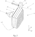
- Figures 1, 1a and 2 each shows a schematic representation of a motor vehicle light module (or a part of the motor vehicle light module) for a headlight, in particular motor vehicle headlight, which may correspond to a light module according to the invention.
- a motor vehicle light module is particularly well suited for motor vehicle headlights, in which a compact design is in the foreground and from a single and preferably continuous light exit surface several light functions (for example, a main and at least one secondary light function) should preferably be realized simultaneously.
- this light exit surface corresponds to a light exit surface of an exit optics 22 of at least one projection device 2 (see also FIG FIGS. 1 to 15 ).
- the motor vehicle light module has at least one light source 1 , for example an LED light source.
- the at least one light source 1 is preceded by a collimator 9 .
- the projection device 2 also has an entrance optics 21 .
- the entry optics 21 and the exit optics 22 are arranged, an intermediate image of light emitted by the at least one light source 1, preferably collimated by the collimator 9 in a light lying between the entrance optics 21 and the exit optics 22, substantially transverse to an optical axis of the projection device 2 standing intermediate image plane to form.
- the exit optics 22 is set up to image the intermediate image in the form of a light distribution of a first predetermined type into an area in front of the motor vehicle light module.
- the first type of light distribution may be, for example, a main light function light distribution - ie a light distribution which is generated when the main light function of the motor vehicle light module is activated.
- a main light function light distribution may be a low beam distribution or (for example, adaptive or glare-free) high beam distribution.
- At least one additional light source - so-called additional light source 3a, 3c - is provided, which at least one second additional light source 3a, 3c is arranged to emit light between the entrance optics 21 and the exit optics 22.
- the at least one additional light source 3a, 3c is preferably not a point light source. It is advantageous if the at least one additional light source 3a, 3c extends spatially and occupies a predetermined area between the entrance optics 21 and the exit optics of the projection device.
- the at least one additional light source 3a, 3b , 3c, 3d (see also FIGS. 7 to 15 ) comprise a luminous means 32 which lies outside the region between the entrance optics 21 and the exit optics 22.
- the light emitted by the at least one additional light source 3a, 3b is imaged by means of the exit optics 22 in the (same) area in front of the light module in the form of a light distribution of a second predetermined type.
- the second type of light distribution is a secondary light function light distribution - ie a light distribution which is generated when the secondary light function of the motor vehicle light module is actuated.
- logos, welcome light functions can be realized.
- the entrance optics 21 and the at least one additional light source 3a, 3c are formed and assigned to one another such that neither the at least one additional light source 3a, 3c nor the light emitted by the at least one additional light source 3a, 3c illuminates the intermediate image changes.
- the light generated by the at least one additional light source 3a, 3b, 3c, 3d leaves the intermediate image generated with the light of the at least one light source 1 unaffected / unimpaired / unchanged.
- the at least one additional light source 3a, 3c generates in the intermediate image plane an additional / second intermediate image which does not overlap the (original) intermediate image.
- the light generated by the at least one light source 1 propagates according to (or along) a first beam path 100 and the light generated by the at least one additional light source 3a, 3b, 3c, 3d according to a second, different beam path 300a , 300b , 300c , 300d through the optical projection device 2 (see in particular FIGS. 7 to 15 ). It is expedient if the at least one additional light source 3a, 3b, 3c, 3d outside of the first beam path 100 - that is not in the first beam path - is.
- the at least one additional light source 3a, 3b, 3c, 3d is set up to produce collimated light, which is substantially parallel to the optical axis of the projection device 2.
- the entrance optics 21 and the exit optics 22 are arranged as matrix-like arrays of micro entrance optics 210 or micro exit optics 220 - micro entrance optics array or micro exit optics - in planes perpendicular to the optical axis of the optical projection device 2.
- Array - are formed, each micro-entry optics 210 at least one, preferably exactly one micro-exit optics 220 corresponds such that they have a common, preferably horizontally extending, optical axis and form a micro-optical system.
- the micro-input / output optics 210, 220 may be formed, for example, as convex lenses.
- the direction of the optical axis of each micro-optics system preferably coincides with the main emission direction Z.
- common optical axis of two optics means that the optical axes of these two optics substantially coincide.
- the at least one additional light source 3a, 3b, 3c, 3d may have a plurality of spaced light emission regions 30a, 30b, 30c, 30d for emitting the light between the entrance optics 21 and the exit optics 22 (see in particular FIGS. 9 to 15 ), which Lichtabstrahl Schemee 30a, 30b, 30c, 30d in a plane substantially transverse to the optical axis of the projection device 2 - in the so-called Lichtabstrahlebene are arranged.
- this plane is arranged between the entrance optics 21 and the exit optics 22.
- a light bundle 300a, 300b, 300c, 300d is generated, which propagates parallel to the optical axis of the projection device 2.
- the Lichtabstrahl Schemee 30a, 30b, 30c, 30d of the exit optics 22 are assigned. It is particularly advantageous if each light emission area of a region of the exit optics 22, for example one - if the exit optics is designed as a micro exit optics array - is associated with individual micro exit optics 210 or a horizontal row of the micro exit optics.
- the decoupling element is located on the rear side of the luminous element (with respect to the emission direction Z). The deflected by the coupling element light exits at the opposite side by a curved exit surface of the filament.
- the emission characteristic of the luminous element it is possible to influence the emission characteristic of the luminous element by shaping that region of the exit surface at which the light leaves the luminous element.
- the abovementioned assignment of the light emission regions 30a, 30b, 30c, 30d of the exit optics 22 can serve, for example, for the curvature of the exit optics 22, for example their micro exit optics 210, to be shaped by the at least one additional light source 3a, 3b, 3c , 3d generated photo is used.
- the light image can therefore be designed on the one hand via the size and / or shape of the Lichtabstrahl Schemee 30a, 30b, 30c, 30d of the at least one additional light source 3a, 3b, 3c, 3d and / or on the imaging properties of the exit optics 22, such as its thickness or thickness of the micro-exit optics 220 and / or shape of a Light exit surface, for example (local / global) curvature.
- the efficiency of the at least one additional light source 3a, 3b, 3c, 3d is increased.
- the at least one additional light source 3a, 3c has a light guide element 31a, 31c and the already briefly mentioned light source 32, wherein the light source 32 is associated with the light guide element 31a, 31c.
- the lighting means 32 is preferably designed as an LED lighting means.
- the Lichtabstrahl Schemee 30a, 30b, 30c, 30d (in FIGS. 1 and 2 not visible) are preferably arranged in the light guide element 31a, 31b, 31c, 31d.
- the luminous means 32 does not lie between the entrance optics 21 and the exit optics 22, like the ones shown in FIG Figures 1, 1a and 2 demonstrate.
- the luminous means 32 can be designed as an LED illuminant.
- both the LED light source 1 and the LED illuminant 32 are mounted on a common printed circuit board.
- the LED light source 1 and the LED illuminant 32 can each have a plurality of LEDs, wherein both the LEDs of the LED light source 1 and the LEDs of the LED illuminant 32 are in a plane substantially perpendicular to the optical axis of the projection device 2 are arranged and preferably emit light in the direction of the optical axis.
- the LED lighting means three side by side (not shown) or one above the other (see FIG. 1a ) arranged LEDs have.
- An arrangement of the LED illuminant from above / below makes it possible to arrange a plurality of projection devices 2 side by side in a motor vehicle headlight.
- the optical waveguide element may be formed as a light guide plate 31a, 31b, 31c, 31d , which (in the region between the entrance optics 21 and the exit optics 22) is arranged substantially transversely to the optical axis of the projection device 2.
- a reference to the above-mentioned prior art is appropriate.
- WO 2017/066818 A1 all show light modules - so-called microprojection light modules - in which micro-entry optics array and micro-exit optics array each applied to a substrate plate, such as a glass plate, in particular glued.
- the substrate plates are often present because the micro-entry optics or micro-exit optics of the microprojection light modules can already be arranged during production on such a glass carrier / substrate plate.
- optical properties, such as focal length, of the lenses (micro-optics) be specified. If a certain focal length is desired, it can be achieved by varying the "thickness" of the substrate plates.
- the micro-entry optics, micro-exit optics can be made of polycarbonate (PC) and arranged on a substrate plate made of crown glass (for example, B270® glass), for example, be glued.
- Optical fiber element may be made of polycarbonate, for example.
- the thickness, ie the extent in the direction of an optical axis, of the entire projection device is also predetermined.
- Substrate plates for the micro entrance optics array or micro exit optics array can be different in thickness. This has the same reason: the thickness of the projection device is practically predetermined by the fixed dimensions of the lenses in the micro entrance optics array or micro exit optics array.
- one or more aperture (s) may be provided, which also on a substrate plate - so-called Shuttersubstrat (shutter - borrowed from the English for aperture) - is (are) applied. In this case, the thickness of the projection device can be reduced in the manufacturing process such that the shutter substrate can be inserted.
- one or more of the light guide plates 31a, 31b, 31c, 31d are formed as a substrate plate of the micro entrance optics array and / or the micro exit optics array or as a shutter substrate.
- the light guide plate 31a, 31b, 31c, 31d has at least one, preferably laterally or below or above the light guide plate 31a, 31b, 31c, 31d arranged Lichteinkoppel reaction 310a, 310c for coupling light 320a, 320c of the bulb 32, which light in the light guide plate propagates and exits at the light emitting portions 30a, 30b, 30c, 30d from the light guide plate.
- Specialist knowledge includes the knowledge that the coupled-in light propagates in a light guide due to total reflection.
- FIGS. 1 and 2 show light guide plates, which are formed in the region between the entrance optics 21 and the exit optics 22 plan and outside of this region have a bent portion 330 a, 330 c.
- the light guide plates 31a, 31c shown are preferably bent towards their light coupling surfaces 310a, 310c.
- the abovementioned arrangement of the at least one light source 1 and of the luminous means 32 is made possible in a common plane which is essentially perpendicular to the optical axis.
- the light 320a, 320c emitted by the respective luminous means 32 parallel to the optical axis of the projection device 2 is transmitted via the respective one Illuminant 32 coupled light input surface 310a, 310c coupled into the light guide plate 31a, 31c, propagates due to the total reflection through the bent portion 330a, 330c in the lying between the entrance optics 21 and the exit optics 22 area of the light guide plate 31a, 31c and is at the Lichtabstrahl Suiteen 30a, 30b, 30c, 30d are coupled out substantially parallel to the optical axis of the projection device 2.
- each light emission region 30a, 30b, 30c, 30d has a plurality of light extraction prisms.
- prisms with an angle of incidence of approximately 40 °, which decouple the light in parallel have proven to be practicable.
- the angle of attack can also be varied, so that a uniform light extraction takes place.
- the light extraction prisms are arranged to couple out the light from the light guide plate 31a, 31b, 31c, 31d in a direction substantially parallel to the optical axis.
- the light extraction prisms are preferably perpendicular to the propagation direction of the light in the light guide plate.
- the at least one additional light source 3a, 3b preferably replaces the substrate plate for the entrance optics 21 and / or exit optics 22, the entrance optics 21 and the exit optics 22 are each referred to as micro entrance optics.
- the intermediate regions 211 of the micro-entrance optical array are characterized in that they have no micro-entry optics - in this case no convex lens. In this Meaning, the light penetrating into the projection device through these intermediate regions 211 is irrelevant to the formation of the intermediate image and thus irrelevant to the first light function.
- the Lichtabstrahl Scheme 30a, 30b are in the Lichtabstraussie preferably (see FIG. 1a ) distributed like a checkerboard.
- the intermediate regions 211 are likewise distributed in a checkerboard pattern in the micro-entrance optics array, the light emission regions 30a, 30b being arranged downstream of the intermediate regions 211 (viewed in the direction of the optical axis of the projection device 2).
- the intermediate regions 211 are designed to be impermeable to light or a shielding element 23 is provided with the opaque shielding regions 230 corresponding to the intermediate regions 211 (see FIG FIG. 3 ).
- the shielding element 23 serves, for example, to shield the intermediate regions 211 from the light of the at least one light source 1.
- the light of the at least one light source 1 does not impinge on the light emission regions 30, is not scattered thereon. This leads to the reduction of unwanted scattered light.
- the shielding element 23 is preferably arranged in a plane orthogonal to the optical axis of the optical projection device 2 and preferably extends over substantially the entire light entry surface of the entrance optics 21.
- the shielding element 23 is arranged on the light entry side with respect to the entrance optics 21, for example at a light entry surface of the entrance optics 21, in particular on the light entry surface of the entrance optics 21 is applied, and preferably the light generated by the at least one light source 1 on the micro light.
- entry optics 210 can not come up with the intermediate regions 211 of the micro entrance optics array.
- the shielding member 23 may, as FIG. 3 it can be seen to be formed as a planar aperture with a plurality of the opaque shielding regions 230 complementary breakthroughs. However, it is also conceivable that the shielding element 23 is formed as a continuous layer, wherein this layer has regions of different light transmittance / transparency. It is also conceivable that the translucency / transparency of these areas in a controlled manner, such as in a liquid crystal display, is changeable.
- the at least one additional light source 3a can function as a carrier / carrier element for the entry optics 21 ( FIGS. 1 and 7 to 9 ).
- the entrance optics 21 is arranged on one of the at least one first light source 1 facing side of the at least one additional light source 3a, for example applied, in particular glued.
- the at least one additional light source 3a can function as a carrier / carrier element for the exit optics 22 ( FIG. 10 ).
- the exit optics 22 on one of the at least one first light source 1 opposite side of the at least one additional light source 3a is arranged, for example applied, in particular glued.
- the light emission regions 30a of the first additional light source 3a and the light emission regions 30b of the second auxiliary light source 3b prefferably be configured and positioned relative to one another in such a way that light rays 300a, 300b generated by the corresponding light emission regions 30a, 30b are in different directions spread out non-overlapping areas of the projection device 2.
- FIGS. 7 to 11 it can be seen that the Lichtabstrahl Schemee 30a and 30b can emit collimated light parallel to the optical axis of the projection device.
- the light-emitting regions 30a and 30b are dimensioned and positioned such that light rays 300a emitted by first light-emitting regions 30a are parallel to, for example, above (FIG. Fig. 10 ) of light beams 300b radiated from second light emitting areas 30b.
- the first light emission regions 30a are positioned below an optical axis of a corresponding micro exit optics 220, the rays 300a at this micro exit optics 220 are refracted and imaged in an area above the horizon (HH line).
- the rays 300b on this micro exit optics 220 are refracted and imaged into an area below the horizon.
- a first additional light source 3a a light distribution emitted above the horizon can be generated - for example a Signlight light distribution and with a second additional light source 3b a light distribution lying below the horizon - for example a daytime running light or direction indicator light distribution can be realized ,
- the projection device 2 can have at least one diaphragm device 7, 8 which lies between the inlet optics 21 and the outlet optics 22 and which has at least one diaphragm device 7, 8 the apertures 70 corresponding to the intermediate regions 211 (see FIG FIG. 4 ).
- the diaphragm device 7, 8 can be configured to form the intermediate image, for example to create a low-beam distribution with an asymmetrical cut-off line, and / or to correct optical aberrations.
- the diaphragm device 7, 8 may comprise a plurality of diaphragms.
- the shape of the at least one diaphragm device 7, 8 depends on the light distribution of the first and / or the second type to be generated.
- the diaphragm device 7 can, for example, on the light exit side of the light guide plate 31a, 31b are applied and has an array of openings 70, which takes into account the intermediate regions 211 in the micro-entrance optical array or the opaque areas of the shielding element 23.
- a first diaphragm element 4, 5 is provided, which first diaphragm element 4, 5 is the Lichtabstrahl Schemeen 30c, 30d upstream and is arranged to shield at least the Lichtabstrahl Societye 30c, 30d of the light of the at least one first light source 1.
- respective opaque areas 40, 50 are provided in the first panel member 4, 5 for shielding the light emitting areas 30c, 30d.
- the at least one additional light source 3c carries the first diaphragm element 4, 5 (FIG. FIG. 2 ).
- the light guide plate can simultaneously represent the holder for the microlens array (micro entrance optics array and / or micro exit optics array). This simplifies the system, because in this case, the light guide plate can take the place of the substrate plate for micro-entry optics or micro-exit optics, whereby insertion loss of the projection device is reduced but also required space is smaller.
- the at least one additional light source 3c carries the function of such a carrier.
- the Lichtabstrahl Societye 30c, 30d in the Lichtabstraussie the at least one additional light source 3c, 3d for example, a shape horizontally, transversely to the optical axis of the optical projection device 2 / to the main emission direction Z extending, vertically (in the direction of V) from each other, preferably equidistantly spaced Have stripes.
- the diaphragm element 4, 5 it is expedient for the diaphragm element 4, 5 to have light-impermeable regions 40, 50 corresponding to these strips (see FIG FIGS. 5 and 6 ).
- the light emission regions 30c, 30d are preferably arranged directly (for example 0-5 mm) after, for example, on the first diaphragm element 4, 5.
- the first diaphragm element 4, 5 is preferably arranged between the entrance optics 21 formed, for example, as the abovementioned micro entrance optics array, and the light emission areas 30c, 30d.
- the first diaphragm element 5 can be set up to form the intermediate image for a low-beam light distribution from the light emitted by the at least one light source 1.
- a diaphragm element may for example have a plurality of corresponding openings.
- aperture element 4, 5 is applied on the light exit side with respect to the entrance optics 21 on the side of the light guide plate 31c, 31d facing the at least one light source 1.
- first additional light source 3c carrying at least the first diaphragm element 4, 5
- second additional light source 3d carrying the exit optical system 22 (see FIG FIGS. 14 and 15 ) and the first diaphragm element 4, 5 is disposed in front of the light-emitting regions 30c of the first auxiliary light source 3c.
- the exit optics in particular the micro exit optics array on one of the at least one first light source 1 side facing away from the second additional light source 3d arranged, for example applied, in particular glued.
- the light-emitting regions 30c of the first auxiliary light source 3c and the light-emitting regions 30d the second additional light source 3d are designed and positioned relative to one another such that light beams 300c, 300d generated by the corresponding light emission regions 30c, 30d propagate in different, non-overlapping regions of the projection device 2.
- a second diaphragm element 6 can be provided.
- the second diaphragm element 6 can, for example, limit and / or collimate light emitted by the first additional light source 3c (see, for example, FIGS FIG. 13 and 15 ).
- the second diaphragm element 6 can be arranged in front of the light emission regions 30d of the second additional light source 3d. It is advantageous if the second diaphragm element is set up to shield the second additional light source 3d.
- the first diaphragm element 4, 5 and the second diaphragm element 6 may additionally be arranged to form the intermediate image, for example one To provide low-beam light distribution with an asymmetrical cut-off line, and / or to correct optical aberrations ( FIGS. 12 to 15 ).
- the first diaphragm element 4, 5 and the second 6 may be formed as a planar diaphragm with a plurality of apertures.
- FIGS. 12 to 15 show sectional views of an enlarged portion of a projection device of a motor vehicle light module according to a second embodiment with different numbers of aperture elements 4, 5, 6 and additional light sources 30c, 30d.
- the at least one accessory light source may replace the shutter substrate or micro exit optics array substrate plate - the micro exit optics array substrate plate.
- FIGS. 12 to 15 It can be seen that the Lichtabstrahl Societye 30c and 30d collimated light 300c, 300d, preferably parallel to the optical axis of the Radiate projection device 2.
- the light-emitting regions 30c and 30d are dimensioned and positioned such that light rays 300c emitted by first light-emitting regions 30c are parallel to, for example, above (FIG. FIGS. 14 and 15 ), Light beams 300d radiated from second light emitting portions 30d extend.
- the beams 300c are broken at this micro-exit optics 220 and into a Area shown above the horizon.
- the horizon is often referred to as "line HH" or "HH line”. This is a line corresponding to the horizon on a measuring screen on which light distributions generated by light modules are measured in a motor vehicle lighting technology laboratory.
- Line HH is part of the screen coordinate system that is common in automotive lighting technology.
- Line HH is a horizontal line that runs parallel to the road surface (in the laboratory - imaginary roadway) and through an intersection HV of the photometric beam axis from the center of the light module to the screen. The point HV is the origin of the screen coordination system.
- the rays 300d are refracted at this micro exit optics 220 and into one Area shown below the horizon.
- a light distribution emitted above the horizon can be generated - for example a signal light distribution and with a second additional light source 3d a light distribution lying below the horizon - for example a daytime running light or direction indicator light distribution become.
- the light emission regions 30c, 30d are arranged, preferably directly, on or behind the corresponding opaque region of the corresponding (first or second) diaphragm element 4, 5, 6.
- the first additional light source 3c also carries the second diaphragm element 6.
- the second diaphragm element 6 on one of the at least one first light source 1 opposite side of the first additional light source 3c preferably the light guide plate 31c, 31d, arranged, for example applied, in particular glued.
- a deployable light module for a motor vehicle headlight has other parts that have not been explicitly mentioned in connection with the present invention. These other parts are (exemplary but not exhaustive) heat sink, support frame, mechanical and / or electrical actuators, covers and so on and immediately. For the sake of simplicity, however, the description of these standard components of a light module is omitted here.
Abstract
Lichtmodul für einen Kraftfahrzeugscheinwerfer umfassend: zumindest eine Lichtquelle (1) sowie zumindest eine Projektionseinrichtung (2), wobei die Projektionseinrichtung (2) eine Eintrittsoptik (21) und eine Austrittsoptik (22) aufweist, wobei die Eintrittsoptik (21) eingerichtet ist, ein Zwischenbild aus von der zumindest einen Lichtquelle (1) abgestrahltem Licht in einer zwischen der Eintrittsoptik (21) und der Austrittsoptik (22) liegenden, im Wesentlichen quer zu einer optischen Achse der Projektionseinrichtung (2) stehenden Zwischenbildebene zu formen, und die Austrittsoptik (22) eingerichtet ist, das Zwischenbild in Form einer Lichtverteilung eines ersten vorgegebenen Typs in einen Bereich vor dem Lichtmodul abzubilden, wobei zumindest eine Zusatz-Lichtquelle (3a, 3b, 3c, 3d) vorgesehen ist, welche zumindest eine Zusatz-Lichtquelle (3a, 3b, 3c, 3d) eingerichtet ist, Licht zwischen der Eintrittsoptik (21) und der Austrittsoptik (22) abzustrahlen; die Austrittsoptik (22) eingerichtet ist, das von der zumindest einen Zusatz-Lichtquelle (3a, 3b, 3c, 3d) abgestrahlte Licht in den Bereich vor dem Lichtmodul in Form einer Lichtverteilung eines zweiten vorgegebenen Typs abzubilden; die Eintrittsoptik (21) und die zumindest eine Zusatz-Lichtquelle (3a, 3b, 3c, 3d) derart ausgebildet und derart einander zugeordnet sind, dass weder die zumindest eine Zusatz-Lichtquelle (3a, 3b, 3c, 3d) noch das von der zumindest einen Zusatz-Lichtquelle (3a, 3b, 3c, 3d) abgestrahlte Licht das Zwischenbild ändert.Light module for a motor vehicle headlight comprising: at least one light source (1) and at least one projection device (2), wherein the projection device (2) has an entrance optics (21) and an exit optics (22), wherein the entrance optics (21) is arranged, an intermediate image from the at least one light source (1) emitted light in a between the entrance optics (21) and the exit optics (22) lying, substantially transversely to an optical axis of the projection device (2) standing intermediate image plane to form, and the exit optics (22) is arranged to image the intermediate image in the form of a light distribution of a first predetermined type in an area in front of the light module, wherein at least one additional light source (3a, 3b, 3c, 3d) is provided which at least one additional light source (3a, 3b, 3c, 3d) is arranged to emit light between the entrance optics (21) and the exit optics (22); the exit optics (22) is arranged to image the light emitted by the at least one additional light source (3a, 3b, 3c, 3d) into the area in front of the light module in the form of a light distribution of a second predetermined type; the entrance optics (21) and the at least one additional light source (3a, 3b, 3c, 3d) are designed and assigned to one another in such a way that neither the at least one additional light source (3a, 3b, 3c, 3d) nor that of the at least one additional light source (3a, 3b, 3c, 3d) radiated light changes the intermediate image.
Description
Die Erfindung betrifft ein Lichtmodul für einen Kraftfahrzeugscheinwerfer zum (vorzugsweise gleichzeitigen) Realisieren zumindest einer Haupt- und zumindest einer Neben-Lichtfunktion umfassend zumindest eine Lichtquelle sowie zumindest eine Projektionseinrichtung, wobei die Projektionseinrichtung eine Eintrittsoptik und eine Austrittsoptik aufweist, wobei die Eintrittsoptik eingerichtet ist, ein Zwischenbild aus von der zumindest einen Lichtquelle abgestrahltem Licht in einer zwischen der Eintrittsoptik und der Austrittsoptik liegenden, im Wesentlichen quer zu einer optischen Achse der Projektionseinrichtung stehenden Zwischenbildebene zu formen, und die Austrittsoptik eingerichtet ist, das Zwischenbild in Form einer Lichtverteilung eines ersten vorgegebenen Typs in einen Bereich vor dem Lichtmodul abzubilden.The invention relates to a light module for a motor vehicle headlight for (preferably simultaneously) realizing at least one main and at least one secondary light function comprising at least one light source and at least one projection device, wherein the projection device has an entry optics and an exit optics, wherein the entry optics is set up Intermediate image from the at least one light source radiated light in a lying between the entrance optics and the exit optics, substantially transverse to an optical axis of the projection device intermediate image plane to form, and the exit optics is arranged, the intermediate image in the form of a light distribution of a first predetermined type in to map an area in front of the light module.
Weiters betrifft die Erfindung einen Kraftfahrzeugscheinwerfer mit zumindest einem solchen Lichtmodul.Furthermore, the invention relates to a motor vehicle headlight with at least one such light module.
Lichtmodule der oben genannten Art sind aus dem Stand der Technik bekannt. Die internationale Anmeldung der Anmelderin
In der internationalen Anmeldung
Weiters zeigt die internationale Anmeldung
Ein Nachteil der oben genannten Lichtmodule ist, dass mit einem einzigen Lichtmodul nur eine sehr begrenzte Anzahl an Lichtverteilungen erzeugt und folglich Lichtfunktionen realisiert werden kann (niedrige Effizienz). Vor allem ist nachteilhaft, dass solche Lichtmodule keine Möglichkeit bieten, aus der gleichen Lichtaustrittsfläche des Lichtmoduls eine Neben-Lichtfunktion, wie Fahrtrichtungsanzeige (statisch oder dynamisch, beispielsweise als Lauflicht), Positionslicht und/oder Tagfahrlicht (statisch oder als Lauflicht) usw. und eine Hauptlichtfunktion, wie Abblendlicht, Fernlicht, Lichtfunktionen eines Adaptiven Frontlicht Systems (Lichtfunktionen eines AFS-Scheinwerfers) zu realisieren.A disadvantage of the above-mentioned light modules is that only a very limited number of light distributions can be generated with a single light module, and consequently light functions can be realized (low efficiency). Above all, it is disadvantageous that such light modules offer no possibility of the same light exit surface of the light module a secondary light function, such as direction indicator (static or dynamic, for example as running light), position light and / or daytime running lights (static or as running light), etc. and a main light function, such as low beam, high beam, light functions of an adaptive front light system (light functions of an AFS headlamp ) to realize.
Die Aufgabe der vorliegenden Erfindung besteht darin, die herkömmliche Lichtmodule dahingehend zu verbessern, beziehungsweise deren Aufbau so zu erweitern, dass aus der Lichtaustrittsfläche desselben Lichtmoduls mehrere Lichtfunktionen, vorzugsweise gleichzeitig erzeugt werden können.The object of the present invention is to improve the conventional light modules to the effect, or to expand their structure so that from the light exit surface of the same light module several light functions, preferably can be generated simultaneously.
Die Aufgabe wird mit einem Lichtmodul der oben genannten Art dadurch gelöst, dass zumindest eine zusätzliche Lichtquelle - so genannte Zusatz-Lichtquelle - vorgesehen ist, welche zumindest eine Zusatz-Lichtquelle eingerichtet ist, Licht zwischen der Eintrittsoptik und der Austrittsoptik abzustrahlen (in diesem Bereich gibt die zumindest eine Zusatz-Lichtquelle Licht ab); die Austrittsoptik eingerichtet ist, das von der zumindest einen Zusatz-Lichtquelle abgestrahlte Licht in den Bereich vor dem Lichtmodul in Form einer Lichtverteilung eines zweiten vorgegebenen Typs abzubilden; die Eintrittsoptik und die zumindest eine Zusatz-Lichtquelle derart ausgebildet und derart einander zugeordnet sind, dass weder die zumindest eine Zusatz-Lichtquelle noch das von der zumindest einen Zusatz-Lichtquelle abgestrahlte Licht das Zwischenbild ändert.The object is achieved with a light module of the type mentioned above in that at least one additional light source - so-called additional light source - is provided, which is arranged at least one additional light source to emit light between the entrance optics and the exit optics (in this area there the at least one additional light source emits light); the exit optics is set up to image the light emitted by the at least one additional light source into the area in front of the light module in the form of a light distribution of a second predetermined type; the entrance optics and the at least one additional light source are designed and assigned to one another such that neither the at least one additional light source nor the light emitted by the at least one additional light source alters the intermediate image.
Dabei beeinflusst das von der zumindest einen Zusatz-Lichtquelle erzeugte Licht das mit dem Licht der zumindest einen Lichtquelle erzeugte Zwischenbild nicht. Vorzugsweise erzeugt die zumindest eine Zusatz-Lichtquelle in der Zwischenbildebene ein zusätzliches/zweites Zwischenbild, welches das (ursprüngliche, mit dem Licht der zumindest einen Lichtquelle erzeugte) Zwischenbild nicht überlappt.In this case, the light generated by the at least one additional light source does not influence the intermediate image produced with the light of the at least one light source. Preferably, the at least one additional light source generates in the intermediate image plane an additional / second intermediate image which does not overlap the (original, generated with the light of the at least one light source) intermediate image.
Denkbar ist, dass der zumindest einen Lichtquelle ein Kollimator nachgelagert ist.It is conceivable that the at least one light source is downstream of a collimator.
Dadurch kann beispielsweise erreicht werden, dass die Lichtverteilung des ersten vorgegebenen Typs die Lichtverteilung des zweiten vorgegebenen Typs im Lichtbild nicht überlappt, obwohl diese aus der gleichen Lichtaustrittsfläche des Lichtmoduls ausgestrahlt werden. Solche Lichtverteilungen können zum Realisieren unterschiedlicher Lichtfunktionen genutzt werden.As a result, it can be achieved, for example, that the light distribution of the first predetermined type does not overlap the light distribution of the second predetermined type in the light image, although it is emitted from the same light exit surface of the light module become. Such light distributions can be used to realize different light functions.
Beispielsweise können die Eintrittsoptik und die zumindest eine Zusatz-Lichtquelle derart ausgebildet und derart einander zugeordnet sein, dass das von der zumindest einen Lichtquelle erzeugte Licht gemäß (oder entlang) einem ersten und das durch die zumindest eine Zusatz-Lichtquelle erzeugte Licht gemäß einem zweiten, unterschiedlichen Strahlengang durch die optische Projektionseinrichtung verläuft. Dabei ist es zweckdienlich, wenn die zumindest eine Zusatz-Lichtquelle außerhalb des ersten Strahlengangs - also nicht in dem ersten Strahlengang - liegt, sodass weder die zumindest eine Zusatz-Lichtquelle noch das von der zumindest einen Zusatz-Lichtquelle abgestrahlte Licht das Zwischenbild ändert.For example, the entrance optics and the at least one additional light source can be designed and assigned to each other such that the light generated by the at least one light source according to (or along) a first and the light generated by the at least one additional light source according to a second, different beam path passes through the optical projection device. It is expedient if the at least one additional light source is outside the first beam path - ie not in the first beam path - so that neither the at least one additional light source nor the light emitted by the at least one additional light source changes the intermediate image.
Es kann zweckmäßig sein, wenn die zumindest eine Zusatz-Lichtquelle eingerichtet ist, kollimiertes, zu der optischen Achse der Projektionseinrichtung im Wesentlichen paralleles Licht zu erzeugen. Dies hat zum Vorteil, dass hinsichtlich eines mit der zumindest einen Zusatz-Lichtquelle erzeugten Lichtbildes eine genaue Position der zumindest einen Zusatz-Lichtquelle zwischen der Eintrittsoptik und der Austrittsoptik und insbesondere hinsichtlich der Zwischenbildebene nicht relevant, wodurch das Justieren des Lichtmodul einfacher wird. Es kann sogar von Vorteil sein, wenn die zumindest eine Zusatz-Lichtquelle nicht in der Zwischenbildebene angeordnet ist.It may be expedient if the at least one additional light source is set up to produce collimated light which is substantially parallel to the optical axis of the projection device. This has the advantage that with respect to a light image generated with the at least one additional light source, an exact position of the at least one additional light source between the entrance optics and the exit optics and in particular with respect to the intermediate image plane is not relevant, whereby the adjustment of the light module is easier. It may even be advantageous if the at least one additional light source is not arranged in the intermediate image plane.
Weitere Vorteile ergeben sich, wenn die Eintrittsoptik und die Austrittsoptik als matrixartige, in quer zur optischen Achse der optischen Projektionseinrichtung stehenden Ebenen angeordnete Arrays von Mikro-Eintrittsoptiken beziehungsweise Mikro-Austrittsoptiken - Mikro-Eintrittsoptik-Array beziehungsweise Mikro-Austrittsoptik-Array - ausgebildet sind, wobei jeder Mikro-Eintrittsoptik zumindest eine, vorzugsweise genau eine Mikro-Austrittsoptik derart korrespondiert, dass sie eine gemeinsame, vorzugsweise horizontal verlaufende, optische Achse aufweisen und ein Mikro-Optiksystem bilden.Further advantages result if the inlet optics and the exit optics are embodied as matrix-like arrays of micro entrance optics or micro exit optics-micro entrance optics array and micro exit optics array, respectively, which are arranged transversely to the optical axis of the optical projection device. wherein each micro-entry optics at least one, preferably exactly one micro-exit optics corresponds such that they have a common, preferably horizontally extending, optical axis and form a micro-optical system.
Im Zusammenhang mit der vorliegenden Erfindung wird unter dem Begriff "gemeinsame optische Achse zweier Optiken" verstanden, dass die optischen Achsen dieser zwei Optiken im Wesentlichen zusammenfallen.In the context of the present invention, the term "common optical axis of two optics" means that the optical axes of these two optics substantially coincide.
Verwenden von sehr kleinen Optiken an der Lichtaustrittsfläche - Mikrooptiken mit charakteristischen Größen im Mikrometerbereich - führt zu einem gleichmäßigeren Erscheinungsbild von der Lichtaustrittsfläche sowohl in unbeleuchtetem als auch in beleuchtetem Zustand.Using very small optics at the light exit surface - micro-optics with characteristic sizes in the micrometer range - leads to a more uniform appearance of the light-emitting surface in both unlighted and illuminated state.
Weiters kann vorgesehen sein, dass die zumindest eine Zusatz-Lichtquelle eine Mehrzahl voneinander beabstandeter Lichtabstrahlbereiche zum Abstrahlen von dem Licht zwischen der Eintrittsoptik und der Austrittsoptik aufweist, welche Lichtabstrahlbereiche in einer im Wesentlichen quer zu der optischen Achse der Projektionseinrichtung stehenden Ebene - in der so genannten Lichtabstrahlebene - angeordnet sind. Es versteht sich, dass diese Ebene zwischen der Eintrittsoptik und der Austrittsoptik angeordnet ist. Vorzugsweise wird mithilfe eines jeden Lichtabstrahlbereichs ein Lichtbündel erzeugt, welches sich parallel zu der optischen Achse der Projektionseinrichtung ausbreitet.It can further be provided that the at least one additional light source has a plurality of spaced-apart Lichtabstrahlbereiche for emitting the light between the entrance optics and the exit optics, which Lichtabstrahlbereiche in a substantially transverse to the optical axis of the projection device level - in the so-called Lichtabstrahlebene - are arranged. It is understood that this plane is arranged between the entrance optics and the exit optics. Preferably, by means of each light emission region, a light beam is generated which propagates parallel to the optical axis of the projection device.
Darüber hinaus kann vorgesehen sein, dass die zumindest eine Zusatz-Lichtquelle ein Lichtleiterelement und ein dem Lichtleiterelement zugeordnetes Leuchtmittel, vorzugsweise ein LED-Leuchtmittel, aufweist, wobei die Lichtabstrahlbereiche in dem Lichtleiterelement angeordnet sind. Dabei kann es vorteilhaft sein, wenn das Leuchtmittel nicht zwischen der Eintrittsoptik und der Austrittsoptik liegt. Bei einer praxisbewahrten Ausführungsform kann vorgesehen sein, dass das Leuchtmittel und die zumindest eine Lichtquelle auf einem gemeinsamen Lichtquellen-Träger angeordnet sind. Beispielsweise, wenn die zumindest eine Lichtquelle und das Leuchtmittel als LED-Lichtquellen ausgebildet sind, können diese LED-Lichtquellen auf einer gemeinsamen Leiterplatte (auf demselben Print) angeordnet sein.In addition, it may be provided that the at least one additional light source has a light guide element and a light source associated with the light guide element, preferably an LED light source, wherein the Lichtabstrahlbereiche are arranged in the light guide element. It may be advantageous if the light source is not between the entrance optics and the exit optics. In a practical embodiment, it can be provided that the luminous means and the at least one light source are arranged on a common light source carrier. For example, if the at least one light source and the lighting means are designed as LED light sources, these LED light sources can be arranged on a common printed circuit board (on the same print).
Weiters kann vorgesehen sein, dass das Lichtleiterelement als eine im Wesentlichen quer zu der optischen Achse der Projektionseinrichtung angeordnete Lichtleiterplatte ausgebildet ist, wobei die Lichtleiterplatte zumindest eine Lichteinkoppelfläche zum Einkoppeln von Licht des Leuchtmittels, welches Licht sich in der Lichtleiterplatte ausbreitet und an den Lichtabstrahlbereichen aus der Lichtleiterplatte austritt. Es ist bekannt, dass das Ausbreiten von Licht innerhalb eines Lichtleiters aufgrund von Totalreflexion geschieht. Das Licht des Leuchtmittels kann seitlich oder von unten beziehungsweise von oben in die Lichtleiterplatte eingekoppelt werden. Nach dem Einkoppeln breitet sich das Licht (aufgrund von Totalreflexion) in Richtung des Bereichs zwischen der Eintrittsoptik und der Austrittsoptik. In Bereichs zwischen der Eintrittsoptik und der Austrittsoptik breitet sich das Licht in der Lichtleiterplatte im Wesentlichen quer zur optischen Achse der Projektionseinrichtung aus, bis es in den Lichtabstrahlbereichen umgelenkt wird und in eine zu der optischen Achse im Wesentlichen parallele Richtung aus der Lichtleiterplatte austritt.Furthermore, it can be provided that the light guide element is formed as a light guide plate arranged substantially transversely to the optical axis of the projection device, wherein the light guide plate at least one light input surface for coupling light of the light source, which propagates light in the light guide plate and at the Lichtabstrahlbereichen from the Light guide plate exits. It is known that the propagation of light within a light guide occurs due to total reflection. The light of the light source can be coupled laterally or from below or from above into the light guide plate. After coupling, the light propagates (due to total reflection) in the direction of the area between the entrance optics and the exit optics. In the area between the entrance optics and the exit optics, the light spreads in the area Light guide plate substantially transversely to the optical axis of the projection device until it is deflected in the Lichtabstrahlbereichen and emerges in a direction substantially parallel to the optical axis direction of the light guide plate.
Im Zusammenhang mit der vorliegenden Erfindung wird unter dem Begriff "Lichtleiterplatte" ein planes, sich in einer Ebene in zwei Richtungen erstreckendes Lichtleiterelement verstanden.In the context of the present invention, the term "light guide plate" is understood to mean a plane light guide element extending in a plane in two directions.
Es kann dabei zweckmäßig sein, wenn jeder Lichtabstrahlbereich eine Mehrzahl von Lichtauskoppelprismen aufweist. Dabei sind die Lichtauskoppelprismen vorzugsweise dazu eingerichtet, das Licht aus der Lichtleiterplatte in eine im Wesentlichen zur optischen Achse parallele Richtung auszukoppeln. Die Lichtauskoppelprismen stehen senkrecht zur Ausbreitungsrichtung des Lichts in der Lichtleiterplatte. Beispielsweise weisen die Lichtauskoppelprismen einen Anstellwinkel von ca. 40° auf.It may be expedient if each Lichtabstrahlbereich has a plurality of Lichtauskoppelprismen. In this case, the light extraction prisms are preferably configured to couple out the light from the light guide plate in a direction substantially parallel to the optical axis. The light extraction prisms are perpendicular to the propagation direction of the light in the light guide plate. For example, the light extraction prisms on an angle of about 40 °.
Eine Einspeisung (Einkoppeln) aus verschiedenen Seiten in die Lichtleiterplatte und eine entsprechende Anpassung (der Form) der Lichtauskoppelprismen kann dabei helfen, sogar mehrere (mehr als zwei) verschiedene Lichtfunktionen zu realisieren.Feeding (injecting) from different sides into the light guide plate and matching the shape of the light extraction prisms may help to realize even more (more than two) different light functions.
Bei einer vorteilhaften Ausführungsform kann vorgesehen sein, wenn das Mikro-Eintrittsoptik-Array eine Mehrzahl den Lichtabstrahlbereichen zugeordneter, vorzugsweise plan ausgebildeter Zwischenbereiche aufweist.In an advantageous embodiment, provision can be made for the micro-entry optical array to have a plurality of intermediate regions assigned to the light emission regions and preferably planar.
Die Mikro-Optiken des Mikro-Eintrittsoptik-Arrays und/oder des Mikro-Austrittsoptik-Arrays können beispielsweise als konvexe Linsen ausgebildet sein.The micro-optics of the micro-entrance optics array and / or the micro-exit optics array may be formed, for example, as convex lenses.
Die Zwischenbereiche des Mikro-Eintrittsoptik-Arrays weisen vorzugsweise keine Mikro-Eintrittsoptik auf und sind beispielsweise derart ausgebildet, dass Streuung von dem mittels der zumindest einen Lichtquelle erzeugten Licht reduziert wird. Wenn die zumindest eine Lichtquelle paralleles Licht erzeugt oder das Licht der zumindest einen Lichtquelle, beispielsweise durch einen Kollimator, kollimiert wird, eher es auf die Eintrittsoptik trifft, ist es besonders vorteilhaft die Zwischenbereiche plan auszubilden.The intermediate regions of the micro-entrance optical array preferably have no micro-entry optics and, for example, are designed such that scattering is reduced by the light generated by means of the at least one light source. If the at least one light source generates parallel light or the light of the at least one light source is collimated, for example, by a collimator, it is more likely to encounter the entrance optics, it is particularly advantageous to form the intermediate regions in a planar manner.
In diesem Sinne ist das durch diese Zwischenbereiche in die Projektionseinrichtung eindringende Licht für Bildung des Zwischenbildes und ergo für die erste Lichtfunktion irrelevant. Vorzugsweise kann dieses Licht abgeschirmt werden (siehe unten).In this sense, the light penetrating into the projection device through these intermediate regions is irrelevant to the formation of the intermediate image and thus to the first light function. Preferably, this light can be shielded (see below).
Es kann mit Vorteil vorgesehen sein, dass die Lichtabstrahlbereiche in der Lichtabstrahlebene schachbrettartig verteilt sind und die Zwischenbereiche in dem Mikro-Eintrittsoptik-Array schachbrettartig verteilt sind, wobei die Lichtabstrahlbereiche den Zwischenbereichen (in Richtung der optischen Achse) nachgeordnet sind. Beispielsweise bedeutet das, dass diese Anordnung ein in Richtung der optischen Achse der optischen Projektionseinrichtung gesehen, vorzugsweise aus Quadraten ausgebildetes, Schachbrettmuster ist. Dabei ist es zweckdienlich, wenn die Lichtabstrahlbereiche aufweisenden Bereiche des Schachbrettmusters komplementierende Bereiche des Schachbrettmusters den Zwischenbereichen korrespondierend angeordnet sind.It can be provided with advantage that the Lichtabstrahlbereiche are distributed checkerboard in the Lichtabstrahlebene and the intermediate areas in the micro-entrance optics array are distributed like a checkerboard, wherein the Lichtabstrahlbereiche the intermediate areas (in the direction of the optical axis) are arranged downstream. This means, for example, that this arrangement is a checkerboard pattern formed preferably in the direction of the optical axis of the optical projection device, preferably of squares. In this case, it is expedient for the areas of the checkerboard pattern comprising areas of the checkerboard pattern which comprise light-emitting areas to be arranged corresponding to the intermediate areas of the checkerboard pattern.
Darüber hinaus kann es zweckdienlich sein, wenn die Zwischenbereiche lichtundurchlässig ausgebildet sind. Es kann außerdem ein Abschirmelement mit den Zwischenbereichen korrespondierenden lichtundurchlässigen Abschirmbereichen vorgesehen sein, welches Abschirmelement die Zwischenbereiche von dem Licht der zumindest einen Lichtquelle abschirmt.In addition, it may be expedient if the intermediate regions are made opaque. In addition, a shielding element may be provided with the intermediate regions of corresponding opaque shielding regions, which shielding element shields the intermediate regions from the light of the at least one light source.
Außerdem kann es vorteilhaft sein, wenn die zumindest eine Zusatz-Lichtquelle als Träger für die Eintrittsoptik oder die Austrittsoptik ausgebildet ist. Vorzugsweise ist die Eintrittsoptik oder die Austrittsoptik, welche beispielsweise als das Mikro-Eintrittsoptik-Array beziehungsweise das Mikro-Austrittsoptik-Array aus Silikon sind, an der Zusatz-Lichtquelle angeordnet, beispielsweise auf sie aufgebracht, insbesondere mit dieser verbunden, beispielsweise verklebt ist. Dies ist besonders in Hinblick auf synergetische Nutzung von lichttechnisch relevanten Bauteilen eines Lichtmoduls vorteilhaft (zum Beispiel wenn die Substratplatte als Lichtleiter ausgenutzt wird).Moreover, it may be advantageous if the at least one additional light source is designed as a carrier for the entrance optics or the exit optics. Preferably, the entrance optics or the exit optics, which are for example as the micro entrance optics array or the micro exit optics array of silicone, arranged on the additional light source, for example, applied to them, in particular connected to this, for example glued. This is particularly advantageous with regard to the synergetic use of photometrically relevant components of a light module (for example, if the substrate plate is used as a light guide).
Vorzugsweise ist die Eintrittsoptik, insbesondere das Mikro-Eintrittsoptik-Array auf einer der zumindest einen ersten Lichtquelle zugewandten Seite der zumindest einen Zusatz-Lichtquelle angeordnet, beispielsweise aufgebracht, insbesondere geklebt.The entry optics, in particular the micro entrance optics array, are preferably arranged, for example applied, in particular glued, on a side of the at least one additional light source facing the at least one first light source.
Die Vielfalt von mit dem erfindungsgemäßen Lichtmodul realisierbaren Lichtfunktionen kann weiter vergrößert werden, wenn zwei Zusatz-Lichtquellen vorgesehen sind, wobei eine erste der zwei Zusatz-Lichtquellen die Eintrittsoptik trägt und eine zweite der zwei Zusatz-Lichtquellen die Austrittsoptik trägt.The variety of light functions that can be realized with the light module according to the invention can be further increased if two additional light sources are provided, wherein a first of the two additional light sources carries the entrance optics and a second of the two additional light sources carries the exit optics.
Vorzugsweise ist die Austrittsoptik, insbesondere das Mikro-Austrittsoptik-Array auf einer der zumindest einen ersten Lichtquelle abgewandten Seite der zweiten Zusatz-Lichtquelle angeordnet, beispielsweise aufgebracht, insbesondere geklebt.The exit optics, in particular the micro exit optics array, are preferably arranged, for example applied, in particular glued, on a side of the second additional light source facing away from the at least one first light source.
Weiters kann vorteilhaft sein, wenn die Lichtabstrahlbereiche der ersten Zusatz-Lichtquelle und die Lichtabstrahlbereiche der zweiten Zusatz-Lichtquelle derart ausgebildet und zueinander positioniert sind, dass sich von den entsprechenden Lichtabstrahlbereichen erzeugte Lichtstrahlen in unterschiedlichen, sich nicht überschneidenden Bereichen der Projektionseinrichtung ausbreiten. Dabei können die Lichtabstrahlbereiche der zumindest einen oder allen Zusatz-Lichtquellen in für den Strahlengang des von der zumindest einen Lichtquelle, die beispielsweise Licht für die Hauptlichtfunktion abstrahlt, abgestrahlten unwesentlichen Bereichen platziert werden. Dadurch wird die Hauptlichtfunktion nicht beeinträchtigt.Furthermore, it can be advantageous if the light emission regions of the first additional light source and the light emission regions of the second additional light source are designed and positioned relative to one another such that light rays generated by the corresponding light emission regions propagate in different, non-overlapping regions of the projection device. In this case, the light emission regions of the at least one or all additional light sources can be placed in the unimportant regions emitted by the at least one light source, which emits, for example, light for the main light function. This will not affect the main light function.
Darüber hinaus kann vorgesehen sein, dass die Projektionseinrichtung zumindest eine zwischen der Eintrittsoptik und der Austrittsoptik liegende Blendenvorrichtung aufweist, welche zumindest eine Blendenvorrichtung den Zwischenbereichen entsprechende Durchbrüche aufweist und eingerichtet ist, das Zwischenbild (beispielsweise für eine Abblendlichtverteilung) zu formen und/oder optische Abbildungsfehler zu korrigieren.In addition, it can be provided that the projection device has at least one aperture device located between the entrance optics and the exit optics, which has at least one aperture device apertures corresponding to the intermediate regions and is adapted to form the intermediate image (for example for a low-beam light distribution) and / or optical aberrations correct.
Bei einer weiteren bevorzugten Ausführungsform kann ein erstes Blendenelement vorgesehen sein, welches erste Blendenelement den Lichtabstrahlbereichen vorgelagert ist und die Lichtabstrahlbereiche von dem Licht der zumindest einen Lichtquelle abschirmt.In a further preferred embodiment, a first diaphragm element can be provided, which first diaphragm element is disposed in front of the light emission regions and shields the light emission regions from the light of the at least one light source.
Dabei kann es zweckdienlich sein, wenn das erste Blendenelement eingerichtet ist, aus dem von der zumindest einen Lichtquelle abgestrahlten Licht das Zwischenbild beispielsweise für eine Abblendlichtverteilung zu formen.It may be expedient if the first diaphragm element is set up to form the intermediate image from the light emitted by the at least one light source, for example for a low-beam light distribution.
Weiters kann es zweckmäßig sein, wenn die Lichtabstrahlbereiche in der Lichtabstrahlebene der zumindest einen Zusatz-Lichtquelle eine Form horizontal, quer zu der optischen Achse der optischen Projektionseinrichtung verlaufender, vertikal voneinander, vorzugsweise äquidistant beabstandeter Streifen aufweisen und das Blendenelement diesen Streifen entsprechende lichtundurchlässige Bereiche aufweist.Furthermore, it may be expedient if the Lichtabstrahlbereiche in the Lichtabstrahebene the at least one additional light source has a shape horizontally, transversely to the optical axis of the optical projection device extending vertically from each other, preferably equidistant spaced strips and the panel element has these strips corresponding opaque areas.
Das Blendenelement kann beispielsweise lichtaustrittsseitig hinsichtlich der Eintrittsoptik und vor der Lichtleiterplatte, beispielsweise an einer Lichtaustrittsfläche der Eintrittsoptik oder an einer der zumindest einen Lichtquelle zugewandten Seite der Lichtleiterplatte, angeordnet sein, insbesondere auf die Lichtaustrittsfläche der Eintrittsoptik oder die der zumindest einen Lichtquelle zugewandten Seite der Lichtleiterplatte aufgebracht sein.The aperture element can be arranged, for example, on the light exit side with respect to the entrance optics and in front of the light guide plate, for example on a light exit surface of the entrance optics or on a side of the light guide plate facing the at least one light source, in particular on the light exit surface of the entrance optics or on the side of the light guide plate facing the at least one light source be upset.
Darüber hinaus kann es vorteilhaft sein, wenn die zumindest eine Zusatz-Lichtquelle als Träger für zumindest das erste Blendenelement ausgebildet ist. Vorzugsweise ist das erste Blendenelement an der zumindest einen Zusatz-Lichtquelle angeordnet, beispielsweise auf sie aufgebracht, insbesondere auf diese aufgedruckt ist.Moreover, it may be advantageous if the at least one additional light source is designed as a carrier for at least the first diaphragm element. Preferably, the first panel element is arranged on the at least one additional light source, for example applied to it, in particular printed on this.
Vorzugsweise ist das erste Blendenelement auf einer der zumindest einen Lichtquelle zugewandten Seite der zumindest einen Zusatz-Lichtquelle angeordnet, beispielsweise aufgebracht, insbesondere geklebt.Preferably, the first diaphragm element is arranged on one of the at least one light source side facing the at least one additional light source, for example applied, in particular glued.
Weitere Vorteile ergeben sich, wenn zwei Zusatz-Lichtquellen vorgesehen sind, wobei eine erste Zusatz-Lichtquelle zumindest das erste Blendenelement trägt, eine zweite Zusatz-Lichtquelle die Austrittsoptik trägt und das erste Blendenelement den Lichtabstrahlbereichen der ersten Zusatz-Lichtquelle vorgelagert ist. Vorzugsweise ist die Austrittsoptik, insbesondere das Mikro-Austrittsoptik-Array auf einer der zumindest einen Lichtquelle abgewandten Seite der zweiten der zweiten Zusatz-Lichtquelle angeordnet, beispielsweise aufgebracht, insbesondere geklebt.Further advantages are obtained if two additional light sources are provided, wherein a first additional light source carries at least the first diaphragm element, a second additional light source carries the exit optics and the first diaphragm element is disposed in front of the light emission regions of the first additional light source. Preferably, the exit optics, in particular the micro exit optics array is arranged on one of the at least one light source side facing away from the second of the second additional light source, for example applied, in particular glued.
Darüber hinaus kann es vorteilhaft sein, wenn die Lichtabstrahlbereiche der ersten Zusatz-Lichtquelle und die Lichtabstrahlbereiche der zweiten Zusatz-Lichtquelle derart ausgebildet und derart zueinander positioniert sind, dass sich von den entsprechenden Lichtabstrahlbereichen erzeugte Lichtstrahlen in unterschiedlichen, sich nicht überschneidenden Bereichen der Projektionseinrichtung ausbreiten.In addition, it may be advantageous if the Lichtabstrahlbereiche the first additional light source and the Lichtabstrahlbereiche the second additional light source are designed and positioned to each other such that propagate from the corresponding Lichtabstrahlbereichen light beams propagate in different non-overlapping areas of the projection device.
Darüber hinaus kann ein zweites Blendenelement vorgesehen sein, welches zweite Blendenelement den Lichtabstrahlbereichen der zweiten Zusatz-Lichtquelle vorgelagert ist und eingerichtet, die zweite Zusatz-Lichtquelle abzuschirmen und/oder von der ersten Zusatz-Lichtquelle abgestrahltes Licht zu begrenzen. Dadurch kann mittels des zweiten Blendenelements Streulichtmenge reduziert und/oder Abbildungsfehler reduziert werden.In addition, a second diaphragm element may be provided, which second diaphragm element is disposed in front of the light emission regions of the second additional light source and arranged to shield the second additional light source and / or to limit light emitted by the first additional light source. As a result, by means of the second diaphragm element scattered light quantity can be reduced and / or aberrations can be reduced.
Darüber hinaus kann im Hinblick auf kompakte Bauweise der Projektionseinrichtung vorteilhaft sein, wenn die erste Zusatz-Lichtquelle als Träger für das zweite Blendenelement ausgebildet ist. Vorzugsweise ist das zweite Blendenelement an der ersten Zusatz-Lichtquelle angeordnet, beispielsweise auf sie aufgebracht, insbesondere auf diese aufgedruckt ist.Moreover, in view of the compact design of the projection device, it may be advantageous if the first additional light source is designed as a carrier for the second diaphragm element. Preferably, the second diaphragm element is arranged on the first additional light source, for example applied to it, in particular printed on it.
Vorzugsweise ist das zweite Blendenelement auf einer der zumindest einen Lichtquelle abgewandten Seite der ersten Zusatz-Lichtquelle angeordnet, beispielsweise aufgebracht, insbesondere geklebt.Preferably, the second diaphragm element is arranged on one of the at least one light source side facing away from the first additional light source, for example applied, in particular glued.
Es kann zweckdienlich sein, wenn die Lichtverteilung des ersten vorgegebenen Typs die Lichtverteilung des zweiten vorgegebenen Typs zu einer Gesamtlichtverteilung vervollständigt oder die Lichtverteilung des ersten vorgegebenen Typs von der Lichtverteilung des zweiten vorgegebenen Typs unabhängig ist.It may be useful if the light distribution of the first predetermined type completes the light distribution of the second predetermined type to a total light distribution or the light distribution of the first predetermined type is independent of the light distribution of the second predetermined type.
Dabei heißt unabhängig, dass die Lichtverteilung des zweiten Typs unabhängig davon erzeugt werden kann, ob die Lichtverteilung des ersten Typs gerade erzeugt wird oder nicht. Zum Beispiel kann Tagfahrlicht an sein - mit dem mittels der zumindest einen Zusatz-Lichtquelle erzeugten Licht erzeugt werden, ohne dass dabei eine Abblendlichtverteilung abgestrahlt wird - die zumindest eine Lichtquelle ist dabei aus.In this case, it means independently that the light distribution of the second type can be generated independently of whether the light distribution of the first type is being generated or not. For example, daytime running lights can be on - are generated with the light generated by means of at least one additional light source, without causing a Abblendlichtverteilung is emitted - the at least one light source is off.
Wie bereits erwähnt, kann der erste vorgegebene Typ der Lichtverteilung eine Haupt-Lichtfunktion-Lichtverteilung, beispielsweise Abblendlichtverteilung oder Fernlichtverteilung sein. Dabei kann der zweite vorgegebene Typ der Lichtverteilung eine Neben-Lichtfunktion-Lichtverteilung, beispielsweise eine Fahrtrichtungsanzeiger-Lichtverteilung, Positionslicht-Lichtverteilung, Tagfahrlicht-Lichtverteilung, Signlight-Lichtverteilung sein. Dabei kann zumindest eine Haupt- und zumindest eine Neben-Lichtfunktion beispielsweise gleichzeitig realisiert werden beziehungsweise entsprechende Lichtverteilungen gleichzeitig erzeugt werden.As already mentioned, the first predetermined type of light distribution may be a main light function light distribution, for example, low beam distribution or high beam distribution. Here, the second predetermined type of light distribution may be a sub-light function light distribution, for example, a turn signal light distribution, position light light distribution, daytime running light light distribution, signlight light distribution. In this case, at least one main and at least one secondary light function For example, be realized simultaneously or corresponding light distributions are generated simultaneously.
Die Lichtverteilungen des ersten und des zweiten Typs können einander überlappen (wenn beide erzeugt werden). Es kann aber auch vorteilhaft sein, wenn die Lichtverteilung des zweiten Typs die Lichtverteilung des ersten Typs im Lichtbild nicht überlappt (z.B. Abblendlichtverteilung mit Signlight-Lichtverteilung).The light distributions of the first and second types may overlap each other (when both are generated). However, it may also be advantageous if the light distribution of the second type does not overlap the light distribution of the first type in the light image (for example low beam distribution with Signlight light distribution).
Die vorliegende Erfindung kann je nach vorteilhafte Ausführungsform einen oder mehrere der folgenden Vorteile bringen: mehrere Lichtfunktionen aus derselben Lichtaustrittsfläche möglich; weniger Bauraum als bei getrennter Ausführung (mehreren unabhängigen Lichtmodulen) notwendig; Homogenes Erscheinungsbild im beleuchteten/unbeleuchteten Zustand; Lichtabstrahlbereiche werden durch Linsenoptiken abgebildet, wodurch eine bessere Gestaltung der Lichtverteilung und somit Lichtausnutzung ermöglicht wird.Depending on the advantageous embodiment, the present invention can bring one or more of the following advantages: multiple light functions from the same light exit surface possible; less installation space than with separate version (several independent light modules) necessary; Homogeneous appearance in the illuminated / unlit state; Light emission areas are imaged by lens optics, which allows a better design of the light distribution and thus light utilization.
Es kann mit Vorteil vorgesehen sein, dass die Lichtverteilung eines ersten vorgegebenen Typs eine Haupt-Lichtfunktion-Lichtverteilung (kurz: Haupt-Lichtverteilung), wie eine Abblendlichtverteilung oder Fernlichtverteilung, beispielsweise eine adaptive Fernlichtverteilung ist und die Lichtverteilung eines zweiten vorgegebenen Typs eine Neben-Lichtverteilung, wie
- * eine statische oder dynamische, beispielsweise in Form eines Lauflichts abgestrahlte Fahrtrichtungsanzeige-Lichtverteilung;
- * eine Positionslicht-Lichtverteilung;
- * Tagfahrlicht-Lichtverteilung, die zumindest teilweise in Form eines Lauflichts erzeugbar ist;
- * in Form von einem oder von mehreren gleichen oder unterschiedlichen Logos ausgebildete Lichtverteilung,
- * Welcome-Light-Funktion-Lichtverteilung, wobei vorzugsweise die Haupt-Lichtverteilung und Neben-Lichtverteilung gleichzeitig abstrahlbar sind.
- * a static or dynamic, for example in the form of a running light radiated direction indicator light distribution;
- * a position light distribution;
- * Daytime running light distribution, which is at least partially generated in the form of a running light;
- * light distribution in the form of one or more identical or different logos,
- * Welcome light function light distribution, wherein preferably the main light distribution and secondary light distribution can be emitted simultaneously.
Die Erfindung samt weiteren Vorteilen ist im Folgenden an Hand beispielhafter Ausführungsformen näher erläutert, die in der Zeichnung veranschaulicht sind. In dieser zeigt
-
Fig. 1 ein Kraftfahrzeuglichtmodul gemäß einer ersten Ausführungsform in perspektivischer Ansicht; -
Fig. 1a einen Teil des Kraftfahrzeuglichtmoduls derFig. 1 ; -
Fig. 2 ein Kraftfahrzeuglichtmodul gemäß einer zweiten Ausführungsform in perspektivischer Ansicht; -
Fig. 3 ein Abschirmelement für ein Kraftfahrzeuglichtmodul derFig. 1 ; -
Fig. 4 eine Blendenvorrichtung für ein Kraftfahrzeuglichtmodul derFig. 1 ; -
Fig. 5 und Fig. 6 ein erstes Blendenelement des Kraftfahrzeuglichtmoduls derFig. 2 ; -
Fig. 7 bis Fig. 9 Schnittansichten eines vergrößerten Teils einer Projektionseinrichtung eines Kraftfahrzeuglichtmoduls gemäß einer ersten Ausführungsform mit einer Zusatz-Lichtquelle; -
Fig. 10 und Fig. 11 Schnittansichten eines vergrößerten Teils einer Projektionseinrichtung eines Kraftfahrzeuglichtmoduls gemäß einer ersten Ausführungsform mit zwei Zusatz-Lichtquellen; -
Fig. 12 und Fig. 13 Schnittansichten eines vergrößerten Teils einer Projektionseinrichtung eines Kraftfahrzeuglichtmoduls gemäß einer zweiten Ausführungsform mit einer Zusatz-Lichtquelle, und -
Fig. 14 und Fig. 15 Schnittansichten eines vergrößerten Teils einer Projektionseinrichtung eines Kraftfahrzeuglichtmoduls gemäß einer zweiten Ausführungsform mit zwei Zusatz-Lichtquellen.
-
Fig. 1 a motor vehicle light module according to a first embodiment in a perspective view; -
Fig. 1a a part of the motor vehicle light module ofFig. 1 ; -
Fig. 2 a motor vehicle light module according to a second embodiment in a perspective view; -
Fig. 3 a shielding element for a motor vehicle light module ofFig. 1 ; -
Fig. 4 a diaphragm device for a motor vehicle light module ofFig. 1 ; -
Fig. 5 and Fig. 6 a first diaphragm element of the motor vehicle light module ofFig. 2 ; -
FIGS. 7 to 9 Sectional views of an enlarged portion of a projection device of a motor vehicle light module according to a first embodiment with an additional light source; -
10 and FIG. 11 Sectional views of an enlarged portion of a projection device of a motor vehicle light module according to a first embodiment with two additional light sources; -
FIGS. 12 and 13 Sectional views of an enlarged portion of a projection device of a motor vehicle light module according to a second embodiment with an additional light source, and -
FIGS. 14 and 15 Sectional views of an enlarged part of a projection device of a motor vehicle light module according to a second embodiment with two additional light sources.
Um die Lesbarkeit zu verbessern ist jede Figur mit einem Koordinatensystem versehen. Es sind dabei drei Richtungen angegeben: horizontale H und vertikale V Richtung und eine Hauptabstrahlrichtung Z des Kraftfahrzeuglichtmoduls.To improve readability, each figure is provided with a coordinate system. Three directions are indicated: horizontal H and vertical V direction and a main emission direction Z of the motor vehicle light module.
Die Begriffe "oberhalb", "unterhalb", "vertikal", "horizontal" etc. beziehen sich auf eine fachübliche Einbaulage des Kraftfahrzeuglichtmoduls in einem Kraftfahrzeug. Beispielsweise entspricht die Hauptabstrahlrichtung Z der Vorwärtsbewegungsrichtung des Kraftfahrzeugs, wenn das Kraftfahrzeuglichtmodul in einem Kraftfahrzeugscheinwerfer zum Erzeugen zumindest einer Haupt-Lichtverteilung angeordnet ist.The terms "above", "below", "vertical", "horizontal" etc. refer to a professional installation position of the motor vehicle light module in a motor vehicle. For example, the main emission direction Z corresponds to the forward movement direction of the motor vehicle when the motor vehicle light module is arranged in a motor vehicle headlight for generating at least one main light distribution.
Zunächst wird auf
Darüber hinaus ist zumindest eine zusätzliche Lichtquelle - so genannte Zusatz-Lichtquelle 3a, 3c - vorgesehen ist, welche zumindest eine zweite Zusatz-Lichtquelle 3a, 3c eingerichtet ist, Licht zwischen der Eintrittsoptik 21 und der Austrittsoptik 22 abzustrahlen. Damit ist ein Ort beziehungsweise ein Bereich angegeben, an dem die zumindest eine Zusatz-Lichtquelle (von ihr erzeugtes) Licht abgibt. Wie es den
Das von der zumindest einen Zusatz-Lichtquelle 3a, 3b abgegebene Licht wird mittels der Austrittsoptik 22 in den(selben) Bereich vor dem Lichtmodul in Form einer Lichtverteilung eines zweiten vorgegebenen Typs abgebildet. Vorzugsweise ist der zweite Typ einer Lichtverteilung eine Nebenlichtfunktion-Lichtverteilung sein - also eine Lichtverteilung, welche beim Tätigen der Nebenlichtfunktion des Kraftfahrzeuglichtmoduls erzeugt wird. Insbesondere kann eine Nebenlichtfunktion-Lichtverteilung eine Tagfahrlicht-Lichtverteilung, Positionslicht-Lichtverteilung, Fahrtrichtungsanzeiger-Lichtverteilung, Signlight-Lichtverteilung o.Ä., wie beispielsweise Signallicht-Lauflicht, insbesondere Blinker-Lauflicht möglich (ebenso Positionslicht-Lichtverteilung, Tagfahrlicht-Lichtverteilung als Lauflicht möglich). Darüber hinaus lassen sich Logos, Welcome-Light-Funktionen realisieren.The light emitted by the at least one additional
Dabei ist die Eintrittsoptik 21 und die zumindest eine Zusatz-Lichtquelle 3a, 3c derart ausgebildet und derart einander zugeordnet sind, dass weder die zumindest eine Zusatz-Lichtquelle 3a, 3c noch das von der zumindest einen Zusatz-Lichtquelle 3a, 3c abgestrahlte Licht das Zwischenbild ändert.In this case, the
Das von der zumindest einen Zusatz-Lichtquelle 3a, 3b, 3c, 3d erzeugte Licht lässt das mit dem Licht der zumindest einen Lichtquelle 1 erzeugte Zwischenbild unbeeinflusst / unbeeinträchtigt/unverändert. Vorzugsweise erzeugt die zumindest eine Zusatz-Lichtquelle 3a, 3c in der Zwischenbildebene ein zusätzliches/zweites Zwischenbild, welches das (ursprüngliche) Zwischenbild nicht überlappt.The light generated by the at least one additional
Das von der zumindest einen Lichtquelle 1 erzeugte Licht breitet sich gemäß (oder entlang) einem ersten Strahlengang 100 und das durch die zumindest eine Zusatz-Lichtquelle 3a, 3b, 3c, 3d erzeugte Licht - gemäß einem zweiten, unterschiedlichen Strahlengang 300a, 300b, 300c, 300d durch die optische Projektionseinrichtung 2 aus (siehe insbesondere
Es ist vorteilhaft, wenn die zumindest eine Zusatz-Lichtquelle 3a, 3b, 3c, 3d eingerichtet ist, kollimiertes, zu der optischen Achse der Projektionseinrichtung 2 im Wesentlichen paralleles Licht zu erzeugen.It is advantageous if the at least one additional
Aus diesem Grund ist eine genaue Position der zumindest einen Zusatz-Lichtquelle 3a, 3b, 3c, 3d zwischen der Eintrittsoptik 21 und der Austrittsoptik 22 und insbesondere hinsichtlich der Zwischenbildebene nicht relevant. Dennoch ist es denkbar, die zumindest eine Zusatz-Lichtquelle 3a, 3b, 3c, 3d in der Zwischenbildebene zu platzieren.For this reason, an exact position of the at least one additional
Es kann vorteilhaft sein, wenn die Eintrittsoptik 21 und die Austrittsoptik 22 als matrixartige, in quer zur optischen Achse der optischen Projektionseinrichtung 2 stehenden Ebenen angeordnete Arrays von Mikro-Eintrittsoptiken 210 beziehungsweise Mikro-Austrittsoptiken 220 - Mikro-Eintrittsoptik-Array beziehungsweise Mikro-Austrittsoptik-Array - ausgebildet sind, wobei jeder Mikro-Eintrittsoptik 210 zumindest eine, vorzugsweise genau eine Mikro-Austrittsoptik 220 derart korrespondiert, dass sie eine gemeinsame, vorzugsweise horizontal verlaufende, optische Achse aufweisen und ein Mikro-Optiksystem bilden. Die Mikro-Ein-/ Austrittsoptiken 210, 220 können beispielsweise als konvexe Linsen ausgebildet sein. Die Richtung der optischen Achse eines jeden Mikro-Optiksystems stimmt vorzugsweise mit der Hauptabstrahlrichtung Z überein.It can be advantageous if the
Im Zusammenhang mit der vorliegenden Erfindung wird unter dem Begriff "gemeinsame optische Achse zweier Optiken" verstanden, dass die optischen Achsen dieser zwei Optiken im Wesentlichen zusammenfallen.In the context of the present invention, the term "common optical axis of two optics" means that the optical axes of these two optics substantially coincide.
Wie bereits in der Beschreibungseinleitung erwähnt, kann der Fachmann weitere Details zu den Mikro-Optik-Arrays und zu den Projektionseinrichtungen, welche mithilfe von solchen Mikro-Optik-Arrays gebildet werden können den oben genannten Anmeldungen der Anmelderin
Weiters kann es vorteilhaft sein, wenn die zumindest eine Zusatz-Lichtquelle 3a, 3b, 3c, 3d eine Mehrzahl voneinander beabstandeter Lichtabstrahlbereiche 30a, 30b, 30c, 30d zum Abstrahlen von dem Licht zwischen der Eintrittsoptik 21 und der Austrittsoptik 22 aufweist (siehe insbesondere
Es ist vorteilhaft, wenn die Lichtabstrahlbereiche 30a, 30b, 30c, 30d der Austrittsoptik 22 zugeordnet sind. Besonders vorteilhaft ist, wenn jeder Lichtabstrahlbereich einer einem Bereich der Austrittsoptik 22, beispielsweise einer - wenn die Austrittsoptik als ein Mikro-Austrittsoptik-Array ausgebildet ist - einzelnen Mikro-Austrittsoptik 210 oder einer horizontalen Reihe der Mikro-Austrittsoptiken zugeordnet ist. Bei herkömmlichen, beispielsweise linearen Lichtleitern/Leuchtkörpern liegt das Auskoppelelement an der Rückseite des Leuchtkörpers (bezogen auf die Abstrahlrichtung Z). Das durch das Auskoppelelement umgelenkte Licht tritt an der gegenüberliegenden Seite durch eine gekrümmte Austrittsfläche des Leuchtkörpers aus. Dabei, wie es aus dem Stand der Technik bekannt ist, ist es möglich die Abstrahlcharakteristik des Leuchtkörpers durch Gestalten jenen Bereichs der Austrittsfläche zu beeinflussen, an dem das Licht den Leuchtkörper verlässt. Die oben genannte Zuordnung der Lichtabstrahlbereiche 30a, 30b, 30c, 30d der Austrittsoptik 22 kann beispielsweise dazu dienen, dass die Krümmung der Austrittsoptik 22, beispielsweise ihrer Mikro-Austrittsoptiken 210, zum Gestalten des durch die zumindest eine Zusatz-Lichtquelle 3a, 3b, 3c, 3d erzeugten Lichtbildes verwendet wird. Das Lichtbild kann also einerseits über die Größe und/oder Form der Lichtabstrahlbereiche 30a, 30b, 30c, 30d der zumindest einen Zusatz-Lichtquelle 3a, 3b, 3c, 3d gestaltet werden und/oder über die Abbildungseigenschaften der Austrittsoptik 22, wie beispielsweise ihre Dicke beziehungsweise Dicke der Mikro-Austrittsoptiken 220 und/oder Form einer Lichtaustrittsfläche, beispielsweise (lokale/globale) Krümmung. Dadurch wird die Effizienz der zumindest einen Zusatz-Lichtquelle 3a, 3b, 3c, 3d erhöht.It is advantageous if the
In den
Das Lichtleiterelement kann als eine Lichtleiterplatte 31a, 31b, 31c, 31d ausgebildet sein, die (im Bereich zwischen der Eintrittsoptik 21 und der Austrittsoptik 22) im Wesentlichen quer zu der optischen Achse der Projektionseinrichtung 2 angeordnet ist. An dieser Stelle ist ein Verweis auf den oben genannten Stand der Technik angebracht. Die internationalen Anmeldungen
Es kann mit Vorteil vorgesehen sein, dass eine oder mehrere der Lichtleiterplatten 31a, 31b, 31c, 31d als eine Substratplatte des Mikro-Eintrittsoptik-Array und/oder des Mikro-Austrittsoptik-Arrays oder als Shuttersubstrat ausgebildet sind.It may be advantageously provided that one or more of the
Die Lichtleiterplatte 31a, 31b, 31c, 31d weist zumindest eine, vorzugsweise seitlich oder unterhalb beziehungsweise oberhalb der Lichtleiterplatte 31a, 31b, 31c, 31d angeordnete Lichteinkoppelfläche 310a, 310c zum Einkoppeln von Licht 320a, 320c des Leuchtmittels 32, welches Licht sich in der Lichtleiterplatte ausbreitet und an den Lichtabstrahlbereichen 30a, 30b, 30c, 30d aus der Lichtleiterplatte austritt. Zum Fachwissen gehört die Erkenntnis, dass sich das eingekoppelte Licht in einem Lichtleiter aufgrund von Totalreflexion ausbreitet.
Im Zusammenhang mit der vorliegenden Erfindung wird unter dem Begriff "Lichtleiterplatte" ein in jenem Bereich, in dem Licht aus der Lichtleiterplatte ausgekoppelt wird, plan ausgebildetes, sich in einer Ebene in zwei Richtungen erstreckendes Lichtleiterelement verstanden.In the context of the present invention, the term "light guide plate" in the region in which light is coupled out of the light guide plate, flat trained, understood in a plane extending in two directions optical fiber element.
Zweckmäßigerweise weist jeder Lichtabstrahlbereich 30a, 30b, 30c, 30d eine Mehrzahl von Lichtauskoppelprismen auf. Um eine genaue Abbildung über die entsprechende Mikro-Austrittsoptik 220 zu ermöglichen, haben sich Prismen mit einem Anstellwinkel von ca. 40°, die das Licht parallel auskoppeln, als praktikabel erwiesen. Der Anstellwinkel kann auch variierbar sein, sodass eine gleichmäßige Lichtauskopplung stattfindet. Die Lichtauskoppelprismen sind eingerichtet, das Licht aus der Lichtleiterplatte 31a, 31b, 31c, 31d in eine im Wesentlichen zur optischen Achse parallele Richtung auszukoppeln. Die Lichtauskoppelprismen stehen vorzugsweise senkrecht zur Ausbreitungsrichtung des Lichts in der Lichtleiterplatte.Expediently, each
Für die Positionierung der Lichtleiteroptiken haben sich zwei unterschiedliche Ausführungsformen als besonders sinnvoll herausgestellt.For the positioning of the optical fiber optics, two different embodiments have proven to be particularly useful.
Gemäß einer ersten Ausführungsform, bei welcher, wie unten ersichtlich, die zumindest eine Zusatz-Lichtquelle 3a, 3b die Substratplatte für die Eintrittsoptik 21 und/oder Austrittsoptik 22 vorzugsweise ersetzt, sind die Eintrittsoptik 21 und die Austrittsoptik 22 als jeweils als Mikro-Eintrittsoptik-Array und Mikro-Austrittsoptik-Array ausgebildet, wobei das Mikro-Eintrittsoptik-Array eine Mehrzahl den Lichtabstrahlbereichen 30a, 30b zugeordneter, vorzugsweise plan ausgebildeter Zwischenbereiche 211 aufweist (dies ist insbesondere in der
Die Zwischenbereiche 211 des Mikro-Eintrittsoptik-Arrays zeichnen sich dadurch aus, dass sie keine Mikro-Eintrittsoptik - in dem Fall keine konvexe Linse - aufweisen. In diesem Sinne ist das durch diese Zwischenbereiche 211 in die Projektionseinrichtung eindringende Licht für Bildung des Zwischenbildes und ergo für die erste Lichtfunktion irrelevant.The
Die Lichtabstrahlbereiche 30a, 30b sind in der Lichtabstrahlebene vorzugsweise (siehe
Es kann zweckmäßig sein, wenn die Zwischenbereiche 211 lichtundurchlässig ausgebildet sind oder ein Abschirmelement 23 mit den Zwischenbereichen 211 korrespondierenden lichtundurchlässigen Abschirmbereichen 230 vorgesehen ist (siehe
Dadurch kann beispielsweise erreicht werden, dass das Licht der zumindest einen Lichtquelle 1 auf die Lichtabstrahlbereiche 30 nicht trifft, an diesen nicht gestreut wird. Dies führt zur Reduktion des unerwünschten Streulichts.As a result, it can be achieved, for example, that the light of the at least one
Das Abschirmelement 23 ist vorzugsweise in einer zu der optischen Achse der optischen Projektionseinrichtung 2 orthogonalen Ebene angeordnet und erstreckt sich vorzugsweise über im Wesentlichen die gesamte Lichteintrittsfläche der Eintrittsoptik 21.The shielding
Dabei ist vorteilhaft, wenn das Abschirmelement 23 lichteintrittsseitig hinsichtlich der Eintrittsoptik 21, beispielsweise an einer Lichteintrittsfläche der Eintrittsoptik 21, angeordnet ist, insbesondere auf die Lichteintrittsfläche der Eintrittsoptik 21 aufgebracht ist, und vorzugsweise das von der zumindest einen Lichtquelle 1 erzeugte Licht auf die Mikro-Eintrittsoptiken 210 aber nicht auf die Zwischenbereiche 211 des Mikro-Eintrittsoptik-Arrays einfallen lässt.It is advantageous if the shielding
Das Abschirmelement 23 kann, wie
Bei dieser Ausführungsform kann die zumindest eine Zusatz-Lichtquelle 3a als ein Träger/Trägerelement für die Eintrittsoptik 21 fungieren (
Vorzugsweise ist die Eintrittsoptik 21 auf einer der zumindest einen ersten Lichtquelle 1 zugewandten Seite der zumindest einen Zusatz-Lichtquelle 3a angeordnet, beispielsweise aufgebracht, insbesondere geklebt.Preferably, the
Die zumindest eine Zusatz-Lichtquelle 3a kann als ein Träger/Trägerelement für die Austrittsoptik 22 fungieren (
Vorzugsweise ist die Austrittsoptik 22 auf einer der zumindest einen ersten Lichtquelle 1 abgewandten Seite der zumindest einen Zusatz-Lichtquelle 3a angeordnet, beispielsweise aufgebracht, insbesondere geklebt.Preferably, the
Es können auch genau zwei Zusatz-Lichtquellen 3a, 3b vorgesehen sein, wobei eine erste der zwei Zusatz-Lichtquellen 3a die Eintrittsoptik 21 trägt und eine zweite der zwei Zusatz-Lichtquellen 3b die Austrittsoptik 22 trägt. Dadurch kann beispielsweise die Vielfalt an realisierbaren Nebenlichtfunktionen vergrößert werden.It is also possible to provide exactly two additional
Dabei ist es zweckdienlich, wenn die Lichtabstrahlbereiche 30a der ersten Zusatz-Lichtquelle 3a und die Lichtabstrahlbereiche 30b der zweiten Zusatz-Lichtquelle 3b derart ausgebildet und zueinander positioniert sind, dass sich von den entsprechenden Lichtabstrahlbereichen 30a, 30b erzeugte Lichtstrahlen 300a, 300b in unterschiedlichen, sich nicht überschneidenden Bereichen der Projektionseinrichtung 2 ausbreiten.In this case, it is expedient for the
Darüber hinaus kann die Projektionseinrichtung 2 zumindest eine zwischen der Eintrittsoptik 21 und der Austrittsoptik 22 liegende Blendenvorrichtung 7, 8 aufweisen, welche zumindest eine Blendenvorrichtung 7, 8 den Zwischenbereichen 211 entsprechende Durchbrüche 70 aufweist (siehe
Dabei ist es zweckdienlich die Form der zumindest einen Blendenvorrichtung 7, 8 je nach zu erzeugende Lichtverteilung des ersten und oder des zweiten Typs anzupassen. So zeigt beispielsweise
Bei einer zweiten bevorzugten Ausführungsform (siehe
Durchleuchten der Lichtabstrahlbereiche 30c, 30d mit dem Licht der zumindest einen Lichtquelle 1, mit welchem eine Lichtverteilung der Hauptlichtfunktion, beispielsweise eine Abblendlichtverteilung erzeugt wird, kann zu einer ungewollten Beeinflussung des Abblendlichtverteilung und zu hohen, möglicherweise unzulässigen Streulichtwerten führen. Die Lichtleiterplatte kann gleichzeitig die Halterung für das Mikrolinsenarray (Mikro-Eintrittsoptik-Array und / oder Mikro-Austrittsoptik-Array) darstellen. Dies vereinfacht das System, weil in diesem Fall die Lichtleiterplatte an Stelle der Substratplatte für Mikro-Eintrittsoptiken beziehungsweise Mikro-Austrittsoptiken treten kann, wodurch Einfügungsdämpfung der Projektionseinrichtung reduziert wird aber auch benötigter Bauraum kleiner wird.Examination of the
An dieser Stelle sei angemerkt, dass viele von den bereits erwähnten herkömmlichen Projektionsmodulen mit Mikro-Optik-Arrays einen Träger beziehungsweise ein Trägerelement für Blenden zwischen ihrer Eintritts- und Austrittsoptik aufweisen. Bei der gegenständlichen bevorzugten Ausführungsform trägt die zumindest eine Zusatz-Lichtquelle 3c die Funktion eines solchen Trägers.It should be noted at this point that many of the already mentioned conventional projection modules with micro-optical arrays have a carrier or a carrier element for diaphragms between their inlet and outlet optics. In the subject preferred embodiment, the at least one additional
Die Lichtabstrahlbereiche 30c, 30d in der Lichtabstrahlebene der zumindest einen Zusatz-Lichtquelle 3c, 3d können beispielsweise eine Form horizontal, quer zu der optischen Achse der optischen Projektionseinrichtung 2 / zu der Hauptabstrahlrichtung Z verlaufender, vertikal (in Richtung V) voneinander, vorzugsweise äquidistant beabstandeter Streifen aufweisen. In diesem Fall ist es zweckmäßig, wenn das Blendenelement 4, 5 diesen Streifen entsprechende lichtundurchlässige Bereiche 40, 50 aufweist (siehe
Vorzugsweise sind die Lichtabstrahlbereiche 30c, 30d direkt (beispielsweise 0 - 5 mm) nach dem, beispielsweise an dem ersten Blendenelement 4, 5 angeordnet.The
Vorzugsweise ist das erste Blendenelement 4, 5 zwischen der beispielsweise als das oben genannte Mikro-Eintrittsoptik-Array ausgebildeten Eintrittsoptik 21 und den Lichtabstrahlbereichen 30c, 30d angeordnet.The
Darüber hinaus kann das erste Blendenelement 5 eingerichtet sein, aus dem von der zumindest einen Lichtquelle 1 abgestrahlten Licht das Zwischenbild für eine Abblendlichtverteilung zu formen. Ein solches Blendenelement kann beispielsweise eine Mehrzahl entsprechender Durchbrüche aufweisen.In addition, the
Vorzugsweise ist Blendenelement 4, 5 lichtaustrittsseitig hinsichtlich der Eintrittsoptik 21 auf der der zumindest einen Lichtquelle 1 zugewandten Seite der Lichtleiterplatte 31c, 31d aufgebracht.Preferably,
Weiters können genau zwei Zusatz-Lichtquellen 3c, 3d vorgesehen sein, wobei eine erste Zusatz-Lichtquelle 3c zumindest das erste Blendenelement 4, 5 trägt, eine zweite Zusatz-Lichtquelle 3d die Austrittsoptik 22 trägt (siehe
Vorzugsweise ist die Austrittsoptik, insbesondere das Mikro-Austrittsoptik-Array auf einer der zumindest einen ersten Lichtquelle 1 abgewandten Seite der zweiten Zusatz-Lichtquelle 3d angeordnet, beispielsweise aufgebracht, insbesondere geklebt.Preferably, the exit optics, in particular the micro exit optics array on one of the at least one
Bezugnehmend auf die
Darüber hinaus kann - unabhängig von der Anzahl der Zusatz-Lichtquellen 3c, 3d - ein zweites Blendenelement 6 vorgesehen sein. Das zweite Blendenelement 6 kann beispielsweise von der ersten Zusatz-Lichtquelle 3c abgestrahltes Licht begrenzen und/oder zu kollimieren (siehe z.B.
Es sei an dieser Stelle angemerkt, dass das erste Blendenelement 4, 5 und das zweite Blendenelement 6, ähnlich wie die in Bezug auf die erste bevorzugte Ausführungsform erwähnte Blendenvorrichtung 7, 8, zusätzlich dazu eingerichtet sein können, das Zwischenbild zu formen, um beispielsweise eine Abblendlichtverteilung mit einer asymmetrischen Hell-Dunkel-Grenze zu schaffen, und/oder optische Abbildungsfehler zu korrigieren (
Den
Werden die zweiten Lichtabstrahlbereiche 30d (die Lichtabstrahlbereiche 30c der zweiten Zusatz-Lichtquelle 3c) dabei unterhalb einer optischen Achse einer entsprechenden Mikro-Austrittsoptik 220 beziehungsweise eines entsprechenden Mikro-Optiksystems positioniert, so werden die Strahlen 300d an dieser Mikro-Austrittsoptik 220 gebrochen und in einen Bereich unterhalb des Horizonts abgebildet. Auf diese Art kann beispielsweise mit einer ersten Zusatz-Lichtquelle 3c eine oberhalb des Horizonts abgestrahlte Lichtverteilung erzeugt werden - beispielsweise eine Signlight-Lichtverteilung und mit einer zweiten Zusatz-Lichtquelle 3d eine unterhalb des Horizonts liegende Lichtverteilung - beispielsweise eine Tagfahrlicht- oder Fahrtrichtungsanzeiger-Lichtverteilung verwirklicht werden. Die Lichtabstrahlbereiche 30c, 30d sind, vorzugsweise direkt, an dem beziehungsweise hinter dem entsprechenden lichtundurchlässigen Bereich des entsprechenden (ersten oder zweiten) Blendenelements 4, 5, 6 angeordnet.If the second
Darüber hinaus kann es vorgesehen sein, dass die erste Zusatz-Lichtquelle 3c auch das zweite Blendenelement 6 trägt.In addition, it can be provided that the first additional
Vorzugsweise ist das zweite Blendenelement 6 auf einer der zumindest einen ersten Lichtquelle 1 abgewandten Seite der ersten Zusatz-Lichtquelle 3c, vorzugsweise der Lichtleiterplatte 31c, 31d, angeordnet, beispielsweise aufgebracht, insbesondere geklebt.Preferably, the
Es versteht sich, dass ein einsatzfähiges Lichtmodul für einen Kraftfahrzeugscheinwerfer andere Teile aufweist, die im Zusammenhang mit der vorliegenden Erfindung nicht explizit erwähnt wurden. Diese anderen Teile sind (beispielhaft aber nicht abschließend) Kühlkörper, Tragrahmen, mechanische und/oder elektrische Stellvorrichtungen, Abdeckungen und so weiter und sofort. Der Einfachheit der Darstellung halber wird hier auf die Beschreibung dieser standardmäßigen Bauteile eines Lichtmoduls aber verzichtet.It is understood that a deployable light module for a motor vehicle headlight has other parts that have not been explicitly mentioned in connection with the present invention. These other parts are (exemplary but not exhaustive) heat sink, support frame, mechanical and / or electrical actuators, covers and so on and immediately. For the sake of simplicity, however, the description of these standard components of a light module is omitted here.
Die Bezugsziffern in den Ansprüchen dienen lediglich zum besseren Verständnis der vorliegenden Erfindungen und bedeuten auf keinen Fall eine Beschränkung der vorliegenden Erfindungen.The reference numerals in the claims merely serve for a better understanding of the present inventions and by no means limit the present inventions.
Claims (14)
Priority Applications (7)
| Application Number | Priority Date | Filing Date | Title |
|---|---|---|---|
| EP18174282.6A EP3572719A1 (en) | 2018-05-25 | 2018-05-25 | Light module for a motor vehicle headlamp |
| JP2020562752A JP7004849B2 (en) | 2018-05-25 | 2019-05-14 | Light module of automobile floodlight |
| EP19724192.0A EP3803196B1 (en) | 2018-05-25 | 2019-05-14 | Light module for a motor vehicle headlamp |
| KR1020207021084A KR102410899B1 (en) | 2018-05-25 | 2019-05-14 | Optical module for automotive headlamps |
| US17/048,004 US11193643B2 (en) | 2018-05-25 | 2019-05-14 | Light module for a motor vehicle headlamp |
| PCT/EP2019/062255 WO2019224041A1 (en) | 2018-05-25 | 2019-05-14 | Light module for a motor vehicle headlamp |
| CN201980035071.6A CN112154288B (en) | 2018-05-25 | 2019-05-14 | Lighting module for a motor vehicle headlight |
Applications Claiming Priority (1)
| Application Number | Priority Date | Filing Date | Title |
|---|---|---|---|
| EP18174282.6A EP3572719A1 (en) | 2018-05-25 | 2018-05-25 | Light module for a motor vehicle headlamp |
Publications (1)
| Publication Number | Publication Date |
|---|---|
| EP3572719A1 true EP3572719A1 (en) | 2019-11-27 |
Family
ID=62455347
Family Applications (2)
| Application Number | Title | Priority Date | Filing Date |
|---|---|---|---|
| EP18174282.6A Withdrawn EP3572719A1 (en) | 2018-05-25 | 2018-05-25 | Light module for a motor vehicle headlamp |
| EP19724192.0A Active EP3803196B1 (en) | 2018-05-25 | 2019-05-14 | Light module for a motor vehicle headlamp |
Family Applications After (1)
| Application Number | Title | Priority Date | Filing Date |
|---|---|---|---|
| EP19724192.0A Active EP3803196B1 (en) | 2018-05-25 | 2019-05-14 | Light module for a motor vehicle headlamp |
Country Status (6)
| Country | Link |
|---|---|
| US (1) | US11193643B2 (en) |
| EP (2) | EP3572719A1 (en) |
| JP (1) | JP7004849B2 (en) |
| KR (1) | KR102410899B1 (en) |
| CN (1) | CN112154288B (en) |
| WO (1) | WO2019224041A1 (en) |
Cited By (3)
| Publication number | Priority date | Publication date | Assignee | Title |
|---|---|---|---|---|
| KR20220001249A (en) * | 2020-06-29 | 2022-01-05 | 에스엘 주식회사 | Lamp for vehicle |
| WO2022110570A1 (en) * | 2020-11-27 | 2022-06-02 | 华域视觉科技(上海)有限公司 | High-beam optical element, high-beam illumination unit and vehicle |
| US11608955B2 (en) * | 2020-12-22 | 2023-03-21 | Sl Corporation | Lamp for vehicle |
Families Citing this family (7)
| Publication number | Priority date | Publication date | Assignee | Title |
|---|---|---|---|---|
| US20210341123A1 (en) * | 2018-10-05 | 2021-11-04 | Koito Manufacturing Co., Ltd. | Vehicle lamp |
| KR20210083014A (en) * | 2019-12-26 | 2021-07-06 | 현대모비스 주식회사 | Head lamp for vehicle |
| KR20210154008A (en) * | 2020-06-11 | 2021-12-20 | 현대모비스 주식회사 | Lamp for automobile and automobile including the same |
| US11262048B2 (en) | 2020-07-02 | 2022-03-01 | Lumileds Llc | Integrated optical system for dynamic diffuse and directional lighting |
| JP7418650B2 (en) * | 2020-07-02 | 2024-01-19 | ルミレッズ リミテッド ライアビリティ カンパニー | Lighting system and method |
| TWI765658B (en) * | 2021-04-14 | 2022-05-21 | 啓碁科技股份有限公司 | Electronic device and light indicator module thereof |
| KR20230155712A (en) * | 2022-05-04 | 2023-11-13 | 현대모비스 주식회사 | Lamp for vehicle |
Citations (9)
| Publication number | Priority date | Publication date | Assignee | Title |
|---|---|---|---|---|
| DE102009008631A1 (en) * | 2009-02-12 | 2010-08-19 | Automotive Lighting Reutlingen Gmbh | Projection module for a motor vehicle headlight |
| US20140092619A1 (en) * | 2012-10-01 | 2014-04-03 | Osram Sylvania Inc. | LED Low Profile Linear Front Fog Module |
| WO2015058227A1 (en) | 2013-10-25 | 2015-04-30 | Zizala Lichtsysteme Gmbh | Microprojection lighting module for a motor vehicle headlight |
| DE102014226650A1 (en) * | 2014-12-19 | 2016-06-23 | Osram Gmbh | lamp |
| WO2017066818A1 (en) | 2015-10-23 | 2017-04-27 | Zkw Group Gmbh | Micro-projection light module for a motor vehicle headlight, for achieving aplanatic light distrubtion |
| WO2017066817A1 (en) | 2015-10-23 | 2017-04-27 | Zkw Group Gmbh | Micro-projection light module for a vehicle headlight |
| DE102016218058A1 (en) * | 2016-03-31 | 2017-10-05 | Hyundai Motor Company | Headlight device for a vehicle |
| CN206592963U (en) * | 2017-01-19 | 2017-10-27 | 上海小糸车灯有限公司 | A kind of integral car light module of the LED/light source distance-light with ADB functions |
| WO2018032025A1 (en) * | 2016-08-19 | 2018-02-22 | Zkw Group Gmbh | Lighting unit for a motor vehicle headlight for generating at least two light distributions |
Family Cites Families (13)
| Publication number | Priority date | Publication date | Assignee | Title |
|---|---|---|---|---|
| JP4212153B2 (en) | 1998-07-22 | 2009-01-21 | 日東樹脂工業株式会社 | Combined light source device |
| FR2849157B1 (en) | 2002-12-20 | 2015-07-10 | Valeo Vision | DEVICE FOR LIGHTING AND / OR SIGNALING THE PROJECTOR OR FIRE TYPE FOR A MOTOR VEHICLE |
| DE102010013931A1 (en) * | 2010-04-06 | 2011-10-06 | Automotive Lighting Reutlingen Gmbh | Modular light guide device for motor vehicle lighting devices |
| JP2013062074A (en) * | 2011-09-12 | 2013-04-04 | Stanley Electric Co Ltd | Combination lamp of vehicular lamp fitting |
| AT512569B1 (en) | 2012-03-07 | 2014-09-15 | Zizala Lichtsysteme Gmbh | Lighting device for a motor vehicle |
| DE102012222684B4 (en) * | 2012-12-11 | 2022-02-03 | Bayerische Motoren Werke Aktiengesellschaft | Lighting device for a motor vehicle |
| CN103900006A (en) * | 2012-12-28 | 2014-07-02 | 鸿富锦精密工业(深圳)有限公司 | Led vehicle lamp |
| WO2014105470A1 (en) * | 2012-12-28 | 2014-07-03 | 3M Innovative Properties Company | Multifunction lightguide tailight article |
| CN105593596B (en) * | 2013-07-18 | 2018-12-21 | 夸克星有限责任公司 | Modularization light guide lamp |
| TW201610342A (en) * | 2014-09-09 | 2016-03-16 | 鴻海精密工業股份有限公司 | LED vehicle headlamp |
| CN105465715A (en) * | 2015-12-23 | 2016-04-06 | 江西省绿野汽车照明有限公司 | Head lamp for high and low-beam light car |
| AT518905B1 (en) * | 2016-07-29 | 2018-04-15 | Zkw Group Gmbh | Projection device for a motor vehicle headlight and method for its production |
| CN107893963A (en) * | 2017-11-15 | 2018-04-10 | 上海小糸车灯有限公司 | Lamps apparatus for vehicle optical system |
-
2018
- 2018-05-25 EP EP18174282.6A patent/EP3572719A1/en not_active Withdrawn
-
2019
- 2019-05-14 KR KR1020207021084A patent/KR102410899B1/en active IP Right Grant
- 2019-05-14 US US17/048,004 patent/US11193643B2/en active Active
- 2019-05-14 WO PCT/EP2019/062255 patent/WO2019224041A1/en unknown
- 2019-05-14 CN CN201980035071.6A patent/CN112154288B/en active Active
- 2019-05-14 EP EP19724192.0A patent/EP3803196B1/en active Active
- 2019-05-14 JP JP2020562752A patent/JP7004849B2/en active Active
Patent Citations (9)
| Publication number | Priority date | Publication date | Assignee | Title |
|---|---|---|---|---|
| DE102009008631A1 (en) * | 2009-02-12 | 2010-08-19 | Automotive Lighting Reutlingen Gmbh | Projection module for a motor vehicle headlight |
| US20140092619A1 (en) * | 2012-10-01 | 2014-04-03 | Osram Sylvania Inc. | LED Low Profile Linear Front Fog Module |
| WO2015058227A1 (en) | 2013-10-25 | 2015-04-30 | Zizala Lichtsysteme Gmbh | Microprojection lighting module for a motor vehicle headlight |
| DE102014226650A1 (en) * | 2014-12-19 | 2016-06-23 | Osram Gmbh | lamp |
| WO2017066818A1 (en) | 2015-10-23 | 2017-04-27 | Zkw Group Gmbh | Micro-projection light module for a motor vehicle headlight, for achieving aplanatic light distrubtion |
| WO2017066817A1 (en) | 2015-10-23 | 2017-04-27 | Zkw Group Gmbh | Micro-projection light module for a vehicle headlight |
| DE102016218058A1 (en) * | 2016-03-31 | 2017-10-05 | Hyundai Motor Company | Headlight device for a vehicle |
| WO2018032025A1 (en) * | 2016-08-19 | 2018-02-22 | Zkw Group Gmbh | Lighting unit for a motor vehicle headlight for generating at least two light distributions |
| CN206592963U (en) * | 2017-01-19 | 2017-10-27 | 上海小糸车灯有限公司 | A kind of integral car light module of the LED/light source distance-light with ADB functions |
Cited By (3)
| Publication number | Priority date | Publication date | Assignee | Title |
|---|---|---|---|---|
| KR20220001249A (en) * | 2020-06-29 | 2022-01-05 | 에스엘 주식회사 | Lamp for vehicle |
| WO2022110570A1 (en) * | 2020-11-27 | 2022-06-02 | 华域视觉科技(上海)有限公司 | High-beam optical element, high-beam illumination unit and vehicle |
| US11608955B2 (en) * | 2020-12-22 | 2023-03-21 | Sl Corporation | Lamp for vehicle |
Also Published As
| Publication number | Publication date |
|---|---|
| US11193643B2 (en) | 2021-12-07 |
| CN112154288A (en) | 2020-12-29 |
| KR20200102467A (en) | 2020-08-31 |
| EP3803196A1 (en) | 2021-04-14 |
| EP3803196B1 (en) | 2023-03-29 |
| JP7004849B2 (en) | 2022-02-04 |
| KR102410899B1 (en) | 2022-06-22 |
| WO2019224041A1 (en) | 2019-11-28 |
| US20210108773A1 (en) | 2021-04-15 |
| JP2021521609A (en) | 2021-08-26 |
| CN112154288B (en) | 2023-02-24 |
Similar Documents
| Publication | Publication Date | Title |
|---|---|---|
| EP3803196B1 (en) | Light module for a motor vehicle headlamp | |
| DE102012220457B4 (en) | LIGHTING EQUIPMENT | |
| EP3500794B1 (en) | Lighting module for a vehicle headlamp creating at least two light distributions | |
| EP2799762B1 (en) | Light module for a motor vehicle headlamp | |
| DE102011054234B4 (en) | Lighting device | |
| DE112019003756B4 (en) | headlight device | |
| DE112017004923B4 (en) | Light guide element, light guide unit and lighting device | |
| EP3494343B1 (en) | Vehicle headlamp | |
| EP3063463B1 (en) | Lighting device for a motor vehicle headlight | |
| DE102015224745B4 (en) | Motor vehicle headlight with a base light assembly and a high beam assembly | |
| DE102009022723A1 (en) | Rear-mounted LED module for combination rear lights on motor vehicles | |
| EP2587125A2 (en) | Headlamp projection module for a motor vehicle | |
| DE102018107213A1 (en) | Lighting device for vehicles | |
| DE102018129596A1 (en) | Lighting device for vehicles | |
| DE102013107355A1 (en) | Lighting device for vehicles | |
| DE102017107781A1 (en) | Primary optical unit for a light module | |
| DE112017001785T5 (en) | Head-up display | |
| DE202021103908U1 (en) | Light for a vehicle | |
| DE102014213824B4 (en) | vehicle light | |
| DE102015219211A1 (en) | Light module for a vehicle lighting device | |
| EP4040040B1 (en) | Projection device for a motor vehicle headlamp | |
| DE102019104722A1 (en) | Headlight with a plurality of semiconductor light sources and a one-piece primary optics field | |
| DE102018108567A1 (en) | Headlights for vehicles | |
| DE102016108167A1 (en) | LED light module for a headlight for generating a high beam and a low beam | |
| DE102017118139A1 (en) | Lighting device for vehicles |
Legal Events
| Date | Code | Title | Description |
|---|---|---|---|
| PUAI | Public reference made under article 153(3) epc to a published international application that has entered the european phase |
Free format text: ORIGINAL CODE: 0009012 |
|
| AK | Designated contracting states |
Kind code of ref document: A1 Designated state(s): AL AT BE BG CH CY CZ DE DK EE ES FI FR GB GR HR HU IE IS IT LI LT LU LV MC MK MT NL NO PL PT RO RS SE SI SK SM TR |
|
| AX | Request for extension of the european patent |
Extension state: BA ME |
|
| STAA | Information on the status of an ep patent application or granted ep patent |
Free format text: STATUS: THE APPLICATION IS DEEMED TO BE WITHDRAWN |
|
| 18D | Application deemed to be withdrawn |
Effective date: 20200603 |