EP4272784A1 - Puncture needle - Google Patents
Puncture needle Download PDFInfo
- Publication number
- EP4272784A1 EP4272784A1 EP22742527.9A EP22742527A EP4272784A1 EP 4272784 A1 EP4272784 A1 EP 4272784A1 EP 22742527 A EP22742527 A EP 22742527A EP 4272784 A1 EP4272784 A1 EP 4272784A1
- Authority
- EP
- European Patent Office
- Prior art keywords
- needle
- recess
- distal end
- inner needle
- hub
- Prior art date
- Legal status (The legal status is an assumption and is not a legal conclusion. Google has not performed a legal analysis and makes no representation as to the accuracy of the status listed.)
- Pending
Links
Images










Classifications
-
- A—HUMAN NECESSITIES
- A61—MEDICAL OR VETERINARY SCIENCE; HYGIENE
- A61M—DEVICES FOR INTRODUCING MEDIA INTO, OR ONTO, THE BODY; DEVICES FOR TRANSDUCING BODY MEDIA OR FOR TAKING MEDIA FROM THE BODY; DEVICES FOR PRODUCING OR ENDING SLEEP OR STUPOR
- A61M5/00—Devices for bringing media into the body in a subcutaneous, intra-vascular or intramuscular way; Accessories therefor, e.g. filling or cleaning devices, arm-rests
- A61M5/14—Infusion devices, e.g. infusing by gravity; Blood infusion; Accessories therefor
- A61M5/158—Needles for infusions; Accessories therefor, e.g. for inserting infusion needles, or for holding them on the body
-
- A—HUMAN NECESSITIES
- A61—MEDICAL OR VETERINARY SCIENCE; HYGIENE
- A61B—DIAGNOSIS; SURGERY; IDENTIFICATION
- A61B17/00—Surgical instruments, devices or methods
- A61B17/34—Trocars; Puncturing needles
- A61B17/3417—Details of tips or shafts, e.g. grooves, expandable, bendable; Multiple coaxial sliding cannulas, e.g. for dilating
-
- A—HUMAN NECESSITIES
- A61—MEDICAL OR VETERINARY SCIENCE; HYGIENE
- A61B—DIAGNOSIS; SURGERY; IDENTIFICATION
- A61B17/00—Surgical instruments, devices or methods
- A61B17/34—Trocars; Puncturing needles
- A61B17/3468—Trocars; Puncturing needles for implanting or removing devices, e.g. prostheses, implants, seeds, wires
-
- A—HUMAN NECESSITIES
- A61—MEDICAL OR VETERINARY SCIENCE; HYGIENE
- A61B—DIAGNOSIS; SURGERY; IDENTIFICATION
- A61B17/00—Surgical instruments, devices or methods
- A61B17/34—Trocars; Puncturing needles
- A61B17/3494—Trocars; Puncturing needles with safety means for protection against accidental cutting or pricking, e.g. limiting insertion depth, pressure sensors
- A61B17/3496—Protecting sleeves or inner probes; Retractable tips
-
- A—HUMAN NECESSITIES
- A61—MEDICAL OR VETERINARY SCIENCE; HYGIENE
- A61M—DEVICES FOR INTRODUCING MEDIA INTO, OR ONTO, THE BODY; DEVICES FOR TRANSDUCING BODY MEDIA OR FOR TAKING MEDIA FROM THE BODY; DEVICES FOR PRODUCING OR ENDING SLEEP OR STUPOR
- A61M5/00—Devices for bringing media into the body in a subcutaneous, intra-vascular or intramuscular way; Accessories therefor, e.g. filling or cleaning devices, arm-rests
- A61M5/178—Syringes
- A61M5/31—Details
- A61M5/32—Needles; Details of needles pertaining to their connection with syringe or hub; Accessories for bringing the needle into, or holding the needle on, the body; Devices for protection of needles
- A61M5/3202—Devices for protection of the needle before use, e.g. caps
-
- A—HUMAN NECESSITIES
- A61—MEDICAL OR VETERINARY SCIENCE; HYGIENE
- A61B—DIAGNOSIS; SURGERY; IDENTIFICATION
- A61B17/00—Surgical instruments, devices or methods
- A61B17/04—Surgical instruments, devices or methods for suturing wounds; Holders or packages for needles or suture materials
- A61B17/06—Needles ; Sutures; Needle-suture combinations; Holders or packages for needles or suture materials
- A61B17/06166—Sutures
-
- A—HUMAN NECESSITIES
- A61—MEDICAL OR VETERINARY SCIENCE; HYGIENE
- A61B—DIAGNOSIS; SURGERY; IDENTIFICATION
- A61B17/00—Surgical instruments, devices or methods
- A61B2017/00743—Type of operation; Specification of treatment sites
- A61B2017/00792—Plastic surgery
-
- A—HUMAN NECESSITIES
- A61—MEDICAL OR VETERINARY SCIENCE; HYGIENE
- A61B—DIAGNOSIS; SURGERY; IDENTIFICATION
- A61B17/00—Surgical instruments, devices or methods
- A61B17/34—Trocars; Puncturing needles
- A61B17/3417—Details of tips or shafts, e.g. grooves, expandable, bendable; Multiple coaxial sliding cannulas, e.g. for dilating
- A61B2017/3454—Details of tips
- A61B2017/3456—Details of tips blunt
-
- A—HUMAN NECESSITIES
- A61—MEDICAL OR VETERINARY SCIENCE; HYGIENE
- A61B—DIAGNOSIS; SURGERY; IDENTIFICATION
- A61B17/00—Surgical instruments, devices or methods
- A61B17/34—Trocars; Puncturing needles
- A61B2017/347—Locking means, e.g. for locking instrument in cannula
Definitions
- the present invention relates to a puncture needle for forming a long hole in a living tissue.
- US 10,702,263 describes a suture thread guide subsystem for penetrating living tissue and introducing a suture thread to a site to be sutured in a living body.
- JP 3227041 U describes a tunnel for forming a tunnel in a living body and introducing a medium such as an artificial blood vessel into the living body.
- JP 2020-127607 A proposes an indwelling instrument for indwelling an implanted body that promotes tissue regeneration in a living tissue.
- the above instrument has a sharp or blunt-shaped needle tip to be punctured into a living tissue at a distal end of a long tubular puncture member.
- the puncture needle penetrates the skin or a fiberized hard tissue, if the tip is sharp, puncture becomes easy and damage to the surrounding tissue is reduced.
- the tip is blunt from the viewpoint of preventing damage to peripheral blood vessels, nerves, and the like.
- an object of one embodiment is to provide a puncture needle capable of suppressing damage to a living tissue at the time of puncturing.
- a puncture needle including: an outer needle including a lumen penetrating in an axial direction; an outer needle hub joined to a proximal end portion of the outer needle; an inner needle inserted into the lumen of the outer needle via the outer needle hub; a switching mechanism capable of switching between a first state in which a needle tip is sharp and a second state in which the needle tip is blunt by displacing the inner needle in the axial direction; and a lock mechanism that maintains a position of the inner needle.
- the puncture needle of the above aspect it is possible to suppress damage to a living tissue at the time of puncturing.
- the puncture needle 10 includes an outer needle assembly 12 and an inner needle assembly 14.
- the inner needle assembly 14 is disposed to be insertable into and removable from the outer needle assembly 12 from a proximal end side of the outer needle assembly 12.
- the puncture needle 10 is used by puncturing from a skin 100 (see Fig. 11A ) of a patient (living body) to a target site in a living tissue in a state where the inner needle assembly 14 is attached.
- the inner needle assembly 14 is removed from the puncture needle 10, and the outer needle assembly 12 is used for introduction of an implanted body 90 (see Fig. 13A ) such as an artificial blood vessel and collagen fibers.
- the outer needle assembly 12 includes an elongated outer needle 16.
- the outer needle 16 is a cylindrical member made of a metal such as stainless steel, an aluminum alloy, or a titanium alloy, a hard resin, or the like.
- a distal end portion 16a of the outer needle 16 is formed substantially perpendicular to an axial direction and is a blunt needle.
- a lumen 16b is formed penetrating the outer needle 16 in the axial direction.
- An outer needle hub 18 is connected to a proximal end of the outer needle 16.
- the outer needle hub 18 is a tubular member made of a resin such as polycarbonate, for example, and is formed to have an outer diameter dimension that allows a user to easily grip and operate the outer needle hub by hand.
- a cavity 18a extending in the axial direction is formed inside the outer needle hub 18.
- a distal end side of the cavity 18a communicates with the lumen 16b of the outer needle 16, and a proximal end side of the cavity 18a opens at a proximal end portion of the outer needle hub 18.
- the cavity 18a extends in the axial direction and guides a sliding operation of an inner needle hub 22 described later. Details of a structure of the outer needle hub 18 will be described later.
- the inner needle assembly 14 includes an elongated inner needle 20.
- the inner needle 20 is an elongated cylindrical member, and is formed of, for example, metal such as stainless steel.
- the inner needle 20 is formed to have an outer diameter smaller than that of the lumen 16b of the outer needle 16, and can be inserted into the lumen 16b.
- the inner needle 20 is a hollow needle in which a lumen 20b is formed.
- the inner needle 20 may be a solid needle having a solid inside.
- a distal end portion 20a of the inner needle 20 is formed to be sharp.
- the distal end portion 20a is formed with a blade surface cut obliquely with respect to the axial direction, and a sharp blade edge is formed at a distal end of the blade surface.
- the inner needle 20 is formed to be longer than the outer needle 16.
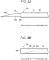
- the distal end portion 20a of the inner needle 20 is drawn into the distal end portion 16a of the outer needle 16 as illustrated in Fig. 3B , and the needle tip 10a of the puncture needle 10 is in a blunt second state.
- the inner needle hub 22 is provided at a proximal end of the inner needle 20 in order to operate the inner needle assembly 14.
- the inner needle hub 22 includes a needle holding portion 24 joined to the inner needle 20, and a slider 26 attached to the needle holding portion 24.
- the needle holding portion 24 of the inner needle hub 22 is disposed inside the cavity 18a of the outer needle hub 18, and slides in the axial direction inside the cavity 18a.
- the outer needle hub 18 and the inner needle hub 22 constitute a switching mechanism 23 that switches the needle tip 10a of the puncture needle 10 between the sharp first state and the blunt second state. Details of the switching mechanism 23 will be described below.
- a connecting portion 28 for holding the outer needle 16 is formed in the vicinity of a distal end of the outer needle hub 18.
- the connecting portion 28 is formed in a funnel shape in which an outer dimension gradually increases from the distal end side toward the proximal end side.
- An outer needle hub body 30 formed in a tubular shape having a rectangular cross section is formed on a proximal end side of the connecting portion 28.
- the outer needle hub body 30 is formed to be long in the axial direction. In the outer needle hub body 30, the cavity 18a extends in the axial direction while maintaining a constant width.
- a guide groove 32 is formed in an upper end portion 30a of the outer needle hub body 30.
- the guide groove 32 is formed to penetrate the upper end portion 30a of the outer needle hub body 30 in a thickness direction (a vertical direction, which is a direction perpendicular to a paper surface in Fig. 4A ), and the cavity 18a opens to the upper end portion 30a through the guide groove 32.
- the guide groove 32 extends in the axial direction, and extends to a proximal end of the outer needle hub body 30. Stopper projections 60 and 62 of the needle holding portion 24 described later slide in contact with the guide groove 32.
- the guide groove 32 is provided with a first recess 34, a second recess 36, a first convex portion 38, and a second convex portion 40. These structures constitute a part of a lock mechanism 25 that positions the needle tip 10a in the first state of Fig. 3A or the second state of Fig. 3B .
- the first recess 34 is formed so as to be recessed toward an outside of the guide groove 32, and a pair of the first recesses is provided on both side portions of the guide groove 32.
- the first recess 34 is formed in a semicircular shape, and step portions 34a perpendicular to the axial direction are formed at end portions on the proximal end side and the distal end side in order to fix the needle holding portion 24 (see Fig. 10B ).
- the second recess 36 is formed on the proximal end side of the first recess 34.
- the second recess 36 is formed in a semicircular shape similar to that of the first recess 34, and a pair of the second recesses is provided on both side portions of the guide groove 32.
- Step portions 36a perpendicular to the axial direction are formed at end portions on the proximal end side and the distal end side of the second recess 36.
- the first recess 34, the second recess 36, and stopper projections 60 and 62 (see Fig. 5B ) to be described later constitute the lock mechanism 25 that fixes the puncture needle 10 between the first state and the second state.
- the guide groove 32 between the first recess 34 and the second recess 36 is provided with a pair of first convex portions 38 protruding inward in the width direction from both side portions of the guide groove 32.
- Each of the first convex portions 38 has a top portion 38a formed at an intermediate position in the axial direction between the first recess 34 and the second recess 36.
- An inclined surface 38b is formed between the top portion 38a and the first recess 34.
- the inclined surface 38b is inclined such that a width of the guide groove 32 increases from the top portion 38a toward the first recess 34.
- an inclined surface 38c is formed between the top portion 38a and the second recess 36.
- the inclined surface 38c is inclined such that the width of the guide groove 32 increases from the top portion 38a toward the second recess 36.
- the guide groove 32 on a proximal end side of the second recess 36 is formed with second convex portions 40 protruding inward in the width direction from both side portions of the guide groove 32.
- Each of the second convex portions 40 has a top portion 40a.
- An inclined surface 40b is formed between the top portion 40a and the second recess 36. The inclined surface 40b is inclined such that the width of the guide groove 32 increases from the top portion 40a toward the second recess 36.
- a pair of guide plates 42 is provided in an upper portion of the outer needle hub body 30 so as to protrude upward.
- the guide plates 42 are provided near both side portions of the outer needle hub body 30 so as to sandwich the guide groove 32 from the width direction.
- Each of the guide plates 42 extends to the proximal end in the axial direction.
- the slider 26 of the inner needle hub 22 is disposed between the guide plates 42.
- the guide plate 42 guides the movement of the slider 26 in the axial direction.
- a proximal end portion of the guide plate 42 is provided with a bridge portion 44 that connects the guide plates 42 on both sides. The bridge portion 44 protrudes upward, and the inner needle hub 22 can be inserted from the proximal end side of the outer needle hub body 30 through a gap in a lower portion of the bridge portion.
- the inner needle hub 22 constituting another part of the switching mechanism 23 will be described.
- the inner needle hub 22 is a member joined to the proximal end of the inner needle 20, and is formed of a hard resin such as polycarbonate.
- the inner needle hub 22 includes the needle holding portion 24 that can be inserted into the guide groove 32 of the outer needle hub body 30 and the slider 26 provided above the needle holding portion 24.
- the needle holding portion 24 is a member connected to the inner needle 20.
- the needle holding portion 24 includes an inner needle connection portion 46 and a needle holding body portion 47.
- the inner needle connection portion 46 to which the inner needle 20 is connected is formed on the distal end side of the needle holding portion 24.
- the inner needle connection portion 46 is formed in a tapered shape such that the width decreases toward the distal end.
- the needle holding body portion 47 linearly extending toward the proximal end side with a constant width is integrally formed with the inner needle connection portion 46.
- a width of the needle holding body portion 47 is formed to be substantially the same as a width of the cavity 18a of the outer needle hub body 30, and it can slide in the cavity 18a in the axial direction.
- the needle holding portion 24 has a rectangular cross section, and a first arm 50 and a second arm 52 are provided to protrude upward from an upper end portion 24a thereof.
- the first arm 50 and the second arm 52 are formed to protrude in a wall shape above the needle holding portion 24, and are separated from the needle holding portion 24 by notch portions 54.
- the first arm 50 is joined to the needle holding portion 24 through a support portion 56 provided on the distal end side of the needle holding portion 24 and extends toward the proximal end side.
- the first arm 50 is inclined so as to approach one side portion 24b from the support portion 56 toward the proximal end side.
- the stopper projection 60 protruding laterally is formed at a proximal end of the first arm 50.
- the second arm 52 is joined to the needle holding portion 24 through a support portion 58 provided on the proximal end side of the needle holding portion 24.
- the second arm 52 extends toward a distal end side from the support portion 58 at a central portion in the width direction of the needle holding portion 24.
- the second arm 52 is inclined so as to approach the other side portion 24c from the support portion 58 toward the distal end side.
- the stopper projection 62 protruding laterally is formed at a distal end of the second arm 52.
- the stopper projection 60 of the first arm 50 and the stopper projection 62 of the second arm 52 are formed at the same position in the axial direction of the needle holding portion 24.
- a separation distance in the width direction between the stopper projection 60 of the first arm 50 and the stopper projection 62 of the second arm 52 is formed to be larger than a gap in the width direction of the guide groove 32 of the outer needle hub body 30. Therefore, when the needle holding portion 24 is inserted into the outer needle hub body 30, the stopper projection 60 and the stopper projection 62 abut on the guide groove 32.
- the stopper projection 60 is pressed against the guide groove 32 by an elastic restoring force of the first arm 50, and the stopper projection 62 is pressed against the guide groove 32 by an elastic restoring force of the second arm 52.
- a rectangular attachment hole 64 elongated in the axial direction is formed in a central portion (between the first arm 50 and the second arm 52) of the upper end portion 24a of the needle holding portion 24.
- An attachment projection 66 of the slider 26 illustrated in Fig. 6A is inserted into the attachment hole 64.
- the slider 26 is a member that is disposed between the pair of guide plates 42 on the upper portion of the outer needle hub body 30 and slides, and is displaced by receiving an operating force of the user.
- the slider 26 is disposed between the guide plates 42.
- an anti-slip rib structure 70 is formed on an upper portion of the slider 26.
- a pair of side wall portions 72 is formed to protrude from both side portions of a bottom portion 26b of the slider 26.
- a release projection 74 which abuts on the stopper projection 60 or 62 (see Fig. 5B ) is formed so as to protrude inward in the width direction.
- Each release projection 74 is provided with a tapered portion 76 including inclined surfaces 76a and 76b and accommodating the stopper projection 60 or 62.
- the attachment projection 66 protrudes from a central portion of the bottom portion 26b of the slider 26.
- the attachment projection 66 is a projection to be inserted into the attachment hole 64 of the needle holding portion 24.
- an anchor portion 68 protruding wider than the attachment hole 64 is formed at a distal end of the attachment projection 66 in order to prevent the attachment projection 66 from falling off from the attachment hole 64.
- the attachment projection 66 of the slider 26 is formed to have a shorter axial length than the attachment hole 64 of the needle holding portion 24, and the slider 26 is provided with gap that can be displaced by a predetermined range in the axial direction with respect to the needle holding portion 24 in a state of being attached to the needle holding portion 24.
- the inclined surfaces 76a and 76b of the release projection 74 in Fig. 6A can displace the stopper projections 60 and 62 of the needle holding portion 24 inward, and can release the engagement state with the first recess 34 (or the second recess 36) of the guide groove 32.
- the puncture needle 10 is provided in a state where the inner needle assembly 14 is inserted into the outer needle assembly 12 as illustrated in Fig. 1 .
- the distal end portion 20a of the inner needle 20 is in the second state of being accommodated on the proximal end side rather than the distal end portion 16a of the outer needle 16 (blunt needle).
- the stopper projection 60 and the stopper projection 62 of the needle holding portion 24 are engaged with the second recesses 36 of the guide groove 32 of the outer needle hub body 30.
- the stopper projection 60 is pressed against the one second recess 36 by a resilient force of the first arm 50, and the stopper projection 62 is pressed against the other second recess 36 by a resilient force of the second arm 52. Therefore, the position of the needle holding portion 24 in the axial direction is fixed to a second position by the stopper projections 60 and 62 and the second recesses 36. That is, the stopper projections 60 and 62, the first arm 50, the second arm 52, and the second recesses 36 constitute the lock mechanism 25 at the second position.
- the user first performs an operation of protruding the distal end portion 20a of the inner needle 20 from the distal end portion 16a of the outer needle 16. As illustrated in Fig. 7B , this operation is performed when the user holds the outer needle hub body 30 with one hand, puts the thumb on the slider 26, and moves the slider 26 forward toward the distal end.
- a distal end edge of the attachment projection 66 of the slider 26 abuts on the distal end of the attachment hole 64, and the needle holding portion 24 advances toward the distal end together with the slider 26.
- the stopper projections 60 and 62 are displaced in the axial direction while sliding on the inclined surfaces 38b and 38c of the first convex portions 38 of the guide groove 32. Note that, when the thumb is released from the slider 26 before exceeding the top portions 38a of the first convex portions 38, the stopper projection 60 biased by the first arm 50 and the stopper projection 62 biased by the second arm 52 slide toward the second recesses 36 along the inclined surfaces 38c, and the needle holding portion 24 retreats to the proximal end side. Then, when the stopper projections 60 and 62 are engaged with the second recesses 36, the needle holding portion 24 stops.
- the sharp distal end portion 20a protrudes from the distal end portion 16a of the outer needle 16.
- the slider 26 comes into contact with the distal end side of the guide groove 32 of the outer needle hub body 30 and stops at the first position.
- the stopper projections 60 and 62 are engaged with the first recesses 34 in a state of being pressed by the resilient forces of the first arm 50 and the second arm 52.
- flat surfaces perpendicular to the axial direction are provided at the distal end and the proximal end of the first recesses 34, and flat surfaces perpendicular to the axial direction are also formed on the proximal end sides of the stopper projections 60 and 62.
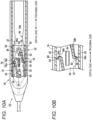
- the stopper projections 60 and 62 are not detached from the first recesses 34. Therefore, even if a load in the axial direction acts on the inner needle 20, the needle holding portion 24 is not displaced from the first position and is held at the first position. At the first position, the stopper projections 60 and 62, the first arm 50, the second arm 52, and the first recesses 34 constitute the lock mechanism 25.
- the user removes the thumb from the slider 26 and punctures the skin 100 of the patient (living body) with the needle tip 10a of the puncture needle 10 as illustrated in Fig. 11A .
- the user operates the slider 26 to switch the needle tip 10a between the first state (sharp) and the second state (blunt). That is, when the slider 26 is pulled toward the proximal end side, the release projections 74 of the slider 26 move toward the proximal end side from the state illustrated in Fig. 10A , and the inclined surfaces 76a on the distal end side of the release projections 74 abut on the stopper projections 60 and 62.
- the needle holding portion 24 moves toward the proximal end side, and stops at the second position where the stopper projections 60 and 62 are engaged with the second recesses 36 as illustrated in Fig. 7A .
- the distal end portion 20a of the inner needle 20 is pulled into the proximal end side of the distal end portion 16a of the outer needle 16, and the needle tip 10a of the puncture needle 10 is switched to the second state (blunt).
- the stopper projections 60 and 62 are engaged with the second recesses 36, light vibration is transmitted to the user's hand as a click feeling.
- the user can recognize that the needle tip 10a has been switched to the second state (blunt).
- the stopper projections 60 and 62 abut on the inclined surfaces 38b and 38c of the first convex portions 38 of the guide groove 32 while being pressed. Therefore, the thrust toward the first position acts on the needle holding portion 24 until the stopper projections 60 and 62 exceed the top portions 38a. Furthermore, after the stopper projections 60 and 62 move to the proximal end side beyond the top portions 38a, a thrust toward the second position acts. Therefore, since the needle holding portion 24 stops at only one of the first position and the second position, even in a state where the state of the needle tip 10a of the puncture needle 10 cannot be visually recognized, the user can easily confirm whether the needle tip 10a is sharp or blunt.
- the user advances the puncture needle 10 to the target site of the living tissue while switching the needle tip 10a of the puncture needle 10 between the first state (sharp) and the second state (blunt).
- the user inserts an indwelling instrument 80 holding the implanted body 90 (for example, collagen fibers and the like) at the distal end from the proximal end portion of the outer needle assembly 12.
- implanted body 90 for example, collagen fibers and the like
- the user causes the distal end of the indwelling instrument 80 to protrude from the distal end portion 16a of the outer needle 16 of the outer needle assembly 12, and pulls out the outer needle assembly 12 from the skin 100 of the living body together with the indwelling instrument 80 as illustrated in Fig. 13B .
- the implantation of the implanted body 90 into the living tissue is completed.
- the distal end portion 20a of the inner needle 20 is a blunt needle formed in a spherical shape, and the distal end portion 16a of the outer needle 16 has a sharp cutting edge obliquely cut off with respect to the axial direction.
- a state in which the distal end portion 20a of the inner needle 20 protrudes more than the distal end portion 16a of the outer needle 16 as illustrated in Fig. 14B is the second state (blunt), and a state in which the distal end portion 20a of the inner needle 20 is pulled toward the proximal end side than the distal end portion 16a of the outer needle 16 is the first state (sharp) as illustrated in Fig. 14A .
- a spaced portion 16c is formed between the inner needle 20 and a blade edge of the distal end portion 16a of the outer needle 16, and when a blood vessel, a nerve, or the like enters the space, these tissues may be damaged by the sharp blade edge. Therefore, in the present modified example, as illustrated in Fig. 15 , the spaced portion 16c (see Fig. 14B ) may be minimized by providing a backcut portion 16d in the vicinity of the blade edge of the distal end portion 16a of the outer needle 16.
- the puncture needle 10 of the present embodiment has the following effects.
- the puncture needle 10 of the present embodiment includes the outer needle 16 having the lumen 16b penetrating in the axial direction, the outer needle hub 18 joined to the proximal end portion of the outer needle 16, the inner needle 20 inserted into the lumen 16b of the outer needle 16 via the outer needle hub 18, the switching mechanism 23 capable of switching between a first state in which the inner needle 20 is displaced in the axial direction and the needle tip 10a is sharp and a second state in which the needle tip 10a is blunt, and the lock mechanism 25 that maintains the position of the inner needle 20.
- the needle tip 10a can be switched between the sharp first state and the blunt second state. Therefore, it is possible to advance in the living tissue while preventing damage to blood vessels, nerves, and the like. Furthermore, since the lock mechanism 25 is provided, the needle tip 10a is not switched from the first state to the second state in the middle of puncture, so that the user can concentrate on the puncture operation.
- the distal end portion 20a of the inner needle 20 may be sharp, and the distal end portion 16a of the outer needle 16 may be blunt. In this case, a state in which the distal end portion 20a of the inner needle 20 protrudes more than the distal end portion 16a of the outer needle 16 becomes the sharp first state.
- the distal end portion 16a of the outer needle 16 may be sharp, and the distal end portion 20a of the inner needle 20 may be blunt.
- a state in which the distal end portion 20a of the inner needle 20 is pulled toward the proximal end side of the distal end portion 16a of the outer needle 16 is the sharp first state.
- the backcut portion 16d may be provided at the distal end portion 16a of the outer needle 16. This can prevent damage to tissues such as blood vessels and nerves.
- the puncture needle 10 described above may further include the inner needle hub 22 provided at the proximal end of the inner needle 20 and inserted into the outer needle hub 18, and the switching mechanism 23 may include the guide groove 32 that is provided in the outer needle hub 18 and guides the inner needle hub 22 in the axial direction, the first recess 34 that is provided in the guide groove 32 and positions the inner needle hub 22 at the first position, the second recess 36 that is provided on the proximal end side of the first recess 34 and positions the inner needle hub 22 at the second position, and the stopper projections 60 and 62 provided in the inner needle hub 22 and protruding from the inner needle hub 22 toward the guide groove 32 while being elastically biased, and engaging with the first recesses 34 and the second recesses 36.
- the stopper projections 60 and 62 are engaged with the first recesses 34 or the second recesses 36, so that the needle tip 10a can be switched between the first state and the second state. Furthermore, since the user can recognize the switching between the first state and the second state without confirming the hand by the click feeling when the stopper projections 60 and 62 are engaged with the first recesses 34 or the second recesses 36, the user can easily handle the puncture needle 10.
- the inner needle hub 22 may include the slider 26 provided in the inner needle hub 22, and the slider 26 may be configured to release the engagement between the stopper projections 60 and 62 and the first recesses 34 or the second recesses 36 by pulling the stopper projections 60 and 62 inward. According to this configuration, the user can easily move the inner needle hub 22 through the operation of the slider 26.
- the first recesses 34 and the second recesses 36 may be provided with the step portions 34a and 36a that prevent detachment of the stopper projections 60 and 62. According to this configuration, even if a load in the axial direction acts on the inner needle 20, the movement of the inner needle hub 22 can be prevented, and the first state or the second state can be maintained.
- the guide groove 32 may be provided with inclined surfaces 38b, 38c, and 40b that guide the stopper projections 60 and 62 to the first recesses 34 or the second recesses 36. According to this configuration, since the inner needle hub 22 is spontaneously displaced to the first position or the second position, it is possible to prevent the inner needle hub 22 from stopping in an unknown state in the middle of the first state or the second state of the needle tip 10a of the puncture needle 10, so that the handleability of the puncture needle 10 is improved.
Landscapes
- Health & Medical Sciences (AREA)
- Life Sciences & Earth Sciences (AREA)
- Surgery (AREA)
- Public Health (AREA)
- Animal Behavior & Ethology (AREA)
- Engineering & Computer Science (AREA)
- Biomedical Technology (AREA)
- Heart & Thoracic Surgery (AREA)
- Veterinary Medicine (AREA)
- General Health & Medical Sciences (AREA)
- Nuclear Medicine, Radiotherapy & Molecular Imaging (AREA)
- Molecular Biology (AREA)
- Pathology (AREA)
- Medical Informatics (AREA)
- Vascular Medicine (AREA)
- Anesthesiology (AREA)
- Hematology (AREA)
- Infusion, Injection, And Reservoir Apparatuses (AREA)
Abstract
Description
- The present invention relates to a puncture needle for forming a long hole in a living tissue.
- Conventionally, various medical instruments for forming a long hole in a living tissue have been proposed. For example,
US 10,702,263 -
JP 3227041 U -
JP 2020-127607 A - The above instrument has a sharp or blunt-shaped needle tip to be punctured into a living tissue at a distal end of a long tubular puncture member.
- In a case where the puncture needle penetrates the skin or a fiberized hard tissue, if the tip is sharp, puncture becomes easy and damage to the surrounding tissue is reduced. On the other hand, in a case where the puncture needle penetrates a soft tissue such as an adipose tissue, it is preferable that the tip is blunt from the viewpoint of preventing damage to peripheral blood vessels, nerves, and the like.
- Therefore, an object of one embodiment is to provide a puncture needle capable of suppressing damage to a living tissue at the time of puncturing.
- One aspect of the following disclosure is a puncture needle including: an outer needle including a lumen penetrating in an axial direction; an outer needle hub joined to a proximal end portion of the outer needle; an inner needle inserted into the lumen of the outer needle via the outer needle hub; a switching mechanism capable of switching between a first state in which a needle tip is sharp and a second state in which the needle tip is blunt by displacing the inner needle in the axial direction; and a lock mechanism that maintains a position of the inner needle.
- According to the puncture needle of the above aspect, it is possible to suppress damage to a living tissue at the time of puncturing.
-
-
Fig. 1 is a perspective view of a puncture needle according to a first embodiment. -
Fig. 2 is a perspective view of a state in which an outer needle assembly and an inner needle assembly of the puncture needle ofFig. 1 are separated. -
Fig. 3A is an enlarged view of a needle tip of the puncture needle ofFig. 1 in a first state (sharp), andFig. 3B is an enlarged view of the needle tip of the puncture needle ofFig. 1 in a second state (blunt). -
Fig. 4A is a top view of an outer needle hub, andFig. 4B is a cross-sectional view of the outer needle hub taken along line IVB-IVB inFig. 4A . -
Fig. 5A is a perspective view of an inner needle hub, andFig. 5B is a perspective view of a needle holding portion. -
Fig. 6A is a perspective view of a bottom surface side of a slider, andFig. 6B is a cross-sectional view of the inner needle hub taken along line IVB-IVB inFig. 5A . -
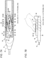
Fig. 7A is a cross-sectional view illustrating an arrangement relationship of the inner needle hub and the outer needle hub in an initial state, andFig. 7B is an explanatory view illustrating an operation of protruding the inner needle hub from the initial state. -
Fig. 8A is a cross-sectional view of a state in which the slider is advanced toward a distal end side from the state ofFig. 7A to release engagement between a stopper projection and a second recess, andFig. 8B is a cross-sectional view of a state in which the slider is further advanced toward the distal end side from the state ofFig. 8A . -
Fig. 9A is a cross-sectional view illustrating a state in which the inner needle hub moves to a first position and the stopper projection engages with a first recess, andFig. 9B is a side view illustrating a position of the slider inFig. 9A . -
Fig. 10A is a cross-sectional view illustrating an arrangement relationship between the inner needle hub and the outer needle hub at the first position, andFig. 10B is an enlarged cross-sectional view illustrating an engagement state of the stopper projection and the first recess inFig. 10A . -
Fig. 11A is an explanatory diagram illustrating an operation of puncturing a living tissue with the puncture needle ofFig. 1 , andFig. 11B is an explanatory view illustrating an operation of detaching the inner needle after the puncture of the puncture needle is completed. -
Fig. 12 is an explanatory view illustrating an operation of attaching an indwelling instrument to the outer needle assembly of the puncture needle ofFig. 1 . -
Fig. 13A is an explanatory view illustrating an operation of feeding an implanted body to a target site, andFig. 13B is an explanatory view illustrating an operation of withdrawing the indwelling instrument together with the outer needle of the puncture needle while leaving the implanted body in the living tissue. -
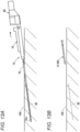
Fig. 14A is an enlarged view of a needle tip of a puncture needle according to a modified example of the embodiment in a first state (sharp), andFig. 14B is an enlarged view of the needle tip of the puncture needle inFig. 14A in a second state (blunt). -
Fig. 15 is an enlarged view illustrating an example in which a backcut portion is provided in the puncture needle ofFig. 14B . - Hereinafter, a preferred embodiment of a
puncture needle 10 will be described in detail with reference to the accompanying drawings. - As illustrated in
Figs. 1 and2 , thepuncture needle 10 according to the embodiment includes anouter needle assembly 12 and aninner needle assembly 14. Theinner needle assembly 14 is disposed to be insertable into and removable from theouter needle assembly 12 from a proximal end side of theouter needle assembly 12. Thepuncture needle 10 is used by puncturing from a skin 100 (seeFig. 11A ) of a patient (living body) to a target site in a living tissue in a state where theinner needle assembly 14 is attached. After completion of puncture, theinner needle assembly 14 is removed from thepuncture needle 10, and theouter needle assembly 12 is used for introduction of an implanted body 90 (seeFig. 13A ) such as an artificial blood vessel and collagen fibers. - As illustrated in
Fig. 2 , theouter needle assembly 12 includes an elongatedouter needle 16. Theouter needle 16 is a cylindrical member made of a metal such as stainless steel, an aluminum alloy, or a titanium alloy, a hard resin, or the like. Adistal end portion 16a of theouter needle 16 is formed substantially perpendicular to an axial direction and is a blunt needle. Inside theouter needle 16, alumen 16b is formed penetrating theouter needle 16 in the axial direction. - An
outer needle hub 18 is connected to a proximal end of theouter needle 16. Theouter needle hub 18 is a tubular member made of a resin such as polycarbonate, for example, and is formed to have an outer diameter dimension that allows a user to easily grip and operate the outer needle hub by hand. Acavity 18a extending in the axial direction is formed inside theouter needle hub 18. A distal end side of thecavity 18a communicates with thelumen 16b of theouter needle 16, and a proximal end side of thecavity 18a opens at a proximal end portion of theouter needle hub 18. Thecavity 18a extends in the axial direction and guides a sliding operation of aninner needle hub 22 described later. Details of a structure of theouter needle hub 18 will be described later. - On the other hand, the
inner needle assembly 14 includes an elongatedinner needle 20. Theinner needle 20 is an elongated cylindrical member, and is formed of, for example, metal such as stainless steel. Theinner needle 20 is formed to have an outer diameter smaller than that of thelumen 16b of theouter needle 16, and can be inserted into thelumen 16b. Theinner needle 20 is a hollow needle in which alumen 20b is formed. Note that theinner needle 20 may be a solid needle having a solid inside. Adistal end portion 20a of theinner needle 20 is formed to be sharp. - As illustrated in
Fig. 3A , thedistal end portion 20a is formed with a blade surface cut obliquely with respect to the axial direction, and a sharp blade edge is formed at a distal end of the blade surface. Theinner needle 20 is formed to be longer than theouter needle 16. When theinner needle assembly 14 inFig. 1 is pushed toward the distal end side of theouter needle assembly 12, thedistal end portion 20a of theinner needle 20 protrudes from thedistal end portion 16a of theouter needle 16 as illustrated inFig. 3A , and aneedle tip 10a of thepuncture needle 10 enters a sharp first state.
Furthermore, when theinner needle assembly 14 inFig. 1 is moved to the proximal end side of theouter needle assembly 12, thedistal end portion 20a of theinner needle 20 is drawn into thedistal end portion 16a of theouter needle 16 as illustrated inFig. 3B , and theneedle tip 10a of thepuncture needle 10 is in a blunt second state. - As illustrated in
Fig. 2 , theinner needle hub 22 is provided at a proximal end of theinner needle 20 in order to operate theinner needle assembly 14. Theinner needle hub 22 includes aneedle holding portion 24 joined to theinner needle 20, and aslider 26 attached to theneedle holding portion 24. Theneedle holding portion 24 of theinner needle hub 22 is disposed inside thecavity 18a of theouter needle hub 18, and slides in the axial direction inside thecavity 18a. - The
outer needle hub 18 and theinner needle hub 22 constitute aswitching mechanism 23 that switches theneedle tip 10a of thepuncture needle 10 between the sharp first state and the blunt second state. Details of theswitching mechanism 23 will be described below. - As illustrated in
Figs. 4A and 4B , a connectingportion 28 for holding theouter needle 16 is formed in the vicinity of a distal end of theouter needle hub 18. The connectingportion 28 is formed in a funnel shape in which an outer dimension gradually increases from the distal end side toward the proximal end side. An outerneedle hub body 30 formed in a tubular shape having a rectangular cross section is formed on a proximal end side of the connectingportion 28. The outerneedle hub body 30 is formed to be long in the axial direction. In the outerneedle hub body 30, thecavity 18a extends in the axial direction while maintaining a constant width. - As illustrated in
Fig. 4A , aguide groove 32 is formed in anupper end portion 30a of the outerneedle hub body 30. As illustrated inFig. 4A , theguide groove 32 is formed to penetrate theupper end portion 30a of the outerneedle hub body 30 in a thickness direction (a vertical direction, which is a direction perpendicular to a paper surface inFig. 4A ), and thecavity 18a opens to theupper end portion 30a through theguide groove 32. As illustrated inFig. 4B , theguide groove 32 extends in the axial direction, and extends to a proximal end of the outerneedle hub body 30.Stopper projections needle holding portion 24 described later slide in contact with theguide groove 32. - The
guide groove 32 is provided with afirst recess 34, asecond recess 36, a firstconvex portion 38, and a secondconvex portion 40. These structures constitute a part of alock mechanism 25 that positions theneedle tip 10a in the first state ofFig. 3A or the second state ofFig. 3B . Thefirst recess 34 is formed so as to be recessed toward an outside of theguide groove 32, and a pair of the first recesses is provided on both side portions of theguide groove 32. Thefirst recess 34 is formed in a semicircular shape, andstep portions 34a perpendicular to the axial direction are formed at end portions on the proximal end side and the distal end side in order to fix the needle holding portion 24 (seeFig. 10B ). - The
second recess 36 is formed on the proximal end side of thefirst recess 34. Thesecond recess 36 is formed in a semicircular shape similar to that of thefirst recess 34, and a pair of the second recesses is provided on both side portions of theguide groove 32.Step portions 36a perpendicular to the axial direction are formed at end portions on the proximal end side and the distal end side of thesecond recess 36. Thefirst recess 34, thesecond recess 36, andstopper projections 60 and 62 (seeFig. 5B ) to be described later constitute thelock mechanism 25 that fixes thepuncture needle 10 between the first state and the second state. - The
guide groove 32 between thefirst recess 34 and thesecond recess 36 is provided with a pair of firstconvex portions 38 protruding inward in the width direction from both side portions of theguide groove 32. Each of the firstconvex portions 38 has atop portion 38a formed at an intermediate position in the axial direction between thefirst recess 34 and thesecond recess 36. Aninclined surface 38b is formed between thetop portion 38a and thefirst recess 34. Theinclined surface 38b is inclined such that a width of theguide groove 32 increases from thetop portion 38a toward thefirst recess 34. Furthermore, aninclined surface 38c is formed between thetop portion 38a and thesecond recess 36. Theinclined surface 38c is inclined such that the width of theguide groove 32 increases from thetop portion 38a toward thesecond recess 36. - The
guide groove 32 on a proximal end side of thesecond recess 36 is formed with secondconvex portions 40 protruding inward in the width direction from both side portions of theguide groove 32. Each of the secondconvex portions 40 has atop portion 40a. Aninclined surface 40b is formed between thetop portion 40a and thesecond recess 36. Theinclined surface 40b is inclined such that the width of theguide groove 32 increases from thetop portion 40a toward thesecond recess 36. - As illustrated in
Figs. 2 and4B , a pair ofguide plates 42 is provided in an upper portion of the outerneedle hub body 30 so as to protrude upward. Theguide plates 42 are provided near both side portions of the outerneedle hub body 30 so as to sandwich theguide groove 32 from the width direction. Each of theguide plates 42 extends to the proximal end in the axial direction. Theslider 26 of theinner needle hub 22 is disposed between theguide plates 42. Theguide plate 42 guides the movement of theslider 26 in the axial direction. A proximal end portion of theguide plate 42 is provided with abridge portion 44 that connects theguide plates 42 on both sides. Thebridge portion 44 protrudes upward, and theinner needle hub 22 can be inserted from the proximal end side of the outerneedle hub body 30 through a gap in a lower portion of the bridge portion. - Next, the
inner needle hub 22 constituting another part of theswitching mechanism 23 will be described. Theinner needle hub 22 is a member joined to the proximal end of theinner needle 20, and is formed of a hard resin such as polycarbonate. As illustrated inFig. 5A , theinner needle hub 22 includes theneedle holding portion 24 that can be inserted into theguide groove 32 of the outerneedle hub body 30 and theslider 26 provided above theneedle holding portion 24. - The
needle holding portion 24 is a member connected to theinner needle 20. Theneedle holding portion 24 includes an innerneedle connection portion 46 and a needle holdingbody portion 47. The innerneedle connection portion 46 to which theinner needle 20 is connected is formed on the distal end side of theneedle holding portion 24. The innerneedle connection portion 46 is formed in a tapered shape such that the width decreases toward the distal end. On a proximal end side of the innerneedle connection portion 46, the needle holdingbody portion 47 linearly extending toward the proximal end side with a constant width is integrally formed with the innerneedle connection portion 46. A width of the needle holdingbody portion 47 is formed to be substantially the same as a width of thecavity 18a of the outerneedle hub body 30, and it can slide in thecavity 18a in the axial direction. - As illustrated in
Fig. 5B , theneedle holding portion 24 has a rectangular cross section, and afirst arm 50 and asecond arm 52 are provided to protrude upward from anupper end portion 24a thereof. Thefirst arm 50 and thesecond arm 52 are formed to protrude in a wall shape above theneedle holding portion 24, and are separated from theneedle holding portion 24 bynotch portions 54. Thefirst arm 50 is joined to theneedle holding portion 24 through asupport portion 56 provided on the distal end side of theneedle holding portion 24 and extends toward the proximal end side. Thefirst arm 50 is inclined so as to approach oneside portion 24b from thesupport portion 56 toward the proximal end side. Thestopper projection 60 protruding laterally is formed at a proximal end of thefirst arm 50. - The
second arm 52 is joined to theneedle holding portion 24 through asupport portion 58 provided on the proximal end side of theneedle holding portion 24. Thesecond arm 52 extends toward a distal end side from thesupport portion 58 at a central portion in the width direction of theneedle holding portion 24. Thesecond arm 52 is inclined so as to approach theother side portion 24c from thesupport portion 58 toward the distal end side. Thestopper projection 62 protruding laterally is formed at a distal end of thesecond arm 52. - The
stopper projection 60 of thefirst arm 50 and thestopper projection 62 of thesecond arm 52 are formed at the same position in the axial direction of theneedle holding portion 24. A separation distance in the width direction between thestopper projection 60 of thefirst arm 50 and thestopper projection 62 of thesecond arm 52 is formed to be larger than a gap in the width direction of theguide groove 32 of the outerneedle hub body 30. Therefore, when theneedle holding portion 24 is inserted into the outerneedle hub body 30, thestopper projection 60 and thestopper projection 62 abut on theguide groove 32. Thestopper projection 60 is pressed against theguide groove 32 by an elastic restoring force of thefirst arm 50, and thestopper projection 62 is pressed against theguide groove 32 by an elastic restoring force of thesecond arm 52. - A
rectangular attachment hole 64 elongated in the axial direction is formed in a central portion (between thefirst arm 50 and the second arm 52) of theupper end portion 24a of theneedle holding portion 24. Anattachment projection 66 of theslider 26 illustrated inFig. 6A is inserted into theattachment hole 64. - As illustrated in
Fig. 1 , theslider 26 is a member that is disposed between the pair ofguide plates 42 on the upper portion of the outerneedle hub body 30 and slides, and is displaced by receiving an operating force of the user. Theslider 26 is disposed between theguide plates 42. As illustrated inFig. 5A , ananti-slip rib structure 70 is formed on an upper portion of theslider 26. - As illustrated in
Fig. 6A , a pair ofside wall portions 72 is formed to protrude from both side portions of abottom portion 26b of theslider 26. On each of theside wall portions 72, arelease projection 74 which abuts on thestopper projection 60 or 62 (seeFig. 5B ) is formed so as to protrude inward in the width direction. Eachrelease projection 74 is provided with a taperedportion 76 includinginclined surfaces stopper projection attachment projection 66 protrudes from a central portion of thebottom portion 26b of theslider 26. - As illustrated in
Fig. 6B , theattachment projection 66 is a projection to be inserted into theattachment hole 64 of theneedle holding portion 24. As illustrated inFig. 6A , ananchor portion 68 protruding wider than theattachment hole 64 is formed at a distal end of theattachment projection 66 in order to prevent theattachment projection 66 from falling off from theattachment hole 64. As illustrated inFig. 6B , theattachment projection 66 of theslider 26 is formed to have a shorter axial length than theattachment hole 64 of theneedle holding portion 24, and theslider 26 is provided with gap that can be displaced by a predetermined range in the axial direction with respect to theneedle holding portion 24 in a state of being attached to theneedle holding portion 24. When theslider 26 is moved with respect to theneedle holding portion 24 using this gap, theinclined surfaces release projection 74 inFig. 6A can displace thestopper projections needle holding portion 24 inward, and can release the engagement state with the first recess 34 (or the second recess 36) of theguide groove 32. - Hereinafter, an operation of the
puncture needle 10 of the present embodiment will be described together with a usage method thereof. - The
puncture needle 10 is provided in a state where theinner needle assembly 14 is inserted into theouter needle assembly 12 as illustrated inFig. 1 . However, in order to prevent erroneous puncture of theneedle tip 10a during storage and conveyance, in the initial state, as illustrated inFig. 3B , thedistal end portion 20a of theinner needle 20 is in the second state of being accommodated on the proximal end side rather than thedistal end portion 16a of the outer needle 16 (blunt needle). - In the second state, as illustrated in
Fig. 7A , thestopper projection 60 and thestopper projection 62 of theneedle holding portion 24 are engaged with thesecond recesses 36 of theguide groove 32 of the outerneedle hub body 30. Thestopper projection 60 is pressed against the onesecond recess 36 by a resilient force of thefirst arm 50, and thestopper projection 62 is pressed against the othersecond recess 36 by a resilient force of thesecond arm 52. Therefore, the position of theneedle holding portion 24 in the axial direction is fixed to a second position by thestopper projections stopper projections first arm 50, thesecond arm 52, and thesecond recesses 36 constitute thelock mechanism 25 at the second position. - The user first performs an operation of protruding the
distal end portion 20a of theinner needle 20 from thedistal end portion 16a of theouter needle 16. As illustrated inFig. 7B , this operation is performed when the user holds the outerneedle hub body 30 with one hand, puts the thumb on theslider 26, and moves theslider 26 forward toward the distal end. - As illustrated in
Fig. 8A , when the user advances theslider 26 toward the distal end, theslider 26 is displaced toward the distal end side with respect to theneedle holding portion 24 due to axial play between theslider 26 and theneedle holding portion 24. As a result, thetapered portions 76 of therelease projections 74 are displaced toward the distal end side, and theinclined surfaces 76b on a rear end side abut on thestopper projections slider 26 further advances, thestopper projections inclined surfaces 76b. As a result, the engagement state between thestopper projections needle holding portion 24 can be displaced in the axial direction. - As illustrated in
Fig. 8B , a distal end edge of theattachment projection 66 of theslider 26 abuts on the distal end of theattachment hole 64, and theneedle holding portion 24 advances toward the distal end together with theslider 26. Thestopper projections inclined surfaces convex portions 38 of theguide groove 32. Note that, when the thumb is released from theslider 26 before exceeding thetop portions 38a of the firstconvex portions 38, thestopper projection 60 biased by thefirst arm 50 and thestopper projection 62 biased by thesecond arm 52 slide toward thesecond recesses 36 along theinclined surfaces 38c, and theneedle holding portion 24 retreats to the proximal end side. Then, when thestopper projections needle holding portion 24 stops. - As illustrated in
Fig. 9A , when theneedle holding portion 24 is advanced toward the distal end through theslider 26, thestopper projections top portions 38a of the firstconvex portions 38 of theguide groove 32 and move to the distal end side, and are displaced to a first position engaged with the first recesses 34. Thereafter, when thestopper projections first recesses 34, vibration (impact) is generated, and the vibration is transmitted to the user's hand as a click feeling. The user can recognize that theneedle tip 10a is switched to the first state (sharp) from the click feeling of the hand. Therefore, as illustrated inFig. 3A , the sharpdistal end portion 20a protrudes from thedistal end portion 16a of theouter needle 16. As illustrated inFigs. 9A and 9B , theslider 26 comes into contact with the distal end side of theguide groove 32 of the outerneedle hub body 30 and stops at the first position. - Note that, when the
stopper projections top portions 38a of the firstconvex portions 38 and move toward theinclined surfaces 38b, the resilient forces of thefirst arm 50 and thesecond arm 52 act, and thus, thrust toward the first recesses 34 is generated in theslider 26 and theneedle holding portion 24. Therefore, even when the user releases the thumb from theslider 26, theneedle holding portion 24 is spontaneously displaced in the distal direction until thestopper projections - As illustrated in
Fig. 10A , at the first position, thestopper projections first recesses 34 in a state of being pressed by the resilient forces of thefirst arm 50 and thesecond arm 52. As illustrated in an enlarged manner inFig. 10B , flat surfaces perpendicular to the axial direction are provided at the distal end and the proximal end of thefirst recesses 34, and flat surfaces perpendicular to the axial direction are also formed on the proximal end sides of thestopper projections inner needle 20 toward the proximal end side acts on theinner needle 20 by puncturing theskin 100 with the inner needle or the like, thestopper projections inner needle 20, theneedle holding portion 24 is not displaced from the first position and is held at the first position. At the first position, thestopper projections first arm 50, thesecond arm 52, and thefirst recesses 34 constitute thelock mechanism 25. - Thereafter, the user removes the thumb from the
slider 26 and punctures theskin 100 of the patient (living body) with theneedle tip 10a of thepuncture needle 10 as illustrated inFig. 11A . After puncturing a subcutaneous tissue, the user operates theslider 26 to switch theneedle tip 10a between the first state (sharp) and the second state (blunt). That is, when theslider 26 is pulled toward the proximal end side, therelease projections 74 of theslider 26 move toward the proximal end side from the state illustrated inFig. 10A , and theinclined surfaces 76a on the distal end side of therelease projections 74 abut on thestopper projections inclined surfaces 76a move to the proximal end side, thestopper projections stopper projections needle holding portion 24 can move to the proximal end side. - By further sliding the
slider 26 toward the proximal end side, theneedle holding portion 24 moves toward the proximal end side, and stops at the second position where thestopper projections second recesses 36 as illustrated inFig. 7A . As a result, as illustrated inFig. 3B , thedistal end portion 20a of theinner needle 20 is pulled into the proximal end side of thedistal end portion 16a of theouter needle 16, and theneedle tip 10a of thepuncture needle 10 is switched to the second state (blunt). When thestopper projections needle tip 10a of thepuncture needle 10, the user can recognize that theneedle tip 10a has been switched to the second state (blunt). - Note that, in the middle of moving the
needle holding portion 24 from the first position to the second position, thestopper projections inclined surfaces convex portions 38 of theguide groove 32 while being pressed. Therefore, the thrust toward the first position acts on theneedle holding portion 24 until thestopper projections top portions 38a. Furthermore, after thestopper projections top portions 38a, a thrust toward the second position acts. Therefore, since theneedle holding portion 24 stops at only one of the first position and the second position, even in a state where the state of theneedle tip 10a of thepuncture needle 10 cannot be visually recognized, the user can easily confirm whether theneedle tip 10a is sharp or blunt. - The user advances the
puncture needle 10 to the target site of the living tissue while switching theneedle tip 10a of thepuncture needle 10 between the first state (sharp) and the second state (blunt). - As illustrated in
Fig. 11B , after theneedle tip 10a of thepuncture needle 10 reaches the target position, the user pulls out theinner needle assembly 14 from theouter needle assembly 12. - Thereafter, as illustrated in
Fig. 12 , the user inserts anindwelling instrument 80 holding the implanted body 90 (for example, collagen fibers and the like) at the distal end from the proximal end portion of theouter needle assembly 12. - As illustrated in
Fig. 13A , the user causes the distal end of theindwelling instrument 80 to protrude from thedistal end portion 16a of theouter needle 16 of theouter needle assembly 12, and pulls out theouter needle assembly 12 from theskin 100 of the living body together with theindwelling instrument 80 as illustrated inFig. 13B . As a result, the implantation of the implantedbody 90 into the living tissue is completed. - Hereinafter, a modified example of the
puncture needle 10 of the present embodiment will be described. As illustrated inFigs. 14A and 14B , in theneedle tip 10a according to the modified example, thedistal end portion 20a of theinner needle 20 is a blunt needle formed in a spherical shape, and thedistal end portion 16a of theouter needle 16 has a sharp cutting edge obliquely cut off with respect to the axial direction. - In the present modified example, a state in which the
distal end portion 20a of theinner needle 20 protrudes more than thedistal end portion 16a of theouter needle 16 as illustrated inFig. 14B is the second state (blunt), and a state in which thedistal end portion 20a of theinner needle 20 is pulled toward the proximal end side than thedistal end portion 16a of theouter needle 16 is the first state (sharp) as illustrated inFig. 14A . - Note that, in the second state of
Fig. 14B , a spacedportion 16c is formed between theinner needle 20 and a blade edge of thedistal end portion 16a of theouter needle 16, and when a blood vessel, a nerve, or the like enters the space, these tissues may be damaged by the sharp blade edge. Therefore, in the present modified example, as illustrated inFig. 15 , the spacedportion 16c (seeFig. 14B ) may be minimized by providing abackcut portion 16d in the vicinity of the blade edge of thedistal end portion 16a of theouter needle 16. - The
puncture needle 10 of the present embodiment has the following effects. - The
puncture needle 10 of the present embodiment includes theouter needle 16 having thelumen 16b penetrating in the axial direction, theouter needle hub 18 joined to the proximal end portion of theouter needle 16, theinner needle 20 inserted into thelumen 16b of theouter needle 16 via theouter needle hub 18, theswitching mechanism 23 capable of switching between a first state in which theinner needle 20 is displaced in the axial direction and theneedle tip 10a is sharp and a second state in which theneedle tip 10a is blunt, and thelock mechanism 25 that maintains the position of theinner needle 20. - According to the
puncture needle 10, theneedle tip 10a can be switched between the sharp first state and the blunt second state. Therefore, it is possible to advance in the living tissue while preventing damage to blood vessels, nerves, and the like. Furthermore, since thelock mechanism 25 is provided, theneedle tip 10a is not switched from the first state to the second state in the middle of puncture, so that the user can concentrate on the puncture operation. - In the
puncture needle 10 described above, thedistal end portion 20a of theinner needle 20 may be sharp, and thedistal end portion 16a of theouter needle 16 may be blunt. In this case, a state in which thedistal end portion 20a of theinner needle 20 protrudes more than thedistal end portion 16a of theouter needle 16 becomes the sharp first state. - In the
puncture needle 10 described above, thedistal end portion 16a of theouter needle 16 may be sharp, and thedistal end portion 20a of theinner needle 20 may be blunt. In this case, a state in which thedistal end portion 20a of theinner needle 20 is pulled toward the proximal end side of thedistal end portion 16a of theouter needle 16 is the sharp first state. In this case, thebackcut portion 16d may be provided at thedistal end portion 16a of theouter needle 16. This can prevent damage to tissues such as blood vessels and nerves. - The
puncture needle 10 described above may further include theinner needle hub 22 provided at the proximal end of theinner needle 20 and inserted into theouter needle hub 18, and theswitching mechanism 23 may include theguide groove 32 that is provided in theouter needle hub 18 and guides theinner needle hub 22 in the axial direction, thefirst recess 34 that is provided in theguide groove 32 and positions theinner needle hub 22 at the first position, thesecond recess 36 that is provided on the proximal end side of thefirst recess 34 and positions theinner needle hub 22 at the second position, and thestopper projections inner needle hub 22 and protruding from theinner needle hub 22 toward theguide groove 32 while being elastically biased, and engaging with thefirst recesses 34 and the second recesses 36. - According to this configuration, the
stopper projections first recesses 34 or the second recesses 36, so that theneedle tip 10a can be switched between the first state and the second state. Furthermore, since the user can recognize the switching between the first state and the second state without confirming the hand by the click feeling when thestopper projections first recesses 34 or the second recesses 36, the user can easily handle thepuncture needle 10. - In the
puncture needle 10 described above, theinner needle hub 22 may include theslider 26 provided in theinner needle hub 22, and theslider 26 may be configured to release the engagement between thestopper projections first recesses 34 or thesecond recesses 36 by pulling thestopper projections inner needle hub 22 through the operation of theslider 26. - In the
puncture needle 10 described above, thefirst recesses 34 and thesecond recesses 36 may be provided with thestep portions stopper projections inner needle 20, the movement of theinner needle hub 22 can be prevented, and the first state or the second state can be maintained. - In the
puncture needle 10 described above, theguide groove 32 may be provided withinclined surfaces stopper projections first recesses 34 or the second recesses 36. According to this configuration, since theinner needle hub 22 is spontaneously displaced to the first position or the second position, it is possible to prevent theinner needle hub 22 from stopping in an unknown state in the middle of the first state or the second state of theneedle tip 10a of thepuncture needle 10, so that the handleability of thepuncture needle 10 is improved. - Although the present invention has been described above with reference to preferred embodiments, the present invention is not limited to the above embodiments, and it goes without saying that various modifications can be made without departing from the gist of the present invention.
Claims (8)
- A puncture needle comprising:an outer needle including a lumen penetrating in an axial direction;an outer needle hub joined to a proximal end portion of the outer needle;an inner needle inserted into the lumen of the outer needle via the outer needle hub;a switching mechanism capable of switching between a first state in which a needle tip is sharp and a second state in which the needle tip is blunt by displacing the inner needle in the axial direction; anda lock mechanism that maintains a position of the inner needle.
- The puncture needle according to claim 1, wherein a distal end of the inner needle is sharp, and a distal end of the outer needle is blunt.
- The puncture needle according to claim 1, wherein a distal end of the outer needle is sharp, and a distal end of the inner needle is blunt.
- The puncture needle according to claim 3, wherein a backcut portion is formed at a distal end of the outer needle.
- The puncture needle according to any one of claims 1 to 4, further comprising an inner needle hub provided at a proximal end of the inner needle and inserted into the outer needle hub, wherein the switching mechanism includes:a guide groove that is provided in the outer needle hub and guides the inner needle hub in the axial direction;a first recess that is provided in the guide groove and positions the inner needle hub at a first position, and a second recess that is provided on a proximal end side of the first recess and positions the inner needle hub at a second position; anda stopper projection provided on the inner needle hub, protruding from the inner needle hub toward the guide groove while being elastically biased, and engaging with the first recess and the second recess.
- The puncture needle according to claim 5, wherein the inner needle hub includes a slider provided on the inner needle hub, and the slider releases engagement between the stopper projection and the first recess or the second recess by pulling the stopper projection inward.
- The puncture needle according to claim 5 or 6, wherein the first recess and the second recess are provided with a step portion that prevents detachment of the stopper projection.
- The puncture needle according to any one of claims 5 to 7, wherein the guide groove is provided with an inclined surface that guides the stopper projection to the first recess or the second recess.
Applications Claiming Priority (2)
| Application Number | Priority Date | Filing Date | Title |
|---|---|---|---|
| JP2021006129 | 2021-01-19 | ||
| PCT/JP2022/001260 WO2022158405A1 (en) | 2021-01-19 | 2022-01-17 | Puncture needle |
Publications (2)
| Publication Number | Publication Date |
|---|---|
| EP4272784A1 true EP4272784A1 (en) | 2023-11-08 |
| EP4272784A4 EP4272784A4 (en) | 2024-06-12 |
Family
ID=82548994
Family Applications (1)
| Application Number | Title | Priority Date | Filing Date |
|---|---|---|---|
| EP22742527.9A Pending EP4272784A4 (en) | 2021-01-19 | 2022-01-17 | PUNCTURE NEEDLE |
Country Status (4)
| Country | Link |
|---|---|
| US (1) | US12508051B2 (en) |
| EP (1) | EP4272784A4 (en) |
| JP (1) | JP7720332B2 (en) |
| WO (1) | WO2022158405A1 (en) |
Families Citing this family (2)
| Publication number | Priority date | Publication date | Assignee | Title |
|---|---|---|---|---|
| JP2024125645A (en) | 2023-03-06 | 2024-09-19 | 富士フイルム株式会社 | Lancing device |
| CN120267469B (en) * | 2025-06-09 | 2025-08-29 | 上海思埃然医疗科技有限公司 | Needle pen and puncture outfit |
Family Cites Families (19)
| Publication number | Priority date | Publication date | Assignee | Title |
|---|---|---|---|---|
| JPH0611002Y2 (en) * | 1989-05-10 | 1994-03-23 | 住友ベークライト株式会社 | Tube with medical puncture needle |
| US5578053A (en) * | 1993-06-24 | 1996-11-26 | Yoon; Inbae | Safety needle instrument having a triggered safety member |
| US5292310A (en) * | 1990-12-27 | 1994-03-08 | Inbae Yoon | Safety needle |
| JP2002253670A (en) | 2001-03-01 | 2002-09-10 | Mitsubishi Pencil Co Ltd | Injection needle with safety device |
| US20040176730A1 (en) | 2002-08-13 | 2004-09-09 | Wang Hsien Tsung | Disposable, safe butterfly needle sheath |
| CN2824854Y (en) | 2005-06-17 | 2006-10-11 | 王勇奇 | A cannula type thorax puncture needle with blunt round needle |
| US8157816B2 (en) * | 2007-08-31 | 2012-04-17 | Kimberly-Clark Worldwide, Inc. | Gastropexy kit |
| JP2009201539A (en) | 2008-02-26 | 2009-09-10 | Jms Co Ltd | Indwelling needle device |
| JP5098779B2 (en) | 2008-04-24 | 2012-12-12 | 住友ベークライト株式会社 | Endoscopic needle |
| US20090275970A1 (en) * | 2008-04-30 | 2009-11-05 | Kyphon Sarl | Surgical access needle device and method of use |
| CN203663173U (en) * | 2014-01-16 | 2014-06-25 | 秦朝军 | Needle deflection resistant intravenous injection needle |
| US20150265777A1 (en) * | 2014-03-18 | 2015-09-24 | Teleflex Medical Incorporated | Regional anesthesia safety needle device and methods of use |
| JP2017042226A (en) | 2015-08-24 | 2017-03-02 | 日機装株式会社 | Detention needle assembly |
| EP3603725A4 (en) * | 2017-03-27 | 2021-01-20 | Terumo Kabushiki Kaisha | Catheter assembly |
| US10702263B2 (en) | 2017-05-30 | 2020-07-07 | Suture Ease, Inc. | Biological tissue access and closure apparatus, systems and methods |
| CN112423823B (en) | 2018-07-19 | 2022-07-29 | 奥林巴斯株式会社 | Puncture needle |
| JP7141957B2 (en) | 2019-02-08 | 2022-09-26 | テルモ株式会社 | implant placement device |
| CN110251213B (en) * | 2019-07-18 | 2023-12-22 | 沈敏峰 | Medical safety puncture needle with locking double-sleeve |
| JP3227041U (en) | 2020-05-15 | 2020-07-30 | 有限会社河島製鋏所 | Tunneler |
-
2022
- 2022-01-17 WO PCT/JP2022/001260 patent/WO2022158405A1/en not_active Ceased
- 2022-01-17 JP JP2022576661A patent/JP7720332B2/en active Active
- 2022-01-17 EP EP22742527.9A patent/EP4272784A4/en active Pending
-
2023
- 2023-07-07 US US18/348,804 patent/US12508051B2/en active Active
Also Published As
| Publication number | Publication date |
|---|---|
| US12508051B2 (en) | 2025-12-30 |
| US20230346423A1 (en) | 2023-11-02 |
| JPWO2022158405A1 (en) | 2022-07-28 |
| EP4272784A4 (en) | 2024-06-12 |
| WO2022158405A1 (en) | 2022-07-28 |
| JP7720332B2 (en) | 2025-08-07 |
Similar Documents
| Publication | Publication Date | Title |
|---|---|---|
| US12508051B2 (en) | Puncture needle | |
| US8858582B2 (en) | Push activation lancet device | |
| EP0719565B1 (en) | Safety catheter assembly having safety stop push button | |
| US6190350B1 (en) | Implanter device for subcutaneous implants | |
| EP2696917B1 (en) | Intraosseous device for inserting a cannula into a bone | |
| US6053929A (en) | Surgical scalpel | |
| JP4642082B2 (en) | Lancet assembly and lancing device | |
| US8702742B2 (en) | Trocar system having a drive | |
| JP2008073238A (en) | Indwelling needle | |
| US20210093358A1 (en) | Step Needle for Intraosseous Access Device | |
| EP1300173B1 (en) | Implanter device for subcutaneous implants | |
| WO2016195095A1 (en) | Intraocular lens insertion tool | |
| US20230346413A1 (en) | Operation device and implanted body indwelling instrument | |
| JPWO2007145204A1 (en) | Lancet assembly | |
| JP2007536013A (en) | Cam-operated medical puncture device and method | |
| CN114390913A (en) | Bone Penetrating Manual Driver and Stabilizer Assembly for Intraosseous Access | |
| JPWO2019188742A1 (en) | Catheter assembly | |
| JP2019072234A (en) | Intradermal injection aid | |
| GB2428201A (en) | Tracheostomy instrument | |
| US20250221725A1 (en) | Medical tool tip, actuation device, surgical instrument, and securing method | |
| JP2001238947A (en) | Piercing tool and piercing tool set | |
| JP7541935B2 (en) | Operation device and implant placement device | |
| CN114390912B (en) | Intraosseous access device and positioner assembly | |
| KR20230088008A (en) | Hair transplantation needle channel with depth adjustment guide | |
| JP2023115621A (en) | catheter assembly |
Legal Events
| Date | Code | Title | Description |
|---|---|---|---|
| STAA | Information on the status of an ep patent application or granted ep patent |
Free format text: STATUS: THE INTERNATIONAL PUBLICATION HAS BEEN MADE |
|
| PUAI | Public reference made under article 153(3) epc to a published international application that has entered the european phase |
Free format text: ORIGINAL CODE: 0009012 |
|
| STAA | Information on the status of an ep patent application or granted ep patent |
Free format text: STATUS: REQUEST FOR EXAMINATION WAS MADE |
|
| 17P | Request for examination filed |
Effective date: 20230731 |
|
| AK | Designated contracting states |
Kind code of ref document: A1 Designated state(s): AL AT BE BG CH CY CZ DE DK EE ES FI FR GB GR HR HU IE IS IT LI LT LU LV MC MK MT NL NO PL PT RO RS SE SI SK SM TR |
|
| DAV | Request for validation of the european patent (deleted) | ||
| DAX | Request for extension of the european patent (deleted) | ||
| REG | Reference to a national code |
Ref country code: DE Ref legal event code: R079 Free format text: PREVIOUS MAIN CLASS: A61M0005320000 Ipc: A61M0005158000 |
|
| A4 | Supplementary search report drawn up and despatched |
Effective date: 20240515 |
|
| RIC1 | Information provided on ipc code assigned before grant |
Ipc: A61B 17/06 20060101ALI20240508BHEP Ipc: A61B 17/34 20060101ALI20240508BHEP Ipc: A61B 17/00 20060101ALI20240508BHEP Ipc: A61M 5/32 20060101ALI20240508BHEP Ipc: A61M 5/158 20060101AFI20240508BHEP |