EP4272527A1 - Outil de montage pour l'usinage de champs - Google Patents
Outil de montage pour l'usinage de champs Download PDFInfo
- Publication number
- EP4272527A1 EP4272527A1 EP23170442.0A EP23170442A EP4272527A1 EP 4272527 A1 EP4272527 A1 EP 4272527A1 EP 23170442 A EP23170442 A EP 23170442A EP 4272527 A1 EP4272527 A1 EP 4272527A1
- Authority
- EP
- European Patent Office
- Prior art keywords
- frame
- chassis
- attachment
- transport
- attachment according
- Prior art date
- Legal status (The legal status is an assumption and is not a legal conclusion. Google has not performed a legal analysis and makes no representation as to the accuracy of the status listed.)
- Pending
Links
- 239000000725 suspension Substances 0.000 claims abstract description 48
- 238000006073 displacement reaction Methods 0.000 claims description 63
- 230000000284 resting effect Effects 0.000 claims description 2
- 230000008878 coupling Effects 0.000 description 15
- 238000010168 coupling process Methods 0.000 description 15
- 238000005859 coupling reaction Methods 0.000 description 15
- 239000004459 forage Substances 0.000 description 9
- 230000000694 effects Effects 0.000 description 5
- 238000003306 harvesting Methods 0.000 description 5
- 230000005540 biological transmission Effects 0.000 description 3
- 240000008042 Zea mays Species 0.000 description 1
- 235000005824 Zea mays ssp. parviglumis Nutrition 0.000 description 1
- 235000002017 Zea mays subsp mays Nutrition 0.000 description 1
- 235000005822 corn Nutrition 0.000 description 1
- 230000001419 dependent effect Effects 0.000 description 1
- 238000012986 modification Methods 0.000 description 1
- 230000004048 modification Effects 0.000 description 1
- 238000009331 sowing Methods 0.000 description 1
- 230000002123 temporal effect Effects 0.000 description 1
Images


Classifications
-
- A—HUMAN NECESSITIES
- A01—AGRICULTURE; FORESTRY; ANIMAL HUSBANDRY; HUNTING; TRAPPING; FISHING
- A01B—SOIL WORKING IN AGRICULTURE OR FORESTRY; PARTS, DETAILS, OR ACCESSORIES OF AGRICULTURAL MACHINES OR IMPLEMENTS, IN GENERAL
- A01B63/00—Lifting or adjusting devices or arrangements for agricultural machines or implements
- A01B63/14—Lifting or adjusting devices or arrangements for agricultural machines or implements for implements drawn by animals or tractors
- A01B63/16—Lifting or adjusting devices or arrangements for agricultural machines or implements for implements drawn by animals or tractors with wheels adjustable relatively to the frame
- A01B63/22—Lifting or adjusting devices or arrangements for agricultural machines or implements for implements drawn by animals or tractors with wheels adjustable relatively to the frame operated by hydraulic or pneumatic means
Definitions
- the present invention relates to an attachment for field cultivation according to the preamble of claim 1.
- the attachment must be uncoupled and loaded onto a specially designed transport trolley.
- the latter has a drawbar through which it can be pulled by a tractor.
- the attachment on the transport cart is rotated 90° from its position during field cultivation, which solves the width problem.
- the use of a transport trolley has various disadvantages. This includes the acquisition costs for a car that only has an auxiliary function.
- the car must be parked in a suitable place near the field every time it is used, which is problematic due to its potentially considerable dimensions.
- the attachment must be unloaded from the transport trolley every time it is used and loaded back onto it after use, which requires a high degree of precision and is therefore time-consuming.
- some attachments can also be used for remain on the agricultural machine during road travel, with at least parts of the attachment having to be pivoted into a special position.
- this also has disadvantages.
- the weight of the attachment is placed on the agricultural machine, so that an additional axle may be necessary to limit the axle load.
- the swivel mechanism is also technically complex and the swiveled attachment limits the driver's field of vision, especially when it is coupled to the front of the agricultural machine.
- a transport system for a harvesting header of an agricultural machine with a frame to which two wheels on opposite sides are connected.
- a first wheel is arranged in front of the frame and suspended via a first pivot arm, so that it can be pivoted to the rear side around a pivot axis running in the transverse direction of the vehicle under the frame.
- a second wheel is arranged behind the frame and suspended via a second pivot arm so that it can be pivoted upwards about a pivot axis running approximately in the longitudinal direction.
- the EP 2 939 519 B1 shows a transport trolley for a harvest header of an agricultural machine.
- An impeller is suspended on a frame via two swivel arms, which can be swiveled about offset swivel axes running in the transverse direction of the vehicle, whereby the impeller can be swiveled from a front of the frame to a rear side.
- the EP 2 656 715 B1 reveals a towed harvester.
- a cutting unit is attached to a frame at the front, and the harvester can be pulled by means of a drawbar, which extends forward in the longitudinal direction in a field position and can be pivoted into a transport arrangement in which it extends in the transverse direction.
- a transport assembly includes field wheels that support the frame in the field position and transport wheels. The latter are raised off the ground in the field position and arranged longitudinally behind the frame. To change to the transport position, the transport wheels are turned on a common suspension is lowered so that they support the frame and the field wheels are lifted off the ground. Then the suspension of the transport wheels is pivoted about a vertical axis, whereby a transport wheel is passed under the frame until the transport wheels are aligned in the transverse direction and arranged on both sides of the frame.
- the object of the invention is to simplify the use and transport of an attachment for an agricultural machine.
- an attachment for field cultivation is created, which is set up to be coupled to and supported by an agricultural machine in a working mode and to be pulled by a tractor in a transport mode, having a frame which is at least indirectly coupled to the agricultural machine in the working mode is, as well as a chassis connected to the frame with a suspension part and at least one impeller mounted thereon, the chassis being adjustable by at least one actuator between a transport position corresponding to the transport mode, in which it is at least partially arranged vertically under the frame in order to do so support, and a working position corresponding to the working mode, in which it is at least predominantly shifted vertically upwards and horizontally sideways compared to the transport position.
- the term "agricultural machine” in this context is not to be interpreted restrictively and refers to any machine that can be used in agriculture, e.g. a tractor or tractor, a mowing machine, a forage harvester, etc.
- the attachment is set up for field cultivation, e.g. for mowing, Chopping, harvesting, sowing, etc., although there is no conceptual distinction between “field” and “field”.
- the attachment can be, for example, a Direct cutting unit, a pick-up, a corn header, a grain cutting unit or a tractor-mounted machine such as a rotary harrow or seed drill. In a working mode, the attachment can be coupled to the agricultural machine and is supported by it.
- a support instead of a support, one can also speak of a carrying here and in the following. It is possible for the agricultural machine to carry only part of the weight of the attachment, for example in such a way that a (usually small) portion is carried by an (auxiliary) chassis of the attachment. Normally, however, the attachment is fully supported by the agricultural machine in working mode.
- the coupling to the agricultural machine is on the one hand static-mechanical in nature, but on the other hand a coupling for energy and/or power transmission can also be produced in mechanical, electrical, pneumatic and/or hydraulic form.
- the attachment can be used in particular as an attachment, i.e. at the front of the agricultural machine in the direction of travel, but this is not necessarily the case. In working mode, i.e.
- the width of the attachment i.e. its dimension in the direction of the transverse axis of the agricultural machine
- its length i.e. its dimension in the direction of the longitudinal axis of the agricultural machine
- the attachment In a transport mode, the attachment can be towed by a tractor.
- the attachment is attached to the tractor (or a tractor or tractor) (usually using a drawbar) and pulled by it.
- tractor or a tractor or tractor
- drawbar usually used here for the agricultural machine and the tractor, in practice it can be one and the same vehicle that carries the attached attachment in work mode and pulls it in transport mode (via a suitable trailer hitch).
- the attachment has a frame that is at least indirectly coupled to the agricultural machine in working mode.
- the frame is usually inherently rigid and gives the attachment mechanical stability. Different moving parts can be mounted directly or indirectly on the frame, for example knives of a cutting unit or shredder, tines of a pick-up or the like.
- the frame is also the element that is coupled directly or indirectly (via a suitable coupling device, which can also be viewed as part of the frame) to the agricultural machine.
- the side of the frame that is coupled to the agricultural machine, which therefore faces the agricultural machine when coupled, is referred to here and below as the coupling side.
- a chassis is connected to the frame and has a suspension part and at least one impeller rotatably mounted thereon.
- the suspension part is usually designed to be rigid in itself, but can consist of individual elements that are rigidly connected to one another. It is intermediate mechanically and with regard to the flow of force between the frame and the at least one impeller.
- the attachment stands on the chassis, which is part of the attachment and/or is integrated into it. Accordingly, the attachment (more precisely, its weight) is not or only partially supported by the tractor in transport mode.
- the chassis is adjustable by at least one actuator between a transport position corresponding to the transport mode, in which it is at least partially arranged vertically under the frame in order to support it, and a working position corresponding to the working mode, in which it is at least predominantly vertically upwards compared to the transport position is shifted horizontally sideways.
- the terms “vertical” and “horizontal” refer to the intended orientation of the attachment in the transport position. Under certain circumstances, the vertical direction in working mode may correspond to the vertical axis of the agricultural machine or deviate only slightly from it.
- the chassis In the transport position, the chassis is at least partially arranged below the frame, whereby it can support it. Ie, the frame can be supported on it.
- the transport position corresponds to the transport mode. It is therefore the position intended for transport mode. If the attachment is supported by the chassis, it can be towed by the tractor.
- the working position corresponds to the working mode. It is therefore the position intended for work mode. In work mode, the transport position would be counterproductive as it would significantly reduce the
- the chassis In the working position, the chassis is shifted upwards in the vertical direction and sideways in the horizontal direction in relation to the transport position - predominantly or entirely. By shifting to the side, the chassis can, to a certain extent, avoid the frame and be positioned to the side of it.
- the at least one actuator acts indirectly or directly between the frame and the chassis (more precisely, the suspension part). In particular, it can act electrically, pneumatically or hydraulically. It can preferably be controlled from outside the attachment, for example from the agricultural machine when the attachment is coupled to it.
- the suspension part is connected to the frame by an adjustment mechanism in such a way that the chassis can be adjusted between the transport position and the working position by means of a combination of an at least partially translational primary movement and a rotational secondary movement of the suspension part relative to the frame about a pivot axis.
- the adjustment mechanism can have at least one actuator, it can additionally or alternatively also have at least one passive-mechanical element that serves to transmit force and/or guide the suspension part relative to the frame, for example an element for linear guidance, a guide arm, a deflection lever, a pull rope or a pull rod, etc.
- the adjustment mechanism is set up in such a way that the chassis can be adjusted between the transport and working positions using a combination of two movements.
- a primary movement of the suspension part relative to the frame which is at least partially translational, i.e. which at least includes a displacement, and may also be a pure displacement.
- the primary movement can also have rotational, i.e. rotating or pivoting movement components, but normally the primary movement is at least predominantly translational.
- a secondary movement takes place, which is rotational and in which a rotation takes place about a pivot axis, ie the suspension part rotates as a whole about this pivot axis.
- the terms "primary movement” and “secondary movement” are used here only for distinction and generally do not imply any order, amount of movement or the like.
- the adjustment movement can include other movements, but it is highly preferred that it only consists of the primary and secondary movements.
- a combination of primary movement and secondary movement here includes the possibility that the movements mentioned occur in parallel and/or one after the other. If the movements (wholly or partially) occur in parallel in time, the movements will be superimposed.
- the attachment according to the invention enables an efficient change between the transport position in which it is carried by the chassis and can be towed by a tractor like a normal trailer, and the working position in which it can be carried and used in a conventional manner by the agricultural machine. without the chassis having to be dismantled or hindering the use of the attachment.
- the efficient change is achieved through the combination of primary movement and secondary movement, which is advantageous over both a purely translational movement and a purely rotational movement.
- the primary movement is of particular importance, as this displaces the suspension part as a whole, whereby it can be positioned advantageously compared to a pure pivoting movement, so that when pivoting in accordance with the secondary movement, a collision with the ground below the attachment or with the frame can be avoided can, which would perhaps not be possible without the primary movement, i.e. with a pure pivoting movement.
- the chassis can be arranged in a position suitable for transport, which can also be simplified or even made possible by the translational displacement.
- the primary movement can take place at least partially translationally along a displacement axis. This basically includes the possibility that the translational displacement also occurs proportionally transversely to the displacement axis. However, the primary movement preferably takes place at least partially translationally parallel to the displacement axis. The translational portion of the primary movement is therefore aligned parallel to the displacement axis. As already As mentioned above, the primary movement can also have a rotational component.
- the adjustment mechanism preferably has a carriage element with which the suspension part is pivotally connected about the pivot axis and which is connected to the frame in a translationally displaceable manner. That is, the primary movement is based entirely or partially on a translational displacement of the carriage element (to which the suspension part is connected), while the secondary movement is based on a pivoting movement of the suspension part relative to the carriage element.
- the carriage element acts as a connecting link between the frame and the suspension part and can, on the one hand, be adapted to the translational displacement (and possibly other movement components) of the primary movement on the frame side, while on the other hand, it is adapted to the rotational secondary movement on the suspension part side.
- the carriage element is connected to the frame in a translationally displaceable manner along the displacement axis.
- the displacement axis can run at an angle of at most 30°, preferably at most 20°, more preferably at most 10°, to the horizontal in relation to the working position.
- the horizontal i.e. the horizontal plane
- the chassis can, for example, be optimally displaced towards one end of the attachment.
- at most a small component of the weight of the chassis acts along the displacement axis, so that an actuator acting there is little loaded and only requires a small amount of force and/or power.
- the pivot axis preferably runs at an angle to the displacement axis.
- the axes mentioned are therefore inclined towards one another and do not run parallel.
- the angle between the two axes can be at least 5°, at least 20° or at least 45°.
- the adjustment mechanism is set up to carry out the primary movement and the secondary movement at least predominantly one after the other. In particular, it can be set up to carry out the movements mentioned completely one after the other.
- the primary movement usually occurs completely or partially before the secondary movement. If the movements occur completely one after the other, the chassis is first moved from the transport position (or, if applicable, the working position) to an intermediate position by the primary movement, before it is adjusted from the intermediate position to the working position (or, if necessary, the transport position) by the secondary movement.
- the attachment For safe transport, the attachment must be supported by at least two wheels. Under certain circumstances, two separate suspension parts could be provided for this, each with its own adjustment mechanism. However, it is preferred that at least two wheels are mounted on the suspension part. Normally, exactly two impellers are provided, which are arranged in parallel and spaced apart from one another in the direction of their respective axis of rotation. As a result of this embodiment, the chassis as a whole, as well as the suspension element, has dimensions that make floor-free pivoting between the two positions a particular challenge. However, it has been shown that this can be easily achieved using the combination of primary movement and secondary movement according to the invention.
- the suspension part When adjusting from the transport position, the suspension part is advantageously moved towards a rear side of the frame by the primary movement and the chassis becomes Due to the secondary movement, it is at least partially guided past the frame on the rear side at the height of the frame.
- the rear side is normally the side facing away from the tractor when hitched, i.e. opposite the drawbar side, for example, to which the above-mentioned drawbar is coupled.
- the chassis By adjusting it towards the rear side, the chassis can pivot beyond the rear of the frame during the secondary movement and thus be guided past the frame, although it moves at least partially (with respect to the vertical axis) at the height of the frame. This prevents a collision with the frame. You could say that the landing gear is partially pivoted around the rear of the frame.
- the chassis In the working position, the chassis is preferably arranged at least predominantly vertically, at least at the height of the frame and horizontally to the side of the frame on a retraction side.
- the term "retraction side" refers to the landing gear being retracted to that side, so to speak.
- the chassis it is possible for the chassis to be arranged completely at least at the height of the frame in the working position, i.e. to no longer protrude vertically downwards from the frame at all. This means that optimal ground clearance is achieved in the working position.
- the retraction side In relation to the working mode, the retraction side is often arranged opposite to the direction of travel of the agricultural machine.
- the retraction side can in particular be identical to the coupling side and can be arranged horizontally to the side of a drawbar side to which the tractor is coupled (usually via a drawbar).
- the drawbar side is a narrow side and the retraction side or coupling side is a long side.
- the suspension part has an axle section on which the at least one impeller is mounted, and a side section rigidly connected thereto, which is pivotally connected to the carriage element, with the frame resting on the axle section in the transport position and the Side section extends from the axle section on the retraction side laterally of the frame upwards to the carriage element.
- the intercept and the side section can be formed in one piece and it is possible that no clear demarcation between the two sections is possible.
- the main function of the axle section is to transmit the weight of the frame to the wheel(s), while the main function of the side section is to establish the connection to the carriage element, which is arranged at a location suitable for the pivoting secondary movement.
- the side section runs horizontally to the side of the frame, namely on the retraction side. Accordingly, the carriage element to which the side section extends is also arranged on the retraction side.
- the shape of the side section can be adapted to the outer contour of the frame so that the side section can be positioned as close as possible to the frame in the transport position. It can therefore be curved and/or angled under certain circumstances, while the axle section is normally straight overall.
- the side section can extend not only to the side of the frame, but also below it and it can be arranged partially at the height of the axle section.
- Embodiments of the invention are conceivable in which the primary movement is a pure translational displacement.
- the adjustment mechanism has a rotary guide, through which the displacement of the carriage element along the displacement axis is positively coupled to a rotation about the displacement axis, through which the suspension part is pivoted away from the frame.
- the rotary guide provides a forced coupling so that displacement along the displacement axis cannot occur without rotation around the displacement axis (and vice versa).
- the rotation can occur uniformly along a displacement path of the primary movement, but it could also occur irregularly, for example in such a way that it only takes place over a partial path or that it increases towards one end of the displacement path.
- the combination of displacement and rotation results in a helical movement of the carriage element (as well as the suspension part connected to it).
- the rotation causes the suspension part to pivot away from the frame, ie the distance between the frame and the suspension part increases.
- the rotation of the carriage element also means a change in the position of the pivot axis. Both effects can serve to avoid a collision between the chassis and frame during secondary movement.
- this can have a guide track rigidly connected to the frame and a guide element which is guided displaceably along the guide track and which is connected to the carriage element at least in a rotationally fixed manner with respect to the displacement axis.
- the guideway extends along the displacement axis, but does not run parallel to it, but rather defines the intended rotation through its course.
- the guide element forms a positive connection with the guide track so that it is guided in or on it.
- the guide element is connected to the carriage element at least in a rotationally fixed manner with respect to the displacement axis. Normally it is rigidly connected to it or is possibly made in one piece with it. It could also be rotatably mounted on the carriage element in order to be able to roll along the guide track. In this case, however, rotation is not possible with respect to the displacement axis.
- a guide rod running parallel to the displacement axis is connected to the frame, the carriage element having a sleeve section which rests on the outside of the guide rod and which is displaceable relative to the guide rod along the displacement axis and rotatable about the displacement axis.
- the guide rod can also be designed as a hollow rod and in this case can be referred to as a guide tube.
- the sleeve section which is preferably rigidly connected to the carriage element, surrounds the guide rod completely or at least predominantly on the outside and thus forms a positive fit transversely to the displacement axis, so that a translational displacement is only possible in the direction of the displacement axis.
- the inner cross section of the sleeve section and the outer cross section of the guide rod are matched to one another in such a way that the sleeve section (and thus the entire slide element) can rotate about the displacement axis with respect to the guide rod.
- both profiles mentioned are circular, but modifications would also be conceivable, for example in such a way that the two profiles can only be rotated relative to one another by a certain maximum angle.
- the sleeve section could also sit non-rotatably on the guide rod and in turn be mounted rotatably relative to the slide element.
- This embodiment is usually combined with a rotary guide mentioned above, for example the combination of a guide track and a guide element.
- the primary movement can thus include a rotation of the carriage element about the displacement axis by an angle between 1° and 20°, preferably between 2° and 10°, more preferably between 3° and 7°. This can be sufficient, for example, to pivot the suspension part sufficiently far away from the frame and thus prepare the further pivoting movement, i.e. the secondary movement.
- the primary movement and the secondary movement are to take place at least partially one after the other, this is difficult to achieve with just one actuator. It is therefore preferred that the primary movement can be driven by a first actuator and the secondary movement can be driven by a second actuator that is independent thereof.
- Each of the actuators mentioned can act in particular electrically, pneumatically, hydraulically or electrohydrauically. Both actuators can be based on the same drive principle or on different drive principles, for example such that one actuator works pneumatically and the other works hydraulically. Normally both actuators are located on the retraction side of the frame.
- the first actuator can in particular be designed as a linear actuator which acts between the frame and the carriage element mentioned above. It can be connected directly or indirectly to both the frame and the carriage element. If the primary movement is limited to translation, the first actuator could even be rigidly connected to the frame and to the carriage element. If an above-mentioned rotation about the displacement axis is added, a movable bearing is necessary, for example via two cylinder pivot bearings with one degree of freedom or with several degrees of freedom.
- the second actuator is preferably designed as a linear actuator and is connected on the one hand to the slide element and on the other hand to a deflection lever which is pivotally connected to the slide element and which is connected to the side section via a connecting link.
- the connections mentioned can be implemented via a pivot bearing with normally one degree of freedom, but possibly also several degrees of freedom.
- the force is transmitted from the second actuator to the side section via two intermediate components, namely the deflection lever, which is pivotally connected to the carriage element.
- a rocker arm pivot bearing that only has one degree of freedom can be used for the connection.
- the power is transmitted from the deflection lever to the side section via a connecting link.
- This is connected to the deflection lever via a first connecting link pivot bearing and to the side section via a second connecting link pivot bearing.
- each of the connecting link pivot bearings can only have one degree of freedom; depending on the embodiment, it can also be advantageous for at least one connecting link pivot bearing to have several degrees of freedom and, for example, is designed as a joint bearing.
- the pivotable deflection lever in which the second actuator generates a torque.
- the force of the second actuator may lead to a larger or smaller force on the connecting link.
- the connecting link as well as the deflection lever are normally designed as rigid components, ie they do not experience any significant damage Deformation during normal operation.
- the length of the connecting link can be manually adjustable.
- the attachment can have a locking element that is adjustable between a locking position in which it locks the chassis in the transport position and a release position in which it enables the chassis to be adjusted into the working position.
- the locking element can be arranged either on the chassis or on the frame and in the locking position, e.g. in the manner of a bolt, interacts with a structure on the other element (frame or chassis), usually through a form fit.
- the locking element can, for example, be movable passively via a spring element or actively via at least one (third) actuator.
- the attachment can usually be coupled to the tractor via a drawbar.
- This drawbar can be adjustably connected to the frame; more precisely, it can also be adjustable between a transport position assigned to the transport mode and a working position assigned to the work mode.
- the adjustability which is not the subject of the present application, can be realized via one or more actuators provided for this purpose. It can be provided that the chassis can only be adjusted into the working position if the drawbar is adjusted into its working position or has already been adjusted.
- a coupling mechanism can act between the drawbar and the locking element to hold the locking element in the locking position when the drawbar is in the transport position and to place it in the release position when the drawbar is moved to the working position.
- the locking element is unlocked to a certain extent when the drawbar is moved into the working position.
- a higher-level The control ensures the aforementioned order of adjustment of the drawbar and chassis, or an electrical signal can be sent from the drawbar to the adjustment mechanism, for example to the third actuator mentioned above, which then triggers the release of the locking element. It is also conceivable, for example, with a hydraulically or pneumatically acting third actuator that this can be activated by the drawbar via a valve.
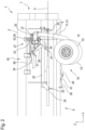
- Fig. 1 shows an attachment 1 according to the invention, in this case a harvesting attachment for a forage harvester.
- the attachment 1 has a frame 2, which is coupled to the forage harvester, not shown here, in a working mode with a coupling area 8, shown schematically here, which is arranged on a coupling side 5.
- the attachment 1 is supported in a self-supporting manner by the forage harvester.
- the figures are related to the coupled state of the attachment 1, the longitudinal axis X, the transverse axis Y and the vertical axis Z of the forage harvester.
- the frame 2 is significantly longer in the direction of the transverse axis Y than in the direction of the longitudinal axis X, so that the coupling side 5, as well as an opposite front side (not visible in the figures), can be referred to as the long side of the frame 2.
- a drawbar side 4 arranged to the side of the coupling side 5 can be referred to as the narrow side.
- Fig. 1 as well as the detailed view in Fig. 4 show the attachment 1 according to a transport mode in which it can be pulled by a tractor, also not shown, for example the forage harvester itself.
- the intended direction of travel runs (anti-)parallel to the transverse axis Y, so that a permissible width transverse to the direction of travel is not exceeded when driving on the road.
- the frame 2 is connected to a drawbar 50, via which it is coupled to the tractor.
- the drawbar 50 is adjustable between a transport position, which, for example, in Fig. 1 is shown and in which it protrudes from the drawbar side 4, and a working position in which it is pivoted towards the frame 2. The corresponding pivoting movement is not shown here.
- the attachment 1 also has a chassis 10 which, in the transport mode, is arranged in a transport position in which it is at least partially arranged vertically under the frame 2 in order to support the latter.
- a predominant part of the weight of the frame 2 rests on the chassis 10.
- the chassis 10 has two wheels 15, which are rotatably mounted on a suspension part 11, more precisely on an axle section 12 of the same. In the transport position, the frame 2 rests with an underside 6 on the axle section 12, so that it can be supported via the wheels 15 against a floor, not shown here.
- the suspension part 11 has a side section 13 which is rigidly connected thereto and which is located partly on the underside 6 and on the coupling side 5, which is also referred to below as the retraction side, laterally of the frame 2 upwards to a suspension bearing element or suspension -Pivot bearing 14 extends, via which the suspension part 11 is connected to a carriage element 20 of an adjusting mechanism 18.
- the suspension pivot bearing 14 enables a pivoting movement of the suspension part 11 and thus of the entire chassis 10 relative to the carriage element 20 about a pivot axis S.
- the carriage element 20 has a sleeve section 21 which engages from the outside on a guide rod 23 and is slidably guided thereon.
- the carriage element 20 - and the suspension part 11 connected to it - can be displaced relative to the frame 2 along a displacement axis V defined by the guide rod 23.
- the displacement axis V runs parallel to the transverse axis Y and therefore horizontally.
- the displacement axis V and the pivot axis S run at an angle to one another, for example at an angle of over 70°.
- the carriage element 20 also has a (in Fig. 4 recognizable) guide element 22, which engages with a guide track 28 and together with this forms a rotary guide 27.
- the guide track 28 does not run parallel to the displacement axis V, but rather in the manner of a helical line around it.
- a displacement of the carriage element 20 along the guide rod 23 causes a rotation about the displacement axis V.
- the course of the guide track 28 only deviates slightly from the displacement axis V, so that a displacement of the carriage element 20 along the guide rod 23 only results in a total rotation leads to an angle of 4°.
- a first actuator which in this case is designed as a (for example hydraulically acting) first cylinder 24, is connected on the one hand to the frame 2 via a first cylinder pivot bearing 25 and on the other hand to the slide element 20 via a second cylinder pivot bearing 26. It effects by changing the length, the displacement of the carriage element 20 along the displacement axis V and the rotation about the displacement axis V which is forcibly coupled thereto, which together correspond to a primary movement.
- the side part 13 of the suspension element 11 is connected to the carriage element 20 via the suspension pivot bearing 14.
- This secondary movement is driven by a second actuator, which is designed as a (for example hydraulically acting) second cylinder 30 and is connected to the slide element 20 via a third cylinder pivot bearing 31 and to a deflection lever 33 via a fourth cylinder pivot bearing 32.
- the latter is in turn connected to the slide element 20 via a deflection lever pivot bearing 34.
- the deflection lever 33 is connected via a first connecting link pivot bearing 36 (which in this case is coaxial to the fourth cylinder pivot bearing 32) to a connecting link 35, which in turn is connected to the side section 13 via a second connecting link pivot bearing 37 at a distance from the pivot axis S is.
- the pivot bearings 31, 32, 34, 36, 37 mentioned can each have one degree of freedom, but several degrees of freedom would also be conceivable.
- a locking element 41 is arranged on the underside 6 of the frame 2, by means of which the chassis 10 can be locked in the transport position.
- a securing pin 38 rigidly connected to the frame 2 engages in an opening in the axle section 12 that is not visible in the figures and also contributes to the mechanical connection between the frame 2 and the chassis 10.
- the locking element 41 can be released via a third actuator, which in the present case is designed as a third cylinder 40. If the attachment 1 is to be used for field cultivation, it is first coupled to the forage harvester so that the latter supports it in a self-supporting manner. The drawbar 50 can then be removed from the forage harvester from the in Fig. 1 The transport position shown can be adjusted to its working position.
- the adjustment of the third cylinder 40 is coupled to the adjustment of the drawbar 50, so that the locking element 41 is only released when the adjustment of the drawbar 50 from its transport position to its working position has at least begun.
- Adjusting the drawbar 50 could, for example, control a valve through which the third cylinder 40 is activated hydraulically.
- the drawbar 50 and the third cylinder 40 could also be controlled by a higher-level control that guarantees the time sequence shown.
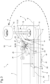
- the first cylinder 24 and the second cylinder 30 are also controlled from the forage harvester in order to adjust the chassis 10 to an in Fig. 3 and 5 to effect the working position shown. In the working position, the chassis 10 is arranged predominantly horizontally to the side of the frame 2 and vertically at least at the same height (sometimes even above it).
- the first cylinder 24 is first activated so that it extends and exerts a pressure force on the carriage element 20. As described above, this leads to the primary movement, i.e. a translational displacement along the displacement axis V and a parallel rotation about the displacement axis V, through which the chassis 10 is pivoted away from the frame 2 by an angle of 4 °.
- the primary movement leads the chassis 10 out of the in Fig. 1 transport position shown in an in Fig. 2 shown intermediate position, in which it is arranged much closer to a rear side 7 of the frame 2 arranged opposite the drawbar side 4.
- the chassis 10 is then moved into the in according to the secondary movement Fig. 3 and 5 shown working position pivoted.
- the second cylinder 30 contracts and exerts a tensile force on the deflection lever 33, which in turn leads to a tensile force on the connecting link 35 via a corresponding torque.
- the latter in turn leads to a torque on the suspension part 11 and thus to a pivoting movement about the pivot axis S, which in this example occurs at an angle of approximately 180 °.
- Fig.3 an approximate movement path B of an impeller 15 is shown when pivoting from the intermediate position into the working position. It is clearly visible that the impeller 15 (as well as other parts of the chassis 10) moves past the rear side 7 at the level of the frame 2. This is in turn made possible by the combination of primary movement and secondary movement, in which the primary movement into the intermediate position positions the chassis 10 appropriately and onto the Secondary movement prepared, in which a collision between the chassis 10 and the frame 2 is avoided in this way.
Landscapes
- Life Sciences & Earth Sciences (AREA)
- Zoology (AREA)
- Engineering & Computer Science (AREA)
- Mechanical Engineering (AREA)
- Soil Sciences (AREA)
- Environmental Sciences (AREA)
- Agricultural Machines (AREA)
Applications Claiming Priority (1)
| Application Number | Priority Date | Filing Date | Title |
|---|---|---|---|
| DE102022110404.4A DE102022110404A1 (de) | 2022-04-28 | 2022-04-28 | Anbaugerät zur feldbearbeitung |
Publications (1)
| Publication Number | Publication Date |
|---|---|
| EP4272527A1 true EP4272527A1 (fr) | 2023-11-08 |
Family
ID=86272136
Family Applications (1)
| Application Number | Title | Priority Date | Filing Date |
|---|---|---|---|
| EP23170442.0A Pending EP4272527A1 (fr) | 2022-04-28 | 2023-04-27 | Outil de montage pour l'usinage de champs |
Country Status (2)
| Country | Link |
|---|---|
| EP (1) | EP4272527A1 (fr) |
| DE (1) | DE102022110404A1 (fr) |
Families Citing this family (1)
| Publication number | Priority date | Publication date | Assignee | Title |
|---|---|---|---|---|
| US12082529B2 (en) * | 2018-11-16 | 2024-09-10 | Cnh Industrial America Llc | Wheel locking assembly for a harvester header |
Citations (6)
| Publication number | Priority date | Publication date | Assignee | Title |
|---|---|---|---|---|
| US20050144921A1 (en) * | 1999-05-28 | 2005-07-07 | Yeomans Sidney W. | Header for a harvester having an integral transport system |
| US7926249B1 (en) * | 2009-11-17 | 2011-04-19 | Cnh America Llc | Transport system for a harvest header |
| US20160066509A1 (en) * | 2014-09-08 | 2016-03-10 | Cnh Industrial America Llc | Windrow shield control system for a header of an agricultural harvester |
| EP2656715B1 (fr) | 2012-04-26 | 2017-08-02 | Macdon Industries Ltd | Système de transport de moissonneuse de type traction avec une roue de transport pouvant passer sous le système d'engagement de récolte |
| EP2939519B1 (fr) | 2014-05-02 | 2018-08-15 | CNH Industrial Belgium nv | Système de transport pour la tête de récolte d'une moissonneuse agricole |
| US20190200511A1 (en) * | 2018-01-02 | 2019-07-04 | CNH Industrial America, LLC | Lateral transport system for harvester and methods of using the same |
-
2022
- 2022-04-28 DE DE102022110404.4A patent/DE102022110404A1/de active Pending
-
2023
- 2023-04-27 EP EP23170442.0A patent/EP4272527A1/fr active Pending
Patent Citations (8)
| Publication number | Priority date | Publication date | Assignee | Title |
|---|---|---|---|---|
| US20050144921A1 (en) * | 1999-05-28 | 2005-07-07 | Yeomans Sidney W. | Header for a harvester having an integral transport system |
| US7926249B1 (en) * | 2009-11-17 | 2011-04-19 | Cnh America Llc | Transport system for a harvest header |
| EP2322024A1 (fr) | 2009-11-17 | 2011-05-18 | CNH Belgium N.V. | Système de transport et procédé pour moissonneuse |
| EP2656715B1 (fr) | 2012-04-26 | 2017-08-02 | Macdon Industries Ltd | Système de transport de moissonneuse de type traction avec une roue de transport pouvant passer sous le système d'engagement de récolte |
| EP2656716B1 (fr) * | 2012-04-26 | 2019-06-05 | Macdon Industries Ltd | Système de transport de moissonneuse de type traction où la machine demeure équilibrée sur des roues de transport et l'attelage que le système de transport est déployé |
| EP2939519B1 (fr) | 2014-05-02 | 2018-08-15 | CNH Industrial Belgium nv | Système de transport pour la tête de récolte d'une moissonneuse agricole |
| US20160066509A1 (en) * | 2014-09-08 | 2016-03-10 | Cnh Industrial America Llc | Windrow shield control system for a header of an agricultural harvester |
| US20190200511A1 (en) * | 2018-01-02 | 2019-07-04 | CNH Industrial America, LLC | Lateral transport system for harvester and methods of using the same |
Also Published As
| Publication number | Publication date |
|---|---|
| DE102022110404A1 (de) | 2023-11-02 |
Similar Documents
| Publication | Publication Date | Title |
|---|---|---|
| DE3442557C2 (de) | Anschluß- und Kupplungsvorrichtung zum frontseitigen Anbau an ein Arbeitsfahrzeug | |
| DE69017362T2 (de) | Landmaschine mit verbesserter Aufhängungsvorrichtung der Arbeitswerkzeugeeinheit. | |
| EP3122168B1 (fr) | Appareil de travail du sol comprenant un dispositif d'étrillage et d'aplanissement | |
| DE2948899A1 (de) | Fahrzeug mit geraete-schnellkuppler | |
| DE6603209U (de) | Pflug insbesondere anhaenge- oder aufsattelbeetpflug | |
| EP3166379B1 (fr) | Charrue pivotante avec roue de profondeur orientable destinée à être montée sur le bâti de la charrue | |
| DE19951080A1 (de) | Selbstfahrendes landwirtschaftliches Fahrzeug | |
| EP4272527A1 (fr) | Outil de montage pour l'usinage de champs | |
| AT511565A2 (de) | Automatische Erstkörper-Schnittbreiteneinstellung | |
| DE3322551C2 (de) | Zwischenstück zum Ausschalten der Seitenbeweglichkeit von Unterlenkern eines Ackerschleppers | |
| EP4101275B1 (fr) | Appareil accessoire destiné au traitement du sol | |
| DE68921495T2 (de) | Landwirtschaftsrolle. | |
| EP4074156A1 (fr) | Dispositif timon pour une machine agricole tractée | |
| DE29818457U1 (de) | Landwirtschaftliche Bearbeitungsmaschine | |
| EP0350513B1 (fr) | Appareil pour travailler le sol | |
| EP3598882B1 (fr) | Accessoire agricole | |
| EP4101276B1 (fr) | Appareil accessoire destiné au traitement du sol | |
| DE3926381C1 (en) | Agricultural machine drive system - incorporates clutch with operating element connected to swivelling outer frame parts | |
| DE29600075U1 (de) | Pflug | |
| DE10120845B4 (de) | Hydromechanische Steuerungsvorrichtung für eine mehrteilige landwirtschaftliche Arbeitsmaschine | |
| EP1859665B1 (fr) | Machine agricole tractée à grande largeur de travail | |
| EP4278875A2 (fr) | Outil pour la culture des champs | |
| EP4169370A1 (fr) | Appareil additionnel pour une machine agricole | |
| EP3106010B1 (fr) | Dispositif de semis | |
| WO2023006659A1 (fr) | Ensemble semi-remorque |
Legal Events
| Date | Code | Title | Description |
|---|---|---|---|
| PUAI | Public reference made under article 153(3) epc to a published international application that has entered the european phase |
Free format text: ORIGINAL CODE: 0009012 |
|
| STAA | Information on the status of an ep patent application or granted ep patent |
Free format text: STATUS: THE APPLICATION HAS BEEN PUBLISHED |
|
| AK | Designated contracting states |
Kind code of ref document: A1 Designated state(s): AL AT BE BG CH CY CZ DE DK EE ES FI FR GB GR HR HU IE IS IT LI LT LU LV MC ME MK MT NL NO PL PT RO RS SE SI SK SM TR |
|
| STAA | Information on the status of an ep patent application or granted ep patent |
Free format text: STATUS: REQUEST FOR EXAMINATION WAS MADE |
|
| 17P | Request for examination filed |
Effective date: 20240327 |
|
| RBV | Designated contracting states (corrected) |
Designated state(s): AL AT BE BG CH CY CZ DE DK EE ES FI FR GB GR HR HU IE IS IT LI LT LU LV MC ME MK MT NL NO PL PT RO RS SE SI SK SM TR |