EP4272286B1 - An electrical safety contact with removable contact bridge - Google Patents
An electrical safety contact with removable contact bridge Download PDFInfo
- Publication number
- EP4272286B1 EP4272286B1 EP21851631.8A EP21851631A EP4272286B1 EP 4272286 B1 EP4272286 B1 EP 4272286B1 EP 21851631 A EP21851631 A EP 21851631A EP 4272286 B1 EP4272286 B1 EP 4272286B1
- Authority
- EP
- European Patent Office
- Prior art keywords
- receiving body
- openings
- contact
- electrical safety
- drain opening
- Prior art date
- Legal status (The legal status is an assumption and is not a legal conclusion. Google has not performed a legal analysis and makes no representation as to the accuracy of the status listed.)
- Active
Links
Images


Classifications
-
- B—PERFORMING OPERATIONS; TRANSPORTING
- B66—HOISTING; LIFTING; HAULING
- B66B—ELEVATORS; ESCALATORS OR MOVING WALKWAYS
- B66B13/00—Doors, gates, or other apparatus controlling access to, or exit from, cages or lift well landings
- B66B13/22—Operation of door or gate contacts
-
- H—ELECTRICITY
- H01—ELECTRIC ELEMENTS
- H01R—ELECTRICALLY-CONDUCTIVE CONNECTIONS; STRUCTURAL ASSOCIATIONS OF A PLURALITY OF MUTUALLY-INSULATED ELECTRICAL CONNECTING ELEMENTS; COUPLING DEVICES; CURRENT COLLECTORS
- H01R13/00—Details of coupling devices of the kinds covered by groups H01R12/70 or H01R24/00 - H01R33/00
- H01R13/46—Bases; Cases
- H01R13/52—Dustproof, splashproof, drip-proof, waterproof, or flameproof cases
- H01R13/5227—Dustproof, splashproof, drip-proof, waterproof, or flameproof cases with evacuation of penetrating liquids
-
- H—ELECTRICITY
- H01—ELECTRIC ELEMENTS
- H01R—ELECTRICALLY-CONDUCTIVE CONNECTIONS; STRUCTURAL ASSOCIATIONS OF A PLURALITY OF MUTUALLY-INSULATED ELECTRICAL CONNECTING ELEMENTS; COUPLING DEVICES; CURRENT COLLECTORS
- H01R31/00—Coupling parts supported only by co-operation with counterpart
- H01R31/08—Short-circuiting members for bridging contacts in a counterpart
Definitions
- the present invention relates to an electrical safety contact with a removable contact bridge as defined in the preamble of claim 1 as used, for example, in an elevator installation structure.
- safety contacts with a removable bridge are widely used to enable/disable certain features, e.g. to deny electric consent to start the elevator until all landing doors and cabin doors are properly closed.
- Italian patent application ITMI20110042 discloses a safety electric contact with removable contact bridge according to the pre-characterizing portion of claim 1.
- the body of the electrical contact has special openings, against which contact elements are located, such terminals of the removable body being intended to fit into the electrical contact through such openings to establish electrical communication between the contact elements.
- openings should not be too large. Nevertheless, said openings identify passages through which liquids or dirt can enter the body of the electrical contact.
- electrical safety contacts which are positioned to have such electrical terminal receiving openings facing upwards. This occurs because the material that infiltrates the body of electrical safety contacts tends to build up and settle on the portions that define the contact elements proper of the electrical safety contacts, and the same applies to any liquids inside the body of the electrical safety contacts.
- this invention is based on the technical problem of designing and providing an electrical safety contact with a removable contact bridge, that has such structural and functional characteristics as to fulfill the above needs, while obviating the teachings as mentioned above with reference to prior art electrical safety contacts.
- numeral 1 generally designates an electrical safety contact with a removable bridge 2 according to the invention.
- the removable contact bridge 2 comprises rod-like contacts 3 which are in electrical communication with each other and project parallel to each other from the same side of a head 2a of the removable bridge 2.
- the electrical safety contact 1 comprises a receiving hollow body 4 intended to be secured to an external support by means of fastening means.
- the receiving body 4 identifies an internal cavity 14 and has the shape of a parallelepiped defined by:
- the receiving body 4 is a body having the shape of a rectangular or square parallelepiped.
- the receiving body 4 comprises a first side wall 10 with two passing-through openings 5, extending along a predetermined axis Z-Z, formed therein.
- passing-through openings 5 are located substantially at the contact elements 6 and allow insertion/disconnection of the rod-like contacts 3 of the contact bridge 2 into/from the receiving body 4 along a predetermined insertion path (see broken line S of Figure 2 ).
- contact elements 6 it should be noted that these contact elements are supported in a well-known manner in the receiving body 4 so that, upon insertion of the aforementioned rod-like contacts 3 of the contact bridge 2 through the passing-through openings 5, these contact elements 6 are reversibly retracted into the receiving body 4, against the elastic return action exerted by the respective contact springs 7 which support them, to move from a forward position (see Figures 2 and 4 ), in which said contact elements 6 are substantially at their respective through openings 5, to a more retracted position inside the receiving body 6 (see Figure 1 ).
- each of the two aforementioned contact springs 7 is a thin leaf spring having a reduced thickness, approximately ranging from 0.10 to 0.20 mm, having a width approximately ranging from 5 to 10 mm, preferably of 7 mm.
- the receiving body 4 is a closed body and preferably comprises, in addition to the aforementioned passing-through openings 5 for insertion and disconnection of the rod-like contacts 3 of the contact bridge 2 into/from the receiving body 4, two additional passing-through openings 8 to allow electric conductors to be introduced into the receiving body 4 to their respective wiring terminals 11.
- Each wiring terminal is connected in electrical continuity with a respective contact element 6.
- the aforementioned springs 7 are made of an electrically conductive material, so that electrical continuity between each contact element 6 and its respective wiring terminal 11 will be provided by the contact leaf spring 7.
- the aforementioned receiving body 4 comprises at least one drain opening 13 to allow liquids and/or dirt to pass and exit from the cavity 14 of said receiving body 4, whereby a drain channel extending from the aforementioned first passing-through openings 5 to the aforementioned at least one drain opening 13 is identified in said receiving body.
- the aforementioned at least one drain opening 13 is positioned at a wall 15 that identifies one side of the receiving body 4 opposite to the side identified by the aforementioned first wall 10 having first passing-through openings (5).
- the aforementioned at least one drain opening 13 is positioned at a wall 15 of said receiving body 4 that identifies a side of said receiving body 4 parallel to the side identified by said one first wall 10 having first passing-through openings 5.
- the aforementioned at least one drain opening 13 identifies a passage which, when said electrical safety contact is in use, has a minimum free cross-section of at least 4 mm 2 , more preferably a minimum free cross-section of at least 6 mm 2 , to ensure drainage of any liquids and escape of any dirt.
- the aforementioned first passing-through openings 5 and the aforementioned at least one drain opening 13 are formed at with distinct side walls 10,15 of said receiving hollow body 4.
- said at least one drain opening 13 identifies a passage:
- said at least one drain opening 13 comprises two distinct drain openings 13.
- the receiving body 4 comprises a dividing partition 16 to divide the internal cavity 14 into two separate chambers, a respective spring 7 and a respective contact element 6 being accommodated inside each of said chambers.
- each of said two separate chambers is formed with at least one respective drain opening 13.
- the electrical safety contact with a removable contact bridge of the present invention fulfills the above mentioned need and also obviates the prior art drawbacks as set out in the introduction of this disclosure.
- the characteristic of providing said at least one drain opening can ensure the escape of any liquids or dirt in the internal compartment of the receiving body from the electrical safety contact through the first passing-through openings formed to allow insertion of the rod-like contacts 3 of the contact bridge.
- this is particularly useful when the electrical safety contact is positioned, for example, in the elevator structure, so that the aforementioned first passing-through openings, provided to allow insertion of the rod-like contacts of the contact bridge, will face upwards.
- any dirt or liquids will apparently tend to enter by gravity the internal compartment of the receiving body and, still by gravity, will travel along the aforementioned drain channel which extends from such first passing-through openings to the aforementioned at least one drain opening, thereby exiting the internal cavity of the receiving body.
- the openings formed for insertion of the electric conductors would not be useful for this purpose since, in operation, the presence of the electric wiring terminals and the electric conductors wired to these terminals would reduce the passage section thereby preventing or hindering the escape of dirt or liquids.
- the aforementioned drain channel identified in the receiving body between the first passing-through openings and the aforementioned at least one drain opening is distinct and does not extend through said wiring terminals to prevent oxidation phenomena of the conductive parts of said wiring terminals during operation.
- a further advantage of the electrical safety contact with a removable bridge of the present invention is its unique structural simplicity.
Landscapes
- Connector Housings Or Holding Contact Members (AREA)
- Details Of Connecting Devices For Male And Female Coupling (AREA)
- Investigating Or Analyzing Materials By The Use Of Electric Means (AREA)
- Food-Manufacturing Devices (AREA)
- Instruments For Viewing The Inside Of Hollow Bodies (AREA)
- Dry Shavers And Clippers (AREA)
Description
- The present invention relates to an electrical safety contact with a removable contact bridge as defined in the preamble of claim 1 as used, for example, in an elevator installation structure.
- In elevator installations safety contacts with a removable bridge are widely used to enable/disable certain features, e.g. to deny electric consent to start the elevator until all landing doors and cabin doors are properly closed.
- The requirements to be met by safety contacts are generally set forth by stringent standards. For instance, the terminals of the removable contact bridge must fit into the receiving part of the contact, to only electrically close the electric circuit when the mechanical closing members have been engaged for a minimum working stroke, generally at least 7 mm.
- Italian patent application
ITMI20110042 - Concerning the terminals of the removable contact bridge, it should be noted that their size will generally meet strict dimension requirements that have currently become a standard, namely in terms of sizes.
- The body of the electrical contact has special openings, against which contact elements are located, such terminals of the removable body being intended to fit into the electrical contact through such openings to establish electrical communication between the contact elements.
- It should be noted that, to prevent a user of an elevator installation from willingly or unwillingly introducing a finger into the body of the electrical contact, and from reaching a contact element, such openings should not be too large. Nevertheless, said openings identify passages through which liquids or dirt can enter the body of the electrical contact.
- Generally, while the infiltration of liquids or dirt is an undesired aspect, it does not entail major problems and does not affect proper operation of the electrical safety contact, unless the liquid or dirt builds up over time inside the body of the electrical safety contact.
- Furthermore, a greater incidence of operating defects has been found in electrical safety contacts, which are positioned to have such electrical terminal receiving openings facing upwards. This occurs because the material that infiltrates the body of electrical safety contacts tends to build up and settle on the portions that define the contact elements proper of the electrical safety contacts, and the same applies to any liquids inside the body of the electrical safety contacts.
- In view of these problems, the need is apparently felt for an electrical safety contact that can avoid build-up of liquids and/or dirt in the body of the electrical safety contact.
- Therefore, this invention is based on the technical problem of designing and providing an electrical safety contact with a removable contact bridge, that has such structural and functional characteristics as to fulfill the above needs, while obviating the teachings as mentioned above with reference to prior art electrical safety contacts.
- This problem is solved by an electrical safety contact with a removable contact bridge as defined by the features of claim 1.
- Further features and advantages of the electrical safety contact with a removable contact bridge of the invention will be apparent upon reading of the following description of a few preferred exemplary embodiments thereof, which is given by way of illustration and without limitation with reference to the accompanying figures, in which:
-
Figure 1 is a plan view of an electrical safety contact of the invention with a contact bridge inserted therein and with certain internal parts outlined by dashed lines; -
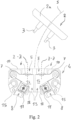
Figure 2 shows a plan view of the electric contact ofFigure 1 with the contact bridge pulled out and with the cover of the body of the electric contact removed; -
Figure 3 shows a perspective view from the rear side of the electric contact ofFigure 1 and of the corresponding removable contact bridge in the pulled-out configuration and -
Figure 4 shows a perspective view of the body of the electrical safety contact ofFigure 1 with the cover removed, to expose its internal structure. - Referring to the accompanying figures, numeral 1 generally designates an electrical safety contact with a
removable bridge 2 according to the invention. - The
removable contact bridge 2 comprises rod-like contacts 3 which are in electrical communication with each other and project parallel to each other from the same side of a head 2a of theremovable bridge 2. - The electrical safety contact 1 comprises a receiving hollow body 4 intended to be secured to an external support by means of fastening means.
- The receiving body 4 identifies an
internal cavity 14 and has the shape of a parallelepiped defined by: - a
rear bottom wall 9, - side walls projecting out of said bottom wall and
- a
front wall 12 secured to the side walls and acting as a closing cover of the receiving hollow body 4. - According to the illustrated embodiment, the receiving body 4 is a body having the shape of a rectangular or square parallelepiped.
-
Contact elements 6 supported by respectivecontact leaf springs 7 are received inside the receiving body 4 in protected positions. - The receiving body 4 comprises a
first side wall 10 with two passing-through openings 5, extending along a predetermined axis Z-Z, formed therein. - These passing-through openings 5 are located substantially at the
contact elements 6 and allow insertion/disconnection of the rod-like contacts 3 of thecontact bridge 2 into/from the receiving body 4 along a predetermined insertion path (see broken line S ofFigure 2 ). - In the illustrated embodiment, when the electrical terminals of the
contact bridge 2 are inserted into the receiving hollow body 4 to the bottom through the passing-through openings 5 (seeFigure 1 ), such rod-like contacts 3 extend substantially parallel to the aforementioned axis Z-Z of the passing-through openings 5. - Referring to the
contact elements 6, it should be noted that these contact elements are supported in a well-known manner in the receiving body 4 so that, upon insertion of the aforementioned rod-like contacts 3 of thecontact bridge 2 through the passing-through openings 5, thesecontact elements 6 are reversibly retracted into the receiving body 4, against the elastic return action exerted by therespective contact springs 7 which support them, to move from a forward position (seeFigures 2 and4 ), in which saidcontact elements 6 are substantially at their respective through openings 5, to a more retracted position inside the receiving body 6 (seeFigure 1 ). - Preferably, each of the two
aforementioned contact springs 7 is a thin leaf spring having a reduced thickness, approximately ranging from 0.10 to 0.20 mm, having a width approximately ranging from 5 to 10 mm, preferably of 7 mm. - The receiving body 4 is a closed body and preferably comprises, in addition to the aforementioned passing-through openings 5 for insertion and disconnection of the rod-
like contacts 3 of thecontact bridge 2 into/from the receiving body 4, two additional passing-throughopenings 8 to allow electric conductors to be introduced into the receiving body 4 to theirrespective wiring terminals 11. - Each wiring terminal is connected in electrical continuity with a
respective contact element 6. - Preferably, the
aforementioned springs 7 are made of an electrically conductive material, so that electrical continuity between eachcontact element 6 and itsrespective wiring terminal 11 will be provided by thecontact leaf spring 7. - Advantageously, the aforementioned receiving body 4 comprises at least one drain opening 13 to allow liquids and/or dirt to pass and exit from the
cavity 14 of said receiving body 4, whereby a drain channel extending from the aforementioned first passing-through openings 5 to the aforementioned at least one drain opening 13 is identified in said receiving body. - Preferably, the aforementioned at least one
drain opening 13 is positioned at awall 15 that identifies one side of the receiving body 4 opposite to the side identified by the aforementionedfirst wall 10 having first passing-through openings (5). - Preferably, the aforementioned at least one drain opening 13 is positioned at a
wall 15 of said receiving body 4 that identifies a side of said receiving body 4 parallel to the side identified by said onefirst wall 10 having first passing-through openings 5. - According to the present invention, the aforementioned at least one drain opening 13 identifies a passage which, when said electrical safety contact is in use, has a minimum free cross-section of at least 4 mm2, more preferably a minimum free cross-section of at least 6 mm2, to ensure drainage of any liquids and escape of any dirt.
- Preferably, the aforementioned first passing-through openings 5 and the aforementioned at least one drain opening 13 are formed at with
distinct side walls - It should be noted that said at least one drain opening 13 identifies a passage:
- extending to an axial section inside said receiving body 4 and
- delimited by
internal side walls 18 over the entire length of said passage extending inside said receiving body 4. - According to the preferred embodiment as shown in the figures, said at least one drain opening 13 comprises two
distinct drain openings 13. - Preferably, the receiving body 4 comprises a dividing
partition 16 to divide theinternal cavity 14 into two separate chambers, arespective spring 7 and arespective contact element 6 being accommodated inside each of said chambers. In this configuration, each of said two separate chambers is formed with at least one respective drain opening 13. - It will be appreciated from the foregoing, the electrical safety contact with a removable contact bridge of the present invention fulfills the above mentioned need and also obviates the prior art drawbacks as set out in the introduction of this disclosure.
- Thus, the characteristic of providing said at least one drain opening can ensure the escape of any liquids or dirt in the internal compartment of the receiving body from the electrical safety contact through the first passing-through openings formed to allow insertion of the rod-
like contacts 3 of the contact bridge. - Advantageously, this is particularly useful when the electrical safety contact is positioned, for example, in the elevator structure, so that the aforementioned first passing-through openings, provided to allow insertion of the rod-like contacts of the contact bridge, will face upwards. Here, any dirt or liquids will apparently tend to enter by gravity the internal compartment of the receiving body and, still by gravity, will travel along the aforementioned drain channel which extends from such first passing-through openings to the aforementioned at least one drain opening, thereby exiting the internal cavity of the receiving body.
- In this regard, it should be noted that the openings formed for insertion of the electric conductors would not be useful for this purpose since, in operation, the presence of the electric wiring terminals and the electric conductors wired to these terminals would reduce the passage section thereby preventing or hindering the escape of dirt or liquids.
- Further, according to a preferred embodiment, the aforementioned drain channel identified in the receiving body between the first passing-through openings and the aforementioned at least one drain opening is distinct and does not extend through said wiring terminals to prevent oxidation phenomena of the conductive parts of said wiring terminals during operation.
- A further advantage of the electrical safety contact with a removable bridge of the present invention is its unique structural simplicity.
- Those skilled in the art will obviously appreciate that a number of changes and variants may be made to the above described electrical safety contact with a contact bridge, still within the scope of the invention, as defined in the following claims.
Claims (12)
- An electrical safety contact with removable contact bridge, comprising a receiving body (4) that identifies an internal cavity (14) inside which contact elements (6) are housed in a protected position, supported by respective springs (7) and in electrical continuity with respective wiring terminals (11) for electrical conductors, wherein:- said receiving body (4) comprises a first wall (10) provided with first passing-through openings (5) of predetermined axis (Z-Z) positioned in correspondence with said contact elements (6) to allow the insertion or disconnection of rod-shaped contacts (3) of a contact bridge (2) in said axial direction (Z-Z) of said first passing-through openings (5),characterized in that said receiving body (4) comprises at least one drain opening (13) to allow liquids and/or dirt to pass and exit from said internal cavity (14) of said receiving body (4), in said receiving body being identified a drain channel extended from said first passing-through openings (5) to said at least one drain opening (13), wherein said at least one drain opening (13) identifies a passage that, when said electric safety contact is used, has a minimum free cross section of at least 4 mm2 to ensure the drainage of any liquids and the escape of any dirt.
- Electrical safety contact according to claim 1, wherein said at least one drain opening (13) is positioned in correspondence with a wall (15) that identifies one side of said receiving body (4) opposite to the side identified by said one first wall (10) provided with first passing-through openings (5).
- Electrical safety contact according to claim 1 or 2, wherein said at least one drain opening (13) is positioned in correspondence with a wall (15) that identifies a side of said receiving body (4) parallel to the side identified by said first wall (10) provided with first passing-through openings (5).
- Electrical safety contact according to any one of claims 1 to 3, wherein said at least one drain opening (13) identifies a passage that, when said electric safety contact is used, has a minimum free cross section of at least 6 mm2 to ensure the drainage of any liquids and the escape of any dirt.
- Electrical safety contact according to any one of claims 1 to 4, wherein:- said receiving hollow body (4) comprises a rear bottom wall (9), side walls projecting from said bottom wall and a front wall (12) secured to the side walls with the function of closing cover of the receiving hollow body (4) and- said first passing-through openings (5) and said at least one drain opening (13) are formed in correspondence with distinct side walls (10,15) of said receiving hollow body (4).
- Electrical safety contact according to any one of claims 1 to 5, wherein said at least one drain opening (13) identifies a passage that is:- extended for an axial section inside said receiving body (4) and- delimited by internal side walls (18) for the entire length of said extended passage p inside said receiving body (4).
- Electrical safety contact according to any one of claims 1 to 6, wherein said at least one drain opening (13) comprises two distinct drain openings (13).
- Electrical safety contact according to any one of claims 1 to 7, wherein:- said receiving body (4) comprises a dividing partition (16) to divide said cavity (14) into two separate chambers, a respective spring (7) and a respective contact element (6) being housed inside each of said chambers and- each of said two separate chambers is provided with at least one respective drain opening (13).
- Electric safety contact according to any one of claims 1 to 8, wherein said receiving body (4) comprises second passing-through openings (8) suitable for allowing the insertion in said receiving body (4) of electrical conductors until reaching said wiring terminals (11).
- Electrical safety contact according to any one of claims 1 to 9, wherein:- said springs (7) are made of electrically conductive material and- the electrical continuity between a contact element (6) and a respective wiring terminal (11) is ensured by a respective of said springs (7).
- Electrical safety contact in accordance with any one of claims 1 to 10, comprising a removable bridge (3) having rod-shaped contacts (3) in electrical communication with each other and projecting parallel to each other from the same side of a head (2a) of the removable bridge (2), said rod-shaped contacts (3) being removably inserted/insertable in said receiving body (4) through said first openings (5) to establish an electrical continuity between said contact elements (6).
- Electrical safety contact according to any one of claims 1 to 11, wherein said drain channel identified in said receiving body (4) from said first passing-through openings (5) to said at least one drain opening (13) is distinct and not passing through said wiring terminals (11) to prevent in use oxidation phenomena of the conductive parts of said wiring terminals (11) from occurring.
Applications Claiming Priority (2)
| Application Number | Priority Date | Filing Date | Title |
|---|---|---|---|
| IT102020000032960A IT202000032960A1 (en) | 2020-12-31 | 2020-12-31 | ELECTRIC SAFETY CONTACT WITH REMOVABLE CONTACT BRIDGE |
| PCT/IB2021/062459 WO2022144820A1 (en) | 2020-12-31 | 2021-12-30 | An electrical safety contact with removable contact bridge |
Publications (3)
| Publication Number | Publication Date |
|---|---|
| EP4272286A1 EP4272286A1 (en) | 2023-11-08 |
| EP4272286C0 EP4272286C0 (en) | 2025-03-05 |
| EP4272286B1 true EP4272286B1 (en) | 2025-03-05 |
Family
ID=75252658
Family Applications (1)
| Application Number | Title | Priority Date | Filing Date |
|---|---|---|---|
| EP21851631.8A Active EP4272286B1 (en) | 2020-12-31 | 2021-12-30 | An electrical safety contact with removable contact bridge |
Country Status (4)
| Country | Link |
|---|---|
| EP (1) | EP4272286B1 (en) |
| CN (1) | CN116670060A (en) |
| IT (1) | IT202000032960A1 (en) |
| WO (1) | WO2022144820A1 (en) |
Families Citing this family (1)
| Publication number | Priority date | Publication date | Assignee | Title |
|---|---|---|---|---|
| WO2025082825A1 (en) * | 2023-10-20 | 2025-04-24 | Inventio Ag | Bridging device for creating a short-circuit |
Family Cites Families (3)
| Publication number | Priority date | Publication date | Assignee | Title |
|---|---|---|---|---|
| US4722700A (en) * | 1987-01-23 | 1988-02-02 | Amp Incorporated | Low insertion force terminal for use with circuit panel |
| IT1403308B1 (en) * | 2011-01-18 | 2013-10-17 | Astra Srl | ELECTRIC CONTACT |
| CA3082618A1 (en) * | 2019-06-08 | 2020-12-08 | Norman R. Byrne | Electrical receptacle with drain-through feature |
-
2020
- 2020-12-31 IT IT102020000032960A patent/IT202000032960A1/en unknown
-
2021
- 2021-12-30 CN CN202180087727.6A patent/CN116670060A/en active Pending
- 2021-12-30 EP EP21851631.8A patent/EP4272286B1/en active Active
- 2021-12-30 WO PCT/IB2021/062459 patent/WO2022144820A1/en not_active Ceased
Also Published As
| Publication number | Publication date |
|---|---|
| WO2022144820A1 (en) | 2022-07-07 |
| IT202000032960A1 (en) | 2022-07-01 |
| CN116670060A (en) | 2023-08-29 |
| EP4272286A1 (en) | 2023-11-08 |
| EP4272286C0 (en) | 2025-03-05 |
Similar Documents
| Publication | Publication Date | Title |
|---|---|---|
| EP2987175B1 (en) | Electric switch assembly | |
| CN110581469B (en) | Locking structure, electrical connection box and wire harness | |
| US10566741B2 (en) | Shielded connector | |
| US3942143A (en) | Electromagnetic switching apparatus, particularly motor contactor, with auxiliary contacts | |
| JP7083701B2 (en) | Lock structure, electrical junction box and wire harness | |
| CZ285268B6 (en) | Breaking system for a switch | |
| CN111201678B (en) | Connector | |
| KR880005640A (en) | Interchangeable electronic switchgear | |
| WO2022144820A1 (en) | An electrical safety contact with removable contact bridge | |
| US6784393B2 (en) | Arc quenching device for low-voltage switching devices | |
| EP2871657B1 (en) | Molded case circuit breaker | |
| US2072729A (en) | Safety switch | |
| CA2320782A1 (en) | Rack system for insertion of electrical printed circuit board assemblies | |
| JP4263851B2 (en) | Modular system for printed circuit boards with front element centering contact parts and independent receiving contact parts, in particular contact pieces, in the rack assembly | |
| US5984730A (en) | Waterproof electric plug with fuse holder | |
| KR101719138B1 (en) | Joint Connector with Compact Conducting Structure | |
| GB1568660A (en) | Electric current distributor | |
| CN108962641A (en) | Current switch element and the electric switch equipment including it can be removed | |
| KR100662677B1 (en) | Electrical connector with internal shield | |
| CN111049080A (en) | Electrical junction box | |
| KR20000016737A (en) | Sub-rack for plug-in printed circuit modules with means of damped discharge of electrostatic potential | |
| JP6275624B2 (en) | Electrical junction box | |
| KR20120070723A (en) | Solid state relay | |
| US20230016517A1 (en) | Auxiliary contact unit | |
| EP1178572B1 (en) | Connecting terminal fo printed board |
Legal Events
| Date | Code | Title | Description |
|---|---|---|---|
| STAA | Information on the status of an ep patent application or granted ep patent |
Free format text: STATUS: UNKNOWN |
|
| STAA | Information on the status of an ep patent application or granted ep patent |
Free format text: STATUS: THE INTERNATIONAL PUBLICATION HAS BEEN MADE |
|
| PUAI | Public reference made under article 153(3) epc to a published international application that has entered the european phase |
Free format text: ORIGINAL CODE: 0009012 |
|
| STAA | Information on the status of an ep patent application or granted ep patent |
Free format text: STATUS: REQUEST FOR EXAMINATION WAS MADE |
|
| 17P | Request for examination filed |
Effective date: 20230727 |
|
| AK | Designated contracting states |
Kind code of ref document: A1 Designated state(s): AL AT BE BG CH CY CZ DE DK EE ES FI FR GB GR HR HU IE IS IT LI LT LU LV MC MK MT NL NO PL PT RO RS SE SI SK SM TR |
|
| DAV | Request for validation of the european patent (deleted) | ||
| DAX | Request for extension of the european patent (deleted) | ||
| GRAP | Despatch of communication of intention to grant a patent |
Free format text: ORIGINAL CODE: EPIDOSNIGR1 |
|
| STAA | Information on the status of an ep patent application or granted ep patent |
Free format text: STATUS: GRANT OF PATENT IS INTENDED |
|
| INTG | Intention to grant announced |
Effective date: 20241219 |
|
| GRAS | Grant fee paid |
Free format text: ORIGINAL CODE: EPIDOSNIGR3 |
|
| GRAA | (expected) grant |
Free format text: ORIGINAL CODE: 0009210 |
|
| STAA | Information on the status of an ep patent application or granted ep patent |
Free format text: STATUS: THE PATENT HAS BEEN GRANTED |
|
| AK | Designated contracting states |
Kind code of ref document: B1 Designated state(s): AL AT BE BG CH CY CZ DE DK EE ES FI FR GB GR HR HU IE IS IT LI LT LU LV MC MK MT NL NO PL PT RO RS SE SI SK SM TR |
|
| REG | Reference to a national code |
Ref country code: GB Ref legal event code: FG4D |
|
| REG | Reference to a national code |
Ref country code: CH Ref legal event code: EP |
|
| REG | Reference to a national code |
Ref country code: DE Ref legal event code: R096 Ref document number: 602021027302 Country of ref document: DE |
|
| REG | Reference to a national code |
Ref country code: IE Ref legal event code: FG4D |
|
| U01 | Request for unitary effect filed |
Effective date: 20250401 |
|
| U07 | Unitary effect registered |
Designated state(s): AT BE BG DE DK EE FI FR IT LT LU LV MT NL PT RO SE SI Effective date: 20250407 |
|
| PG25 | Lapsed in a contracting state [announced via postgrant information from national office to epo] |
Ref country code: RS Free format text: LAPSE BECAUSE OF FAILURE TO SUBMIT A TRANSLATION OF THE DESCRIPTION OR TO PAY THE FEE WITHIN THE PRESCRIBED TIME-LIMIT Effective date: 20250605 |
|
| PG25 | Lapsed in a contracting state [announced via postgrant information from national office to epo] |
Ref country code: ES Free format text: LAPSE BECAUSE OF FAILURE TO SUBMIT A TRANSLATION OF THE DESCRIPTION OR TO PAY THE FEE WITHIN THE PRESCRIBED TIME-LIMIT Effective date: 20250305 |
|
| PG25 | Lapsed in a contracting state [announced via postgrant information from national office to epo] |
Ref country code: NO Free format text: LAPSE BECAUSE OF FAILURE TO SUBMIT A TRANSLATION OF THE DESCRIPTION OR TO PAY THE FEE WITHIN THE PRESCRIBED TIME-LIMIT Effective date: 20250605 |
|
| PG25 | Lapsed in a contracting state [announced via postgrant information from national office to epo] |
Ref country code: HR Free format text: LAPSE BECAUSE OF FAILURE TO SUBMIT A TRANSLATION OF THE DESCRIPTION OR TO PAY THE FEE WITHIN THE PRESCRIBED TIME-LIMIT Effective date: 20250305 |
|
| PG25 | Lapsed in a contracting state [announced via postgrant information from national office to epo] |
Ref country code: GR Free format text: LAPSE BECAUSE OF FAILURE TO SUBMIT A TRANSLATION OF THE DESCRIPTION OR TO PAY THE FEE WITHIN THE PRESCRIBED TIME-LIMIT Effective date: 20250606 |
|
| PG25 | Lapsed in a contracting state [announced via postgrant information from national office to epo] |
Ref country code: SM Free format text: LAPSE BECAUSE OF FAILURE TO SUBMIT A TRANSLATION OF THE DESCRIPTION OR TO PAY THE FEE WITHIN THE PRESCRIBED TIME-LIMIT Effective date: 20250305 |
|
| PG25 | Lapsed in a contracting state [announced via postgrant information from national office to epo] |
Ref country code: PL Free format text: LAPSE BECAUSE OF FAILURE TO SUBMIT A TRANSLATION OF THE DESCRIPTION OR TO PAY THE FEE WITHIN THE PRESCRIBED TIME-LIMIT Effective date: 20250305 |
|
| PG25 | Lapsed in a contracting state [announced via postgrant information from national office to epo] |
Ref country code: CZ Free format text: LAPSE BECAUSE OF FAILURE TO SUBMIT A TRANSLATION OF THE DESCRIPTION OR TO PAY THE FEE WITHIN THE PRESCRIBED TIME-LIMIT Effective date: 20250305 |
|
| PG25 | Lapsed in a contracting state [announced via postgrant information from national office to epo] |
Ref country code: SK Free format text: LAPSE BECAUSE OF FAILURE TO SUBMIT A TRANSLATION OF THE DESCRIPTION OR TO PAY THE FEE WITHIN THE PRESCRIBED TIME-LIMIT Effective date: 20250305 |
|
| PG25 | Lapsed in a contracting state [announced via postgrant information from national office to epo] |
Ref country code: IS Free format text: LAPSE BECAUSE OF FAILURE TO SUBMIT A TRANSLATION OF THE DESCRIPTION OR TO PAY THE FEE WITHIN THE PRESCRIBED TIME-LIMIT Effective date: 20250705 |
|
| PLBE | No opposition filed within time limit |
Free format text: ORIGINAL CODE: 0009261 |
|
| STAA | Information on the status of an ep patent application or granted ep patent |
Free format text: STATUS: NO OPPOSITION FILED WITHIN TIME LIMIT |
|
| REG | Reference to a national code |
Ref country code: CH Ref legal event code: L10 Free format text: ST27 STATUS EVENT CODE: U-0-0-L10-L00 (AS PROVIDED BY THE NATIONAL OFFICE) Effective date: 20260114 |
|
| U20 | Renewal fee for the european patent with unitary effect paid |
Year of fee payment: 5 Effective date: 20251223 |
|
| 26N | No opposition filed |
Effective date: 20251208 |