EP4272286B1 - Elektrischer sicherheitskontakt mit abnehmbarer kontaktbrücke - Google Patents
Elektrischer sicherheitskontakt mit abnehmbarer kontaktbrücke Download PDFInfo
- Publication number
- EP4272286B1 EP4272286B1 EP21851631.8A EP21851631A EP4272286B1 EP 4272286 B1 EP4272286 B1 EP 4272286B1 EP 21851631 A EP21851631 A EP 21851631A EP 4272286 B1 EP4272286 B1 EP 4272286B1
- Authority
- EP
- European Patent Office
- Prior art keywords
- receiving body
- openings
- contact
- electrical safety
- drain opening
- Prior art date
- Legal status (The legal status is an assumption and is not a legal conclusion. Google has not performed a legal analysis and makes no representation as to the accuracy of the status listed.)
- Active
Links
Images


Classifications
-
- B—PERFORMING OPERATIONS; TRANSPORTING
- B66—HOISTING; LIFTING; HAULING
- B66B—ELEVATORS; ESCALATORS OR MOVING WALKWAYS
- B66B13/00—Doors, gates, or other apparatus controlling access to, or exit from, cages or lift well landings
- B66B13/22—Operation of door or gate contacts
-
- H—ELECTRICITY
- H01—ELECTRIC ELEMENTS
- H01R—ELECTRICALLY-CONDUCTIVE CONNECTIONS; STRUCTURAL ASSOCIATIONS OF A PLURALITY OF MUTUALLY-INSULATED ELECTRICAL CONNECTING ELEMENTS; COUPLING DEVICES; CURRENT COLLECTORS
- H01R13/00—Details of coupling devices of the kinds covered by groups H01R12/70 or H01R24/00 - H01R33/00
- H01R13/46—Bases; Cases
- H01R13/52—Dustproof, splashproof, drip-proof, waterproof, or flameproof cases
- H01R13/5227—Dustproof, splashproof, drip-proof, waterproof, or flameproof cases with evacuation of penetrating liquids
-
- H—ELECTRICITY
- H01—ELECTRIC ELEMENTS
- H01R—ELECTRICALLY-CONDUCTIVE CONNECTIONS; STRUCTURAL ASSOCIATIONS OF A PLURALITY OF MUTUALLY-INSULATED ELECTRICAL CONNECTING ELEMENTS; COUPLING DEVICES; CURRENT COLLECTORS
- H01R31/00—Coupling parts supported only by co-operation with counterpart
- H01R31/08—Short-circuiting members for bridging contacts in a counterpart
Definitions
- the present invention relates to an electrical safety contact with a removable contact bridge as defined in the preamble of claim 1 as used, for example, in an elevator installation structure.
- safety contacts with a removable bridge are widely used to enable/disable certain features, e.g. to deny electric consent to start the elevator until all landing doors and cabin doors are properly closed.
- Italian patent application ITMI20110042 discloses a safety electric contact with removable contact bridge according to the pre-characterizing portion of claim 1.
- the body of the electrical contact has special openings, against which contact elements are located, such terminals of the removable body being intended to fit into the electrical contact through such openings to establish electrical communication between the contact elements.
- openings should not be too large. Nevertheless, said openings identify passages through which liquids or dirt can enter the body of the electrical contact.
- electrical safety contacts which are positioned to have such electrical terminal receiving openings facing upwards. This occurs because the material that infiltrates the body of electrical safety contacts tends to build up and settle on the portions that define the contact elements proper of the electrical safety contacts, and the same applies to any liquids inside the body of the electrical safety contacts.
- this invention is based on the technical problem of designing and providing an electrical safety contact with a removable contact bridge, that has such structural and functional characteristics as to fulfill the above needs, while obviating the teachings as mentioned above with reference to prior art electrical safety contacts.
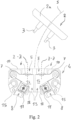
- numeral 1 generally designates an electrical safety contact with a removable bridge 2 according to the invention.
- the removable contact bridge 2 comprises rod-like contacts 3 which are in electrical communication with each other and project parallel to each other from the same side of a head 2a of the removable bridge 2.
- the electrical safety contact 1 comprises a receiving hollow body 4 intended to be secured to an external support by means of fastening means.
- the receiving body 4 identifies an internal cavity 14 and has the shape of a parallelepiped defined by:
- the receiving body 4 is a body having the shape of a rectangular or square parallelepiped.
- the receiving body 4 comprises a first side wall 10 with two passing-through openings 5, extending along a predetermined axis Z-Z, formed therein.
- passing-through openings 5 are located substantially at the contact elements 6 and allow insertion/disconnection of the rod-like contacts 3 of the contact bridge 2 into/from the receiving body 4 along a predetermined insertion path (see broken line S of Figure 2 ).
- contact elements 6 it should be noted that these contact elements are supported in a well-known manner in the receiving body 4 so that, upon insertion of the aforementioned rod-like contacts 3 of the contact bridge 2 through the passing-through openings 5, these contact elements 6 are reversibly retracted into the receiving body 4, against the elastic return action exerted by the respective contact springs 7 which support them, to move from a forward position (see Figures 2 and 4 ), in which said contact elements 6 are substantially at their respective through openings 5, to a more retracted position inside the receiving body 6 (see Figure 1 ).
- each of the two aforementioned contact springs 7 is a thin leaf spring having a reduced thickness, approximately ranging from 0.10 to 0.20 mm, having a width approximately ranging from 5 to 10 mm, preferably of 7 mm.
- the receiving body 4 is a closed body and preferably comprises, in addition to the aforementioned passing-through openings 5 for insertion and disconnection of the rod-like contacts 3 of the contact bridge 2 into/from the receiving body 4, two additional passing-through openings 8 to allow electric conductors to be introduced into the receiving body 4 to their respective wiring terminals 11.
- Each wiring terminal is connected in electrical continuity with a respective contact element 6.
- the aforementioned springs 7 are made of an electrically conductive material, so that electrical continuity between each contact element 6 and its respective wiring terminal 11 will be provided by the contact leaf spring 7.
- the aforementioned receiving body 4 comprises at least one drain opening 13 to allow liquids and/or dirt to pass and exit from the cavity 14 of said receiving body 4, whereby a drain channel extending from the aforementioned first passing-through openings 5 to the aforementioned at least one drain opening 13 is identified in said receiving body.
- the aforementioned at least one drain opening 13 is positioned at a wall 15 that identifies one side of the receiving body 4 opposite to the side identified by the aforementioned first wall 10 having first passing-through openings (5).
- the aforementioned at least one drain opening 13 is positioned at a wall 15 of said receiving body 4 that identifies a side of said receiving body 4 parallel to the side identified by said one first wall 10 having first passing-through openings 5.
- the aforementioned at least one drain opening 13 identifies a passage which, when said electrical safety contact is in use, has a minimum free cross-section of at least 4 mm 2 , more preferably a minimum free cross-section of at least 6 mm 2 , to ensure drainage of any liquids and escape of any dirt.
- the aforementioned first passing-through openings 5 and the aforementioned at least one drain opening 13 are formed at with distinct side walls 10,15 of said receiving hollow body 4.
- said at least one drain opening 13 identifies a passage:
- said at least one drain opening 13 comprises two distinct drain openings 13.
- the receiving body 4 comprises a dividing partition 16 to divide the internal cavity 14 into two separate chambers, a respective spring 7 and a respective contact element 6 being accommodated inside each of said chambers.
- each of said two separate chambers is formed with at least one respective drain opening 13.
- the electrical safety contact with a removable contact bridge of the present invention fulfills the above mentioned need and also obviates the prior art drawbacks as set out in the introduction of this disclosure.
- the characteristic of providing said at least one drain opening can ensure the escape of any liquids or dirt in the internal compartment of the receiving body from the electrical safety contact through the first passing-through openings formed to allow insertion of the rod-like contacts 3 of the contact bridge.
- this is particularly useful when the electrical safety contact is positioned, for example, in the elevator structure, so that the aforementioned first passing-through openings, provided to allow insertion of the rod-like contacts of the contact bridge, will face upwards.
- any dirt or liquids will apparently tend to enter by gravity the internal compartment of the receiving body and, still by gravity, will travel along the aforementioned drain channel which extends from such first passing-through openings to the aforementioned at least one drain opening, thereby exiting the internal cavity of the receiving body.
- the openings formed for insertion of the electric conductors would not be useful for this purpose since, in operation, the presence of the electric wiring terminals and the electric conductors wired to these terminals would reduce the passage section thereby preventing or hindering the escape of dirt or liquids.
- the aforementioned drain channel identified in the receiving body between the first passing-through openings and the aforementioned at least one drain opening is distinct and does not extend through said wiring terminals to prevent oxidation phenomena of the conductive parts of said wiring terminals during operation.
- a further advantage of the electrical safety contact with a removable bridge of the present invention is its unique structural simplicity.
Landscapes
- Connector Housings Or Holding Contact Members (AREA)
- Details Of Connecting Devices For Male And Female Coupling (AREA)
- Investigating Or Analyzing Materials By The Use Of Electric Means (AREA)
- Food-Manufacturing Devices (AREA)
- Instruments For Viewing The Inside Of Hollow Bodies (AREA)
- Dry Shavers And Clippers (AREA)
Claims (12)
- Elektrischer Sicherheitskontakt mit einer lösbaren Kontaktbrücke, umfassend einen Aufnahmekörper (4), der einen inneren Hohlraum (14) identifiziert, in dem Kontaktelemente (6) in einer geschützten Position aufgenommen sind, die von entsprechenden Federn (7) gestützt werden und in elektrischer Kontinuität mit entsprechenden Verdrahtungsklemmen (11) für elektrische Leiter stehen, wobei:- der Aufnahmekörper (4) eine erste Wand (10) umfasst, die mit ersten Durchgangsöffnungen (5) mit vorbestimmter Achse (Z-Z) versehen ist, die an den Kontaktelementen (6) positioniert sind, um das Einsetzen oder das Trennen von stabförmigen Kontakten (3) einer Kontaktbrücke (2) in der Axialrichtung (Z-Z) der ersten Durchgangsöffnungen (5) zu ermöglichen,dadurch gekennzeichnet, dass der Aufnahmekörper (4) mindestens eine Abflussöffnung (13) umfasst, um Flüssigkeiten und/oder Schmutz zu ermöglichen, durch den inneren Hohlraum (14) des Aufnahmekörpers (4) zu gehen und aus dem inneren Hohlraum (14) des Aufnahmekörpers (4) auszutreten, wobei ein Abflusskanal in dem Aufnahmekörper identifiziert ist, der sich von den ersten Durchgangsöffnungen (5) zu der mindestens einen Abflussöffnung (13) erstreckt, wobei die mindestens eine Abflussöffnung (13) einen Durchgang identifiziert, der bei Verwendung des elektrischen Sicherheitskontakts einen freien Mindestquerschnitt von mindestens 4 mm2 aufweist, um den Abfluss von Flüssigkeiten und den Austritt von Schmutz zu gewährleisten.
- Elektrischer Sicherheitskontakt nach Anspruch 1, wobei die mindestens eine Abflussöffnung (13) an einer Wand (15) positioniert ist, die eine Seite des Aufnahmekörpers (4) identifiziert, die der Seite gegenüberliegt, die von der einen ersten Wand (10) identifiziert wird, die mit ersten Durchgangsöffnungen (5) versehen ist.
- Elektrischer Sicherheitskontakt nach Anspruch 1 oder 2, wobei die mindestens eine Abflussöffnung (13) an einer Wand (15) positioniert ist, die eine Seite des Aufnahmekörpers (4) identifiziert, die parallel zu der Seite ist, die von der ersten Wand (10) identifiziert wird, die mit ersten Durchgangsöffnungen (5) versehen ist.
- Elektrischer Sicherheitskontakt nach einem der Ansprüche 1 bis 3, dadurch gekennzeichnet, dass die mindestens eine Abflussöffnung (13) einen Durchgang identifiziert, der bei Verwendung des elektrischen Sicherheitskontakts einen freien Mindestquerschnitt von mindestens 6 mm2 aufweist, um den Abfluss von Flüssigkeiten und den Austritt von Schmutz zu gewährleisten.
- Elektrischer Sicherheitskontakt nach einem der Ansprüche 1 bis 4, wobei:- der Aufnahmehohlkörper (4) folgendes umfasst: eine hintere Bodenwand (9), Seitenwände, die aus der Bodenwand vorstehen und eine an den Seitenwänden befestigte Vorderwand (12), die die Funktion eines Verschlussdeckels des Aufnahmehohlkörpers (4) aufweist und- die ersten Durchgangsöffnungen (5) und die mindestens eine Abflussöffnung (13) an unterschiedlichen Seitenwänden (10, 15) des Aufnahmehohlkörpers (4) ausgebildet sind.
- Elektrischer Sicherheitskontakt nach einem der Ansprüche 1 bis 5, wobei die mindestens eine Abflussöffnung (13) einen Durchgang identifiziert, der:- sich über einen Axialabschnitt innen des Aufnahmekörpers (4) erstreckt und- durch innere Seitenwände (18) über die Gesamtlänge des erstreckten Durchgangs p innen des Aufnahmekörpers (4) begrenzt ist.
- Elektrischer Sicherheitskontakt nach einem der Ansprüche 1 bis 6, wobei die mindestens eine Abflussöffnung (13) zwei getrennte Abflussöffnungen (13) umfasst.
- Elektrischer Sicherheitskontakt nach einem der Ansprüche 1 bis 7, wobei:- der Aufnahmekörper (4) eine Trennwand (16), um den Hohlraum (14) in zwei getrennte Kammern zu teilen, eine jeweilige Feder (7) und ein jeweiliges Kontaktelement (6), die in jeder der Kammern aufgenommen sind, aufweist und- jede der beiden getrennten Kammern mit mindestens einer entsprechenden Abflussöffnung (13) versehen ist.
- Elektrischer Sicherheitskontakt nach einem der Ansprüche 1 bis 8, wobei der Aufnahmekörper (4) zweite Durchgangsöffnungen (8) aufweist, die geeignet sind, das Einführen von elektrischen Leitern in den Aufnahmekörper (4) bis zum Erreichen der Verdrahtungsklemmen (11) zu ermöglichen.
- Elektrischer Sicherheitskontakt nach einem der Ansprüche 1 bis 9, wobei:- die Federn (7) aus elektrisch leitfähigem Material hergestellt werden und- die elektrische Kontinuität zwischen einem Kontaktelement (6) und einer entsprechenden Verdrahtungsklemme (11) durch eine entsprechende der Federn (7) sichergestellt wird.
- Elektrischer Sicherheitskontakt nach einem der Ansprüche 1 bis 10, umfassend eine lösbare Brücke (3) aufweisend stangenförmige Kontakten (3), die in elektrischer Verbindung miteinander stehen und die parallel zueinander aus derselben Seite eines Kopfes (2a) der lösbaren Brücke (2) vorstehen, wobei die stangenförmigen Kontakte (3) durch die ersten Öffnungen (5) lösbar in den Aufnahmekörper (4) eingeführt werden/eingeführt werden können, um eine elektrische Kontinuität zwischen den Kontaktelementen (6) festzulegen.
- Elektrischer Sicherheitskontakt nach einem der Ansprüche 1 bis 11, wobei der in dem Aufnahmekörper (4) identifizierte Abflusskanal von den ersten Durchgangsöffnungen (5) zu der mindestens einen Abflussöffnung (13) getrennt ist und nicht durch die Verdrahtungsklemmen (11) geht, um zu verhindern, dass Oxidationserscheinigungen an den leitenden Teilen der Verdrahtungsklemmen (11) beim Gebrauch auftreten.
Applications Claiming Priority (2)
| Application Number | Priority Date | Filing Date | Title |
|---|---|---|---|
| IT102020000032960A IT202000032960A1 (it) | 2020-12-31 | 2020-12-31 | Contatto elettrico di sicurezza con ponte di contatto asportabile |
| PCT/IB2021/062459 WO2022144820A1 (en) | 2020-12-31 | 2021-12-30 | An electrical safety contact with removable contact bridge |
Publications (3)
| Publication Number | Publication Date |
|---|---|
| EP4272286A1 EP4272286A1 (de) | 2023-11-08 |
| EP4272286C0 EP4272286C0 (de) | 2025-03-05 |
| EP4272286B1 true EP4272286B1 (de) | 2025-03-05 |
Family
ID=75252658
Family Applications (1)
| Application Number | Title | Priority Date | Filing Date |
|---|---|---|---|
| EP21851631.8A Active EP4272286B1 (de) | 2020-12-31 | 2021-12-30 | Elektrischer sicherheitskontakt mit abnehmbarer kontaktbrücke |
Country Status (4)
| Country | Link |
|---|---|
| EP (1) | EP4272286B1 (de) |
| CN (1) | CN116670060A (de) |
| IT (1) | IT202000032960A1 (de) |
| WO (1) | WO2022144820A1 (de) |
Families Citing this family (1)
| Publication number | Priority date | Publication date | Assignee | Title |
|---|---|---|---|---|
| WO2025082825A1 (de) * | 2023-10-20 | 2025-04-24 | Inventio Ag | Überbrückungsvorrichtung zum erzeugen eines kurzschlusses |
Family Cites Families (3)
| Publication number | Priority date | Publication date | Assignee | Title |
|---|---|---|---|---|
| US4722700A (en) * | 1987-01-23 | 1988-02-02 | Amp Incorporated | Low insertion force terminal for use with circuit panel |
| IT1403308B1 (it) * | 2011-01-18 | 2013-10-17 | Astra Srl | Contatto elettrico |
| CA3082618A1 (en) * | 2019-06-08 | 2020-12-08 | Norman R. Byrne | Electrical receptacle with drain-through feature |
-
2020
- 2020-12-31 IT IT102020000032960A patent/IT202000032960A1/it unknown
-
2021
- 2021-12-30 CN CN202180087727.6A patent/CN116670060A/zh active Pending
- 2021-12-30 EP EP21851631.8A patent/EP4272286B1/de active Active
- 2021-12-30 WO PCT/IB2021/062459 patent/WO2022144820A1/en not_active Ceased
Also Published As
| Publication number | Publication date |
|---|---|
| WO2022144820A1 (en) | 2022-07-07 |
| IT202000032960A1 (it) | 2022-07-01 |
| CN116670060A (zh) | 2023-08-29 |
| EP4272286A1 (de) | 2023-11-08 |
| EP4272286C0 (de) | 2025-03-05 |
Similar Documents
| Publication | Publication Date | Title |
|---|---|---|
| EP2987175B1 (de) | Elektrische schaltanordnung | |
| CN110581469B (zh) | 锁定结构、电气连接箱以及线束 | |
| US10566741B2 (en) | Shielded connector | |
| US3942143A (en) | Electromagnetic switching apparatus, particularly motor contactor, with auxiliary contacts | |
| JP7083701B2 (ja) | ロック構造、電気接続箱及びワイヤハーネス | |
| CZ285268B6 (cs) | Přerušovací sestava pro vypínač | |
| CN111201678B (zh) | 连接器 | |
| KR880005640A (ko) | 상호 교환가능한 전자개폐 스위치장치 | |
| WO2022144820A1 (en) | An electrical safety contact with removable contact bridge | |
| US6784393B2 (en) | Arc quenching device for low-voltage switching devices | |
| EP2871657B1 (de) | Schutzschalter mit gegossenem Gehäuse | |
| US2072729A (en) | Safety switch | |
| CA2320782A1 (en) | Rack system for insertion of electrical printed circuit board assemblies | |
| JP4263851B2 (ja) | ラックアセンブリにフロント要素の心出し接触部品及び独立した受入れ接触部品、特に接触片を備えたプリント板用モジュールシステム | |
| US5984730A (en) | Waterproof electric plug with fuse holder | |
| KR101719138B1 (ko) | 콤팩트한 통전 구조를 가지는 조인트 커넥터 | |
| GB1568660A (en) | Electric current distributor | |
| CN108962641A (zh) | 可移除电流开关元件和包括其的电气开关设备 | |
| KR100662677B1 (ko) | 내부 차폐부를 갖는 전기 커넥터 | |
| CN111049080A (zh) | 电接线盒 | |
| KR20000016737A (ko) | 정전위의 방전 감쇠의 수단을 가지는 삽입형 인쇄 회로 모듈을위한 서브-랙 | |
| JP6275624B2 (ja) | 電気接続箱 | |
| KR20120070723A (ko) | 전자식릴레이 | |
| US20230016517A1 (en) | Auxiliary contact unit | |
| EP1178572B1 (de) | Anschlussklemme für Leiterplatten |
Legal Events
| Date | Code | Title | Description |
|---|---|---|---|
| STAA | Information on the status of an ep patent application or granted ep patent |
Free format text: STATUS: UNKNOWN |
|
| STAA | Information on the status of an ep patent application or granted ep patent |
Free format text: STATUS: THE INTERNATIONAL PUBLICATION HAS BEEN MADE |
|
| PUAI | Public reference made under article 153(3) epc to a published international application that has entered the european phase |
Free format text: ORIGINAL CODE: 0009012 |
|
| STAA | Information on the status of an ep patent application or granted ep patent |
Free format text: STATUS: REQUEST FOR EXAMINATION WAS MADE |
|
| 17P | Request for examination filed |
Effective date: 20230727 |
|
| AK | Designated contracting states |
Kind code of ref document: A1 Designated state(s): AL AT BE BG CH CY CZ DE DK EE ES FI FR GB GR HR HU IE IS IT LI LT LU LV MC MK MT NL NO PL PT RO RS SE SI SK SM TR |
|
| DAV | Request for validation of the european patent (deleted) | ||
| DAX | Request for extension of the european patent (deleted) | ||
| GRAP | Despatch of communication of intention to grant a patent |
Free format text: ORIGINAL CODE: EPIDOSNIGR1 |
|
| STAA | Information on the status of an ep patent application or granted ep patent |
Free format text: STATUS: GRANT OF PATENT IS INTENDED |
|
| INTG | Intention to grant announced |
Effective date: 20241219 |
|
| GRAS | Grant fee paid |
Free format text: ORIGINAL CODE: EPIDOSNIGR3 |
|
| GRAA | (expected) grant |
Free format text: ORIGINAL CODE: 0009210 |
|
| STAA | Information on the status of an ep patent application or granted ep patent |
Free format text: STATUS: THE PATENT HAS BEEN GRANTED |
|
| AK | Designated contracting states |
Kind code of ref document: B1 Designated state(s): AL AT BE BG CH CY CZ DE DK EE ES FI FR GB GR HR HU IE IS IT LI LT LU LV MC MK MT NL NO PL PT RO RS SE SI SK SM TR |
|
| REG | Reference to a national code |
Ref country code: GB Ref legal event code: FG4D |
|
| REG | Reference to a national code |
Ref country code: CH Ref legal event code: EP |
|
| REG | Reference to a national code |
Ref country code: DE Ref legal event code: R096 Ref document number: 602021027302 Country of ref document: DE |
|
| REG | Reference to a national code |
Ref country code: IE Ref legal event code: FG4D |
|
| U01 | Request for unitary effect filed |
Effective date: 20250401 |
|
| U07 | Unitary effect registered |
Designated state(s): AT BE BG DE DK EE FI FR IT LT LU LV MT NL PT RO SE SI Effective date: 20250407 |
|
| PG25 | Lapsed in a contracting state [announced via postgrant information from national office to epo] |
Ref country code: RS Free format text: LAPSE BECAUSE OF FAILURE TO SUBMIT A TRANSLATION OF THE DESCRIPTION OR TO PAY THE FEE WITHIN THE PRESCRIBED TIME-LIMIT Effective date: 20250605 |
|
| PG25 | Lapsed in a contracting state [announced via postgrant information from national office to epo] |
Ref country code: ES Free format text: LAPSE BECAUSE OF FAILURE TO SUBMIT A TRANSLATION OF THE DESCRIPTION OR TO PAY THE FEE WITHIN THE PRESCRIBED TIME-LIMIT Effective date: 20250305 |
|
| PG25 | Lapsed in a contracting state [announced via postgrant information from national office to epo] |
Ref country code: NO Free format text: LAPSE BECAUSE OF FAILURE TO SUBMIT A TRANSLATION OF THE DESCRIPTION OR TO PAY THE FEE WITHIN THE PRESCRIBED TIME-LIMIT Effective date: 20250605 |
|
| PG25 | Lapsed in a contracting state [announced via postgrant information from national office to epo] |
Ref country code: HR Free format text: LAPSE BECAUSE OF FAILURE TO SUBMIT A TRANSLATION OF THE DESCRIPTION OR TO PAY THE FEE WITHIN THE PRESCRIBED TIME-LIMIT Effective date: 20250305 |
|
| PG25 | Lapsed in a contracting state [announced via postgrant information from national office to epo] |
Ref country code: GR Free format text: LAPSE BECAUSE OF FAILURE TO SUBMIT A TRANSLATION OF THE DESCRIPTION OR TO PAY THE FEE WITHIN THE PRESCRIBED TIME-LIMIT Effective date: 20250606 |
|
| PG25 | Lapsed in a contracting state [announced via postgrant information from national office to epo] |
Ref country code: SM Free format text: LAPSE BECAUSE OF FAILURE TO SUBMIT A TRANSLATION OF THE DESCRIPTION OR TO PAY THE FEE WITHIN THE PRESCRIBED TIME-LIMIT Effective date: 20250305 |
|
| PG25 | Lapsed in a contracting state [announced via postgrant information from national office to epo] |
Ref country code: PL Free format text: LAPSE BECAUSE OF FAILURE TO SUBMIT A TRANSLATION OF THE DESCRIPTION OR TO PAY THE FEE WITHIN THE PRESCRIBED TIME-LIMIT Effective date: 20250305 |
|
| PG25 | Lapsed in a contracting state [announced via postgrant information from national office to epo] |
Ref country code: CZ Free format text: LAPSE BECAUSE OF FAILURE TO SUBMIT A TRANSLATION OF THE DESCRIPTION OR TO PAY THE FEE WITHIN THE PRESCRIBED TIME-LIMIT Effective date: 20250305 |
|
| PG25 | Lapsed in a contracting state [announced via postgrant information from national office to epo] |
Ref country code: SK Free format text: LAPSE BECAUSE OF FAILURE TO SUBMIT A TRANSLATION OF THE DESCRIPTION OR TO PAY THE FEE WITHIN THE PRESCRIBED TIME-LIMIT Effective date: 20250305 |
|
| PG25 | Lapsed in a contracting state [announced via postgrant information from national office to epo] |
Ref country code: IS Free format text: LAPSE BECAUSE OF FAILURE TO SUBMIT A TRANSLATION OF THE DESCRIPTION OR TO PAY THE FEE WITHIN THE PRESCRIBED TIME-LIMIT Effective date: 20250705 |
|
| PLBE | No opposition filed within time limit |
Free format text: ORIGINAL CODE: 0009261 |
|
| STAA | Information on the status of an ep patent application or granted ep patent |
Free format text: STATUS: NO OPPOSITION FILED WITHIN TIME LIMIT |
|
| REG | Reference to a national code |
Ref country code: CH Ref legal event code: L10 Free format text: ST27 STATUS EVENT CODE: U-0-0-L10-L00 (AS PROVIDED BY THE NATIONAL OFFICE) Effective date: 20260114 |
|
| U20 | Renewal fee for the european patent with unitary effect paid |
Year of fee payment: 5 Effective date: 20251223 |
|
| 26N | No opposition filed |
Effective date: 20251208 |