EP4270744A1 - Rotor, brushless motor, and method for manufacturing rotor - Google Patents
Rotor, brushless motor, and method for manufacturing rotor Download PDFInfo
- Publication number
- EP4270744A1 EP4270744A1 EP21910867.7A EP21910867A EP4270744A1 EP 4270744 A1 EP4270744 A1 EP 4270744A1 EP 21910867 A EP21910867 A EP 21910867A EP 4270744 A1 EP4270744 A1 EP 4270744A1
- Authority
- EP
- European Patent Office
- Prior art keywords
- magnet
- rotating shaft
- circumferential surface
- outer circumferential
- case
- Prior art date
- Legal status (The legal status is an assumption and is not a legal conclusion. Google has not performed a legal analysis and makes no representation as to the accuracy of the status listed.)
- Pending
Links
Images



Classifications
-
- H—ELECTRICITY
- H02—GENERATION; CONVERSION OR DISTRIBUTION OF ELECTRIC POWER
- H02K—DYNAMO-ELECTRIC MACHINES
- H02K1/00—Details of the magnetic circuit
- H02K1/06—Details of the magnetic circuit characterised by the shape, form or construction
- H02K1/22—Rotating parts of the magnetic circuit
- H02K1/27—Rotor cores with permanent magnets
- H02K1/2706—Inner rotors
- H02K1/272—Inner rotors the magnetisation axis of the magnets being perpendicular to the rotor axis
- H02K1/2726—Inner rotors the magnetisation axis of the magnets being perpendicular to the rotor axis the rotor consisting of a single magnet or two or more axially juxtaposed single magnets
-
- H—ELECTRICITY
- H02—GENERATION; CONVERSION OR DISTRIBUTION OF ELECTRIC POWER
- H02K—DYNAMO-ELECTRIC MACHINES
- H02K7/00—Arrangements for handling mechanical energy structurally associated with dynamo-electric machines, e.g. structural association with mechanical driving motors or auxiliary dynamo-electric machines
- H02K7/04—Balancing means
-
- H—ELECTRICITY
- H02—GENERATION; CONVERSION OR DISTRIBUTION OF ELECTRIC POWER
- H02K—DYNAMO-ELECTRIC MACHINES
- H02K15/00—Processes or apparatus specially adapted for manufacturing, assembling, maintaining or repairing of dynamo-electric machines
- H02K15/16—Centring rotors within the stators
- H02K15/165—Balancing the rotors
-
- H—ELECTRICITY
- H02—GENERATION; CONVERSION OR DISTRIBUTION OF ELECTRIC POWER
- H02K—DYNAMO-ELECTRIC MACHINES
- H02K11/00—Structural association of dynamo-electric machines with electric components or with devices for shielding, monitoring or protection
- H02K11/20—Structural association of dynamo-electric machines with electric components or with devices for shielding, monitoring or protection for measuring, monitoring, testing, protecting or switching
- H02K11/21—Devices for sensing speed or position, or actuated thereby
- H02K11/215—Magnetic effect devices, e.g. Hall-effect or magneto-resistive elements
-
- H—ELECTRICITY
- H02—GENERATION; CONVERSION OR DISTRIBUTION OF ELECTRIC POWER
- H02K—DYNAMO-ELECTRIC MACHINES
- H02K5/00—Casings; Enclosures; Supports
- H02K5/04—Casings or enclosures characterised by the shape, form or construction thereof
- H02K5/16—Means for supporting bearings, e.g. insulating supports or means for fitting bearings in the bearing-shields
- H02K5/173—Means for supporting bearings, e.g. insulating supports or means for fitting bearings in the bearing-shields using bearings with rolling contact, e.g. ball bearings
- H02K5/1732—Means for supporting bearings, e.g. insulating supports or means for fitting bearings in the bearing-shields using bearings with rolling contact, e.g. ball bearings radially supporting the rotary shaft at both ends of the rotor
Definitions
- the present invention relates to a rotor, a brushless motor, and a method for manufacturing the rotor.
- Patent Document 1 describes a brushless motor, in which a rotor made of a permanent magnet rotates when an electric current is passed through a coil wound around a field core, with a configuration integrally attaching holding bodies, each having a rotating shaft provided in a protruding manner on one end surface, to both end surfaces of the columnar rotor. Then, the holding body is bonded to each of both end surfaces of the columnar rotor.
- the holding bodies in Patent Document 1 are integrally attached to both end surfaces of the rotor by crimping both end portions of the sleeve to the end surfaces of the holding bodies inserted into the sleeve together with the cylindrical rotor.
- Patent Document 1 Japanese Utility Model Application Laid-Open Publication No. 62-119182
- An object of the present invention is to provide a rotor, etc. that can suppress deterioration of a rotor balance even though the motor characteristics are improved.
- An object of the present invention is to provide a rotor, etc. that can suppress vibrations.
- the present invention completed under the above object provides a rotor rotatable around a predetermined centerline, including: a columnar magnet; and a rotating shaft with a shaft part and a cylindrical part, wherein an outer circumferential surface of the magnet and an inner circumferential surface of the cylindrical part of the rotating shaft are joined, and an end surface of the magnet in a direction of the centerline and an end surface of the rotating shaft in the direction of the centerline, which faces the end surface of the magnet, are not joined.
- outer circumferential surface of the magnet and the inner circumferential surface of the cylindrical part may be bonded.
- the magnet may include a concave part formed at an end portion in the direction of the centerline, the concave part being concaved as compared to a central outer circumferential surface of a central part, and the cylindrical part of the rotating shaft may be fitted over the concave part of the magnet.
- the present invention provides a brushless motor including: a stator; and the rotor rotatably provided inside the stator.
- the present invention provides a method for manufacturing a rotor rotatable around a predetermined centerline, the method including: a step of applying an adhesive agent on an outer circumferential surface of an end portion of a columnar magnet in a direction of the centerline; and a step of moving the magnet, on which the adhesive agent is applied, and a rotating shaft, which includes a shaft part and a cylindrical part, relative to each other in the direction of the centerline to fit the outer circumferential surface of the magnet into the cylindrical part of the rotating shaft, and thereby bonding the outer circumferential surface of the magnet and an inner circumferential surface of the cylindrical part of the rotating shaft with the adhesive agent.
- the present invention completed under the above object provides a rotor rotatable around a predetermined centerline, including: a columnar magnet; a magnet case covering at least a part of an outer circumferential surface of the magnet; and a rotating shaft with a shaft part and a cylindrical part, wherein the cylindrical part of the rotating shaft covers an outer circumferential surface of an end portion of the magnet case in a direction of the centerline.
- the magnet case may be press-fitted over the magnet, and may include a concave part on the outer circumferential surface of the end portion in the direction of the centerline, the concave part being concaved toward the centerline as compared to an outer circumferential surface of a central part, and the cylindrical part of the rotating shaft may be press-fitted over the concave part.
- an outer circumferential surface of the concave part of the magnet case and an inner circumferential surface of the cylindrical part of the rotating shaft may be bonded.
- an end surface of the magnet in the direction of the centerline and an end surface of the rotating shaft in the direction of the centerline, which faces the end surface of the magnet may not be joined.
- the magnet case may include a case cylindrical part covering a part of the outer circumferential surface of the magnet, and a cover part covering an end surface of the magnet in the direction of the centerline.
- the cover part may include a through hole.
- the present invention provides a brushless motor including: a stator; and the rotor rotatably provided inside the stator.
- the present invention provides a method for manufacturing a rotor rotatable around a predetermined centerline, the method including: a step of press-fitting a columnar magnet into a magnet case covering at least a part of an outer circumferential surface of the magnet; a step of performing cutting processing on an outer circumferential surface of an end portion of the magnet case in a direction of the centerline to form a concave part concaved toward the centerline as compared to an outer circumferential surface of a central part; and a step of moving the magnet case and a rotating shaft, which includes a shaft part and a cylindrical part, relative to each other in the direction of the centerline to press-fit the concave part of the magnet case into the cylindrical part of the rotating shaft.
- the method may further include: a step of performing, in a state where the magnet case is press-fitted over the magnet, the cutting processing on an end surface of the magnet on one side in the direction of the centerline and an end surface of the magnet case on the one side in the direction of the centerline simultaneously.
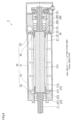
- FIG. 1 is a diagram showing an example of a cross section of a brushless motor 1 related to the first exemplary embodiment.
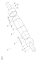
- FIG. 2 is a perspective view showing an example of components constituting a rotor 10 related to the first exemplary embodiment.
- the brushless motor 1 related to the exemplary embodiment includes a rotor 10, a stator 20, and a housing 30 that houses the stator 20.
- the rotor 10 includes a rotating shaft 11 and a magnet 12 that rotates integrally with the rotating shaft 11.
- the centerline direction of the rotating shaft 11 is simply referred to as an "axial direction" in some cases.
- the left side in FIG. 1 is referred to as “one side”
- the right side in FIG. 1 is referred to as “the other side” in some cases.
- the rotor 10 will be described in detail later.
- the stator 20 includes: a cylindrical coil 21; a cylindrical stack 22 holding the coil 21; a relay board 23 provided to an end surface on the other side of the stack 22; and a lead wire 24 connected to the relay board 23.
- the housing 30 includes: a cylindrical case 31, both end portions of which in the axial direction of the rotating shaft 11 open; a first plate 32 covering the opening on one side of the case 31; and a second plate 33 covering the opening on the other side of the case 31.
- the housing 30 also includes: a first bearing 34 held by the first plate 32 to rotatably support an end portion on one side of the rotating shaft 11; and a second bearing 35 held by the second plate 33 to rotatably support an end portion on the other side of the rotating shaft 11.
- the first plate 32 and the second plate 33 are substantially cylindrical members that hold the first bearing 34 and the second bearing 35 inside thereof, respectively, and are inserted into the case 31.
- the first bearing 34 and the second bearing 35 can be exemplified as a ball bearing.
- the brushless motor 1 includes: a detection device 50 that is provided closer to the other side than the second bearing 35 and detects the rotation angle of the rotor 10; and a closed-end cylindrical cover 60 that covers the detection device 50.
- the detection device 50 includes: a magnetic sensor 51; a sensor substrate 52 on which the magnetic sensor 51 is mounted; and a magnet unit 54 with a sensor magnet 53 provided to face the magnetic sensor 51.
- the rotating shaft 11 includes: a first rotating shaft 70 attached to an end portion on the one side of the magnet 12; and a second rotating shaft 80 attached to an end portion on the other side of the magnet 12.
- the first rotating shaft 70 includes: a column-shaped first columnar part 71 provided on the one side; and a cylinder-shaped first cylindrical part 72 provided closer to the other side than the first columnar part 71.
- the first rotating shaft 70 also includes a first connection part 73 that connects the first columnar part 71 and the first cylindrical part 72.
- the second rotating shaft 80 includes: a column-shaped second columnar part 81 provided on the other side; and a cylinder-shaped second cylindrical part 82 provided closer to the one side than the second columnar part 81.
- the second rotating shaft 80 also includes a second connection part 83 that connects the second columnar part 81 and the second cylindrical part 82.
- a first concave part 911 which is concaved as compared to a central outer circumferential surface 931 of a central part 93, is formed at a first end portion 91, which is an end portion on the one side in the axial direction.
- a second concave part 921 which is concaved as compared to the central outer circumferential surface 931 of the central part 93, is formed at a second end portion 92, which is an end portion on the other side in the axial direction.
- a chamfer 932 is formed at each of both end portions of the central part 93 in the axial direction.
- the magnet 12 is shaped by performing cutting processing for the first concave part 911 and the second concave part 921, performing cutting processing for a first end surface 912 of the first end portion 91 and a second end surface 922 of the second end portion 92, and performing cutting processing for the chamfers 932 on a columnar material with a lathe.
- a first outer circumferential surface 913 of the first concave part 911 is parallel to the axial direction, and the diameter of the first outer circumferential surface 913 is smaller than the diameter of the central outer circumferential surface 931 of the central part 93.
- the second outer circumferential surface 923 of the second concave part 921 is parallel to the axial direction, and the diameter of the second outer circumferential surface 923 is smaller than the diameter of the central outer circumferential surface 931 of the central part 93. It can be exemplified that the diameter of the first outer circumferential surface 913 of the first concave part 911 and the diameter of the second outer circumferential surface 923 of the second concave part 921 are the same.
- the diameter of the outer circumferential surface of the first columnar part 71 of the first rotating shaft 70 is smaller than the diameter of the first outer circumferential surface 913 of the first concave part 911 in the magnet 12, and the diameter of a first inner circumferential surface 721 of the first cylindrical part 72 of the first rotating shaft 70 is slightly larger than the diameter of the first outer circumferential surface 913 of the first concave part 911 in the magnet 12. Then, the first rotating shaft 70 is assembled to the magnet 12 so that the first cylindrical part 72 covers part of the first outer circumferential surface 913 of the first concave part 911 in the magnet 12, and the first end surface 731 of the first connection part 73 is in contact with the first end surface 912 of the magnet 12. In other words, the first cylindrical part 72 of the first rotating shaft 70 and the first concave part 911 of the magnet are fitted.
- the first rotating shaft 70 and the magnet 12 are assembled, the first rotating shaft 70 and the magnet 12 are moved relative to each other in the axial direction in the state where the adhesive agent is applied on the first outer circumferential surface 913 of the first concave part 911 in the magnet 12.
- the first rotating shaft 70 is moved from the one side to the other side in the axial direction with respect to the magnet 12.
- the adhesive agent is then present at a gap between the first inner circumferential surface 721 of the first cylindrical part 72 of the first rotating shaft 70 and the first outer circumferential surface 913 of the first concave part 911 of the magnet 12, to thereby bond the first rotating shaft 70 and the magnet 12.
- part of the adhesive agent moves from the one side to the other side in the axial direction as the first rotating shaft 70 and the magnet 12 are moved relative to each other, and moves to a gap between a tip end portion of the first cylindrical part 72 and an end portion on the one side of the central part 93 or the chamfer 932.
- the adhesive agent moved into the gap is removed as needed, for example, by wiping.
- the diameter of the outer circumferential surface of the second columnar part 81 of the second rotating shaft 80 is smaller than the diameter of the second outer circumferential surface 923 of the second concave part 921 in the magnet 12, and the diameter of a second inner circumferential surface 821 of the second cylindrical part 82 of the second rotating shaft 80 is slightly larger than the diameter of the second outer circumferential surface 923 of the second concave part 921 in the magnet 12.
- the second rotating shaft 80 is assembled to the magnet 12 so that the second cylindrical part 82 covers part of the second outer circumferential surface 923 of the second concave part 921 in the magnet 12, and the second end surface 831 of the second connection part 83 is in contact with the end surface on the other side of the magnet 12.
- the second cylindrical part 82 of the second rotating shaft 80 and the second concave part 921 of the magnet are fitted.
- the second rotating shaft 80 and the magnet 12 are assembled, the second rotating shaft 80 and the magnet 12 are moved relative to each other in the axial direction in the state where the adhesive agent is applied on the second outer circumferential surface 923 of the second concave part 921 in the magnet 12.
- the second rotating shaft 80 is moved from the other side to the one side in the axial direction with respect to the magnet 12.
- the adhesive agent is then present at a gap between the second inner circumferential surface 821 of the second cylindrical part 82 of the second rotating shaft 80 and the second outer circumferential surface 923 of the second concave part 921 of the magnet 12, to thereby bond the second rotating shaft 80 and the magnet 12.
- part of the adhesive agent moves from the other side to the one side in the axial direction as the second rotating shaft 80 and the magnet 12 are moved relative to each other, and moves to a gap between a tip end portion of the second cylindrical part 82 and an end portion or the chamfer 932 on the other side of the central part 93.
- the adhesive agent moved into the gap is removed as needed, for example, by wiping.
- the brushless motor 1 configured as described above includes the stator 20 and the rotor 10 rotatably provided inside the stator 20.
- the rotor 10 then includes the columnar magnet 12, and the rotating shaft 11 with a shaft part (for example, the first columnar part 71) and a cylinder-shaped cylindrical part (for example, the first cylindrical part 72) that covers part of the outer circumferential surface of the magnet 12 (for example, the first outer circumferential surface 913).
- the outer circumferential surface of the magnet 12 (for example, the first outer circumferential surface 913) and an inner circumferential surface (for example, the first inner circumferential surface 721) of the cylindrical part of the rotating shaft 11 (for example, the first cylindrical part 72) are joined, and the end surface (for example, the first end surface 912) of the magnet 12 in the axial direction and the end surface of the rotating shaft 11 in the axial direction, which is an end surface (for example, the first end surface 731) facing the end surface (for example, the first end surface 912) of the magnet 12 in the axial direction, are not joined. Therefore, the center of the rotating shaft 11 and the centerline of the magnet 12 coincide with ease.
- the outer circumferential surface (for example, the first outer circumferential surface 913) of the magnet 12 and the inner circumferential surface (for example, the first inner circumferential surface 721) of the cylindrical part (for example, the first cylindrical part 72) of the rotating shaft 11 are bonded.
- bonding the magnet 12 and the rotating shaft 11 makes it easier for the magnet 12 and the rotating shaft 11 to rotate in one piece.
- the magnet 12 and the rotating shaft 11 can be easily integrated.
- the method of joining the magnet 12 and the rotating shaft 11 is not limited to bonding.
- the magnet 12 and the rotating shaft 11 may be adhered to each other.
- the magnet 12 and the rotating shaft 11 may also be welded.
- the magnet 12 for example, the first outer circumference surface 913
- the rotating shaft 11 for example, the first inner circumference surface 721
- a concave part (for example, the first concave part 911) concaved as compared to the central outer circumferential surface 931 of the central part 93 is formed at the end portion (for example, the first end portion 91) of the rotating shaft 11 in the axial direction, and the cylindrical part (for example, the first cylindrical part 72) of the rotating shaft 11 is fitted over the concave part (for example, the first concave part 911) of the magnet 12.
- the outer diameter of the central outer circumferential surface 931 of the central part 93 of the magnet 12 and the outer diameters of the outer circumferential surfaces of the first cylindrical part 72 and the second cylindrical part 82 of the rotating shaft 11 should be the same. This makes it possible to reduce an air gap between the central outer circumferential surface (for example, the central outer circumferential surface 931) of the magnet 12 and the coil 21 of the stator 20, as compared to, for example, the case in which the diameters of the outer circumferential surfaces of the first cylindrical part 72 and the second cylindrical part 82 of the rotating shaft 11 are larger than the diameter of the central outer circumferential surface 931 of the central part 93 of the magnet 12.
- the diameters of the outer circumferential surfaces of the first cylindrical part 72 and the second cylindrical part 82 of the rotating shaft 11 are smaller than the diameter of the central outer circumferential surface 931 of the central part 93 of the magnet 12, and the thicknesses of the first cylindrical part 72 and the second cylindrical part 82 are the same, it is possible to reduce an air gap between the first outer circumferential surface 913 of the first concave part 911, the second outer circumferential surface 923 of the second concave part 921 and the coil 21.
- the magnetic flux density of the air gap can be increased; thereby the rotation performance of the brushless motor 1 can be improved.
- first columnar part 71 of the first rotating shaft 70 and the second columnar part 81 of the second rotating shaft 80 of the rotating shaft 11, which are rotatably supported by the first bearing 34 and the second bearing 35, respectively, are not limited to the columnar part.
- first columnar part 71 and the second columnar part 81 may be cylindrical.
- fitting between the first cylindrical part 72 of the first rotating shaft 70 and the first concave part 911 of the magnet 12 is not limited to a clearance fit, and the fitting may be a transition fit or an interference fit.
- fitting between the second cylindrical part 82 of the second rotating shaft 80 and the second concave part 921 of the magnet 12 is not limited to the clearance fit, and the fitting may be the transition fit or the interference fit.
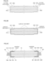
- FIG. 3 is a diagram showing an example of the method for manufacturing the rotor 10.
- a columnar material of the magnet 12 is subjected to cutting processing with a lathe to shape the first concave part 911 and the second concave part 921, the first end surface 912 and the second end surface 922, and the chamfers 932.
- the adhesive agent is applied on the first outer circumferential surface 913 of the first concave part 911 of the magnet 12, and the first cylindrical part 72 of the first rotating shaft 70 is fitted over the first concave part 911. Consequently, the magnet 12 and the first rotating shaft 70 are bonded by the adhesive agent.
- the adhesive agent is applied on the second outer circumferential surface 923 of the second concave part 921 of the magnet 12, and the second cylindrical part 82 of the second rotating shaft 80 is fitted over the second concave part 921. Consequently, the magnet 12 and the second rotating shaft 80 are bonded by the adhesive agent.
- the position where the adhesive agent is applied may be on the first inner circumferential surface 721 of the first cylindrical part 72 of the first rotating shaft 70; however, if the adhesive agent is applied to the position, when the first cylindrical part 72 of the first rotating shaft 70 is fitted over the magnet 12, there is a risk that the adhesive agent adheres to the end surface 912 of the magnet 12; accordingly, the position where the adhesive agent is applied is preferably on the first outer circumferential surface 913 of the first concave part 911 of the magnet 12, as described above.
- the manufacturing method of the rotor 10 includes a step of performing the cutting processing on the end portion of the columnar magnet 12 in the centerline direction to form the concave part (for example, the first concave part 911) concaved as compared to the central outer circumferential surface 931 of the central part 93.
- the manufacturing method of the rotor 10 also includes a step of applying the adhesive agent on the concave part (for example, the first concave part 911), and a step of moving the magnet 12, on which the adhesive agent has been applied, relative to the rotating shaft (for example, the first rotating shaft 70) in the centerline direction to fit the cylindrical part (for example, the first cylindrical part 72) over the concave part (for example, the first concave part 911).
- an outer concave part 732 which is concaved from the first end surface 731, is formed at an outer circumferential part on the first end surface 731 of the first connection part 73. Due to surface treatment such as nickel plating applied to the magnet 12, the outer concave part 732 is shaped to prevent a convex part protruding in the axial direction from the first end surface 912 shaped at an intersecting part of the first end surface 912 and the first outer circumferential surface 913 of the magnet 12 from contacting the first end surface 731 of the first rotating shaft 70. Similarly, in the second rotating shaft 80, an outer concave part 832, which is concaved from the second end surface 831, is formed at an outer circumferential part on the second end surface 831 of the second connection part 83.
- a central concave part 733 concaved from the first end surface 731 is formed at the central part of the first end surface 731 of the first connection part 73. Due to the first end surface 912 of the magnet 12 being formed by cutting processing with the lathe, the central concave part 733 is shaped to prevent a convex part protruding in the axial direction from the central part of the first end surface 912 formed at the first end surface 912 from contacting the first end surface 731 of the first rotating shaft 70. Similarly, in the second rotating shaft 80, a central concave part 833 concaved from the second end surface 831 is formed at the central part of the second end surface 831 of the second connection part 83.
- the chamfers 932 of the magnet 12 are shaped to prevent the magnets 12 from being damaged even though the magnets contact with each other when the magnets 12 subjected to the cutting processing are transported for the surface treatment, or during application of the surface treatment.
- the chamfers 932 do not have to be shaped.
- FIG. 4 is a diagram showing an example of a cross section of a brushless motor 2 related to the second exemplary embodiment.
- the brushless motor 2 related to the second exemplary embodiment is different in a rotor 210, which corresponds to the rotor 10, from the brushless motor 1 related to the first exemplary embodiment.
- a rotor 210 which corresponds to the rotor 10
- description will be given to the points that are different from the first exemplary embodiment.
- the same reference signs will be used for the components having the same shape and functions, and detailed descriptions thereof will be omitted.
- the rotor 210 related to the second exemplary embodiment includes a rotating shaft 211 and a magnet 212 that rotates integrally with the rotating shaft 211.
- the magnet 212 is purely cylindrical, in which the first concave part 911 and the second concave part 921 are not formed. Therefore, the diameter of the outer circumferential surface 215 of the magnet 212 is the same from an end portion on the one side to an end portion on the other side in the axial direction.
- the rotating shaft 211 includes: a first rotating shaft 270 attached to an end portion on the one side of the magnet 212; and a second rotating shaft 280 attached to an end portion on the other side of the magnet 212.
- the first rotating shaft 270 includes: a first columnar part 71; and a cylinder-shaped first cylindrical part 272 provided closer to the other side than the first columnar part 71.
- the first rotating shaft 270 also includes a first connection part 273 that connects the first columnar part 71 and the first cylindrical part 272.
- the first cylindrical part 272 is fitted over the end portion on the one side of the magnet 212, and bonded to the magnet 212 with an adhesive agent. Since the first concave part 911 is not formed in the magnet 212, the first rotating shaft 270 differs from the first rotating shaft 70 related to the first exemplary embodiment in that the diameter of the outer circumferential surface of the first cylindrical part 272 is larger than the diameter of the outer circumferential surface 215 (including the outer circumferential surface of the central part) of the magnet 212.
- the second rotating shaft 280 includes: a second columnar part 81; and a cylinder-shaped second cylindrical part 282 provided closer to the one side than the second columnar part 81.
- the second rotating shaft 280 also includes a second connection part 283 that connects the second columnar part 81 and the second cylindrical part 282.
- the second cylindrical part 282 is fitted over the end portion on the other side of the magnet 212, and bonded to the magnet 212 with the adhesive agent. Since the second concave part 921 is not formed in the magnet 212, the second rotating shaft 280 differs from the second rotating shaft 80 related to the first exemplary embodiment in that the diameter of the outer circumferential surface of the second cylindrical part 282 is larger than the diameter of the outer circumferential surface 215 (including the outer circumferential surface of the central part) of the magnet 212.
- the brushless motor 2 configured as described above includes the stator 20 and the rotor 210 rotatably provided inside the stator 20.
- the rotor 210 then includes the columnar magnet 212, and the rotating shaft 211 with a shaft part (for example, the first columnar part 71) and a cylinder-shaped cylindrical part (for example, the first cylindrical part 272) that covers part of the outer circumferential surface 215 of the magnet 212.
- the outer circumferential surface 215 of the magnet 212 and an inner circumferential surface of the cylindrical part (for example, the first cylindrical part 272) of the rotating shaft 211 are joined, and the end surface of the magnet 212 in the axial direction and the end surface of the rotating shaft 211 in the axial direction, which is an end surface (for example, the end surface on the other side of the first connection part 273) facing the end surface of the magnet 212 in the axial direction, are not joined. Therefore, the center of the rotating shaft 211 and the centerline of the magnet 212 coincide with ease.
- FIG. 5 is a diagram showing an example of a cross section of a brushless motor 3 related to the third exemplary embodiment.
- FIG. 6 is a perspective view showing an example of components constituting a rotor 310 related to the third exemplary embodiment.
- the brushless motor 3 related to the exemplary embodiment includes the rotor 310, the stator 20, and a housing 30 that houses the stator 20.
- the rotor 310 includes a rotating shaft 311, a columnar magnet 312, and a cylindrical magnet case 313 covering the outer circumferential surface of the magnet 312.
- the magnet case 313 is press-fitted over the magnet 312, and the rotating shaft 311 is press-fitted over the magnet case 313.
- the centerline direction of the rotating shaft 311 is simply referred to as an "axial direction" in some cases.
- the left side in FIG. 5 is referred to as "one side”
- the right side in FIG. 5 is referred to as "the other side” in some cases.
- the rotor 310 will be described in detail later.
- the stator 20 includes: a cylindrical coil 21; a cylindrical stack 22 holding the coil 21; a relay board 23 provided to an end surface on the other side of the stack 22; and a lead wire 24 connected to the relay board 23.
- the housing 30 includes: a cylindrical case 31, both end portions of which in the axial direction of the rotating shaft 311 open; a first plate 32 covering the opening on one side in the case 31; and a second plate 33 covering the opening on the other side in the case 31.
- the housing 30 also includes: a first bearing 34 held by the first plate 32 to rotatably support an end portion on the one side of the rotating shaft 311; and a second bearing 35 rotatably supporting an end portion on the other side of the rotating shaft 311.
- the first plate 32 and the second plate 33 are substantially cylindrical members that hold the first bearing 34 and the second bearing 35 inside thereof, respectively, and are inserted into the case 31.
- the first bearing 34 and the second bearing 35 can be exemplified as a ball bearing.
- the brushless motor 3 includes: the detection device 50 that is provided closer to the other side than the second bearing 35 and detects the rotation angle of the rotor 310; and the closed-end cylindrical cover 60 that covers the detection device 50.
- the detection device 50 includes: a magnetic sensor 51; a sensor substrate 52 on which the magnetic sensor 51 is mounted; and a magnet unit 54 with a sensor magnet 53 provided to face the magnetic sensor 51.
- the rotating shaft 311 includes: a first rotating shaft 370 press-fitted over an end portion on the one side of the magnet case 313; and a second rotating shaft 380 press-fitted over an end portion on the other side of the magnet case 313.
- the first rotating shaft 370 includes: a column-shaped first columnar part 371 provided on the one side; and a cylinder-shaped first cylindrical part 372 provided closer to the other side than the first columnar part 371.
- the first rotating shaft 370 also includes a first connection part 373 that connects the first columnar part 371 and the first cylindrical part 372.
- the second rotating shaft 380 includes: a columnar-shaped second columnar part 381 provided on the other side; and a cylinder-shaped second cylindrical part 382 provided closer to the one side than the second columnar part 381.
- the second rotating shaft 380 also includes a second connection part 383 that connects the second columnar part 381 and the second cylindrical part 382.
- a first concave part 3911 is formed at a first end portion 391, which is an end portion on the one side in the axial direction.
- the first concave part 3911 is concaved as compared to a central outer circumferential surface 3931 of a central part 393.
- a second concave part 3921 is formed at a second end portion 392, which is an end portion on the other side in the axial direction.
- the second concave part 3921 is concaved as compared to the central outer circumferential surface 3931 of the central part 393.
- the magnet case 313 is shaped by performing cutting processing for the first concave part 3911 and the second concave part 3921 on a cylindrical material with a lathe.
- a first outer circumferential surface 3913 of the first concave part 3911 is a surface parallel to the axial direction, and the diameter of the first outer circumferential surface 3913 is smaller than the diameter of the central outer circumferential surface 3931 of the central part 393.
- the second outer circumferential surface 3923 of the second concave part 3921 is a surface parallel to the axial direction, and the diameter of the second outer circumferential surface 3923 is smaller than the diameter of the central outer circumferential surface 3931 of the central part 393. It can be exemplified that the diameter of the first outer circumferential surface 3913 of the first concave part 3911 and the diameter of the second outer circumferential surface 3923 of the second concave part 3921 are the same.
- the diameter of the outer circumferential surface of the first columnar part 371 of the first rotating shaft 370 is smaller than the diameter of the first outer circumferential surface 3913 of the first concave part 3911 of the magnet case 313.
- the diameter of the first inner circumference surface 3721 of the first cylindrical part 372 of the first rotating shaft 370 is slightly smaller than the diameter of the first outer circumferential surface 3913 of the first concave part 3911 of the magnet case 313.
- the first cylindrical part 372 is then fitted over the magnet case 313 with an interference fit.
- the first cylindrical part 372 may be fitted over the magnet case 313 with a transition fit.
- the first rotating shaft 370 is assembled to the magnet case 313 so that the first cylindrical part 372 covers part of the first outer circumferential surface 3913 of the first concave part 3911 in the magnet case 313, and the first end surface 3731 of the first connection part 373 is in contact with the first end surface 3122 of the magnet 312 and an end surface on the one side of the magnet case 313.
- the first end surface 3731 of the first connection part 373 of the first rotating shaft 370 is not joined to the first end surface 3122 of the magnet 312 and the end surface on the one side of the magnet case 313 by bonding, adhesion, welding, etc.
- the first rotating shaft 370 and the magnet case 313 are assembled, in the state where the adhesive agent is applied on the first outer circumferential surface 3913 of the first concave part 3911 in the magnet case 313, the first rotating shaft 370 and the magnet case 313 are moved relative to each other in the axial direction.
- the first rotating shaft 370 is moved from the one side to the other side in the axial direction with respect to the magnet case 313.
- the adhesive agent is then present between the first inner circumferential surface 3721 of the first cylindrical part 372 of the first rotating shaft 370 and the first outer circumferential surface 3913 of the first concave part 3911 of the magnet case 313, to thereby bond the first rotating shaft 370 and the magnet case 313.
- part of the adhesive agent moves from the one side to the other side in the axial direction as the first rotating shaft 370 and the magnet case 313 are moved relative to each other, and moves to a gap between a tip end portion of the first cylindrical part 372 and an end portion on the one side of the central part 393.
- the adhesive agent moved into the gap is removed as needed, for example, by wiping.
- the diameter of the outer circumferential surface of the second columnar part 381 of the second rotating shaft 380 is smaller than the diameter of the second outer circumferential surface 3923 of the second concave part 3921 of the magnet case 313.
- the diameter of the second inner circumferential surface 3821 of the second cylindrical part 382 of the second rotating shaft 380 is slightly smaller than the diameter of the second outer circumferential surface 3923 of the second concave part 3921 of the magnet case 313.
- the second cylindrical part 382 is then fitted over the magnet case 313 with the interference fit.
- the second cylindrical part 382 may be fitted over the magnet case 313 with the transition fit.
- the second rotating shaft 380 is assembled to the magnet case 313 so that the second cylindrical part 382 covers part of the second outer circumferential surface 3923 of the second concave part 3921 in the magnet case 313.
- the second end surface 3831 of the second connection part 383 of the second rotating shaft 380 and the end surface on the other side of the magnet case 313 are not joined to the second end surface 3123 of the magnet 312 and the end surface on the other side of the magnet case 313 by bonding, adhesion, welding, etc.
- the second rotating shaft 380 and the magnet case 313 are assembled, in the state where the adhesive agent is applied on the second outer circumferential surface 3923 of the second concave part 3921 in the magnet case 313, the second rotating shaft 380 and the magnet case 313 are moved relative to each other in the axial direction.
- the second rotating shaft 380 is moved from the other side to the one side in the axial direction with respect to the magnet case 313.
- the adhesive agent is then present between the second inner circumferential surface 3821 of the second cylindrical part 382 of the second rotating shaft 380 and the second outer circumferential surface 3923 of the second concave part 3921 of the magnet case 313, to thereby bond the second rotating shaft 380 and the magnet case 313.
- part of the adhesive agent moves from the other side to the one side in the axial direction as the second rotating shaft 380 and the magnet case 313 are moved relative to each other, and moves to a gap between a tip end portion of the second cylindrical part 382 and an end portion on the other side of the central part 393.
- the adhesive agent moved into the gap is removed as needed, for example, by wiping.
- the brushless motor 3 configured as described above includes the stator 20 and the rotor 310 rotatably provided inside the stator 20.
- the rotor 310 then includes: the columnar magnet 312; the magnet case 313 covering at least part of the outer circumferential surface of the magnet 312; and the rotating shaft 311 with a shaft part (for example, the first columnar part 371) and a cylinder-shaped cylindrical part (for example, the first cylindrical part 372) that covers part of the outer circumferential surface of the magnet case 313.
- the magnet case 313 is fitted over the magnet 312, and includes a concave part (for example, the first concave part 3911) at the end portion of the magnet 312 in the centerline direction, which is concaved toward the centerline as compared to the central part.
- the cylindrical part (for example, the first cylindrical part 372) of the rotating shaft 311 is press-fitted over the concave part (for example, the first concave part 3911) of the magnet case 313.
- the magnet case 313 is press-fitted over the magnet 312 and the rotating shaft 311 is press-fitted over the concave part (for example, the first concave part 3911) of the magnet case 313, dimensional variations or assembly errors among the components are reduced, and thereby the centerline of the rotating shaft 311 (the center of the rotation) and the centerline of the magnet 312 (the center of the rotation) coincide with ease.
- the brushless motor 3 the deflection and the amount of imbalance of the rotor 310 are reduced; therefore, the vibration can be suppressed.
- the magnet case 313 covers at least part of the outer circumferential surface of the magnet 312, damage to magnet 312 can be suppressed even though the rotor 310 is rotated at high speed, and rust generation can be suppressed even if the surface treatment such as nickel plating is not applied to the magnet 312.
- the cylindrical part (for example, the first cylindrical part 372) of the rotating shaft 311 covers the outer circumferential surface (for example, the first outer circumferential surface 3913) of the end portion of the magnet case 313 in the axial direction, even if the rotor 310 is rotated at high speed, occurrence of vibration due to deformation, etc.
- the end portion (for example, the first end portion 391) of the magnet case 313 in the axial direction can be suppressed.
- the end surface (for example, the first end surface 3122) of the magnet 312 in the axial direction and the end surface (for example, the first end surface 3731) of the rotating shaft 311 in the axial direction, which faces the above end surface are not joined, as compared to the case in which these end surfaces are joined, the inclination of the centerline of the magnet 312 with respect to the centerline of the rotating shaft 311 can be suppressed.
- the outer circumferential surface (for example, the first outer circumferential surface 3913) of the concave part (for example, the first concave part 3911) of the magnet case 313 and the inner circumferential surface (for example, the first inner circumferential surface 3721) of the cylindrical part (for example, the first cylindrical part 372) of the rotating shaft 311 are bonded.
- bonding the magnet case 313 and the rotating shaft 311 makes it easier for the magnet case 313 and the rotating shaft 311 to rotate in one piece.
- the magnet case 313 and the rotating shaft 311 can be easily integrated.
- the method of joining the magnet case 313 and the rotating shaft 311 is not limited to bonding.
- the magnet case 313 and the rotating shaft 311 may be adhered to each other.
- the magnet case 313 and the rotating shaft 311 may also be welded.
- the magnet case 313 is cylindrical and includes a concave part (for example, the first concave part 3911) at the end portion in the centerline direction. Consequently, the rotating shaft 311 can be easily press-fitted over the magnet case 313.
- the outer diameter of the central outer circumferential surface 3931 of the central part 393 of the magnet case 313 and the outer diameters of the outer circumferential surfaces of the first cylindrical part 372 and the second cylindrical part 382 of the rotating shaft 311 should be the same. This makes it possible to reduce an air gap between the magnet 312 and the coil 21 of the stator 20, as compared to, for example, the case in which the diameters of the outer circumferential surfaces of the first cylindrical part 372 and the second cylindrical part 382 of the rotating shaft 311 are larger than the diameter of the central outer circumferential surface 3931 of the central part 393 of the magnet case 313. As a result, the magnetic flux density of the air gap can be increased; thereby the rotation performance of the brushless motor 3 can be improved.
- first columnar part 371 of the first rotating shaft 370 and the second columnar part 381 of the second rotating shaft 380 of the rotating shaft 311, which are rotatably supported by the first bearing 34 and the second bearing 35, respectively, are not limited to the columnar part.
- first columnar part 371 and the second columnar part 381 may be cylindrical.
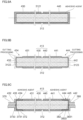
- FIG. 7 is a diagram showing an example of a method for manufacturing the rotor 310 related to the third exemplary embodiment.
- an adhesive agent is applied on the outer circumferential surface 3121 of the columnar magnet 312, and the magnet 312 is fitted (press-fitted) into the cylindrical material of the magnet case 313 with the interference fit.
- the cutting processing is applied to the cylindrical material of the magnet case 313 with a lathe to shape the first concave part 3911 and the second concave part 3921.
- the cutting processing is applied to shape the first end surface 3122 and the second end surface 3123 of the magnet 312, and at the same time, the cutting processing is also applied to shape the end surface on the one side and the end surface on the other side of the magnet case 313. This accurately flattens both end surfaces of the magnet 312 and the magnet case 313 in the axial direction.
- the adhesive agent is applied on the first outer circumferential surface 3913 of the first concave part 3911 of the magnet case 313, and the first cylindrical part 372 of the first rotating shaft 370 is fitted (press-fitted) over the first concave part 3911 with the interference fit. Consequently, the magnet case 313 and the first rotating shaft 370 are bonded by the adhesive agent.
- the adhesive agent is applied on the second outer circumferential surface 3923 of the second concave part 3921 of the magnet case 313, and the second cylindrical part 382 of the second rotating shaft 380 is fitted (press-fitted) over the second concave part 3921 with the interference fit. Consequently, the magnet case 313 and the second rotating shaft 380 are bonded by the adhesive agent.
- the manufacturing method of the rotor 310 includes: a step of press-fitting the magnet case 313 covering at least part of the outer circumferential surface of the magnet 312 over the columnar magnet 312; and a step of performing the cutting processing onto the end portions of the magnet case 313 in the centerline direction to form the concave parts (for example, the first concave part 3911) concaved as compared to the outer circumferential surface of the central part 393 (for example, the central outer circumferential surface 3931).
- the manufacturing method of the rotor 310 also includes: a step of moving the magnet case 313 and the rotating shaft 311 with the shaft part (for example, the first columnar part 371) and the cylinder-shaped cylindrical part (for example, the first cylindrical part 372) relative to each other in the centerline direction to press-fit the concave part (for example, the first concave part 3911) of the magnet case 313 into the cylindrical part (for example, the first cylindrical part 372) of the rotating shaft 311.
- the magnet case 313 is press-fitted over the magnet 312 and the rotating shaft 311 is press-fitted over the concave part (for example, the first concave part 3911) of the magnet case 313, dimensional variations or assembly errors among the components can be reduced, and the centerline of the rotating shaft 311 (the center of the rotation) and the centerline of the magnet 312 (the center of the rotation) can coincide with ease.
- the brushless motor 3 the deflection and the amount of imbalance of the rotor 310 are reduced; therefore, the vibration can be suppressed.
- a central concave part 3733 which is concaved from the first end surface 3731, is formed at the central part of the first end surface 3731 of the first connection part 373.
- the central concave part 3733 is shaped to prevent a convex part, which is possibly generated due to the cutting processing applied on the first end surface 3122 of the magnet 312 with the lathe, protruding in the axial direction from the central part of the first end surface 3122 from contacting the first end surface 3731.
- a central concave part 3833 which is concaved from the second end surface 3831, is formed at the central part of the second end surface 3831 of the second connection part 383.
- FIG. 8 is a diagram showing an example of a cross section of a brushless motor 4 related to the fourth exemplary embodiment.
- the brushless motor 4 related to the fourth exemplary embodiment is different in a rotor 410, which corresponds to the rotor 310, from the brushless motor 3 related to the third exemplary embodiment.
- description will be given to the points that are different from the third exemplary embodiment.
- the same reference signs will be used for the components having the same shape and functions, and detailed descriptions thereof will be omitted.
- the rotor 410 related to the fourth exemplary embodiment includes the rotating shaft 311, the magnet 312, and a magnet case 413 covering part of the outer circumferential surface 3121 of the magnet 312, the first end surface 3122 and the second end surface 3123.
- the magnet case 413 includes: a first case 430 press-fitted over an end portion on the one side of the magnet 312; and a second case 440 press-fitted over an end portion on the other side of the magnet 312.
- the first rotating shaft 370 is press-fitted over the first case 430
- the second rotating shaft 380 is press-fitted over the second case 440.
- the first case 430 includes a cylinder-shaped first cylindrical part 431, and a first cover part 432 covering an opening part on the one side of the first cylindrical part 431.
- a first concave part 434 is formed at the end portion on the one side in the axial direction, which is concaved as compared to the outer circumferential surface 433 on the other side.
- the first case 430 is shaped by performing, on a closed-end cylindrical material, the cutting processing for the first concave part 434 and a surface on the one side of the first cover part 432 with a lathe.
- the second case 440 includes a cylinder-shaped second cylindrical part 441, and a second cover part 442 covering an opening part on the other side of the second cylindrical part 441.
- a second concave part 444 is formed at the end portion on the other side in the axial direction, which is concaved as compared to the outer circumferential surface 443 on the one side.
- the second case 440 is shaped by performing, on a closed-end cylindrical material, the cutting processing for the second concave part 444 and a surface on the other side of the second cover part 442 with a lathe.
- a first outer circumferential surface 435 of the first concave part 434 is a surface parallel to the axial direction, and the diameter of the first outer circumferential surface 435 is smaller than the diameter of the outer circumferential surface of the first cylindrical part 431, which is on the other side of the first concave part 434.
- the second outer circumferential surface 445 of the second concave part 444 is a surface parallel to the axial direction, and the diameter of the second outer circumferential surface 445 is smaller than the diameter of the outer circumferential surface of the second cylindrical part 441, which is on the one side of the second concave part 444. It can be exemplified that the diameter of the first outer circumferential surface 435 of the first concave part 434 and the diameter of the second outer circumferential surface 445 of the second concave part 444 are the same.
- the diameter of the outer circumferential surface of the first columnar part 371 of the first rotating shaft 370 is smaller than the diameter of the first outer circumferential surface 435 of the first concave part 434 of the first case 430.
- the diameter of the first inner circumferential surface 3721 of the first cylindrical part 372 of the first rotating shaft 370 is slightly smaller than the diameter of the first outer circumferential surface 435 of the first concave part 434 of the first case 430.
- the first cylindrical part 372 is then fitted over the first case 430 with the interference fit.
- the first cylindrical part 372 may be fitted over the first case 430 with the transition fit.
- the first rotating shaft 370 is assembled to the first case 430 so that the first cylindrical part 372 covers part of the first outer circumferential surface 435 of the first concave part 434 of the first case 430, and the first end surface 3731 of the first connection part 373 is in contact with the end surface on the one side of the first cover part 432 of the first case 430.
- the first end surface 3731 of the first connection part 373 of the first rotating shaft 370 is not joined to the end surface on the one side of the first cover part 432 of the first case 430 by bonding, adhesion, welding, etc.
- the first rotating shaft 370 and the first case 430 are assembled, in the state where the adhesive agent is applied on the first outer circumferential surface 435 of the first concave part 434 of the first case 430, the first rotating shaft 370 and the first case 430 are moved relative to each other in the axial direction. For example, the first rotating shaft 370 is moved from the one side to the other side in the axial direction with respect to the first case 430.
- the adhesive agent is then present between the first inner circumferential surface 3721 of the first cylindrical part 372 of the first rotating shaft 370 and the first outer circumferential surface 435 of the first concave part 434 of the first case 430, to thereby bond the first rotating shaft 370 and the first case 430.
- part of the adhesive agent moves from the one side to the other side in the axial direction as the first rotating shaft 370 and the first case 430 are moved relative to each other, and moves to a gap between a tip end portion of the first cylindrical part 372 and an end portion on the other side of the first concave part 434 of the first case 430.
- the adhesive agent moved into the gap is removed as needed, for example, by wiping.
- the diameter of the outer circumferential surface of the second columnar part 381 of the second rotating shaft 380 is smaller than the diameter of the second outer circumferential surface 445 of the second concave part 444 of the second case 440.
- the diameter of the second inner circumference surface 3821 of the second cylindrical part 382 of the second rotating shaft 380 is slightly smaller than the diameter of the second outer circumferential surface 445 of the second concave part 444 of the second case 440.
- the second cylindrical part 382 is then fitted over the second case 440 with the interference fit.
- the second cylindrical part 382 may be fitted over the second case 440 with the transition fit.
- the second rotating shaft 380 is assembled to the second case 440 so that the second cylindrical part 382 covers part of the second outer circumferential surface 445 of the second concave part 444 of the second case 440, and the second end surface 3831 of the second connection part 383 is in contact with the end surface on the other side of the second cover part 442 of the second case 440.
- the second end surface 3831 of the second connection part 383 of the second rotating shaft 380 is not joined to the end surface on the other side of the second cover part 442 of the second case 440 by bonding, adhesion, welding, etc.
- the second rotating shaft 380 and the second case 440 are assembled, in the state where the adhesive agent is applied on the second outer circumferential surface 445 of the second concave part 444 of the second case 440, the second rotating shaft 380 and the second case 440 are moved relative to each other in the axial direction.
- the second rotating shaft 380 is moved from the other side to the one side in the axial direction with respect to the second case 440.
- the adhesive agent is then present between the second inner circumferential surface 3821 of the second cylindrical part 382 of the second rotating shaft 380 and the second outer circumferential surface 445 of the second concave part 444 of the second case 440, to thereby bond the second rotating shaft 380 and the second case 440.
- part of the adhesive agent moves from the other side to the one side in the axial direction as the second rotating shaft 380 and the second case 440 are moved relative to each other, and moves to a gap between a tip end portion of the second cylindrical part 382 and an end portion on the one side of the second concave part 444 of the second case 440.
- the adhesive agent moved into the gap is removed as needed, for example, by wiping.
- the brushless motor 4 configured as described above includes the stator 20 and the rotor 410 rotatably provided inside the stator 20.
- the rotor 410 then includes: the columnar magnet 312; the magnet case 413 covering at least part of the outer circumferential surface of the magnet 312; and the rotating shaft 311 with a shaft part (for example, the first columnar part 371) and a cylinder-shaped cylindrical part (for example, the first cylindrical part 372) that covers part of the outer circumferential surface of the magnet case 413.
- the magnet case 413 is fitted over the magnet 312, and includes a concave part (for example, the first concave part 434) at the end portion of the magnet 312 in the centerline direction, which is concaved toward the centerline as compared to the central part.
- the cylindrical part (for example, the first cylindrical part 372) of the rotating shaft 311 is press-fitted over the concave part (for example, the first concave part 434) of the magnet case 413.
- the magnet case 413 is press-fitted over the magnet 312 and the rotating shaft 311 is press-fitted over the concave part (for example, the first concave part 434) of the magnet case 413, dimensional variations or assembly errors among the components are reduced, and thereby the centerline of the rotating shaft 311 (the center of the rotation) and the centerline of the magnet 312 (the center of the rotation) coincide with ease.
- the brushless motor 4 the deflection and the amount of imbalance of the rotor 410 are reduced; therefore, the vibration can be suppressed.
- the magnet case 413 covers at least part of the outer circumferential surface of the magnet 312, damage to magnet 312 can be suppressed even though the rotor 410 is rotated at high speed, and rust generation can be suppressed even if the surface treatment such as nickel plating is not applied to the magnet 312.
- the magnet case 413 covers the end surface (for example, the first end surface 3122) of the magnet 312 in the axial direction, the stiffness and the mechanical strength of the connection portion between the rotating shaft 311 (for example, the first rotating shaft 370) and the magnet 312 can be increased.
- the cylindrical part (for example, the first cylindrical part 372) of the rotating shaft 311 covers the outer circumferential surface (for example, the first outer circumferential surface 435) of the end portion of the magnet case 413 in the axial direction, even if the rotor 410 is rotated at high speed, occurrence of vibration due to deformation, etc. of the magnet case 413 can be suppressed.
- the magnet case 413 includes: a cylinder-shaped case cylindrical part (for example, the first cylindrical part 431) covering part of the outer circumferential surface of the magnet 312; a cover part (for example, a first cover part 432) covering the end surface (for example, the first end surface 3122) of the magnet 312 in the centerline direction; and a concave part (for example, the first concave part 434) at a portion in the case cylindrical part (for example, the first cylindrical part 431), which is closer to the cover part (for example, the first cover part 432). Consequently, the rotating shaft 311 can be easily press-fitted over the magnet case 413.
- a cylinder-shaped case cylindrical part for example, the first cylindrical part 431 covering part of the outer circumferential surface of the magnet 312
- a cover part for example, a first cover part 432 covering the end surface (for example, the first end surface 3122) of the magnet 312 in the centerline direction
- a concave part for example, the first concave part 434
- FIG. 9 is a diagram showing an example of a method for manufacturing the rotor 410 related to the fourth exemplary embodiment.
- an adhesive agent is applied on the outer circumferential surface 3121 of the columnar magnet 312, and the magnet 312 is fitted (press-fitted) into the material of the first case 430 and the material of the second case 440 with the interference fit.
- a through hole to remove the air from the inside of the first case 430 and the second case 440 may be formed in the first cover part 432 of the first case 430 and the second cover part 442 of the second case 440. It can be exemplified that the through hole has a circular shape around the centerline of the magnet 312.
- the cutting processing is applied to the material of the first case 430 with a lathe, and thereby the first concave part 434 is shaped.
- the surface on the one side of the first cover part 432 of the first case 430 is shaped.
- the second concave part 444 is shaped.
- the surface on the other side of the second cover part 432 of the second case 440 is shaped.
- the adhesive agent is applied on the first outer circumferential surface 435 of the first concave part 434 of the first case 430, and the first cylindrical part 372 of the first rotating shaft 370 is fitted (press-fitted) over the first concave part 434 with the interference fit. Consequently, the first case 430 and the first rotating shaft 370 are bonded by the adhesive agent.
- the adhesive agent is applied on the second outer circumferential surface 445 of the second concave part 444 of the second case 440, and the second cylindrical part 382 of the second rotating shaft 380 is fitted (press-fitted) over the second concave part 444 with the interference fit. Consequently, the second case 440 and the second rotating shaft 380 are bonded by the adhesive agent.
- the manufacturing method of the rotor 410 includes: a step of press-fitting the magnet case 413 covering at least part of the outer circumferential surface of the magnet 312 over the columnar magnet 312; and a step of performing the cutting processing onto the end portion of the magnet case 413 in the centerline direction to form the concave part (for example, the first concave part 434) concaved as compared to the outer circumferential surface (for example, the outer circumferential surface 433 on the other side) of the central part.
- the manufacturing method of the rotor 410 also includes: a step of moving the magnet case 413 and the rotating shaft 311 with the shaft part (for example, the first columnar part 371) and the cylinder-shaped cylindrical part (for example, the first cylindrical part 372) relative to each other in the centerline direction to press-fit the concave part (for example, the first concave part 434) into the cylindrical part (for example, the first cylindrical part 372).
- the magnet case 413 is press-fitted over the magnet 312 and the rotating shaft 311 is press-fitted over the concave part (for example, the first concave part 434) of the magnet case 413, dimensional variations or assembly errors among the components can be reduced, and the centerline of the rotating shaft 311 (the center of the rotation) and the centerline of the magnet 312 (the center of the rotation) can coincide with ease.
- the brushless motor 4 the deflection and the amount of imbalance of the rotor 410 are reduced; therefore, the vibration can be suppressed.
- the shape of the rotor is not limited to those of the rotor 10, the rotor 210, the rotor 310, and the rotor 410; it may be other shapes.
Landscapes
- Engineering & Computer Science (AREA)
- Power Engineering (AREA)
- Manufacturing & Machinery (AREA)
- Permanent Field Magnets Of Synchronous Machinery (AREA)
Abstract
Description
- The present invention relates to a rotor, a brushless motor, and a method for manufacturing the rotor.
- Conventionally, brushless motors that can be downsized while obtaining the desired rotational force have been proposed.
- For example, Patent Document 1 describes a brushless motor, in which a rotor made of a permanent magnet rotates when an electric current is passed through a coil wound around a field core, with a configuration integrally attaching holding bodies, each having a rotating shaft provided in a protruding manner on one end surface, to both end surfaces of the columnar rotor. Then, the holding body is bonded to each of both end surfaces of the columnar rotor.
- In the configuration described in Patent Document 1, the rotational force is improved, and the characteristics of the motor are improved as compared to the case using a cylindrical rotor made of a permanent magnet with a hole through which a rotating shaft penetrates.
- In addition, the holding bodies in Patent Document 1 are integrally attached to both end surfaces of the rotor by crimping both end portions of the sleeve to the end surfaces of the holding bodies inserted into the sleeve together with the cylindrical rotor.
- Patent Document 1:
Japanese Utility Model Application Laid-Open Publication No. 62-119182 - In the case where an adhesive agent is applied to both end surfaces of a cylindrical magnet to bond a rotating shaft, there is a possibility that the thickness of the adhesive agent or an air reservoir causes the rotation shaft to be inclined and deteriorates the rotor balance. In addition, in the case where the rotating shaft is joined to both end surfaces of the columnar magnet by adhesion or welding, there is also a possibility that the rotation shaft is inclined and the rotor balance deteriorates by the thickness of the adhesive agent or welding distortion.
- An object of the present invention is to provide a rotor, etc. that can suppress deterioration of a rotor balance even though the motor characteristics are improved.
- In addition, in the case where dimensional variations or assembly errors among the components constituting the rotor such as the rotating shaft, the magnet, and the magnet case that covers the outer circumferential surface of the magnet increase, there is a risk that the deflection and the amount of imbalance of the rotor increase, and the vibration increases. Immediately after the rotor is assembled, even though the deflection or the amount of imbalance is small, especially when the rotor is rotated at high speed, there is a possibility that deformation, breakage, misregistration, etc. occur in the components as the rotor rotates, and the vibration increases.
- An object of the present invention is to provide a rotor, etc. that can suppress vibrations.
- The present invention completed under the above object provides a rotor rotatable around a predetermined centerline, including: a columnar magnet; and a rotating shaft with a shaft part and a cylindrical part, wherein an outer circumferential surface of the magnet and an inner circumferential surface of the cylindrical part of the rotating shaft are joined, and an end surface of the magnet in a direction of the centerline and an end surface of the rotating shaft in the direction of the centerline, which faces the end surface of the magnet, are not joined.
- Here, the outer circumferential surface of the magnet and the inner circumferential surface of the cylindrical part may be bonded.
- In addition, the magnet may include a concave part formed at an end portion in the direction of the centerline, the concave part being concaved as compared to a central outer circumferential surface of a central part, and the cylindrical part of the rotating shaft may be fitted over the concave part of the magnet.
- Moreover, from another standpoint, the present invention provides a brushless motor including: a stator; and the rotor rotatably provided inside the stator.
- Moreover, from another standpoint, the present invention provides a method for manufacturing a rotor rotatable around a predetermined centerline, the method including: a step of applying an adhesive agent on an outer circumferential surface of an end portion of a columnar magnet in a direction of the centerline; and a step of moving the magnet, on which the adhesive agent is applied, and a rotating shaft, which includes a shaft part and a cylindrical part, relative to each other in the direction of the centerline to fit the outer circumferential surface of the magnet into the cylindrical part of the rotating shaft, and thereby bonding the outer circumferential surface of the magnet and an inner circumferential surface of the cylindrical part of the rotating shaft with the adhesive agent.
- Moreover, the present invention completed under the above object provides a rotor rotatable around a predetermined centerline, including: a columnar magnet; a magnet case covering at least a part of an outer circumferential surface of the magnet; and a rotating shaft with a shaft part and a cylindrical part, wherein the cylindrical part of the rotating shaft covers an outer circumferential surface of an end portion of the magnet case in a direction of the centerline.
- Here, the magnet case may be press-fitted over the magnet, and may include a concave part on the outer circumferential surface of the end portion in the direction of the centerline, the concave part being concaved toward the centerline as compared to an outer circumferential surface of a central part, and the cylindrical part of the rotating shaft may be press-fitted over the concave part.
- In addition, an outer circumferential surface of the concave part of the magnet case and an inner circumferential surface of the cylindrical part of the rotating shaft may be bonded.
- Moreover, an end surface of the magnet in the direction of the centerline and an end surface of the rotating shaft in the direction of the centerline, which faces the end surface of the magnet, may not be joined.
- In addition, the magnet case may include a case cylindrical part covering a part of the outer circumferential surface of the magnet, and a cover part covering an end surface of the magnet in the direction of the centerline.
- In addition, the cover part may include a through hole.
- Moreover, from another standpoint, the present invention provides a brushless motor including: a stator; and the rotor rotatably provided inside the stator.
- Moreover, from another standpoint, the present invention provides a method for manufacturing a rotor rotatable around a predetermined centerline, the method including: a step of press-fitting a columnar magnet into a magnet case covering at least a part of an outer circumferential surface of the magnet; a step of performing cutting processing on an outer circumferential surface of an end portion of the magnet case in a direction of the centerline to form a concave part concaved toward the centerline as compared to an outer circumferential surface of a central part; and a step of moving the magnet case and a rotating shaft, which includes a shaft part and a cylindrical part, relative to each other in the direction of the centerline to press-fit the concave part of the magnet case into the cylindrical part of the rotating shaft.
- Here, the method may further include: a step of performing, in a state where the magnet case is press-fitted over the magnet, the cutting processing on an end surface of the magnet on one side in the direction of the centerline and an end surface of the magnet case on the one side in the direction of the centerline simultaneously.
- According to the present invention, it is possible to provide a rotor, etc. that can suppress deterioration of a rotor balance even though the motor characteristics are improved.
- In addition, according to the present invention, it is possible to provide a rotor, etc. that can suppress vibrations.
-
-
FIG. 1 is a diagram showing an example of a cross section of a brushless motor related to a first exemplary embodiment; -
FIG. 2 is a perspective view showing an example of components constituting a rotor related to the first exemplary embodiment; -
FIG. 3 is a diagram showing an example of a method for manufacturing the rotor; -
FIG. 4 is a diagram showing an example of a cross section of a brushless motor related to a second exemplary embodiment; -
FIG. 5 is a diagram showing an example of a cross section of a brushless motor related to a third exemplary embodiment; -
FIG. 6 is a perspective view showing an example of components constituting a rotor related to the third exemplary embodiment; -
FIG. 7 is a diagram showing an example of a method for manufacturing the rotor related to the third exemplary embodiment; -
FIG. 8 is a diagram showing an example of a cross section of a brushless motor related to a fourth exemplary embodiment; and -
FIG. 9 is a diagram showing an example of a method for manufacturing the rotor related to the fourth exemplary embodiment. - Hereinafter, exemplary embodiments will be described in detail with reference to attached drawings.
-
FIG. 1 is a diagram showing an example of a cross section of a brushless motor 1 related to the first exemplary embodiment. -
FIG. 2 is a perspective view showing an example of components constituting arotor 10 related to the first exemplary embodiment. - The brushless motor 1 related to the exemplary embodiment includes a
rotor 10, astator 20, and ahousing 30 that houses thestator 20. - The
rotor 10 includes a rotating shaft 11 and amagnet 12 that rotates integrally with the rotating shaft 11. Hereinafter, the centerline direction of the rotating shaft 11 is simply referred to as an "axial direction" in some cases. In addition, in the axial direction, the left side inFIG. 1 is referred to as "one side," and the right side inFIG. 1 is referred to as "the other side" in some cases. - The
rotor 10 will be described in detail later. - The
stator 20 includes: acylindrical coil 21; acylindrical stack 22 holding thecoil 21; arelay board 23 provided to an end surface on the other side of thestack 22; and alead wire 24 connected to therelay board 23. - The
housing 30 includes: acylindrical case 31, both end portions of which in the axial direction of the rotating shaft 11 open; afirst plate 32 covering the opening on one side of thecase 31; and asecond plate 33 covering the opening on the other side of thecase 31. Thehousing 30 also includes: a first bearing 34 held by thefirst plate 32 to rotatably support an end portion on one side of the rotating shaft 11; and a second bearing 35 held by thesecond plate 33 to rotatably support an end portion on the other side of the rotating shaft 11. - The
first plate 32 and thesecond plate 33 are substantially cylindrical members that hold the first bearing 34 and the second bearing 35 inside thereof, respectively, and are inserted into thecase 31. The first bearing 34 and the second bearing 35 can be exemplified as a ball bearing. - In addition, the brushless motor 1 includes: a
detection device 50 that is provided closer to the other side than the second bearing 35 and detects the rotation angle of therotor 10; and a closed-endcylindrical cover 60 that covers thedetection device 50. - The
detection device 50 includes: amagnetic sensor 51; asensor substrate 52 on which themagnetic sensor 51 is mounted; and amagnet unit 54 with asensor magnet 53 provided to face themagnetic sensor 51. - The rotating shaft 11 includes: a first rotating
shaft 70 attached to an end portion on the one side of themagnet 12; and a second rotatingshaft 80 attached to an end portion on the other side of themagnet 12. - The first rotating
shaft 70 includes: a column-shaped firstcolumnar part 71 provided on the one side; and a cylinder-shaped firstcylindrical part 72 provided closer to the other side than the firstcolumnar part 71. The firstrotating shaft 70 also includes afirst connection part 73 that connects the firstcolumnar part 71 and the firstcylindrical part 72. - The second
rotating shaft 80 includes: a column-shaped secondcolumnar part 81 provided on the other side; and a cylinder-shaped secondcylindrical part 82 provided closer to the one side than the secondcolumnar part 81. The secondrotating shaft 80 also includes asecond connection part 83 that connects the secondcolumnar part 81 and the secondcylindrical part 82. - In the
magnet 12, a firstconcave part 911, which is concaved as compared to a central outercircumferential surface 931 of acentral part 93, is formed at afirst end portion 91, which is an end portion on the one side in the axial direction. In addition, in themagnet 12, a secondconcave part 921, which is concaved as compared to the central outercircumferential surface 931 of thecentral part 93, is formed at asecond end portion 92, which is an end portion on the other side in the axial direction. Moreover, in themagnet 12, achamfer 932 is formed at each of both end portions of thecentral part 93 in the axial direction. - The
magnet 12 is shaped by performing cutting processing for the firstconcave part 911 and the secondconcave part 921, performing cutting processing for afirst end surface 912 of thefirst end portion 91 and asecond end surface 922 of thesecond end portion 92, and performing cutting processing for thechamfers 932 on a columnar material with a lathe. - A first outer
circumferential surface 913 of the firstconcave part 911 is parallel to the axial direction, and the diameter of the first outercircumferential surface 913 is smaller than the diameter of the central outercircumferential surface 931 of thecentral part 93. In addition, the second outercircumferential surface 923 of the secondconcave part 921 is parallel to the axial direction, and the diameter of the second outercircumferential surface 923 is smaller than the diameter of the central outercircumferential surface 931 of thecentral part 93. It can be exemplified that the diameter of the first outercircumferential surface 913 of the firstconcave part 911 and the diameter of the second outercircumferential surface 923 of the secondconcave part 921 are the same. - The diameter of the outer circumferential surface of the first
columnar part 71 of the firstrotating shaft 70 is smaller than the diameter of the first outercircumferential surface 913 of the firstconcave part 911 in themagnet 12, and the diameter of a first inner circumferential surface 721 of the firstcylindrical part 72 of the firstrotating shaft 70 is slightly larger than the diameter of the first outercircumferential surface 913 of the firstconcave part 911 in themagnet 12. Then, the firstrotating shaft 70 is assembled to themagnet 12 so that the firstcylindrical part 72 covers part of the first outercircumferential surface 913 of the firstconcave part 911 in themagnet 12, and thefirst end surface 731 of thefirst connection part 73 is in contact with thefirst end surface 912 of themagnet 12. In other words, the firstcylindrical part 72 of the firstrotating shaft 70 and the firstconcave part 911 of the magnet are fitted. - When the first
rotating shaft 70 and themagnet 12 are assembled, the firstrotating shaft 70 and themagnet 12 are moved relative to each other in the axial direction in the state where the adhesive agent is applied on the first outercircumferential surface 913 of the firstconcave part 911 in themagnet 12. For example, the firstrotating shaft 70 is moved from the one side to the other side in the axial direction with respect to themagnet 12. The adhesive agent is then present at a gap between the first inner circumferential surface 721 of the firstcylindrical part 72 of the firstrotating shaft 70 and the first outercircumferential surface 913 of the firstconcave part 911 of themagnet 12, to thereby bond the firstrotating shaft 70 and themagnet 12. In addition, part of the adhesive agent moves from the one side to the other side in the axial direction as the firstrotating shaft 70 and themagnet 12 are moved relative to each other, and moves to a gap between a tip end portion of the firstcylindrical part 72 and an end portion on the one side of thecentral part 93 or thechamfer 932. The adhesive agent moved into the gap is removed as needed, for example, by wiping. - The diameter of the outer circumferential surface of the second
columnar part 81 of the secondrotating shaft 80 is smaller than the diameter of the second outercircumferential surface 923 of the secondconcave part 921 in themagnet 12, and the diameter of a second innercircumferential surface 821 of the secondcylindrical part 82 of the secondrotating shaft 80 is slightly larger than the diameter of the second outercircumferential surface 923 of the secondconcave part 921 in themagnet 12. Then, the secondrotating shaft 80 is assembled to themagnet 12 so that the secondcylindrical part 82 covers part of the second outercircumferential surface 923 of the secondconcave part 921 in themagnet 12, and thesecond end surface 831 of thesecond connection part 83 is in contact with the end surface on the other side of themagnet 12. In other words, the secondcylindrical part 82 of the secondrotating shaft 80 and the secondconcave part 921 of the magnet are fitted. - When the second
rotating shaft 80 and themagnet 12 are assembled, the secondrotating shaft 80 and themagnet 12 are moved relative to each other in the axial direction in the state where the adhesive agent is applied on the second outercircumferential surface 923 of the secondconcave part 921 in themagnet 12. For example, the secondrotating shaft 80 is moved from the other side to the one side in the axial direction with respect to themagnet 12. The adhesive agent is then present at a gap between the second innercircumferential surface 821 of the secondcylindrical part 82 of the secondrotating shaft 80 and the second outercircumferential surface 923 of the secondconcave part 921 of themagnet 12, to thereby bond the secondrotating shaft 80 and themagnet 12. In addition, part of the adhesive agent moves from the other side to the one side in the axial direction as the secondrotating shaft 80 and themagnet 12 are moved relative to each other, and moves to a gap between a tip end portion of the secondcylindrical part 82 and an end portion or thechamfer 932 on the other side of thecentral part 93. The adhesive agent moved into the gap is removed as needed, for example, by wiping. - The brushless motor 1 configured as described above includes the
stator 20 and therotor 10 rotatably provided inside thestator 20. Therotor 10 then includes thecolumnar magnet 12, and the rotating shaft 11 with a shaft part (for example, the first columnar part 71) and a cylinder-shaped cylindrical part (for example, the first cylindrical part 72) that covers part of the outer circumferential surface of the magnet 12 (for example, the first outer circumferential surface 913). Then, in therotor 10, the outer circumferential surface of the magnet 12 (for example, the first outer circumferential surface 913) and an inner circumferential surface (for example, the first inner circumferential surface 721) of the cylindrical part of the rotating shaft 11 (for example, the first cylindrical part 72) are joined, and the end surface (for example, the first end surface 912) of themagnet 12 in the axial direction and the end surface of the rotating shaft 11 in the axial direction, which is an end surface (for example, the first end surface 731) facing the end surface (for example, the first end surface 912) of themagnet 12 in the axial direction, are not joined. Therefore, the center of the rotating shaft 11 and the centerline of themagnet 12 coincide with ease. As a result, for example, as compared to the case in which the end surface (for example, the first end surface 912) of themagnet 12 in the axial direction and the end surface of the rotating shaft 11 in the axial direction, which is an end surface (for example, the first end surface 731) facing the end surface (for example, the first end surface 912) of themagnet 12 in the axial direction, are joined with the adhesive agent, deterioration of the balance of therotor 10 around the rotating shaft can be suppressed. - Then, in the brushless motor 1 related to the exemplary embodiment, the outer circumferential surface (for example, the first outer circumferential surface 913) of the
magnet 12 and the inner circumferential surface (for example, the first inner circumferential surface 721) of the cylindrical part (for example, the first cylindrical part 72) of the rotating shaft 11 are bonded. In this way, bonding themagnet 12 and the rotating shaft 11 makes it easier for themagnet 12 and the rotating shaft 11 to rotate in one piece. In addition, by bonding themagnet 12 and the rotating shaft 11 using the adhesive agent, themagnet 12 and the rotating shaft 11 can be easily integrated. - Note that the method of joining the
magnet 12 and the rotating shaft 11 is not limited to bonding. For example, themagnet 12 and the rotating shaft 11 may be adhered to each other. Themagnet 12 and the rotating shaft 11 may also be welded. - In addition to joining the
magnet 12 and the rotating shaft 11 by bonding, adhesion, welding, etc. in this manner, the magnet 12 (for example, the first outer circumference surface 913) and the rotating shaft 11 (for example, the first inner circumference surface 721) may be fixed by press fitting. - Moreover, in the
magnet 12, a concave part (for example, the first concave part 911) concaved as compared to the central outercircumferential surface 931 of thecentral part 93 is formed at the end portion (for example, the first end portion 91) of the rotating shaft 11 in the axial direction, and the cylindrical part (for example, the first cylindrical part 72) of the rotating shaft 11 is fitted over the concave part (for example, the first concave part 911) of themagnet 12. This makes it possible to reduce an air gap between the outer circumferential surface (for example, the central outer circumferential surface 931) of themagnet 12 and thecoil 21 of thestator 20, as compared to, for example, the configuration in which the cylindrical part (for example, the first cylindrical part 72) of the rotating shaft 11 is fitted over a magnet with no concave part formed at the end portions in the axial direction. As a result, the magnetic flux density of the air gap can be increased; thereby the rotation performance of the brushless motor 1 can be improved. - Note that the outer diameter of the central outer
circumferential surface 931 of thecentral part 93 of themagnet 12 and the outer diameters of the outer circumferential surfaces of the firstcylindrical part 72 and the secondcylindrical part 82 of the rotating shaft 11 should be the same. This makes it possible to reduce an air gap between the central outer circumferential surface (for example, the central outer circumferential surface 931) of themagnet 12 and thecoil 21 of thestator 20, as compared to, for example, the case in which the diameters of the outer circumferential surfaces of the firstcylindrical part 72 and the secondcylindrical part 82 of the rotating shaft 11 are larger than the diameter of the central outercircumferential surface 931 of thecentral part 93 of themagnet 12. On the other hand, for example, in the case where the diameters of the outer circumferential surfaces of the firstcylindrical part 72 and the secondcylindrical part 82 of the rotating shaft 11 are smaller than the diameter of the central outercircumferential surface 931 of thecentral part 93 of themagnet 12, and the thicknesses of the firstcylindrical part 72 and the secondcylindrical part 82 are the same, it is possible to reduce an air gap between the first outercircumferential surface 913 of the firstconcave part 911, the second outercircumferential surface 923 of the secondconcave part 921 and thecoil 21. As a result, the magnetic flux density of the air gap can be increased; thereby the rotation performance of the brushless motor 1 can be improved. - In addition, the first
columnar part 71 of the firstrotating shaft 70 and the secondcolumnar part 81 of the secondrotating shaft 80 of the rotating shaft 11, which are rotatably supported by thefirst bearing 34 and thesecond bearing 35, respectively, are not limited to the columnar part. For example, the firstcolumnar part 71 and the secondcolumnar part 81 may be cylindrical. - In addition, fitting between the first
cylindrical part 72 of the firstrotating shaft 70 and the firstconcave part 911 of themagnet 12 is not limited to a clearance fit, and the fitting may be a transition fit or an interference fit. Similarly, fitting between the secondcylindrical part 82 of the secondrotating shaft 80 and the secondconcave part 921 of themagnet 12 is not limited to the clearance fit, and the fitting may be the transition fit or the interference fit. -
FIG. 3 is a diagram showing an example of the method for manufacturing therotor 10. - First, as shown in
FIG. 3A , a columnar material of themagnet 12 is subjected to cutting processing with a lathe to shape the firstconcave part 911 and the secondconcave part 921, thefirst end surface 912 and thesecond end surface 922, and thechamfers 932. - Next, as shown in
FIG. 3B , to prevent rust on the entire surface of themagnet 12, which includes the firstconcave part 911 and the secondconcave part 921, thefirst end surface 912 and thesecond end surface 922, and thechamfers 932 shaped by the cutting processing, surface treatment such as nickel plating is applied to the entire surface of themagnet 12. - Next, as shown in
FIG. 3C , the adhesive agent is applied on the first outercircumferential surface 913 of the firstconcave part 911 of themagnet 12, and the firstcylindrical part 72 of the firstrotating shaft 70 is fitted over the firstconcave part 911. Consequently, themagnet 12 and the firstrotating shaft 70 are bonded by the adhesive agent. In addition, the adhesive agent is applied on the second outercircumferential surface 923 of the secondconcave part 921 of themagnet 12, and the secondcylindrical part 82 of the secondrotating shaft 80 is fitted over the secondconcave part 921. Consequently, themagnet 12 and the secondrotating shaft 80 are bonded by the adhesive agent. - Note that the position where the adhesive agent is applied may be on the first inner circumferential surface 721 of the first
cylindrical part 72 of the firstrotating shaft 70; however, if the adhesive agent is applied to the position, when the firstcylindrical part 72 of the firstrotating shaft 70 is fitted over themagnet 12, there is a risk that the adhesive agent adheres to theend surface 912 of themagnet 12; accordingly, the position where the adhesive agent is applied is preferably on the first outercircumferential surface 913 of the firstconcave part 911 of themagnet 12, as described above. - As aforementioned, the manufacturing method of the
rotor 10 includes a step of performing the cutting processing on the end portion of thecolumnar magnet 12 in the centerline direction to form the concave part (for example, the first concave part 911) concaved as compared to the central outercircumferential surface 931 of thecentral part 93. The manufacturing method of therotor 10 also includes a step of applying the adhesive agent on the concave part (for example, the first concave part 911), and a step of moving themagnet 12, on which the adhesive agent has been applied, relative to the rotating shaft (for example, the first rotating shaft 70) in the centerline direction to fit the cylindrical part (for example, the first cylindrical part 72) over the concave part (for example, the first concave part 911). - Note that, in the first
rotating shaft 70, an outerconcave part 732, which is concaved from thefirst end surface 731, is formed at an outer circumferential part on thefirst end surface 731 of thefirst connection part 73. Due to surface treatment such as nickel plating applied to themagnet 12, the outerconcave part 732 is shaped to prevent a convex part protruding in the axial direction from thefirst end surface 912 shaped at an intersecting part of thefirst end surface 912 and the first outercircumferential surface 913 of themagnet 12 from contacting thefirst end surface 731 of the firstrotating shaft 70. Similarly, in the secondrotating shaft 80, an outerconcave part 832, which is concaved from thesecond end surface 831, is formed at an outer circumferential part on thesecond end surface 831 of thesecond connection part 83. - In addition, in the first
rotating shaft 70, a centralconcave part 733 concaved from thefirst end surface 731 is formed at the central part of thefirst end surface 731 of thefirst connection part 73. Due to thefirst end surface 912 of themagnet 12 being formed by cutting processing with the lathe, the centralconcave part 733 is shaped to prevent a convex part protruding in the axial direction from the central part of thefirst end surface 912 formed at thefirst end surface 912 from contacting thefirst end surface 731 of the firstrotating shaft 70. Similarly, in the secondrotating shaft 80, a centralconcave part 833 concaved from thesecond end surface 831 is formed at the central part of thesecond end surface 831 of thesecond connection part 83. - In addition, the
chamfers 932 of themagnet 12 are shaped to prevent themagnets 12 from being damaged even though the magnets contact with each other when themagnets 12 subjected to the cutting processing are transported for the surface treatment, or during application of the surface treatment. However, thechamfers 932 do not have to be shaped. -
FIG. 4 is a diagram showing an example of a cross section of a brushless motor 2 related to the second exemplary embodiment. - The brushless motor 2 related to the second exemplary embodiment is different in a
rotor 210, which corresponds to therotor 10, from the brushless motor 1 related to the first exemplary embodiment. Hereinafter, description will be given to the points that are different from the first exemplary embodiment. In the first and second exemplary embodiments, the same reference signs will be used for the components having the same shape and functions, and detailed descriptions thereof will be omitted. - The
rotor 210 related to the second exemplary embodiment includes a rotating shaft 211 and a magnet 212 that rotates integrally with the rotating shaft 211. - Unlike the
magnet 12 related to the first exemplary embodiment, the magnet 212 is purely cylindrical, in which the firstconcave part 911 and the secondconcave part 921 are not formed. Therefore, the diameter of the outercircumferential surface 215 of the magnet 212 is the same from an end portion on the one side to an end portion on the other side in the axial direction. - The rotating shaft 211 includes: a first
rotating shaft 270 attached to an end portion on the one side of the magnet 212; and a secondrotating shaft 280 attached to an end portion on the other side of the magnet 212. - The first
rotating shaft 270 includes: a firstcolumnar part 71; and a cylinder-shaped first cylindrical part 272 provided closer to the other side than the firstcolumnar part 71. The firstrotating shaft 270 also includes a first connection part 273 that connects the firstcolumnar part 71 and the first cylindrical part 272. - The first cylindrical part 272 is fitted over the end portion on the one side of the magnet 212, and bonded to the magnet 212 with an adhesive agent. Since the first
concave part 911 is not formed in the magnet 212, the firstrotating shaft 270 differs from the firstrotating shaft 70 related to the first exemplary embodiment in that the diameter of the outer circumferential surface of the first cylindrical part 272 is larger than the diameter of the outer circumferential surface 215 (including the outer circumferential surface of the central part) of the magnet 212. - The second
rotating shaft 280 includes: a secondcolumnar part 81; and a cylinder-shaped second cylindrical part 282 provided closer to the one side than the secondcolumnar part 81. The secondrotating shaft 280 also includes a second connection part 283 that connects the secondcolumnar part 81 and the second cylindrical part 282. - The second cylindrical part 282 is fitted over the end portion on the other side of the magnet 212, and bonded to the magnet 212 with the adhesive agent. Since the second
concave part 921 is not formed in the magnet 212, the secondrotating shaft 280 differs from the secondrotating shaft 80 related to the first exemplary embodiment in that the diameter of the outer circumferential surface of the second cylindrical part 282 is larger than the diameter of the outer circumferential surface 215 (including the outer circumferential surface of the central part) of the magnet 212. - The brushless motor 2 configured as described above includes the
stator 20 and therotor 210 rotatably provided inside thestator 20. Therotor 210 then includes the columnar magnet 212, and the rotating shaft 211 with a shaft part (for example, the first columnar part 71) and a cylinder-shaped cylindrical part (for example, the first cylindrical part 272) that covers part of the outercircumferential surface 215 of the magnet 212. Then, in therotor 210, the outercircumferential surface 215 of the magnet 212 and an inner circumferential surface of the cylindrical part (for example, the first cylindrical part 272) of the rotating shaft 211 are joined, and the end surface of the magnet 212 in the axial direction and the end surface of the rotating shaft 211 in the axial direction, which is an end surface (for example, the end surface on the other side of the first connection part 273) facing the end surface of the magnet 212 in the axial direction, are not joined. Therefore, the center of the rotating shaft 211 and the centerline of the magnet 212 coincide with ease. As a result, for example, as compared to the configuration in which the end surface of the magnet 212 in the axial direction and the end surface of the rotating shaft 211 in the axial direction, which is an end surface (for example, the end surface on the other side of the first connection part 273) facing the end surface of the magnet 212 in the axial direction, are joined with the adhesive agent, deterioration of the balance of therotor 210 around the rotating shaft can be suppressed. -
FIG. 5 is a diagram showing an example of a cross section of a brushless motor 3 related to the third exemplary embodiment. -
FIG. 6 is a perspective view showing an example of components constituting arotor 310 related to the third exemplary embodiment. - The brushless motor 3 related to the exemplary embodiment includes the
rotor 310, thestator 20, and ahousing 30 that houses thestator 20. - The
rotor 310 includes a rotating shaft 311, acolumnar magnet 312, and acylindrical magnet case 313 covering the outer circumferential surface of themagnet 312. Themagnet case 313 is press-fitted over themagnet 312, and the rotating shaft 311 is press-fitted over themagnet case 313. Hereinafter, the centerline direction of the rotating shaft 311 is simply referred to as an "axial direction" in some cases. In addition, in the axial direction, the left side inFIG. 5 is referred to as "one side," and the right side inFIG. 5 is referred to as "the other side" in some cases. - The
rotor 310 will be described in detail later. - The
stator 20 includes: acylindrical coil 21; acylindrical stack 22 holding thecoil 21; arelay board 23 provided to an end surface on the other side of thestack 22; and alead wire 24 connected to therelay board 23. - The
housing 30 includes: acylindrical case 31, both end portions of which in the axial direction of the rotating shaft 311 open; afirst plate 32 covering the opening on one side in thecase 31; and asecond plate 33 covering the opening on the other side in thecase 31. Thehousing 30 also includes: afirst bearing 34 held by thefirst plate 32 to rotatably support an end portion on the one side of the rotating shaft 311; and asecond bearing 35 rotatably supporting an end portion on the other side of the rotating shaft 311. - The
first plate 32 and thesecond plate 33 are substantially cylindrical members that hold thefirst bearing 34 and thesecond bearing 35 inside thereof, respectively, and are inserted into thecase 31. Thefirst bearing 34 and thesecond bearing 35 can be exemplified as a ball bearing. - In addition, the brushless motor 3 includes: the
detection device 50 that is provided closer to the other side than thesecond bearing 35 and detects the rotation angle of therotor 310; and the closed-end cylindrical cover 60 that covers thedetection device 50. - The
detection device 50 includes: amagnetic sensor 51; asensor substrate 52 on which themagnetic sensor 51 is mounted; and amagnet unit 54 with asensor magnet 53 provided to face themagnetic sensor 51. - The rotating shaft 311 includes: a first
rotating shaft 370 press-fitted over an end portion on the one side of themagnet case 313; and a secondrotating shaft 380 press-fitted over an end portion on the other side of themagnet case 313. - The first
rotating shaft 370 includes: a column-shaped firstcolumnar part 371 provided on the one side; and a cylinder-shaped firstcylindrical part 372 provided closer to the other side than the firstcolumnar part 371. The firstrotating shaft 370 also includes afirst connection part 373 that connects the firstcolumnar part 371 and the firstcylindrical part 372. - The second
rotating shaft 380 includes: a columnar-shaped secondcolumnar part 381 provided on the other side; and a cylinder-shaped secondcylindrical part 382 provided closer to the one side than the secondcolumnar part 381. The secondrotating shaft 380 also includes asecond connection part 383 that connects the secondcolumnar part 381 and the secondcylindrical part 382. - In the
magnet case 313, a firstconcave part 3911 is formed at afirst end portion 391, which is an end portion on the one side in the axial direction. The firstconcave part 3911 is concaved as compared to a central outercircumferential surface 3931 of acentral part 393. In addition, in themagnet case 313, a secondconcave part 3921 is formed at asecond end portion 392, which is an end portion on the other side in the axial direction. The secondconcave part 3921 is concaved as compared to the central outercircumferential surface 3931 of thecentral part 393. - The
magnet case 313 is shaped by performing cutting processing for the firstconcave part 3911 and the secondconcave part 3921 on a cylindrical material with a lathe. - A first outer
circumferential surface 3913 of the firstconcave part 3911 is a surface parallel to the axial direction, and the diameter of the first outercircumferential surface 3913 is smaller than the diameter of the central outercircumferential surface 3931 of thecentral part 393. In addition, the second outercircumferential surface 3923 of the secondconcave part 3921 is a surface parallel to the axial direction, and the diameter of the second outercircumferential surface 3923 is smaller than the diameter of the central outercircumferential surface 3931 of thecentral part 393. It can be exemplified that the diameter of the first outercircumferential surface 3913 of the firstconcave part 3911 and the diameter of the second outercircumferential surface 3923 of the secondconcave part 3921 are the same. - The diameter of the outer circumferential surface of the first
columnar part 371 of the firstrotating shaft 370 is smaller than the diameter of the first outercircumferential surface 3913 of the firstconcave part 3911 of themagnet case 313. In addition, before the firstcylindrical part 372 is press-fitted over themagnet case 313, the diameter of the first inner circumference surface 3721 of the firstcylindrical part 372 of the firstrotating shaft 370 is slightly smaller than the diameter of the first outercircumferential surface 3913 of the firstconcave part 3911 of themagnet case 313. The firstcylindrical part 372 is then fitted over themagnet case 313 with an interference fit. However, the firstcylindrical part 372 may be fitted over themagnet case 313 with a transition fit. Then, the firstrotating shaft 370 is assembled to themagnet case 313 so that the firstcylindrical part 372 covers part of the first outercircumferential surface 3913 of the firstconcave part 3911 in themagnet case 313, and thefirst end surface 3731 of thefirst connection part 373 is in contact with thefirst end surface 3122 of themagnet 312 and an end surface on the one side of themagnet case 313. Thefirst end surface 3731 of thefirst connection part 373 of the firstrotating shaft 370 is not joined to thefirst end surface 3122 of themagnet 312 and the end surface on the one side of themagnet case 313 by bonding, adhesion, welding, etc. - When the first
rotating shaft 370 and themagnet case 313 are assembled, in the state where the adhesive agent is applied on the first outercircumferential surface 3913 of the firstconcave part 3911 in themagnet case 313, the firstrotating shaft 370 and themagnet case 313 are moved relative to each other in the axial direction. For example, the firstrotating shaft 370 is moved from the one side to the other side in the axial direction with respect to themagnet case 313. The adhesive agent is then present between the first inner circumferential surface 3721 of the firstcylindrical part 372 of the firstrotating shaft 370 and the first outercircumferential surface 3913 of the firstconcave part 3911 of themagnet case 313, to thereby bond the firstrotating shaft 370 and themagnet case 313. In addition, part of the adhesive agent moves from the one side to the other side in the axial direction as the firstrotating shaft 370 and themagnet case 313 are moved relative to each other, and moves to a gap between a tip end portion of the firstcylindrical part 372 and an end portion on the one side of thecentral part 393. The adhesive agent moved into the gap is removed as needed, for example, by wiping. - The diameter of the outer circumferential surface of the second
columnar part 381 of the secondrotating shaft 380 is smaller than the diameter of the second outercircumferential surface 3923 of the secondconcave part 3921 of themagnet case 313. In addition, before the secondcylindrical part 382 is press-fitted over themagnet case 313, the diameter of the second inner circumferential surface 3821 of the secondcylindrical part 382 of the secondrotating shaft 380 is slightly smaller than the diameter of the second outercircumferential surface 3923 of the secondconcave part 3921 of themagnet case 313. The secondcylindrical part 382 is then fitted over themagnet case 313 with the interference fit. However, the secondcylindrical part 382 may be fitted over themagnet case 313 with the transition fit. Then, the secondrotating shaft 380 is assembled to themagnet case 313 so that the secondcylindrical part 382 covers part of the second outercircumferential surface 3923 of the secondconcave part 3921 in themagnet case 313. Thesecond end surface 3831 of thesecond connection part 383 of the secondrotating shaft 380 and the end surface on the other side of themagnet case 313 are not joined to thesecond end surface 3123 of themagnet 312 and the end surface on the other side of themagnet case 313 by bonding, adhesion, welding, etc. - When the second
rotating shaft 380 and themagnet case 313 are assembled, in the state where the adhesive agent is applied on the second outercircumferential surface 3923 of the secondconcave part 3921 in themagnet case 313, the secondrotating shaft 380 and themagnet case 313 are moved relative to each other in the axial direction. For example, the secondrotating shaft 380 is moved from the other side to the one side in the axial direction with respect to themagnet case 313. The adhesive agent is then present between the second inner circumferential surface 3821 of the secondcylindrical part 382 of the secondrotating shaft 380 and the second outercircumferential surface 3923 of the secondconcave part 3921 of themagnet case 313, to thereby bond the secondrotating shaft 380 and themagnet case 313. In addition, part of the adhesive agent moves from the other side to the one side in the axial direction as the secondrotating shaft 380 and themagnet case 313 are moved relative to each other, and moves to a gap between a tip end portion of the secondcylindrical part 382 and an end portion on the other side of thecentral part 393. The adhesive agent moved into the gap is removed as needed, for example, by wiping. - The brushless motor 3 configured as described above includes the
stator 20 and therotor 310 rotatably provided inside thestator 20. Therotor 310 then includes: thecolumnar magnet 312; themagnet case 313 covering at least part of the outer circumferential surface of themagnet 312; and the rotating shaft 311 with a shaft part (for example, the first columnar part 371) and a cylinder-shaped cylindrical part (for example, the first cylindrical part 372) that covers part of the outer circumferential surface of themagnet case 313. Themagnet case 313 is fitted over themagnet 312, and includes a concave part (for example, the first concave part 3911) at the end portion of themagnet 312 in the centerline direction, which is concaved toward the centerline as compared to the central part. The cylindrical part (for example, the first cylindrical part 372) of the rotating shaft 311 is press-fitted over the concave part (for example, the first concave part 3911) of themagnet case 313. In this manner, since themagnet case 313 is press-fitted over themagnet 312 and the rotating shaft 311 is press-fitted over the concave part (for example, the first concave part 3911) of themagnet case 313, dimensional variations or assembly errors among the components are reduced, and thereby the centerline of the rotating shaft 311 (the center of the rotation) and the centerline of the magnet 312 (the center of the rotation) coincide with ease. As a result, according to the brushless motor 3, the deflection and the amount of imbalance of therotor 310 are reduced; therefore, the vibration can be suppressed. In addition, it is possible to reduce an air gap between the outercircumferential surface 3121 of themagnet 312 and thecoil 21 of thestator 20, as compared to, for example, the configuration in which the cylindrical part (for example, the first cylindrical part 372) of the rotating shaft 311 is fitted over a magnet case with no concave part formed at the end portions in the axial direction. As a result, the magnetic flux density of the air gap can be increased; thereby the rotation performance of the brushless motor 3 can be improved. In addition, according to the brushless motor 3, since themagnet case 313 covers at least part of the outer circumferential surface of themagnet 312, damage tomagnet 312 can be suppressed even though therotor 310 is rotated at high speed, and rust generation can be suppressed even if the surface treatment such as nickel plating is not applied to themagnet 312. Moreover, since the cylindrical part (for example, the first cylindrical part 372) of the rotating shaft 311 covers the outer circumferential surface (for example, the first outer circumferential surface 3913) of the end portion of themagnet case 313 in the axial direction, even if therotor 310 is rotated at high speed, occurrence of vibration due to deformation, etc. of the end portion (for example, the first end portion 391) of themagnet case 313 in the axial direction can be suppressed. In addition, since the end surface (for example, the first end surface 3122) of themagnet 312 in the axial direction and the end surface (for example, the first end surface 3731) of the rotating shaft 311 in the axial direction, which faces the above end surface, are not joined, as compared to the case in which these end surfaces are joined, the inclination of the centerline of themagnet 312 with respect to the centerline of the rotating shaft 311 can be suppressed. - Then, in the brushless motor 3 related to the third exemplary embodiment, the outer circumferential surface (for example, the first outer circumferential surface 3913) of the concave part (for example, the first concave part 3911) of the
magnet case 313 and the inner circumferential surface (for example, the first inner circumferential surface 3721) of the cylindrical part (for example, the first cylindrical part 372) of the rotating shaft 311 are bonded. In this way, bonding themagnet case 313 and the rotating shaft 311 makes it easier for themagnet case 313 and the rotating shaft 311 to rotate in one piece. In addition, by bonding themagnet case 313 and the rotating shaft 311 using the adhesive agent, themagnet case 313 and the rotating shaft 311 can be easily integrated. - Note that the method of joining the
magnet case 313 and the rotating shaft 311 is not limited to bonding. For example, themagnet case 313 and the rotating shaft 311 may be adhered to each other. Themagnet case 313 and the rotating shaft 311 may also be welded. - In addition, in the brushless motor 3 related to the third exemplary embodiment, the
magnet case 313 is cylindrical and includes a concave part (for example, the first concave part 3911) at the end portion in the centerline direction. Consequently, the rotating shaft 311 can be easily press-fitted over themagnet case 313. - Note that the outer diameter of the central outer
circumferential surface 3931 of thecentral part 393 of themagnet case 313 and the outer diameters of the outer circumferential surfaces of the firstcylindrical part 372 and the secondcylindrical part 382 of the rotating shaft 311 should be the same. This makes it possible to reduce an air gap between themagnet 312 and thecoil 21 of thestator 20, as compared to, for example, the case in which the diameters of the outer circumferential surfaces of the firstcylindrical part 372 and the secondcylindrical part 382 of the rotating shaft 311 are larger than the diameter of the central outercircumferential surface 3931 of thecentral part 393 of themagnet case 313. As a result, the magnetic flux density of the air gap can be increased; thereby the rotation performance of the brushless motor 3 can be improved. - In addition, the first
columnar part 371 of the firstrotating shaft 370 and the secondcolumnar part 381 of the secondrotating shaft 380 of the rotating shaft 311, which are rotatably supported by thefirst bearing 34 and thesecond bearing 35, respectively, are not limited to the columnar part. For example, the firstcolumnar part 371 and the secondcolumnar part 381 may be cylindrical. -
FIG. 7 is a diagram showing an example of a method for manufacturing therotor 310 related to the third exemplary embodiment. - First, as shown in
FIG. 7A , an adhesive agent is applied on the outercircumferential surface 3121 of thecolumnar magnet 312, and themagnet 312 is fitted (press-fitted) into the cylindrical material of themagnet case 313 with the interference fit. - Next, as shown in
FIG. 7B , the cutting processing is applied to the cylindrical material of themagnet case 313 with a lathe to shape the firstconcave part 3911 and the secondconcave part 3921. In addition, using the lathe, the cutting processing is applied to shape thefirst end surface 3122 and thesecond end surface 3123 of themagnet 312, and at the same time, the cutting processing is also applied to shape the end surface on the one side and the end surface on the other side of themagnet case 313. This accurately flattens both end surfaces of themagnet 312 and themagnet case 313 in the axial direction. - Next, as shown in
FIG. 7C , the adhesive agent is applied on the first outercircumferential surface 3913 of the firstconcave part 3911 of themagnet case 313, and the firstcylindrical part 372 of the firstrotating shaft 370 is fitted (press-fitted) over the firstconcave part 3911 with the interference fit. Consequently, themagnet case 313 and the firstrotating shaft 370 are bonded by the adhesive agent. In addition, the adhesive agent is applied on the second outercircumferential surface 3923 of the secondconcave part 3921 of themagnet case 313, and the secondcylindrical part 382 of the secondrotating shaft 380 is fitted (press-fitted) over the secondconcave part 3921 with the interference fit. Consequently, themagnet case 313 and the secondrotating shaft 380 are bonded by the adhesive agent. - As described above, the manufacturing method of the
rotor 310 includes: a step of press-fitting themagnet case 313 covering at least part of the outer circumferential surface of themagnet 312 over thecolumnar magnet 312; and a step of performing the cutting processing onto the end portions of themagnet case 313 in the centerline direction to form the concave parts (for example, the first concave part 3911) concaved as compared to the outer circumferential surface of the central part 393 (for example, the central outer circumferential surface 3931). The manufacturing method of therotor 310 also includes: a step of moving themagnet case 313 and the rotating shaft 311 with the shaft part (for example, the first columnar part 371) and the cylinder-shaped cylindrical part (for example, the first cylindrical part 372) relative to each other in the centerline direction to press-fit the concave part (for example, the first concave part 3911) of themagnet case 313 into the cylindrical part (for example, the first cylindrical part 372) of the rotating shaft 311. - In this manner, since the
magnet case 313 is press-fitted over themagnet 312 and the rotating shaft 311 is press-fitted over the concave part (for example, the first concave part 3911) of themagnet case 313, dimensional variations or assembly errors among the components can be reduced, and the centerline of the rotating shaft 311 (the center of the rotation) and the centerline of the magnet 312 (the center of the rotation) can coincide with ease. As a result, according to the brushless motor 3, the deflection and the amount of imbalance of therotor 310 are reduced; therefore, the vibration can be suppressed. - Note that, in the first
rotating shaft 370, a centralconcave part 3733, which is concaved from thefirst end surface 3731, is formed at the central part of thefirst end surface 3731 of thefirst connection part 373. The centralconcave part 3733 is shaped to prevent a convex part, which is possibly generated due to the cutting processing applied on thefirst end surface 3122 of themagnet 312 with the lathe, protruding in the axial direction from the central part of thefirst end surface 3122 from contacting thefirst end surface 3731. Similarly, in the secondrotating shaft 380, a centralconcave part 3833, which is concaved from thesecond end surface 3831, is formed at the central part of thesecond end surface 3831 of thesecond connection part 383. -
FIG. 8 is a diagram showing an example of a cross section of abrushless motor 4 related to the fourth exemplary embodiment. - The
brushless motor 4 related to the fourth exemplary embodiment is different in arotor 410, which corresponds to therotor 310, from the brushless motor 3 related to the third exemplary embodiment. Hereinafter, description will be given to the points that are different from the third exemplary embodiment. In the third and fourth exemplary embodiments, the same reference signs will be used for the components having the same shape and functions, and detailed descriptions thereof will be omitted. - The
rotor 410 related to the fourth exemplary embodiment includes the rotating shaft 311, themagnet 312, and amagnet case 413 covering part of the outercircumferential surface 3121 of themagnet 312, thefirst end surface 3122 and thesecond end surface 3123. - The
magnet case 413 includes: afirst case 430 press-fitted over an end portion on the one side of themagnet 312; and asecond case 440 press-fitted over an end portion on the other side of themagnet 312. The firstrotating shaft 370 is press-fitted over thefirst case 430, and the secondrotating shaft 380 is press-fitted over thesecond case 440. - The
first case 430 includes a cylinder-shaped firstcylindrical part 431, and afirst cover part 432 covering an opening part on the one side of the firstcylindrical part 431. In thefirst case 430, a firstconcave part 434 is formed at the end portion on the one side in the axial direction, which is concaved as compared to the outercircumferential surface 433 on the other side. - The
first case 430 is shaped by performing, on a closed-end cylindrical material, the cutting processing for the firstconcave part 434 and a surface on the one side of thefirst cover part 432 with a lathe. - The
second case 440 includes a cylinder-shaped secondcylindrical part 441, and asecond cover part 442 covering an opening part on the other side of the secondcylindrical part 441. In thesecond case 440, a secondconcave part 444 is formed at the end portion on the other side in the axial direction, which is concaved as compared to the outercircumferential surface 443 on the one side. - The
second case 440 is shaped by performing, on a closed-end cylindrical material, the cutting processing for the secondconcave part 444 and a surface on the other side of thesecond cover part 442 with a lathe. - A first outer
circumferential surface 435 of the firstconcave part 434 is a surface parallel to the axial direction, and the diameter of the first outercircumferential surface 435 is smaller than the diameter of the outer circumferential surface of the firstcylindrical part 431, which is on the other side of the firstconcave part 434. In addition, the second outercircumferential surface 445 of the secondconcave part 444 is a surface parallel to the axial direction, and the diameter of the second outercircumferential surface 445 is smaller than the diameter of the outer circumferential surface of the secondcylindrical part 441, which is on the one side of the secondconcave part 444. It can be exemplified that the diameter of the first outercircumferential surface 435 of the firstconcave part 434 and the diameter of the second outercircumferential surface 445 of the secondconcave part 444 are the same. - The diameter of the outer circumferential surface of the first
columnar part 371 of the firstrotating shaft 370 is smaller than the diameter of the first outercircumferential surface 435 of the firstconcave part 434 of thefirst case 430. In addition, before the firstcylindrical part 372 is press-fitted over thefirst case 430, the diameter of the first inner circumferential surface 3721 of the firstcylindrical part 372 of the firstrotating shaft 370 is slightly smaller than the diameter of the first outercircumferential surface 435 of the firstconcave part 434 of thefirst case 430. The firstcylindrical part 372 is then fitted over thefirst case 430 with the interference fit. However, the firstcylindrical part 372 may be fitted over thefirst case 430 with the transition fit. Then, the firstrotating shaft 370 is assembled to thefirst case 430 so that the firstcylindrical part 372 covers part of the first outercircumferential surface 435 of the firstconcave part 434 of thefirst case 430, and thefirst end surface 3731 of thefirst connection part 373 is in contact with the end surface on the one side of thefirst cover part 432 of thefirst case 430. Thefirst end surface 3731 of thefirst connection part 373 of the firstrotating shaft 370 is not joined to the end surface on the one side of thefirst cover part 432 of thefirst case 430 by bonding, adhesion, welding, etc. - When the first
rotating shaft 370 and thefirst case 430 are assembled, in the state where the adhesive agent is applied on the first outercircumferential surface 435 of the firstconcave part 434 of thefirst case 430, the firstrotating shaft 370 and thefirst case 430 are moved relative to each other in the axial direction. For example, the firstrotating shaft 370 is moved from the one side to the other side in the axial direction with respect to thefirst case 430. The adhesive agent is then present between the first inner circumferential surface 3721 of the firstcylindrical part 372 of the firstrotating shaft 370 and the first outercircumferential surface 435 of the firstconcave part 434 of thefirst case 430, to thereby bond the firstrotating shaft 370 and thefirst case 430. In addition, part of the adhesive agent moves from the one side to the other side in the axial direction as the firstrotating shaft 370 and thefirst case 430 are moved relative to each other, and moves to a gap between a tip end portion of the firstcylindrical part 372 and an end portion on the other side of the firstconcave part 434 of thefirst case 430. The adhesive agent moved into the gap is removed as needed, for example, by wiping. - The diameter of the outer circumferential surface of the second
columnar part 381 of the secondrotating shaft 380 is smaller than the diameter of the second outercircumferential surface 445 of the secondconcave part 444 of thesecond case 440. In addition, before the secondcylindrical part 382 is press-fitted over thesecond case 440, the diameter of the second inner circumference surface 3821 of the secondcylindrical part 382 of the secondrotating shaft 380 is slightly smaller than the diameter of the second outercircumferential surface 445 of the secondconcave part 444 of thesecond case 440. The secondcylindrical part 382 is then fitted over thesecond case 440 with the interference fit. However, the secondcylindrical part 382 may be fitted over thesecond case 440 with the transition fit. Then, the secondrotating shaft 380 is assembled to thesecond case 440 so that the secondcylindrical part 382 covers part of the second outercircumferential surface 445 of the secondconcave part 444 of thesecond case 440, and thesecond end surface 3831 of thesecond connection part 383 is in contact with the end surface on the other side of thesecond cover part 442 of thesecond case 440. Thesecond end surface 3831 of thesecond connection part 383 of the secondrotating shaft 380 is not joined to the end surface on the other side of thesecond cover part 442 of thesecond case 440 by bonding, adhesion, welding, etc. - When the second
rotating shaft 380 and thesecond case 440 are assembled, in the state where the adhesive agent is applied on the second outercircumferential surface 445 of the secondconcave part 444 of thesecond case 440, the secondrotating shaft 380 and thesecond case 440 are moved relative to each other in the axial direction. For example, the secondrotating shaft 380 is moved from the other side to the one side in the axial direction with respect to thesecond case 440. The adhesive agent is then present between the second inner circumferential surface 3821 of the secondcylindrical part 382 of the secondrotating shaft 380 and the second outercircumferential surface 445 of the secondconcave part 444 of thesecond case 440, to thereby bond the secondrotating shaft 380 and thesecond case 440. In addition, part of the adhesive agent moves from the other side to the one side in the axial direction as the secondrotating shaft 380 and thesecond case 440 are moved relative to each other, and moves to a gap between a tip end portion of the secondcylindrical part 382 and an end portion on the one side of the secondconcave part 444 of thesecond case 440. The adhesive agent moved into the gap is removed as needed, for example, by wiping. - The
brushless motor 4 configured as described above includes thestator 20 and therotor 410 rotatably provided inside thestator 20. Therotor 410 then includes: thecolumnar magnet 312; themagnet case 413 covering at least part of the outer circumferential surface of themagnet 312; and the rotating shaft 311 with a shaft part (for example, the first columnar part 371) and a cylinder-shaped cylindrical part (for example, the first cylindrical part 372) that covers part of the outer circumferential surface of themagnet case 413. Themagnet case 413 is fitted over themagnet 312, and includes a concave part (for example, the first concave part 434) at the end portion of themagnet 312 in the centerline direction, which is concaved toward the centerline as compared to the central part. The cylindrical part (for example, the first cylindrical part 372) of the rotating shaft 311 is press-fitted over the concave part (for example, the first concave part 434) of themagnet case 413. In this manner, since themagnet case 413 is press-fitted over themagnet 312 and the rotating shaft 311 is press-fitted over the concave part (for example, the first concave part 434) of themagnet case 413, dimensional variations or assembly errors among the components are reduced, and thereby the centerline of the rotating shaft 311 (the center of the rotation) and the centerline of the magnet 312 (the center of the rotation) coincide with ease. As a result, according to thebrushless motor 4, the deflection and the amount of imbalance of therotor 410 are reduced; therefore, the vibration can be suppressed. In addition, it is possible to reduce an air gap between the outer circumferential surface of themagnet 312 and thecoil 21 of thestator 20, as compared to, for example, the configuration in which the cylindrical part (for example, the first cylindrical part 372) of the rotating shaft 311 is fitted over a magnet case with no concave part formed at the end portions in the axial direction. As a result, the magnetic flux density of the air gap can be increased; thereby the rotation performance of thebrushless motor 4 can be improved. In addition, according to thebrushless motor 4, since themagnet case 413 covers at least part of the outer circumferential surface of themagnet 312, damage tomagnet 312 can be suppressed even though therotor 410 is rotated at high speed, and rust generation can be suppressed even if the surface treatment such as nickel plating is not applied to themagnet 312. Moreover, since themagnet case 413 covers the end surface (for example, the first end surface 3122) of themagnet 312 in the axial direction, the stiffness and the mechanical strength of the connection portion between the rotating shaft 311 (for example, the first rotating shaft 370) and themagnet 312 can be increased. In addition, since the cylindrical part (for example, the first cylindrical part 372) of the rotating shaft 311 covers the outer circumferential surface (for example, the first outer circumferential surface 435) of the end portion of themagnet case 413 in the axial direction, even if therotor 410 is rotated at high speed, occurrence of vibration due to deformation, etc. of themagnet case 413 can be suppressed. In addition, since the end surface (for example, the end surface on the one side of the first cover part 432) of themagnet case 413 in the axial direction and the end surface (for example, the first end surface 3731) of the rotating shaft 311 in the axial direction, which faces the above end surface, are not joined, as compared to the case in which these end surfaces are joined, the inclination of the centerline of themagnet 312 with respect to the centerline of the rotating shaft 311 can be suppressed. - Then, the
magnet case 413 includes: a cylinder-shaped case cylindrical part (for example, the first cylindrical part 431) covering part of the outer circumferential surface of themagnet 312; a cover part (for example, a first cover part 432) covering the end surface (for example, the first end surface 3122) of themagnet 312 in the centerline direction; and a concave part (for example, the first concave part 434) at a portion in the case cylindrical part (for example, the first cylindrical part 431), which is closer to the cover part (for example, the first cover part 432). Consequently, the rotating shaft 311 can be easily press-fitted over themagnet case 413. -
FIG. 9 is a diagram showing an example of a method for manufacturing therotor 410 related to the fourth exemplary embodiment. - First, as shown in
FIG. 9A , an adhesive agent is applied on the outercircumferential surface 3121 of thecolumnar magnet 312, and themagnet 312 is fitted (press-fitted) into the material of thefirst case 430 and the material of thesecond case 440 with the interference fit. - Note that, at this time, if the air accumulated inside the
first case 430 and thesecond case 440, which are closed-end cylindrical, prevents themagnet 312 from being fitted into thefirst case 430 and thesecond case 440, a through hole to remove the air from the inside of thefirst case 430 and thesecond case 440 may be formed in thefirst cover part 432 of thefirst case 430 and thesecond cover part 442 of thesecond case 440. It can be exemplified that the through hole has a circular shape around the centerline of themagnet 312. - Next, as shown in
FIG. 9B , the cutting processing is applied to the material of thefirst case 430 with a lathe, and thereby the firstconcave part 434 is shaped. In addition, by performing the cutting processing using the lathe, the surface on the one side of thefirst cover part 432 of thefirst case 430 is shaped. Moreover, by performing the cutting processing to the material of thesecond case 440 with the lathe, the secondconcave part 444 is shaped. In addition, by performing the cutting processing using the lathe, the surface on the other side of thesecond cover part 432 of thesecond case 440 is shaped. - Next, as shown in
FIG. 9C , the adhesive agent is applied on the first outercircumferential surface 435 of the firstconcave part 434 of thefirst case 430, and the firstcylindrical part 372 of the firstrotating shaft 370 is fitted (press-fitted) over the firstconcave part 434 with the interference fit. Consequently, thefirst case 430 and the firstrotating shaft 370 are bonded by the adhesive agent. In addition, the adhesive agent is applied on the second outercircumferential surface 445 of the secondconcave part 444 of thesecond case 440, and the secondcylindrical part 382 of the secondrotating shaft 380 is fitted (press-fitted) over the secondconcave part 444 with the interference fit. Consequently, thesecond case 440 and the secondrotating shaft 380 are bonded by the adhesive agent. - As described above, the manufacturing method of the
rotor 410 includes: a step of press-fitting themagnet case 413 covering at least part of the outer circumferential surface of themagnet 312 over thecolumnar magnet 312; and a step of performing the cutting processing onto the end portion of themagnet case 413 in the centerline direction to form the concave part (for example, the first concave part 434) concaved as compared to the outer circumferential surface (for example, the outercircumferential surface 433 on the other side) of the central part. The manufacturing method of therotor 410 also includes: a step of moving themagnet case 413 and the rotating shaft 311 with the shaft part (for example, the first columnar part 371) and the cylinder-shaped cylindrical part (for example, the first cylindrical part 372) relative to each other in the centerline direction to press-fit the concave part (for example, the first concave part 434) into the cylindrical part (for example, the first cylindrical part 372). - In this manner, since the
magnet case 413 is press-fitted over themagnet 312 and the rotating shaft 311 is press-fitted over the concave part (for example, the first concave part 434) of themagnet case 413, dimensional variations or assembly errors among the components can be reduced, and the centerline of the rotating shaft 311 (the center of the rotation) and the centerline of the magnet 312 (the center of the rotation) can coincide with ease. As a result, according to thebrushless motor 4, the deflection and the amount of imbalance of therotor 410 are reduced; therefore, the vibration can be suppressed. - Note that, in the present invention, the shape of the rotor is not limited to those of the
rotor 10, therotor 210, therotor 310, and therotor 410; it may be other shapes. -
- 1, 2, 3, 4 Brushless motor
- 10, 210, 310, 410 Rotor
- 11, 211, 311 Rotating shaft
- 12, 212, 312 Magnet
- 313, 413 Magnet case
- 20 Stator
- 21 Coil
- 30 Housing
- 50 Detection device
- 71, 371 First columnar part
- 72, 272, 372, 431 First cylindrical part
- 81, 381 Second columnar part
- 82, 282, 382, 441 Second cylindrical part
- 430 First case
- 432 First cover part
- 91, 391 First end portion
- 92, 392 Second end portion
- 93 Central part
- 434, 911 First concave part
- 435, 913 First outer circumferential surface
- 440 Second case
- 442 Second cover part
- 444, 921 Second concave part
- 445, 923 Second outer circumferential surface
- 931 Central outer circumferential surface
Claims (14)
- A rotor rotatable around a predetermined centerline, comprising:a columnar magnet; anda rotating shaft with a shaft part and a cylindrical part, whereinan outer circumferential surface of the magnet and an inner circumferential surface of the cylindrical part of the rotating shaft are joined, and an end surface of the magnet in a direction of the centerline and an end surface of the rotating shaft in the direction of the centerline, which faces the end surface of the magnet, are not joined.
- The rotor according to claim 1, wherein the outer circumferential surface of the magnet and the inner circumferential surface of the cylindrical part are bonded.
- The rotor according to claim 1 or 2, whereinthe magnet includes a concave part formed at an end portion in the direction of the centerline, the concave part being concaved as compared to a central outer circumferential surface of a central part, andthe cylindrical part of the rotating shaft is fitted over the concave part of the magnet.
- A brushless motor comprising:a stator; andthe rotor according to any one of claims 1 to 3 rotatably provided inside the stator.
- A method for manufacturing a rotor rotatable around a predetermined centerline, the method comprising:a step of applying an adhesive agent on an outer circumferential surface of an end portion of a columnar magnet in a direction of the centerline; anda step of moving the magnet, on which the adhesive agent is applied, and a rotating shaft, which includes a shaft part and a cylindrical part, relative to each other in the direction of the centerline to fit the outer circumferential surface of the magnet into the cylindrical part of the rotating shaft, and thereby bonding the outer circumferential surface of the magnet and an inner circumferential surface of the cylindrical part of the rotating shaft with the adhesive agent.
- A rotor rotatable around a predetermined centerline, comprising:a columnar magnet;a magnet case covering at least a part of an outer circumferential surface of the magnet; anda rotating shaft with a shaft part and a cylindrical part, whereinthe cylindrical part of the rotating shaft covers an outer circumferential surface of an end portion of the magnet case in a direction of the centerline.
- The rotor according to claim 6, whereinthe magnet case is press-fitted over the magnet, and includes a concave part on the outer circumferential surface of the end portion in the direction of the centerline, the concave part being concaved toward the centerline as compared to an outer circumferential surface of a central part, andthe cylindrical part of the rotating shaft is press-fitted over the concave part.
- The rotor according to claim 7, wherein an outer circumferential surface of the concave part of the magnet case and an inner circumferential surface of the cylindrical part of the rotating shaft are bonded.
- The rotor according to any one of claims 6 to 8, wherein an end surface of the magnet in the direction of the centerline and an end surface of the rotating shaft in the direction of the centerline, which faces the end surface of the magnet, are not joined.
- The rotor according to any one of claims 6 to 9, wherein the magnet case includes a case cylindrical part covering a part of the outer circumferential surface of the magnet, and a cover part covering an end surface of the magnet in the direction of the centerline.
- The rotor according to claim 10, wherein the cover part includes a through hole.
- A brushless motor comprising:a stator; andthe rotor according to any one of claims 6 to 11 rotatably provided inside the stator.
- A method for manufacturing a rotor rotatable around a predetermined centerline, the method comprising:a step of press-fitting a columnar magnet into a magnet case covering at least a part of an outer circumferential surface of the magnet;a step of performing cutting processing on an outer circumferential surface of an end portion of the magnet case in a direction of the centerline to form a concave part concaved toward the centerline as compared to an outer circumferential surface of a central part; anda step of moving the magnet case and a rotating shaft, which includes a shaft part and a cylindrical part, relative to each other in the direction of the centerline to press-fit the concave part of the magnet case into the cylindrical part of the rotating shaft.
- The method for manufacturing a rotor according to claim 13, further comprising:
a step of performing, in a state where the magnet case is press-fitted over the magnet, the cutting processing on an end surface of the magnet on one side in the direction of the centerline and an end surface of the magnet case on the one side in the direction of the centerline simultaneously.
Applications Claiming Priority (3)
| Application Number | Priority Date | Filing Date | Title |
|---|---|---|---|
| JP2020215519A JP7130728B2 (en) | 2020-12-24 | 2020-12-24 | ROTOR, BRUSHLESS MOTOR, ROTOR MANUFACTURING METHOD |
| JP2020214473A JP7130726B2 (en) | 2020-12-24 | 2020-12-24 | ROTOR, BRUSHLESS MOTOR, ROTOR MANUFACTURING METHOD |
| PCT/JP2021/047593 WO2022138727A1 (en) | 2020-12-24 | 2021-12-22 | Rotor, brushless motor, and method for manufacturing rotor |
Publications (2)
| Publication Number | Publication Date |
|---|---|
| EP4270744A1 true EP4270744A1 (en) | 2023-11-01 |
| EP4270744A4 EP4270744A4 (en) | 2024-06-26 |
Family
ID=82159801
Family Applications (1)
| Application Number | Title | Priority Date | Filing Date |
|---|---|---|---|
| EP21910867.7A Pending EP4270744A4 (en) | 2020-12-24 | 2021-12-22 | ROTOR, BRUSHLESS MOTOR, AND ROTOR MANUFACTURING METHOD |
Country Status (3)
| Country | Link |
|---|---|
| US (1) | US20230412044A1 (en) |
| EP (1) | EP4270744A4 (en) |
| WO (1) | WO2022138727A1 (en) |
Family Cites Families (21)
| Publication number | Priority date | Publication date | Assignee | Title |
|---|---|---|---|---|
| JPS62119182U (en) | 1985-09-07 | 1987-07-29 | ||
| US4942322A (en) * | 1988-05-27 | 1990-07-17 | Allied-Signal Inc. | Permanent magnet rotor with bonded sheath |
| JPH02123939A (en) * | 1988-10-31 | 1990-05-11 | Isuzu Motors Ltd | Motor-driven mechanism for turbo-charger |
| JPH02241339A (en) * | 1989-03-14 | 1990-09-26 | Hitachi Ltd | Permanent magnet rotor for turbo-charger directly-connecting rotary machine |
| JP3072851B2 (en) * | 1990-11-19 | 2000-08-07 | 株式会社日立製作所 | Permanent magnet rotor of ultra high-speed rotating machine |
| JP3509304B2 (en) * | 1995-06-28 | 2004-03-22 | 株式会社明電舎 | Rotor permanent magnet |
| US5936324A (en) * | 1998-03-30 | 1999-08-10 | Genetic Microsystems Inc. | Moving magnet scanner |
| JP3814173B2 (en) * | 2001-09-13 | 2006-08-23 | 三菱重工業株式会社 | Rotor manufacturing method |
| JP3731581B2 (en) * | 2003-02-19 | 2006-01-05 | 三菱電機株式会社 | Rotating electric machine |
| WO2005027313A1 (en) * | 2003-09-05 | 2005-03-24 | Gsi Lumonics Corporation | Composite rotor and output shaft for galvanometer motor and method of manufacture thereof |
| JP4400425B2 (en) * | 2004-11-15 | 2010-01-20 | トヨタ自動車株式会社 | Surface magnet type electric motor, method of manufacturing surface magnet type electric motor, and internal combustion engine equipped with surface magnet type electric motor |
| EP2072826B1 (en) * | 2007-12-17 | 2015-10-14 | Grundfos Management A/S | Rotor for a canned motor |
| JP5207190B2 (en) * | 2009-08-07 | 2013-06-12 | 西芝電機株式会社 | Method for assembling a rotor of a permanent magnet type rotating electric machine |
| DE102010023813A1 (en) * | 2010-06-15 | 2011-12-15 | Maxon Motor Ag | Small electric motor |
| EP2854258B1 (en) * | 2013-09-26 | 2021-01-20 | SKF Magnetic Mechatronics S.A.S. | Permanent magnet rotor shaft assembly and method |
| JP6238880B2 (en) * | 2014-03-27 | 2017-11-29 | 三菱電機株式会社 | Rotor shaft for galvano scanner, method for manufacturing rotor shaft, and galvano scanner using rotor shaft for galvano scanner |
| JP2016025669A (en) * | 2014-07-16 | 2016-02-08 | 株式会社豊田自動織機 | Rotor |
| US9991773B2 (en) * | 2015-02-06 | 2018-06-05 | William R. Benner, Jr. | Low cost limited rotation rotary actuator |
| JP2020005427A (en) * | 2018-06-28 | 2020-01-09 | 株式会社豊田自動織機 | Rotor of rotating electric machine and rotating electric machine |
| KR20210023152A (en) * | 2019-08-22 | 2021-03-04 | 주식회사 에스 씨디 | Rotor of motor |
| CN112350505B (en) * | 2020-10-26 | 2022-10-28 | 北京动力机械研究所 | Rotating shaft structure of closed thermoelectric conversion system high-speed permanent magnet generator |
-
2021
- 2021-12-22 WO PCT/JP2021/047593 patent/WO2022138727A1/en not_active Ceased
- 2021-12-22 EP EP21910867.7A patent/EP4270744A4/en active Pending
- 2021-12-22 US US18/038,098 patent/US20230412044A1/en active Pending
Also Published As
| Publication number | Publication date |
|---|---|
| WO2022138727A1 (en) | 2022-06-30 |
| EP4270744A4 (en) | 2024-06-26 |
| US20230412044A1 (en) | 2023-12-21 |
Similar Documents
| Publication | Publication Date | Title |
|---|---|---|
| JP2010161891A (en) | Rotating electrical machine | |
| JP3607511B2 (en) | Rotor and rotor assembling method and motor using the rotor | |
| US11277053B2 (en) | Rotor, motor, and method for manufacturing rotor | |
| KR100974520B1 (en) | Spindle motor | |
| US7211917B2 (en) | Motor with a magnet fixed on the inner peripheral face of a circumferential wall | |
| US20230412044A1 (en) | Rotor, brushless motor, and method for manufacturing rotor | |
| JP4328537B2 (en) | Motor and fuel supply pump provided with the same | |
| US20250070606A1 (en) | Rotor housing | |
| JP7130728B2 (en) | ROTOR, BRUSHLESS MOTOR, ROTOR MANUFACTURING METHOD | |
| CN102217174B (en) | Disk-rotating motor and disk-driving device | |
| JP7130726B2 (en) | ROTOR, BRUSHLESS MOTOR, ROTOR MANUFACTURING METHOD | |
| EP3920386A1 (en) | Rotor, motor, and rotor manufacturing method | |
| US12231015B2 (en) | Rotating electrical machine | |
| JP3885399B2 (en) | Spindle motor | |
| JP6816546B2 (en) | Motors and motor manufacturing methods | |
| US20220247286A1 (en) | Core body, motor, connection member, and method for manufacturing core body | |
| JP2001078407A (en) | How to fix a small motor shaft | |
| JP3300279B2 (en) | motor | |
| JPH10322966A (en) | Motor bearing device and motor using the same | |
| JPH06121478A (en) | Stepping motor | |
| US11757327B2 (en) | Rotor, motor, and method for manufacturing rotor | |
| JP2002161898A (en) | Fan device | |
| JPH11234932A (en) | Rotor structure of small motor | |
| JP7413990B2 (en) | Rotating electric machine rotor | |
| JP3529971B2 (en) | Spindle motor |
Legal Events
| Date | Code | Title | Description |
|---|---|---|---|
| STAA | Information on the status of an ep patent application or granted ep patent |
Free format text: STATUS: THE INTERNATIONAL PUBLICATION HAS BEEN MADE |
|
| PUAI | Public reference made under article 153(3) epc to a published international application that has entered the european phase |
Free format text: ORIGINAL CODE: 0009012 |
|
| STAA | Information on the status of an ep patent application or granted ep patent |
Free format text: STATUS: REQUEST FOR EXAMINATION WAS MADE |
|
| 17P | Request for examination filed |
Effective date: 20230619 |
|
| AK | Designated contracting states |
Kind code of ref document: A1 Designated state(s): AL AT BE BG CH CY CZ DE DK EE ES FI FR GB GR HR HU IE IS IT LI LT LU LV MC MK MT NL NO PL PT RO RS SE SI SK SM TR |
|
| DAV | Request for validation of the european patent (deleted) | ||
| DAX | Request for extension of the european patent (deleted) | ||
| REG | Reference to a national code |
Ref country code: DE Ref legal event code: R079 Free format text: PREVIOUS MAIN CLASS: H02K0015030000 Ipc: H02K0001272600 |
|
| A4 | Supplementary search report drawn up and despatched |
Effective date: 20240527 |
|
| RIC1 | Information provided on ipc code assigned before grant |
Ipc: H02K 11/215 20160101ALN20240521BHEP Ipc: H02K 5/173 20060101ALN20240521BHEP Ipc: H02K 1/2726 20220101AFI20240521BHEP |
|
| GRAP | Despatch of communication of intention to grant a patent |
Free format text: ORIGINAL CODE: EPIDOSNIGR1 |
|
| STAA | Information on the status of an ep patent application or granted ep patent |
Free format text: STATUS: GRANT OF PATENT IS INTENDED |
|
| RIC1 | Information provided on ipc code assigned before grant |
Ipc: H02K 1/2726 20220101AFI20260621BHEP Ipc: H02K 5/173 20060101ALN20260621BHEP Ipc: H02K 11/215 20160101ALN20260621BHEP |
|
| INTG | Intention to grant announced |
Effective date: 20260702 |