EP4270657A1 - Antenna system, method, and wireless communication device - Google Patents
Antenna system, method, and wireless communication device Download PDFInfo
- Publication number
- EP4270657A1 EP4270657A1 EP22879566.2A EP22879566A EP4270657A1 EP 4270657 A1 EP4270657 A1 EP 4270657A1 EP 22879566 A EP22879566 A EP 22879566A EP 4270657 A1 EP4270657 A1 EP 4270657A1
- Authority
- EP
- European Patent Office
- Prior art keywords
- antenna
- frequency band
- card
- wireless communication
- communication device
- Prior art date
- Legal status (The legal status is an assumption and is not a legal conclusion. Google has not performed a legal analysis and makes no representation as to the accuracy of the status listed.)
- Granted
Links
Images







Classifications
-
- H—ELECTRICITY
- H01—ELECTRIC ELEMENTS
- H01Q—ANTENNAS, i.e. RADIO AERIALS
- H01Q21/00—Antenna arrays or systems
-
- H—ELECTRICITY
- H01—ELECTRIC ELEMENTS
- H01Q—ANTENNAS, i.e. RADIO AERIALS
- H01Q21/00—Antenna arrays or systems
- H01Q21/30—Combinations of separate antenna units operating in different wavebands and connected to a common feeder system
-
- H—ELECTRICITY
- H01—ELECTRIC ELEMENTS
- H01Q—ANTENNAS, i.e. RADIO AERIALS
- H01Q1/00—Details of, or arrangements associated with, antennas
- H01Q1/12—Supports; Mounting means
- H01Q1/22—Supports; Mounting means by structural association with other equipment or articles
- H01Q1/24—Supports; Mounting means by structural association with other equipment or articles with receiving set
- H01Q1/241—Supports; Mounting means by structural association with other equipment or articles with receiving set used in mobile communications, e.g. GSM
- H01Q1/246—Supports; Mounting means by structural association with other equipment or articles with receiving set used in mobile communications, e.g. GSM specially adapted for base stations
-
- H—ELECTRICITY
- H01—ELECTRIC ELEMENTS
- H01Q—ANTENNAS, i.e. RADIO AERIALS
- H01Q1/00—Details of, or arrangements associated with, antennas
- H01Q1/12—Supports; Mounting means
- H01Q1/22—Supports; Mounting means by structural association with other equipment or articles
-
- H—ELECTRICITY
- H01—ELECTRIC ELEMENTS
- H01Q—ANTENNAS, i.e. RADIO AERIALS
- H01Q1/00—Details of, or arrangements associated with, antennas
- H01Q1/36—Structural form of radiating elements, e.g. cone, spiral, umbrella; Particular materials used therewith
-
- H—ELECTRICITY
- H01—ELECTRIC ELEMENTS
- H01Q—ANTENNAS, i.e. RADIO AERIALS
- H01Q21/00—Antenna arrays or systems
- H01Q21/28—Combinations of substantially independent non-interacting antenna units or systems
-
- H—ELECTRICITY
- H01—ELECTRIC ELEMENTS
- H01Q—ANTENNAS, i.e. RADIO AERIALS
- H01Q23/00—Antennas with active circuits or circuit elements integrated within them or attached to them
-
- H—ELECTRICITY
- H01—ELECTRIC ELEMENTS
- H01Q—ANTENNAS, i.e. RADIO AERIALS
- H01Q9/00—Electrically-short antennas having dimensions not more than twice the operating wavelength and consisting of conductive active radiating elements
- H01Q9/04—Resonant antennas
- H01Q9/30—Resonant antennas with feed to end of elongated active element, e.g. unipole
- H01Q9/42—Resonant antennas with feed to end of elongated active element, e.g. unipole with folded element, the folded parts being spaced apart a small fraction of the operating wavelength
-
- H—ELECTRICITY
- H04—ELECTRIC COMMUNICATION TECHNIQUE
- H04B—TRANSMISSION
- H04B1/00—Details of transmission systems, not covered by a single one of groups H04B3/00 - H04B13/00; Details of transmission systems not characterised by the medium used for transmission
- H04B1/38—Transceivers, i.e. devices in which transmitter and receiver form a structural unit and in which at least one part is used for functions of transmitting and receiving
- H04B1/3827—Portable transceivers
- H04B1/3833—Hand-held transceivers
- H04B1/3838—Arrangements for reducing RF exposure to the user, e.g. by changing the shape of the transceiver while in use
-
- H—ELECTRICITY
- H04—ELECTRIC COMMUNICATION TECHNIQUE
- H04B—TRANSMISSION
- H04B1/00—Details of transmission systems, not covered by a single one of groups H04B3/00 - H04B13/00; Details of transmission systems not characterised by the medium used for transmission
- H04B1/38—Transceivers, i.e. devices in which transmitter and receiver form a structural unit and in which at least one part is used for functions of transmitting and receiving
- H04B1/40—Circuits
- H04B1/401—Circuits for selecting or indicating operating mode
-
- H—ELECTRICITY
- H04—ELECTRIC COMMUNICATION TECHNIQUE
- H04B—TRANSMISSION
- H04B7/00—Radio transmission systems, i.e. using radiation field
- H04B7/02—Diversity systems; Multi-antenna system, i.e. transmission or reception using multiple antennas
- H04B7/04—Diversity systems; Multi-antenna system, i.e. transmission or reception using multiple antennas using two or more spaced independent antennas
- H04B7/0404—Diversity systems; Multi-antenna system, i.e. transmission or reception using multiple antennas using two or more spaced independent antennas the mobile station comprising multiple antennas, e.g. to provide uplink diversity
-
- H—ELECTRICITY
- H04—ELECTRIC COMMUNICATION TECHNIQUE
- H04B—TRANSMISSION
- H04B7/00—Radio transmission systems, i.e. using radiation field
- H04B7/02—Diversity systems; Multi-antenna system, i.e. transmission or reception using multiple antennas
- H04B7/04—Diversity systems; Multi-antenna system, i.e. transmission or reception using multiple antennas using two or more spaced independent antennas
- H04B7/06—Diversity systems; Multi-antenna system, i.e. transmission or reception using multiple antennas using two or more spaced independent antennas at the transmitting station
- H04B7/0602—Diversity systems; Multi-antenna system, i.e. transmission or reception using multiple antennas using two or more spaced independent antennas at the transmitting station using antenna switching
-
- H—ELECTRICITY
- H04—ELECTRIC COMMUNICATION TECHNIQUE
- H04B—TRANSMISSION
- H04B7/00—Radio transmission systems, i.e. using radiation field
- H04B7/02—Diversity systems; Multi-antenna system, i.e. transmission or reception using multiple antennas
- H04B7/04—Diversity systems; Multi-antenna system, i.e. transmission or reception using multiple antennas using two or more spaced independent antennas
- H04B7/08—Diversity systems; Multi-antenna system, i.e. transmission or reception using multiple antennas using two or more spaced independent antennas at the receiving station
- H04B7/0802—Diversity systems; Multi-antenna system, i.e. transmission or reception using multiple antennas using two or more spaced independent antennas at the receiving station using antenna selection
- H04B7/0805—Diversity systems; Multi-antenna system, i.e. transmission or reception using multiple antennas using two or more spaced independent antennas at the receiving station using antenna selection with single receiver and antenna switching
-
- Y—GENERAL TAGGING OF NEW TECHNOLOGICAL DEVELOPMENTS; GENERAL TAGGING OF CROSS-SECTIONAL TECHNOLOGIES SPANNING OVER SEVERAL SECTIONS OF THE IPC; TECHNICAL SUBJECTS COVERED BY FORMER USPC CROSS-REFERENCE ART COLLECTIONS [XRACs] AND DIGESTS
- Y02—TECHNOLOGIES OR APPLICATIONS FOR MITIGATION OR ADAPTATION AGAINST CLIMATE CHANGE
- Y02D—CLIMATE CHANGE MITIGATION TECHNOLOGIES IN INFORMATION AND COMMUNICATION TECHNOLOGIES [ICT], I.E. INFORMATION AND COMMUNICATION TECHNOLOGIES AIMING AT THE REDUCTION OF THEIR OWN ENERGY USE
- Y02D30/00—Reducing energy consumption in communication networks
- Y02D30/70—Reducing energy consumption in communication networks in wireless communication networks
Definitions
- This application relates to the field of terminal device technologies, and in particular, to an antenna system, a method, and a wireless communication device.
- the antenna system includes five antennas, that is, a first antenna Ant1, a second antenna Ant2, a third antenna Ant3, a fourth antenna Ant4, and a fifth antenna Ant5.
- a radio frequency input end that is, the pin 4
- performance a bandwidth and efficiency in the N78 is improved by using a Switch of the LB antenna, that is, the second antenna is adjusted to be near a frequency of the first antenna.
- FIG. 12 is a flowchart of another control method for an antenna system according to an embodiment of this application.
- step S1203 Determine, when a first antenna operates in a CA combined frequency band or an ENDC combined frequency band, whether an i th antenna operates in the combined frequency band. If the i th antenna does not operate in the combined frequency band, step S1204 is performed; and if the i th antenna operates in the combined frequency band, step S1205 is performed.
- the determining that a frequency band in which an antenna of the wireless communication device operates belongs to a preset to-be-improved frequency band specifically includes:
Landscapes
- Engineering & Computer Science (AREA)
- Computer Networks & Wireless Communication (AREA)
- Signal Processing (AREA)
- Variable-Direction Aerials And Aerial Arrays (AREA)
- Transceivers (AREA)
Abstract
Description
- This application claims priority to
Chinese Patent Application No. 202210240268.7, filed with the China National Intellectual Property Administration on March 10, 2022 - This application relates to the field of terminal device technologies, and in particular, to an antenna system, a method, and a wireless communication device.
- With the continuous development of terminal devices, the terminal devices have increasingly high requirements for internal antennas, for example, antennas are required to be gradually miniaturized, and communication efficiency becomes increasingly high. Signals need to be sent and received through the antennas when the terminal devices make a call or access the Internet. However, after the antennas are miniaturized, radiators of the antennas are also reduced, resulting in a narrow frequency range covered by the antennas of the terminal devices.
- With the development of mobile communication technologies and the advent of the 5th generation (The 5th Generation, 5G) mobile communication system, the terminal devices have increasingly high requirements on multiple-input multiple-output (Multi-input Multi-output, MIMO) antenna technologies. Currently, a 2*2 antenna system has gradually developed to a 4*4 antenna system, and a current mobile terminal generally needs to accommodate 8 to 15 function antennas with original Wi-Fi/GPS and the like.
- As impact of electromagnetic radiation on a human body has attracted more and more attention and a standard of a specific absorption rate (SAR, Specific Absorption Rate) is strict, existing terminal devices seriously affect external field communication in a case that a transmit power is limited.
- Currently, under impact of full-screen display ultra-narrow frame ID, an antenna clearance of a terminal device is small (which is less than 1 mm), and a single antenna cannot cover a larger bandwidth when ensuring performance. The full-screen display ultra-narrow frame ID generally requires very high structure compactness. After a MIMO antenna is added, on one hand, space of an original communication antenna is compressed. On the other hand, a frequency band of the MIMO antenna is generally the same as a frequency band of the original communication antenna, resulting in deterioration of isolation of an antenna system. After the space of the antenna is compressed under a 5G system, available space of some antenna radiators is reduced by 1/3 or more, and a technical solution in which the SAR is reduced through shunting cannot be adopted, resulting in deterioration of the SAR, and finally (OTA, Over The Air) and communication performance are affected, where the OTA represent a capability of antenna radiation and receiving an electromagnetic wave.
- To resolve the above problems, this application provides an antenna system, a method, and a wireless communication device, which can improve antenna performance, for example, improve a bandwidth and efficiency or reduce an SAR.
- According to a first aspect, this application provides an antenna system, applicable to a wireless communication device, and including: a radio frequency chip, a controller, and a plurality of antennas, where the radio frequency chip is connected to the plurality of antennas by a power amplifier and switches; the plurality of antennas include: a first antenna, a second antenna, ..., and an Nth antenna, where N is an integer greater than or equal to 2; and the first antenna is a to-be-improved antenna, an ith antenna is an auxiliary antenna, and i is any one of 2 to N; and the controller is configured to determine that a frequency band in which an antenna of the wireless communication device operates belongs to a preset to-be-improved frequency band of the first antenna, where the preset to-be-improved frequency band includes at least one frequency band; determine whether the ith antenna operates; and set a load status of a radio frequency input end of the ith antenna and adjust a switch or Tuner state on the ith antenna side when the ith antenna does not operate, so that the ith antenna becomes the auxiliary antenna of the first antenna, where the load status of the radio frequency input end is set to any one of the following: open, broken, isolation, or ground.
- In a possible implementation, when the wireless communication device includes a single card, that the controller is specifically configured to determine that the frequency band in which the antenna of the wireless communication device operates belongs to the preset to-be-improved frequency band specifically includes:
- determining that the single card performs communication in a single frequency band; and
- determining that the single frequency band of the single card of the wireless communication device is one of the preset to-be-improved frequency band.
- In a possible implementation, when the wireless communication device includes a single card, that the controller is specifically configured to determine that the frequency band in which the antenna of the wireless communication device operates belongs to the preset to-be-improved frequency band specifically includes:
- determining that the single card performs communication in a CA frequency band or an ENDC frequency band, and determining that the ith antenna does not operate in the CA frequency band or the ENDC frequency band; and
- determining that the CA frequency band or the ENDC frequency band of the single card belongs to the preset to-be-improved frequency band.
- In a possible implementation, when the wireless communication device includes a dual card, that the controller is specifically configured to determine that the frequency band in which the antenna of the wireless communication device operates belongs to the preset to-be-improved frequency band specifically includes:
- determining, when the dual card is dual receive dual SIM dual standby, that both a primary card and a secondary card of the dual card perform communication in single frequency bands; and
- determining that both the single frequency band of the primary card and the single frequency band of the secondary card belong to the preset to-be-improved frequency band.
- In a possible implementation, the controller is further configured to determine a MIMO operating state in a current operating frequency band to determine whether the ith antenna operates, and set the load status of the radio frequency input end of the ith antenna and adjust the switch or Tuner state on the ith antenna side when the ith antenna does not operate.
- According to a second aspect, this application further provides a control method for an antenna system, applicable to an antenna system of a wireless communication device, where the antenna system includes: a radio frequency chip, a controller, and a plurality of antennas; the radio frequency chip is connected to the plurality of antennas by a power amplifier and switches; the plurality of antennas include: a first antenna, a second antenna, ..., and an Nth antenna, where N is an integer greater than or equal to 2; and the first antenna is a to-be-improved antenna, an ith antenna is an auxiliary antenna, and i is any one of 2 to N; and
the method includes: determining that a frequency band in which an antenna of the wireless communication device operates belongs to a preset to-be-improved frequency band of the first antenna, where the preset to-be-improved frequency band includes at least one frequency band; determining whether the ith antenna operates; and setting a load status of a radio frequency input end of the ith antenna and adjusting a switch or Tuner state on the ith antenna side when the ith antenna does not operate, so that the ith antenna becomes the auxiliary antenna of the first antenna, where the load status of the radio frequency input end is set to any one of the following: open, broken, isolation, or ground. - In a possible implementation, when the wireless communication device includes a single card, the determining that a frequency band in which an antenna of the wireless communication device operates belongs to a preset to-be-improved frequency band specifically includes: determining that the single card performs communication in a single frequency band; and determining that the single frequency band of the single card of the wireless communication device is one of the preset to-be-improved frequency band.
- In a possible implementation, when the wireless communication device includes a single card, the determining that a frequency band in which an antenna of the wireless communication device operates belongs to a preset to-be-improved frequency band specifically includes: determining that the single card performs communication in a CA frequency band or an ENDC frequency band, and determining that the ith antenna does not operate in the CA frequency band or the ENDC frequency band; and determining that the CA frequency band or the ENDC frequency band of the single card belongs to the preset to-be-improved frequency band.
- In a possible implementation, when the wireless communication device includes a dual card, the determining that a frequency band in which an antenna of the wireless communication device operates belongs to a preset to-be-improved frequency band specifically includes: determining, when the dual card is dual receive dual SIM dual standby, that both a primary card and a secondary card of the dual card perform communication in single frequency bands; and determining that both the single frequency band of the primary card and the single frequency band of the secondary card belong to the preset to-be-improved frequency band.
- In a possible implementation, the determining whether the ith antenna operates specifically includes: determining a MIMO operating state of the ith antenna in a current operating frequency band to determine whether the ith antenna operates, and setting the load status of the radio frequency input end of the ith antenna and adjusting the switch or Tuner state on the ith antenna side when the ith antenna does not operate.
- According to a third aspect, this application provides a wireless communication device, including an antenna system and further including: a SIM card, where the SIM card is a single card or a dual card; and the SIM card sends and receives signals through the antenna system during communication.
- The technical solutions provided in this application have at least the following advantages.
- In the antenna system, the controller first determines a frequency band in which an antenna of a wireless communication device currently operates, that is, needs to determine, for regardless of a single-card device or a dual-card device, whether a communication frequency is a frequency band included in a preset to-be-improved frequency band, and further determines whether an ith antenna operates if the frequency band in which the antenna currently operates belongs to the preset to-be-improved frequency band, and if the ith antenna does not operate, the ith antenna may be used as an auxiliary antenna, that is, the ith antenna is idle in the preset to-be-improved frequency band. Specifically, the controller can set a load status of the ith antenna to implement auxiliary work, where the load status may be adjusted as open, isolation, or ground. Conventionally, there is no technical solution in which the ith antenna is set to the auxiliary antenna. For example, when a first antenna operates, the remaining antennas do not perform any control. Because the ith antenna operates as the auxiliary antenna of the first antenna, that is, a radiator of the ith antenna may be used as a part of a radiator of the first antenna, a volume of the first antenna can be increased, and a bandwidth of the first antenna is increased. In addition, when the ith antenna is used as the auxiliary antenna of the first antenna, the ith antenna becomes a part of the first antenna, and there is no problem of isolation between the first antenna and the ith antenna.
-
-
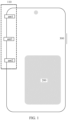
FIG. 1 is a schematic diagram of a wireless communication device according to an embodiment of this application; -
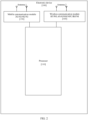
FIG. 2 is an architectural diagram of a wireless communication device according to an embodiment of this application; -
FIG. 3 is an architectural diagram of an antenna system according to an embodiment of this application; -
FIG. 4 is a schematic diagram of an antenna system according to an embodiment of this application; -
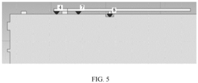
FIG. 5 is a structural diagram of another antenna system according to an embodiment of this application; -
FIG. 6a , corresponding toFIG. 5 , is an effect diagram in which a load of an input end of a second antenna is not adjusted; -
FIG. 6b is a schematic diagram of tuning of a radio frequency end of a second antenna according to an embodiment of this application; -
FIG. 6c , corresponding toFIG. 5 , is an effect diagram in which a load of an input end of a second antenna is adjusted; -
FIG. 7 is a schematic diagram of an S11 after different matching is debugged for a radio frequency end of a second antenna and a switch on an antenna side according to an embodiment of this application; -
FIG. 8 is a schematic diagram of another antenna system according to an embodiment of this application; -
FIG. 9 is a comparison diagram of an S11 of a first antenna when a second antenna is in different states as an auxiliary antenna according to an embodiment of this application; -
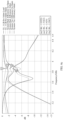
FIG. 10 is a comparison diagram of efficiency of a first antenna when a second antenna is in different states as an auxiliary antenna according to an embodiment of this application; -
FIG. 11 is a flowchart of a control method for an antenna system according to an embodiment of this application; -
FIG. 12 is a flowchart of another control method for an antenna system according to an embodiment of this application; and -
FIG. 13 is a flowchart of another control method for an antenna system according to an embodiment of this application. - To make a person skilled in the art more clearly understand solutions provided in this application, application scenarios of the technical solutions in this application are first introduced below.
- Embodiments of this application do not specifically limit an application scenario of a multiple-antenna system. In some possible embodiments, the multiple-antenna system is applicable to a wireless communication device, and the wireless communication device includes, but not limited to, a mobile phone, a tablet computer, a desktop computer, a laptop computer, a notebook computer, an ultra-mobile personal computer (Ultra-mobile Personal Computer, UMPC), a handheld computer, a netbook, a personal digital assistant (Personal Digital Assistant, PDA), a wearable mobile terminal, and a smart watch.
- For ease of understanding,
FIG. 1 is a schematic diagram of a mobile phone in which a multiple-antenna system is used. -
FIG. 1 is a schematic diagram of a wireless communication device according to an embodiment of this application. - As shown in
FIG. 1 , the mobile phone includes a multiple-antenna system 110, abattery 200, and aside button 300. In this embodiment, a description is made by using an example in which the antenna system includes three antennas. - The multiple-
antenna system 110 includes a first antenna ant1, a second antenna ant2, and a third antenna ant3 that are disposed at a location of a side frame of a wireless communication device (for example, a mobile phone). Thebattery 200 is configured to supply power to the mobile phone. Theside button 300 is configured for the mobile phone to receive an instruction from a user, for example, the user can long press theside button 300 to turn on or off the mobile phone and the like. - An internal architecture of the wireless communication device is described below with reference to the accompanying drawings.
-
FIG. 2 is an architectural diagram of a wireless communication device according to an embodiment of this application. - An
electronic device 100 may include aprocessor 110. Theprocessor 110 may include one or more processing units. For example, theprocessor 110 may include an application processor (application processor, AP), a modem processor, a graphics processing unit (graphics processing unit, GPU), an image signal processor (image signal processor, ISP), a controller, a video codec, a digital signal processor (digital signal processor, DSP), a baseband processor, and/or a neural-network processing unit (neural-network processing unit, NPU). Different processing units may be separate devices or may be integrated into one or more processors. - The controller may generate an operation control signal based on an instruction operation code and a timing signal, and read an instruction and control execution of the instruction.
- A memory may be further configured in the
processor 110, to store an instruction and data. In some embodiments, the memory in theprocessor 110 is a cache. The memory may store an instruction or data that has just been used or cyclically used by theprocessor 110. If theprocessor 110 needs to use the instruction or the data again, theprocessor 110 may directly invoke the instruction or the data from the memory, to avoid repeated access and reduce a waiting time of theprocessor 110, thereby improving system efficiency. - A wireless communication module 160 may provide a solution for wireless communication including a wireless local area network (wireless local area network, WLAN) (for example, a wireless fidelity (wireless fidelity, Wi-Fi) network), Bluetooth (Bluetooth, BT), and a global navigation satellite system (global navigation satellite system, GNSS), frequency modulation (frequency modulation, FM), a near field communication (near field communication, NFC) technology, an infrared (infrared, IR) technology, and the like to be applied to the
electronic device 100. The wireless communication module 160 may be one or more devices integrating at least one communication processing module. The wireless communication module 160 receives an electromagnetic wave by using anantenna 2, performs frequency modulation and filtering processing on an electromagnetic wave signal, and sends a processed signal to theprocessor 110. The wireless communication module 160 may alternatively receive a to-be-sent signal from theprocessor 110, perform frequency modulation and amplification on the to-be-sent signal, and convert the signal into an electromagnetic wave for radiation by using anantenna 2. - In some embodiments, in the
electronic device 100, anantenna 1 is coupled to amobile communication module 150, and theantenna 2 is coupled to the wireless communication module 160, so that theelectronic device 100 may communicate with a network and another device by using a wireless communication technology. The wireless communication technology may include a global system for mobile communications (global system for mobile communications, GSM), a general packet radio service (general packet radio service, GPRS), code division multiple access (code division multiple access, CDMA), wideband code division multiple access (wideband code division multiple access, WCDMA), time-division code division multiple access (time-division code division multiple access, TD-SCDMA), long term evolution (long term evolution, LTE), BT, GNSS, WLAN, NFC, FM, and/or IR technologies, and the like. The GNSS may include a global positioning system (global positioning system, GPS), a global navigation satellite system (global navigation satellite system, GLONASS), and a Beidou navigation satellite system (Beidou navigation satellite system, BDS), a quasi-zenith satellite system (quasi-zenith satellite system, QZSS) and/or a satellite based augmentation system (satellite based augmentation system, SBAS). - To improve performance of an antenna system disposed below a narrow bezel of a wireless communication device and enable an SAR to meet a requirement, the following describes an implementation of the antenna system provided in this application.
-
FIG. 3 is an architectural diagram of an antenna system according to an embodiment of this application. - This embodiment provides an antenna system, applicable to a wireless communication device, and including: a
radio frequency chip 301, a controller 304, and a plurality of antennas. Theradio frequency chip 301 is connected to the plurality of antennas by a power amplifier PA andswitches switch 302a, and the second antenna ANT2 is connected to the power amplifier PA by theswitch 302b. It should be understood that the plurality of antennas may correspond to a plurality of switches, and each antenna is connected to a corresponding switch. In addition, the plurality of antennas may share one power amplifier or the plurality of antennas may respectively correspond to different power amplifiers. This is not specifically limited in this embodiment of this application. - It should be understood that a quantity of auxiliary antennas is not limited in this embodiment of this application, for example, there may be one or two or more auxiliary antennas. An antenna may operate as the auxiliary antenna provided that the antenna does not operate and meets a condition for being the auxiliary antenna.
- The
controller 303 is configured to determine that a frequency band in which an antenna of the wireless communication device operates belongs to a preset to-be-improved frequency band of the first antenna ANT1, where the preset to-be-improved frequency band includes at least one frequency band. It should be understood that the preset to-be-improved frequency band may include one or more frequency bands, which specifically relates to a communication standard of the wireless communication device. - The controller is configured to determine whether the ith antenna operates; and set a load status of a radio frequency input end of the ith antenna and adjust a switch or Tuner state of the ith antenna when the ith antenna does not operate, so that the ith antenna becomes the auxiliary antenna of the first antenna ANT1, that is, synchronous tuning needs to be performed on the ith antenna, where the load status of the radio frequency input end is set to any one of the following: open (Open), broken, isolation (Isolation), or ground (GND).
- In the antenna system provided in this embodiment of this application, the controller first determines a frequency band in which an antenna of a wireless communication device currently operates, that is, needs to determine, for regardless of a single-card device or a dual-card device, whether a communication frequency is a frequency band included in a preset to-be-improved frequency band, and further determines whether an ith antenna operates if the frequency band in which the antenna currently operates belongs to the preset to-be-improved frequency band, and if the ith antenna does not operate, the ith antenna may be used as an auxiliary antenna, that is, the ith antenna is idle in the preset to-be-improved frequency band. Specifically, the controller can set a load status of the ith antenna to implement auxiliary work, where the load status may be adjusted as open, isolation, or ground. Conventionally, there is no technical solution in which the ith antenna is set to the auxiliary antenna. For example, when a first antenna operates, the remaining antennas do not perform any control. Because the ith antenna operates as the auxiliary antenna of the first antenna, that is, a radiator of the ith antenna may be used as a part of a radiator of the first antenna, a volume of the first antenna can be increased, and a bandwidth of the first antenna is increased. In addition, when the ith antenna is used as the auxiliary antenna of the first antenna, the ith antenna becomes a part of the first antenna, and there is no problem of isolation between the first antenna and the ith antenna.
-
FIG. 4 is a schematic diagram of an antenna system according to an embodiment of this application. - In this embodiment, a description is made by using an example in which the antenna system includes five antennas, that is, a first antenna Ant1, a second antenna Ant2, a third antenna Ant3, a fourth antenna Ant4, and a fifth antenna Ant5.
- In this embodiment, the first antenna Ant1 is a to-be-improved antenna, and the second antenna Ant2 is an auxiliary antenna. The second antenna Ant2 operates in other frequency bands, and the first antenna Ant1 and the second antenna Ant2 are connected to the
radio frequency chip 301 by aswitch 302 and a power amplifier PA-1. - When a
port 1 of theswitch 302 is connected to A, that is, when the first antenna Ant1 is connected to theradio frequency chip 301, a radio frequency path of the first antenna Ant1 is in a Load load operating state. - When a
port 4 of theswitch 302 is connected to B, that is, when the second antenna Ant2 is connected to theradio frequency chip 301, a radio frequency path of the second antenna Ant2 is in a Load load operating state. - When the second antenna Ant2 needs to be used as an auxiliary antenna of the first antenna Ant1, a port 2 (in an Open open state) or a port 3 (in a GND-short circuit state) of the
switch 302 may be controlled to connect to the port B, that is, theport 2 of theswitch 302 is in the open state, and theport 3 is in the short circuit state. That is, a load status of an input end of the second antenna Ant2 is open or ground. Certainly, the load status of the input end of the second antenna Ant2 may alternatively be controlled as isolation. Details are not described herein by using examples. If a path of the second antenna Ant2 further includes an antenna tuner such as a Switch or a Tuner, a matching status of the Switch or the Tuner of the second antenna Ant2 may be further synchronously adjusted, so that the second antenna Ant2 operates around an operating frequency band of the first antenna Ant1 that needs to be assisted. - A description is made below with reference to an antenna system of a mobile phone.
-
FIG. 5 is a structural diagram of another antenna system according to an embodiment of this application. - In this embodiment, a description is made by using an example of joint tuning of LB and n78 integrated dual-antenna radio frequency path.
- As shown in
FIG. 5 , apin 4 represents a first antenna, and the first antenna operates in a frequency band N78. Apin 7 represents a second antenna, and apin 8 is connected to a switch. Thepin 4 is a feed, thepin 7 is a low-frequency feedpoint, and a status of thepin 7 may be adjusted as open (Open) and a load (Load) state. For example, after it is recognized that a mobile phone is a single card or in a non-ENDC LB+N78 state, a radio frequency input end (that is, the pin 4) in an LB is switched to Open, and performance (a bandwidth and efficiency) in the N78 is improved by using a Switch of the LB antenna, that is, the second antenna is adjusted to be near a frequency of the first antenna. - To better describe the beneficial effect of the technical solution provided in this embodiment of this application, a difference of the antenna system before and after the second antenna is adjusted as the auxiliary antenna is described below by comparison.
-
FIG. 6a , corresponding toFIG. 5 , is an effect diagram in which a load of an input end of a second antenna is not adjusted. - The following describes an S11 and an S21 that are between an LB radio frequency end of a second auxiliary antenna and a first antenna in operation (that is, in a load state).
- In a case that the LB is in the load state, a match (Match) of a switch on a low frequency side of the second antenna is tuned, a parasitic resonance can be formed between N78 and 3.8 GHz in a case of 0 om, and a bandwidth is increased. However, in this case, an isolation S21 between the first antenna and the second antenna is less than -10 dB, which does not meet a requirement.
- Therefore, to enable the S21 to meet the requirement, the following describes an implementation provided in this embodiment of this application.
-
FIG. 6b is a schematic diagram of tuning of a radio frequency end of a second antenna according to an embodiment of this application. - According to the technical solution provided in this embodiment, a Low Band antenna input end (a port 2) of the second antenna is adjusted as open, that is, Open (a load shown in the figure), and Matching (a port 8) of a Switch on a switch side of a tuned N78 integrated Low Band end is adjusted as ground. As shown in the figure, the
pin 8 is grounded, so that a load status of an input end of the second antenna is changed, and the second antenna becomes the auxiliary antenna of the first antenna. Matching of an N78 source input end of the first antenna is not changed. -
FIG. 6c , corresponding toFIG. 5 , is an effect diagram in which a load of an input end of a second antenna is adjusted. - In a case that an input end of a Low Band second antenna is Open, both a bandwidth and efficiency of an N78 antenna are better than that of the Low Band antenna in a load state, and efficiency of the antenna system is improved by about 1 dB, and there is no problem of isolation between the first antenna and the second antenna.
- In a case that the input end of the Low Band second antenna is Open, an antenna switch on an LB side may be further adjusted to switch different Matching (an inductance, a capacitance, 0 ohm), and an auxiliary parasitic is adjusted at different resonance positions, so that the bandwidth of the first antenna in the N78 frequency band is widened.
-
FIG. 7 is a schematic diagram of an S11 after different matching is debugged for a radio frequency end of a second antenna and a switch on an antenna side according to an embodiment of this application. - It can be seen from
FIG. 7 that an antenna switch on an LB side is directly grounded, and a resonance position is different from a resonance position when the antenna switch is grounded through inductors of different inductances, so that, different bandwidths can be adjusted, that is, different bandwidths are widened. - The implementation of the antenna system is described above, and the following describes an implementation of another antenna system.
- A description is made by using an example in which a first antenna operates in a frequency band whose performance needs to be improved in a middle/high frequency band MHB (1.71 GHz to 2.7 GHz in 2G/3G/4G/5G), that is, a preset to-be-improved frequency band is (B1/B3/B7/B41 in an LTE communication standard and n1/n3/n7/n41 in an NR communication standard) in the MHB, and a second antenna (an auxiliary antenna) operates in a non-MHB frequency band.
Communication standard MHB-Band (middle/high frequency band-1.71 to 2.7 GHz) Band (frequency band) that needs to be improved for the antenna 2G GSM B2/ B3 \ 3G WCDMA B1 \ 4G LTE B1/B2/B3/B7/B34/B39/B41 B1/B3/B7/ B41 5G NR n1/n3/n7/n41 n1/n3/n7/n41 - For example, for a single-
card 4G mobile phone, if a frequency band in which an antenna of the mobile phone operates is a B5, because the B5 does not belong to a to-be-improved frequency band, the single-card mobile phone operating in the B5 frequency band does not need to be adjusted, that is, an auxiliary antenna does not need to be set for the first antenna in operation. It should be understood that as shown in the table, if an antenna operates in aB 1, a B3, or a B7, no auxiliary antenna needs to be set, and the frequency bands are not included in the to-be-improved frequency band. -
FIG. 8 is a schematic diagram of another antenna system according to an embodiment of this application. - A
pin 3 corresponds to an MHB feed, that is, a feedpoint, of a first antenna. Apin 2 corresponds to a feedpoint of a second antenna, apin 1 is a switch tuning point, and a switch is connected to thepin 2 in parallel. Thepin 2 may be adjusted as Open or Load. When the second antenna is used as an auxiliary antenna of the first antenna, thepin 2 may be adjusted to the Open state. - For example, after it is recognized that a mobile phone is in a single card MHB and non-ENDC (EUTRA NR Dual-Connectivity)/CA (Carrier Aggregation) first antenna and second antenna combined operating state, a radio frequency input end of the second antenna is set to Open, and MHB performance (a bandwidth and efficiency) is improved by tuning a Match of an antenna Switch, and an SAR is reduced. ENDC is one of 4G-LTE and 5G-NR dual connectivity operating mode and a 5G operating model. CA is a carrier aggregation technology, which means multi-frequency band dual connectivity operation.
- When the second antenna is in a non-Load state, a load of an input end is tuned to open (Open), and the second antenna is used as an auxiliary antenna of the first antenna by tuning a switch and Matching of the second antenna, so that a bandwidth of an antenna in an original middle/high frequency band MHB can be widened, and a B7 frequency band can be covered. In addition, there is no problem of isolation between the second antenna and the first antenna, that is, the isolation meets the requirement.
-
FIG. 9 is a comparison diagram of an S11 of a first antenna when a second antenna is in different states as an auxiliary antenna according to an embodiment of this application. - Three different curves are shown in
FIG. 9 , which are respectively an S11 when a radio frequency input end of the second antenna is adjusted into different states. - S11_Open (4 in the curve is a resonance position in the curve): an S11 of the first antenna when the radio frequency input end of the second antenna is set to Open and a switch is not tuned.
- S11_GND (3 in the curve is a resonance position in the curve): an S11 of the first antenna when the radio frequency input end of the second antenna is set to GND and the switch is not tuned.
- S11_B7 Para (both 1 and 2 in the curve are resonance positions in the curve): an S11 of the first antenna when the radio frequency input end of the second antenna is set to Open and the switch is tuned. It can be obviously seen that a bandwidth of the first antenna is widened, and there is an additional resonance, that is, 1 and 2 respectively represent two different resonance positions.
-
FIG. 10 is a comparison diagram of efficiency of a first antenna when a second antenna is in different states as an auxiliary antenna according to an embodiment of this application. - When the second antenna is in a non-Load state, the radio frequency input end is tuned to Open, and a switch and Matching of the second antenna are tuned, so that the second antenna is used as a parasitic auxiliary antenna, an original S11 bandwidth of the first antenna in the MHB can be widened, and antenna efficiency of the first antenna in the B7 frequency band can be improved by about 2 dB to 4 dB compared with original antenna efficiency.
- According to the technical solution provided in this embodiment of this application, in addition to improving the S11 and the antenna efficiency, the B7 frequency band is at the top of the mobile phone, that is, an SAR on a Top surface is also reduced by about 45% compared with an original SAR. For specific data, refer to the following table.
24 dBm Tot. Efficiency Body Top 5 mm-(normalization TRP 19 dBm) Para-B7 Open Gnd Para-B7 Open Gnd B3-1747 MHz -0.64 -0.64 -0.64 0.57 0.57 0.57 B1-1950 MHz -3.0 -2.92 -2.98 1.42 1.43 1.43 B7-2535 MHz -2.6 -4.14 -3.92 0.50 0.90 0.99 - According to the antenna system provided in the embodiments of this application, when an auxiliary antenna is selected for a first antenna in operation, it is first determined whether a frequency band in which a wireless communication device is operating belongs to a preset to-be-improved frequency band, if the frequency band belongs to the preset to-be-improved frequency band, it is determined whether an ith antenna operates in the preset to-be-improved frequency band, if the ith antenna operates in the preset to-be-improved frequency band, the ith antenna cannot be used as the auxiliary antenna, and if the ith antenna does not operate in the preset to-be-improved frequency band, the ith antenna can be used as the auxiliary antenna.
- A working principle of selecting an auxiliary antenna is described below from perspectives of a single-card wireless communication device and a dual-card wireless communication device.
- First, a single card is described, that is, when the wireless communication device includes the single card, in the antenna system provided in the embodiments of this application, a specific implementation in which the controller determines the frequency band in which the antenna of the wireless communication device operates belongs to the preset to-be-improved frequency band includes: determining that the single card performs communication in a single frequency band; and determining that the single frequency band of the single card of the wireless communication device is one of the preset to-be-improved frequency band. The preset to-be-improved frequency band may include one or more frequency bands.
- When the wireless communication device includes the single card, a specific implementation in which the controller determines that the frequency band in which the antenna of the wireless communication device operates belongs to the preset to-be-improved frequency band includes: determining that the single card performs communication in a CA frequency band or an ENDC frequency band, and determining that the ith antenna does not operate in the CA frequency band or the ENDC frequency band; and determining that the CA frequency band or the ENDC frequency band of the single card belongs to the preset to-be-improved frequency band.
- The following describes a dual card. When the wireless communication device includes the dual card, in the antenna system provided in the embodiments of this application, a specific implementation in which the controller determines the frequency band in which the antenna of the wireless communication device operates belongs to the preset to-be-improved frequency band includes: determining, when the dual card is dual receive dual SIM dual standby, that both a primary card and a secondary card of the dual card perform communication in single frequency bands; and determining that both the single frequency band of the primary card and the single frequency band of the secondary card belong to the preset to-be-improved frequency band. If the single frequency band in which one card of the dual card operates does not belong to the preset to-be-improved frequency band, the auxiliary antenna is not selected for the first antenna.
- When the wireless communication device includes the dual card, in the antenna system provided in the embodiments, the controller is further configured to determine a MIMO operating state in a current operating frequency band to determine whether ith antenna operates, and set the load status of the radio frequency input end of the ith antenna and adjust the switch or Tuner state on the ith antenna side when the ith antenna does not operate, so that the ith antenna is used as the auxiliary antenna of the first antenna. It should be understood that if the ith antenna operates in 4*4MIMO, the ith antenna cannot be used as the auxiliary antenna. The ith antenna can be used as the auxiliary antenna when operating in 2∗2MIMO, that is, when the ith antenna operates in 2∗2MIMO, two antennas do not operate and are in an idle state, so that the ith antenna can be used as the auxiliary antenna.
- According to the antenna system provided in the embodiments of this application, an auxiliary antenna can be adjusted for both a single-card wireless communication device and a dual-card wireless communication device, and the auxiliary antenna can be configured for a first antenna in operation, so that the auxiliary antenna becomes a part of the first antenna, and a bandwidth of the first antenna is widened. Because the auxiliary antenna does not operate in another frequency band, there is no problem of isolation between the auxiliary antenna and the first antenna, and the isolation between the two antennas meets the requirement.
- In addition, the technical solution provided in the embodiments of this application can not only used for improving antenna performance in cellular communication, but also used for improving performance of a required cellular antenna by determining whether antennas such as GPS and Wi-Fi/BT antennas in the remaining communication standards operate, adjusting a load status of a radio frequency input end of the GPS or Wi-Fi antenna and using the GPS or Wi-Fi antenna as auxiliary of the cellular antenna.
- Based on the antenna system provided in the foregoing embodiments, an embodiment of this application further provides a control method for an antenna system. A detailed description is made below with reference to the accompanying drawings.
-
FIG. 11 is a flowchart of a control method for an antenna system according to an embodiment of this application. - The control method for an antenna system provided in this embodiment is applicable to an antenna system of a wireless communication device, where the antenna system includes: a radio frequency chip, a controller, and a plurality of antennas. The radio frequency chip is connected to the plurality of antennas by a power amplifier and switches. The plurality of antennas include: a first antenna, a second antenna, ..., and an Nth antenna, where N is an integer greater than or equal to 2. The first antenna is a to-be-improved antenna, an ith antenna is an auxiliary antenna, and i is any one of 2 to N.
- The method includes the following steps.
- S1101: Determine that a frequency band in which an antenna of the wireless communication device operates belongs to a preset to-be-improved frequency band of the first antenna, where the preset to-be-improved frequency band includes at least one frequency band.
- S1102: Determine whether the ith antenna operates.
- S1103: Set a load status of a radio frequency input end of the ith antenna and adjust a switch or Tuner state on the ith antenna side when the ith antenna does not operate, so that the ith antenna becomes the auxiliary antenna of the first antenna, where the load status of the radio frequency input end is set to any one of the following: open (Open), broken, isolation (Isolation), or ground (GND).
- According to the control method for an antenna system provided in this embodiment of this application, a frequency band in which an antenna of a wireless communication device currently operates is first determined, that is, whether a communication frequency is a frequency band included in a preset to-be-improved frequency band needs to be determined for regardless of a single-card device or a dual-card device, and whether an ith antenna operates is further determined if the frequency band in which the antenna currently operates belongs to the preset to-be-improved frequency band, and if the ith antenna does not operate, the ith antenna may be used as an auxiliary antenna, that is, the ith antenna is idle in the preset to-be-improved frequency band. Specifically, the controller can set a load status of the ith antenna to implement auxiliary work, where the load status may be adjusted as open, isolation, or ground. Conventionally, there is no technical solution in which the ith antenna is set to the auxiliary antenna. For example, when a first antenna operates, the remaining antennas do not perform any control. Because the ith antenna operates as the auxiliary antenna of the first antenna, that is, a radiator of the ith antenna may be used as a part of a radiator of the first antenna, a volume of the first antenna can be increased, and a bandwidth of the first antenna is increased. In addition, when the ith antenna is used as the auxiliary antenna of the first antenna, the ith antenna becomes a part of the first antenna, and there is no problem of isolation between the first antenna and the ith antenna.
- An implementation method in which a wireless communication device includes a single card is described in detail below.
-
FIG. 12 is a flowchart of another control method for an antenna system according to an embodiment of this application. - S1201: Obtain information about a wireless communication device, where the information includes a communication standard (2G to 5G), and if the communication standard is 4G, CA combined frequency band information is obtained; and if the communication standard is 5G, 5G non-standalone (NSA, Non-Standalone) networking-ENDC combined frequency band information is obtained. In a case of a single frequency band, specific frequency band information is obtained.
- S1202: Determine whether the single frequency band is a frequency band of a preset to-be-improved frequency band. If the single frequency band is the frequency band of the preset to-be-improved frequency band, step S1204 is performed; and if the single frequency band is not the frequency band of the preset to-be-improved frequency band, step S1205 is performed.
- S1203: Determine, when a first antenna operates in a CA combined frequency band or an ENDC combined frequency band, whether an ith antenna operates in the combined frequency band. If the ith antenna does not operate in the combined frequency band, step S1204 is performed; and if the ith antenna operates in the combined frequency band, step S1205 is performed.
- S1204: Set a load status of a radio frequency input end of the ith antenna and adjust a switch or Tuner state on the ith antenna side, so that the ith antenna becomes an auxiliary antenna of the first antenna, where the load status of the radio frequency input end is set to any one of the following: open, isolation, or ground.
- S1205: Skip changing a logic state of the radio frequency input end of the ith antenna, that is, skip performing any adjustment on the ith antenna.
- An implementation in which a wireless communication device includes a dual card is described in detail below.
-
FIG. 13 is a flowchart of another control method for an antenna system according to an embodiment of this application. - S1301: Determine, when a wireless communication device includes a dual card, whether the dual card is dual SIM dual active (DSDA, Dual Sim Dual Active) or dual receive dual SIM dual standby (DR-DSDS, Dual Receive Dual SIM Dual Standby).
- S1302: Obtain communication information of each card when the dual card is the DR-DSDS, where the communication information includes communication standards (2G to 5G), and if the communication standard is 4G, CA combined frequency band information is obtained; and if the communication standard is 5G, NSA-ENDC combined frequency band information is obtained. In a case of a single frequency band, specific frequency band information is obtained.
- S1303: When each card, that is, a primary card and a secondary card, is in a single frequency band, the single frequency band in which each card operates belongs to a to-be-improved frequency band of a first antenna. That is, it is determined whether frequency bands in which the primary card and the secondary card operate are the to-be-improved frequency band of the first antenna.
- S1304: Determine whether an ith antenna operates, where if the ith antenna does not operate, step S1305 is performed; and if the ith antenna operates, S1306 is performed. That is, if the ith antenna does not operate, the ith antenna can be used as an auxiliary antenna of the first antenna. If the ith antenna operates, the ith antenna cannot be used as the auxiliary antenna.
- S1305: Set a load status of a radio frequency input end of the ith antenna and adjust a switch or Tuner state on the ith antenna side, so that the ith antenna becomes an auxiliary antenna of the first antenna, where the load status of the radio frequency input end is set to any one of the following: open, isolation, or ground.
- S1306: Skip changing a logic state of the radio frequency input end of the ith antenna, that is, skip performing any adjustment on the ith antenna.
- When the wireless communication device includes a single card, the determining that a frequency band in which an antenna of the wireless communication device operates belongs to a preset to-be-improved frequency band specifically includes:
- determining that the single card performs communication in a single frequency band; and
- determining that the single frequency band of the single card of the wireless communication device is one of the preset to-be-improved frequency band.
- When the wireless communication device includes a single card, the determining that a frequency band in which an antenna of the wireless communication device operates belongs to a preset to-be-improved frequency band specifically includes:
- determining that the single card performs communication in a CA frequency band or an ENDC frequency band, and determining that the ith antenna does not operate in the CA frequency band or the ENDC frequency band; and
- determining that the CA frequency band or the ENDC frequency band of the single card belongs to the preset to-be-improved frequency band.
- When the wireless communication device includes a dual card, the determining that a frequency band in which an antenna of the wireless communication device operates belongs to a preset to-be-improved frequency band specifically includes:
- determining, when the dual card is dual receive dual SIM dual standby, that both a primary card and a secondary card of the dual card perform communication in single frequency bands; and
- determining that both the single frequency band of the primary card and the single frequency band of the secondary card belong to the preset to-be-improved frequency band.
- According to the control method for an antenna system provided in the embodiments of this application, the determining whether the ith antenna operates specifically includes: determining a MIMO operating state in a current operating frequency band to determine whether the ith antenna operates, and setting the load status of the radio frequency input end of the ith antenna and adjusting the switch or Tuner state on the ith antenna side when the ith antenna does not operate.
- Based on the antenna system and the control method provided in the foregoing embodiments, an embodiment of this application further provides a wireless communication device. A detailed description is made below.
- The wireless communication device provided in this embodiment of this application includes: the antenna system described in the foregoing embodiments and further includes: a SIM card, where the SIM card is a single card or a dual card; and
the SIM card sends and receives signals through the antenna system during communication. - A specific form of the wireless communication device is not specifically limited in the embodiments of this application, for example, may be a communication terminal such as a mobile phone. Because the wireless communication device includes the antenna system described in the foregoing embodiments, the antenna system includes a plurality of antennas. When a first antenna operates, an ith antenna meeting a requirement may be found from the remaining antennas, a load of a radio frequency input end of the ith antenna is set, and then the ith antenna is adjusted as an auxiliary antenna of the first antenna, so that the ith antenna can assist the first antenna in operating and become a parasitic antenna of the first antenna or a part of the first antenna, that is, a volume of the first antenna can be expanded, to improve a bandwidth of the first antenna. Because the ith antenna is the part of the first antenna, there is no problem of isolation between the ith antenna and the first antenna.
- It should be understood that, in this application, "at least one" means one or more, and "a plurality of" means two or more. The term "and/or" describes an association between associated objects and represents that three associations may exist. For example, "A and/or B" may indicate that only A exists, only B exists, and both A and B exist, wherein A and B may be singular or plural. The character "/" in this specification generally indicates an "or" relationship between the associated objects. "At least one of the following" or a similar expression thereof refers to any combination of these items, including one item or any combination of more items. For example, at least one of a, b, or c may indicate: a, b, c, "a and b", "a and c", "b and c", or "a, b, and c", where a, b, and c may be singular or plural.
- The foregoing embodiments are merely intended for describing the technical solutions of this application, but not for limiting this application. It should be understood by a person of ordinary skill in the art that although this application has been described in detail with reference to the foregoing embodiments, modifications can be made to the technical solutions described in the foregoing embodiments, or equivalent replacements can be made to some technical features in the technical solutions, and these modifications or replacements will not cause the essence of corresponding technical solutions to depart from the spirit and scope of the technical solutions in the embodiments of this application.
Claims (11)
- An antenna system, applicable to a wireless communication device, and comprising: a radio frequency chip, a controller, and a plurality of antennas, wherein the radio frequency chip is connected to the plurality of antennas by a power amplifier and switches; the plurality of antennas comprise: a first antenna, a second antenna, ..., and an Nth antenna, wherein N is an integer greater than or equal to 2; and the first antenna is a to-be-improved antenna, an ith antenna is an auxiliary antenna, and i is any one of 2 to N; andthe controller is configured to determine that a frequency band in which an antenna of the wireless communication device operates belongs to a preset to-be-improved frequency band of the first antenna, wherein the preset to-be-improved frequency band comprises at least one frequency band;determine whether the ith antenna operates; and set a load status of a radio frequency input end of the ith antenna and adjust a switch or Tuner state on the ith antenna side when the ith antenna does not operate, so that the ith antenna becomes the auxiliary antenna of the first antenna, wherein the load status of the radio frequency input end is set to any one of the following: open, broken, isolation, or ground.
- The system according to claim 1, wherein when the wireless communication device comprises a single card, that the controller is specifically configured to determine that the frequency band in which the antenna of the wireless communication device operates belongs to the preset to-be-improved frequency band specifically comprises:determining that the single card performs communication in a single frequency band; anddetermining that the single frequency band of the single card of the wireless communication device is one of the preset to-be-improved frequency band.
- The system according to claim 1, wherein when the wireless communication device comprises a single card, that the controller is specifically configured to determine that the frequency band in which the antenna of the wireless communication device operates belongs to the preset to-be-improved frequency band specifically comprises:determining that the single card performs communication in a CA frequency band or an ENDC frequency band, and determining that the ith antenna does not operate in the CA frequency band or the ENDC frequency band; anddetermining that the CA frequency band or the ENDC frequency band of the single card belongs to the preset to-be-improved frequency band.
- The system according to claim 1, wherein when the wireless communication device comprises a dual card, that the controller is specifically configured to determine that the frequency band in which the antenna of the wireless communication device operates belongs to the preset to-be-improved frequency band specifically comprises:determining, when the dual card is dual receive dual SIM dual standby, that both a primary card and a secondary card of the dual card perform communication in single frequency bands; anddetermining that both the single frequency band of the primary card and the single frequency band of the secondary card belong to the preset to-be-improved frequency band.
- The system according to claim 1, wherein the controller is further configured to determine a MIMO operating state in a current operating frequency band to determine whether the ith antenna operates, and set the load status of the radio frequency input end of the ith antenna and adjust the switch or Tuner state on the ith antenna side when the ith antenna does not operate.
- A control method for an antenna system, applicable to an antenna system of a wireless communication device, wherein the antenna system comprises: a radio frequency chip, a controller, and a plurality of antennas; the radio frequency chip is connected to the plurality of antennas by a power amplifier and switches; the plurality of antennas comprise: a first antenna, a second antenna, ..., and an Nth antenna, wherein N is an integer greater than or equal to 2; and the first antenna is a to-be-improved antenna, an ith antenna is an auxiliary antenna, and i is any one of 2 to N; and
the method comprises:determining that a frequency band in which an antenna of the wireless communication device operates belongs to a preset to-be-improved frequency band of the first antenna, wherein the preset to-be-improved frequency band comprises at least one frequency band;determining whether the ith antenna operates; andsetting a load status of a radio frequency input end of the ith antenna and adjusting a switch or Tuner state on the ith antenna side when the ith antenna does not operate, so that the ith antenna becomes the auxiliary antenna of the first antenna, wherein the load status of the radio frequency input end is set to any one of the following: open, isolation, or ground. - The method according to claim 1, wherein when the wireless communication device comprises a single card, the determining that a frequency band in which an antenna of the wireless communication device operates belongs to a preset to-be-improved frequency band specifically comprises:determining that the single card performs communication in a single frequency band; anddetermining that the single frequency band of the single card of the wireless communication device is one of the preset to-be-improved frequency band.
- The method according to claim 1, wherein when the wireless communication device comprises a single card, the determining that a frequency band in which an antenna of the wireless communication device operates belongs to a preset to-be-improved frequency band specifically comprises:determining that the single card performs communication in a CA frequency band or an ENDC frequency band, and determining that the ith antenna does not operate in the CA frequency band or the ENDC frequency band; anddetermining that the CA frequency band or the ENDC frequency band of the single card belongs to the preset to-be-improved frequency band.
- The method according to claim 1, wherein when the wireless communication device comprises a dual card, the determining that a frequency band in which an antenna of the wireless communication device operates belongs to a preset to-be-improved frequency band specifically comprises:determining, when the dual card is dual receive dual SIM dual standby, that both a primary card and a secondary card of the dual card perform communication in single frequency bands; anddetermining that both the single frequency band of the primary card and the single frequency band of the secondary card belong to the preset to-be-improved frequency band.
- The method according to claim 6, wherein the determining whether the ith antenna operates specifically comprises: determining a MIMO operating state in a current operating frequency band to determine whether the ith antenna operates, and setting the load status of the radio frequency input end of the ith antenna and adjusting the switch or Tuner state on the ith antenna side when the ith antenna does not operate.
- A wireless communication device, comprising the antenna system according to any of claims 1 to 5 and further comprising: a SIM card, wherein the SIM card is a single card or a dual card; and
the SIM card sends and receives signals through the antenna system during communication.
Applications Claiming Priority (2)
| Application Number | Priority Date | Filing Date | Title |
|---|---|---|---|
| CN202210240268.7A CN115064882B (en) | 2022-03-10 | 2022-03-10 | Antenna system, method and wireless communication device |
| PCT/CN2022/140644 WO2023169044A1 (en) | 2022-03-10 | 2022-12-21 | Antenna system, method, and wireless communication device |
Publications (3)
| Publication Number | Publication Date |
|---|---|
| EP4270657A1 true EP4270657A1 (en) | 2023-11-01 |
| EP4270657A4 EP4270657A4 (en) | 2024-07-24 |
| EP4270657B1 EP4270657B1 (en) | 2025-08-20 |
Family
ID=83197403
Family Applications (1)
| Application Number | Title | Priority Date | Filing Date |
|---|---|---|---|
| EP22879566.2A Active EP4270657B1 (en) | 2022-03-10 | 2022-12-21 | Antenna system, method, and wireless communication device |
Country Status (4)
| Country | Link |
|---|---|
| US (1) | US12519253B2 (en) |
| EP (1) | EP4270657B1 (en) |
| CN (2) | CN117374613A (en) |
| WO (1) | WO2023169044A1 (en) |
Families Citing this family (3)
| Publication number | Priority date | Publication date | Assignee | Title |
|---|---|---|---|---|
| CN117374613A (en) | 2022-03-10 | 2024-01-09 | 荣耀终端有限公司 | Wireless communication equipment and control method of wireless communication equipment |
| CN116345147B (en) * | 2023-02-16 | 2023-11-21 | 荣耀终端有限公司 | Antenna tuning method and terminal equipment |
| CN119696614A (en) * | 2023-09-18 | 2025-03-25 | 荣耀终端股份有限公司 | Antenna state control method, chip, electronic device and readable storage medium |
Family Cites Families (22)
| Publication number | Priority date | Publication date | Assignee | Title |
|---|---|---|---|---|
| JP2006186961A (en) * | 2004-12-02 | 2006-07-13 | Casio Comput Co Ltd | Receiving device, receiving circuit, and receiving method |
| US8106838B2 (en) * | 2009-02-05 | 2012-01-31 | Research In Motion Limited | Mobile wireless communications device having diversity antenna system and related methods |
| GB0914926D0 (en) | 2009-08-26 | 2009-09-30 | Secr Defence | Hybrid RF reflection measurement system (HRS) |
| US8942644B2 (en) * | 2011-11-11 | 2015-01-27 | Apple Inc. | Systems and methods for protecting microelectromechanical systems switches from radio-frequency signals using switching circuitry |
| CN103887595B (en) | 2012-12-21 | 2016-08-17 | 宏达国际电子股份有限公司 | Antenna system |
| US9667279B2 (en) * | 2013-12-20 | 2017-05-30 | Google Technology Holdings LLC | Systems and methods for a universal antenna module |
| WO2015143640A1 (en) * | 2014-03-26 | 2015-10-01 | 华为终端有限公司 | Radio frequency front-end system, signal transmission control method and mobile terminal |
| US9602156B2 (en) * | 2014-04-22 | 2017-03-21 | Skyworks Solutions, Inc. | Apparatus and methods for diversity modules |
| CN105656508A (en) | 2014-11-13 | 2016-06-08 | 中兴通讯股份有限公司 | Antenna switching control method and terminal |
| GB2533339A (en) * | 2014-12-17 | 2016-06-22 | Vertu Corp Ltd | Multiband slot antenna system and apparatus |
| US9979080B2 (en) * | 2015-07-29 | 2018-05-22 | Qualcomm Incorporated | Calibration and adaptive control of antenna tuners |
| US9634697B2 (en) * | 2015-09-09 | 2017-04-25 | Qualcomm Incorporated | Antenna selection and tuning |
| US10937019B2 (en) | 2016-06-08 | 2021-03-02 | Square, Inc. | Wireless communication system with auxiliary antenna |
| CN106252845A (en) * | 2016-07-22 | 2016-12-21 | 宇龙计算机通信科技(深圳)有限公司 | A kind of antenna, carrier radio frequency circuit, terminal and carrier polymerizing method |
| WO2018053746A1 (en) * | 2016-09-22 | 2018-03-29 | Qualcomm Incorporated | Techniques and apparatuses for opportunistically operating a dual receive, dual sim dual standby (dr-dsds) device as a dual sim, dual active (dsda) device |
| CN110289885B (en) * | 2019-07-02 | 2021-03-02 | 维沃移动通信有限公司 | A kind of antenna tuning method and terminal |
| CN111800159B (en) * | 2020-06-30 | 2021-12-24 | 联想(北京)有限公司 | Control method and electronic equipment |
| CN114069228B (en) * | 2020-08-07 | 2023-08-22 | 华为技术有限公司 | Antenna power supply system and electronic equipment |
| CN113131226B (en) * | 2021-04-20 | 2025-08-12 | 努比亚技术有限公司 | Multi-input multi-output antenna system, antenna control method and mobile terminal |
| CN215771542U (en) * | 2021-05-28 | 2022-02-08 | 荣耀终端有限公司 | Three-mode broadband terminal antenna and terminal equipment |
| CN113612498B (en) * | 2021-09-30 | 2021-12-31 | 荣耀终端有限公司 | Antenna configuration method and device |
| CN117374613A (en) * | 2022-03-10 | 2024-01-09 | 荣耀终端有限公司 | Wireless communication equipment and control method of wireless communication equipment |
-
2022
- 2022-03-10 CN CN202311128539.0A patent/CN117374613A/en active Pending
- 2022-03-10 CN CN202210240268.7A patent/CN115064882B/en active Active
- 2022-12-21 US US18/032,053 patent/US12519253B2/en active Active
- 2022-12-21 EP EP22879566.2A patent/EP4270657B1/en active Active
- 2022-12-21 WO PCT/CN2022/140644 patent/WO2023169044A1/en not_active Ceased
Also Published As
| Publication number | Publication date |
|---|---|
| US20240372273A1 (en) | 2024-11-07 |
| CN115064882B (en) | 2023-09-08 |
| EP4270657B1 (en) | 2025-08-20 |
| WO2023169044A1 (en) | 2023-09-14 |
| CN115064882A (en) | 2022-09-16 |
| CN117374613A (en) | 2024-01-09 |
| US12519253B2 (en) | 2026-01-06 |
| EP4270657A4 (en) | 2024-07-24 |
Similar Documents
| Publication | Publication Date | Title |
|---|---|---|
| EP4270657B1 (en) | Antenna system, method, and wireless communication device | |
| CN113659995B (en) | Radio frequency system and communication device | |
| EP2720378B1 (en) | Antenna module comprising dual swapping switches for meeting the demands of linearity in carrier aggregation systems | |
| EP4254808A1 (en) | Radio frequency l-pa mid device, radio frequency transceiving system and communication device | |
| CN113676206B (en) | Radio frequency system and communication device | |
| US9142879B2 (en) | Wireless electronic devices with a metal perimeter including a plurality of antennas | |
| CN114759943B (en) | Radio frequency front end module, and method and device for controlling radio frequency front end module | |
| EP4287516A1 (en) | Radio frequency pa mid device, radio frequency system and communication device | |
| US20120003944A1 (en) | Radio transceiver for mobile communication terminal | |
| US9825352B2 (en) | Wireless electronic devices including a feed structure connected to a plurality of antennas | |
| EP4243200A1 (en) | Antenna system, wireless communication system, and electronic device | |
| CN216721327U (en) | RF Front End Modules and RF Systems | |
| US20240154295A1 (en) | Antenna and communication device | |
| CN216057092U (en) | Electronic equipment | |
| US20160127006A1 (en) | Arbitrator for Multi-Radio Antenna Switching | |
| CN216721326U (en) | RF Front End Modules and RF Systems | |
| US9484978B2 (en) | System and method for communication with adjustable signal phase and power | |
| Wang | Overview of future antenna design for mobile terminals | |
| CN215871405U (en) | Radio frequency system and communication device | |
| CN215871375U (en) | RF transmitter modules, RF systems and communication equipment | |
| CN100428643C (en) | antenna module | |
| Fang et al. | Design of a multi-mode integrated MIMO antenna for broadband mobile communications with low SAR | |
| CN216721329U (en) | Radio frequency module and communication equipment | |
| Yu et al. | A Compact Multi Antenna Design with High Isolation in 5G Full Screen Mobile Phone | |
| Lai | Design of Multi Band RF Frontend Integration |
Legal Events
| Date | Code | Title | Description |
|---|---|---|---|
| STAA | Information on the status of an ep patent application or granted ep patent |
Free format text: STATUS: UNKNOWN |
|
| STAA | Information on the status of an ep patent application or granted ep patent |
Free format text: STATUS: THE INTERNATIONAL PUBLICATION HAS BEEN MADE |
|
| PUAI | Public reference made under article 153(3) epc to a published international application that has entered the european phase |
Free format text: ORIGINAL CODE: 0009012 |
|
| STAA | Information on the status of an ep patent application or granted ep patent |
Free format text: STATUS: REQUEST FOR EXAMINATION WAS MADE |
|
| 17P | Request for examination filed |
Effective date: 20230418 |
|
| AK | Designated contracting states |
Kind code of ref document: A1 Designated state(s): AL AT BE BG CH CY CZ DE DK EE ES FI FR GB GR HR HU IE IS IT LI LT LU LV MC ME MK MT NL NO PL PT RO RS SE SI SK SM TR |
|
| A4 | Supplementary search report drawn up and despatched |
Effective date: 20240620 |
|
| RIC1 | Information provided on ipc code assigned before grant |
Ipc: H04B 1/3827 20150101ALI20240614BHEP Ipc: H01Q 1/22 20060101ALI20240614BHEP Ipc: H01Q 21/00 20060101AFI20240614BHEP |
|
| GRAP | Despatch of communication of intention to grant a patent |
Free format text: ORIGINAL CODE: EPIDOSNIGR1 |
|
| STAA | Information on the status of an ep patent application or granted ep patent |
Free format text: STATUS: GRANT OF PATENT IS INTENDED |
|
| DAV | Request for validation of the european patent (deleted) | ||
| DAX | Request for extension of the european patent (deleted) | ||
| INTG | Intention to grant announced |
Effective date: 20250312 |
|
| GRAS | Grant fee paid |
Free format text: ORIGINAL CODE: EPIDOSNIGR3 |
|
| GRAA | (expected) grant |
Free format text: ORIGINAL CODE: 0009210 |
|
| STAA | Information on the status of an ep patent application or granted ep patent |
Free format text: STATUS: THE PATENT HAS BEEN GRANTED |
|
| AK | Designated contracting states |
Kind code of ref document: B1 Designated state(s): AL AT BE BG CH CY CZ DE DK EE ES FI FR GB GR HR HU IE IS IT LI LT LU LV MC ME MK MT NL NO PL PT RO RS SE SI SK SM TR |
|
| REG | Reference to a national code |
Ref country code: GB Ref legal event code: FG4D |
|
| REG | Reference to a national code |
Ref country code: CH Ref legal event code: EP |
|
| REG | Reference to a national code |
Ref country code: DE Ref legal event code: R096 Ref document number: 602022020007 Country of ref document: DE |
|
| REG | Reference to a national code |
Ref country code: IE Ref legal event code: FG4D |
|
| REG | Reference to a national code |
Ref country code: NL Ref legal event code: FP |
|
| PGFP | Annual fee paid to national office [announced via postgrant information from national office to epo] |
Ref country code: NL Payment date: 20251112 Year of fee payment: 4 |
|
| PG25 | Lapsed in a contracting state [announced via postgrant information from national office to epo] |
Ref country code: IS Free format text: LAPSE BECAUSE OF FAILURE TO SUBMIT A TRANSLATION OF THE DESCRIPTION OR TO PAY THE FEE WITHIN THE PRESCRIBED TIME-LIMIT Effective date: 20251220 |
|
| PGFP | Annual fee paid to national office [announced via postgrant information from national office to epo] |
Ref country code: DE Payment date: 20251104 Year of fee payment: 4 |
|
| PG25 | Lapsed in a contracting state [announced via postgrant information from national office to epo] |
Ref country code: NO Free format text: LAPSE BECAUSE OF FAILURE TO SUBMIT A TRANSLATION OF THE DESCRIPTION OR TO PAY THE FEE WITHIN THE PRESCRIBED TIME-LIMIT Effective date: 20251120 |
|
| REG | Reference to a national code |
Ref country code: LT Ref legal event code: MG9D |
|
| PG25 | Lapsed in a contracting state [announced via postgrant information from national office to epo] |
Ref country code: PT Free format text: LAPSE BECAUSE OF FAILURE TO SUBMIT A TRANSLATION OF THE DESCRIPTION OR TO PAY THE FEE WITHIN THE PRESCRIBED TIME-LIMIT Effective date: 20251222 |
|
| PG25 | Lapsed in a contracting state [announced via postgrant information from national office to epo] |
Ref country code: FI Free format text: LAPSE BECAUSE OF FAILURE TO SUBMIT A TRANSLATION OF THE DESCRIPTION OR TO PAY THE FEE WITHIN THE PRESCRIBED TIME-LIMIT Effective date: 20250820 |
|
| PG25 | Lapsed in a contracting state [announced via postgrant information from national office to epo] |
Ref country code: HR Free format text: LAPSE BECAUSE OF FAILURE TO SUBMIT A TRANSLATION OF THE DESCRIPTION OR TO PAY THE FEE WITHIN THE PRESCRIBED TIME-LIMIT Effective date: 20250820 |
|
| PG25 | Lapsed in a contracting state [announced via postgrant information from national office to epo] |
Ref country code: GR Free format text: LAPSE BECAUSE OF FAILURE TO SUBMIT A TRANSLATION OF THE DESCRIPTION OR TO PAY THE FEE WITHIN THE PRESCRIBED TIME-LIMIT Effective date: 20251121 |
|
| PG25 | Lapsed in a contracting state [announced via postgrant information from national office to epo] |
Ref country code: SE Free format text: LAPSE BECAUSE OF FAILURE TO SUBMIT A TRANSLATION OF THE DESCRIPTION OR TO PAY THE FEE WITHIN THE PRESCRIBED TIME-LIMIT Effective date: 20250820 |
|
| PG25 | Lapsed in a contracting state [announced via postgrant information from national office to epo] |
Ref country code: LV Free format text: LAPSE BECAUSE OF FAILURE TO SUBMIT A TRANSLATION OF THE DESCRIPTION OR TO PAY THE FEE WITHIN THE PRESCRIBED TIME-LIMIT Effective date: 20250820 |
|
| PG25 | Lapsed in a contracting state [announced via postgrant information from national office to epo] |
Ref country code: BG Free format text: LAPSE BECAUSE OF FAILURE TO SUBMIT A TRANSLATION OF THE DESCRIPTION OR TO PAY THE FEE WITHIN THE PRESCRIBED TIME-LIMIT Effective date: 20250820 Ref country code: PL Free format text: LAPSE BECAUSE OF FAILURE TO SUBMIT A TRANSLATION OF THE DESCRIPTION OR TO PAY THE FEE WITHIN THE PRESCRIBED TIME-LIMIT Effective date: 20250820 |
|
| PG25 | Lapsed in a contracting state [announced via postgrant information from national office to epo] |
Ref country code: RS Free format text: LAPSE BECAUSE OF FAILURE TO SUBMIT A TRANSLATION OF THE DESCRIPTION OR TO PAY THE FEE WITHIN THE PRESCRIBED TIME-LIMIT Effective date: 20251120 |
|
| PG25 | Lapsed in a contracting state [announced via postgrant information from national office to epo] |
Ref country code: ES Free format text: LAPSE BECAUSE OF FAILURE TO SUBMIT A TRANSLATION OF THE DESCRIPTION OR TO PAY THE FEE WITHIN THE PRESCRIBED TIME-LIMIT Effective date: 20250820 |
|
| REG | Reference to a national code |
Ref country code: AT Ref legal event code: MK05 Ref document number: 1828383 Country of ref document: AT Kind code of ref document: T Effective date: 20250820 |
|
| PG25 | Lapsed in a contracting state [announced via postgrant information from national office to epo] |
Ref country code: RO Free format text: LAPSE BECAUSE OF FAILURE TO SUBMIT A TRANSLATION OF THE DESCRIPTION OR TO PAY THE FEE WITHIN THE PRESCRIBED TIME-LIMIT Effective date: 20250820 |
|
| PG25 | Lapsed in a contracting state [announced via postgrant information from national office to epo] |
Ref country code: SM Free format text: LAPSE BECAUSE OF FAILURE TO SUBMIT A TRANSLATION OF THE DESCRIPTION OR TO PAY THE FEE WITHIN THE PRESCRIBED TIME-LIMIT Effective date: 20250820 |
|
| PG25 | Lapsed in a contracting state [announced via postgrant information from national office to epo] |
Ref country code: DK Free format text: LAPSE BECAUSE OF FAILURE TO SUBMIT A TRANSLATION OF THE DESCRIPTION OR TO PAY THE FEE WITHIN THE PRESCRIBED TIME-LIMIT Effective date: 20250820 |
|
| PG25 | Lapsed in a contracting state [announced via postgrant information from national office to epo] |
Ref country code: AT Free format text: LAPSE BECAUSE OF FAILURE TO SUBMIT A TRANSLATION OF THE DESCRIPTION OR TO PAY THE FEE WITHIN THE PRESCRIBED TIME-LIMIT Effective date: 20250820 |
|
| PG25 | Lapsed in a contracting state [announced via postgrant information from national office to epo] |
Ref country code: IT Free format text: LAPSE BECAUSE OF FAILURE TO SUBMIT A TRANSLATION OF THE DESCRIPTION OR TO PAY THE FEE WITHIN THE PRESCRIBED TIME-LIMIT Effective date: 20250820 |
|
| PG25 | Lapsed in a contracting state [announced via postgrant information from national office to epo] |
Ref country code: CZ Free format text: LAPSE BECAUSE OF FAILURE TO SUBMIT A TRANSLATION OF THE DESCRIPTION OR TO PAY THE FEE WITHIN THE PRESCRIBED TIME-LIMIT Effective date: 20250820 |
|
| PG25 | Lapsed in a contracting state [announced via postgrant information from national office to epo] |
Ref country code: EE Free format text: LAPSE BECAUSE OF FAILURE TO SUBMIT A TRANSLATION OF THE DESCRIPTION OR TO PAY THE FEE WITHIN THE PRESCRIBED TIME-LIMIT Effective date: 20250820 Ref country code: SK Free format text: LAPSE BECAUSE OF FAILURE TO SUBMIT A TRANSLATION OF THE DESCRIPTION OR TO PAY THE FEE WITHIN THE PRESCRIBED TIME-LIMIT Effective date: 20250820 |