EP4270056B1 - Digital full-bandwidth direct-forwarding racon system, and working method therefor - Google Patents
Digital full-bandwidth direct-forwarding racon system, and working method therefor Download PDFInfo
- Publication number
- EP4270056B1 EP4270056B1 EP22868453.6A EP22868453A EP4270056B1 EP 4270056 B1 EP4270056 B1 EP 4270056B1 EP 22868453 A EP22868453 A EP 22868453A EP 4270056 B1 EP4270056 B1 EP 4270056B1
- Authority
- EP
- European Patent Office
- Prior art keywords
- frequency
- module
- signal
- radio
- morse
- Prior art date
- Legal status (The legal status is an assumption and is not a legal conclusion. Google has not performed a legal analysis and makes no representation as to the accuracy of the status listed.)
- Active
Links
Images



Classifications
-
- G—PHYSICS
- G01—MEASURING; TESTING
- G01S—RADIO DIRECTION-FINDING; RADIO NAVIGATION; DETERMINING DISTANCE OR VELOCITY BY USE OF RADIO WAVES; LOCATING OR PRESENCE-DETECTING BY USE OF THE REFLECTION OR RERADIATION OF RADIO WAVES; ANALOGOUS ARRANGEMENTS USING OTHER WAVES
- G01S7/00—Details of systems according to groups G01S13/00, G01S15/00, G01S17/00
- G01S7/02—Details of systems according to groups G01S13/00, G01S15/00, G01S17/00 of systems according to group G01S13/00
-
- H—ELECTRICITY
- H04—ELECTRIC COMMUNICATION TECHNIQUE
- H04B—TRANSMISSION
- H04B7/00—Radio transmission systems, i.e. using radiation field
- H04B7/14—Relay systems
- H04B7/15—Active relay systems
- H04B7/155—Ground-based stations
-
- G—PHYSICS
- G01—MEASURING; TESTING
- G01S—RADIO DIRECTION-FINDING; RADIO NAVIGATION; DETERMINING DISTANCE OR VELOCITY BY USE OF RADIO WAVES; LOCATING OR PRESENCE-DETECTING BY USE OF THE REFLECTION OR RERADIATION OF RADIO WAVES; ANALOGOUS ARRANGEMENTS USING OTHER WAVES
- G01S13/00—Systems using the reflection or reradiation of radio waves, e.g. radar systems; Analogous systems using reflection or reradiation of waves whose nature or wavelength is irrelevant or unspecified
- G01S13/74—Systems using reradiation of radio waves, e.g. secondary radar systems; Analogous systems
- G01S13/75—Systems using reradiation of radio waves, e.g. secondary radar systems; Analogous systems using transponders powered from received waves, e.g. using passive transponders, or using passive reflectors
-
- G—PHYSICS
- G01—MEASURING; TESTING
- G01S—RADIO DIRECTION-FINDING; RADIO NAVIGATION; DETERMINING DISTANCE OR VELOCITY BY USE OF RADIO WAVES; LOCATING OR PRESENCE-DETECTING BY USE OF THE REFLECTION OR RERADIATION OF RADIO WAVES; ANALOGOUS ARRANGEMENTS USING OTHER WAVES
- G01S13/00—Systems using the reflection or reradiation of radio waves, e.g. radar systems; Analogous systems using reflection or reradiation of waves whose nature or wavelength is irrelevant or unspecified
- G01S13/74—Systems using reradiation of radio waves, e.g. secondary radar systems; Analogous systems
- G01S13/76—Systems using reradiation of radio waves, e.g. secondary radar systems; Analogous systems wherein pulse-type signals are transmitted
- G01S13/765—Systems using reradiation of radio waves, e.g. secondary radar systems; Analogous systems wherein pulse-type signals are transmitted with exchange of information between interrogator and responder
-
- G—PHYSICS
- G01—MEASURING; TESTING
- G01S—RADIO DIRECTION-FINDING; RADIO NAVIGATION; DETERMINING DISTANCE OR VELOCITY BY USE OF RADIO WAVES; LOCATING OR PRESENCE-DETECTING BY USE OF THE REFLECTION OR RERADIATION OF RADIO WAVES; ANALOGOUS ARRANGEMENTS USING OTHER WAVES
- G01S7/00—Details of systems according to groups G01S13/00, G01S15/00, G01S17/00
- G01S7/02—Details of systems according to groups G01S13/00, G01S15/00, G01S17/00 of systems according to group G01S13/00
- G01S7/03—Details of HF subsystems specially adapted therefor, e.g. common to transmitter and receiver
-
- H—ELECTRICITY
- H04—ELECTRIC COMMUNICATION TECHNIQUE
- H04B—TRANSMISSION
- H04B1/00—Details of transmission systems, not covered by a single one of groups H04B3/00 - H04B13/00; Details of transmission systems not characterised by the medium used for transmission
- H04B1/005—Details of transmission systems, not covered by a single one of groups H04B3/00 - H04B13/00; Details of transmission systems not characterised by the medium used for transmission adapting radio receivers, transmitters andtransceivers for operation on two or more bands, i.e. frequency ranges
- H04B1/0096—Details of transmission systems, not covered by a single one of groups H04B3/00 - H04B13/00; Details of transmission systems not characterised by the medium used for transmission adapting radio receivers, transmitters andtransceivers for operation on two or more bands, i.e. frequency ranges where a full band is frequency converted into another full band
-
- H—ELECTRICITY
- H04—ELECTRIC COMMUNICATION TECHNIQUE
- H04L—TRANSMISSION OF DIGITAL INFORMATION, e.g. TELEGRAPHIC COMMUNICATION
- H04L15/00—Apparatus or local circuits for transmitting or receiving dot-and-dash codes, e.g. Morse code
Definitions
- the present invention belongs to the technical field of radio navigation, and in particular, to a digital full-bandwidth direct-forwarding racon system, also called radar beacon system and a working method thereof.
- Racons or radar beacons are generally navigational aids, used to mark buoys, lighthouses, harbors, coasts, and other objects of nautical significance.
- the racon When a radar interrogation signal is detected, the racon generates a Morse-encoded response signal representing a specific meaning.
- racons are mainly implemented in two ways: sweep frequency and frequency agility. At present, sweep frequency racons have been eliminated.
- the frequency-agile racons contain additional circuitry to determine the frequency of each received interrogation pulse and to rapidly tune the frequency of a reply signal to match the interrogation pulse.
- Patent WO 2015/198753 A1 discloses a transponder device for outputting a prescribed response signal in response to the reception of a prescribed transmission signal, with a response signal generation unit and a function notification signal generation unit.
- the response signal generation unit is configured so as to generate the response signal.
- the function notification signal generation unit is configured so as to generate a function notification signal for communicating a function of the transponder device.
- Patent CN 105629207 B discloses a radar signal processing system based on DRFM (Digital Radio-Frequency Memory) technology and a dense target jamming generation method.
- a transmitting and receiving antenna receives a radar transmitting pulse, and an L-waveband microwave transmitting and receiving assembly carries out down conversion processing on a radar signal;
- a wideband digital radio frequency memory in a signal processing unit receives an intermediate frequency signal, and high-speed sampling and memory are carried out;
- an FPGA-based signal processor carries out piecewise superposition on the stored data, and an analog echo signal covering a radar detection distance range is generated;
- an all-digital single-sideband modulator carries out Doppler frequency shift on the echo signal; and an FPGA-based timing controller converts the echo signal through frequency shift into an intermediate frequency output signal. Delayed superposition forwarding increases the number and the density of false targets, dense target jamming approximate to noise can be realized, and functions of the DRFM, control and management and the like can be effectively realized.
- the present invention aims to provide a digital fully bandwidth direct-forwarding racon system and a working method thereof.
- a conventional racon system adopts the frequency measurement-generation architecture, which shares the same antenna for the time division of transmission and reception. Before generating a reply signal, it is necessary to detect the parameter characteristics of an input signal and match them with existing radar parameters in a parameter library. When the input signal is determined to be a radar main lobe signal, the narrow frequency pulse response signal is generated according to the measured frequency parameters. The generated response waveform is output after passing through a gate-controlled switch, and the strobing time of the gate-controlled switch is controlled by a Morse-encoded value. Since the response waveform of conventional racons is a simple narrow band frequency pulse signal, which loses most waveform parameter information, the conventional racons cannot respond to a new system radar waveform with large bandwidth and complex modulated waveform.
- the present inventive system proposes a new racon system architecture, and a corresponding new Morse encoding reading solution is proposed.
- the system according to the invention adopts a direct forwarding architecture, and the architecture combines a digital broadband DRFM real-time forwarding technology and an encoding response architecture with dots replacing a line.
- a transmitting antenna and a receiving antenna operate independently and simultaneously, and directly and indiscriminately encode and forward all the radar query signals in an operating frequency band, thus preserving complete waveform information while realizing the Morse encoding of the response information.
- the system according to the present invention is equivalent to a target with a special target characteristic, where when a radar signal within the operating frequency band irradiates the target, an echo signal with a specified Morse encoding modulation characteristic would be generated.
- One of the cores of the system of the present invention also includes the implementation of Morse encoding modulation and a reading method of Morse code.
- a standard Morse code is constructed by three basic symbols: “dot”, “blank” and “dash”, with “dot” and “dash” being solid lines, “dot” and “blank” being equal in length, and “dash” being three times the length of "dot” or "blank”.
- the dots and dashes of Morse code answered by conventional racons are shown on the radar as radial solid lines, and their lengths satisfy the standard Morse encoding rules.
- the system of the present invention adopts a Morse encoding response architecture with dots replacing a line instead of the current Morse encoding effect
- the encoding principle of the encoding architecture are: 1) a number of echo dots replace "dot" in the Morse code, where each echo dot occupies a basic symbol unit; 2) the "dash” in the Morse code is replaced by echo dots which are three times of a "dot", occupying three times of basic symbol units of "dot”; 3) the "blank” in the Morse code occupies the same number of basic symbol units as "dot”; and 4) the distance of each echo dot displayed on the radar depends on radar resolution and is no longer equal to a basic symbol unit.
- the identification of Morse code no longer depends on the absolute distance proportional relationship of "dot”, “blank” and “dash”, but mainly depends on the number of echo dots and the distance between starting dots. As long as the basic symbol unit is greater than the minimum resolution range unit of the radar, the received Morse code can be easily identified.
- the number of bits occupied by the "dot” and the “blank” are the same; the number of bits occupied by the “dash” is three times the number of bits occupied by the "dot” or the “blank”, and they occupy the maximum length of data corresponding to the Morse-encoded setting value under the premise of a relative relationship among the "dot", the "dash” and the "blank”.
- an operating frequency band range of the antenna system covers an entire 200MHz bandwidth operating range of the racon, and a degree of isolation between the transmitting antenna and the receiving antenna is greater than a total system gain; an operating frequency band range of the radio-frequency receiving link and the radio-frequency transmitting link covers the entire 200MHz bandwidth operating range of the racon.
- the radio-frequency receiving link and the radio-frequency transmitting link both comprise: a filter, an amplifier, and a mixer; a sampling rate configuration for the ADC acquisition module and the DAC module is required to ensure full-frequency band acquisition of a signal within the entire 200MHz bandwidth operating range of the racon.
- a radome is also included, configured to protect the operating status of each module from being affected and interfered by environment.
- a receiving antenna and a transmitting antenna work independently and simultaneously without the need of detecting and identifying parameter characteristics of the input signal and achieve non-differential encoding and forwarding of all radar interrogation signals.
- the beneficial effects include:
- the present embodiment provides a digital full-bandwidth direct-forwarding racon system and a working method thereof, including the following components of:
- the (4) radio-frequency transmitting link is configured to filter, amplify, mix, filter, and amplify the intermediate-frequency analog signal output by the DAC module of the baseband processing module, and output a radio-frequency signal;
- the (5) the transmitting antenna is configured to radiate the radio-frequency signal output by the radio-frequency transmitting link to the space.
- the design of high isolation between the transmitting antenna and the receiving antenna is essential for the present system.
- the two feasible ways of high isolation antenna design are: 1) to optimize the design of parameters and layout of the transmitting antenna and the receiving antenna, 2) to increase the pair of elimination branches, and the above two ways can be combined.
- One of the transmitting antenna and the receiving antenna needs to be placed above the other, both of which are basically vertical, and the farther apart, the better.
- a radio signal isolation plate can be added between the transmitting antenna and the receiving antenna in the structural design.
- the isolation plate is made of metal and other materials that have isolation or shielding effects on radio signals.
- the transmitting antenna and the receiving antenna are placed about in a vertical line or slightly staggered.
- the isolation plate is generally circular, square, etc.
- the baseband processing module mainly includes an ADC acquisition module, an FPGA processing module, and a DAC module.
- the ADC acquisition module analog-to-digital converts an intermediate-frequency analog signal output by a radio-frequency receiver to a digital signal and outputs the digital signal to the FPGA processing module.
- the DAC module converts the digital signal output by the FPGA processing module into an analog signal and transmits the analog signal to an intermediate-frequency analog input interface of a radio-frequency transmitter.
- the sampling rate configuration for the ADC acquisition module and the DAC module is required to ensure full-frequency band acquisition of a signal within the entire 200MHz bandwidth operating range of the racon.
- the FPGA processing module is the core module of the system of the present invention, which mainly realizes orthogonal down-conversion processing of data acquired by ADC, envelope detection, Morse encoding modulation, and orthogonal up-conversion processing.
- the Morse encoding system is one of the core processing aspects of the system of the present embodiment, including three parts: a signal delay module, an encoding switch module, and a superimposing module.
- the encoding system adopts a multi-stage signal delay data superimposing architecture, and delayed signals of multi stages are connected and superimposed to form a delay chain. Delay values of the signal delay in each stage are the same and configurable; each stage of the signal delay can be divided into a multi-level sub delays to optimize the display effect.
- the signal data (signal length is long enough for radars to recognize) is input into the signal delay module and signal delay data is output to the encoding switch module.
- the encoding switch module is a switch array, where each channel or stage of the signal delay data corresponds to an on/off switch, and the on/off of the switch is controlled by a Morse-encoded setting value.
- the Morse-encoded setting value is obtained by looking up a Morse code mapping relationship table compiled by the present invention according to a Morse code symbol.
- the Morse code mapping relationship is a correspondence table where the Morse code symbol corresponds to the Morse-encoded setting value.
- the Morse code symbol includes A to Z, 0 to 9, NW, NE, SW, SE.
- the number of bits of the Morse-encoded setting value and the number of channels of signal delay are the same, arranged from high to low in order.
- Each one bit of the Morse-encoded setting value is referred to as a basic symbol unit, and each one bit of the Morse-encoded setting value controls an on/off switch in the encoding switch module.
- the function of the Morse code mapping relationship table is to map the representation of "dot-dash-blank" corresponding to the Morse symbol to the Morse-encoded setting value.
- the basic principle of the mapping is that a "dot” or a “dash” is represented by 1 and a “blank” is represented by 0 between a “dot-dot", a “dot-dash”, a “dash-dot” and a “dash-dash”; the number of bits occupied by the "dot” and the “blank” is the same, the number of bits occupied by the "dash” is three times the number of bits occupied by the "dot” or the "blank”, and they occupy the maximum length of data corresponding to the Morse-encoded setting value under the premise of a relative relationship among the "dot", the "dash” and the "blank”.
- the encoding switch module outputs strobe signal delay data to the superimposing module to participate in superimposing, and the superimposing module superimposes all the input delayed signal data into one channel of coded modulated waveform for output.
- Radome is configured to protect other components of the system of the present invention and prevent the environment from affecting and interfering operating statuses of other components. Besides, the design of the radome has a certain influence on the isolation of the transmitting antenna and the receiving antenna of the system of the present invention. Thus the design of the radome and the design of the transmitting antenna and the receiving antenna should be considered comprehensively.
- the present embodiment provides a more specific design and working method under the system architecture:
Landscapes
- Engineering & Computer Science (AREA)
- Computer Networks & Wireless Communication (AREA)
- Radar, Positioning & Navigation (AREA)
- Remote Sensing (AREA)
- Signal Processing (AREA)
- Physics & Mathematics (AREA)
- General Physics & Mathematics (AREA)
- Radar Systems Or Details Thereof (AREA)
- Transmitters (AREA)
Description
- The present invention belongs to the technical field of radio navigation, and in particular, to a digital full-bandwidth direct-forwarding racon system, also called radar beacon system and a working method thereof.
- Racons, or radar beacons are generally navigational aids, used to mark buoys, lighthouses, harbors, coasts, and other objects of nautical significance. When a radar interrogation signal is detected, the racon generates a Morse-encoded response signal representing a specific meaning.
- Existing racons are mainly implemented in two ways: sweep frequency and frequency agility. At present, sweep frequency racons have been eliminated. The frequency-agile racons contain additional circuitry to determine the frequency of each received interrogation pulse and to rapidly tune the frequency of a reply signal to match the interrogation pulse.
- Current mainstream frequency agile racons are analog system racon, whose operating principle is: to obtain a starting frequency and pulse width of a required response waveform through the detector circuit, main lobe detection circuit, and frequency measurement circuit, and to generate a narrow frequency pulse response signal through a voltage-controlled oscillator after obtaining the starting frequency. The response waveform generated by the voltage-controlled oscillator is output after passing through a gate-controlled switch, and the gating time of the gate-controlled switch is controlled by a Morse-encoded value.
- Current mainstream racon systems have the following deficiencies:
- 1) The racon system is sensitive to a radar transmitting waveform and a signal processing system and is only applicable to a narrow band with simple modulated radar waveforms, and is unable to adapt to new system broadband with complex modulated waveforms, which limits the application of new system radars in the field of maritime radar.
- (2) The antenna uses a transmitting-receiving time division multiplexing system, which cannot respond to radar interrogation during signal transmission, in addition, the processing capacity will be saturated at ports and other radar-intensive scenarios, thus losing effective response to surrounding radar interrogation signals.
- (3) A frequency measurement generation method is adopted, where frequency, amplitude, and other parameters of the radar interrogation signal are measured and identified before responding, and it is easy to cause false identification when there are radars transmitting the same waveform around.
- Patent
WO 2015/198753 A1 discloses a transponder device for outputting a prescribed response signal in response to the reception of a prescribed transmission signal, with a response signal generation unit and a function notification signal generation unit. - The response signal generation unit is configured so as to generate the response signal. The function notification signal generation unit is configured so as to generate a function notification signal for communicating a function of the transponder device.
- Patent
CN 105629207 B discloses a radar signal processing system based on DRFM (Digital Radio-Frequency Memory) technology and a dense target jamming generation method. A transmitting and receiving antenna receives a radar transmitting pulse, and an L-waveband microwave transmitting and receiving assembly carries out down conversion processing on a radar signal; a wideband digital radio frequency memory in a signal processing unit receives an intermediate frequency signal, and high-speed sampling and memory are carried out; an FPGA-based signal processor carries out piecewise superposition on the stored data, and an analog echo signal covering a radar detection distance range is generated; an all-digital single-sideband modulator carries out Doppler frequency shift on the echo signal; and an FPGA-based timing controller converts the echo signal through frequency shift into an intermediate frequency output signal. Delayed superposition forwarding increases the number and the density of false targets, dense target jamming approximate to noise can be realized, and functions of the DRFM, control and management and the like can be effectively realized. - Patent
CN 109375180 A discloses a radar advanced interference FPGA implementation method based on intermittent sampling and forwarding. Distortion-free intermittent sampling, coherent storage and forwarding of a radar signal are completed by using the digital radio frequency storage technology to obtain a coherent advance interference signal related with the radar signal; the interference signal is matched and filtered at a radar receiving end to obtain a high coherence processing gain. A transceiver antenna, a radio frequency receiving and transmitting module, an ADC sampling module, a digital signal processing module, a DAC analog-to-digital conversion module, a serial port communication module and a power supply module are arranged. Therefore, when a jammer and a target share one platform, an advance interference signal is generated and confronting with the radar with the anti-jamming technology is realized, so that the target is protected effectively. - To solve the problem that current racons cannot respond to new system radars with broadband and complex modulated waveforms, the present invention aims to provide a digital fully bandwidth direct-forwarding racon system and a working method thereof. A conventional racon system adopts the frequency measurement-generation architecture, which shares the same antenna for the time division of transmission and reception. Before generating a reply signal, it is necessary to detect the parameter characteristics of an input signal and match them with existing radar parameters in a parameter library. When the input signal is determined to be a radar main lobe signal, the narrow frequency pulse response signal is generated according to the measured frequency parameters. The generated response waveform is output after passing through a gate-controlled switch, and the strobing time of the gate-controlled switch is controlled by a Morse-encoded value. Since the response waveform of conventional racons is a simple narrow band frequency pulse signal, which loses most waveform parameter information, the conventional racons cannot respond to a new system radar waveform with large bandwidth and complex modulated waveform.
- To realize the response to the new system radar, the present inventive system proposes a new racon system architecture, and a corresponding new Morse encoding reading solution is proposed. The system according to the invention adopts a direct forwarding architecture, and the architecture combines a digital broadband DRFM real-time forwarding technology and an encoding response architecture with dots replacing a line. A transmitting antenna and a receiving antenna operate independently and simultaneously, and directly and indiscriminately encode and forward all the radar query signals in an operating frequency band, thus preserving complete waveform information while realizing the Morse encoding of the response information. The system according to the present invention is equivalent to a target with a special target characteristic, where when a radar signal within the operating frequency band irradiates the target, an echo signal with a specified Morse encoding modulation characteristic would be generated.
- One of the cores of the system of the present invention also includes the implementation of Morse encoding modulation and a reading method of Morse code. A standard Morse code is constructed by three basic symbols: "dot", "blank" and "dash", with "dot" and "dash" being solid lines, "dot" and "blank" being equal in length, and "dash" being three times the length of "dot" or "blank". The dots and dashes of Morse code answered by conventional racons are shown on the radar as radial solid lines, and their lengths satisfy the standard Morse encoding rules. To achieve the response to the new system radar, the system of the present invention adopts a Morse encoding response architecture with dots replacing a line instead of the current Morse encoding effect, the encoding principle of the encoding architecture are: 1) a number of echo dots replace "dot" in the Morse code, where each echo dot occupies a basic symbol unit; 2) the "dash" in the Morse code is replaced by echo dots which are three times of a "dot", occupying three times of basic symbol units of "dot"; 3) the "blank" in the Morse code occupies the same number of basic symbol units as "dot"; and 4) the distance of each echo dot displayed on the radar depends on radar resolution and is no longer equal to a basic symbol unit. According to the above encoding principles, the identification of Morse code no longer depends on the absolute distance proportional relationship of "dot", "blank" and "dash", but mainly depends on the number of echo dots and the distance between starting dots. As long as the basic symbol unit is greater than the minimum resolution range unit of the radar, the received Morse code can be easily identified.
- The following technical solutions are specifically adopted in the present invention:
- A digital full-bandwidth direct-forwarding racon system comprises: an antenna system including a receiving antenna and a transmitting antenna, a radio-frequency transceiver module including radio-frequency receiving link and a radio-frequency transmitting link, and a baseband processing module including ADC acquisition module, an FPGA processing module and a DAC module;
- the receiving antenna is configured to receive a signal transmitted by a radar within an operating frequency band range from space, and the transmitting antenna is configured to radiate a system response signal to the space;
- the radio-frequency receiving link and the radio-frequency transmitting link share a local oscillator module, and the radio-frequency receiving link is configured to convert a radio-frequency signal output by the receiving antenna into an intermediate-frequency signal and output the intermediate-frequency signal to the ADC acquisition module of the baseband processing module; the radio-frequency transmitting link is configured to convert an intermediate-frequency signal output by the DAC module of the baseband processing module into a radio-frequency signal and output the radio-frequency signal to the transmitting antenna;
- the ADC acquisition module converts an intermediate-frequency analog signal output by a radio-frequency receiver into a digital signal and sends the digital signal to an FPGA processing module; the DAC module converts a digital signal output by the FPGA processing module into an analog signal and sends the analog signal to an intermediate-frequency analog input interface of a radio-frequency transmitter; and the FPGA processing module is configured to realize orthogonal down-conversion processing of data acquired by ADC, envelope detection, Morse encoding modulation and orthogonal up-conversion processing;
- wherein the FPGA processing module comprises a DDC processing module, a Morse-encoded modulation module and a DUC module; the Morse encoding modulation is realized through three parts: a signal delay module, an encoding switch module, and a superimposing module;
- the encoding system adopts a multi-stage delayed signal superimposing architecture, and delayed signals are connected and superimposed to form a delay chain; delay values of the signal delay in each stage are the same and adjustable; and the signal data is input into the signal delay module and signal delay data is output to the encoding switch module;
- the encoding switch module is a switch array, each channel or stage of the signal delay data corresponds to an on/off switch, and the on/off of the switch is controlled by a Morse-encoded setting value; the Morse-encoded setting value is obtained by looking up a Morse code mapping relationship table according to a Morse code symbol; and the encoding switch module outputs strobe signal delay data to the superimposing module to participate in superimposing; and
- the superimposing module superimposes all the input delayed signals into one channel of coded modulated waveform for output.
- Further, preferably, the Morse code mapping relationship table maps the representation of "dot-dash-blank" corresponding to the Morse symbol to the Morse-encoded setting value; the basic principle of the mapping is that a "dot" or a "dash" is represented by 1 and a "blank" is represented by 0 between a "dot-dot", a "dot-dash", a "dash-dot" and a "dash-dash". The number of bits occupied by the "dot" and the "blank" are the same; the number of bits occupied by the "dash" is three times the number of bits occupied by the "dot" or the "blank", and they occupy the maximum length of data corresponding to the Morse-encoded setting value under the premise of a relative relationship among the "dot", the "dash" and the "blank".
- Further, preferably, an operating frequency band range of the antenna system covers an entire 200MHz bandwidth operating range of the racon, and a degree of isolation between the transmitting antenna and the receiving antenna is greater than a total system gain; an operating frequency band range of the radio-frequency receiving link and the radio-frequency transmitting link covers the entire 200MHz bandwidth operating range of the racon. The radio-frequency receiving link and the radio-frequency transmitting link both comprise: a filter, an amplifier, and a mixer; a sampling rate configuration for the ADC acquisition module and the DAC module is required to ensure full-frequency band acquisition of a signal within the entire 200MHz bandwidth operating range of the racon.
- Further, preferably, a radome is also included, configured to protect the operating status of each module from being affected and interfered by environment.
- Further, the operating method thereof includes the steps of:
- step S1: powering up and initializing;
- step S2: receiving, by the receiving antenna, a radar transmission signal within an operating frequency band range from space;
- step S3: filtering, amplifying, mixing, filtering, and amplifying, by the radio-frequency receiving link, a radio-frequency signal output by the receiving antenna, and outputting an intermediate-frequency signal;
- step S4: analog-to-digital converting, by the ADC acquisition module of a baseband processing module, an intermediate-frequency analog signal output by the radio-frequency receiving link to a digital signal, and outputting the digital signal;
- step S5: receiving, by the FPGA processing module of the baseband processing module, the digital signal output by the ADC acquisition module, performing DDC processing on the digital signal, and transferring the received signal to a baseband;
- step S6: receiving, by the Morse-encoded modulation module in the FPGA processing module, a baseband signal output by a DDC processing module, and performing Morse-encoded modulation processing on the baseband signal;
- step S7: receiving, by the DUC module in the FPGA processing module, an output of the Morse-encoded modulation module, performing up-conversion on the output, and outputting an intermediate-frequency digital signal after processing;
- step S8: digital-to-analog converting, by the DAC module of the baseband processing module, the intermediate-frequency digital signal output by the DUC module of the FPGA processing module into an analog intermediate-frequency signal, and outputting the analog intermediate-frequency signal after processing;
- step S9: filtering, amplifying, mixing, filtering, and amplifying, by the radio-frequency transmitting link, the intermediate-frequency analog signal output by the DAC module of the baseband processing module, and outputting a radio-frequency signal;
- step S10: radiating, by the transmitting antenna, the radio-frequency signal output by the radio-frequency transmitting link to the space.
- Compared with the prior technology, in the present invention, a receiving antenna and a transmitting antenna work independently and simultaneously without the need of detecting and identifying parameter characteristics of the input signal and achieve non-differential encoding and forwarding of all radar interrogation signals. The beneficial effects include:
- 1) Being insensitive to radar transmitting waveform and signal processing system, and capable of responding to new system radar signal with complex modulation waveform under the premise of compatible with traditional radar signal, which makes it possible to apply new technology and the new system to ship navigation radar system;
- 2) Capable of responding reliably to all received radar interrogation signals simultaneously, even if multiple radar interrogation signals have superimposed portions in the time domain or frequency domain;
- 3) Natural suppression of radar transmitting side lobes; and
- 4) Having smaller system delay, i.e., having higher distance accuracy.
- The present invention is described in further detail below in conjunction with the accompanying drawings and specific means of implementation:
-
FIG. 1 is a block diagram of the composition of a system of one embodiment of the present invention; -
FIG. 2 is a block diagram of the implementation of a Morse-encoded modulation module of an embodiment of the present invention; -
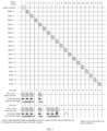
FIG. 3 is a schematic diagram of the principle of a Morse-encoded modulation module of an embodiment of the present invention; -
FIG. 4 is a mapping relationship table of Morse code of an embodiment of the present invention. - To make the features and advantages of the present patent more obvious and easy to understand, the following embodiments are given for detailed illustration.
- The technical solutions of the present invention are further described below in conjunction with the accompanying drawings and embodiment.
- While many specific details are outlined in the following description to facilitate a full understanding of the present invention, the present invention may also be implemented in other ways different from those described herein, and thus the scope of protection of the present invention is not limited by the specific embodiment disclosed below.
- As shown in
FIG. 1 , the present embodiment provides a digital full-bandwidth direct-forwarding racon system and a working method thereof, including the following components of: - (1) a receiving antenna, (2) a radio-frequency receiving link, (3) a baseband processing module, (4) a radio-frequency transmitting link, and (5) a transmitting antenna;
- Where the (1) receiving antenna is configured to receive a radar transmission signal within an operating frequency band range from space;
- The (2) radio-frequency receiving link is configured to filter, amplify, mix, filter, and amplify a radio-frequency signal output by the receiving antenna, and output an intermediate-frequency signal;
- The (3) baseband processing module is configured to perform ADC acquisition, digital down-conversion, Morse encoding modulation, digital up-conversion, and DAC on an intermediate-frequency analog signal output by the radio-frequency receiving link;
- The (4) radio-frequency transmitting link is configured to filter, amplify, mix, filter, and amplify the intermediate-frequency analog signal output by the DAC module of the baseband processing module, and output a radio-frequency signal; and
- The (5) the transmitting antenna is configured to radiate the radio-frequency signal output by the radio-frequency transmitting link to the space.
- In the present embodiment, the connection relationship among the above components is as follows: from (1) to (5), the output of the previous module is connected to the input of the next module, in turn, thus forming the basic composition of the system.
- Each component of the system of the present embodiment is described below:
Antenna system: The antenna system includes a receiving antenna and a transmitting antenna. The operating frequency band range of the antenna covers an entire 200MHz bandwidth operating range of the racon (S-band: 2.9G~3.1G, X-band: 9.3G~9.5G). The receiving antenna is configured to receive a signal transmitted by a radar within an operating frequency band range from space, and the transmitting antenna is configured to radiate a system response signal to the space. Since the transmitting antenna and the receiving antenna need to operate simultaneously, to avoid system self-excitation, the isolation between the transmitting antenna and the receiving antenna must be greater than the total system gain. The system gain is proportional to the response distance. To increase the response distance, the design of high isolation between the transmitting antenna and the receiving antenna is essential for the present system. The two feasible ways of high isolation antenna design are: 1) to optimize the design of parameters and layout of the transmitting antenna and the receiving antenna, 2) to increase the pair of elimination branches, and the above two ways can be combined. One of the transmitting antenna and the receiving antenna needs to be placed above the other, both of which are basically vertical, and the farther apart, the better. To be compact, a radio signal isolation plate can be added between the transmitting antenna and the receiving antenna in the structural design. The isolation plate is made of metal and other materials that have isolation or shielding effects on radio signals. The transmitting antenna and the receiving antenna are placed about in a vertical line or slightly staggered. The isolation plate is generally circular, square, etc. The center of the isolation plate is about on the connecting line of the two antennas and close to the middle position between the two antennas, presenting an approximately horizontal state and being perpendicular to the antenna to avoid the system self-excitation, so that the transmission power can be increased to increase the response distance. - Radio-frequency transceiver module: The radio-frequency transceiver module includes a radio-frequency receiving link and a radio-frequency transmitting link. The operating frequency band range of the radio-frequency receiving link and the radio-frequency transmitting link cover an entire 200MHz bandwidth operating range of the racon (S-band: 2.9G~3.1G, X-band: 9.3G~9.5G). The radio-frequency receiving link and the radio-frequency transmitting link include core devices such as filters, amplifiers, mixers, etc. The radio-frequency receiving link and the radio-frequency transmitting link share the same local oscillator module. The radio-frequency receiving link is configured to convert a radio-frequency signal output by the receiving antenna into an intermediate-frequency signal and output the intermediate-frequency signal to the ADC acquisition module of the baseband processing module, and the radio-frequency transmitting link is configured to convert an intermediate-frequency signal output by the DAC module of the baseband processing module into a radio-frequency signal and output the radio-frequency signal to the transmitting antenna.
- Baseband processing module: The baseband processing module mainly includes an ADC acquisition module, an FPGA processing module, and a DAC module. The ADC acquisition module analog-to-digital converts an intermediate-frequency analog signal output by a radio-frequency receiver to a digital signal and outputs the digital signal to the FPGA processing module. The DAC module converts the digital signal output by the FPGA processing module into an analog signal and transmits the analog signal to an intermediate-frequency analog input interface of a radio-frequency transmitter. The sampling rate configuration for the ADC acquisition module and the DAC module is required to ensure full-frequency band acquisition of a signal within the entire 200MHz bandwidth operating range of the racon. The FPGA processing module is the core module of the system of the present invention, which mainly realizes orthogonal down-conversion processing of data acquired by ADC, envelope detection, Morse encoding modulation, and orthogonal up-conversion processing.
- As shown in
FIGS. 2 to 4 , the Morse encoding system is one of the core processing aspects of the system of the present embodiment, including three parts: a signal delay module, an encoding switch module, and a superimposing module. The encoding system adopts a multi-stage signal delay data superimposing architecture, and delayed signals of multi stages are connected and superimposed to form a delay chain. Delay values of the signal delay in each stage are the same and configurable; each stage of the signal delay can be divided into a multi-level sub delays to optimize the display effect. The signal data (signal length is long enough for radars to recognize) is input into the signal delay module and signal delay data is output to the encoding switch module. The encoding switch module is a switch array, where each channel or stage of the signal delay data corresponds to an on/off switch, and the on/off of the switch is controlled by a Morse-encoded setting value. The Morse-encoded setting value is obtained by looking up a Morse code mapping relationship table compiled by the present invention according to a Morse code symbol. The Morse code mapping relationship is a correspondence table where the Morse code symbol corresponds to the Morse-encoded setting value. The Morse code symbol includes A to Z, 0 to 9, NW, NE, SW, SE. The number of bits of the Morse-encoded setting value and the number of channels of signal delay are the same, arranged from high to low in order. Each one bit of the Morse-encoded setting value is referred to as a basic symbol unit, and each one bit of the Morse-encoded setting value controls an on/off switch in the encoding switch module. The function of the Morse code mapping relationship table is to map the representation of "dot-dash-blank" corresponding to the Morse symbol to the Morse-encoded setting value. The basic principle of the mapping is that a "dot" or a "dash" is represented by 1 and a "blank" is represented by 0 between a "dot-dot", a "dot-dash", a "dash-dot" and a "dash-dash"; the number of bits occupied by the "dot" and the "blank" is the same, the number of bits occupied by the "dash" is three times the number of bits occupied by the "dot" or the "blank", and they occupy the maximum length of data corresponding to the Morse-encoded setting value under the premise of a relative relationship among the "dot", the "dash" and the "blank". The encoding switch module outputs strobe signal delay data to the superimposing module to participate in superimposing, and the superimposing module superimposes all the input delayed signal data into one channel of coded modulated waveform for output. - Radome: Radome is configured to protect other components of the system of the present invention and prevent the environment from affecting and interfering operating statuses of other components. Besides, the design of the radome has a certain influence on the isolation of the transmitting antenna and the receiving antenna of the system of the present invention. Thus the design of the radome and the design of the transmitting antenna and the receiving antenna should be considered comprehensively.
- Based on the above system and the principles involved, as a preference, the present embodiment provides a more specific design and working method under the system architecture:
- 1) Powering up and initializing the system;
- 2) Transmitting a Morse-encoded setting value: 19'b111_1111_1100_0111_0000 (Morse code: N) and a delay value of the signal delay: 500 (corresponding to the length of the basic symbol unit: 500*4ns=2us) to the Morse-encoded modulation module of the baseband processing module;
- 3) Receiving, by the receiving antenna (X: 9.3~9.5G, omnidirectional, horizontally polarized, pitch angle: 22°, gain: 6dBi, the isolation between the transmitting antenna and the receiving antenna: 85dB), a radar transmission signal within an operating frequency band range from space;
- 4) Filtering, amplifying, mixing, filtering, and amplifying, by the radio-frequency receiving link (input: 9.3~9.5GHz, output: 600~800MHz, gain: 30dB), a radio-frequency signal output by the receiving antenna, and outputting an intermediate-frequency signal;
- 5) Analog-to-digital converting, by an ADC acquisition module of a baseband processing module (
sampling rate 1 Gbps), an intermediate-frequency analog signal output by the radio-frequency receiving link to a digital signal (4 parallel channels @250MHz), and outputting the digital signal; - 6) Receiving, by an FPGA processing module of the baseband processing module (FPGA model: xc7v325t-ffg900), the digital signal output by the ADC acquisition module, performing DDC processing on the digital signal (local oscillator frequency: 700MHz, filter bandwidth: 200MHz, 4 taps), and transferring the received signal to a baseband (1 channel signal with a sampling rate of 250Mbps);
- 7) Receiving, by the Morse encoding modulation module in the FPGA processing module, a baseband signal output by a DDC processing module, and performing Morse encoding modulation processing on the baseband signal;
- 8) Receiving, by a DUC module in the FPGA processing module (local oscillator frequency: 700MHz, filter bandwidth: 200MHz, interpolation(s): 4), an output of the Morse encoding modulation module, performing up-conversion on the output, and outputting an intermediate-frequency digital signal (4 parallel channels @250MHz) after processing;
- 9) Digital-to-analog converting, by a DAC module of the baseband processing module, the intermediate-frequency digital signal output by the DUC module of the FPGA processing module into an analog intermediate-frequency signal, and outputting the analog intermediate-frequency signal after processing (1 channel with 600~800MHz);
- 10) Filtering, amplifying, mixing, filtering, and amplifying, by a radio-frequency transmitting link (input: 600~800MHz, output: 9.3~9.5GHz, and gain: 50dB), the intermediate-frequency analog signal output by the DAC module of the baseband processing module, and outputting a radio-frequency signal;
- 11) Radiating, by a transmitting antenna (X: 9.3~9.5G, omnidirectional, horizontally polarized, with pitch angle of 22°, gain of 6dBi, the isolation between the transmitting antenna and the receiving antenna of 85dB), the radio-frequency signal output by the radio-frequency transmitting link to the space.
Claims (5)
- A digital full-bandwidth direct-forwarding racon system, comprising:an antenna system including a receiving antenna and a transmitting antenna;a radio-frequency transceiver module including a radio-frequency receiving link and a radio-frequency transmitting link; anda baseband processing module including ADC acquisition module, an FPGA processing module, and a DAC module;wherein:the receiving antenna is configured to receive a signal transmitted by a radar within an operating frequency band range from space, and the transmitting antenna is configured to radiate a system response signal to the space;the radio-frequency receiving link and the radio-frequency transmitting link share a local oscillator module; the radio-frequency receiving link is configured to convert a radio-frequency signal output by the receiving antenna into an intermediate-frequency signal and output the intermediate-frequency signal to the ADC acquisition module of the baseband processing module; andthe radio-frequency transmitting link is configured to convert an intermediate-frequency signal output by the DAC module of the baseband processing module into a radio-frequency signal and output the radio-frequency signal to the transmitting antenna;the ADC acquisition module converts an intermediate-frequency analog signal output by the radio-frequency receiving link into a digital signal and sends the digital signal to the FPGA processing module; the DAC module converts a digital signal output by the FPGA processing module into an analog signal and sends the analog signal to an intermediate-frequency analog input interface of a radio-frequency transmitter;the FPGA processing module is configured to realize: orthogonal down-conversion processing of data acquired by ADC through a DDC module, envelope detection, Morse encoding modulation, and orthogonal up-conversion processing through a DUC module; modulation being realized through three parts: i) a signal delay module, ii) an encoding switch module, and iii) a superimposing module, so that the Morse encoding modulation module adopts a multi-stage delayed signal superimposing architecture, and delayed signals are connected and superimposed to form a delay chain; where:i) delay values of the signal delay in each stage are the same and adjustable; and the signal data is input into the signal delay module and signal delay data is output to the encoding switch module;ii) the encoding switch module is a switch array, each channel or stage of the signal delay data corresponds to an on/off switch, and the on/off of the switch is controlled by a Morse-encoded setting value; the Morse-encoded setting value is obtained by looking up a Morse code mapping relationship table according to a Morse code symbol; and the encoding switch module outputs strobe signal delay data to the superimposing module to participate in superimposing; andiii) the superimposing module superimposes all the input delayed signals into one channel of coded modulated waveform for output.
- The digital full-bandwidth direct-forwarding racon system according to claim 1, characterized in that the Morse code mapping relationship table maps the representation of "dot-dash-blank" corresponding to the Morse symbol to the Morse-encoded setting value; the basic principle of the mapping is that a "dot" or a "dash" is represented by 1 and a "blank" is represented by 0 between a "dot-dot", a "dot-dash", a "dash-dot" and a "dash-dash"; the number of bits occupied by the "dot" and the "blank" are the same; the number of bits occupied by the "dash" is three times the number of bits occupied by the "dot" or the "blank", and they occupy the maximum length of data corresponding to the Morse-encoded setting value under the premise of a relative relationship among the "dot", the "dash" and the "blank".
- The digital full-bandwidth direct-forwarding racon system according to claim 1, characterized in that an operating frequency band range of the antenna system covers an entire 200MHz bandwidth operating range of the racon, and a degree of isolation between the transmitting antenna and the receiving antenna is greater than a total system gain; an operating frequency band range of the radio-frequency receiving link and the radio-frequency transmitting link covers the entire 200MHz bandwidth operating range of the racon; the radio-frequency receiving link and the radio-frequency transmitting link both comprise: a filter, an amplifier, and a mixer; the sampling rate configuration for the ADC acquisition module and the DAC module is required to ensure full-frequency band acquisition of a signal within the entire 200MHz bandwidth operating range of the racon.
- The digital full-bandwidth direct-forwarding racon system according to claim 1, characterized by further comprising: a radome configured to protect an operating status of each module from being affected and interfered by environment.
- An operating method of the digital full-bandwidth direct-forwarding racon system according to claim 1, comprising the steps of:step S1: powering up and initializing;step S2: receiving, by the receiving antenna, a radar transmission signal within an operating frequency band range from space;step S3: filtering, amplifying, mixing, filtering, and amplifying, by the radio-frequency receiving link, a radio-frequency signal output by the receiving antenna, and outputting an intermediate-frequency signal;step S4: analog-to-digital converting, by the ADC acquisition module of a baseband processing module, an intermediate-frequency analog signal output by the radio-frequency receiving link to a digital signal, and outputting the digital signal;step S5: receiving, by the FPGA processing module of the baseband processing module, the digital signal output by the ADC acquisition module, performing DDC processing on the digital signal, and transferring the received signal to a baseband;step S6: receiving, by the Morse encoding modulation module in the FPGA processing module, a baseband signal output by the DDC module, and performing Morse encoding modulation processing on the baseband signal;step S7: receiving, by the DUC module in the FPGA processing module, an output of the Morse encoding modulation module, performing up-conversion on the output, and outputting an intermediate-frequency digital signal after processing;step S8: digital-to-analog converting, by the DAC module of the baseband processing module, the intermediate-frequency digital signal output by the DUC module of the FPGA processing module into an analog intermediate-frequency signal, and outputting the analog intermediate-frequency signal after processing;step S9: filtering, amplifying, mixing, filtering, and amplifying, by the radio-frequency transmitting link, the intermediate-frequency analog signal output by the DAC module of the baseband processing module, and outputting a radio-frequency signal; andstep S10: radiating, by the transmitting antenna, the radio-frequency signal output by the radio-frequency transmitting link to the space.
Applications Claiming Priority (2)
| Application Number | Priority Date | Filing Date | Title |
|---|---|---|---|
| CN202210215094.9A CN114609588B (en) | 2022-03-07 | 2022-03-07 | Digital full-broadband direct-transfer type radar transponder system and working method thereof |
| PCT/CN2022/081110 WO2023168734A1 (en) | 2022-03-07 | 2022-03-16 | Digital full-broadband direct forwarding type radar transponder system and working method therefor |
Publications (3)
| Publication Number | Publication Date |
|---|---|
| EP4270056A1 EP4270056A1 (en) | 2023-11-01 |
| EP4270056A4 EP4270056A4 (en) | 2024-04-03 |
| EP4270056B1 true EP4270056B1 (en) | 2025-07-02 |
Family
ID=87850076
Family Applications (1)
| Application Number | Title | Priority Date | Filing Date |
|---|---|---|---|
| EP22868453.6A Active EP4270056B1 (en) | 2022-03-07 | 2022-03-16 | Digital full-bandwidth direct-forwarding racon system, and working method therefor |
Country Status (3)
| Country | Link |
|---|---|
| US (1) | US12431959B2 (en) |
| EP (1) | EP4270056B1 (en) |
| ES (1) | ES3040737T3 (en) |
Families Citing this family (1)
| Publication number | Priority date | Publication date | Assignee | Title |
|---|---|---|---|---|
| SE2151399A1 (en) * | 2021-11-17 | 2023-05-18 | Idestam Almquist Peter | A communications system and a method for communicating information |
Family Cites Families (13)
| Publication number | Priority date | Publication date | Assignee | Title |
|---|---|---|---|---|
| US7777667B1 (en) | 1979-12-05 | 2010-08-17 | The United States of America as represented by the Department of the Air Force | Radar target identification apparatus |
| DE19620682C2 (en) | 1995-05-24 | 2001-06-28 | Deutsch Zentr Luft & Raumfahrt | Method for locating and identifying objects using a coded transponder |
| SE515873C2 (en) | 2000-03-01 | 2001-10-22 | Saab Ab | A transponder device |
| US8675781B2 (en) * | 2011-09-08 | 2014-03-18 | Thinkrf Corporation | Radio frequency receiver system for wideband signal processing |
| FR3002098B1 (en) | 2013-02-08 | 2016-04-01 | Thales Sa | TRANSPONDER FOR RADAR DOPPLER, TARGET LOCATION SYSTEM USING SUCH TRANSPONDER |
| JP6198631B2 (en) * | 2014-02-25 | 2017-09-20 | パナソニック株式会社 | Receiving apparatus and demodulation method |
| WO2015149219A1 (en) * | 2014-03-31 | 2015-10-08 | 华为技术有限公司 | Multichannel radio frequency device and method |
| WO2015198753A1 (en) * | 2014-06-26 | 2015-12-30 | 古野電気株式会社 | Signal processing device, transponder device, radar device, and signal processing method |
| CN105629207B (en) * | 2015-12-22 | 2019-02-22 | 南京理工大学 | Radar signal processing system based on DRFM technology and method for generating dense target interference |
| CN109375180A (en) * | 2018-10-23 | 2019-02-22 | 哈尔滨工程大学 | An FPGA Implementation Method of Radar Advance Jamming Based on Intermittent Sampling and Forwarding |
| DE102018130556B4 (en) * | 2018-11-30 | 2024-07-11 | Infineon Technologies Ag | PHASE CALIBRATION FOR FMCW RADAR SYSTEMS |
| CN111289952B (en) | 2020-03-27 | 2023-08-15 | 华清瑞达(天津)科技有限公司 | Radar target echo simulation method and device |
| US20220321241A1 (en) * | 2021-04-06 | 2022-10-06 | At&T Intellectual Property I, L.P. | Method and apparatus for enhancing signal-to-interference-plus-noise ratio (sinr) in a waveguide communication system |
-
2022
- 2022-03-16 EP EP22868453.6A patent/EP4270056B1/en active Active
- 2022-03-16 ES ES22868453T patent/ES3040737T3/en active Active
-
2023
- 2023-02-14 US US18/109,276 patent/US12431959B2/en active Active
Also Published As
| Publication number | Publication date |
|---|---|
| EP4270056A4 (en) | 2024-04-03 |
| EP4270056A1 (en) | 2023-11-01 |
| US12431959B2 (en) | 2025-09-30 |
| ES3040737T3 (en) | 2025-11-04 |
| US20230283356A1 (en) | 2023-09-07 |
Similar Documents
| Publication | Publication Date | Title |
|---|---|---|
| US10551482B2 (en) | Vehicular radar system with self-interference cancellation | |
| WO2023168734A1 (en) | Digital full-broadband direct forwarding type radar transponder system and working method therefor | |
| EP2669700B1 (en) | Electronic counter measure system | |
| CN101609931B (en) | Antenna array phase control technology based on time modulation and system realizing method thereof | |
| RU2413958C2 (en) | Radar apparatus | |
| WO2017187339A1 (en) | Vehicular radar system with self-interference cancellation | |
| CN111370873B (en) | High-efficiency phase modulation system based on time modulation array | |
| US20150285897A1 (en) | Hybrid radar system combining fmcw radar and pulsed radar | |
| US5821895A (en) | Method and device for locating and identifying objects by means of an encoded transponder | |
| CN108051791A (en) | A kind of phased-array radar universal calibration device | |
| CN113534060A (en) | A marine active phased array radar | |
| Galati et al. | Waveforms design for modern and MIMO radar | |
| CN116428922B (en) | An impulse fuze modulation method and system | |
| US12431959B2 (en) | Digital full-bandwidth direct-forwarding racon system and working method thereof | |
| WO2023240957A1 (en) | Digital full-broadband direct-forward-type search and rescue radar transponder system | |
| George et al. | Implementation of blind zone and range-velocity ambiguity mitigation for solid-state weather radar | |
| EP4622097A1 (en) | Signal processing system and related device | |
| CN117233701A (en) | Radar radio frequency receiving method and radar radio frequency system adapting to strong clutter environment | |
| Singh et al. | A programmable, multimode operational 3U-VPX based digital transceiver & processing module for CIT-MKXIIA IFF | |
| Norheim-Næss et al. | VErsatile RAdar–RFSoC based radar demonstrator for multiple applications | |
| Bertuch et al. | System aspects of a low-cost coherent radar system with AESA antenna for maritime applications | |
| Bhargavi et al. | Experimental Evaluation of Various LFM Waveforms for FMCW Radar Applications | |
| CN120254773A (en) | A dual-band pulse compression coding frequency agility anti-interference method and system | |
| Al-Ashwal et al. | Development of an experimental weather radar | |
| Gao et al. | A generic digital transceiver calibration module |
Legal Events
| Date | Code | Title | Description |
|---|---|---|---|
| STAA | Information on the status of an ep patent application or granted ep patent |
Free format text: STATUS: UNKNOWN |
|
| STAA | Information on the status of an ep patent application or granted ep patent |
Free format text: STATUS: THE INTERNATIONAL PUBLICATION HAS BEEN MADE |
|
| PUAI | Public reference made under article 153(3) epc to a published international application that has entered the european phase |
Free format text: ORIGINAL CODE: 0009012 |
|
| STAA | Information on the status of an ep patent application or granted ep patent |
Free format text: STATUS: REQUEST FOR EXAMINATION WAS MADE |
|
| 17P | Request for examination filed |
Effective date: 20230324 |
|
| AK | Designated contracting states |
Kind code of ref document: A1 Designated state(s): AL AT BE BG CH CY CZ DE DK EE ES FI FR GB GR HR HU IE IS IT LI LT LU LV MC MK MT NL NO PL PT RO RS SE SI SK SM TR |
|
| A4 | Supplementary search report drawn up and despatched |
Effective date: 20240304 |
|
| RIC1 | Information provided on ipc code assigned before grant |
Ipc: G01S 13/76 20060101ALI20240227BHEP Ipc: G01S 7/02 20060101ALI20240227BHEP Ipc: G01S 7/00 20060101ALI20240227BHEP Ipc: G01S 13/78 20060101AFI20240227BHEP |
|
| GRAP | Despatch of communication of intention to grant a patent |
Free format text: ORIGINAL CODE: EPIDOSNIGR1 |
|
| STAA | Information on the status of an ep patent application or granted ep patent |
Free format text: STATUS: GRANT OF PATENT IS INTENDED |
|
| RIC1 | Information provided on ipc code assigned before grant |
Ipc: G01S 13/76 20060101ALI20250321BHEP Ipc: G01S 7/02 20060101ALI20250321BHEP Ipc: G01S 7/00 20060101ALI20250321BHEP Ipc: G01S 13/78 20060101AFI20250321BHEP |
|
| DAV | Request for validation of the european patent (deleted) | ||
| DAX | Request for extension of the european patent (deleted) | ||
| INTG | Intention to grant announced |
Effective date: 20250411 |
|
| GRAS | Grant fee paid |
Free format text: ORIGINAL CODE: EPIDOSNIGR3 |
|
| GRAA | (expected) grant |
Free format text: ORIGINAL CODE: 0009210 |
|
| STAA | Information on the status of an ep patent application or granted ep patent |
Free format text: STATUS: THE PATENT HAS BEEN GRANTED |
|
| AK | Designated contracting states |
Kind code of ref document: B1 Designated state(s): AL AT BE BG CH CY CZ DE DK EE ES FI FR GB GR HR HU IE IS IT LI LT LU LV MC MK MT NL NO PL PT RO RS SE SI SK SM TR |
|
| REG | Reference to a national code |
Ref country code: GB Ref legal event code: FG4D |
|
| REG | Reference to a national code |
Ref country code: CH Ref legal event code: EP |
|
| REG | Reference to a national code |
Ref country code: DE Ref legal event code: R096 Ref document number: 602022017110 Country of ref document: DE |
|
| REG | Reference to a national code |
Ref country code: IE Ref legal event code: FG4D |
|
| REG | Reference to a national code |
Ref country code: ES Ref legal event code: FG2A Ref document number: 3040737 Country of ref document: ES Kind code of ref document: T3 Effective date: 20251104 |
|
| REG | Reference to a national code |
Ref country code: NL Ref legal event code: MP Effective date: 20250702 |
|
| PG25 | Lapsed in a contracting state [announced via postgrant information from national office to epo] |
Ref country code: PT Free format text: LAPSE BECAUSE OF FAILURE TO SUBMIT A TRANSLATION OF THE DESCRIPTION OR TO PAY THE FEE WITHIN THE PRESCRIBED TIME-LIMIT Effective date: 20251103 |
|
| PG25 | Lapsed in a contracting state [announced via postgrant information from national office to epo] |
Ref country code: NL Free format text: LAPSE BECAUSE OF FAILURE TO SUBMIT A TRANSLATION OF THE DESCRIPTION OR TO PAY THE FEE WITHIN THE PRESCRIBED TIME-LIMIT Effective date: 20250702 |
|
| REG | Reference to a national code |
Ref country code: AT Ref legal event code: MK05 Ref document number: 1809835 Country of ref document: AT Kind code of ref document: T Effective date: 20250702 |
|
| PG25 | Lapsed in a contracting state [announced via postgrant information from national office to epo] |
Ref country code: IS Free format text: LAPSE BECAUSE OF FAILURE TO SUBMIT A TRANSLATION OF THE DESCRIPTION OR TO PAY THE FEE WITHIN THE PRESCRIBED TIME-LIMIT Effective date: 20251102 |
|
| PG25 | Lapsed in a contracting state [announced via postgrant information from national office to epo] |
Ref country code: NO Free format text: LAPSE BECAUSE OF FAILURE TO SUBMIT A TRANSLATION OF THE DESCRIPTION OR TO PAY THE FEE WITHIN THE PRESCRIBED TIME-LIMIT Effective date: 20251002 |
|
| REG | Reference to a national code |
Ref country code: LT Ref legal event code: MG9D |
|
| PG25 | Lapsed in a contracting state [announced via postgrant information from national office to epo] |
Ref country code: AT Free format text: LAPSE BECAUSE OF FAILURE TO SUBMIT A TRANSLATION OF THE DESCRIPTION OR TO PAY THE FEE WITHIN THE PRESCRIBED TIME-LIMIT Effective date: 20250702 |
|
| PG25 | Lapsed in a contracting state [announced via postgrant information from national office to epo] |
Ref country code: FI Free format text: LAPSE BECAUSE OF FAILURE TO SUBMIT A TRANSLATION OF THE DESCRIPTION OR TO PAY THE FEE WITHIN THE PRESCRIBED TIME-LIMIT Effective date: 20250702 |
|
| PG25 | Lapsed in a contracting state [announced via postgrant information from national office to epo] |
Ref country code: HR Free format text: LAPSE BECAUSE OF FAILURE TO SUBMIT A TRANSLATION OF THE DESCRIPTION OR TO PAY THE FEE WITHIN THE PRESCRIBED TIME-LIMIT Effective date: 20250702 |
|
| PG25 | Lapsed in a contracting state [announced via postgrant information from national office to epo] |
Ref country code: GR Free format text: LAPSE BECAUSE OF FAILURE TO SUBMIT A TRANSLATION OF THE DESCRIPTION OR TO PAY THE FEE WITHIN THE PRESCRIBED TIME-LIMIT Effective date: 20251003 |
|
| PG25 | Lapsed in a contracting state [announced via postgrant information from national office to epo] |
Ref country code: SE Free format text: LAPSE BECAUSE OF FAILURE TO SUBMIT A TRANSLATION OF THE DESCRIPTION OR TO PAY THE FEE WITHIN THE PRESCRIBED TIME-LIMIT Effective date: 20250702 Ref country code: CZ Free format text: LAPSE BECAUSE OF FAILURE TO SUBMIT A TRANSLATION OF THE DESCRIPTION OR TO PAY THE FEE WITHIN THE PRESCRIBED TIME-LIMIT Effective date: 20250702 |
|
| PG25 | Lapsed in a contracting state [announced via postgrant information from national office to epo] |
Ref country code: LV Free format text: LAPSE BECAUSE OF FAILURE TO SUBMIT A TRANSLATION OF THE DESCRIPTION OR TO PAY THE FEE WITHIN THE PRESCRIBED TIME-LIMIT Effective date: 20250702 |
|
| PG25 | Lapsed in a contracting state [announced via postgrant information from national office to epo] |
Ref country code: BG Free format text: LAPSE BECAUSE OF FAILURE TO SUBMIT A TRANSLATION OF THE DESCRIPTION OR TO PAY THE FEE WITHIN THE PRESCRIBED TIME-LIMIT Effective date: 20250702 Ref country code: PL Free format text: LAPSE BECAUSE OF FAILURE TO SUBMIT A TRANSLATION OF THE DESCRIPTION OR TO PAY THE FEE WITHIN THE PRESCRIBED TIME-LIMIT Effective date: 20250702 |
|
| PG25 | Lapsed in a contracting state [announced via postgrant information from national office to epo] |
Ref country code: RS Free format text: LAPSE BECAUSE OF FAILURE TO SUBMIT A TRANSLATION OF THE DESCRIPTION OR TO PAY THE FEE WITHIN THE PRESCRIBED TIME-LIMIT Effective date: 20251002 |
|
| PG25 | Lapsed in a contracting state [announced via postgrant information from national office to epo] |
Ref country code: SM Free format text: LAPSE BECAUSE OF FAILURE TO SUBMIT A TRANSLATION OF THE DESCRIPTION OR TO PAY THE FEE WITHIN THE PRESCRIBED TIME-LIMIT Effective date: 20250702 |
|
| PGFP | Annual fee paid to national office [announced via postgrant information from national office to epo] |
Ref country code: GB Payment date: 20260302 Year of fee payment: 5 |
|
| PG25 | Lapsed in a contracting state [announced via postgrant information from national office to epo] |
Ref country code: DK Free format text: LAPSE BECAUSE OF FAILURE TO SUBMIT A TRANSLATION OF THE DESCRIPTION OR TO PAY THE FEE WITHIN THE PRESCRIBED TIME-LIMIT Effective date: 20250702 |
|
| PGFP | Annual fee paid to national office [announced via postgrant information from national office to epo] |
Ref country code: DE Payment date: 20260302 Year of fee payment: 5 |
|
| PGFP | Annual fee paid to national office [announced via postgrant information from national office to epo] |
Ref country code: IT Payment date: 20260302 Year of fee payment: 5 |
|
| PGFP | Annual fee paid to national office [announced via postgrant information from national office to epo] |
Ref country code: FR Payment date: 20260302 Year of fee payment: 5 |
|
| PG25 | Lapsed in a contracting state [announced via postgrant information from national office to epo] |
Ref country code: SK Free format text: LAPSE BECAUSE OF FAILURE TO SUBMIT A TRANSLATION OF THE DESCRIPTION OR TO PAY THE FEE WITHIN THE PRESCRIBED TIME-LIMIT Effective date: 20250702 Ref country code: EE Free format text: LAPSE BECAUSE OF FAILURE TO SUBMIT A TRANSLATION OF THE DESCRIPTION OR TO PAY THE FEE WITHIN THE PRESCRIBED TIME-LIMIT Effective date: 20250702 |
|
| PLBE | No opposition filed within time limit |
Free format text: ORIGINAL CODE: 0009261 |
|
| STAA | Information on the status of an ep patent application or granted ep patent |
Free format text: STATUS: NO OPPOSITION FILED WITHIN TIME LIMIT |