EP4269948A1 - Anwenderschnittstelle, fortbewegungsmittel und verfahren zur anzeige einer virtuellen dreidimensionalen navigationskarte - Google Patents
Anwenderschnittstelle, fortbewegungsmittel und verfahren zur anzeige einer virtuellen dreidimensionalen navigationskarte Download PDFInfo
- Publication number
- EP4269948A1 EP4269948A1 EP23166480.6A EP23166480A EP4269948A1 EP 4269948 A1 EP4269948 A1 EP 4269948A1 EP 23166480 A EP23166480 A EP 23166480A EP 4269948 A1 EP4269948 A1 EP 4269948A1
- Authority
- EP
- European Patent Office
- Prior art keywords
- transport
- navigation map
- dimensional navigation
- display device
- representation
- Prior art date
- Legal status (The legal status is an assumption and is not a legal conclusion. Google has not performed a legal analysis and makes no representation as to the accuracy of the status listed.)
- Granted
Links
Images


Classifications
-
- G—PHYSICS
- G01—MEASURING; TESTING
- G01C—MEASURING DISTANCES, LEVELS OR BEARINGS; SURVEYING; NAVIGATION; GYROSCOPIC INSTRUMENTS; PHOTOGRAMMETRY OR VIDEOGRAMMETRY
- G01C21/00—Navigation; Navigational instruments not provided for in groups G01C1/00 - G01C19/00
-
- G—PHYSICS
- G01—MEASURING; TESTING
- G01C—MEASURING DISTANCES, LEVELS OR BEARINGS; SURVEYING; NAVIGATION; GYROSCOPIC INSTRUMENTS; PHOTOGRAMMETRY OR VIDEOGRAMMETRY
- G01C21/00—Navigation; Navigational instruments not provided for in groups G01C1/00 - G01C19/00
- G01C21/26—Navigation; Navigational instruments not provided for in groups G01C1/00 - G01C19/00 specially adapted for navigation in a road network
- G01C21/34—Route searching; Route guidance
- G01C21/36—Input/output arrangements for on-board computers
- G01C21/3626—Details of the output of route guidance instructions
- G01C21/3635—Guidance using 3D or perspective road maps
- G01C21/3638—Guidance using 3D or perspective road maps including 3D objects and buildings
-
- B—PERFORMING OPERATIONS; TRANSPORTING
- B63—SHIPS OR OTHER WATERBORNE VESSELS; RELATED EQUIPMENT
- B63B—SHIPS OR OTHER WATERBORNE VESSELS; EQUIPMENT FOR SHIPPING
- B63B49/00—Arrangements of nautical instruments or navigational aids
-
- G—PHYSICS
- G01—MEASURING; TESTING
- G01C—MEASURING DISTANCES, LEVELS OR BEARINGS; SURVEYING; NAVIGATION; GYROSCOPIC INSTRUMENTS; PHOTOGRAMMETRY OR VIDEOGRAMMETRY
- G01C21/00—Navigation; Navigational instruments not provided for in groups G01C1/00 - G01C19/00
- G01C21/26—Navigation; Navigational instruments not provided for in groups G01C1/00 - G01C19/00 specially adapted for navigation in a road network
- G01C21/34—Route searching; Route guidance
- G01C21/36—Input/output arrangements for on-board computers
- G01C21/3626—Details of the output of route guidance instructions
-
- G—PHYSICS
- G01—MEASURING; TESTING
- G01C—MEASURING DISTANCES, LEVELS OR BEARINGS; SURVEYING; NAVIGATION; GYROSCOPIC INSTRUMENTS; PHOTOGRAMMETRY OR VIDEOGRAMMETRY
- G01C21/00—Navigation; Navigational instruments not provided for in groups G01C1/00 - G01C19/00
- G01C21/26—Navigation; Navigational instruments not provided for in groups G01C1/00 - G01C19/00 specially adapted for navigation in a road network
- G01C21/34—Route searching; Route guidance
- G01C21/36—Input/output arrangements for on-board computers
- G01C21/3626—Details of the output of route guidance instructions
- G01C21/365—Guidance using head up displays or projectors, e.g. virtual vehicles or arrows projected on the windscreen or on the road itself
-
- G—PHYSICS
- G01—MEASURING; TESTING
- G01C—MEASURING DISTANCES, LEVELS OR BEARINGS; SURVEYING; NAVIGATION; GYROSCOPIC INSTRUMENTS; PHOTOGRAMMETRY OR VIDEOGRAMMETRY
- G01C21/00—Navigation; Navigational instruments not provided for in groups G01C1/00 - G01C19/00
- G01C21/26—Navigation; Navigational instruments not provided for in groups G01C1/00 - G01C19/00 specially adapted for navigation in a road network
- G01C21/34—Route searching; Route guidance
- G01C21/36—Input/output arrangements for on-board computers
- G01C21/3664—Details of the user input interface, e.g. buttons, knobs or sliders, including those provided on a touch screen; remote controllers; input using gestures
-
- G—PHYSICS
- G02—OPTICS
- G02B—OPTICAL ELEMENTS, SYSTEMS OR APPARATUS
- G02B27/00—Optical systems or apparatus not provided for by any of the groups G02B1/00 - G02B26/00, G02B30/00
- G02B27/01—Head-up displays
-
- G—PHYSICS
- G06—COMPUTING OR CALCULATING; COUNTING
- G06F—ELECTRIC DIGITAL DATA PROCESSING
- G06F3/00—Input arrangements for transferring data to be processed into a form capable of being handled by the computer; Output arrangements for transferring data from processing unit to output unit, e.g. interface arrangements
- G06F3/01—Input arrangements or combined input and output arrangements for interaction between user and computer
- G06F3/011—Arrangements for interaction with the human body, e.g. for user immersion in virtual reality
-
- G—PHYSICS
- G06—COMPUTING OR CALCULATING; COUNTING
- G06F—ELECTRIC DIGITAL DATA PROCESSING
- G06F3/00—Input arrangements for transferring data to be processed into a form capable of being handled by the computer; Output arrangements for transferring data from processing unit to output unit, e.g. interface arrangements
- G06F3/01—Input arrangements or combined input and output arrangements for interaction between user and computer
- G06F3/017—Gesture based interaction, e.g. based on a set of recognized hand gestures
-
- G—PHYSICS
- G06—COMPUTING OR CALCULATING; COUNTING
- G06F—ELECTRIC DIGITAL DATA PROCESSING
- G06F3/00—Input arrangements for transferring data to be processed into a form capable of being handled by the computer; Output arrangements for transferring data from processing unit to output unit, e.g. interface arrangements
- G06F3/14—Digital output to display device ; Cooperation and interconnection of the display device with other functional units
-
- G—PHYSICS
- G06—COMPUTING OR CALCULATING; COUNTING
- G06F—ELECTRIC DIGITAL DATA PROCESSING
- G06F9/00—Arrangements for program control, e.g. control units
- G06F9/06—Arrangements for program control, e.g. control units using stored programs, i.e. using an internal store of processing equipment to receive or retain programs
- G06F9/44—Arrangements for executing specific programs
- G06F9/451—Execution arrangements for user interfaces
-
- G—PHYSICS
- G02—OPTICS
- G02B—OPTICAL ELEMENTS, SYSTEMS OR APPARATUS
- G02B27/00—Optical systems or apparatus not provided for by any of the groups G02B1/00 - G02B26/00, G02B30/00
- G02B27/01—Head-up displays
- G02B27/0101—Head-up displays characterised by optical features
- G02B2027/0141—Head-up displays characterised by optical features characterised by the informative content of the display
Definitions
- the present invention relates to a means of transport, a user interface and a method for displaying a virtual three-dimensional navigation map in a means of transport.
- the present invention relates to a particularly intuitively understandable representation of a navigation project and an intuitively understandable guidance of a user on a route.
- Navigation systems in means of transportation usually use display elements permanently located in the instrument cluster, in a central information display and/or in a head-up display.
- the representation presents the (inexperienced) user with difficulties in interpreting, as the details are shown comparatively small and rotated compared to reality. This is particularly due to the fact that the display devices installed in means of transport usually have a vertical rather than horizontal orientation, while the road map would naturally be best understood horizontally.
- augmented reality displays are known, through which users can be shown artificial/virtual content in a predefined relationship to translucent reality. To do this, it is necessary for the augmented reality glasses/display to get to know the environment or for a connection to be established between the display content and reality. Only then can the display elements be displayed in a quasi-contact manner with respect to the environment and used to improve the user's information situation.
- the above-mentioned object is achieved according to the invention by a method for displaying a virtual three-dimensional navigation map in a means of transport.
- the three-dimensional navigation map can be present as a data model in a data memory of the means of transport or can be gradually streamed into the means of transport.
- the three-dimensional navigation map can also be stored in a local data storage of an augmented reality (hereinafter also “AR”) display device.
- AR augmented reality
- the augmented reality display device is located in the means of transport and can be able to optically scan a surface of the interior of the means of transport, in particular a dashboard of the means of transport, or to store a data set representing the surface. This process can also be understood as calibration of the augmented reality display device to the interior surface of the means of transport.
- the augmented reality display device is made aware of a spatial relationship between the surfaces of the interior of the means of transport and the position of the augmented reality display device or is established in such a way that the augmented reality display device determines its own position and the position of the respective surface areas of the interior learned.
- the augmented reality display device is, so to speak, taught to assign certain environmental areas to the surface of the interior of the means of transport, while other areas (e.g. window surfaces) are assigned to an inertial system located outside the means of transport.
- a three-dimensional navigation map is loaded from a data memory.
- This data storage can be provided within the means of transport, in particular within the augmented reality display device and/or outside the means of transport.
- An information technology connection over-the-air (via WiFi, WLAN, LTE, LTE-A, etc.) can be provided, particularly for data storage located outside the means of transport.
- the three-dimensional navigation map or the 3D map model can be adapted to the surface of the means of transport.
- the navigation map can adhere "virtually" over the entire surface to a curved surface of an interior of the means of transport, while the three-dimensional navigation map is usually defined and displayed in the plane (e.g. screen plane or similar).
- the adapted three-dimensional navigation map, along with a representation of an ego position of the means of transport, is then displayed as a virtual, raised model on the surface using the Augmented reality display device shown.
- the navigation map can be displayed in a particularly large size on the dashboard, as there is comparatively much space here and the size of the screens in the vehicle is no longer a limiting factor.
- the essentially horizontal alignment of the majority of the areas of the dashboard is suitable for generating a particularly intuitively understandable representation of the road map, since the viewer does not need to make any perspective adjustment/interpretation.
- a particularly intuitively understandable 3D design of the road map can be made via the augmented reality display device, so that the viewer receives a realistic and perspectively realistic display of the surroundings of the ego vehicle.
- the surface in the interior of the means of transport can be optically scanned in a previous step.
- This step can also be understood as scanning or measuring/locating the surface of the interior. It can take place (automatically) in the respective vehicle, for example after a first pairing of an augmented reality display device with the means of transport. Alternatively or additionally, this step may have been performed at the factory to provide an initial model for the surface.
- This model can, for example, be stored in the augmented reality display device, transmitted to it by the means of transport or kept available for download from a server.
- the scanning process can also be carried out using a smartphone carried by the user. The scanning step can be carried out every time the means of transport and/or the augmented reality display device is put into operation in order to be able to correspond to any changes in function, geometry and color of the surface that may have been made in the meantime.
- the optical scanning of the surface of the interior of the means of transport can be carried out in particular by means of an optical sensor of the display device.
- the augmented reality display device has an optical sensor which is arranged in a housing of the AR display device. In this way, a fixed relationship is always maintained between the alignment of the optical sensor and the display surface.
- a handshake or calibration process can be started in order to get to know the surfaces of the means of transport or its interior and to create a kind of "canvas" for the later display of the adapted three-dimensional navigation map.
- the optical sensor can, for example, be a camera which is oriented in a pair of AR glasses in a direction similar to the user's line of sight. This means that the area that the user sees during use can always be optically recorded using the optical sensor. This means that objects in the user's field of vision can also be recognized and/or parts of the user's body can be identified and/or visually highlighted as input means.
- the AR display device can in particular have a transparent screen, which can be designed, for example, as a head-mounted monitor in the form of a pixel display.
- the display device can also have a smartphone, a tablet or similar, the camera of which provides data for displaying the real background on the screen, while the processor expands (augments) the camera image with additional display content or the adapted three-dimensional navigation map. .
- the three-dimensional navigation map can, for example, be loaded from a data memory of the means of transport.
- the means of transport can be set up to support the navigation project through sensors of the means of transport (in particular wheel speed sensors, GPS antenna(s) or similar).
- the required sections of the three-dimensional navigation map can be made available to the augmented reality display device by the means of transport.
- a navigation system located in the augmented reality display device can also be used, which obtains map data from the means of transport or another data storage and uses its own sensors to determine position and progress. This has the advantage that the navigation project can be continued even after getting out of the means of transport without being able to use wheel speed sensors or a projection according to the invention onto a dashboard.
- the AR display device can be linked to the means of transport in terms of information technology.
- a cable in particular USB or monitor cable
- an antenna can be used to transmit wireless information signals (in particular via Bluetooth, WiFi, WLAN or similar).
- the means of transport can communicate with the AR display device and vice versa.
- sensor information, map data and information about the respective operating status can be exchanged in order to be able to react if necessary.
- a change in the visual appearance of the means of transport in the area of the surface used to display the adapted three-dimensional navigation map can be determined by other circumstances.
- a display element of the means of transport in particular a disk root display or a display device located in the dashboard, can be put into operation or operated with a different intensity and/or with a different content.
- the adapted three-dimensional navigation map and/or its representation can be adapted using the AR display device.
- content can be moved to a different position on the surface of the vehicle interior.
- an intensity and/or a color of a displayed element of the adapted three-dimensional navigation map can be changed in order to prevail over the modified optical appearance of the means of transport or not to disturb the same.
- the means of transport which naturally becomes the first to know what changes occur with regard to its signaling devices, can send a wireless message to the AR display device.
- the AR display device can use its own optical sensor to determine the modified optical appearance of the means of transport in the area of the surface and, independently of communication with the means of transport, make a suitable adjustment to the display of the adapted three-dimensional navigation map. This enables a particularly unproblematic coexistence of the display device of the means of transport and the adapted three-dimensional navigation map.
- a navigation project can be supported particularly intuitively by automatically determining an upcoming maneuver by the means of transport.
- such events are usually supported by detailed representations and/or the issuance of acoustic instructions to the driver.
- the representation of the ego position of the means of transport is created from the adapted three-dimensional navigation map detached.
- a cursor or note that initially coincides with the representation of the ego position is optically lifted upwards and transferred from the adapted three-dimensional navigation map located in the means of transport to the vehicle environment.
- the ego position or a pointer that initially correlates with it rises from the surface and locates itself in a contact-analogous manner with the position of the real vehicle environment at which the maneuver is to be carried out.
- This can mean, for example, that from the dashboard of the means of transport, a representation of the ego position is initially displayed in a vertical (Z direction) ascending cursor overlapping the windshield at such a position using the AR display device, which corresponds to an intersection at which the Means of transport has to turn, visually corresponds.
- the representation or the element emerging from the adapted three-dimensional navigation map can undergo a change in shape and/or a change in color and/or a change in intensity in order to make it clear to the user that, strictly speaking, it is no longer the ego position, but a future target position. Ego position or a directional arrow or similar is represented.
- the display of the three-dimensional navigation map can be automatically adjusted accordingly, so that the viewer sees a rotational movement of the navigation map on the surface, in particular parallel to the external environment. This may depend in particular on the preselected “Map Directional” setting.
- this rotation can also take place with a time offset so that the driver is not distracted by the rotation during a driving maneuver.
- the user may interact with the elements of the customized three-dimensional navigation map.
- the user can tap on a building or its representation in order to display information relating to the building using the augmented reality display device.
- the information can be displayed on the surface of the 3D representation of the respective building and/or illustrated via a text field floating above the building or its representation.
- the information can also alternatively or additionally be assigned to the real building in the area using the AR display device.
- the building of interest to the user is thus selected within the adapted three-dimensional navigation map and is determined in particular by means of the optical sensor of the AR display device, while the information is displayed either in the 3D representation of the building and/or in a contact-like manner on the (real) environment of the means of transport are displayed.
- a user interface for displaying a virtual three-dimensional navigation map in a means of transportation includes a data input, an evaluation unit and a data output.
- the aforementioned elements can, for example, be designed as components of an electronic control device, which can be provided exclusively for the implementation of the present invention in the means of transport or can be provided as hardware shared with other functions.
- the user interface is set up to optically scan a surface of an interior of the means of transport or to obtain a data representation of the same using the data input (and an optical sensor).
- the surface of the interior is optically scanned/located/localized in terms of position and shape or the user interface is calibrated accordingly in order to load a three-dimensional navigation map and adapt it to the surface in terms of data technology.
- the adapted three-dimensional navigation map along with a representation of an ego position of the means of transport, can be displayed as a virtual, raised model on the surface using an AR display device.
- the AR display device can have a transparent screen, which is part of the user interface or is linked to it in terms of information technology via the data output.
- the user interface is set up to implement the features, combinations of features and the resulting advantages of the method according to the invention in such a way that reference is made to the first-mentioned aspect of the invention in order to avoid repetition.
- a means of transport which can be designed, for example, as a car, van, truck, motorcycle, aircraft and/or watercraft.
- the means of transport has a User interface according to the second-mentioned aspect of the invention and is therefore able to support a navigation project of a user of the means of transport with the same features, combinations of features and advantages.
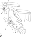
- Figure 1 shows a driver's workplace of a means of transport 10 designed according to the invention in the form of a car, on whose passenger seat an occupant 4 in the form of a passenger has taken a seat.
- the occupant 4 carries an AR display device 2, which has an optical sensor 3 in the form of a 2D camera that is essentially aligned in the direction of view.
- the optical sensor 3 is connected in terms of information technology to the data input 8 of an electronic control device 9.
- a data memory 5 located in the AR display device 2 is also connected in terms of information technology via the data input 8. This can be determined via a data output 11 using the electronic control device 9 Image material can be displayed on the AR display device 2.
- three-dimensional navigation map material sent from a control unit 9 of the means of transport via an antenna 13 of the means of transport is sent to the AR display device 2 and is virtually located on the dashboard 1 of the means of transport 10 in such a way that one of the curved surfaces of the dashboard 1 is adapted Representation of a 3D map model in the form of an adapted three-dimensional navigation map 6 results.
- a representation 7 of an ego position of the means of transport 10 is shown within the adapted three-dimensional navigation map 6.
- a limb 12 of the occupant 4 in the form of a hand has been detected in the detection range of the optical sensor 3.
- the occupant 4 points to a representation of a building within the adapted three-dimensional navigation map 6.
- information relating to the building is displayed using the augmented reality display device 2 in a contact-analogous manner to the representation of the building (not shown ).
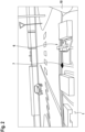
- Figure 2 shows the occupant's view (reference number 4 in Figure 1 ) while approaching a T-junction.
- the ego position of the means of transport 10 is marked in the adapted three-dimensional navigation map 6 by a representation 7.
- Figure 3 shows the in Figure 2 Situation shown after a further approach of the means of transport 10 to the T-junction.
- a modified representation 7' of the means of transport 10 has passed into the (real) environment of the ego means of transport 10 as the future ego position of the means of transport 10.
- the modified representation 7' now virtually "flies" ahead of the means of transport 10 and thereby changes its size and shape.
- Figure 4 shows the in Figure 3 situation shown after the modified representation 7 'has reached' a predefined turning position. At this position, a further modified representation 7" is shown in the form of an arrowhead, which indicates the left-turn maneuver for the driver of the means of transport 10 at the predefined position in the environment announces.
- a manual driving mode or a manually guided means of transport 10 the user now has to reduce the speed and turn the steering to the left.
- an autonomously driving means of transport 10 the user is simply informed that the means of transport 10 will now brake and turn to the left.
- autonomous Moving means of transport 10 is thereby effectively prevented from kinetosis, since the user can adjust to the expected forces.
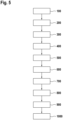
- FIG. 5 shows steps of an exemplary embodiment of a method according to the invention for displaying a virtual three-dimensional navigation map in a means of transport.
- an augmented reality (AR) display device is connected to the means of transport in terms of information technology.
- a wireless communication connection is established between the AR display device and the means of transport.
- a surface of an interior of the means of transport is optically scanned using an optical sensor of the AR display device.
- the AR display device creates a surface model of the interior of the means of transport.
- a three-dimensional navigation map is loaded from a data storage.
- the loaded three-dimensional navigation map is adapted to the surface of the means of transport according to the result of the scanning.
- a curvature of the three-dimensional navigation map is created in order to achieve a full-surface virtual correspondence of the three-dimensional navigation map with the surface of the interior.
- the adapted three-dimensional navigation map together with a representation of an ego position of the means of transport, is displayed as a virtual, raised model on the surface of the means of transport using an augmented reality (AR) display device.
- AR augmented reality
- a modification of an optical appearance of the means of transport in the area of the surface is then determined.
- the means of transport can report that a display in a disk root display could cause an overlay with contents of the adapted three-dimensional navigation map.
- step 700 the adapted three-dimensional navigation map is therefore shifted in order to be able to display the content displayed in the disk root display without being overlaid by the content of the AR display device.
- step 800 an impending maneuver for the means of transport is automatically determined.
- step 900 a representation of the ego position is first copied from the adapted three-dimensional navigation map and then removed.
- step 1000 the extracted representation of the ego position is superimposed on a detail of the environment of the means of transport in a contact-like manner, so that the user can directly see the extracted representation as the environmental position at which the upcoming maneuver is to be carried out.
Landscapes
- Engineering & Computer Science (AREA)
- Radar, Positioning & Navigation (AREA)
- Remote Sensing (AREA)
- Physics & Mathematics (AREA)
- Automation & Control Theory (AREA)
- General Physics & Mathematics (AREA)
- Theoretical Computer Science (AREA)
- General Engineering & Computer Science (AREA)
- Human Computer Interaction (AREA)
- Software Systems (AREA)
- Optics & Photonics (AREA)
- Chemical & Material Sciences (AREA)
- Combustion & Propulsion (AREA)
- Mechanical Engineering (AREA)
- Ocean & Marine Engineering (AREA)
- Navigation (AREA)
- Instructional Devices (AREA)
Abstract
Description
- Die vorliegende Erfindung betrifft ein Fortbewegungsmittel, eine Anwenderschnittstelle sowie ein Verfahren zur Anzeige einer virtuellen dreidimensionalen Navigationskarte in einem Fortbewegungsmittel. Insbesondere betrifft die vorliegende Erfindung eine besonders intuitiv verständliche Darstellung eines Navigationsvorhabens und einer intuitiv verständlichen Führung eines Anwenders auf einer Route.
- Navigationssysteme in Fortbewegungsmitteln verwenden üblicherweise fest im Kombiinstrument, in einem zentralen Informationsdisplay und/oder in einem Head-up-Display verortete Anzeigeelemente. Mitunter stellt die Darstellung den (unerfahrenen) Anwender vor Interpretationsschwierigkeiten, da die Details vergleichsweise klein und gegenüber der Realität gedreht dargestellt werden. Dies liegt insbesondere daran, dass die in Fortbewegungsmitteln verbauten Anzeigeeinrichtungen üblicherweise eine eher vertikale als horizontale Ausrichtung haben, während die Straßenkarte natürlicherweise horizontal orientiert am besten zu verstehen wäre.
- Darüber hinaus sind Augmented-Reality-Anzeigen bekannt, mittels welcher Anwendern künstliche/virtuelle Inhalte in vordefiniertem Bezug zur durchscheinenden Realität angezeigt werden können. Hierzu ist es erforderlich, dass die Augmented-Reality-Brille/-Anzeige die Umgebung kennenlernt, bzw. einen Bezug zwischen den Anzeigeinhalten und der Realität hergestellt wird. Nur dann können die Anzeigeelemente quasi kontaktanalog bezüglich der Umgebung angezeigt und zur Verbesserung der Informationslage des Anwenders verwendet werden.
- Ausgehend vom vorgenannten Stand der Technik ist es eine Aufgabe der vorliegenden Erfindung, einen Anwender bei einem Navigationsvorhaben bestmöglich zu unterstützen.
- Die vorstehend genannte Aufgabe wird erfindungsgemäß durch ein Verfahren zur Anzeige einer virtuellen dreidimensionalen Navigationskarte in einem Fortbewegungsmittel gelöst. Die dreidimensionale Navigationskarte kann als Datenmodell in einem Datenspeicher des Fortbewegungsmittels vorliegen oder nach und nach in das Fortbewegungsmittel gestreamt werden. Alternativ oder zusätzlich kann die dreidimensionale Navigationskarte auch in einem lokalen Datenspeicher einer Augmented-Reality (nachfolgend auch "AR")-Anzeigeeinrichtung abgespeichert sein. Die Augmented-Reality-Anzeigeeinrichtung befindet sich im Fortbewegungsmittel und kann im Stande sein, eine Oberfläche des Innenraums des Fortbewegungsmittels, insbesondere ein Armaturenbrett des Fortbewegungsmittels, optisch abzutasten oder einen die Oberfläche repräsentierenden Datensatz zu speichern. Dieser Vorgang kann auch als Kalibrierung der Augmented-Reality-Anzeigeeinrichtung auf die Innenraumoberfläche des Fortbewegungsmittels verstanden werden. Hierbei wird der Augmented-Reality-Anzeigeeinrichtung eine räumliche Beziehung zwischen den Oberflächen des Innenraums des Fortbewegungsmittels und der Position der Augmented-Reality-Anzeigeeinrichtung zur Kenntnis gebracht oder derart hergestellt, dass die Augmented-Reality-Anzeigeeinrichtung die eigene Position sowie die Position der jeweiligen Oberflächenbereiche des Innenraums erlernt. Hierbei wird der Augmented-Reality-Anzeigeeinrichtung sozusagen beigebracht, bestimmte Umgebungsbereiche der Oberfläche des Innenraumes des Fortbewegungsmittels zuzuordnen, während andere Bereiche (z. B. Fensterflächen) einem außerhalb des Fortbewegungsmittels gelegenen Inertialsystem zugeordnet werden. Zudem wird eine dreidimensionale Navigationskarte aus einem Datenspeicher geladen. Dieser Datenspeicher kann innerhalb des Fortbewegungsmittels, insbesondere innerhalb der Augmented-Reality-Anzeigeeinrichtung und/oder außerhalb des Fortbewegungsmittels vorgesehen sein. Insbesondere für außerhalb des Fortbewegungsmittels befindliche Datenspeicher kann eine informationstechnische Anbindung Over-the-Air (via WiFi, WLAN, LTE, LTE-A etc.) vorgesehen sein.
- Aufgrund der optischen Abtastung bzw. Kalibrierung ist die Gestalt/Form der Oberfläche des Innenraums des Fortbewegungsmittels bekannt. Nun kann die dreidimensionale Navigationskarte bzw. das 3D-Kartenmodell an die Oberfläche des Fortbewegungsmittels angepasst werden. Mit anderen Worten kann die Navigationskarte also vollflächig an einer auch gewölbt ausgestalteten Oberfläche eines Innenraums des Fortbewegungsmittels "virtuell" anhaften, während die dreidimensionale Navigationskarte üblicherweise in der Ebene (z. B. Bildschirmebene o. ä.) definiert ist und angezeigt wird. Anschließend wird die angepasste dreidimensionale Navigationskarte nebst einer Repräsentation einer Ego-Position des Fortbewegungsmittels als virtuelles, erhabenes Modell auf der Oberfläche mittels der Augmented-Reality-Anzeigeeinrichtung dargestellt. Hierbei wird wie bei bekannten Navigationsdarstellungen üblich entweder die Ego-Position des Fortbewegungsmittels durch die Straßen geführt oder die Ego-Position des Fortbewegungsmittels festgehalten, während die angepasste dreidimensionale Navigationskarte entsprechend der Bewegung des realen Fortbewegungsmittels verschoben wird. Diese Darstellungsform hat mehrere Vorteile: Einerseits kann eine besonders große Darstellung der Navigationskarte auf dem Armaturenbrett erfolgen, da hier vergleichsweise viel Platz ist und die Größe im Fortbewegungsmittel befindlicher Bildschirme keinen limitierenden Faktor mehr darstellen. Andererseits ist die im Wesentlichen horizontale Ausrichtung der überwiegenden Bereiche des Armaturenbrettes dafür geeignet, eine besonders intuitiv verständliche Darstellung der Straßenkarte zu erzeugen, da der Betrachter keine perspektivische Anpassung/Interpretation vorzunehmen braucht. Zudem kann über die Augmented-Reality-Anzeigeeinrichtung eine besonders intuitiv verständliche 3D-Gestalt der Straßenkarte vorgenommen werden, sodass der Betrachter eine realitätsgetreue und perspektivisch realitätsnahe Anzeige der Umgebung des Ego-Fortbewegungsmittels erhält.
- Die Unteransprüche zeigen bevorzugte Weiterbildungen der Erfindung.
- Wie oben bereits angesprochen, kann in einem vorausgehenden Schritt die Oberfläche im Innenraum des Fortbewegungsmittels optisch abgetastet werden. Dieser Schritt kann auch als Scannen bzw. Vermessen/Lokalisieren der Oberfläche des Innenraums verstanden werden. Er kann im jeweiligen Fahrzeug (automatisch) erfolgen, beispielsweise nach einem ersten Pairing einer Augmented-Reality-Anzeigeeinrichtung mit dem Fortbewegungsmittel. Alternativ oder zusätzlich kann dieser Schritt werksseitig durchgeführt worden sein, um ein initiales Modell für die Oberfläche bereitzustellen. Dieses Modell kann beispielsweise in der Augmented-Reality-Anzeigeeinrichtung hinterlegt, ihr vom Fortbewegungsmittel übermittelt oder von einem Server herunterladbar bereitgehalten werden. Der Scanvorgang kann beispielsweise auch durch ein vom Anwender mitgeführtes Smartphone durchgeführt werden. Der Schritt des Scannens kann bei jeder Inbetriebnahme des Fortbewegungsmittels und/oder der Augmented-Reality-Anzeigeeinrichtung ausgeführt werden, um zwischenzeitlich ggf. vorgenommenen Änderungen in Funktion, Geometrie und Farbe der Oberfläche entsprechen zu können.
- Die optische Abtastung der Oberfläche des Innenraums des Fortbewegungsmittels kann insbesondere mittels eines optischen Sensors der Anzeigeeinrichtung erfolgen. Mit anderen Worten weist die Augmented-Reality-Anzeigeeinrichtung einen optischen Sensor auf, welcher in einem Gehäuse der AR-Anzeigeeinrichtung angeordnet ist. Auf diese Weise ist auch stets ein fester Bezug zwischen der Ausrichtung des optischen Sensors und der Anzeigefläche gewahrt. So kann beim erstmaligen Verwenden der AR-Anzeigeeinrichtung in dem Fortbewegungsmittel ein Handshake bzw. Kalibriervorgang gestartet werden, um die Oberflächen des Fortbewegungsmittels bzw. seines Innenraums kennenzulernen und eine Art "Leinwand" für die spätere Darstellung der angepassten dreidimensionalen Navigationskarte zu erstellen. Der optische Sensor kann beispielsweise eine Kamera sein, welche in einer AR-Brille in zur Blickrichtung des Anwenders ähnlicher Richtung orientiert ist. Somit kann mittels des optischen Sensors stets derjenige Bereich optisch erfasst werden, welchen der Anwender während der Verwendung erblickt. Somit können auch Gegenstände im Blickfeld des Anwenders erkannt und/oder Körperteile des Anwenders als Eingabemittel identifiziert und/oder optisch hervorgehoben werden.
- Die AR-Anzeigeeinrichtung kann insbesondere einen transparenten Bildschirm aufweisen, welcher beispielsweise als am Kopf befestigter Monitor in Form einer Pixelanzeige ausgestaltet sein kann. Alternativ oder zusätzlich kann die Anzeigeeinrichtung auch ein Smartphone, ein Tablet o. ä. aufweisen, dessen Kamera Daten zur Abbildung des realen Hintergrunds auf dem Bildschirm liefert, während der Prozessor das Kamerabild um zusätzliche Anzeigeinhalte bzw. die angepasste dreidimensionale Navigationskarte, erweitert (augmentiert).
- Die dreidimensionale Navigationskarte kann beispielsweise aus einem Datenspeicher des Fortbewegungsmittels geladen werden. Insbesondere kann das Fortbewegungsmittel eingerichtet sein, das Navigationsvorhaben durch Sensoren des Fortbewegungsmittels (insbesondere Raddrehzahlsensoren, GPS-Antenne(n) o. ä.) zu unterstützen. Die erforderlichen Ausschnitte der dreidimensionalen Navigationskarte können entsprechend durch das Fortbewegungsmittel der Augmented-Reality-Anzeigeeinrichtung zur Verfügung gestellt werden. Alternativ oder zusätzlich kann auch ein in der Augmented-Reality-Anzeigeeinrichtung befindliches Navigationssystem verwendet werden, welches Kartendaten aus dem Fortbewegungsmittel oder einem anderen Datenspeicher bezieht und die eigenen Sensoren für die Ermittlung von Position und Fortschritt verwendet. Dies hat den Vorteil, dass auch nach einem Aussteigen aus dem Fortbewegungsmittel das Navigationsvorhaben fortgesetzt werden kann, ohne Raddrehzahlsensoren oder eine erfindungsgemäße Projektion auf ein Armaturenbrett vornehmen zu können.
- In einem ersten Schritt kann die AR-Anzeigeeinrichtung mit dem Fortbewegungsmittel informationstechnisch verknüpft werden. Hierzu kann ein Kabel (insbesondere USB- oder Monitorkabel) und/oder eine Antenne zur Übertragung drahtloser Informationssignale (insbesondere via Bluetooth, WiFi, WLAN o. ä.) verwendet werden. Nach der informationstechnischen Verknüpfung kann das Fortbewegungsmittel mit der AR-Anzeigeeinrichtung kommunizieren und anders herum.
- Insbesondere können Sensorinformationen, Kartendaten und Informationen über den jeweiligen Betriebszustand ausgetauscht werden, um erforderlichenfalls darauf reagieren zu können. Beispielsweise kann eine Veränderung einer optischen Erscheinung des Fortbewegungsmittels im Bereich der für die Darstellung der angepassten dreidimensionalen Navigationskarte verwendeten Oberfläche durch anderweitige Umstände ermittelt werden. Beispielsweise kann ein Anzeigeelement des Fortbewegungsmittels, insbesondere ein Scheibenwurzeldisplay oder eine in dem Armaturenbrett befindliche Anzeigeeinrichtung in Betrieb genommen oder mit einer anderen Intensität und/oder mit einem anderen Inhalt betrieben werden. Um zu verhindern, dass die modifizierte optische Erscheinung die optische Darstellung der angepassten dreidimensionalen Navigationskarte kompromittiert bzw. mit dieser interferiert, kann die angepasste dreidimensionale Navigationskarte und/oder ihre Darstellung mittels der AR-Anzeigeeinrichtung angepasst werden. Beispielsweise können Inhalte an eine andere Position auf der Oberfläche des Fortbewegungsmittelinnenraums verschoben werden. Alternativ oder zusätzlich kann eine Intensität und/oder eine Farbe eines dargestellten Elementes der angepassten dreidimensionalen Navigationskarte verändert werden, um sich gegenüber der modifizierten optischen Erscheinung des Fortbewegungsmittels durchzusetzen oder selbige nicht zu stören. Zur Ermittlung der modifizierten optischen Erscheinung kann das Fortbewegungsmittel, welches naturgemäß als erstes Kenntnis darüber erlangt, welche Veränderungen sich bezüglich seiner Signalisierungseinrichtungen ergeben, eine Drahtlosnachricht an die AR-Anzeigeeinrichtung senden. Alternativ oder zusätzlich kann die AR-Anzeigeeinrichtung mittels eines eigenen optischen Sensors die modifizierte optische Erscheinung des Fortbewegungsmittels im Bereich der Oberfläche ermitteln und unabhängig von einer Kommunikation mit dem Fortbewegungsmittel eine geeignete Anpassung der Darstellung der angepassten dreidimensionalen Navigationskarte vornehmen. Dies ermöglicht eine besonders unproblematische Koexistenz von Anzeigeeinrichtung des Fortbewegungsmittels und der angepassten dreidimensionalen Navigationskarte.
- Besonders intuitiv kann ein Navigationsvorhaben dadurch unterstützt werden, dass ein bevorstehendes Manöver des Fortbewegungsmittels automatisch ermittelt wird. Derartige Ereignisse werden im Stand der Technik üblicherweise durch Detaildarstellungen und/oder die Ausgabe akustischer Anweisungen an den Fahrer unterstützt. In erfindungsgemäßer Weise wird im Ansprechen darauf jedoch (insbesondere zusätzlich) die Repräsentation der Ego-Position des Fortbewegungsmittels aus der angepassten dreidimensionalen Navigationskarte herausgelöst. Hierbei wird beispielsweise ein zunächst mit der Repräsentation der Ego-Position zusammenfallender Cursor oder Hinweis optisch nach oben abgehoben und aus der im Fortbewegungsmittel verorteten angepassten dreidimensionalen Navigationskarte in die Fahrzeugumgebung überführt. Mit anderen Worten steigt die Ego-Position oder ein zunächst mit ihr korrelierender Pointer von der Oberfläche empor und verortet sich kontaktanalog mit derjenigen Position der realen Fahrzeugumgebung, an welcher das Manöver auszuführen ist. Dies kann beispielsweise bedeuten, dass vom Armaturenbrett des Fortbewegungsmittels eine Repräsentation der Ego-Position zunächst in vertikaler (Z-Richtung) aufsteigender Cursor mit der Windschutzscheibe überlappend an einer solchen Position mittels der AR-Anzeigeeinrichtung dargestellt wird, welche mit einer Kreuzung, an welcher das Fortbewegungsmittel abbiegen muss, optisch korrespondiert. Hierbei kann die Repräsentation bzw. das aus der angepassten dreidimensionalen Navigationskarte emporsteigende Element eine Formveränderung und/oder eine Farbveränderung und/oder eine Intensitätsveränderung erfahren, um dem Anwender zu verdeutlichen, dass nun streng genommen nicht mehr die Ego-Position, sondern eine zukünftige Soll-Ego-Position bzw. ein Richtungspfeil o. ä. repräsentiert wird. Durch den Übergang zwischen der Verortung der Repräsentation der Ego-Position in der angepassten dreidimensionalen Navigationskarte in ein virtuelles kontaktanaloges Bewegungselement werden der Blick und die Aufmerksamkeit des Anwenders besonders intuitiv geführt und das Navigationsvorhaben verständlicher als im Stand der Technik gestaltet.
- Sobald das Fortbewegungsmittel, insbesondere in einer Kreuzungssituation, eine Fahrtrichtungsänderung durchführt, kann die Darstellung der dreidimensionalen Navigationskarte entsprechend automatisch angepasst werden, so dass für den Betrachter eine Drehbewegung der Navigationskarte auf der Oberfläche, insbesondere parallel zur äußeren Umgebung, erfolgt. Dies kann insbesondere von der vorausgewählten Einstellung "Karte Fahrtrichtungsweisend" abhängen. Optional kann diese Drehung auch mit einem zeitlichen Versatz erfolgen, so dass der Fahrer während eines Fahrtmanövers nicht von der Drehung abgelenkt wird.
- Gemäß einem zusätzlichen Aspekt kann der Anwender mit den Elementen der angepassten dreidimensionalen Navigationskarte interagieren. Beispielsweise kann der Anwender auf ein Gebäude bzw. auf dessen Repräsentation tippen, um das Gebäude betreffende Informationen mittels der Augmented-Reality-Anzeigeeinrichtung angezeigt zu bekommen. Beispielsweise können die Informationen auf der Oberfläche der 3D-Repräsentation des jeweiligen Gebäudes dargestellt werden und/oder über ein oberhalb des Gebäudes oder dessen Repräsentation schwebendes Textfeld veranschaulicht werden.
- Sofern sich das vom Anwender angewählte Gebäude bereits im Blickfeld des Anwenders befindet, können die Informationen mittels der AR-Anzeigeeinrichtung auch alternativ oder zusätzlich dem realen Gebäude in der Umgebung zugeordnet werden. Die Anwahl des den Anwender interessierenden Gebäudes erfolgt somit innerhalb der angepassten dreidimensionalen Navigationskarte und wird insbesondere mittels des optischen Sensors der AR-Anzeigeeinrichtung ermittelt, während die Darstellung der Informationen wahlfrei in der 3D-Repräsentation des Gebäudes und/oder kontaktanalog auf der (realen) Umgebung des Fortbewegungsmittels angezeigt werden.
- Gemäß einem zweiten Aspekt der vorliegenden Erfindung wird eine Anwenderschnittstelle zur Anzeige einer virtuellen dreidimensionalen Navigationskarte in einem Fortbewegungsmittel vorgeschlagen. Die Anwenderschnittstelle umfasst einen Dateneingang, eine Auswerteeinheit und einen Datenausgang. Die vorgenannten Elemente können beispielsweise als Bestandteile eines elektronischen Steuergerätes ausgestaltet sein, welches exklusiv für die Realisierung der vorliegenden Erfindung im Fortbewegungsmittel vorgesehen oder als mit anderen Funktionen geteilte Hardware vorgesehen sein kann. Die Anwenderschnittstelle ist eingerichtet mittels des Dateneingangs (und eines optischen Sensors) eine Oberfläche eines Innenraumes des Fortbewegungsmittels optisch abzutasten oder eine datentechnische Repräsentation derselben zu erhalten. Mit anderen Worten wird die Oberfläche des Innenraums bezüglich Lage und Gestalt optisch gescannt/geortet/lokalisiert oder die Anwenderschnittstelle entsprechend kalibriert, um eine dreidimensionale Navigationskarte zu laden und datentechnisch an die Oberfläche anzupassen. Über den Datenausgang kann die angepasste dreidimensionale Navigationskarte nebst einer Repräsentation einer Ego-Position des Fortbewegungsmittels als virtuelles, erhabenes Modell auf der Oberfläche mittels einer AR-Anzeigeeinrichtung dargestellt werden. Die AR-Anzeigeeinrichtung kann einen transparenten Bildschirm aufweisen, welcher Bestandteil der Anwenderschnittstelle ist oder über den Datenausgang informationstechnisch mit dieser verknüpft ist. Mit anderen Worten ist die Anwenderschnittstelle eingerichtet, die Merkmale, Merkmalskombinationen und die sich aus diesen ergebenden Vorteile des erfindungsgemäßen Verfahrens derart ersichtlich in entsprechender Weise zu verwirklichen, dass zur Vermeidung von Wiederholungen auf den erstgenannten Erfindungsaspekt verwiesen wird.
- Gemäß einem dritten Aspekt der vorliegenden Erfindung wird ein Fortbewegungsmittel vorgeschlagen, welches beispielsweise als Pkw, Transporter, Lkw, Motorrad, Luft- und/oder Wasserfahrzeug ausgestaltet sein kann. Das Fortbewegungsmittel weist eine Anwenderschnittstelle gemäß dem zweitgenannten Erfindungsaspekt auf und ist daher im Stande, mit denselben Merkmalen, Merkmalskombinationen und Vorteilen ein Navigationsvorhaben eines Anwenders des Fortbewegungsmittels zu unterstützen.
- Im Folgenden wird die Erfindung anhand von Ausführungsbeispielen genauer erläutert. Es zeigen:
- Figur 1
- eine perspektivische Darstellung eines Beifahrerarbeitsplatzes eines Ausführungsbeispiels eines erfindungsgemäß ausgestalteten Fortbewegungsmittels, in welchem ein Anwender mit einem Ausführungsbeispiel einer Anwenderschnittstelle ein Ausführungsbeispiel eines erfindungsgemäßen Verfahrens ausführt;
- Figur 2
- eine perspektivische Darstellung eines Beifahrerarbeitsplatzes aus Sicht eines Beifahrers als Insasse in einem ersten Betriebszustand;
- Figur 3
- eine perspektivische Darstellung eines Beifahrerarbeitsplatzes aus Sicht eines Beifahrers als Insasse in einem zweiten Betriebszustand;
- Figur 4
- eine perspektivische Darstellung eines Beifahrerarbeitsplatzes aus Sicht eines Beifahrers als Insasse in einem dritten Betriebszustand; und
- Figur 5
- ein Flussdiagramm veranschaulichend Schritte eines Ausführungsbeispiels eines erfindungsgemäßen Verfahrens zur Anzeige einer virtuellen dreidimensionalen Navigationskarte in einem Fortbewegungsmittel.
-
Figur 1 zeigt einen Fahrerarbeitsplatz eines erfindungsgemäß ausgestalteten Fortbewegungsmittels 10 in Form eines Pkws, auf dessen Beifahrersitz ein Insasse 4 in Form eines Beifahrers Platz genommen hat. Der Insasse 4 trägt eine AR-Anzeigeeinrichtung 2, welche einen im Wesentlichen in Blickrichtung ausgerichteten optischen Sensor 3 in Form einer 2D-Kamera aufweist. Der optische Sensor 3 ist informationstechnisch mit dem Dateneingang 8 eines elektronischen Steuergerätes 9 verbunden. Über den Dateneingang 8 ist auch ein in der AR-Anzeigeeinrichtung 2 befindlicher Datenspeicher 5 informationstechnisch angeschlossen. Über einen Datenausgang 11 kann mittels des elektronischen Steuergerätes 9 ermitteltes Bildmaterial auf der AR-Anzeigeeinrichtung 2 angezeigt werden. Mittels des optischen Sensors 3 wird von einem Steuergerät 9 des Fortbewegungsmittels über eine Antenne 13 des Fortbewegungsmittels gesendetes dreidimensionales Navigationskartenmaterial an die AR-Anzeigeeinrichtung 2 gesendet und derart virtuell auf dem Armaturenbrett 1 des Fortbewegungsmittels 10 verortet, dass sich eine der gewölbten Oberfläche des Armaturenbrettes 1 angepasste Darstellung eines 3D-Kartenmodells in Form einer angepassten dreidimensionalen Navigationskarte 6 ergibt. Innerhalb der angepassten dreidimensionalen Navigationskarte 6 ist eine Repräsentation 7 einer Ego-Position des Fortbewegungsmittels 10 dargestellt. Im Erfassungsbereich des optischen Sensors 3 ist insbesondere eine Gliedmaße 12 des Insassen 4 in Form einer Hand erfasst worden. Der Insasse 4 zeigt auf eine Repräsentation eines Gebäudes innerhalb der angepassten dreidimensionalen Navigationskarte 6. Im Ansprechen auf eine Bestätigung oder einen Ablauf einer vordefinierten Zeitdauer wird mittels der Augmented-Reality-Anzeigeeinrichtung 2 eine Information bezüglich des Gebäudes kontaktanalog zur Repräsentation des Gebäudes dargestellt (nicht gezeigt). -
Figur 2 zeigt die Sicht des Insassen (Bezugszeichen 4 inFigur 1 ) während der Annäherung an eine T-Kreuzung. Die Ego-Position des Fortbewegungsmittels 10 ist in der angepassten dreidimensionalen Navigationskarte 6 durch eine Repräsentation 7 markiert. -
Figur 3 zeigt die inFigur 2 dargestellte Situation nach einer weiteren Annäherung des Fortbewegungsmittels 10 an die T-Kreuzung. Wie durch einen Pfeil P veranschaulicht, ist eine modifizierte Repräsentation 7` des Fortbewegungsmittels 10 als zukünftige Ego-Position des Fortbewegungsmittels 10 in die (reale) Umgebung des Ego-Fortbewegungsmittels 10 übergegangen. Die modifizierte Repräsentation 7` "fliegt" nun virtuell dem Fortbewegungsmittel 10 voraus und verändert hierbei Größe und Formgebung. -
Figur 4 zeigt die inFigur 3 dargestellte Situation, nachdem die modifizierte Repräsentation 7' eine vordefinierte Abbiegeposition ""erreicht" hat. An dieser Position wird eine abermals modifizierte Repräsentation 7" in Form einer Pfeilspitze dargestellt, welche das Linksabbiegemanöver für den Fahrer des Fortbewegungsmittels 10 an der vordefinierten Position in der Umgebung ankündigt. Bei einem manuellen Fahrmodus bzw. einem manuell geführten Fortbewegungsmittel 10 hat der Anwender nun die Geschwindigkeit zu reduzieren und einen Lenkeinschlag nach links vorzunehmen. Bei einem autonom fahrenden Fortbewegungsmittel 10 wird der Anwender lediglich darauf hingewiesen, dass das Fortbewegungsmittel 10 nun abbremsen und nach links abbiegen wird. Beim autonom fahrenden Fortbewegungsmittel 10 wird hierdurch einer Kinetose wirksam vorgebeugt, da der Anwender sich auf die zu erwartenden Kräfte einstellen kann. -
Figur 5 zeigt Schritte eines Ausführungsbeispiels eines erfindungsgemäßen Verfahrens zur Anzeige einer virtuellen dreidimensionalen Navigationskarte in einem Fortbewegungsmittel. In Schritt 100 wird eine Augmented-Reality (AR)-Anzeigeeinrichtung informationstechnisch mit dem Fortbewegungsmittel verbunden. Hierbei wird eine Drahtloskommunikationsverbindung zwischen der AR-Anzeigeeinrichtung und dem Fortbewegungsmittel aufgebaut. In Schritt 200 wird eine Oberfläche eines Innenraums des Fortbewegungsmittels mittels eines optischen Sensors der AR-Anzeigeeinrichtung optisch abgetastet. Hierbei erstellt die AR-Anzeigeeinrichtung ein Oberflächenmodell des Innenraums des Fortbewegungsmittels. In Schritt 300 wird eine dreidimensionale Navigationskarte aus einem Datenspeicher geladen. In Schritt 400 wird die geladene dreidimensionale Navigationskarte entsprechend dem Ergebnis der Abtastung an die Oberfläche des Fortbewegungsmittels angepasst. Hierbei wird eine Wölbung der dreidimensionalen Navigationskarte erzeugt, um eine vollflächige virtuelle Korrespondenz der dreidimensionalen Navigationskarte mit der Oberfläche des Innenraums zu erzielen. In Schritt 500 wird die angepasste dreidimensionale Navigationskarte nebst einer Repräsentation einer Ego-Position des Fortbewegungsmittels als virtuelles, erhabenes Modell auf der Oberfläche des Fortbewegungsmittels mittels einer Augmented-Reality (AR)-Anzeigeeinrichtung dargestellt. Hierdurch wird eine große und perspektivisch realitätsnahe Darstellung der Fahrzeugumgebung erzeugt und zur Veranschaulichung des Navigationsvorhabens verwendet. In Schritt 600 wird anschließend eine Modifikation einer optischen Erscheinung des Fortbewegungsmittels im Bereich der Oberfläche ermittelt. Beispielsweise kann das Fortbewegungsmittel melden, dass eine Anzeige in einem Scheibenwurzeldisplay eine Überlagerung mit Inhalten der angepassten dreidimensionalen Navigationskarte bedingen könnte. In Schritt 700 wird daher eine Verschiebung der angepassten dreidimensionalen Navigationskarte vorgenommen, um den im Scheibenwurzeldisplay angezeigten Inhalt ohne Überlagerung durch Inhalte der AR-Anzeigeeinrichtung anzeigen zu können. In Schritt 800 wird automatisch ein dem Fortbewegungsmittel bevorstehendes Manöver ermittelt. Um dem Anwender den Bezug zur Umgebungsposition des Manövers so leicht wie möglich zu machen, wird in Schritt 900 eine Repräsentation der Ego-Position aus der angepassten dreidimensionalen Navigationskarte zunächst kopiert und anschließend herausgelöst. In Schritt 1000 wird die herausgelöste Repräsentation der Ego-Position einem Detail der Umgebung des Fortbewegungsmittels kontaktanalog überlagert, sodass der Anwender die herausgelöste Repräsentation unmittelbar als diejenige Umgebungsposition erkennen kann, an welcher das bevorstehende Manöver ausgeführt werden soll. -
- 1
- Armaturenbrett
- 2
- Augmented-Reality (AR)-Anzeigeeinrichtung
- 3
- optischer Sensor
- 4
- Insasse
- 5
- Datenspeicher
- 6
- angepasste dreidimensionale Navigationskarte
- 7
- Repräsentation der Ego-Position
- 7`
- modifizierte Repräsentation der Ego-Position
- 7"
- abermals modifizierte Repräsentation der Ego-Position
- 8
- Dateneingang
- 9
- elektronisches Steuergerät
- 10
- Fortbewegungsmittel
- 11
- Datenausgang
- 12
- Gliedmaße des Anwenders
- 13
- Antenne
- 100 bis 1000
- Verfahrensschritte
Claims (10)
- Verfahren zur Anzeige einer virtuellen dreidimensionalen Navigationskarte in einem Fortbewegungsmittel (10) umfassend die Schritte:• Laden (300) der dreidimensionalen Navigationskarte,• automatisches Anpassen (400) der dreidimensionalen Navigationskarte an eine Oberfläche (1) eines Innenraumes des Fortbewegungsmittels (10) und• Darstellen (500) der angepassten dreidimensionalen Navigationskarte (6) nebst einer Repräsentation einer Ego-Position des Fortbewegungsmittels (10) als virtuelles, erhabenes Modell auf der Oberfläche (1) mittels einer Augmented-Reality-Anzeigeeinrichtung (2).
- Verfahren nach Anspruch 1, wobei die Oberfläche (1) eine Armaturentafel und/oder ein Armaturenbrett umfasst.
- Verfahren nach Anspruch 1 oder 2, wobei die Augmented-Reality-Anzeigeeinrichtung (2) einen am Kopf eines Insassen (4) befestigten Bildschirm umfasst.
- Verfahren nach einem der vorstehenden Ansprüche, wobei die dreidimensionale Navigationskarte aus einem Datenspeicher (5) des Fortbewegungsmittels (10) geladen wird.
- Verfahren nach einem der vorstehenden Ansprüche weiter umfassend- informationstechnisches Verbinden (100) der Augmented-Reality-Anzeigeeinrichtung (2) mit dem Fortbewegungsmittel (10) mittels eines Kabels und/oder drahtlos.
- Verfahren nach einem der vorstehenden Ansprüche weiter umfassend- Ermitteln (600) einer Modifikation einer optischen Erscheinung des Fortbewegungsmittels (10) im Bereich der Oberfläche (1) und- Anpassen (700) der angepassten dreidimensionalen Navigationskarte (6) und/oder ihrer Darstellung mittels der Augmented-Reality-Anzeigeeinrichtung (2).
- Verfahren nach einem der vorstehenden Ansprüche weiter umfassend die Schritte:- automatisches Ermitteln (800) eines dem Fortbewegungsmittel (10) bevorstehenden Manövers und im Ansprechen darauf- automatisches Herauslösen (900) der Repräsentation (7`) der Ego-Position aus der angepassten dreidimensionalen Navigationskarte (6) und- Überlagern (1000) eines Details einer Umgebung des Fortbewegungsmittels (10) durch die Repräsentation (7) der Ego Position mittels der Augmented-Reality-Anzeigeeinrichtung (2).
- Verfahren nach einem der vorstehenden Ansprüche weiter umfassend die Schritte:- Optisches sensortechnisches Abtasten (200) der Oberfläche (1) eines Innenraumes des Fortbewegungsmittels (10), insbesondere mittels eines optischen Sensors (3) der Anzeigeeinrichtung (2), und/oder- Laden einer datentechnischen Repräsentation der Oberfläche (1).
- Anwenderschnittstelle zur Anzeige einer virtuellen dreidimensionalen Navigationskarte in einem Fortbewegungsmittel (10) umfassend:• einen Dateneingang (8),• eine Auswerteeinheit (9) und• einen Datenausgang (11),
wobei die Anwenderschnittstelle eingerichtet ist,• mittels des Dateneingangs (8)o eine Repräsentation einer Oberfläche (1) eines Innenraumes des Fortbewegungsmittels (10) zu ermitteln undo die dreidimensionale Navigationskarte zu laden,
und weiter eingerichtet ist,• die dreidimensionale Navigationskarte an die Oberfläche (1) anzupassen und• mittels des Datenausgangs (11) die angepasste dreidimensionale Navigationskarte (6) nebst einer Repräsentation (7) einer Ego-Position des Fortbewegungsmittels (10) als virtuelles, erhabenes Modell auf der Oberfläche (1) mittels einer Augmented-Reality-Anzeigeeinrichtung (2) darzustellen. - Fortbewegungsmittel umfassend eine Anwenderschnittstelle nach Anspruch 9.
Applications Claiming Priority (1)
| Application Number | Priority Date | Filing Date | Title |
|---|---|---|---|
| DE102022108773.5A DE102022108773A1 (de) | 2022-04-11 | 2022-04-11 | Anwenderschnittstelle, Fortbewegungsmittel und Verfahren zur Anzeige einer virtuellen dreidimensionalen Navigationskarte |
Publications (2)
| Publication Number | Publication Date |
|---|---|
| EP4269948A1 true EP4269948A1 (de) | 2023-11-01 |
| EP4269948B1 EP4269948B1 (de) | 2024-12-11 |
Family
ID=85873786
Family Applications (1)
| Application Number | Title | Priority Date | Filing Date |
|---|---|---|---|
| EP23166480.6A Active EP4269948B1 (de) | 2022-04-11 | 2023-04-04 | Anwenderschnittstelle, fortbewegungsmittel und verfahren zur anzeige einer virtuellen dreidimensionalen navigationskarte |
Country Status (3)
| Country | Link |
|---|---|
| EP (1) | EP4269948B1 (de) |
| CN (1) | CN116892922A (de) |
| DE (1) | DE102022108773A1 (de) |
Citations (2)
| Publication number | Priority date | Publication date | Assignee | Title |
|---|---|---|---|---|
| DE102013210746A1 (de) * | 2013-06-10 | 2014-12-11 | Robert Bosch Gmbh | System und Verfahren zum Überwachen und/oder Bedienen einer technischen Anlage, insbesondere eines Fahrzeugs |
| WO2016014878A1 (en) * | 2014-07-25 | 2016-01-28 | Microsoft Technology Licensing, Llc | Gaze-based object placement within a virtual reality environment |
Family Cites Families (3)
| Publication number | Priority date | Publication date | Assignee | Title |
|---|---|---|---|---|
| IL251189A0 (en) | 2017-03-15 | 2017-06-29 | Ophir Yoav | Gradual transition between two-dimensional and three-dimensional augmented reality simulations |
| ES2704327B2 (es) | 2017-09-15 | 2020-02-21 | Seat Sa | Método y sistema para mostrar información de realidad virtual en un vehículo |
| CN113608614A (zh) | 2021-08-05 | 2021-11-05 | 上海商汤智能科技有限公司 | 展示方法、增强现实装置、设备及计算机可读存储介质 |
-
2022
- 2022-04-11 DE DE102022108773.5A patent/DE102022108773A1/de active Pending
-
2023
- 2023-04-04 EP EP23166480.6A patent/EP4269948B1/de active Active
- 2023-04-11 CN CN202310382636.6A patent/CN116892922A/zh active Pending
Patent Citations (2)
| Publication number | Priority date | Publication date | Assignee | Title |
|---|---|---|---|---|
| DE102013210746A1 (de) * | 2013-06-10 | 2014-12-11 | Robert Bosch Gmbh | System und Verfahren zum Überwachen und/oder Bedienen einer technischen Anlage, insbesondere eines Fahrzeugs |
| WO2016014878A1 (en) * | 2014-07-25 | 2016-01-28 | Microsoft Technology Licensing, Llc | Gaze-based object placement within a virtual reality environment |
Also Published As
| Publication number | Publication date |
|---|---|
| CN116892922A (zh) | 2023-10-17 |
| EP4269948B1 (de) | 2024-12-11 |
| DE102022108773A1 (de) | 2023-10-12 |
| US20230324197A1 (en) | 2023-10-12 |
Similar Documents
| Publication | Publication Date | Title |
|---|---|---|
| DE102015214744B4 (de) | Head-up-Display-System und Verfahren zum Kalibrieren eines Head-up-Display-Systems | |
| EP3658976B1 (de) | Verfahren zum bereitstellen einer anzeige in einem kraftfahrzeug, sowie kraftfahrzeug | |
| EP3401167B1 (de) | Spiegelersatzsystem als kamera-monitor-system (kms) eines kraftfahrzeugs, insbesondere eines nutzfahrzeugs | |
| EP3695266B1 (de) | Verfahren zum betrieb einer anzeigeeinrichtung in einem kraftfahrzeug | |
| WO2013113347A1 (de) | Anzeigevorrichtung für ein fahrzeug mit kompensation der eigenbewegung des fahrzeugs | |
| DE102005008874A1 (de) | Bedien- und Anzeigekonzept für die Bildgestützte Navigation bei Fahrzeugen | |
| DE102009027755A1 (de) | Verfahren zum Unterstützen eines Fahrbetriebs eines Kraftfahrzeugs sowie Fahrerassistenzvorrichtung | |
| EP3717954A1 (de) | Verfahren zur anzeige des verlaufs einer trajektorie vor einem fahrzeug oder einem objekt mit einer anzeigeeinheit, vorrichtung zur durchführung des verfahrens | |
| DE102007029602A1 (de) | Verfahren und Vorrichtung zum Bedienen einer in einem Fahrzeug befindlichen Einheit | |
| DE102012211041A1 (de) | Verfahren zur Unterstützung eines Einparksystems mittels portabler Sensoren | |
| DE102022205238A1 (de) | Anzeigesysteme für arbeitsfahrzeuge und verfahren zum erzeugen optisch manipulierter kontextansichten | |
| DE102018211138B4 (de) | System und Verfahren zur Projektion eines Projektionsbildes auf eine Oberfläche eines Fahrzeugs | |
| EP3959647B1 (de) | Lagerichtige einblendung einer zusatzinformation auf einer anzeigeeinheit eines fahrzeugs | |
| EP2800671A1 (de) | Verfahren und vorrichtung zur fahrerinformation | |
| DE102016213961A1 (de) | Konzept zum Fernsteuern eines Kraftfahrzeugs innerhalb eines Parkplatzes | |
| DE102017207805A1 (de) | Verfahren zum automatisierten Parken eines Kraftfahrzeugs | |
| EP4190615B1 (de) | Verfahren und anzeigeeinrichtung zur visualisierung einer anordnung sowie wirkungsweise von umfeldsensoren eines kraftfahrzeugs | |
| EP4269948B1 (de) | Anwenderschnittstelle, fortbewegungsmittel und verfahren zur anzeige einer virtuellen dreidimensionalen navigationskarte | |
| DE102024129078A1 (de) | Head-up-Display-Vorrichtung, Anzeigesteuervorrichtung und Anzeigesystem für Fahrzeuge | |
| EP4073470A1 (de) | Verfahren und vorrichtung zur darstellung von virtuellen navigationselementen | |
| EP3543060B1 (de) | Verfahren zum anzeigen von den betrieb eines fahrzeugs betreffende informationen und anzeigesystem | |
| DE102015215573A1 (de) | Verfahren zur eingabe eines weges für ein fahrzeug und einen anhänger | |
| WO2024028054A1 (de) | Sicherheitssystem zur anpassung von in einem kraftfahrzeug dargestellten visuellen elemente, ein verfahren sowie ein kraftfahrzeug | |
| DE102018207407A1 (de) | Fahrerassistenzsystem, Fortbewegungsmittel und Verfahren zur Anzeige eines Abbildes eines Umgebungsbereiches eines Fortbewegungsmittels | |
| DE102017207810A1 (de) | Verfahren zur automatisierten Führung eines Kraftfahrzeugs |
Legal Events
| Date | Code | Title | Description |
|---|---|---|---|
| PUAI | Public reference made under article 153(3) epc to a published international application that has entered the european phase |
Free format text: ORIGINAL CODE: 0009012 |
|
| STAA | Information on the status of an ep patent application or granted ep patent |
Free format text: STATUS: THE APPLICATION HAS BEEN PUBLISHED |
|
| AK | Designated contracting states |
Kind code of ref document: A1 Designated state(s): AL AT BE BG CH CY CZ DE DK EE ES FI FR GB GR HR HU IE IS IT LI LT LU LV MC ME MK MT NL NO PL PT RO RS SE SI SK SM TR |
|
| STAA | Information on the status of an ep patent application or granted ep patent |
Free format text: STATUS: REQUEST FOR EXAMINATION WAS MADE |
|
| 17P | Request for examination filed |
Effective date: 20240502 |
|
| RBV | Designated contracting states (corrected) |
Designated state(s): AL AT BE BG CH CY CZ DE DK EE ES FI FR GB GR HR HU IE IS IT LI LT LU LV MC ME MK MT NL NO PL PT RO RS SE SI SK SM TR |
|
| GRAP | Despatch of communication of intention to grant a patent |
Free format text: ORIGINAL CODE: EPIDOSNIGR1 |
|
| STAA | Information on the status of an ep patent application or granted ep patent |
Free format text: STATUS: GRANT OF PATENT IS INTENDED |
|
| INTG | Intention to grant announced |
Effective date: 20240919 |
|
| GRAS | Grant fee paid |
Free format text: ORIGINAL CODE: EPIDOSNIGR3 |
|
| GRAA | (expected) grant |
Free format text: ORIGINAL CODE: 0009210 |
|
| STAA | Information on the status of an ep patent application or granted ep patent |
Free format text: STATUS: THE PATENT HAS BEEN GRANTED |
|
| AK | Designated contracting states |
Kind code of ref document: B1 Designated state(s): AL AT BE BG CH CY CZ DE DK EE ES FI FR GB GR HR HU IE IS IT LI LT LU LV MC ME MK MT NL NO PL PT RO RS SE SI SK SM TR |
|
| REG | Reference to a national code |
Ref country code: GB Ref legal event code: FG4D Free format text: NOT ENGLISH |
|
| REG | Reference to a national code |
Ref country code: CH Ref legal event code: EP |
|
| P01 | Opt-out of the competence of the unified patent court (upc) registered |
Free format text: CASE NUMBER: APP_60527/2024 Effective date: 20241111 |
|
| REG | Reference to a national code |
Ref country code: IE Ref legal event code: FG4D Free format text: LANGUAGE OF EP DOCUMENT: GERMAN |
|
| REG | Reference to a national code |
Ref country code: DE Ref legal event code: R096 Ref document number: 502023000381 Country of ref document: DE |
|
| REG | Reference to a national code |
Ref country code: LT Ref legal event code: MG9D |
|
| PG25 | Lapsed in a contracting state [announced via postgrant information from national office to epo] |
Ref country code: HR Free format text: LAPSE BECAUSE OF FAILURE TO SUBMIT A TRANSLATION OF THE DESCRIPTION OR TO PAY THE FEE WITHIN THE PRESCRIBED TIME-LIMIT Effective date: 20241211 |
|
| PG25 | Lapsed in a contracting state [announced via postgrant information from national office to epo] |
Ref country code: FI Free format text: LAPSE BECAUSE OF FAILURE TO SUBMIT A TRANSLATION OF THE DESCRIPTION OR TO PAY THE FEE WITHIN THE PRESCRIBED TIME-LIMIT Effective date: 20241211 |
|
| PG25 | Lapsed in a contracting state [announced via postgrant information from national office to epo] |
Ref country code: BG Free format text: LAPSE BECAUSE OF FAILURE TO SUBMIT A TRANSLATION OF THE DESCRIPTION OR TO PAY THE FEE WITHIN THE PRESCRIBED TIME-LIMIT Effective date: 20241211 |
|
| REG | Reference to a national code |
Ref country code: NL Ref legal event code: MP Effective date: 20241211 |
|
| PG25 | Lapsed in a contracting state [announced via postgrant information from national office to epo] |
Ref country code: ES Free format text: LAPSE BECAUSE OF FAILURE TO SUBMIT A TRANSLATION OF THE DESCRIPTION OR TO PAY THE FEE WITHIN THE PRESCRIBED TIME-LIMIT Effective date: 20241211 |
|
| PG25 | Lapsed in a contracting state [announced via postgrant information from national office to epo] |
Ref country code: NO Free format text: LAPSE BECAUSE OF FAILURE TO SUBMIT A TRANSLATION OF THE DESCRIPTION OR TO PAY THE FEE WITHIN THE PRESCRIBED TIME-LIMIT Effective date: 20250311 |
|
| PG25 | Lapsed in a contracting state [announced via postgrant information from national office to epo] |
Ref country code: LV Free format text: LAPSE BECAUSE OF FAILURE TO SUBMIT A TRANSLATION OF THE DESCRIPTION OR TO PAY THE FEE WITHIN THE PRESCRIBED TIME-LIMIT Effective date: 20241211 Ref country code: GR Free format text: LAPSE BECAUSE OF FAILURE TO SUBMIT A TRANSLATION OF THE DESCRIPTION OR TO PAY THE FEE WITHIN THE PRESCRIBED TIME-LIMIT Effective date: 20250312 |
|
| PG25 | Lapsed in a contracting state [announced via postgrant information from national office to epo] |
Ref country code: RS Free format text: LAPSE BECAUSE OF FAILURE TO SUBMIT A TRANSLATION OF THE DESCRIPTION OR TO PAY THE FEE WITHIN THE PRESCRIBED TIME-LIMIT Effective date: 20250311 |
|
| PG25 | Lapsed in a contracting state [announced via postgrant information from national office to epo] |
Ref country code: NL Free format text: LAPSE BECAUSE OF FAILURE TO SUBMIT A TRANSLATION OF THE DESCRIPTION OR TO PAY THE FEE WITHIN THE PRESCRIBED TIME-LIMIT Effective date: 20241211 |
|
| PG25 | Lapsed in a contracting state [announced via postgrant information from national office to epo] |
Ref country code: SM Free format text: LAPSE BECAUSE OF FAILURE TO SUBMIT A TRANSLATION OF THE DESCRIPTION OR TO PAY THE FEE WITHIN THE PRESCRIBED TIME-LIMIT Effective date: 20241211 |
|
| PG25 | Lapsed in a contracting state [announced via postgrant information from national office to epo] |
Ref country code: PL Free format text: LAPSE BECAUSE OF FAILURE TO SUBMIT A TRANSLATION OF THE DESCRIPTION OR TO PAY THE FEE WITHIN THE PRESCRIBED TIME-LIMIT Effective date: 20241211 |
|
| PGFP | Annual fee paid to national office [announced via postgrant information from national office to epo] |
Ref country code: DE Payment date: 20250317 Year of fee payment: 5 |
|
| PG25 | Lapsed in a contracting state [announced via postgrant information from national office to epo] |
Ref country code: IS Free format text: LAPSE BECAUSE OF FAILURE TO SUBMIT A TRANSLATION OF THE DESCRIPTION OR TO PAY THE FEE WITHIN THE PRESCRIBED TIME-LIMIT Effective date: 20250411 |
|
| PG25 | Lapsed in a contracting state [announced via postgrant information from national office to epo] |
Ref country code: PT Free format text: LAPSE BECAUSE OF FAILURE TO SUBMIT A TRANSLATION OF THE DESCRIPTION OR TO PAY THE FEE WITHIN THE PRESCRIBED TIME-LIMIT Effective date: 20250411 |
|
| PG25 | Lapsed in a contracting state [announced via postgrant information from national office to epo] |
Ref country code: EE Free format text: LAPSE BECAUSE OF FAILURE TO SUBMIT A TRANSLATION OF THE DESCRIPTION OR TO PAY THE FEE WITHIN THE PRESCRIBED TIME-LIMIT Effective date: 20241211 |
|
| PGFP | Annual fee paid to national office [announced via postgrant information from national office to epo] |
Ref country code: FR Payment date: 20250424 Year of fee payment: 3 |
|
| PG25 | Lapsed in a contracting state [announced via postgrant information from national office to epo] |
Ref country code: RO Free format text: LAPSE BECAUSE OF FAILURE TO SUBMIT A TRANSLATION OF THE DESCRIPTION OR TO PAY THE FEE WITHIN THE PRESCRIBED TIME-LIMIT Effective date: 20241211 |
|
| PGFP | Annual fee paid to national office [announced via postgrant information from national office to epo] |
Ref country code: AT Payment date: 20250721 Year of fee payment: 3 |
|
| PG25 | Lapsed in a contracting state [announced via postgrant information from national office to epo] |
Ref country code: SK Free format text: LAPSE BECAUSE OF FAILURE TO SUBMIT A TRANSLATION OF THE DESCRIPTION OR TO PAY THE FEE WITHIN THE PRESCRIBED TIME-LIMIT Effective date: 20241211 |
|
| PG25 | Lapsed in a contracting state [announced via postgrant information from national office to epo] |
Ref country code: CZ Free format text: LAPSE BECAUSE OF FAILURE TO SUBMIT A TRANSLATION OF THE DESCRIPTION OR TO PAY THE FEE WITHIN THE PRESCRIBED TIME-LIMIT Effective date: 20241211 |
|
| PG25 | Lapsed in a contracting state [announced via postgrant information from national office to epo] |
Ref country code: IT Free format text: LAPSE BECAUSE OF FAILURE TO SUBMIT A TRANSLATION OF THE DESCRIPTION OR TO PAY THE FEE WITHIN THE PRESCRIBED TIME-LIMIT Effective date: 20241211 |
|
| PG25 | Lapsed in a contracting state [announced via postgrant information from national office to epo] |
Ref country code: SE Free format text: LAPSE BECAUSE OF FAILURE TO SUBMIT A TRANSLATION OF THE DESCRIPTION OR TO PAY THE FEE WITHIN THE PRESCRIBED TIME-LIMIT Effective date: 20241211 |
|
| REG | Reference to a national code |
Ref country code: DE Ref legal event code: R097 Ref document number: 502023000381 Country of ref document: DE |
|
| PG25 | Lapsed in a contracting state [announced via postgrant information from national office to epo] |
Ref country code: DK Free format text: LAPSE BECAUSE OF FAILURE TO SUBMIT A TRANSLATION OF THE DESCRIPTION OR TO PAY THE FEE WITHIN THE PRESCRIBED TIME-LIMIT Effective date: 20241211 |
|
| PLBE | No opposition filed within time limit |
Free format text: ORIGINAL CODE: 0009261 |
|
| STAA | Information on the status of an ep patent application or granted ep patent |
Free format text: STATUS: NO OPPOSITION FILED WITHIN TIME LIMIT |
|
| 26N | No opposition filed |
Effective date: 20250912 |
|
| PG25 | Lapsed in a contracting state [announced via postgrant information from national office to epo] |
Ref country code: LU Free format text: LAPSE BECAUSE OF NON-PAYMENT OF DUE FEES Effective date: 20250404 |
|
| PG25 | Lapsed in a contracting state [announced via postgrant information from national office to epo] |
Ref country code: MC Free format text: LAPSE BECAUSE OF FAILURE TO SUBMIT A TRANSLATION OF THE DESCRIPTION OR TO PAY THE FEE WITHIN THE PRESCRIBED TIME-LIMIT Effective date: 20241211 |
|
| REG | Reference to a national code |
Ref country code: BE Ref legal event code: MM Effective date: 20250430 |
|
| PG25 | Lapsed in a contracting state [announced via postgrant information from national office to epo] |
Ref country code: BE Free format text: LAPSE BECAUSE OF NON-PAYMENT OF DUE FEES Effective date: 20250430 |
|
| PG25 | Lapsed in a contracting state [announced via postgrant information from national office to epo] |
Ref country code: IE Free format text: LAPSE BECAUSE OF NON-PAYMENT OF DUE FEES Effective date: 20250404 |