EP4269862A1 - Vacuum insulated pipe unit for liquefied gas and method for detecting damage in vacuum insulated pipe for liquefied gas - Google Patents
Vacuum insulated pipe unit for liquefied gas and method for detecting damage in vacuum insulated pipe for liquefied gas Download PDFInfo
- Publication number
- EP4269862A1 EP4269862A1 EP21910771.1A EP21910771A EP4269862A1 EP 4269862 A1 EP4269862 A1 EP 4269862A1 EP 21910771 A EP21910771 A EP 21910771A EP 4269862 A1 EP4269862 A1 EP 4269862A1
- Authority
- EP
- European Patent Office
- Prior art keywords
- tube
- gas
- pressure relief
- relief device
- inner tube
- Prior art date
- Legal status (The legal status is an assumption and is not a legal conclusion. Google has not performed a legal analysis and makes no representation as to the accuracy of the status listed.)
- Granted
Links
Images


Classifications
-
- G—PHYSICS
- G01—MEASURING; TESTING
- G01M—TESTING STATIC OR DYNAMIC BALANCE OF MACHINES OR STRUCTURES; TESTING OF STRUCTURES OR APPARATUS, NOT OTHERWISE PROVIDED FOR
- G01M3/00—Investigating fluid-tightness of structures
- G01M3/02—Investigating fluid-tightness of structures by using fluid or vacuum
- G01M3/26—Investigating fluid-tightness of structures by using fluid or vacuum by measuring rate of loss or gain of fluid, e.g. by pressure-responsive devices, by flow detectors
- G01M3/28—Investigating fluid-tightness of structures by using fluid or vacuum by measuring rate of loss or gain of fluid, e.g. by pressure-responsive devices, by flow detectors for pipes, cables or tubes; for pipe joints or seals; for valves ; for welds
- G01M3/2807—Investigating fluid-tightness of structures by using fluid or vacuum by measuring rate of loss or gain of fluid, e.g. by pressure-responsive devices, by flow detectors for pipes, cables or tubes; for pipe joints or seals; for valves ; for welds for pipes
- G01M3/2815—Investigating fluid-tightness of structures by using fluid or vacuum by measuring rate of loss or gain of fluid, e.g. by pressure-responsive devices, by flow detectors for pipes, cables or tubes; for pipe joints or seals; for valves ; for welds for pipes using pressure measurements
-
- F—MECHANICAL ENGINEERING; LIGHTING; HEATING; WEAPONS; BLASTING
- F17—STORING OR DISTRIBUTING GASES OR LIQUIDS
- F17D—PIPE-LINE SYSTEMS; PIPE-LINES
- F17D5/00—Protection or supervision of installations
- F17D5/02—Preventing, monitoring, or locating loss
-
- F—MECHANICAL ENGINEERING; LIGHTING; HEATING; WEAPONS; BLASTING
- F16—ENGINEERING ELEMENTS AND UNITS; GENERAL MEASURES FOR PRODUCING AND MAINTAINING EFFECTIVE FUNCTIONING OF MACHINES OR INSTALLATIONS; THERMAL INSULATION IN GENERAL
- F16L—PIPES; JOINTS OR FITTINGS FOR PIPES; SUPPORTS FOR PIPES, CABLES OR PROTECTIVE TUBING; MEANS FOR THERMAL INSULATION IN GENERAL
- F16L55/00—Devices or appurtenances for use in, or in connection with, pipes or pipe systems
-
- F—MECHANICAL ENGINEERING; LIGHTING; HEATING; WEAPONS; BLASTING
- F16—ENGINEERING ELEMENTS AND UNITS; GENERAL MEASURES FOR PRODUCING AND MAINTAINING EFFECTIVE FUNCTIONING OF MACHINES OR INSTALLATIONS; THERMAL INSULATION IN GENERAL
- F16L—PIPES; JOINTS OR FITTINGS FOR PIPES; SUPPORTS FOR PIPES, CABLES OR PROTECTIVE TUBING; MEANS FOR THERMAL INSULATION IN GENERAL
- F16L59/00—Thermal insulation in general
- F16L59/06—Arrangements using an air layer or vacuum
- F16L59/065—Arrangements using an air layer or vacuum using vacuum
-
- F—MECHANICAL ENGINEERING; LIGHTING; HEATING; WEAPONS; BLASTING
- F16—ENGINEERING ELEMENTS AND UNITS; GENERAL MEASURES FOR PRODUCING AND MAINTAINING EFFECTIVE FUNCTIONING OF MACHINES OR INSTALLATIONS; THERMAL INSULATION IN GENERAL
- F16L—PIPES; JOINTS OR FITTINGS FOR PIPES; SUPPORTS FOR PIPES, CABLES OR PROTECTIVE TUBING; MEANS FOR THERMAL INSULATION IN GENERAL
- F16L9/00—Rigid pipes
- F16L9/18—Double-walled pipes; Multi-channel pipes or pipe assemblies
-
- F—MECHANICAL ENGINEERING; LIGHTING; HEATING; WEAPONS; BLASTING
- F17—STORING OR DISTRIBUTING GASES OR LIQUIDS
- F17C—VESSELS FOR CONTAINING OR STORING COMPRESSED, LIQUEFIED OR SOLIDIFIED GASES; FIXED-CAPACITY GAS-HOLDERS; FILLING VESSELS WITH, OR DISCHARGING FROM VESSELS, COMPRESSED, LIQUEFIED, OR SOLIDIFIED GASES
- F17C13/00—Details of vessels or of the filling or discharging of vessels
-
- G—PHYSICS
- G01—MEASURING; TESTING
- G01M—TESTING STATIC OR DYNAMIC BALANCE OF MACHINES OR STRUCTURES; TESTING OF STRUCTURES OR APPARATUS, NOT OTHERWISE PROVIDED FOR
- G01M3/00—Investigating fluid-tightness of structures
- G01M3/02—Investigating fluid-tightness of structures by using fluid or vacuum
- G01M3/04—Investigating fluid-tightness of structures by using fluid or vacuum by detecting the presence of fluid at the leakage point
- G01M3/20—Investigating fluid-tightness of structures by using fluid or vacuum by detecting the presence of fluid at the leakage point using special tracer materials, e.g. dye, fluorescent material, radioactive material
-
- G—PHYSICS
- G01—MEASURING; TESTING
- G01M—TESTING STATIC OR DYNAMIC BALANCE OF MACHINES OR STRUCTURES; TESTING OF STRUCTURES OR APPARATUS, NOT OTHERWISE PROVIDED FOR
- G01M3/00—Investigating fluid-tightness of structures
- G01M3/02—Investigating fluid-tightness of structures by using fluid or vacuum
- G01M3/26—Investigating fluid-tightness of structures by using fluid or vacuum by measuring rate of loss or gain of fluid, e.g. by pressure-responsive devices, by flow detectors
- G01M3/28—Investigating fluid-tightness of structures by using fluid or vacuum by measuring rate of loss or gain of fluid, e.g. by pressure-responsive devices, by flow detectors for pipes, cables or tubes; for pipe joints or seals; for valves ; for welds
- G01M3/2807—Investigating fluid-tightness of structures by using fluid or vacuum by measuring rate of loss or gain of fluid, e.g. by pressure-responsive devices, by flow detectors for pipes, cables or tubes; for pipe joints or seals; for valves ; for welds for pipes
- G01M3/283—Investigating fluid-tightness of structures by using fluid or vacuum by measuring rate of loss or gain of fluid, e.g. by pressure-responsive devices, by flow detectors for pipes, cables or tubes; for pipe joints or seals; for valves ; for welds for pipes for double-walled pipes
-
- F—MECHANICAL ENGINEERING; LIGHTING; HEATING; WEAPONS; BLASTING
- F16—ENGINEERING ELEMENTS AND UNITS; GENERAL MEASURES FOR PRODUCING AND MAINTAINING EFFECTIVE FUNCTIONING OF MACHINES OR INSTALLATIONS; THERMAL INSULATION IN GENERAL
- F16L—PIPES; JOINTS OR FITTINGS FOR PIPES; SUPPORTS FOR PIPES, CABLES OR PROTECTIVE TUBING; MEANS FOR THERMAL INSULATION IN GENERAL
- F16L2201/00—Special arrangements for pipe couplings
- F16L2201/30—Detecting leaks
-
- F—MECHANICAL ENGINEERING; LIGHTING; HEATING; WEAPONS; BLASTING
- F17—STORING OR DISTRIBUTING GASES OR LIQUIDS
- F17C—VESSELS FOR CONTAINING OR STORING COMPRESSED, LIQUEFIED OR SOLIDIFIED GASES; FIXED-CAPACITY GAS-HOLDERS; FILLING VESSELS WITH, OR DISCHARGING FROM VESSELS, COMPRESSED, LIQUEFIED, OR SOLIDIFIED GASES
- F17C2205/00—Vessel construction, in particular mounting arrangements, attachments or identifications means
- F17C2205/03—Fluid connections, filters, valves, closure means or other attachments
- F17C2205/0302—Fittings, valves, filters, or components in connection with the gas storage device
- F17C2205/0352—Pipes
- F17C2205/0355—Insulation thereof
-
- F—MECHANICAL ENGINEERING; LIGHTING; HEATING; WEAPONS; BLASTING
- F17—STORING OR DISTRIBUTING GASES OR LIQUIDS
- F17C—VESSELS FOR CONTAINING OR STORING COMPRESSED, LIQUEFIED OR SOLIDIFIED GASES; FIXED-CAPACITY GAS-HOLDERS; FILLING VESSELS WITH, OR DISCHARGING FROM VESSELS, COMPRESSED, LIQUEFIED, OR SOLIDIFIED GASES
- F17C2221/00—Handled fluid, in particular type of fluid
- F17C2221/01—Pure fluids
- F17C2221/012—Hydrogen
-
- F—MECHANICAL ENGINEERING; LIGHTING; HEATING; WEAPONS; BLASTING
- F17—STORING OR DISTRIBUTING GASES OR LIQUIDS
- F17C—VESSELS FOR CONTAINING OR STORING COMPRESSED, LIQUEFIED OR SOLIDIFIED GASES; FIXED-CAPACITY GAS-HOLDERS; FILLING VESSELS WITH, OR DISCHARGING FROM VESSELS, COMPRESSED, LIQUEFIED, OR SOLIDIFIED GASES
- F17C2221/00—Handled fluid, in particular type of fluid
- F17C2221/03—Mixtures
- F17C2221/032—Hydrocarbons
- F17C2221/033—Methane, e.g. natural gas, CNG, LNG, GNL, GNC, PLNG
-
- F—MECHANICAL ENGINEERING; LIGHTING; HEATING; WEAPONS; BLASTING
- F17—STORING OR DISTRIBUTING GASES OR LIQUIDS
- F17C—VESSELS FOR CONTAINING OR STORING COMPRESSED, LIQUEFIED OR SOLIDIFIED GASES; FIXED-CAPACITY GAS-HOLDERS; FILLING VESSELS WITH, OR DISCHARGING FROM VESSELS, COMPRESSED, LIQUEFIED, OR SOLIDIFIED GASES
- F17C2223/00—Handled fluid before transfer, i.e. state of fluid when stored in the vessel or before transfer from the vessel
- F17C2223/01—Handled fluid before transfer, i.e. state of fluid when stored in the vessel or before transfer from the vessel characterised by the phase
- F17C2223/0146—Two-phase
- F17C2223/0153—Liquefied gas, e.g. LPG, GPL
- F17C2223/0161—Liquefied gas, e.g. LPG, GPL cryogenic, e.g. LNG, GNL, PLNG
-
- F—MECHANICAL ENGINEERING; LIGHTING; HEATING; WEAPONS; BLASTING
- F17—STORING OR DISTRIBUTING GASES OR LIQUIDS
- F17C—VESSELS FOR CONTAINING OR STORING COMPRESSED, LIQUEFIED OR SOLIDIFIED GASES; FIXED-CAPACITY GAS-HOLDERS; FILLING VESSELS WITH, OR DISCHARGING FROM VESSELS, COMPRESSED, LIQUEFIED, OR SOLIDIFIED GASES
- F17C2250/00—Accessories; Control means; Indicating, measuring or monitoring of parameters
- F17C2250/04—Indicating or measuring of parameters as input values
- F17C2250/0404—Parameters indicated or measured
- F17C2250/043—Pressure
-
- F—MECHANICAL ENGINEERING; LIGHTING; HEATING; WEAPONS; BLASTING
- F17—STORING OR DISTRIBUTING GASES OR LIQUIDS
- F17C—VESSELS FOR CONTAINING OR STORING COMPRESSED, LIQUEFIED OR SOLIDIFIED GASES; FIXED-CAPACITY GAS-HOLDERS; FILLING VESSELS WITH, OR DISCHARGING FROM VESSELS, COMPRESSED, LIQUEFIED, OR SOLIDIFIED GASES
- F17C2250/00—Accessories; Control means; Indicating, measuring or monitoring of parameters
- F17C2250/04—Indicating or measuring of parameters as input values
- F17C2250/0404—Parameters indicated or measured
- F17C2250/0447—Composition; Humidity
-
- F—MECHANICAL ENGINEERING; LIGHTING; HEATING; WEAPONS; BLASTING
- F17—STORING OR DISTRIBUTING GASES OR LIQUIDS
- F17C—VESSELS FOR CONTAINING OR STORING COMPRESSED, LIQUEFIED OR SOLIDIFIED GASES; FIXED-CAPACITY GAS-HOLDERS; FILLING VESSELS WITH, OR DISCHARGING FROM VESSELS, COMPRESSED, LIQUEFIED, OR SOLIDIFIED GASES
- F17C2260/00—Purposes of gas storage and gas handling
- F17C2260/03—Dealing with losses
- F17C2260/031—Dealing with losses due to heat transfer
Definitions
- the present disclosure relates to a vacuum heat insulation piping unit for a liquefied gas and a method for detecting a breakage (or damage) in a vacuum heat insulation piping for a liquefied gas.
- Vacuum heat insulation piping with a double-walled structure was hitherto proposed for use as piping to transfer a liquefied gas such as a liquefied natural gas or liquefied hydrogen between, for example, a liquefied gas carrier vessel and a tank on land (see, e.g., Patent Document 1).
- a liquefied gas such as a liquefied natural gas or liquefied hydrogen
- Such heat insulation piping achieves enhanced heat insulating performance by having a structure in which an inner tube is enclosed by an outer tube with a vacuum layer defined therebetween and can effectively mitigate possible elevation in the temperature of a cold liquefied gas flowing inside the inner tube.
- Patent Document 1 JP Laid-open Patent Publication No. 2015-004382
- piping used to transfer a liquefied gas it is important to detect early when a breakage that could lead to gas leakage happens.
- piping with the abovementioned double-walled structure is difficult to visually inspect for presence of a breakage in the inner tube of the piping.
- a measuring instrument such as a vacuum gauge on the outer tube to detect occurrence of a breakage in the inner tube, this is not desirable because such arrangement leads to a complicated structure and/or an increased weight of the piping.
- An object of the present disclosure is to detect a breakage in vacuum heat insulation piping for a liquefied gas, with a simple design and in a timely and reliable manner to solve the abovementioned problems.
- a vacuum heat insulation piping unit for a liquefied gas which is a piping unit configured to transfer the liquefied gas and includes:
- a liquefied gas storage tank unit which includes:
- the present disclosure provides a breakage detection method for a vacuum heat insulation pipe for a liquefied gas, which is a method for detecting occurrence of a breakage in a vacuum heat insulation pipe for transferring a liquefied gas, the vacuum heat insulation pipe including an inner tube configured to convey the liquefied gas therethrough and an outer tube covering the inner tube with a vacuum layer defined between the inner tube and the outer tube, the method including:
- FIG. 1 shows a vacuum heat insulation piping unit 1 for a liquefied gas (hereinafter, simply referred to as a "piping unit”), and a liquefied gas storage tank unit 3 (hereinafter, simply referred to as a "tank unit”) that includes such a piping unit 1 according to an embodiment of the present disclosure.
- the piping unit 1 is used to transfer a liquefied gas.
- the piping unit 1 includes a vacuum heat insulation pipe 5 (hereinafter, simply referred to as a "pipe”) with a double-walled pipe structure.
- the pipe 5 is formed of an inner tube 7 that conveys a liquefied gas therethrough and an outer tube 9 covering the inner tube 7, as shown in Fig. 2 .
- a vacuum layer 11 defined in a radial space between the inner tube 7 and the outer tube 9.
- the piping unit 1 further includes an inner-tube pressure measuring device 13 that measures a pressure inside the inner tube 7, an outer-tube pressure relief device 15 located on the outer tube 9, and a gas detector 17 that detects the type of a gas that is discharged through the outer-tube pressure relief device 15.
- the tank unit 3 includes a tank 19 that stores a liquefied gas and the aforementioned piping unit 1 which is mounted to the tank 19.
- the pipe 5 of the piping unit 1 transfers a liquefied gas between the tank 19 and a place external thereto, such as a liquefied gas storage terminal 21 on land.
- the tank unit 3 is installed in a vessel 23 such as a liquefied gas carrier vessel. Nevertheless, the tank unit 3 can be installed on land.
- the liquefied gas to be stored in the tank 19 and transferred through the pipe 5 is, for example, a liquefied petroleum gas (LPG; at about -45°C), a liquefied ethylene gas (LEG; at about -100°C), a liquefied natural gas (LNG; at about -160°C), liquefied hydrogen (LH 2 ; at about -250°C), or liquefied helium (LHe; at about -270°C).
- LPG liquefied petroleum gas
- LPG liquefied ethylene gas
- LNG liquefied natural gas
- LHe liquefied hydrogen
- liquefied hydrogen is to be stored in the tank 19, and this liquefied hydrogen is to be transferred through the pipe 5.
- the tank 19 is constructed as a double-shell tank having an inner shell and an outer shell.
- a vacuum heat insulation layer is defined between the inner shell and the outer shell.
- the construction of the tank 19 is not limited to this example.
- the tank 19 may have a vacuum heat insulation layer packed with a powder heat insulation material in the form of heat insulation granules such as perlite.
- the tank 19 may be a single-shell tank covered with a heat insulation material.
- the heat insulation material in this case may, for example, be formed of a plurality of vacuum heat insulation panels or be formed of a plurality of foamed panels.
- the tank 19 in the instant embodiment has a body part 19a which is a part where a liquefied gas is to be stored and a dome part 19b which projects upwards from the body part 19a.
- the pipe 5 of the piping unit 1 is mounted to the dome part 19b.
- the pipe 5 is arranged to extend from the interior of the body part 19a to the exterior of the tank 19, penetrating through the dome part 19b.
- the part of the pipe 5 which is positioned to extend in the exterior of the dome part 19b is constructed as a double-walled vacuum pipe that is discussed in detail below.
- the pipe 5 is constructed by coupling together a plurality of pipe segments 5a in a length direction thereof.
- each of the pipe segments 5a is provided, at each of opposite ends thereof, with a shield 25 that closes the vacuum layer 11 between the outer tube 9 and the inner tube 7, as shown in Fig. 2 .
- the inner tube 7 in each of the pipe segments 5a is provided with a gate valve 27 in proximity to each of opposite ends thereof. Building the pipe 5 by combining the pipe segments 5a having such a structure not only facilitates the installation operation of the pipe 5 but also makes it easier to maintain and control a degree of vacuum in the vacuum layer 11.
- an outer-tube pressure relief valve - more specifically, a seal-off valve - is used as the outer-tube pressure relief device 15.
- the seal-off valve serving as the outer-tube pressure relief device 15 includes a cylindrical valve body 31 located on the outer peripheral surface of the outer tube 9 so as to project therefrom, and a disc-shaped valve element (not shown) fitted to the inner periphery of the valve body 31.
- An O-ring is mounted to the outer peripheral surface of the valve element.
- the outer-tube pressure relief device 15 is provided for each of the pipe segments 5a.
- the valve element is pressed against the valve body 31 by the action of the vacuum pressure in the vacuum layer 11 during a normal operation.
- a positive pressure prevails inside the outer tube 9
- the valve element is kept in place with respect to the valve body 31 only by a friction force between the inner peripheral surface of the valve body 31 and the O-ring.
- the valve element closes a gas discharge outlet 37 in the valve body 31 of the outer-tube pressure relief device 15.
- the set activation value for the outer-tube pressure relief device 15 is chosen to be sufficiently smaller than a maximum allowable pressure design value for the outer tube 9 (for example, the value is chosen to be approximately in the range of 1/100 to 1/10 of the maximum allowable pressure design value for the outer tube 9). Note that, at the time of installing the pipe 5, a vacuum pump is coupled to the gas discharge outlet 37 to evacuate the interior of the outer tube 9 to a vacuum via the gas discharge outlet 37.
- outer-tube pressure relief device 15 is not limited to the seal-off valve described above. Any other device may be employed as long as the device is capable of releasing gas when the predetermined set activation value is reached. Nevertheless, use of an outer-tube pressure relief valve, such as the seal-off valve on the outer tube 9 that defines the vacuum layer 11 therein, can simplify the structure of the piping unit 1.
- the inner tube 7 is provided with an inner-tube pressure relief device 39 (which is, in the instant example, an inner-tube pressure relief valve).
- a pressure relief passage 41 branches from the inner tube 7, and the inner-tube pressure relief device 39 is located in this pressure relief passage 41.
- a springloaded safety valve is employed as the inner-tube pressure relief device 39.
- a gas detection tape configured to change color when coming into contact with a detection target gas (which is, in the instant embodiment, a hydrogen gas) is employed as the gas detector 17.
- the gas detection tape is attached to the gas discharge outlet 37 of the outer-tube pressure relief device 15.
- the gas to be stored in the tank 19 and transferred through the pipe 5 - the gas of interest for leakage detection in this breakage detection method - may sometimes be called a "detection target gas.”
- the detection target gas may be in a liquid phase, in a gas phase, or in a mixed phase thereof.
- the outer-tube pressure relief device 15 When the pressure inside the outer tube 9 reaches the set activation value for the outer-tube pressure relief device 15, the outer-tube pressure relief device 15 is activated to discharge the detection target gas G.
- the gas detector 17 i.e., gas detection tape
- the gas detector 17 attached to the gas discharge outlet 37 of the outer-tube pressure relief device 15 responds to the detection target gas G and changes color, providing a status that is able to indicate discharge of the detection target gas G.
- the breakage in the outer tube 9 is small in magnitude, and a small amount of air A flows into the vacuum layer 11 from the external environment, the air A that has flown into the vacuum layer 11 is cooled by the inner tube 7 having a low temperature and thereby condensates onto the surface of the inner tube 7 as liquefied air A. Thereafter, as the air A further flows in, the temperature on the surface of the inner tube 7 and in the vacuum layer rises, causing the once liquefied air A to evaporate. Through such inflow of the air A from the external environment and evaporation of the liquefied air A, the pressure in the vacuum layer 11, or inside the outer tube 9, is increased.
- the outer-tube pressure relief device 15 When the pressure inside the outer tube 9 reaches the set activation value for the outer-tube pressure relief device 15, the outer-tube pressure relief device 15 is activated to discharge the air A.
- the gas detector 17 i.e., gas detection tape
- the gas detector 17 attached to the gas discharge outlet 37 of the outer-tube pressure relief device 15 does not respond to the air A, providing a status that is able to indicate no discharge of the detection target gas G.
- one of the possible scenarios may be that the pressure inside the outer tube 9 does not reach the set activation value for the outer-tube pressure relief device 15 while the inner tube 7 experiences a rapid and substantial rise in the internal pressure as a result of substantial deterioration in the vacuum degree as well as the temperature rise in the inner tube 7.
- the inner-tube pressure relief device 39 is activated, but the outer-tube pressure relief device 15 is not activated.
- a breakage detection method for a pipe 5 includes, as illustrated in Fig. 5 , monitoring a pressure inside the inner tube 7 by using the inner-tube pressure measuring device 13 (i.e., an inner-tube internal pressure monitoring step S1); when an abnormal change is detected in measurements taken by the inner-tube pressure measuring device 13, monitoring whether the outer-tube pressure relief device 15 is activated within a selected time period (i.e., an outer-tube pressure relief device activation monitoring step S2); when the outer-tube pressure relief device 15 is activated, detecting whether the detection target gas is discharged by using the gas detector 17 (i.e., a target-gas discharge detecting step S3); and determining occurrence of a breakage in the inner tube 7 or in the outer tube 9 on the basis of the measurements taken by the inner-tube pressure measuring device 13 and the type of the discharged gas as indicated by the gas detector 17, (i.e.,
- abnormal change in measurements taken by the inner-tube pressure measuring device 13 herein means a change behavior distinct from that of a continuous and slow rise in the pressure inside the inner tube 7 during a normal state that is discussed earlier. More specifically, typical examples of “abnormal change” include a rapid change (or drop) in the pressure inside the inner tube 7 resulting from occurrence of a relatively large breakage in the inner tube 7; a slow drop in the pressure inside the inner tube 7 resulting from occurrence of a small breakage in the inner tube 7; and a rapid change (or rise) in the pressure inside the inner tube 7 resulting from occurrence of a breakage in the outer tube 9 as mentioned above.
- the outer-tube pressure relief device 15 is activated at the outer-tube pressure relief device activation monitoring step S2.
- discharge of the detection target gas G which is, in the instant example, a hydrogen gas
- the gas detector 17 which is, in the instant example, a gas detection tape attached to the gas discharge outlet 37 of the outer-tube pressure relief device 15
- What behavior of a pressure change is to be identified as "abnormal” (e.g., what rate of pressure drop or pressure rise is to be defined as “slow” or “rapid") at the inner-tube internal pressure monitoring step S1 is set as appropriate through experiments and calculations conducted in advance, based on the type of the detection target gas G, the size of the pipe 5, the size of the tank 19, the amount of the gas stored, etc.
- a valve is monitored for activation at the outer-tube pressure relief device activation monitoring step S2 is also set as appropriate through experiments and calculations conducted in advance.
- the method may additionally include a step of supplying the detection target gas G from an external source into the inner tube 7 (i.e., a detection target gas supplying step S5) in the event that, while it is detected at the inner-tube internal pressure monitoring step S1 that an abnormal change has occurred in the measurements taken by the inner-tube pressure measuring device 13, an activation of the outer-tube pressure relief device 15 is not subsequently confirmed within the predefined, selected time period at the outer-tube pressure relief device activation monitoring step S2.
- the outer-tube pressure relief device activation monitoring step S2 is performed again after the detection target gas G supplying step. If it is confirmed that the outer-tube pressure relief device 15 is activated, and if discharge of the detection target gas G is detected by means of the gas detector 17, it is determined that a breakage has occurred in the inner tube 7.
- the detection target gas G may be supplied from an external source into the inner tube 7 if an activation of the outer-tube pressure relief device 15 is not confirmed within the predefined, selected time period.
- the supplying of the detection target gas G can be performed, for example, by applying cool-down that is provided for a loading and/or unloading operation.
- the supplying of the gas may even be performed during operation of the vessel by making use of the cool-down system.
- one of the possible scenarios may be that the pressure inside the outer tube 9 does not reach the set activation value for the outer-tube pressure relief device 15 while the inner tube 7 experiences a rapid and substantial rise in the internal pressure, ending up with the outer-tube pressure relief device 15 not being activated.
- the method may additionally include a step of monitoring whether the inner-tube pressure relief device 39 is activated (i.e., an inner-tube pressure relief device activation monitoring step S6) in the event that, while it is detected at the inner-tube internal pressure monitoring step S1 that a rapid rise has occurred in the measurements taken by the inner-tube pressure measuring device 13, an activation of the outer-tube pressure relief device 15 is not subsequently confirmed at the outer-tube pressure relief device activation monitoring step S2. In such a case, if activation of the inner-tube pressure relief device 39 is confirmed, it is determined that a breakage has occurred in the outer tube 9.
- an inner-tube pressure relief device activation monitoring step S6 a step of monitoring whether the inner-tube pressure relief device 39 is activated
- detection of discharge of the detection target gas G at the target-gas discharge detecting step S3 may be performed by using a different gas detector 17 in place of the gas detection tape attached to the gas discharge outlet 37 of the outer-tube pressure relief device 15.
- a portable gas detector may be brought close to the gas discharge outlet 37 by a person responsible for the management of the pipe 5, for direct measurement in order to detect discharge of the detection target gas G.
- a vacuum heat insulation piping unit 1 for a liquefied gas, a storage tank unit, and a breakage detection method in accordance with the embodiment as discussed thus far, it is possible to find out when the outer-tube pressure relief device 15 is highly likely to be actuated before actual actuation by relying on measurement of a pressure inside the inner tube 7 of the pipe 5 with a double-walled vacuum structure and, moreover, to detect a breakage in the pipe 5 with a simple design and in a timely and reliable manner because the type of a gas discharged through the outer-tube pressure relief device 15 is detected in combination with the pressure measurement.
Landscapes
- Engineering & Computer Science (AREA)
- General Engineering & Computer Science (AREA)
- Mechanical Engineering (AREA)
- Physics & Mathematics (AREA)
- General Physics & Mathematics (AREA)
- Filling Or Discharging Of Gas Storage Vessels (AREA)
- Examining Or Testing Airtightness (AREA)
- Thermal Insulation (AREA)
- Pipeline Systems (AREA)
Abstract
Description
- This application is based on and claims Convention priority to
Japanese patent application No. 2020-215771, filed December 24, 2020 - The present disclosure relates to a vacuum heat insulation piping unit for a liquefied gas and a method for detecting a breakage (or damage) in a vacuum heat insulation piping for a liquefied gas.
- Vacuum heat insulation piping with a double-walled structure was hitherto proposed for use as piping to transfer a liquefied gas such as a liquefied natural gas or liquefied hydrogen between, for example, a liquefied gas carrier vessel and a tank on land (see, e.g., Patent Document 1). Such heat insulation piping achieves enhanced heat insulating performance by having a structure in which an inner tube is enclosed by an outer tube with a vacuum layer defined therebetween and can effectively mitigate possible elevation in the temperature of a cold liquefied gas flowing inside the inner tube.
- [Patent Document 1]
JP Laid-open Patent Publication No. 2015-004382 - As for piping used to transfer a liquefied gas, it is important to detect early when a breakage that could lead to gas leakage happens. However, piping with the abovementioned double-walled structure is difficult to visually inspect for presence of a breakage in the inner tube of the piping. Although it is conceivable to arrange a measuring instrument such as a vacuum gauge on the outer tube to detect occurrence of a breakage in the inner tube, this is not desirable because such arrangement leads to a complicated structure and/or an increased weight of the piping.
- An object of the present disclosure is to detect a breakage in vacuum heat insulation piping for a liquefied gas, with a simple design and in a timely and reliable manner to solve the abovementioned problems.
- To achieve the foregoing object, the present disclosure provides a vacuum heat insulation piping unit for a liquefied gas, which is a piping unit configured to transfer the liquefied gas and includes:
- a vacuum heat insulation pipe including an inner tube configured to convey the liquefied gas therethrough and an outer tube covering the inner tube with a vacuum layer defined therebetween;
- an inner-tube pressure measuring device configured to measure a pressure inside the inner tube;
- an outer-tube pressure relief valve located on the outer tube; and
- a gas detector configured to detect the type of a gas that is discharged through the outer-tube pressure relief valve.
- Moreover, the present disclosure provides a liquefied gas storage tank unit which includes:
- a tank configured to store a liquefied gas; and
- a vacuum heat insulation piping unit for the liquefied gas as provided above, the piping unit being mounted to the tank and being configured to transfer the liquefied gas between the tank and a place external thereto.
- The present disclosure provides a breakage detection method for a vacuum heat insulation pipe for a liquefied gas, which is a method for detecting occurrence of a breakage in a vacuum heat insulation pipe for transferring a liquefied gas, the vacuum heat insulation pipe including an inner tube configured to convey the liquefied gas therethrough and an outer tube covering the inner tube with a vacuum layer defined between the inner tube and the outer tube, the method including:
- monitoring a pressure inside the inner tube by using an inner-tube pressure measuring device configured to measure the pressure inside the inner tube;
- when an abnormal change is detected in measurements taken by the inner-tube pressure measuring device, monitoring whether an outer-tube pressure relief device located on the outer tube is actuated within a selected time period;
- when the outer-tube pressure relief device is activated, detecting whether a detection target gas is discharged by using a gas detector; and
- determining occurrence of a breakage in the inner tube or in the outer tube on the basis of the measurements taken by the inner-tube pressure measuring device and the presence or absence of discharge of the detection target gas as indicated by the gas detector.
- According to these configurations, it is possible to find out when an outer-tube pressure relief valve in piping with a double-walled vacuum structure is highly likely to be actuated before actual actuation by relying on measurement of a pressure inside an inner tube and, moreover, to detect a breakage in the piping with a simple design and in a timely and reliable manner because the type of a gas discharged through the outer-tube pressure relief valve is detected in combination with the pressure measurement.
- Any combinations of at least two features disclosed in the claims and/or the specification and/or the drawings should also be construed as encompassed by the present disclosure. Especially, any combinations of two or more of the claims should also be construed as encompassed by the present disclosure.
- The present disclosure will be more clearly understood from the following description of preferred embodiments made by referring to the accompanying drawings. However, the embodiments and the drawings are given merely for the purpose of illustration and explanation, and should not be used to delimit the scope of the present disclosure, which scope is to be delimited by the appended claims. In the accompanying drawings, alike symbols denote alike or corresponding parts throughout the several figures. In the figures,
-
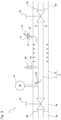
Fig. 1 is a lateral view that illustrates the general configurations of a vacuum heat insulation pipe for a liquefied gas and of a liquefied gas storage tank unit including the same according to an embodiment of the present disclosure; -
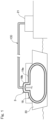
Fig. 2 is a sectional view that illustrates the vacuum heat insulation pipe for the liquefied gas ofFig. 1 on an enlarged scale; -
Fig. 3 is a sectional view that schematically illustrates the state of the pipe ofFig. 2 when a breakage happens in the inner tube; -
Fig. 4 is a sectional view that schematically illustrates the state of the pipe ofFig. 2 when a breakage happens in the outer tube; and -
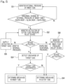
Fig. 5 is a flowchart that illustrates a breakage detection method for a pipe according to an embodiment of the present disclosure. - Hereinafter, preferred embodiments of the present disclosure are described with reference to the drawings.
Fig. 1 shows a vacuum heatinsulation piping unit 1 for a liquefied gas (hereinafter, simply referred to as a "piping unit"), and a liquefied gas storage tank unit 3 (hereinafter, simply referred to as a "tank unit") that includes such apiping unit 1 according to an embodiment of the present disclosure. Thepiping unit 1 is used to transfer a liquefied gas. Thepiping unit 1 includes a vacuum heat insulation pipe 5 (hereinafter, simply referred to as a "pipe") with a double-walled pipe structure. That is, thepipe 5 is formed of an inner tube 7 that conveys a liquefied gas therethrough and anouter tube 9 covering the inner tube 7, as shown inFig. 2 . Avacuum layer 11 defined in a radial space between the inner tube 7 and theouter tube 9. Thepiping unit 1 further includes an inner-tubepressure measuring device 13 that measures a pressure inside the inner tube 7, an outer-tubepressure relief device 15 located on theouter tube 9, and agas detector 17 that detects the type of a gas that is discharged through the outer-tubepressure relief device 15. - As depicted in
Fig. 1 , thetank unit 3 includes atank 19 that stores a liquefied gas and theaforementioned piping unit 1 which is mounted to thetank 19. Thepipe 5 of thepiping unit 1 transfers a liquefied gas between thetank 19 and a place external thereto, such as a liquefiedgas storage terminal 21 on land. Thetank unit 3 is installed in avessel 23 such as a liquefied gas carrier vessel. Nevertheless, thetank unit 3 can be installed on land. - The liquefied gas to be stored in the
tank 19 and transferred through thepipe 5 is, for example, a liquefied petroleum gas (LPG; at about -45°C), a liquefied ethylene gas (LEG; at about -100°C), a liquefied natural gas (LNG; at about -160°C), liquefied hydrogen (LH2; at about -250°C), or liquefied helium (LHe; at about -270°C). In the instant embodiment, liquefied hydrogen is to be stored in thetank 19, and this liquefied hydrogen is to be transferred through thepipe 5. - In the instant embodiment, the
tank 19 is constructed as a double-shell tank having an inner shell and an outer shell. For instance, a vacuum heat insulation layer is defined between the inner shell and the outer shell. Nevertheless, the construction of thetank 19 is not limited to this example. For instance, thetank 19 may have a vacuum heat insulation layer packed with a powder heat insulation material in the form of heat insulation granules such as perlite. Alternatively, thetank 19 may be a single-shell tank covered with a heat insulation material. The heat insulation material in this case may, for example, be formed of a plurality of vacuum heat insulation panels or be formed of a plurality of foamed panels. - To give more details, the
tank 19 in the instant embodiment has abody part 19a which is a part where a liquefied gas is to be stored and adome part 19b which projects upwards from thebody part 19a. Thepipe 5 of thepiping unit 1 is mounted to thedome part 19b. Note that, while only onepiping unit 1 is depicted in the figure for simplicity, a plurality ofpiping units 1 may be associated with asingle tank 19. Thepipe 5 is arranged to extend from the interior of thebody part 19a to the exterior of thetank 19, penetrating through thedome part 19b. In the instant embodiment, the part of thepipe 5 which is positioned to extend in the exterior of thedome part 19b is constructed as a double-walled vacuum pipe that is discussed in detail below. - In the instant embodiment, as depicted in
Fig. 2 , thepipe 5 is constructed by coupling together a plurality ofpipe segments 5a in a length direction thereof. In particular, each of thepipe segments 5a is provided, at each of opposite ends thereof, with ashield 25 that closes thevacuum layer 11 between theouter tube 9 and the inner tube 7, as shown inFig. 2 . Further, the inner tube 7 in each of thepipe segments 5a is provided with agate valve 27 in proximity to each of opposite ends thereof. Building thepipe 5 by combining thepipe segments 5a having such a structure not only facilitates the installation operation of thepipe 5 but also makes it easier to maintain and control a degree of vacuum in thevacuum layer 11. - In the instant embodiment, an outer-tube pressure relief valve - more specifically, a seal-off valve - is used as the outer-tube
pressure relief device 15. The seal-off valve serving as the outer-tubepressure relief device 15 includes acylindrical valve body 31 located on the outer peripheral surface of theouter tube 9 so as to project therefrom, and a disc-shaped valve element (not shown) fitted to the inner periphery of thevalve body 31. An O-ring is mounted to the outer peripheral surface of the valve element. In the instant example, the outer-tubepressure relief device 15 is provided for each of thepipe segments 5a. - At the outer-tube
pressure relief device 15 which is configured as a seal-off valve in the instant embodiment, the valve element is pressed against thevalve body 31 by the action of the vacuum pressure in thevacuum layer 11 during a normal operation. When, as a consequence of a breakage in thepipe 5, etc., a positive pressure prevails inside theouter tube 9, the valve element is kept in place with respect to thevalve body 31 only by a friction force between the inner peripheral surface of thevalve body 31 and the O-ring. In other words, when the pressure in thevacuum layer 11 is less than a predetermined set activation value, the valve element closes agas discharge outlet 37 in thevalve body 31 of the outer-tubepressure relief device 15. On the other hand, when the pressure in thevacuum layer 11 rises above the set activation value, the pressure forces the valve element to be detached from the inner periphery of thevalve body 31, causing the gas within thepipe 5 to be released from thegas discharge outlet 37. The set activation value for the outer-tubepressure relief device 15 is chosen to be sufficiently smaller than a maximum allowable pressure design value for the outer tube 9 (for example, the value is chosen to be approximately in the range of 1/100 to 1/10 of the maximum allowable pressure design value for the outer tube 9). Note that, at the time of installing thepipe 5, a vacuum pump is coupled to thegas discharge outlet 37 to evacuate the interior of theouter tube 9 to a vacuum via thegas discharge outlet 37. - Note that the outer-tube
pressure relief device 15 is not limited to the seal-off valve described above. Any other device may be employed as long as the device is capable of releasing gas when the predetermined set activation value is reached. Nevertheless, use of an outer-tube pressure relief valve, such as the seal-off valve on theouter tube 9 that defines thevacuum layer 11 therein, can simplify the structure of thepiping unit 1. - Furthermore, as shown in
Fig. 2 , the inner tube 7 is provided with an inner-tube pressure relief device 39 (which is, in the instant example, an inner-tube pressure relief valve). In the illustrated example, apressure relief passage 41 branches from the inner tube 7, and the inner-tubepressure relief device 39 is located in thispressure relief passage 41. For example, a springloaded safety valve is employed as the inner-tubepressure relief device 39. - In the instant embodiment, a gas detection tape configured to change color when coming into contact with a detection target gas (which is, in the instant embodiment, a hydrogen gas) is employed as the
gas detector 17. The gas detection tape is attached to thegas discharge outlet 37 of the outer-tubepressure relief device 15. - Next, a method for detecting occurrence of a breakage in the
pipe 5 of thepiping unit 1 having the above configuration and shown inFig. 2 is discussed. - To begin with, circumstances resulting from occurrence of a breakage in either one of the inner tube 7 or the
outer tube 9 are described, the circumstances being assumed in the method for detecting occurrence of a breakage in thepipe 5. The following discussions are based on the assumption that, as an example, unloading operation of a liquefied gas from thetank 19 via thepipe 5 has been completed, and an on-off valve between thetank 19 and thepipe 5 is closed (that is, the liquefied gas is not flowing through thepipe 5 but is retained inside the pipe 5). Also, in the following discussions, the gas to be stored in thetank 19 and transferred through the pipe 5 - the gas of interest for leakage detection in this breakage detection method - may sometimes be called a "detection target gas." The detection target gas may be in a liquid phase, in a gas phase, or in a mixed phase thereof. - Firstly, in a normal state where there is no breakage in either one of the inner tube 7 or the
outer tube 9, heat input to thepipe 5 from the external environment causes a gradual temperature rise in the inner tube 7 and thereby a continuous and slow pressure rise in the inner tube 7. Nevertheless, because thepipe 5 is constructed as a vacuumheat insulation pipe 5 as mentioned above, the pressure rise in the inner tube 7 in a normal state proceeds at a very slow rate. - If, in this normal state, a relatively large breakage occurs in the inner tube 7 as shown in
Fig. 3 , the detection target gas G leaks at the breakage site into thevacuum layer 11 within theouter tube 9. Then, due to the pressure difference between the interior of the inner tube 7 and thevacuum layer 11, the internal pressure of the inner tube 7 drops rapidly. - When the detection target gas G leaks into the
vacuum layer 11, heat insulation performance of thevacuum layer 11 is deteriorated, so that the detection target gas G undergoes a temperature rise and evaporates due to heat input from the external environment. Thus, the pressure inside the inner tube 7, which has once been dropped, is increased again. Along with this pressure rise inside the inner tube 7, the detection target gas G further leaks into the interior of theouter tube 9, raising the pressure inside theouter tube 9 as well. - In contrast, when a small breakage occurs in the inner tube 7, the pressure inside the inner tube 7 is slowly decreased initially after the occurrence of the breakage, due to the detection target gas G leaking from the inner tube 7. Then, the internal pressure of the inner tube 7 is slowly increased as a result of degradation of heat insulation performance of the
vacuum layer 11. The temperature of the inner tube 7 also rises due to degradation of heat insulation performance of thevacuum layer 11, so that the detection target gas G escaping into thevacuum layer 11 expands to increase the pressure inside theouter tube 9. - When the pressure inside the
outer tube 9 reaches the set activation value for the outer-tubepressure relief device 15, the outer-tubepressure relief device 15 is activated to discharge the detection target gas G. In this process, the gas detector 17 (i.e., gas detection tape) attached to thegas discharge outlet 37 of the outer-tubepressure relief device 15 responds to the detection target gas G and changes color, providing a status that is able to indicate discharge of the detection target gas G. - Next, circumstances resulting from occurrence of a breakage in the
outer tube 9 and consequential leakage of a liquefied gas from theouter tube 9 are described. - When a breakage occurs in the
outer tube 9, and air A flows into thevacuum layer 11 from the external environment as shown inFig. 4 , heat insulation performance of thevacuum layer 11 is deteriorated, so that the detection target gas G undergoes a temperature rise and evaporates due to heat input from the external environment. Thus, the pressure inside the inner tube 7 is rapidly increased. - Where the breakage in the
outer tube 9 is small in magnitude, and a small amount of air A flows into thevacuum layer 11 from the external environment, the air A that has flown into thevacuum layer 11 is cooled by the inner tube 7 having a low temperature and thereby condensates onto the surface of the inner tube 7 as liquefied air A. Thereafter, as the air A further flows in, the temperature on the surface of the inner tube 7 and in the vacuum layer rises, causing the once liquefied air A to evaporate. Through such inflow of the air A from the external environment and evaporation of the liquefied air A, the pressure in thevacuum layer 11, or inside theouter tube 9, is increased. - When the pressure inside the
outer tube 9 reaches the set activation value for the outer-tubepressure relief device 15, the outer-tubepressure relief device 15 is activated to discharge the air A. In this process, the gas detector 17 (i.e., gas detection tape) attached to thegas discharge outlet 37 of the outer-tubepressure relief device 15 does not respond to the air A, providing a status that is able to indicate no discharge of the detection target gas G. - Where the breakage in the
outer tube 9 is large in magnitude, and a huge amount of air A flows into thevacuum layer 11 from the external environment upon the occurrence of the breakage, one of the possible scenarios may be that the pressure inside theouter tube 9 does not reach the set activation value for the outer-tubepressure relief device 15 while the inner tube 7 experiences a rapid and substantial rise in the internal pressure as a result of substantial deterioration in the vacuum degree as well as the temperature rise in the inner tube 7. In this case, only the inner-tubepressure relief device 39 is activated, but the outer-tubepressure relief device 15 is not activated. - In view of the abovementioned circumstances triggered by occurrence of a breakage in the inner tube 7 or the
outer tube 9, a breakage detection method for apipe 5 according to the present embodiment includes, as illustrated inFig. 5 , monitoring a pressure inside the inner tube 7 by using the inner-tube pressure measuring device 13 (i.e., an inner-tube internal pressure monitoring step S1); when an abnormal change is detected in measurements taken by the inner-tubepressure measuring device 13, monitoring whether the outer-tubepressure relief device 15 is activated within a selected time period (i.e., an outer-tube pressure relief device activation monitoring step S2); when the outer-tubepressure relief device 15 is activated, detecting whether the detection target gas is discharged by using the gas detector 17 (i.e., a target-gas discharge detecting step S3); and determining occurrence of a breakage in the inner tube 7 or in theouter tube 9 on the basis of the measurements taken by the inner-tubepressure measuring device 13 and the type of the discharged gas as indicated by thegas detector 17, (i.e., a breakage occurrence determining step S4). - The term "abnormal change" in measurements taken by the inner-tube
pressure measuring device 13 herein means a change behavior distinct from that of a continuous and slow rise in the pressure inside the inner tube 7 during a normal state that is discussed earlier. More specifically, typical examples of "abnormal change" include a rapid change (or drop) in the pressure inside the inner tube 7 resulting from occurrence of a relatively large breakage in the inner tube 7; a slow drop in the pressure inside the inner tube 7 resulting from occurrence of a small breakage in the inner tube 7; and a rapid change (or rise) in the pressure inside the inner tube 7 resulting from occurrence of a breakage in theouter tube 9 as mentioned above. - In particular, when a drop (i.e., a rapid drop or a slow drop) in the measurements is detected at the inner-tube internal pressure monitoring step S1, it may be subsequently confirmed that the outer-tube
pressure relief device 15 is activated at the outer-tube pressure relief device activation monitoring step S2. Then, if discharge of the detection target gas G (which is, in the instant example, a hydrogen gas) is detected at the step S3 by means of the gas detector 17 (which is, in the instant example, a gas detection tape attached to thegas discharge outlet 37 of the outer-tube pressure relief device 15), it is determined that a breakage has occurred in the inner tube 7 at the breakage occurrence determining step S4. - Meanwhile, when a rapid rise in the measurements is detected at the inner-tube internal pressure monitoring step S1, it may be subsequently confirmed that the outer-tube
pressure relief device 15 is activated at the outer-tube pressure relief device activation monitoring step S2. Then, by confirming that there has been no discharge of the detection target gas G by means of thegas detector 17, it is determined that a breakage has occurred in theouter tube 9 at the breakage occurrence determining step S4. - What behavior of a pressure change is to be identified as "abnormal" (e.g., what rate of pressure drop or pressure rise is to be defined as "slow" or "rapid") at the inner-tube internal pressure monitoring step S1 is set as appropriate through experiments and calculations conducted in advance, based on the type of the detection target gas G, the size of the
pipe 5, the size of thetank 19, the amount of the gas stored, etc. Likewise, for what time period a valve is monitored for activation at the outer-tube pressure relief device activation monitoring step S2 is also set as appropriate through experiments and calculations conducted in advance. - Even when occurrence of a breakage in the inner tube 7 has brought about an abnormal change (which is, in the instant example, a rapid drop or a slow drop) in the pressure inside the inner tube 7, in some cases, the pressure inside the
outer tube 9 may not exhibit a sufficient rise to trigger the activation of the outer-tubepressure relief device 15. Such a situation tends to arise, for example, when a tiny breakage has occurred in the inner tube 7. To address such a situation, the method may additionally include a step of supplying the detection target gas G from an external source into the inner tube 7 (i.e., a detection target gas supplying step S5) in the event that, while it is detected at the inner-tube internal pressure monitoring step S1 that an abnormal change has occurred in the measurements taken by the inner-tubepressure measuring device 13, an activation of the outer-tubepressure relief device 15 is not subsequently confirmed within the predefined, selected time period at the outer-tube pressure relief device activation monitoring step S2. In such a case, the outer-tube pressure relief device activation monitoring step S2 is performed again after the detection target gas G supplying step. If it is confirmed that the outer-tubepressure relief device 15 is activated, and if discharge of the detection target gas G is detected by means of thegas detector 17, it is determined that a breakage has occurred in the inner tube 7. - Note that regardless of whether there has or has not been an abnormal change in the pressure inside the inner tube 7, the detection target gas G may be supplied from an external source into the inner tube 7 if an activation of the outer-tube
pressure relief device 15 is not confirmed within the predefined, selected time period. - In particular, the supplying of the detection target gas G can be performed, for example, by applying cool-down that is provided for a loading and/or unloading operation. Also, in case of a large-sized liquefied gas carrier vessel equipped with a cool-down system, the supplying of the gas may even be performed during operation of the vessel by making use of the cool-down system.
- Meanwhile, as described above, when the breakage in the
outer tube 9 is large in magnitude, one of the possible scenarios may be that the pressure inside theouter tube 9 does not reach the set activation value for the outer-tubepressure relief device 15 while the inner tube 7 experiences a rapid and substantial rise in the internal pressure, ending up with the outer-tubepressure relief device 15 not being activated. To address such a situation, the method may additionally include a step of monitoring whether the inner-tubepressure relief device 39 is activated (i.e., an inner-tube pressure relief device activation monitoring step S6) in the event that, while it is detected at the inner-tube internal pressure monitoring step S1 that a rapid rise has occurred in the measurements taken by the inner-tubepressure measuring device 13, an activation of the outer-tubepressure relief device 15 is not subsequently confirmed at the outer-tube pressure relief device activation monitoring step S2. In such a case, if activation of the inner-tubepressure relief device 39 is confirmed, it is determined that a breakage has occurred in theouter tube 9. - Note that detection of discharge of the detection target gas G at the target-gas discharge detecting step S3 may be performed by using a
different gas detector 17 in place of the gas detection tape attached to thegas discharge outlet 37 of the outer-tubepressure relief device 15. For example, a portable gas detector may be brought close to thegas discharge outlet 37 by a person responsible for the management of thepipe 5, for direct measurement in order to detect discharge of the detection target gas G. - Note that, when discharge of the detection target gas G is not detected at the target-gas discharge detecting step S3 despite the fact that a drop in the internal pressure has been detected at the inner-tube internal pressure monitoring step S1, other causes may be suspected such as leakage via a gate valve or
gate valves 27 at the inner tube 7, instead of a breakage in the inner tube 7. Hence, relevant sites including such gate valve(s) 27 should be inspected. - According to a vacuum heat
insulation piping unit 1 for a liquefied gas, a storage tank unit, and a breakage detection method in accordance with the embodiment as discussed thus far, it is possible to find out when the outer-tubepressure relief device 15 is highly likely to be actuated before actual actuation by relying on measurement of a pressure inside the inner tube 7 of thepipe 5 with a double-walled vacuum structure and, moreover, to detect a breakage in thepipe 5 with a simple design and in a timely and reliable manner because the type of a gas discharged through the outer-tubepressure relief device 15 is detected in combination with the pressure measurement. - Although the present disclosure has been described in terms of the preferred embodiments thereof with reference to the drawings, various additions, modifications, or omissions may be made without departing from the scope of the present disclosure. Accordingly, such variants are included within the scope of the present disclosure.
-
- 1
- piping unit
- 3
- liquefied gas storage tank unit
- 5
- vacuum heat insulation pipe
- 7
- inner tube
- 9
- outer tube
- 11
- vacuum layer
- 13
- inner-tube pressure measuring device
- 15
- outer-tube pressure relief valve
- 17
- gas detector
- 19
- tank
Claims (7)
- A vacuum heat insulation piping unit for a liquefied gas, the piping unit being configured to transfer the liquefied gas and comprising:a vacuum heat insulation pipe including an inner tube configured to convey the liquefied gas therethrough and an outer tube covering the inner tube with a vacuum layer defined between the inner tube and the outer tube;an inner-tube pressure measuring device configured to measure a pressure inside the inner tube;an outer-tube pressure relief device located on the outer tube; anda gas detector configured to detect the type of a gas that is discharged through the outer-tube pressure relief device.
- The vacuum heat insulation piping unit for the liquefied gas as claimed in claim 1, wherein the outer-tube pressure relief device comprises an outer-tube pressure relief valve, and
the gas detector comprises a gas detection tape attached to a gas discharge outlet of the outer-tube pressure relief valve. - A liquefied gas storage tank unit comprising:a tank configured to store a liquefied gas; anda vacuum heat insulation piping unit for the liquefied gas as claimed in claim 1 or 2, the piping unit being mounted to the tank and being configured to transfer the liquefied gas between the tank and a place external thereto.
- A method for detecting occurrence of a breakage in a vacuum heat insulation pipe for transferring a liquefied gas, the vacuum heat insulation pipe including an inner tube configured to convey the liquefied gas therethrough and an outer tube covering the inner tube with a vacuum layer defined between the inner tube and the outer tube, the method comprising:monitoring a pressure inside the inner tube by using an inner-tube pressure measuring device configured to measure the pressure inside the inner tube;when an abnormal change is detected in measurements taken by the inner-tube pressure measuring device, monitoring whether an outer-tube pressure relief device located on the outer tube is actuated within a selected time period;when the outer-tube pressure relief device is activated, detecting whether a detection target gas is discharged by using a gas detector; anddetermining occurrence of a breakage in the inner tube or in the outer tube on the basis of the measurements taken by the inner-tube pressure measuring device and the presence or absence of discharge of the detection target gas as indicated by the gas detector.
- The method as claimed in claim 4, comprisingin the monitoring of the pressure inside the inner tube, detecting the abnormal change in the form of a drop in the measurements taken by the inner-tube pressure measuring device,upon detection of the drop in the measurements taken by the inner-tube pressure measuring device, monitoring whether the outer-tube pressure relief device is activated within the selected time period, andwhen the outer-tube pressure relief device is activated, detecting discharge of the detection target gas by using the gas detector to determine occurrence of a breakage in the inner tube.
- The method as claimed in claim 5, comprisingwhen the outer-tube pressure relief device is not activated within the selected time period after detection of the drop in the measurements taken by the inner-tube pressure measuring device, supplying the detection target gas from an external source into the inner tube,upon supplying the detection target gas into the inner tube, monitoring whether the outer-tube pressure relief device is activated within the selected time period, andwhen the outer-tube pressure relief device is activated, detecting discharge of the detection target gas by using the gas detector to determine occurrence of a breakage in the inner tube.
- The method as claimed in claim 4, comprisingin the monitoring of the pressure inside the inner tube, detecting the abnormal change in the form of a rapid rise in the measurements taken by the inner-tube pressure measuring device,upon detection of the rapid rise in the measurements taken by the inner-tube pressure measuring device, monitoring whether the outer-tube pressure relief device is activated within the selected time period, andwhen the outer-tube pressure relief device is activated, confirming that there has been no discharge of the detection target gas by using the gas detector to determine occurrence of a breakage in the outer tube.
Applications Claiming Priority (2)
| Application Number | Priority Date | Filing Date | Title |
|---|---|---|---|
| JP2020215771A JP7623136B2 (en) | 2020-12-24 | 2020-12-24 | Vacuum insulated piping unit for liquefied gas and method for detecting damage to vacuum insulated piping for liquefied gas |
| PCT/JP2021/047285 WO2022138628A1 (en) | 2020-12-24 | 2021-12-21 | Vacuum insulated pipe unit for liquefied gas and method for detecting damage in vacuum insulated pipe for liquefied gas |
Publications (3)
| Publication Number | Publication Date |
|---|---|
| EP4269862A1 true EP4269862A1 (en) | 2023-11-01 |
| EP4269862A4 EP4269862A4 (en) | 2024-11-06 |
| EP4269862B1 EP4269862B1 (en) | 2025-11-12 |
Family
ID=82159384
Family Applications (1)
| Application Number | Title | Priority Date | Filing Date |
|---|---|---|---|
| EP21910771.1A Active EP4269862B1 (en) | 2020-12-24 | 2021-12-21 | Vacuum insulated pipe unit for liquefied gas and method for detecting damage in vacuum insulated pipe for liquefied gas |
Country Status (5)
| Country | Link |
|---|---|
| EP (1) | EP4269862B1 (en) |
| JP (1) | JP7623136B2 (en) |
| KR (1) | KR102975632B1 (en) |
| CN (1) | CN116635664A (en) |
| WO (1) | WO2022138628A1 (en) |
Families Citing this family (4)
| Publication number | Priority date | Publication date | Assignee | Title |
|---|---|---|---|---|
| KR20250028411A (en) | 2022-10-12 | 2025-02-28 | 카와사키 주코교 카부시키 카이샤 | Piping unit for transporting cryogenic fluids |
| WO2024127451A1 (en) * | 2022-12-12 | 2024-06-20 | 川崎重工業株式会社 | Piping equipment and piping equipment control method |
| JP2025088539A (en) | 2023-11-30 | 2025-06-11 | 川崎重工業株式会社 | Liquefied gas piping unit and method for assembling same |
| CN119873713B (en) * | 2025-02-12 | 2026-02-24 | 湖北弘仪智能装备有限责任公司 | Liquid hazardous chemical substance loading and unloading controller and loading and unloading control method thereof |
Family Cites Families (15)
| Publication number | Priority date | Publication date | Assignee | Title |
|---|---|---|---|---|
| JP2561667Y2 (en) | 1991-10-14 | 1998-02-04 | 石川島播磨重工業株式会社 | Inert gas replacement device in loading arm for receiving liquefied gas |
| DE4232195C1 (en) * | 1992-09-25 | 1993-06-24 | Man Nutzfahrzeuge Ag, 8000 Muenchen, De | |
| JP2000146376A (en) * | 1998-11-05 | 2000-05-26 | Hitachi Ltd | Refrigerator |
| JP2001349499A (en) | 2000-06-02 | 2001-12-21 | Ishikawajima Harima Heavy Ind Co Ltd | Cryogenic tank |
| JP2009217695A (en) | 2008-03-12 | 2009-09-24 | Taiyo Nippon Sanso Corp | Gas detecting device |
| JP5301254B2 (en) | 2008-12-02 | 2013-09-25 | 理研計器株式会社 | Optical gas detector |
| JP6134211B2 (en) | 2013-06-19 | 2017-05-24 | 川崎重工業株式会社 | Double shell tank and liquefied gas carrier |
| JP6418680B2 (en) | 2014-09-30 | 2018-11-07 | 川崎重工業株式会社 | Liquid hydrogen transfer system |
| JP2017020914A (en) * | 2015-07-10 | 2017-01-26 | 川崎重工業株式会社 | Method and apparatus for determining the life of a double pipe for liquefied hydrogen |
| JP6545023B2 (en) | 2015-07-15 | 2019-07-17 | 川崎重工業株式会社 | Liquid hydrogen loading arm and liquid hydrogen transfer method |
| WO2017214031A1 (en) * | 2016-06-06 | 2017-12-14 | Hexagon Technology As | Inline cycle fuse |
| JP6734724B2 (en) * | 2016-07-29 | 2020-08-05 | 芝浦メカトロニクス株式会社 | Damage detection device for double container, damage detection method, and substrate processing device |
| CN109458500A (en) * | 2018-11-22 | 2019-03-12 | 亚达管道系统股份有限公司 | Continuous vacuum is insulated double-wall pipe |
| US11035515B2 (en) * | 2018-12-20 | 2021-06-15 | The Boeing Company | Conduits for transporting fluids |
| CN211399350U (en) * | 2019-12-11 | 2020-09-01 | 广东电网有限责任公司 | A superconducting cable low temperature pipeline leak detection device |
-
2020
- 2020-12-24 JP JP2020215771A patent/JP7623136B2/en active Active
-
2021
- 2021-12-21 CN CN202180086086.2A patent/CN116635664A/en active Pending
- 2021-12-21 WO PCT/JP2021/047285 patent/WO2022138628A1/en not_active Ceased
- 2021-12-21 EP EP21910771.1A patent/EP4269862B1/en active Active
- 2021-12-21 KR KR1020237021251A patent/KR102975632B1/en active Active
Also Published As
| Publication number | Publication date |
|---|---|
| WO2022138628A1 (en) | 2022-06-30 |
| KR102975632B1 (en) | 2026-06-09 |
| JP7623136B2 (en) | 2025-01-28 |
| KR20230104987A (en) | 2023-07-11 |
| CN116635664A (en) | 2023-08-22 |
| JP2022101284A (en) | 2022-07-06 |
| EP4269862B1 (en) | 2025-11-12 |
| EP4269862A4 (en) | 2024-11-06 |
Similar Documents
| Publication | Publication Date | Title |
|---|---|---|
| EP4269862B1 (en) | Vacuum insulated pipe unit for liquefied gas and method for detecting damage in vacuum insulated pipe for liquefied gas | |
| EP3012510B1 (en) | Liquefied gas-storing tank and liquefied gas transport vessel | |
| JP7141536B2 (en) | How to detect leaks in sealed insulated tanks | |
| US11525738B2 (en) | Device and method for determining the thermal insulation quality of twin-walled, vacuum-insulated containers | |
| US11293828B2 (en) | Inline cycle fuse | |
| US12117129B2 (en) | Method for checking the leakproofness of a leakproof and thermally insulating tank for storing a fluid | |
| KR101751841B1 (en) | Leakage Liquefied Gas of Storage Tank Treatment System and Method | |
| KR20150120733A (en) | Apparatus and method for leak detection of liquified gas | |
| WO2010003353A1 (en) | Leakage self-help container for stocking hazardous chemical products | |
| JP4576939B2 (en) | Apparatus and method for monitoring vacuum reduction of vacuum insulation structure | |
| KR20230147308A (en) | Insulation performance evaluation equipment and method | |
| KR101551789B1 (en) | Leakage locator for stand-alone storage tank | |
| JP5688324B2 (en) | Dew point temperature adjustment system for loading arm | |
| JPH028200B2 (en) | ||
| US12038132B2 (en) | Method for detecting leaks in a pressurised gas tank head and tank head for use of such a method | |
| JP5733265B2 (en) | Gas filling device, gas tank inspection device, and gas tank inspection method | |
| US20250043913A1 (en) | Storage tank | |
| US20250043924A1 (en) | Storage tank | |
| US12618528B2 (en) | Pressure accumulator | |
| US20250043912A1 (en) | Storage tank | |
| JP2007191172A (en) | Double shell tank system | |
| Kumar et al. | Liquid nitrogen storage and distribution system for 6.5-meter large thermal vacuum chamber-LTVC | |
| CA3049601C (en) | Device and method for determining the heat insulation quality of dual-wall, vacuum-insulated containers | |
| KR20240116142A (en) | Cryogenic impact test system | |
| BR102024013906A2 (en) | STORAGE TANK, AIRCRAFT, AND METHOD FOR INSPECTING A STORAGE TANK |
Legal Events
| Date | Code | Title | Description |
|---|---|---|---|
| STAA | Information on the status of an ep patent application or granted ep patent |
Free format text: STATUS: THE INTERNATIONAL PUBLICATION HAS BEEN MADE |
|
| PUAI | Public reference made under article 153(3) epc to a published international application that has entered the european phase |
Free format text: ORIGINAL CODE: 0009012 |
|
| STAA | Information on the status of an ep patent application or granted ep patent |
Free format text: STATUS: REQUEST FOR EXAMINATION WAS MADE |
|
| 17P | Request for examination filed |
Effective date: 20230704 |
|
| AK | Designated contracting states |
Kind code of ref document: A1 Designated state(s): AL AT BE BG CH CY CZ DE DK EE ES FI FR GB GR HR HU IE IS IT LI LT LU LV MC MK MT NL NO PL PT RO RS SE SI SK SM TR |
|
| DAV | Request for validation of the european patent (deleted) | ||
| DAX | Request for extension of the european patent (deleted) | ||
| A4 | Supplementary search report drawn up and despatched |
Effective date: 20241004 |
|
| RIC1 | Information provided on ipc code assigned before grant |
Ipc: F16L 9/18 20060101ALI20240927BHEP Ipc: F16L 59/065 20060101ALI20240927BHEP Ipc: F16L 55/00 20060101ALI20240927BHEP Ipc: G01M 3/28 20060101ALI20240927BHEP Ipc: G01M 3/20 20060101ALI20240927BHEP Ipc: F17D 5/02 20060101ALI20240927BHEP Ipc: F17C 13/00 20060101AFI20240927BHEP |
|
| GRAP | Despatch of communication of intention to grant a patent |
Free format text: ORIGINAL CODE: EPIDOSNIGR1 |
|
| STAA | Information on the status of an ep patent application or granted ep patent |
Free format text: STATUS: GRANT OF PATENT IS INTENDED |
|
| INTG | Intention to grant announced |
Effective date: 20250721 |
|
| GRAS | Grant fee paid |
Free format text: ORIGINAL CODE: EPIDOSNIGR3 |
|
| GRAA | (expected) grant |
Free format text: ORIGINAL CODE: 0009210 |
|
| STAA | Information on the status of an ep patent application or granted ep patent |
Free format text: STATUS: THE PATENT HAS BEEN GRANTED |
|
| AK | Designated contracting states |
Kind code of ref document: B1 Designated state(s): AL AT BE BG CH CY CZ DE DK EE ES FI FR GB GR HR HU IE IS IT LI LT LU LV MC MK MT NL NO PL PT RO RS SE SI SK SM TR |
|
| REG | Reference to a national code |
Ref country code: CH Ref legal event code: F10 Free format text: ST27 STATUS EVENT CODE: U-0-0-F10-F00 (AS PROVIDED BY THE NATIONAL OFFICE) Effective date: 20251112 Ref country code: GB Ref legal event code: FG4D |
|
| REG | Reference to a national code |
Ref country code: DE Ref legal event code: R096 Ref document number: 602021042447 Country of ref document: DE |
|
| REG | Reference to a national code |
Ref country code: IE Ref legal event code: FG4D |
|
| PGFP | Annual fee paid to national office [announced via postgrant information from national office to epo] |
Ref country code: NO Payment date: 20251231 Year of fee payment: 5 |
|
| PGFP | Annual fee paid to national office [announced via postgrant information from national office to epo] |
Ref country code: AT Payment date: 20260113 Year of fee payment: 5 |
|
| REG | Reference to a national code |
Ref country code: NL Ref legal event code: MP Effective date: 20251112 |
|
| PG25 | Lapsed in a contracting state [announced via postgrant information from national office to epo] |
Ref country code: ES Free format text: LAPSE BECAUSE OF FAILURE TO SUBMIT A TRANSLATION OF THE DESCRIPTION OR TO PAY THE FEE WITHIN THE PRESCRIBED TIME-LIMIT Effective date: 20251112 |
|
| REG | Reference to a national code |
Ref country code: LT Ref legal event code: MG9D |
|
| PG25 | Lapsed in a contracting state [announced via postgrant information from national office to epo] |
Ref country code: HR Free format text: LAPSE BECAUSE OF FAILURE TO SUBMIT A TRANSLATION OF THE DESCRIPTION OR TO PAY THE FEE WITHIN THE PRESCRIBED TIME-LIMIT Effective date: 20251112 Ref country code: AT Free format text: LAPSE BECAUSE OF FAILURE TO SUBMIT A TRANSLATION OF THE DESCRIPTION OR TO PAY THE FEE WITHIN THE PRESCRIBED TIME-LIMIT Effective date: 20251112 Ref country code: FI Free format text: LAPSE BECAUSE OF FAILURE TO SUBMIT A TRANSLATION OF THE DESCRIPTION OR TO PAY THE FEE WITHIN THE PRESCRIBED TIME-LIMIT Effective date: 20251112 |
|
| REG | Reference to a national code |
Ref country code: AT Ref legal event code: MK05 Ref document number: 1856993 Country of ref document: AT Kind code of ref document: T Effective date: 20251112 |
|
| PG25 | Lapsed in a contracting state [announced via postgrant information from national office to epo] |
Ref country code: NL Free format text: LAPSE BECAUSE OF FAILURE TO SUBMIT A TRANSLATION OF THE DESCRIPTION OR TO PAY THE FEE WITHIN THE PRESCRIBED TIME-LIMIT Effective date: 20251112 |
|
| PG25 | Lapsed in a contracting state [announced via postgrant information from national office to epo] |
Ref country code: RS Free format text: LAPSE BECAUSE OF FAILURE TO SUBMIT A TRANSLATION OF THE DESCRIPTION OR TO PAY THE FEE WITHIN THE PRESCRIBED TIME-LIMIT Effective date: 20260212 |
|
| PG25 | Lapsed in a contracting state [announced via postgrant information from national office to epo] |
Ref country code: IS Free format text: LAPSE BECAUSE OF FAILURE TO SUBMIT A TRANSLATION OF THE DESCRIPTION OR TO PAY THE FEE WITHIN THE PRESCRIBED TIME-LIMIT Effective date: 20260312 |
|
| PG25 | Lapsed in a contracting state [announced via postgrant information from national office to epo] |
Ref country code: PT Free format text: LAPSE BECAUSE OF FAILURE TO SUBMIT A TRANSLATION OF THE DESCRIPTION OR TO PAY THE FEE WITHIN THE PRESCRIBED TIME-LIMIT Effective date: 20260312 |
|
| PG25 | Lapsed in a contracting state [announced via postgrant information from national office to epo] |
Ref country code: PL Free format text: LAPSE BECAUSE OF FAILURE TO SUBMIT A TRANSLATION OF THE DESCRIPTION OR TO PAY THE FEE WITHIN THE PRESCRIBED TIME-LIMIT Effective date: 20251112 |
|
| PG25 | Lapsed in a contracting state [announced via postgrant information from national office to epo] |
Ref country code: LV Free format text: LAPSE BECAUSE OF FAILURE TO SUBMIT A TRANSLATION OF THE DESCRIPTION OR TO PAY THE FEE WITHIN THE PRESCRIBED TIME-LIMIT Effective date: 20251112 |
|
| PG25 | Lapsed in a contracting state [announced via postgrant information from national office to epo] |
Ref country code: BG Free format text: LAPSE BECAUSE OF FAILURE TO SUBMIT A TRANSLATION OF THE DESCRIPTION OR TO PAY THE FEE WITHIN THE PRESCRIBED TIME-LIMIT Effective date: 20251112 |
|
| PG25 | Lapsed in a contracting state [announced via postgrant information from national office to epo] |
Ref country code: RO Free format text: LAPSE BECAUSE OF FAILURE TO SUBMIT A TRANSLATION OF THE DESCRIPTION OR TO PAY THE FEE WITHIN THE PRESCRIBED TIME-LIMIT Effective date: 20251112 |
|
| PG25 | Lapsed in a contracting state [announced via postgrant information from national office to epo] |
Ref country code: LT Free format text: LAPSE BECAUSE OF FAILURE TO SUBMIT A TRANSLATION OF THE DESCRIPTION OR TO PAY THE FEE WITHIN THE PRESCRIBED TIME-LIMIT Effective date: 20251112 |
|
| REG | Reference to a national code |
Ref country code: DE Ref legal event code: R119 Ref document number: 602021042447 Country of ref document: DE |
|
| PG25 | Lapsed in a contracting state [announced via postgrant information from national office to epo] |
Ref country code: SM Free format text: LAPSE BECAUSE OF FAILURE TO SUBMIT A TRANSLATION OF THE DESCRIPTION OR TO PAY THE FEE WITHIN THE PRESCRIBED TIME-LIMIT Effective date: 20251112 |
|
| PG25 | Lapsed in a contracting state [announced via postgrant information from national office to epo] |
Ref country code: DK Free format text: LAPSE BECAUSE OF FAILURE TO SUBMIT A TRANSLATION OF THE DESCRIPTION OR TO PAY THE FEE WITHIN THE PRESCRIBED TIME-LIMIT Effective date: 20251112 |
|
| PG25 | Lapsed in a contracting state [announced via postgrant information from national office to epo] |
Ref country code: IT Free format text: LAPSE BECAUSE OF FAILURE TO SUBMIT A TRANSLATION OF THE DESCRIPTION OR TO PAY THE FEE WITHIN THE PRESCRIBED TIME-LIMIT Effective date: 20251112 |
|
| PG25 | Lapsed in a contracting state [announced via postgrant information from national office to epo] |
Ref country code: EE Free format text: LAPSE BECAUSE OF FAILURE TO SUBMIT A TRANSLATION OF THE DESCRIPTION OR TO PAY THE FEE WITHIN THE PRESCRIBED TIME-LIMIT Effective date: 20251112 |
|
| PG25 | Lapsed in a contracting state [announced via postgrant information from national office to epo] |
Ref country code: CZ Free format text: LAPSE BECAUSE OF FAILURE TO SUBMIT A TRANSLATION OF THE DESCRIPTION OR TO PAY THE FEE WITHIN THE PRESCRIBED TIME-LIMIT Effective date: 20251112 |
|
| REG | Reference to a national code |
Ref country code: CH Ref legal event code: H13 Free format text: ST27 STATUS EVENT CODE: U-0-0-H10-H13 (AS PROVIDED BY THE NATIONAL OFFICE) Effective date: 20260723 |
|
| PG25 | Lapsed in a contracting state [announced via postgrant information from national office to epo] |
Ref country code: SK Free format text: LAPSE BECAUSE OF FAILURE TO SUBMIT A TRANSLATION OF THE DESCRIPTION OR TO PAY THE FEE WITHIN THE PRESCRIBED TIME-LIMIT Effective date: 20251112 |
|
| PG25 | Lapsed in a contracting state [announced via postgrant information from national office to epo] |
Ref country code: SE Free format text: LAPSE BECAUSE OF FAILURE TO SUBMIT A TRANSLATION OF THE DESCRIPTION OR TO PAY THE FEE WITHIN THE PRESCRIBED TIME-LIMIT Effective date: 20251112 |
|
| PG25 | Lapsed in a contracting state [announced via postgrant information from national office to epo] |
Ref country code: MC Free format text: LAPSE BECAUSE OF FAILURE TO SUBMIT A TRANSLATION OF THE DESCRIPTION OR TO PAY THE FEE WITHIN THE PRESCRIBED TIME-LIMIT Effective date: 20251112 |