EP4269793A1 - Gas compressor - Google Patents
Gas compressor Download PDFInfo
- Publication number
- EP4269793A1 EP4269793A1 EP23169828.3A EP23169828A EP4269793A1 EP 4269793 A1 EP4269793 A1 EP 4269793A1 EP 23169828 A EP23169828 A EP 23169828A EP 4269793 A1 EP4269793 A1 EP 4269793A1
- Authority
- EP
- European Patent Office
- Prior art keywords
- air vent
- air
- protective
- gas compressor
- compressor according
- Prior art date
- Legal status (The legal status is an assumption and is not a legal conclusion. Google has not performed a legal analysis and makes no representation as to the accuracy of the status listed.)
- Withdrawn
Links
Images




Classifications
-
- F—MECHANICAL ENGINEERING; LIGHTING; HEATING; WEAPONS; BLASTING
- F04—POSITIVE - DISPLACEMENT MACHINES FOR LIQUIDS; PUMPS FOR LIQUIDS OR ELASTIC FLUIDS
- F04B—POSITIVE-DISPLACEMENT MACHINES FOR LIQUIDS; PUMPS
- F04B39/00—Component parts, details, or accessories, of pumps or pumping systems specially adapted for elastic fluids, not otherwise provided for in, or of interest apart from, groups F04B25/00 - F04B37/00
- F04B39/12—Casings; Cylinders; Cylinder heads; Fluid connections
- F04B39/121—Casings
-
- F—MECHANICAL ENGINEERING; LIGHTING; HEATING; WEAPONS; BLASTING
- F04—POSITIVE - DISPLACEMENT MACHINES FOR LIQUIDS; PUMPS FOR LIQUIDS OR ELASTIC FLUIDS
- F04B—POSITIVE-DISPLACEMENT MACHINES FOR LIQUIDS; PUMPS
- F04B35/00—Piston pumps specially adapted for elastic fluids and characterised by the driving means to their working members, or by combination with, or adaptation to, specific driving engines or motors, not otherwise provided for
- F04B35/04—Piston pumps specially adapted for elastic fluids and characterised by the driving means to their working members, or by combination with, or adaptation to, specific driving engines or motors, not otherwise provided for the means being electric
-
- F—MECHANICAL ENGINEERING; LIGHTING; HEATING; WEAPONS; BLASTING
- F04—POSITIVE - DISPLACEMENT MACHINES FOR LIQUIDS; PUMPS FOR LIQUIDS OR ELASTIC FLUIDS
- F04B—POSITIVE-DISPLACEMENT MACHINES FOR LIQUIDS; PUMPS
- F04B35/00—Piston pumps specially adapted for elastic fluids and characterised by the driving means to their working members, or by combination with, or adaptation to, specific driving engines or motors, not otherwise provided for
- F04B35/06—Mobile combinations
-
- F—MECHANICAL ENGINEERING; LIGHTING; HEATING; WEAPONS; BLASTING
- F04—POSITIVE - DISPLACEMENT MACHINES FOR LIQUIDS; PUMPS FOR LIQUIDS OR ELASTIC FLUIDS
- F04B—POSITIVE-DISPLACEMENT MACHINES FOR LIQUIDS; PUMPS
- F04B39/00—Component parts, details, or accessories, of pumps or pumping systems specially adapted for elastic fluids, not otherwise provided for in, or of interest apart from, groups F04B25/00 - F04B37/00
- F04B39/06—Cooling; Heating; Prevention of freezing
- F04B39/066—Cooling by ventilation
-
- F—MECHANICAL ENGINEERING; LIGHTING; HEATING; WEAPONS; BLASTING
- F04—POSITIVE - DISPLACEMENT MACHINES FOR LIQUIDS; PUMPS FOR LIQUIDS OR ELASTIC FLUIDS
- F04B—POSITIVE-DISPLACEMENT MACHINES FOR LIQUIDS; PUMPS
- F04B27/00—Multi-cylinder pumps specially adapted for elastic fluids and characterised by number or arrangement of cylinders
- F04B27/005—Multi-cylinder pumps specially adapted for elastic fluids and characterised by number or arrangement of cylinders with two cylinders
-
- F—MECHANICAL ENGINEERING; LIGHTING; HEATING; WEAPONS; BLASTING
- F04—POSITIVE - DISPLACEMENT MACHINES FOR LIQUIDS; PUMPS FOR LIQUIDS OR ELASTIC FLUIDS
- F04B—POSITIVE-DISPLACEMENT MACHINES FOR LIQUIDS; PUMPS
- F04B41/00—Pumping installations or systems specially adapted for elastic fluids
- F04B41/02—Pumping installations or systems specially adapted for elastic fluids having reservoirs
-
- F—MECHANICAL ENGINEERING; LIGHTING; HEATING; WEAPONS; BLASTING
- F04—POSITIVE - DISPLACEMENT MACHINES FOR LIQUIDS; PUMPS FOR LIQUIDS OR ELASTIC FLUIDS
- F04B—POSITIVE-DISPLACEMENT MACHINES FOR LIQUIDS; PUMPS
- F04B53/00—Component parts, details or accessories not provided for in, or of interest apart from, groups F04B1/00 - F04B23/00 or F04B39/00 - F04B47/00
- F04B53/06—Venting
-
- F—MECHANICAL ENGINEERING; LIGHTING; HEATING; WEAPONS; BLASTING
- F04—POSITIVE - DISPLACEMENT MACHINES FOR LIQUIDS; PUMPS FOR LIQUIDS OR ELASTIC FLUIDS
- F04B—POSITIVE-DISPLACEMENT MACHINES FOR LIQUIDS; PUMPS
- F04B53/00—Component parts, details or accessories not provided for in, or of interest apart from, groups F04B1/00 - F04B23/00 or F04B39/00 - F04B47/00
- F04B53/16—Casings; Cylinders; Cylinder liners or heads; Fluid connections
Definitions
- the present disclosure relates to a gas compressor that compresses gas.
- a gas compressor called an air compressor has a configuration in which a compression unit, an electric motor, and a fan are covered with a cover.
- an air vent for internal cooling is essential for the cover of the air compressor, and the air vent is configured by slits in a lattice shape or a row shape in order to prevent insertion of foreign matters (for example, see Patent Literature 1).
- Patent Literature 1 JP2018-71467A
- the air vent provided in the cover of the air compressor has a narrow portion between the slits, strength of a cover portion is reduced as compared with a portion where the air vent is not provided.
- a cover may receive an impact due to contact with a tool or a building material. Therefore, a portion of the cover where the air vent is provided is easily damaged. Therefore, it is conceivable to increase a thickness of the portion between the slits to improve the strength by reducing an opening area of the slit in the air vent. However, when the opening area of the slit is reduced, cooling efficiency is decreased.
- the present disclosure has been made to solve such a problem, and an object of the present disclosure is to provide a gas compressor capable of protecting a portion of a cover portion where an air vent is provided without lowering cooling efficiency.
- a gas compressor includes a main body portion including a compression unit configured to compress gas, an air blowing unit, and a drive unit configured to drive the compression unit and the air blowing unit, a cover portion covering at least a part of the main body portion and having an air vent through which air flows from the air blowing unit, and a handle portion having a gripping portion.
- the air vent faces a rotation axis direction of a rotation member of the air blowing unit which is rotated by being driven by the drive unit
- the handle portion includes a protective portion facing the air vent and being apart from the air vent.
- the handle portion covers a part of the air vent on the outside of the cover portion, so that the handle portion prevents the air vent from being hit by an object. Further, a space is formed between the handle portion and the air vent by providing the protective portion apart from the air vent, so that the handle portion does not block a flow of air passing through the air vent. Accordingly, compared to a configuration in which an air vent is directly reinforced, the air vent may be protected by the handle portion without lowering the cooling efficiency.
- FIGs. 1A and 1B are perspective views illustrating an example of an air compressor according to the present embodiment.
- FIG. 2 is a perspective view illustrating the example of the air compressor according to the present embodiment with a cover portion removed.
- An air compressor 1A includes a compression unit 2 that compresses air as an example of gas, a drive unit 3 that drives the compression unit 2, an air blowing unit 4 that is driven by the drive unit 3 and generates a flow of air for cooling the compression unit 2 and the drive unit 3, and a storage unit 5 that stores air (compressed air) compressed by the compression unit 2.
- the air compressor 1A includes a main body portion 6 including the compression unit 2, the drive unit 3, the air blowing unit 4, and the storage unit 5, a cover portion 7 covering at least a part of the main body portion 6, and a handle portion 8 that may be held by a human hand.
- An upper-lower direction of the air compressor 1A is determined in consideration of a usage form in which the air compressor 1A is installed in an installation place such as a ground or a floor of a building.
- the compression unit 2 includes a primary cylinder 20a and a secondary cylinder 20b.
- the primary cylinder 20a and the secondary cylinder 20b each include a piston (not illustrated).
- Each piston of the primary cylinder 20a and the secondary cylinder 20b in the compression unit 2 is coupled to a crank shaft (not illustrated) rotatably supported by a crankcase 21.
- each piston reciprocates as the crank shaft rotates, and the reciprocating movement of each piston generates compressed air.
- the compression unit 2 further compresses, by the secondary cylinder 20b, air compressed by the primary cylinder 20a to generate higher pressure compressed air.
- the drive unit 3 is a motor (electric motor) driven by electricity.
- One side (not illustrated) of a rotating shaft 30 of the drive unit 3 is coupled to the crank shaft of the compression unit 2.
- the air blowing unit 4 is formed of an axial fan, and is attached to the other side of the shaft 30 of the drive unit 3. The air blowing unit 4 is rotated by being driven by the drive unit 3 to generate an air flow from the air blowing unit 4 toward the drive unit 3 and the compression unit 2.
- the storage unit 5 includes a plurality of tanks 50 that store compressed air.
- a radial direction of a cylindrical shape is a lateral direction
- a direction orthogonal to the radial direction (lateral direction) is a longitudinal direction.
- the storage unit 5 includes two tanks 50 in this embodiment. The two tanks 50 are arranged side by side in the radial direction such that the longitudinal directions of the tanks 50 are parallel to each other.
- the crank shaft (not illustrated) of the compression unit 2 is coupled to the one side of the shaft 30 of the drive unit 3, and the air blowing unit 4 is attached to the other side of the shaft 30 of the drive unit 3. Therefore, in the main body portion 6, a direction in which the shaft 30 of the drive unit 3 extends is a rotation axis direction 40 of the air blowing unit 4, and the compression unit 2, the drive unit 3, and the air blowing unit 4 are arranged coaxially along the rotation axis direction 40 of the air blowing unit 4. Further, the longitudinal direction of each tank 50 and the rotation axis direction 40 (the direction in which the shaft 30 of the drive unit 3 extends) of the air blowing unit 4 are arranged in parallel.
- a length of the tank 50 in the longitudinal direction is longer than a length of the compression unit 2, the drive unit 3 and the air blowing unit 4 arranged along the rotation axis direction 40 of the air blowing unit 4.
- the air blowing unit 4 is rotated by being driven by the drive unit 3 to generate an air flow from the air blowing unit 4 toward the drive unit 3 and the compression unit 2 along the rotation axis direction 40 of the air blowing unit 4 indicated by a dashed line in Fig. 2 .
- the main body portion 6 includes a compressed air outlet 60 for supplying compressed air stored in the tank 50 of the storage unit 5 to a tool (not illustrated).
- the compressed air outlet 60 is coupled to the tank 50 via a pipe 61.
- the air compressor 1A is provided with two compressed air outlets 60, a compressed air outlet 60a for supplying high pressure compressed air and a compressed air outlet 60b for supplying relatively low pressure compressed air.
- the compressed air outlet 60a and the compressed air outlet 60b are each provided with a pressure reducing valve 62 for supplying compressed air reduced to a desired pressure to the tool and a dial 63 for adjusting the pressure.
- the cover portion 7 includes an upper surface portion 70, a first side portion 71a and a second side portion 71b provided on both sides facing the rotation axis direction 40 of the air blowing unit 4, and a third side portion 71c and a fourth side portion (not illustrated) provided on both sides facing a direction orthogonal to the rotation axis direction 40 of the air blowing unit 4.
- the cover portion 7 has a shape that covers all the compression unit 2, the drive unit 3 and the air blowing unit 4, and an upper part of the storage unit 5 with the upper surface portion 70, the first side portion 71a and the second side portion 71b, and the third side portion 71c and the fourth side portion (not illustrated).
- the cover portion 7 is fixed by screws 74 to an attachment portion 52a provided on a peripheral surface of the tank 50 of the storage unit 5.
- the cover portion 7 includes an air vent forming portion 72a on the first side portion 71a, which is one side portion facing the rotation axis direction 40 of the air blowing unit 4.
- the air vent forming portion 72a is configured such that a portion where the upper surface portion 70 and the first side portion 71a are coupled to each other has a recessed shape.
- the cover portion 7 includes an air vent forming portion 72b on the second side portion 71b, which is the other side portion facing the rotation axis direction 40 of the air blowing unit 4.
- the air vent forming portion 72b is configured such that a portion where the upper surface portion 70 and the second side portion 71b are coupled to each other has a recessed shape.
- the cover portion 7 includes an air vent 73 (first air vent 73a) in the air vent forming portion 72a.
- the first air vent 73a is configured by providing a plurality of slit-shape openings penetrating the front and back of the first side portion 71a.
- the cover portion 7 includes an air vent 73 (second air vent 73b) in the air vent forming portion 72b.
- the second air vent 73b is configured by providing a plurality of slit-shape openings penetrating the front and back of the second side portion 71b.
- the air vents 73 are formed on both sides facing the rotation axis direction 40 of the air blowing unit 4.
- the first air vent 73a facing the air blowing unit 4 serves as an intake port
- the second air vent 73b facing the compression unit 2 serves as an outlet port.
- the handle portion 8 includes a handle portion 8a that partially covers the first air vent 73a and a handle portion 8b that partially covers the second air vent 73b.
- the handle portion 8a and the handle portion 8b each includes an upper end portion 80a fixed to the upper surface portion 70 of the cover portion 7, a lower end portion 80b fixed to the storage unit 5 configuring the main body portion 6, two protective portions 80c coupling the upper end portion 80a and the lower end portion 80b and facing the first air vent 73a or the second air vent 73b, and a gripping portion 80d to be held by hand.
- the upper end portion 80a is coupled to upper end sides of the two protective portions 80c such that a distance between the two protective portions 80c is approximately equal to a width of the first air vent 73a or the second air vent 73b.
- the lower end portion 80b is coupled to lower end sides of the two protective portions 80c such that the distance between the two protective portions 80c is approximately equal to the width of the first air vent 73a or the second air vent 73b.
- the protective portion 80c is provided with a bent portion 80e that is formed by bending a portion between the upper end portion 80a and the lower end portion 80b.
- the protective portion 80c has a shape that extends substantially vertically upward from the lower end portion 80b, extends toward the inside of the main body portion 6 at the bent portion 80e, and has the upper end portion 80a at an end portion thereof.
- a space between the upper end portion 80a and the bent portion 80e forms an upper protective portion 80f facing an upper part of the first air vent 73a and the second air vent 73b
- a space between the lower end portion 80b and the bent portion 80e forms a side protective portion 80g facing the first air vent 73a and the second air vent 73b.
- the side protective portion 80g extends substantially vertically upward from the lower end portion 80b
- the upper protective portion 80f extends inward from the bent portion 80e toward the upper surface portion 70 of the cover portion 7.
- the gripping portion 80d has a shape that couples the two protective portions 80c, and in this embodiment, couples the bent portions 80e of the protective portions 80c.
- the upper end portion 80a of the handle portion 8a is fixed to one end side of the upper surface portion 70 of the cover portion 7 with screws 82. Further, the lower end portion 80b of the handle portion 8a is fixed to an attachment portion 52b provided on one end side in the longitudinal direction of the tank 50 in the storage unit 5 together with the cover portion 7 by a screw (not shown).
- the two protective portions 80c and the gripping portion 80d cover a portion on a front surface side of the first air vent 73a along the rotation axis direction 40 of the air blowing unit 4.
- the upper protective portion 80f between the upper end portion 80a and the bent portion 80e faces the upper part of the first air vent 73a
- the side protective portion 80g between the lower end portion 80b and the bent portion 80e faces the first air vent 73a.
- the handle portion 8a protects the first air vent 73a by reducing contact of any object from a side surface and an upper surface of the first air vent 73a.
- the protective portion 80c has a protruding shape at the bent portion 80e with respect to the air vent forming portion 72a which has a recessed shape, the protective portion 80c (the upper protective portion 80f and the side protective portion 80g) is provided apart from the first air vent 73a, and a space is formed between the protective portion 80c and the first air vent 73a. As a result, the handle portion 8a does not block a flow of air sucked into the cover portion 7 through the first air vent 73a.
- the first air vent 73a may be protected by the handle portion 8a without reducing the opening area of the first air vent 73a.
- the upper end portion 80a of the handle portion 8b is fixed to the other end side of the upper surface portion 70 of the cover portion 7 with screws 82. Further, the lower end portion 80b of the handle portion 8b is fixed to an attachment portion 52b provided on the other end side in the longitudinal direction of the tank 50 in the storage unit 5 together with the cover portion 7 by a screw (not shown).
- the two protective portions 80c and the gripping portion 80d cover a portion on a front surface side of the second air vent 73b along the rotation axis direction 40 of the air blowing unit 4.
- the upper protective portion 80f between the upper end portion 80a and the bent portion 80e faces the upper part of the second air vent 73b
- the side protective portion 80g between the lower end portion 80b and the bent portion 80e faces the second air vent 73b.
- the handle portion 8b protects the second air vent 73b by reducing contact of any object from a side surface and an upper surface of the second air vent 73b.
- the protective portion 80c has a protruding shape at the bent portion 80e with respect to the air vent forming portion 72b which has a recessed shape, the protective portion 80c (the upper protective portion 80f and the side protective portion 80g) is provided apart from the second air vent 73b, and a space is formed between the protective portion 80c and the second air vent 73b. As a result, the handle portion 8b does not block a flow of air discharged from the second air vent 73b.
- the second air vent 73b may be protected by the handle portion 8b without reducing the opening area of the second air vent 73b.
- the handle portion 8a and the handle portion 8b secure strength by increasing a thickness of each portion so that the heavy air compressor 1A may be carried. Further, the handle portion 8a and the handle portion 8b may secure the strength by coupling the two protective portions 80c by the gripping portion 80d at the position of the bent portion 80e between the upper end portion 80a and the lower end portion 80b. The upper end portions 80a of the handle portions 8a and 8b are coupled to the upper surface portion 70 of the cover portion 7.
- the upper protective portion 80f extends obliquely upward with respect to a horizontal direction from the bent portion 80e, and the upper end portion 80a is fixed to the upper surface portion 70 of the cover portion 7.
- a load applied to the upper surface portion 70 of the cover portion 7 may be transmitted to the storage unit 5 to which the respective lower end portions 80b of the handle portions 8a and 8b are fixed while reducing a load applied to the handle portions 8a and 8b.
- the upper surface portion 70 of the cover portion 7 has a shape having a flat surface of a predetermined size at least in part, and may be used as a table on which a tool or the like is placed. Further, the upper surface portion 70 of the cover portion 7 is provided with uneven ribs 70a to increase the strength of the upper surface portion 70. As a result, when a tool or the like is placed on the upper surface portion 70 of the cover portion 7, a load of the tool or the like is reduced by being absorbed due to deformation of the upper surface portion 70 of the cover portion 7, and the load is transmitted to the handle portions 8a, 8b, thereby reducing damage to the cover portion 7. Further, when the upper protective portion 80f of the handle portion 8a and the handle portion 8b extends horizontally, an area of the upper surface portion 70 of the cover portion 7 forming the flat surface may be expanded.
- Figs. 3A , 3B , and 3C are perspective views illustrating a modification of the air compressor according to the present embodiment.
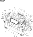
- An air compressor 1B illustrated in Fig. 3A includes a coupling member 81a that couples the upper end portion 80a of the handle portion 8a that partially covers the first air vent 73a and the upper end portion 80a of the handle portion 8b that partially covers the second air vent 73b.
- An air compressor 1C illustrated in Fig. 3B includes a coupling member 81b that couples the upper end portion 80a of the handle portion 8a that partially covers the first air vent 73a and the upper end portion 80a of the handle portion 8b that partially covers the second air vent 73b.
- the coupling members 81a and 81b are fixed to the upper surface portion 70 of the cover portion 7 by the screws 82 together with the upper end portions 80a of the handle portions 8a and 8b. As a result, the upper end portions 80a of the handle portions 8a and 8b are coupled via the upper surface portion 70 of the cover portion 7 and the coupling members 81a and 81b. Therefore, the strength of the pair of handle portions 8a and 8b provided to face each other in the rotation axis direction 40 of the air blowing unit 4 may be ensured.
- the handle portions 8a and 8b and the coupling members 81a and 81b are fixed to the upper surface portion 70 of the cover portion 7, so that the rigidity of the cover portion 7 may be increased, and damage due to deformation of the cover portion 7 may be reduced.
- the coupling member 81b is made of a flat plate-shaped member having a flat surface of a predetermined size, so that a portion having a flat surface may be configured on an upper surface of the air compressor 1C, and the portion may be used as a table on which a tool or the like is placed.
- the handle portion 8a that partially covers the first air vent 73a and the handle portion 8b that partially covers the second air vent 73b are integrally formed by a coupling portion 80h.
- the coupling portion 80h couples the upper end portion 80a of the handle portion 8a and the upper end portion 80a of the handle portion 8b and covers the upper surface portion 70 of the cover portion 7.
- the coupling portion 80h is formed of a flat plate-shaped member having a flat surface of a predetermined size, so that a portion having a flat surface may be configured on an upper surface of the air compressor 1D, and the portion may be used as a table on which a tool or the like is placed.
Landscapes
- Engineering & Computer Science (AREA)
- Mechanical Engineering (AREA)
- General Engineering & Computer Science (AREA)
- Compressors, Vaccum Pumps And Other Relevant Systems (AREA)
- Microelectronics & Electronic Packaging (AREA)
- Compressor (AREA)
Abstract
Description
- The present disclosure relates to a gas compressor that compresses gas.
- A gas compressor called an air compressor has a configuration in which a compression unit, an electric motor, and a fan are covered with a cover. an air vent for internal cooling is essential for the cover of the air compressor, and the air vent is configured by slits in a lattice shape or a row shape in order to prevent insertion of foreign matters (for example, see Patent Literature 1).
- Patent Literature 1:
JP2018-71467A - Since the air vent provided in the cover of the air compressor has a narrow portion between the slits, strength of a cover portion is reduced as compared with a portion where the air vent is not provided. On the other hand, in a portable air compressor used in a construction site or the like, a cover may receive an impact due to contact with a tool or a building material. Therefore, a portion of the cover where the air vent is provided is easily damaged. Therefore, it is conceivable to increase a thickness of the portion between the slits to improve the strength by reducing an opening area of the slit in the air vent. However, when the opening area of the slit is reduced, cooling efficiency is decreased.
- The present disclosure has been made to solve such a problem, and an object of the present disclosure is to provide a gas compressor capable of protecting a portion of a cover portion where an air vent is provided without lowering cooling efficiency.
- According to an aspect of the disclosure, a gas compressor includes a main body portion including a compression unit configured to compress gas, an air blowing unit, and a drive unit configured to drive the compression unit and the air blowing unit, a cover portion covering at least a part of the main body portion and having an air vent through which air flows from the air blowing unit, and a handle portion having a gripping portion. The air vent faces a rotation axis direction of a rotation member of the air blowing unit which is rotated by being driven by the drive unit, and the handle portion includes a protective portion facing the air vent and being apart from the air vent.
- In the present disclosure, the handle portion covers a part of the air vent on the outside of the cover portion, so that the handle portion prevents the air vent from being hit by an object. Further, a space is formed between the handle portion and the air vent by providing the protective portion apart from the air vent, so that the handle portion does not block a flow of air passing through the air vent. Accordingly, compared to a configuration in which an air vent is directly reinforced, the air vent may be protected by the handle portion without lowering the cooling efficiency.
-
-
Fig. 1A is a perspective view illustrating an example of an air compressor according to the present embodiment. -
Fig. 1B is a perspective view illustrating the example of the air compressor according to the present embodiment. -
Fig. 2 is a perspective view illustrating the example of the air compressor according to the present embodiment with a cover portion removed. -
Fig. 3A is a perspective view illustrating a modification of the air compressor according to the present embodiment. -
Fig. 3B is a perspective view illustrating a modification of the air compressor according to the present embodiment. -
Fig. 3C is a perspective view illustrating a modification of the air compressor according to the present embodiment. - Hereinafter, an embodiment of an air compressor as a gas compressor according to the present disclosure will be described with reference to the drawings.
- Configuration Example of Air Compressor according to Present Embodiment
-
Figs. 1A and1B are perspective views illustrating an example of an air compressor according to the present embodiment.Fig. 2 is a perspective view illustrating the example of the air compressor according to the present embodiment with a cover portion removed. - An
air compressor 1A includes acompression unit 2 that compresses air as an example of gas, adrive unit 3 that drives thecompression unit 2, an air blowingunit 4 that is driven by thedrive unit 3 and generates a flow of air for cooling thecompression unit 2 and thedrive unit 3, and astorage unit 5 that stores air (compressed air) compressed by thecompression unit 2. - The
air compressor 1A includes amain body portion 6 including thecompression unit 2, thedrive unit 3, the air blowingunit 4, and thestorage unit 5, acover portion 7 covering at least a part of themain body portion 6, and ahandle portion 8 that may be held by a human hand. An upper-lower direction of theair compressor 1A is determined in consideration of a usage form in which theair compressor 1A is installed in an installation place such as a ground or a floor of a building. - The
compression unit 2 includes aprimary cylinder 20a and asecondary cylinder 20b. Theprimary cylinder 20a and thesecondary cylinder 20b each include a piston (not illustrated). Each piston of theprimary cylinder 20a and thesecondary cylinder 20b in thecompression unit 2 is coupled to a crank shaft (not illustrated) rotatably supported by acrankcase 21. In thecompression unit 2, each piston reciprocates as the crank shaft rotates, and the reciprocating movement of each piston generates compressed air. Thecompression unit 2 further compresses, by thesecondary cylinder 20b, air compressed by theprimary cylinder 20a to generate higher pressure compressed air. - The
drive unit 3 is a motor (electric motor) driven by electricity. One side (not illustrated) of a rotatingshaft 30 of thedrive unit 3 is coupled to the crank shaft of thecompression unit 2. - The air blowing
unit 4 is formed of an axial fan, and is attached to the other side of theshaft 30 of thedrive unit 3. The air blowingunit 4 is rotated by being driven by thedrive unit 3 to generate an air flow from the air blowingunit 4 toward thedrive unit 3 and thecompression unit 2. - The
storage unit 5 includes a plurality oftanks 50 that store compressed air. In thetank 50, a radial direction of a cylindrical shape is a lateral direction, and a direction orthogonal to the radial direction (lateral direction) is a longitudinal direction. Thestorage unit 5 includes twotanks 50 in this embodiment. The twotanks 50 are arranged side by side in the radial direction such that the longitudinal directions of thetanks 50 are parallel to each other. - In the
main body portion 6, the crank shaft (not illustrated) of thecompression unit 2 is coupled to the one side of theshaft 30 of thedrive unit 3, and the air blowingunit 4 is attached to the other side of theshaft 30 of thedrive unit 3. Therefore, in themain body portion 6, a direction in which theshaft 30 of thedrive unit 3 extends is arotation axis direction 40 of the air blowingunit 4, and thecompression unit 2, thedrive unit 3, and the air blowingunit 4 are arranged coaxially along therotation axis direction 40 of the air blowingunit 4. Further, the longitudinal direction of eachtank 50 and the rotation axis direction 40 (the direction in which theshaft 30 of thedrive unit 3 extends) of the air blowingunit 4 are arranged in parallel. A length of thetank 50 in the longitudinal direction is longer than a length of thecompression unit 2, thedrive unit 3 and the air blowingunit 4 arranged along therotation axis direction 40 of the air blowingunit 4. As a result, when the longitudinal direction of eachtank 50 and therotation axis direction 40 of the air blowingunit 4 are arranged in parallel, it is easy to secure a space for thehandle portion 8 above both ends of thetank 50 along the longitudinal direction, and it is easy to secure a space between thehandle portion 8 and thecover portion 7. - In the
main body portion 6, the air blowingunit 4 is rotated by being driven by thedrive unit 3 to generate an air flow from the air blowingunit 4 toward thedrive unit 3 and thecompression unit 2 along therotation axis direction 40 of the air blowingunit 4 indicated by a dashed line inFig. 2 . - The
main body portion 6 includes acompressed air outlet 60 for supplying compressed air stored in thetank 50 of thestorage unit 5 to a tool (not illustrated). Thecompressed air outlet 60 is coupled to thetank 50 via apipe 61. In the embodiment, theair compressor 1A is provided with twocompressed air outlets 60, acompressed air outlet 60a for supplying high pressure compressed air and a compressedair outlet 60b for supplying relatively low pressure compressed air. Thecompressed air outlet 60a and thecompressed air outlet 60b are each provided with apressure reducing valve 62 for supplying compressed air reduced to a desired pressure to the tool and adial 63 for adjusting the pressure. - The
cover portion 7 includes anupper surface portion 70, afirst side portion 71a and asecond side portion 71b provided on both sides facing therotation axis direction 40 of the air blowingunit 4, and athird side portion 71c and a fourth side portion (not illustrated) provided on both sides facing a direction orthogonal to therotation axis direction 40 of the air blowingunit 4. - The
cover portion 7 has a shape that covers all thecompression unit 2, thedrive unit 3 and the air blowingunit 4, and an upper part of thestorage unit 5 with theupper surface portion 70, thefirst side portion 71a and thesecond side portion 71b, and thethird side portion 71c and the fourth side portion (not illustrated). Thecover portion 7 is fixed byscrews 74 to anattachment portion 52a provided on a peripheral surface of thetank 50 of thestorage unit 5. - The
cover portion 7 includes an airvent forming portion 72a on thefirst side portion 71a, which is one side portion facing therotation axis direction 40 of theair blowing unit 4. The airvent forming portion 72a is configured such that a portion where theupper surface portion 70 and thefirst side portion 71a are coupled to each other has a recessed shape. - Further, the
cover portion 7 includes an airvent forming portion 72b on thesecond side portion 71b, which is the other side portion facing therotation axis direction 40 of theair blowing unit 4. The airvent forming portion 72b is configured such that a portion where theupper surface portion 70 and thesecond side portion 71b are coupled to each other has a recessed shape. - The
cover portion 7 includes an air vent 73 (first air vent 73a) in the airvent forming portion 72a. Thefirst air vent 73a is configured by providing a plurality of slit-shape openings penetrating the front and back of thefirst side portion 71a. - Further, the
cover portion 7 includes an air vent 73 (second air vent 73b) in the airvent forming portion 72b. Thesecond air vent 73b is configured by providing a plurality of slit-shape openings penetrating the front and back of thesecond side portion 71b. - As a result, the air vents 73 (
first air vent 73a andsecond air vent 73b) are formed on both sides facing therotation axis direction 40 of theair blowing unit 4. In themain body portion 6, since the air flows from theair blowing unit 4 toward thedrive unit 3 and thecompression unit 2, thefirst air vent 73a facing theair blowing unit 4 serves as an intake port, and thesecond air vent 73b facing thecompression unit 2 serves as an outlet port. - The
handle portion 8 includes ahandle portion 8a that partially covers thefirst air vent 73a and ahandle portion 8b that partially covers thesecond air vent 73b. - The
handle portion 8a and thehandle portion 8b each includes anupper end portion 80a fixed to theupper surface portion 70 of thecover portion 7, alower end portion 80b fixed to thestorage unit 5 configuring themain body portion 6, twoprotective portions 80c coupling theupper end portion 80a and thelower end portion 80b and facing thefirst air vent 73a or thesecond air vent 73b, and agripping portion 80d to be held by hand. - The
upper end portion 80a is coupled to upper end sides of the twoprotective portions 80c such that a distance between the twoprotective portions 80c is approximately equal to a width of thefirst air vent 73a or thesecond air vent 73b. Thelower end portion 80b is coupled to lower end sides of the twoprotective portions 80c such that the distance between the twoprotective portions 80c is approximately equal to the width of thefirst air vent 73a or thesecond air vent 73b. - The
protective portion 80c is provided with abent portion 80e that is formed by bending a portion between theupper end portion 80a and thelower end portion 80b. Theprotective portion 80c has a shape that extends substantially vertically upward from thelower end portion 80b, extends toward the inside of themain body portion 6 at thebent portion 80e, and has theupper end portion 80a at an end portion thereof. As a result, in theprotective portion 80c, a space between theupper end portion 80a and thebent portion 80e forms an upperprotective portion 80f facing an upper part of thefirst air vent 73a and thesecond air vent 73b, and a space between thelower end portion 80b and thebent portion 80e forms a sideprotective portion 80g facing thefirst air vent 73a and thesecond air vent 73b. In thehandle portion 8a and thehandle portion 8b, the sideprotective portion 80g extends substantially vertically upward from thelower end portion 80b, and the upperprotective portion 80f extends inward from thebent portion 80e toward theupper surface portion 70 of thecover portion 7. - The gripping
portion 80d has a shape that couples the twoprotective portions 80c, and in this embodiment, couples thebent portions 80e of theprotective portions 80c. - The
upper end portion 80a of thehandle portion 8a is fixed to one end side of theupper surface portion 70 of thecover portion 7 withscrews 82. Further, thelower end portion 80b of thehandle portion 8a is fixed to anattachment portion 52b provided on one end side in the longitudinal direction of thetank 50 in thestorage unit 5 together with thecover portion 7 by a screw (not shown). - When the
handle portion 8a is attached to thecover portion 7 and the main body portion 6 (the storage unit 5), the twoprotective portions 80c and the grippingportion 80d cover a portion on a front surface side of thefirst air vent 73a along therotation axis direction 40 of theair blowing unit 4. In theprotective portion 80c, the upperprotective portion 80f between theupper end portion 80a and thebent portion 80e faces the upper part of thefirst air vent 73a, and the sideprotective portion 80g between thelower end portion 80b and thebent portion 80e faces thefirst air vent 73a. - As a result, the
handle portion 8a protects thefirst air vent 73a by reducing contact of any object from a side surface and an upper surface of thefirst air vent 73a. - In the
handle portion 8a, theprotective portion 80c has a protruding shape at thebent portion 80e with respect to the airvent forming portion 72a which has a recessed shape, theprotective portion 80c (the upperprotective portion 80f and the sideprotective portion 80g) is provided apart from thefirst air vent 73a, and a space is formed between theprotective portion 80c and thefirst air vent 73a. As a result, thehandle portion 8a does not block a flow of air sucked into thecover portion 7 through thefirst air vent 73a. - Accordingly, as compared with a configuration in which the
first air vent 73a is directly reinforced, thefirst air vent 73a may be protected by thehandle portion 8a without reducing the opening area of thefirst air vent 73a. - The
upper end portion 80a of thehandle portion 8b is fixed to the other end side of theupper surface portion 70 of thecover portion 7 withscrews 82. Further, thelower end portion 80b of thehandle portion 8b is fixed to anattachment portion 52b provided on the other end side in the longitudinal direction of thetank 50 in thestorage unit 5 together with thecover portion 7 by a screw (not shown). - When the
handle portion 8b is attached to thecover portion 7 and the main body portion 6 (the storage unit 5), the twoprotective portions 80c and the grippingportion 80d cover a portion on a front surface side of thesecond air vent 73b along therotation axis direction 40 of theair blowing unit 4. In theprotective portion 80c, the upperprotective portion 80f between theupper end portion 80a and thebent portion 80e faces the upper part of thesecond air vent 73b, and the sideprotective portion 80g between thelower end portion 80b and thebent portion 80e faces thesecond air vent 73b. - As a result, the
handle portion 8b protects thesecond air vent 73b by reducing contact of any object from a side surface and an upper surface of thesecond air vent 73b. - In the
handle portion 8b, theprotective portion 80c has a protruding shape at thebent portion 80e with respect to the airvent forming portion 72b which has a recessed shape, theprotective portion 80c (the upperprotective portion 80f and the sideprotective portion 80g) is provided apart from thesecond air vent 73b, and a space is formed between theprotective portion 80c and thesecond air vent 73b. As a result, thehandle portion 8b does not block a flow of air discharged from thesecond air vent 73b. - Accordingly, as compared with a configuration in which the
second air vent 73b is directly reinforced, thesecond air vent 73b may be protected by thehandle portion 8b without reducing the opening area of thesecond air vent 73b. - The
handle portion 8a and thehandle portion 8b secure strength by increasing a thickness of each portion so that theheavy air compressor 1A may be carried. Further, thehandle portion 8a and thehandle portion 8b may secure the strength by coupling the twoprotective portions 80c by the grippingportion 80d at the position of thebent portion 80e between theupper end portion 80a and thelower end portion 80b. Theupper end portions 80a of thehandle portions upper surface portion 70 of thecover portion 7. - In a configuration in which the periphery of an air vent is not protected by a handle in a cover portion of an air compressor having the air vent, for example, when a load is applied to the cover portion from above, the vicinity of the air vent having low strength is particularly largely deformed, and the vicinity of the air vent is easily damaged. In contrast, the
upper surface portion 70 of thecover portion 7 and the lower end side of thecover portion 7 coupled to thestorage unit 5 are coupled by thehandle portion 8a and thehandle portion 8b with secured strength, so that rigidity of thecover portion 7 is increased, and damage due to deformation of thecover portion 7 may be reduced. - In the
handle portion 8a and thehandle portion 8b, the upperprotective portion 80f extends obliquely upward with respect to a horizontal direction from thebent portion 80e, and theupper end portion 80a is fixed to theupper surface portion 70 of thecover portion 7. As a result, a load applied to theupper surface portion 70 of thecover portion 7 may be transmitted to thestorage unit 5 to which the respectivelower end portions 80b of thehandle portions handle portions - The
upper surface portion 70 of thecover portion 7 has a shape having a flat surface of a predetermined size at least in part, and may be used as a table on which a tool or the like is placed. Further, theupper surface portion 70 of thecover portion 7 is provided withuneven ribs 70a to increase the strength of theupper surface portion 70. As a result, when a tool or the like is placed on theupper surface portion 70 of thecover portion 7, a load of the tool or the like is reduced by being absorbed due to deformation of theupper surface portion 70 of thecover portion 7, and the load is transmitted to thehandle portions cover portion 7. Further, when the upperprotective portion 80f of thehandle portion 8a and thehandle portion 8b extends horizontally, an area of theupper surface portion 70 of thecover portion 7 forming the flat surface may be expanded. -
Figs. 3A ,3B , and3C are perspective views illustrating a modification of the air compressor according to the present embodiment. - An
air compressor 1B illustrated inFig. 3A includes acoupling member 81a that couples theupper end portion 80a of thehandle portion 8a that partially covers thefirst air vent 73a and theupper end portion 80a of thehandle portion 8b that partially covers thesecond air vent 73b. Anair compressor 1C illustrated inFig. 3B includes acoupling member 81b that couples theupper end portion 80a of thehandle portion 8a that partially covers thefirst air vent 73a and theupper end portion 80a of thehandle portion 8b that partially covers thesecond air vent 73b. - The
coupling members upper surface portion 70 of thecover portion 7 by thescrews 82 together with theupper end portions 80a of thehandle portions upper end portions 80a of thehandle portions upper surface portion 70 of thecover portion 7 and thecoupling members handle portions rotation axis direction 40 of theair blowing unit 4 may be ensured. In addition, thehandle portions coupling members upper surface portion 70 of thecover portion 7, so that the rigidity of thecover portion 7 may be increased, and damage due to deformation of thecover portion 7 may be reduced. Thecoupling member 81b is made of a flat plate-shaped member having a flat surface of a predetermined size, so that a portion having a flat surface may be configured on an upper surface of theair compressor 1C, and the portion may be used as a table on which a tool or the like is placed. - In an
air compressor 1D illustrated inFig. 3C , thehandle portion 8a that partially covers thefirst air vent 73a and thehandle portion 8b that partially covers thesecond air vent 73b are integrally formed by acoupling portion 80h. Thecoupling portion 80h couples theupper end portion 80a of thehandle portion 8a and theupper end portion 80a of thehandle portion 8b and covers theupper surface portion 70 of thecover portion 7. - As a result, the
handle portion 8a and thehandle portion 8b are coupled integrally, so that the strength of the pair ofhandle portions rotation axis direction 40 of theair blowing unit 4 may be ensured. Thecoupling portion 80h is formed of a flat plate-shaped member having a flat surface of a predetermined size, so that a portion having a flat surface may be configured on an upper surface of theair compressor 1D, and the portion may be used as a table on which a tool or the like is placed.
Claims (12)
- A gas compressor comprising:a main body portion including:a compression unit configured to compress gas;an air blowing unit; anda drive unit configured to drive the compression unit and the air blowing unit;a cover portion covering at least a part of the main body portion and having an air vent through which air flows; anda handle portion having a gripping portion,wherein the air vent faces a rotation axis direction of a rotation member of the air blowing unit which is rotated by being driven by the drive unit, andthe handle portion includes a protective portion facing the air vent and being apart from the air vent.
- The gas compressor according to claim 1,wherein the protective portion includes an upper protective portion facing an upper portion of the air vent and a side protective portion facing a front portion of the air vent, andwherein the upper protective portion and the side protective portion are apart from the air vent.
- The gas compressor according to claim 1, wherein an upper end side of the protective portion includes an upper end portion configured to be fixed to an upper surface portion of the cover portion, and a lower end side of the protective portion includes a lower end portion configured to be fixed to the main body portion.
- The gas compressor according to claim 1, wherein the protective portion includes two protective portions a distance of which corresponds to a width of the air vent.
- The gas compressor according to claim 1, wherein the protective portion includes two protective portions disposed on both sides of the cover portion in the rotation axis direction of the rotation member of the air blowing unit.
- The gas compressor according to claim 5, wherein the handle portion includes a coupling portion that covers and is coupled with at least a part of an upper surface portion of the cover portion.
- The gas compressor according to claim 5, wherein the handle portion is coupled with the cover portion with a coupling member that covers at least a part of an upper surface portion of the cover portion.
- The gas compressor according to claim 1 further comprising a storage unit configured to stores air compressed by the compression unit,
wherein the rotation axis direction of the rotation member corresponds to a longitudinal direction of the storage unit. - The gas compressor according to claim 1, wherein the cover portion covers a side face of the main body portion.
- The gas compressor according to claim 4, the gripping portion is disposed between the two protective portions.
- The gas compressor according to claim 1, the protective portion includes a first portion extending along the rotation axis direction of the rotation member and a second portion extending downward from an end portion of the first portion.
- The gas compressor according to claim 11, the gripping portion laterally extends from the end portion of the first portion.
Applications Claiming Priority (1)
| Application Number | Priority Date | Filing Date | Title |
|---|---|---|---|
| JP2022074681A JP7797954B2 (en) | 2022-04-28 | 2022-04-28 | Gas compressor |
Publications (1)
| Publication Number | Publication Date |
|---|---|
| EP4269793A1 true EP4269793A1 (en) | 2023-11-01 |
Family
ID=86226647
Family Applications (1)
| Application Number | Title | Priority Date | Filing Date |
|---|---|---|---|
| EP23169828.3A Withdrawn EP4269793A1 (en) | 2022-04-28 | 2023-04-25 | Gas compressor |
Country Status (3)
| Country | Link |
|---|---|
| US (1) | US12442366B2 (en) |
| EP (1) | EP4269793A1 (en) |
| JP (1) | JP7797954B2 (en) |
Citations (6)
| Publication number | Priority date | Publication date | Assignee | Title |
|---|---|---|---|---|
| US20080003112A1 (en) * | 2006-06-08 | 2008-01-03 | Schuetzle Larry A | Reciprocating compressor or pump and a portable tool powering system including a reciprocating compressor |
| US20080112823A1 (en) * | 2004-12-28 | 2008-05-15 | Tsutomu Yoshida | Air Compressor |
| US20090194177A1 (en) * | 2008-02-05 | 2009-08-06 | Hitachi Koki Co., Ltd. | Air compressor |
| US8770341B2 (en) * | 2011-09-13 | 2014-07-08 | Black & Decker Inc. | Compressor intake muffler and filter |
| JP2018071467A (en) | 2016-10-31 | 2018-05-10 | 日立工機株式会社 | Gas compressor |
| US20220112903A1 (en) * | 2020-11-10 | 2022-04-14 | Intradin (Shanghai) Machinery Co., Ltd. | Air compressor |
Family Cites Families (4)
| Publication number | Priority date | Publication date | Assignee | Title |
|---|---|---|---|---|
| JP2009024604A (en) * | 2007-07-19 | 2009-02-05 | Max Co Ltd | Portable air compressor |
| JP2013163981A (en) * | 2012-02-09 | 2013-08-22 | Hitachi Koki Co Ltd | Air compressor |
| JP6790735B2 (en) * | 2016-11-03 | 2020-11-25 | マックス株式会社 | Air compressor |
| JP7471951B2 (en) | 2020-08-06 | 2024-04-22 | 株式会社マキタ | Air Compressor |
-
2022
- 2022-04-28 JP JP2022074681A patent/JP7797954B2/en active Active
-
2023
- 2023-04-25 US US18/139,087 patent/US12442366B2/en active Active
- 2023-04-25 EP EP23169828.3A patent/EP4269793A1/en not_active Withdrawn
Patent Citations (6)
| Publication number | Priority date | Publication date | Assignee | Title |
|---|---|---|---|---|
| US20080112823A1 (en) * | 2004-12-28 | 2008-05-15 | Tsutomu Yoshida | Air Compressor |
| US20080003112A1 (en) * | 2006-06-08 | 2008-01-03 | Schuetzle Larry A | Reciprocating compressor or pump and a portable tool powering system including a reciprocating compressor |
| US20090194177A1 (en) * | 2008-02-05 | 2009-08-06 | Hitachi Koki Co., Ltd. | Air compressor |
| US8770341B2 (en) * | 2011-09-13 | 2014-07-08 | Black & Decker Inc. | Compressor intake muffler and filter |
| JP2018071467A (en) | 2016-10-31 | 2018-05-10 | 日立工機株式会社 | Gas compressor |
| US20220112903A1 (en) * | 2020-11-10 | 2022-04-14 | Intradin (Shanghai) Machinery Co., Ltd. | Air compressor |
Also Published As
| Publication number | Publication date |
|---|---|
| US12442366B2 (en) | 2025-10-14 |
| JP2023163645A (en) | 2023-11-10 |
| JP7797954B2 (en) | 2026-01-14 |
| US20230354532A1 (en) | 2023-11-02 |
Similar Documents
| Publication | Publication Date | Title |
|---|---|---|
| US20050063840A1 (en) | Air compressor having stable configuration | |
| EP2333435A2 (en) | Bell-mouth structure of air blower | |
| US8297957B2 (en) | Compressor | |
| CN206988119U (en) | Compressor and its delivery valve seat and delivery valve seat component | |
| US20090044554A1 (en) | Shut-off valve support member and outdoor unit of air conditioner provided with the same | |
| JP4750551B2 (en) | Method for manufacturing two-cylinder rotary hermetic compressor | |
| EP4092269B1 (en) | Air compressor | |
| US20090110567A1 (en) | Air Compressor | |
| US12442366B2 (en) | Gas compressor | |
| EP3816442B1 (en) | Compressor and electronic device using same | |
| EP2853745A1 (en) | Air compressor | |
| JP2022167841A (en) | Air stop sheet of piston body of cylinder | |
| JP5335703B2 (en) | Reciprocating compressor | |
| US7070397B2 (en) | Compressor suction gas feed assembly | |
| JP7669228B2 (en) | Air Compressor | |
| CN108730157B (en) | Linear compressor | |
| JP5098463B2 (en) | air compressor | |
| JP2017075576A (en) | Tank-integrated fluid compressor | |
| CN1811287A (en) | Outdoor unit for air conditioner | |
| JP7167485B2 (en) | gas compressor | |
| EP4269794A2 (en) | Gas compressor, auxiliary storage unit, and gas compression system | |
| KR102041118B1 (en) | Rotary compressor | |
| JP4538818B2 (en) | Reciprocating compressor | |
| JP7835983B2 (en) | Work equipment | |
| JP5253272B2 (en) | Electric construction machine |
Legal Events
| Date | Code | Title | Description |
|---|---|---|---|
| PUAI | Public reference made under article 153(3) epc to a published international application that has entered the european phase |
Free format text: ORIGINAL CODE: 0009012 |
|
| STAA | Information on the status of an ep patent application or granted ep patent |
Free format text: STATUS: THE APPLICATION HAS BEEN PUBLISHED |
|
| AK | Designated contracting states |
Kind code of ref document: A1 Designated state(s): AL AT BE BG CH CY CZ DE DK EE ES FI FR GB GR HR HU IE IS IT LI LT LU LV MC ME MK MT NL NO PL PT RO RS SE SI SK SM TR |
|
| STAA | Information on the status of an ep patent application or granted ep patent |
Free format text: STATUS: REQUEST FOR EXAMINATION WAS MADE |
|
| 17P | Request for examination filed |
Effective date: 20240425 |
|
| RBV | Designated contracting states (corrected) |
Designated state(s): AL AT BE BG CH CY CZ DE DK EE ES FI FR GB GR HR HU IE IS IT LI LT LU LV MC ME MK MT NL NO PL PT RO RS SE SI SK SM TR |
|
| GRAP | Despatch of communication of intention to grant a patent |
Free format text: ORIGINAL CODE: EPIDOSNIGR1 |
|
| STAA | Information on the status of an ep patent application or granted ep patent |
Free format text: STATUS: GRANT OF PATENT IS INTENDED |
|
| INTG | Intention to grant announced |
Effective date: 20250226 |
|
| STAA | Information on the status of an ep patent application or granted ep patent |
Free format text: STATUS: THE APPLICATION IS DEEMED TO BE WITHDRAWN |
|
| 18D | Application deemed to be withdrawn |
Effective date: 20250627 |