EP4269778A1 - Straddled vehicle - Google Patents
Straddled vehicle Download PDFInfo
- Publication number
- EP4269778A1 EP4269778A1 EP23164946.8A EP23164946A EP4269778A1 EP 4269778 A1 EP4269778 A1 EP 4269778A1 EP 23164946 A EP23164946 A EP 23164946A EP 4269778 A1 EP4269778 A1 EP 4269778A1
- Authority
- EP
- European Patent Office
- Prior art keywords
- air cleaner
- cover
- opening
- space
- intake port
- Prior art date
- Legal status (The legal status is an assumption and is not a legal conclusion. Google has not performed a legal analysis and makes no representation as to the accuracy of the status listed.)
- Granted
Links
Images




Classifications
-
- F—MECHANICAL ENGINEERING; LIGHTING; HEATING; WEAPONS; BLASTING
- F02—COMBUSTION ENGINES; HOT-GAS OR COMBUSTION-PRODUCT ENGINE PLANTS
- F02M—SUPPLYING COMBUSTION ENGINES IN GENERAL WITH COMBUSTIBLE MIXTURES OR CONSTITUENTS THEREOF
- F02M35/00—Combustion-air cleaners, air intakes, intake silencers, or induction systems specially adapted for, or arranged on, internal-combustion engines
- F02M35/10—Air intakes; Induction systems
- F02M35/10006—Air intakes; Induction systems characterised by the position of elements of the air intake system in direction of the air intake flow, i.e. between ambient air inlet and supply to the combustion chamber
- F02M35/10013—Means upstream of the air filter; Connection to the ambient air
-
- B—PERFORMING OPERATIONS; TRANSPORTING
- B62—LAND VEHICLES FOR TRAVELLING OTHERWISE THAN ON RAILS
- B62J—CYCLE SADDLES OR SEATS; AUXILIARY DEVICES OR ACCESSORIES SPECIALLY ADAPTED TO CYCLES AND NOT OTHERWISE PROVIDED FOR, e.g. ARTICLE CARRIERS OR CYCLE PROTECTORS
- B62J35/00—Fuel tanks specially adapted for motorcycles or engine-assisted cycles; Arrangements thereof
-
- B—PERFORMING OPERATIONS; TRANSPORTING
- B62—LAND VEHICLES FOR TRAVELLING OTHERWISE THAN ON RAILS
- B62J—CYCLE SADDLES OR SEATS; AUXILIARY DEVICES OR ACCESSORIES SPECIALLY ADAPTED TO CYCLES AND NOT OTHERWISE PROVIDED FOR, e.g. ARTICLE CARRIERS OR CYCLE PROTECTORS
- B62J40/00—Arrangements of air cleaners specially adapted for cycles
-
- B—PERFORMING OPERATIONS; TRANSPORTING
- B62—LAND VEHICLES FOR TRAVELLING OTHERWISE THAN ON RAILS
- B62K—CYCLES; CYCLE FRAMES; CYCLE STEERING DEVICES; RIDER-OPERATED TERMINAL CONTROLS SPECIALLY ADAPTED FOR CYCLES; CYCLE AXLE SUSPENSIONS; CYCLE SIDECARS, FORECARS, OR THE LIKE
- B62K11/00—Motorcycles, engine-assisted cycles or motor scooters with one or two wheels
- B62K11/02—Frames
- B62K11/04—Frames characterised by the engine being between front and rear wheels
-
- F—MECHANICAL ENGINEERING; LIGHTING; HEATING; WEAPONS; BLASTING
- F02—COMBUSTION ENGINES; HOT-GAS OR COMBUSTION-PRODUCT ENGINE PLANTS
- F02M—SUPPLYING COMBUSTION ENGINES IN GENERAL WITH COMBUSTIBLE MIXTURES OR CONSTITUENTS THEREOF
- F02M35/00—Combustion-air cleaners, air intakes, intake silencers, or induction systems specially adapted for, or arranged on, internal-combustion engines
- F02M35/10—Air intakes; Induction systems
- F02M35/10242—Devices or means connected to or integrated into air intakes; Air intakes combined with other engine or vehicle parts
- F02M35/10262—Flow guides, obstructions, deflectors or the like
-
- F—MECHANICAL ENGINEERING; LIGHTING; HEATING; WEAPONS; BLASTING
- F02—COMBUSTION ENGINES; HOT-GAS OR COMBUSTION-PRODUCT ENGINE PLANTS
- F02M—SUPPLYING COMBUSTION ENGINES IN GENERAL WITH COMBUSTIBLE MIXTURES OR CONSTITUENTS THEREOF
- F02M35/00—Combustion-air cleaners, air intakes, intake silencers, or induction systems specially adapted for, or arranged on, internal-combustion engines
- F02M35/10—Air intakes; Induction systems
- F02M35/10242—Devices or means connected to or integrated into air intakes; Air intakes combined with other engine or vehicle parts
- F02M35/10288—Air intakes combined with another engine part, e.g. cylinder head cover or being cast in one piece with the exhaust manifold, cylinder head or engine block
-
- F—MECHANICAL ENGINEERING; LIGHTING; HEATING; WEAPONS; BLASTING
- F02—COMBUSTION ENGINES; HOT-GAS OR COMBUSTION-PRODUCT ENGINE PLANTS
- F02M—SUPPLYING COMBUSTION ENGINES IN GENERAL WITH COMBUSTIBLE MIXTURES OR CONSTITUENTS THEREOF
- F02M35/00—Combustion-air cleaners, air intakes, intake silencers, or induction systems specially adapted for, or arranged on, internal-combustion engines
- F02M35/12—Intake silencers ; Sound modulation, transmission or amplification
- F02M35/1294—Amplifying, modulating, tuning or transmitting sound, e.g. directing sound to the passenger cabin; Sound modulation
-
- F—MECHANICAL ENGINEERING; LIGHTING; HEATING; WEAPONS; BLASTING
- F02—COMBUSTION ENGINES; HOT-GAS OR COMBUSTION-PRODUCT ENGINE PLANTS
- F02M—SUPPLYING COMBUSTION ENGINES IN GENERAL WITH COMBUSTIBLE MIXTURES OR CONSTITUENTS THEREOF
- F02M35/00—Combustion-air cleaners, air intakes, intake silencers, or induction systems specially adapted for, or arranged on, internal-combustion engines
- F02M35/16—Combustion-air cleaners, air intakes, intake silencers, or induction systems specially adapted for, or arranged on, internal-combustion engines characterised by use in vehicles
- F02M35/162—Motorcycles; All-terrain vehicles, e.g. quads, snowmobiles; Small vehicles, e.g. forklifts
Definitions
- the present invention relates to a straddled vehicle including an engine and an air cleaner.
- An air cleaner introduces clean air into an engine. During traveling of a straddled vehicle including an engine, an intake sound may be generated from an air cleaner.
- the rider can enjoy driving the straddled vehicle by actively hearing the intake sound. Further, in a case in which an intake sound generated from the air cleaner changes in accordance with the work state of the engine, the rider can perform a throttle operation, a handle operation and the like while identifying the work state of the engine by actively hearing the intake sound.
- JP 2019-172097 A describes one example of a straddled vehicle in which an air cleaner box is provided rearwardly of an engine.
- an intake port is provided in the sidewall of the air cleaner box.
- a side cover is provided so as to cover the intake port in the sidewall of the air cleaner box from the side of the straddle vehicle.
- a side cover opening for allowing a rider to hear an intake sound generated from the air cleaner box is formed.
- the above-mentioned side cover is located directly below a seat and relatively away from the head of the rider riding the straddled vehicle. Further, the side cover opening is formed so as to be directed sidewardly of the vehicle. Therefore, in regard to the straddled vehicle of JP 2019-172097 A , it is difficult for a driver riding the straddled vehicle to actually hear an intake sound generated from the air cleaner box.
- JP 2009-73287 A describes one example of the configuration of a straddled vehicle in which an intake box (air cleaner box) is provided in an upper portion of an engine.
- a cover that covers a key cylinder is provided above an air inlet port (intake port) of the intake box.
- An opening directed upwardly is formed in the cover.
- JP 2009-73287 A further describes the configuration in which a duct extending from the intake box toward the opening of the cover is provided in order to enhance the effect of collecting an intake sound in the opening of the cover.
- the duct is formed so as to open toward the opening of the cover and communicate with the space above the duct and the space below the duct (the inner space of the air intake box). Therefore, with the above-mentioned configuration, droplets of rainwater or the like may enter the opening of the cover.
- a duct filter for capturing dust is provided in the duct. However, the duct filter cannot prevent droplets from flowing into the intake box through the duct.
- An object of the present invention is to provide a straddled vehicle that enable a rider to efficiently hear an intake sound of an air cleaner while suppressing entry of a large amount of droplets into the air cleaner.
- the air cleaner is provided above the engine.
- the engine provided in the straddled vehicle is located between or in front of both feet of a rider riding the straddled vehicle. Therefore, with the above-mentioned arrangement, the air cleaner is located farther downwardly than the rider's head in a portion of the straddled vehicle that is relatively close to the rider's head.
- the intake port of the air cleaner is opened upwardly. Further, at least part of the opening of the cover overlaps with the intake port of the air cleaner in a plan view. Therefore, during the work of the engine, an intake sound generated in the intake port of the air cleaner is output upwardly of the cover through at least part of the opening of the cover. Therefore, the rider can easily hear an intake sound generated from the air cleaner.
- the shielding member is provided between the air cleaner and the cover such that at least part of the shielding member overlaps with the common opening region in a plan view.
- the shielding member reduces further entry of droplets of rainwater or the like, which enters the opening of the cover, into the intake port of the air cleaner.
- At least part of the shielding member may overlap with the entire common opening region in a plan view. In this case, a large portion of droplets entering the space between the cover and the air cleaner through the opening of the cover is received by the shielding member and flows to a region away from the intake port of the air cleaner in a plan view. This prevents droplets of rainwater or the like from entering the intake port of the air cleaner.
- the straddled vehicle may further include a fuel tank, wherein the shielding member may be constituted by at least part of the fuel tank.
- the fuel tank has a fuel storage space for storing fuel therein.
- the fuel storage space is included in the portion of the shielding member that overlaps with the common opening region in a plan view.
- the fuel storage space of the fuel tank functions as a sound absorber that well absorbs a sound having a specific frequency.
- the sound absorbing function of the fuel storage space of the fuel tank changes in accordance with the state in the fuel storage space, that is, whether the fuel storage space is filled with fuel.
- an intake sound output from the opening of the cover changes in accordance with the state in the fuel storage space. Therefore, the rider can identify the remaining amount of fuel by hearing an intake sound generated from the air cleaner.
- the straddled vehicle may further include a fuel tank, and a tank protection member that protects the fuel tank, wherein the shielding member may be constituted by at least part of the fuel tank and the tank protection member.
- a sound transmission space that is formed so as to continuously extend from the intake port of the air cleaner to the opening of the cover while bypassing the shielding member may be formed between the air cleaner and the cover.
- the cover, the air cleaner and the shielding member form a so-called labyrinth structure that restricts a flow of fluid between the space in the air cleaner and the space above the cover.
- the sound transmission space is formed in a zigzag manner between the opening of the cover and the intake port of the air cleaner in a predetermined vertical cross section. Therefore, even in a case in which droplets of rainwater or the like enter the space between the shielding member and the cover from the opening of the cover, further entry of the droplets into the intake port of the air cleaner is reduced. Further, an intake sound generated in the intake port of the air cleaner is output from the opening of the cover through the sound transmission space.
- the sound transmission space may include a clearance space located between the cover and the shielding member, a partitioning portion that partitions the clearance space into a first space and a second space may be provided at at least one of the cover and the shielding member, the first space may be a space that communicates with a space above the cover through the opening of the cover, and the second space may be a space excluding the first space in the clearance space.
- a sum of an opening area of the opening of the cover may be equal to or smaller than a sum of an opening area of the intake port of the air cleaner.
- the volume of an intake sound output upwardly from the intake port of the air cleaner is referred to as a first sound output volume.
- the volume of an intake sound output upwardly from the opening of the cover is referred to as a second sound output volume.
- the first sound output volume is defined in accordance with the total opening area of the intake port of the air cleaner.
- the second sound output volume is defined in accordance with the sum of the opening area of the opening of the cover.
- the intake port of the air cleaner In the output path of the intake sound of the air cleaner, the intake port of the air cleaner is located at a position farther upstream than the opening of the cover. Therefore, in a case in which the sum of the opening area of the opening of the cover is larger than the sum of the opening area of the intake port of the air cleaner, the volume of an output sound is defined based on not the sum of the opening area of the opening of the cover but the sum of the opening area of the intake port of the air cleaner.
- the volume of an output sound is defined in accordance with the sum of the opening area of the opening of the cover.
- the dimension of the opening of the cover can be determined such that the second sound output volume is a desired sound volume.
- the opening of the cover may include a first opening and a second opening, each of the first opening and the second opening may be formed such that at least part of each of the first opening and the second opening overlaps with the intake port of the air cleaner in a plan view, the shielding member may be configured to overlap with at least part of the first opening of the cover in a plan view and may be configured to overlap with at least part of the second opening of the cover in a plan view.
- a straddled vehicle according to one embodiment of the present invention will be described below with reference to the drawings.
- a motorcycle will be described as one example of the straddled vehicle.
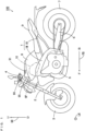
- Fig. 1 is a side view of a motorcycle 100 according to one embodiment of the present invention.
- the motorcycle 100 standing up to be perpendicular to the road surface is shown.
- a front-and-rear direction FB, a left-and-right direction LR and an up-and-down direction UD of the motorcycle 100 are suitably indicated by the arrows.
- the direction in which the arrow is directed in the front-and-rear direction FB is referred to as forward, and its opposite direction is referred to as rearward.
- the direction in which the arrow is directed in the left-and-right direction LR is referred to as leftward, and its opposite direction is referred to as rightward.
- the motorcycle 100 of Fig. 1 includes a metallic body frame 1.
- the body frame 1 includes a main frame 1M and a rear frame 1R.
- the front end portion of the main frame 1M constitutes a head pipe HP.
- the main frame 1M is formed to extend rearwardly and downwardly from the head pipe HP.
- the rear frame 1R is attached to the main frame 1M so as to extend rearwardly and slightly upwardly from the rear end portion of the main frame 1M and its vicinity.
- a front fork 2 is provided at the head pipe HP to be rotatable about the center axis of the head pipe HP.
- a front wheel 3 is rotatably supported at the lower end portion of the front fork 2.
- a handle 4 is provided at the upper end portion of the front fork 2.
- the main frame 1M supports an engine 5 at a position farther downward than the head pipe HP.
- An air cleaner 10 and a fuel tank 8 are provided to be located upwardly of the engine 5 and rearwardly of the head pipe HP.
- the air cleaner 10 and the fuel tank 8 are supported by the main frame 1M and at least part of the air cleaner 10 and the fuel tank 8 is located above the main frame 1M.
- Part of the fuel tank 8 is located above the air cleaner 10.
- An upper cover 90 is attached to the fuel tank 8 so as to cover part of the air cleaner 10 and part of the fuel tank 8 from above.
- a pair of left and right cover openings 91 is formed in the upper cover 90. In Fig. 1 , only the left cover opening 91 of the pair of cover openings 91 is shown.
- a key cylinder 95 is provided to be adjacent to the front end portion of the upper cover 90. The key cylinder 95 is supported at the main frame 1M.
- a seat 9 is provided rearwardly of the fuel tank 8. The seat 9 is mainly supported by the rear frame 1R and located above the rear frame 1R.
- a rear arm 6 is provided to extend rearwardly from a lower portion at the rear end of the main frame 1M.
- the rear arm 6 is supported at the main frame 1M via a pivot shaft.
- a rear wheel 7 is rotatably supported at the rear end portion of the rear arm 6. The rear wheel 7 is rotated as a drive wheel by the motive power generated from the engine 5.
- the air cleaner 10 is mainly constituted by an air cleaner case and a filter element (not shown).
- the filter element is provided in the air cleaner case. During traveling of the motorcycle 100, air outside of the motorcycle 100 is guided to the inner space of the air cleaner case, and is supplied to the engine 5 while being cleaned by the filter element.
- the air cleaner 10 has an intake port 11 (see Fig. 2 , described below) into which air to be supplied to the engine 5 is introduced.
- an intake sound is generated.
- an intake sound is an intake sound that gives a rider the feeling of sprinting
- the rider can enjoy driving the motorcycle 100 by hearing the intake sound.
- an intake sound changes in accordance with the work state of the engine
- the driver can identify the work state of the engine by hearing the intake sound.
- the configurations of the air cleaner 10 and its peripheral members are devised.
- the configurations of the air cleaner 10 and its peripheral members will be described below in detail.
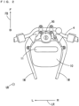
- Fig. 2 is a plan view of the air cleaner 10 of Fig. 1 .
- the air cleaner 10 of Fig. 1 being attached to the main frame 1M is shown.
- Fig. 2 shows the key cylinder 95 and the handle 4 of Fig. 1 together with the air cleaner 10.
- the air cleaner 10 has the intake port 11.
- the intake port 11 is formed so as to open upwardly.
- the intake port 11 of the present example is located in the vicinity of the front end portion of the air cleaner 10 and extends in the left-and-right direction LR of the motorcycle 100 while having a substantially constant width in a plan view.
- the fuel tank 8 is attached to the main frame 1M so as to cover a large portion of the air cleaner 10 from above with the air cleaner 10 being attached to the main frame 1M.
- Fig. 3 is a plan view showing the fuel tank 8 being provided on the air cleaner 10 of Fig. 2 .
- hatching is applied to the fuel tank 8 in order to facilitate understanding of the shape of the fuel tank 8.
- the fuel tank 8 of the present example covers a large portion of the air cleaner 10 from above except for the front end portion of the air cleaner 10 in a plan view. Further, the fuel tank 8 overlaps with the entire intake port 11 of the air cleaner 10 in a plan view. Further, a fuel cap 81 is provided at the substantially central portion of the upper surface of the fuel tank 8.
- One end portion of a harness 82 is connected to part of the fuel cap 81.
- the other end portion of the harness 82 is connected to a harness connecting portion 89 provided in the vicinity of the key cylinder 95.
- Part of the harness 82 overlaps with part of the fuel tank 8 in a plan view.
- the harness 82 is provided with a play for ensuring easiness of attachment and detachment work and ensuring stability of the connection state.
- the harness 82 is flexible. Therefore, during traveling of the motorcycle 100, when the harness 82 swings with the harness 82 and the fuel tank 8 being in contact with each other, part of the surface of the fuel tank 8 may wear due to the contact with the harness 82.
- a tank protection member 70 (see Fig. 4 , described below) is attached to the fuel tank 8 in order to prevent the contact between the fuel tank 8 and the harness 82.
- the tank protection member 70 covers part of the upper surface of the fuel tank 8.
- Fig. 4 is a plan view showing the tank protection member 70 being attached to the fuel tank 8 of Fig. 3 .
- hatching is applied to the fuel tank 8
- a dotted pattern is applied to the tank protection member 70.
- an enlarged plan view of the tank protection member 70 is shown in the balloon.
- the tank protection member 70 of the present example is provided so as to overlap with a portion of the upper surface of the fuel tank 8 located forwardly of the fuel cap 81 and be located between the fuel tank 8 and the harness 82 in a plan view.
- the tank protection member 70 is a substantially plate-shaped single member formed of resin having relatively high rigidity, and has a pair of left and right sound transmission portions 71, a pair of left and right wire holding portions 72 and a coupling portion 73.
- the pair of wire holding portions 72 is arranged at the left and right of the coupling portion 73.
- Each wire holding portion 72 is adjacent to the coupling portion 73.
- the pair of sound transmission portions 71 are arranged at the left and right of the pair of wire holding portions 72.
- the right sound transmission portion 71 is adjacent to the right wire holding portion 72
- the left sound transmission portion 71 is adjacent to the left wire holding portion 72.
- the pair of sound transmission portions 71, the pair of wire holding portions 72 and the coupling portion 73 of the present example have substantially flat upper surfaces.
- the upper surface of each of the pair of sound transmission portions 71, the pair of wiring holding portions 72 and the coupling portion 73 may have a mildly bent shape or a mildly curved shape.
- a partitioning portion 74 is formed at the left edge portion of the left sound transmission portion 71.
- a partitioning portion 74 is also formed between the left sound transmission portion 71 and the left wire holding portion 72.
- a partitioning portion 74 is also formed between the left wire holding portion 72 and the coupling portion 73.
- a partitioning portion 74 is also formed between the coupling portion 73 and the right wire holding portion 72.
- a partitioning portion 74 is also formed between the right wire holding portion 72 and the left sound transmission portion 71. Further, a partitioning portion 74 is formed at the right edge portion of the right sound transmission portion 71.
- Each partitioning portion 74 is formed so as to project upwardly from the upper surfaces of the pair of sound transmission portions 71, the pair of wire holding portions 72 and the coupling portion 73 by a predetermined height and extend in the front-and-rear direction FB.
- a plurality of groove portions that open upwardly and extend in the front-and-rear direction FB with the pair of sound transmission portions 71, the pair of wire holding portions 72 and the coupling portion 73 as bottom portions are formed.
- part of the above-mentioned harness 82 is contained in the groove portion having the right wire holding portion 72 of the tank protection member 70 as the bottom portion. Further, the tank protection member 70 overlaps with a large portion of the intake port 11 of the air cleaner 10 in a plan view. Further, the pair of sound transmission portions 71 of the tank protection member 70 extends in the front-and-rear direction FB so as to cross the intake port 11 extending in the left-and-right direction LR in a plan view.
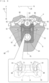
- FIG. 5 is a plan view showing the upper cover 90 being attached onto the fuel tank 8 of Fig. 4 .
- the hatching patterns that are different from each other are applied to the fuel tank 8 and the upper cover 90 in order to facilitate understanding of the shapes of the fuel tank 8 and the upper cover 90.
- the enlarged plan view showing the positional relationship among the intake port 11 of the air cleaner 10, the fuel tank 8, the tank protection member 70 and the cover opening 91 of the upper cover 90 is shown in the balloon.
- the upper cover 90 of the present example surrounds the center portion of the fuel cap 81 of the fuel tank 8 in a plan view. Further, the upper cover 90 extends in the front-and-rear direction FB between the fuel cap 81 and the key cylinder 95. The front half portion of the upper cover 90 overlaps with a portion of the air cleaner 10, a portion of the fuel tank 8 and the entire tank protection member 70 in a plan view.
- the pair of above-mentioned cover openings 91 is formed in the front half portion of the upper cover 90.
- the pair of cover openings 91 is symmetrical with respect to a vehicle central axis CL in a plan view.
- the vehicle central axis CL of Fig. 5 is a virtual straight line extending in the front-and-rear direction FB through the center of the motorcycle 100 of Fig. 1 in the left-and-right direction LR.
- Each of the pair of cover openings 91 is formed to open upwardly or obliquely upwardly and extend in the front-and-rear direction FB.
- the pair of cover openings 91 is formed such that the sum of the opening areas of the pair of cover openings 91 is equal to or smaller than the opening area of the intake port 11 of the air cleaner 10.
- the opening area of one cover opening 91 is the area of the region surrounded by the inner edge of the cover opening 91 when the one cover opening 91 is viewed in a direction in which the cover opening 91 opens. Further, the opening area of the intake port 11 is the area of the region surrounded by the inner edge of the intake port 11 when the intake port 11 is viewed in a direction in which the intake port 11 opens.
- a wire mesh 92 is provided in each cover opening 91.
- the wire mesh 92 suppresses entry of dust floating outside of the motorcycle 100 into the space below the upper cover 90 through the cover opening 91.
- each cover opening 91 of the upper cover 90 overlaps with the intake port 11 of the air cleaner 10 in a plan view.
- the region in which each cover opening 91 of the upper cover 90 and the intake port 11 of the air cleaner 10 overlap with each other in a plan view is referred to as a common opening region CR.
- Each of the fuel tank 8 and the tank protection member 70 according to the present embodiment is arranged so as to overlap with the entire common opening regions CR in a plan view. This prevents the intake port 11 of the air cleaner 10 from being exposed to the space above the upper cover 90 (outside of the motorcycle 100). Therefore, even when entering the space below the upper cover 90 from the pair of cover openings 91, droplets of rainwater or the like are prevented from further directly entering into the intake port 11 of the air cleaner 10.
- Fig. 6 is a schematic cross sectional view of the upper surface portion of the air cleaner 10 and its peripheral members taken along the line M-M of Fig. 5 .
- Fig. 7 is a schematic cross sectional view of the upper surface portion of the air cleaner 10 and its peripheral members taken along the line N-N of Fig. 6 .
- a first clearance space GS1 is formed between the air cleaner 10 and the fuel tank 8.
- the first clearance space GS1 has a height of several millimeters to several centimeters and communicates with the inner space IS of the air cleaner 10 through the intake port 11 of the air cleaner 10.
- a second clearance space GS2 is formed between the tank protection member 70 and the upper cover 90.
- the second clearance space GS2 has a height of several millimeters to several centimeters and communicates with the space above the upper cover 90 through the cover opening 91 of the upper cover 90.
- the tank protection member 70 includes the plurality of partitioning portions 74 that project upwardly.
- the second clearance space GS2 is partitioned into a plurality of spaces respectively corresponding to the pair of sound transmission portions 71, the pair of wire holding portions 72 and the coupling portion 73 of the tank protection member 70 by the plurality of partitioning portions 74.
- the harness 82 is contained in the space corresponding to the right wire holding portion 72 in the second clearance space GS2.
- the harness 82 is not contained in the space corresponding to the left wire holding portion 72 in the second clearance space GS2.
- a clearance space is formed between the fuel tank 8 and the tank protection member 70 as well as between the air cleaner 10 and the fuel tank 8 and between the tank protection member 70 and the upper cover 90.
- the clearance space between the fuel tank 8 and the tank protection member 70 is negligibly smaller than the first clearance space GS1 and the second clearance space GS2.
- the portion of the fuel tank 8 that overlaps with the intake port 11 of the air cleaner 10 in a plan view includes a tank upper surface portion 8A and a tank lower surface portion 8B.
- a fuel storage space FS for storing fuel is formed between the tank upper surface portion 8A and the tank lower surface portion 8B.
- a communication space GS3 is formed between the air cleaner 10 and the upper cover 90 at a position farther forward than the front end portion of the fuel tank 8 and the front end portion of the tank protection member 70 to cause the first clearance space GS1 and the second clearance space GS2 to communicate with each other.
- the first clearance space GS1, the second clearance space GS2 and the communication space GS3 form a continuous space that extends continuously from the intake port 11 of the air cleaner 10 to the pair of cover openings 91 of the upper cover 90 while bypassing the fuel tank 8 and the tank protection member 70.
- the continuous space functions as a sound transmission space that transmits an intake sound output upwardly from the intake port 11 of the air cleaner 10 to the pair of cover openings 91 of the upper cover 90. Therefore, during traveling of the motorcycle 100, as indicated by the thick solid arrow in Fig. 7 , the intake sound output from the intake port 11 is efficiently output upwardly of the upper cover 90 from the pair of cover openings 91 through the first clearance space GS1, the communication space GS3 and the second clearance space GS2.
- the entire cover opening 91 overlaps with the sound transmission portion 71 of the tank protection member 70 in a plan view.
- the second clearance space GS2 is partitioned into the plurality of spaces by the plurality of partitioning portions 74 of the tank protection member 70.
- the upper surface of the left sound transmission portion 71 of the tank protection member 70 is inclined so as to be directed obliquely downwardly from the right to the left. Further, the upper surface of the right sound transmission portion 71 of the tank protection member 70 is inclined so as to be directed obliquely downwardly from the left to the right. Further, as shown in Fig. 7 , the upper surfaces of the left and right sound transmission portions 71 of the tank protection member 70 are inclined so as to be directed obliquely downwardly from the rear to the front.
- the intake port 11 of the air cleaner 10 is opened upwardly. Further, at least part of the pair of cover openings 91 of the upper cover 90 overlaps with the intake port 11 of the air cleaner 10 in a plan view. Therefore, during traveling of the motorcycle 100, an intake sound generated in the intake port 11 of the air cleaner 10 is output upwardly of the upper cover 90 through at least part of the pair of cover openings 91 of the upper cover 90. Therefore, the rider easily hears the intake sound generated in the air cleaner 10.
- the fuel tank 8 and the tank protection member 70 are provided between the air cleaner 10 and the upper cover 90 so as to overlap with the entire common opening regions CR in a plan view.
- the fuel tank 8 and the tank protection member 70 receive a large portion of droplets of rainwater or the like entering from the pair of cover openings 91 of the upper cover 90, and cause the received droplets to flow to the region away from the intake port 11 of the air cleaner 10. This prevents droplets from entering the intake port 11 of the air cleaner 10.
- the fuel tank 8 has the fuel storage space FS.
- the fuel storage space FS is included in the portion of the fuel tank 8 that overlaps with the common opening region CR in a plan view.
- the fuel storage space FS functions as a sound absorber that well absorbs the sound having a specific frequency.
- it is possible to reduce the output of the sound having a specific frequency that does not conform with the preference of the rider from the pair of cover openings 91 of the upper cover 90.
- the sound absorbing function of the common opening regions CR changes according to the state of the inner space of the fuel tank 8 that overlaps with the common opening regions CR, that is, whether the fuel tank 8 is filled with fuel.
- the intake sound that is output from the pair of cover openings 91 of the upper cover 90 changes in accordance with the state in the common opening regions CR. Therefore, the rider can identify the remaining amount of fuel by hearing the intake sound.
- the fuel tank 8 and the tank protection member 70 are used as shielding members for preventing droplets entering the pair of cover openings 91 of the upper cover 90 from entering the intake port 11 of the air cleaner 10.
- the continuous space including the first clearance space GS1, the second clearance space GS2 and the communication space GS3 is formed between the air cleaner 10 and the upper cover 90.
- the air cleaner 10, the fuel tank 8, the tank protection member 70 and the upper cover 90 forming the continuous space form a so-called labyrinth structure that restricts a flow of fluid between the inner space IS of the air cleaner 10 and the space above the upper cover 90.
- the above-mentioned continuous space continuously extends from the intake port 11 to the pair of cover openings 91 while bypassing the fuel tank 8 and the tank protection member 70.
- the above-mentioned continuous space is formed in a zigzag manner in the up-and-down direction UD from the intake port 11 to the pair of cover openings 91.
- the volume of an intake sound output from the intake port 11 of the air cleaner 10 toward the first clearance space GS1 is referred to as a first sound output volume.
- the volume of an intake sound output upwardly from the pair of cover openings 91 of the upper cover 90 is referred to as a second sound output volume.
- the first sound output volume is defined in accordance with the opening area of the intake port 11 of the air cleaner 10.
- the second sound output volume is defined in accordance with the sum of the opening areas of the pair of cover openings 91 of the upper cover 90.
- the intake port 11 of the air cleaner 10 is located at a position farther upstream than the pair of cover openings 91 of the upper cover 90. Therefore, in a case in which the sum of the opening areas of the pair of cover openings 91 is larger than the opening area of the intake port 11, the volume of the output sound is defined based on not the sum of the opening areas of the pair of intake ports 11 but the opening area of the intake port 11.
- the volume of the output sound is defined in accordance with the sum of the opening areas of the pair of cover openings 91.
- the sum of the opening areas of the pair of cover openings 91 in a plan view is equal to or smaller than the opening area of the intake port 11 of the air cleaner 10 in a plan view, as described above. Therefore, after the opening area of the intake port 11 of the air cleaner 10 is set such that an amount of air to be supplied to the engine 5 is ensured, the dimensions of the pair of cover openings 91 of the upper cover 90 can be determined such that the second sound output volume is a desired sound volume.
- the pair of cover openings 91 from which an intake sound can be output is formed. Therefore, when the size and positions of the pair of cover openings 91 are defined such that a rider easily hears an intake sound, the rider can more efficiently identify the intake sound.
- the above-mentioned other member may be a member fabricated only for the purpose of reducing entry of droplets into the air cleaner 10, or may be a member that is fabricated to cover members around the key cylinder 95.
- the tank protection member 70 overlaps with at least part of the common opening region CR in a plan view.
- the tank protection member 70 overlaps with at least part of the common opening region CR in a plan view.
- tank protection member 70 While the tank protection member 70 according to the above-mentioned embodiment overlaps with the entire common opening region CR in a plan view, the present invention is not limited to this.
- the tank protection member 70 does not have to overlap with the common opening region CR in a plan view.
- the harness 82 is not provided, the tank protection member 70 does not have to be provided.
- the fuel tank 8 overlaps with at least part of the common opening region CR in a plan view.
- the fuel tank 8 and the tank protection member 70 do not at all overlap with the common opening region CR in a plan view.
- the present invention is not limited to this.
- Two or more intake ports 11 directed upwardly may be formed in the air cleaner 10.
- the pair of cover openings 91 is formed such that the sum of the opening areas of the pair of cover openings 91 is equal to or smaller than the sum of the opening areas of the plurality of intake ports 11 of the air cleaner 10.
- the plurality of partitioning portions 74 may be formed integrally with the upper cover 90 such that the second clearance space GS2 is partitioned into a plurality of spaces.
- the partitioning portions 74 may be provided in the second clearance space GS2 separately from the tank protection member 70 and the upper cover 90.
- the present invention is not limited to this.
- the present invention may be applied to another straddled vehicle such as a four-wheeled automobile, a motor tricycle or an ATV (All Terrain Vehicle).
- the engine 5 is an example of an engine
- the air cleaner 10 is an example of an air cleaner
- the upper cover 90 is an example of a cover
- the fuel tank 8 and the tank protection member 70 are examples of a shielding member
- the intake port 11 of the air cleaner 10 is an example of an intake port
- the pair of cover openings 91 of the upper cover 90 is an example of an opening.
- the common opening region CR is an example of a common opening region
- the motorcycle 100 is an example of a straddled vehicle
- the fuel tank 8 is an example of a fuel tank
- the tank protection member 70 is an example of a tank protection member
- the continuous space formed of the first clearance space GS1, the second clearance space GS2 and the communication space GS3 is an example of a sound transmission space
- the second clearance space GS2 is an example of a clearance space.
- the space in the second clearance space GS2 corresponding to the pair of sound transmission portions 71 is an example of a first space
- the space in the second clearance space GS2 corresponding to the pair of wire holding portions 72 and the coupling portion 73 is an example of a second space
- one of the pair of cover openings 91 of the upper cover 90 is an example of a first opening
- the other one of the pair of cover openings 91 of the upper cover 90 is an example of a second opening.
Landscapes
- Engineering & Computer Science (AREA)
- Mechanical Engineering (AREA)
- Chemical & Material Sciences (AREA)
- Combustion & Propulsion (AREA)
- General Engineering & Computer Science (AREA)
- Cooling, Air Intake And Gas Exhaust, And Fuel Tank Arrangements In Propulsion Units (AREA)
- Automatic Cycles, And Cycles In General (AREA)
Abstract
Description
- The present invention relates to a straddled vehicle including an engine and an air cleaner.
- An air cleaner introduces clean air into an engine. During traveling of a straddled vehicle including an engine, an intake sound may be generated from an air cleaner.
- In a case in which an intake sound generated from the air cleaner gives a rider a feeling of sprinting, the rider can enjoy driving the straddled vehicle by actively hearing the intake sound. Further, in a case in which an intake sound generated from the air cleaner changes in accordance with the work state of the engine, the rider can perform a throttle operation, a handle operation and the like while identifying the work state of the engine by actively hearing the intake sound.
-
JP 2019-172097 A - The above-mentioned side cover is located directly below a seat and relatively away from the head of the rider riding the straddled vehicle. Further, the side cover opening is formed so as to be directed sidewardly of the vehicle. Therefore, in regard to the straddled vehicle of
JP 2019-172097 A - On the other hand,
JP 2009-73287 A -
JP 2009-73287 A - An object of the present invention is to provide a straddled vehicle that enable a rider to efficiently hear an intake sound of an air cleaner while suppressing entry of a large amount of droplets into the air cleaner.
-
- (1) A straddled vehicle according to one aspect of the present invention includes an engine, an air cleaner provided above the engine, a cover provided above the air cleaner so as to overlap with at least part of the air cleaner in a plan view, and a shielding member provided between the air cleaner and the cover, wherein the air cleaner has an intake port which is formed so as to open upwardly and into which air to be supplied to the engine is introduced, the cover has an opening that is formed such that at least part of the opening overlaps with the intake port of the air cleaner in a plan view, and at least part of the shielding member overlaps with a common opening region in which the intake port of the air cleaner and the opening of the cover overlaps with each other in a plan view.
- In the straddled vehicle, the air cleaner is provided above the engine. The engine provided in the straddled vehicle is located between or in front of both feet of a rider riding the straddled vehicle. Therefore, with the above-mentioned arrangement, the air cleaner is located farther downwardly than the rider's head in a portion of the straddled vehicle that is relatively close to the rider's head.
- As described above, the intake port of the air cleaner is opened upwardly. Further, at least part of the opening of the cover overlaps with the intake port of the air cleaner in a plan view. Therefore, during the work of the engine, an intake sound generated in the intake port of the air cleaner is output upwardly of the cover through at least part of the opening of the cover. Therefore, the rider can easily hear an intake sound generated from the air cleaner.
- Further, in the above-mentioned straddled vehicle, the shielding member is provided between the air cleaner and the cover such that at least part of the shielding member overlaps with the common opening region in a plan view. In this case, the shielding member reduces further entry of droplets of rainwater or the like, which enters the opening of the cover, into the intake port of the air cleaner.
- As a result, it is possible to allow the rider to efficiently hear an intake sound of the air cleaner while suppressing entry of a large amount of droplets into the air cleaner.
- (2) At least part of the shielding member may overlap with the entire common opening region in a plan view. In this case, a large portion of droplets entering the space between the cover and the air cleaner through the opening of the cover is received by the shielding member and flows to a region away from the intake port of the air cleaner in a plan view. This prevents droplets of rainwater or the like from entering the intake port of the air cleaner.
- (3) The straddled vehicle may further include a fuel tank, wherein the shielding member may be constituted by at least part of the fuel tank.
- The fuel tank has a fuel storage space for storing fuel therein. The fuel storage space is included in the portion of the shielding member that overlaps with the common opening region in a plan view. In this case, the fuel storage space of the fuel tank functions as a sound absorber that well absorbs a sound having a specific frequency. Thus, it is possible to reduce the output of a sound having a specific frequency that does not conform with the preference of the rider from the opening of the cover.
- Further, the sound absorbing function of the fuel storage space of the fuel tank changes in accordance with the state in the fuel storage space, that is, whether the fuel storage space is filled with fuel. Thus, an intake sound output from the opening of the cover changes in accordance with the state in the fuel storage space. Therefore, the rider can identify the remaining amount of fuel by hearing an intake sound generated from the air cleaner.
- (4) The straddled vehicle may further include a fuel tank, and a tank protection member that protects the fuel tank, wherein the shielding member may be constituted by at least part of the fuel tank and the tank protection member.
- In this case, because at least part of the fuel tank and the tank protection member is used as the shielding member, it is not necessary to prepare a member for reducing entry of droplets into the air cleaner separately from the fuel tank and the tank protection member. This suppresses an increase in number of components and complication of the configuration.
- (5) A sound transmission space that is formed so as to continuously extend from the intake port of the air cleaner to the opening of the cover while bypassing the shielding member may be formed between the air cleaner and the cover.
- With the above-mentioned configuration, the cover, the air cleaner and the shielding member form a so-called labyrinth structure that restricts a flow of fluid between the space in the air cleaner and the space above the cover. Thus, the sound transmission space is formed in a zigzag manner between the opening of the cover and the intake port of the air cleaner in a predetermined vertical cross section. Therefore, even in a case in which droplets of rainwater or the like enter the space between the shielding member and the cover from the opening of the cover, further entry of the droplets into the intake port of the air cleaner is reduced. Further, an intake sound generated in the intake port of the air cleaner is output from the opening of the cover through the sound transmission space.
- (6) The sound transmission space may include a clearance space located between the cover and the shielding member, a partitioning portion that partitions the clearance space into a first space and a second space may be provided at at least one of the cover and the shielding member, the first space may be a space that communicates with a space above the cover through the opening of the cover, and the second space may be a space excluding the first space in the clearance space.
- In this case, when being propagated to the first space, part of an intake sound generated in the intake port of the air cleaner is guided to the opening of the cover without being diffused to the second space in the clearance space. Thus, the volume of the intake sound to be output from the opening of the cover is prevented from being significantly reduced.
- (7) A sum of an opening area of the opening of the cover may be equal to or smaller than a sum of an opening area of the intake port of the air cleaner.
- The volume of an intake sound output upwardly from the intake port of the air cleaner is referred to as a first sound output volume. The volume of an intake sound output upwardly from the opening of the cover is referred to as a second sound output volume. The first sound output volume is defined in accordance with the total opening area of the intake port of the air cleaner. The second sound output volume is defined in accordance with the sum of the opening area of the opening of the cover.
- In the output path of the intake sound of the air cleaner, the intake port of the air cleaner is located at a position farther upstream than the opening of the cover. Therefore, in a case in which the sum of the opening area of the opening of the cover is larger than the sum of the opening area of the intake port of the air cleaner, the volume of an output sound is defined based on not the sum of the opening area of the opening of the cover but the sum of the opening area of the intake port of the air cleaner.
- On the other hand, in a case in which the sum of the opening area of the opening of the cover is larger than the sum of the opening area of the intake port of the air cleaner, the volume of an output sound is defined in accordance with the sum of the opening area of the opening of the cover.
- Therefore, after the opening area of the intake port of the air cleaner is set such that an amount of air to be supplied to the engine is ensured, the dimension of the opening of the cover can be determined such that the second sound output volume is a desired sound volume.
- (8) The opening of the cover may include a first opening and a second opening, each of the first opening and the second opening may be formed such that at least part of each of the first opening and the second opening overlaps with the intake port of the air cleaner in a plan view, the shielding member may be configured to overlap with at least part of the first opening of the cover in a plan view and may be configured to overlap with at least part of the second opening of the cover in a plan view.
- In this case, flexibility in layout of the opening in the cover is improved. Thus, it is possible to allow a rider to identify an intake sound more efficiently by providing the first opening and the second opening in order for the rider to hear the intake sound easily.
- Other features, elements, characteristics, and advantages of the present disclosure will become more apparent from the following description of preferred embodiments of the present disclosure with reference to the attached drawings.
-
-
Fig. 1 is a side view of a motorcycle according to one embodiment of the present invention; -
Fig. 2 is a plan view of an air cleaner ofFig. 1 ; -
Fig. 3 is a plan view showing a fuel tank being provided on the air cleaner ofFig. 2 ; -
Fig. 4 is a plan view showing a tank protection member being attached to the fuel tank ofFig. 3 ; -
Fig. 5 is a plan view showing an upper cover being attached onto the fuel tank ofFig. 4 ; -
Fig. 6 is a schematic cross sectional view of an upper surface portion of the air cleaner and its peripheral members taken along the line M-M inFig. 5 ; and -
Fig. 7 is a schematic cross sectional view of the upper surface portion of the air cleaner and its peripheral members taken along the line N-N inFig. 6 . - A straddled vehicle according to one embodiment of the present invention will be described below with reference to the drawings. A motorcycle will be described as one example of the straddled vehicle.
-
Fig. 1 is a side view of amotorcycle 100 according to one embodiment of the present invention. InFig. 1 , themotorcycle 100 standing up to be perpendicular to the road surface is shown. In each ofFig. 1 and subsequent given diagrams, a front-and-rear direction FB, a left-and-right direction LR and an up-and-down direction UD of themotorcycle 100 are suitably indicated by the arrows. The direction in which the arrow is directed in the front-and-rear direction FB is referred to as forward, and its opposite direction is referred to as rearward. Further, the direction in which the arrow is directed in the left-and-right direction LR is referred to as leftward, and its opposite direction is referred to as rightward. Further, the direction in which the arrow is directed in the up-and-down direction UD is referred to as upward, and its opposite direction is referred to as downward. Further, in each ofFig. 1 and subsequent given diagrams, reference characters F, B, L, R, U and D shown together with the arrows indicating directions indicate forward, rearward, leftward, rightward, upward and downward, respectively. - The
motorcycle 100 ofFig. 1 includes a metallic body frame 1. The body frame 1 includes amain frame 1M and arear frame 1R. The front end portion of themain frame 1M constitutes a head pipe HP. Themain frame 1M is formed to extend rearwardly and downwardly from the head pipe HP. Therear frame 1R is attached to themain frame 1M so as to extend rearwardly and slightly upwardly from the rear end portion of themain frame 1M and its vicinity. - A
front fork 2 is provided at the head pipe HP to be rotatable about the center axis of the head pipe HP. A front wheel 3 is rotatably supported at the lower end portion of thefront fork 2. Ahandle 4 is provided at the upper end portion of thefront fork 2. - The
main frame 1M supports anengine 5 at a position farther downward than the head pipe HP. Anair cleaner 10 and afuel tank 8 are provided to be located upwardly of theengine 5 and rearwardly of the head pipe HP. Theair cleaner 10 and thefuel tank 8 are supported by themain frame 1M and at least part of theair cleaner 10 and thefuel tank 8 is located above themain frame 1M. - Part of the
fuel tank 8 is located above theair cleaner 10. Anupper cover 90 is attached to thefuel tank 8 so as to cover part of theair cleaner 10 and part of thefuel tank 8 from above. A pair of left andright cover openings 91 is formed in theupper cover 90. InFig. 1 , only the left cover opening 91 of the pair ofcover openings 91 is shown. Akey cylinder 95 is provided to be adjacent to the front end portion of theupper cover 90. Thekey cylinder 95 is supported at themain frame 1M. Aseat 9 is provided rearwardly of thefuel tank 8. Theseat 9 is mainly supported by therear frame 1R and located above therear frame 1R. - A
rear arm 6 is provided to extend rearwardly from a lower portion at the rear end of themain frame 1M. Therear arm 6 is supported at themain frame 1M via a pivot shaft. A rear wheel 7 is rotatably supported at the rear end portion of therear arm 6. The rear wheel 7 is rotated as a drive wheel by the motive power generated from theengine 5. - The
air cleaner 10 is mainly constituted by an air cleaner case and a filter element (not shown). The filter element is provided in the air cleaner case. During traveling of themotorcycle 100, air outside of themotorcycle 100 is guided to the inner space of the air cleaner case, and is supplied to theengine 5 while being cleaned by the filter element. - The
air cleaner 10 has an intake port 11 (seeFig. 2 , described below) into which air to be supplied to theengine 5 is introduced. When air outside of themotorcycle 100 is introduced into theintake port 11 of theair cleaner 10, an intake sound is generated. In a case in which an intake sound is an intake sound that gives a rider the feeling of sprinting, the rider can enjoy driving themotorcycle 100 by hearing the intake sound. Further, in a case in which an intake sound changes in accordance with the work state of the engine, the driver can identify the work state of the engine by hearing the intake sound. - As such, in the
motorcycle 100 according to the present embodiment, in order to allow the rider to efficiently hear an intake sound generated from theair cleaner 10, the configurations of theair cleaner 10 and its peripheral members are devised. The configurations of theair cleaner 10 and its peripheral members will be described below in detail. -
Fig. 2 is a plan view of theair cleaner 10 ofFig. 1 . InFig. 2 , theair cleaner 10 ofFig. 1 being attached to themain frame 1M is shown. Further,Fig. 2 shows thekey cylinder 95 and thehandle 4 ofFig. 1 together with theair cleaner 10. As shown inFig. 2 , theair cleaner 10 has theintake port 11. Theintake port 11 is formed so as to open upwardly. Further, theintake port 11 of the present example is located in the vicinity of the front end portion of theair cleaner 10 and extends in the left-and-right direction LR of themotorcycle 100 while having a substantially constant width in a plan view. - When the
motorcycle 100 ofFig. 1 is assembled, thefuel tank 8 is attached to themain frame 1M so as to cover a large portion of theair cleaner 10 from above with theair cleaner 10 being attached to themain frame 1M. -
Fig. 3 is a plan view showing thefuel tank 8 being provided on theair cleaner 10 ofFig. 2 . InFig. 3 , hatching is applied to thefuel tank 8 in order to facilitate understanding of the shape of thefuel tank 8. As shown inFig. 3 , thefuel tank 8 of the present example covers a large portion of theair cleaner 10 from above except for the front end portion of theair cleaner 10 in a plan view. Further, thefuel tank 8 overlaps with theentire intake port 11 of theair cleaner 10 in a plan view. Further, afuel cap 81 is provided at the substantially central portion of the upper surface of thefuel tank 8. - One end portion of a
harness 82 is connected to part of thefuel cap 81. The other end portion of theharness 82 is connected to aharness connecting portion 89 provided in the vicinity of thekey cylinder 95. Part of theharness 82 overlaps with part of thefuel tank 8 in a plan view. While being connected to thefuel cap 81 and the connectingportion 89, theharness 82 is provided with a play for ensuring easiness of attachment and detachment work and ensuring stability of the connection state. Further, theharness 82 is flexible. Therefore, during traveling of themotorcycle 100, when theharness 82 swings with theharness 82 and thefuel tank 8 being in contact with each other, part of the surface of thefuel tank 8 may wear due to the contact with theharness 82. - As such, in the present embodiment, a tank protection member 70 (see
Fig. 4 , described below) is attached to thefuel tank 8 in order to prevent the contact between thefuel tank 8 and theharness 82. Thetank protection member 70 covers part of the upper surface of thefuel tank 8. -
Fig. 4 is a plan view showing thetank protection member 70 being attached to thefuel tank 8 ofFig. 3 . InFig. 4 , in order to facilitate understanding of the shapes of thefuel tank 8 and thetank protection member 70, hatching is applied to thefuel tank 8, and a dotted pattern is applied to thetank protection member 70. Further, inFig. 4 , an enlarged plan view of thetank protection member 70 is shown in the balloon. - As shown in
Fig. 4 , thetank protection member 70 of the present example is provided so as to overlap with a portion of the upper surface of thefuel tank 8 located forwardly of thefuel cap 81 and be located between thefuel tank 8 and theharness 82 in a plan view. - Further, the
tank protection member 70 is a substantially plate-shaped single member formed of resin having relatively high rigidity, and has a pair of left and rightsound transmission portions 71, a pair of left and rightwire holding portions 72 and acoupling portion 73. The pair ofwire holding portions 72 is arranged at the left and right of thecoupling portion 73. Eachwire holding portion 72 is adjacent to thecoupling portion 73. The pair ofsound transmission portions 71 are arranged at the left and right of the pair ofwire holding portions 72. The rightsound transmission portion 71 is adjacent to the rightwire holding portion 72, and the leftsound transmission portion 71 is adjacent to the leftwire holding portion 72. - The pair of
sound transmission portions 71, the pair ofwire holding portions 72 and thecoupling portion 73 of the present example have substantially flat upper surfaces. The upper surface of each of the pair ofsound transmission portions 71, the pair ofwiring holding portions 72 and thecoupling portion 73 may have a mildly bent shape or a mildly curved shape. - In the
tank protection member 70, apartitioning portion 74 is formed at the left edge portion of the leftsound transmission portion 71. A partitioningportion 74 is also formed between the leftsound transmission portion 71 and the leftwire holding portion 72. A partitioningportion 74 is also formed between the leftwire holding portion 72 and thecoupling portion 73. A partitioningportion 74 is also formed between thecoupling portion 73 and the rightwire holding portion 72. A partitioningportion 74 is also formed between the rightwire holding portion 72 and the leftsound transmission portion 71. Further, apartitioning portion 74 is formed at the right edge portion of the rightsound transmission portion 71. - Each partitioning
portion 74 is formed so as to project upwardly from the upper surfaces of the pair ofsound transmission portions 71, the pair ofwire holding portions 72 and thecoupling portion 73 by a predetermined height and extend in the front-and-rear direction FB. Thus, in thetank protection member 70, a plurality of groove portions that open upwardly and extend in the front-and-rear direction FB with the pair ofsound transmission portions 71, the pair ofwire holding portions 72 and thecoupling portion 73 as bottom portions are formed. - With the
tank protection member 70 attached to thefuel tank 8, part of the above-mentionedharness 82 is contained in the groove portion having the rightwire holding portion 72 of thetank protection member 70 as the bottom portion. Further, thetank protection member 70 overlaps with a large portion of theintake port 11 of theair cleaner 10 in a plan view. Further, the pair ofsound transmission portions 71 of thetank protection member 70 extends in the front-and-rear direction FB so as to cross theintake port 11 extending in the left-and-right direction LR in a plan view. - The
upper cover 90 ofFig. 1 is attached onto thefuel tank 8 to which thetank protection member 70 is attached.Fig. 5 is a plan view showing theupper cover 90 being attached onto thefuel tank 8 ofFig. 4 . InFig. 5 , the hatching patterns that are different from each other are applied to thefuel tank 8 and theupper cover 90 in order to facilitate understanding of the shapes of thefuel tank 8 and theupper cover 90. Further, inFig. 5 , the enlarged plan view showing the positional relationship among theintake port 11 of theair cleaner 10, thefuel tank 8, thetank protection member 70 and the cover opening 91 of theupper cover 90 is shown in the balloon. - As shown in
Fig. 5 , theupper cover 90 of the present example surrounds the center portion of thefuel cap 81 of thefuel tank 8 in a plan view. Further, theupper cover 90 extends in the front-and-rear direction FB between thefuel cap 81 and thekey cylinder 95. The front half portion of theupper cover 90 overlaps with a portion of theair cleaner 10, a portion of thefuel tank 8 and the entiretank protection member 70 in a plan view. - The pair of above-mentioned
cover openings 91 is formed in the front half portion of theupper cover 90. The pair ofcover openings 91 is symmetrical with respect to a vehicle central axis CL in a plan view. The vehicle central axis CL ofFig. 5 is a virtual straight line extending in the front-and-rear direction FB through the center of themotorcycle 100 ofFig. 1 in the left-and-right direction LR. Each of the pair ofcover openings 91 is formed to open upwardly or obliquely upwardly and extend in the front-and-rear direction FB. In the present embodiment, the pair ofcover openings 91 is formed such that the sum of the opening areas of the pair ofcover openings 91 is equal to or smaller than the opening area of theintake port 11 of theair cleaner 10. - The opening area of one
cover opening 91 is the area of the region surrounded by the inner edge of thecover opening 91 when the onecover opening 91 is viewed in a direction in which thecover opening 91 opens. Further, the opening area of theintake port 11 is the area of the region surrounded by the inner edge of theintake port 11 when theintake port 11 is viewed in a direction in which theintake port 11 opens. - A
wire mesh 92 is provided in eachcover opening 91. Thewire mesh 92 suppresses entry of dust floating outside of themotorcycle 100 into the space below theupper cover 90 through thecover opening 91. - As shown in the balloon of
Fig. 5 , part of each cover opening 91 of theupper cover 90 overlaps with theintake port 11 of theair cleaner 10 in a plan view. Here, the region in which each cover opening 91 of theupper cover 90 and theintake port 11 of theair cleaner 10 overlap with each other in a plan view is referred to as a common opening region CR. - Each of the
fuel tank 8 and thetank protection member 70 according to the present embodiment is arranged so as to overlap with the entire common opening regions CR in a plan view. This prevents theintake port 11 of theair cleaner 10 from being exposed to the space above the upper cover 90 (outside of the motorcycle 100). Therefore, even when entering the space below theupper cover 90 from the pair ofcover openings 91, droplets of rainwater or the like are prevented from further directly entering into theintake port 11 of theair cleaner 10. -
Fig. 6 is a schematic cross sectional view of the upper surface portion of theair cleaner 10 and its peripheral members taken along the line M-M ofFig. 5 .Fig. 7 is a schematic cross sectional view of the upper surface portion of theair cleaner 10 and its peripheral members taken along the line N-N ofFig. 6 . As shown inFig. 6 , a first clearance space GS1 is formed between theair cleaner 10 and thefuel tank 8. The first clearance space GS1 has a height of several millimeters to several centimeters and communicates with the inner space IS of theair cleaner 10 through theintake port 11 of theair cleaner 10. - On the other hand, a second clearance space GS2 is formed between the
tank protection member 70 and theupper cover 90. The second clearance space GS2 has a height of several millimeters to several centimeters and communicates with the space above theupper cover 90 through the cover opening 91 of theupper cover 90. - As described above, the
tank protection member 70 includes the plurality ofpartitioning portions 74 that project upwardly. Thus, the second clearance space GS2 is partitioned into a plurality of spaces respectively corresponding to the pair ofsound transmission portions 71, the pair ofwire holding portions 72 and thecoupling portion 73 of thetank protection member 70 by the plurality ofpartitioning portions 74. In the present example, as described above, theharness 82 is contained in the space corresponding to the rightwire holding portion 72 in the second clearance space GS2. Theharness 82 is not contained in the space corresponding to the leftwire holding portion 72 in the second clearance space GS2. - A clearance space is formed between the
fuel tank 8 and thetank protection member 70 as well as between theair cleaner 10 and thefuel tank 8 and between thetank protection member 70 and theupper cover 90. However, the clearance space between thefuel tank 8 and thetank protection member 70 is negligibly smaller than the first clearance space GS1 and the second clearance space GS2. - The portion of the
fuel tank 8 that overlaps with theintake port 11 of theair cleaner 10 in a plan view includes a tankupper surface portion 8A and a tanklower surface portion 8B. A fuel storage space FS for storing fuel is formed between the tankupper surface portion 8A and the tanklower surface portion 8B. - As shown in
Fig. 7 , a communication space GS3 is formed between theair cleaner 10 and theupper cover 90 at a position farther forward than the front end portion of thefuel tank 8 and the front end portion of thetank protection member 70 to cause the first clearance space GS1 and the second clearance space GS2 to communicate with each other. - The first clearance space GS1, the second clearance space GS2 and the communication space GS3 form a continuous space that extends continuously from the
intake port 11 of theair cleaner 10 to the pair ofcover openings 91 of theupper cover 90 while bypassing thefuel tank 8 and thetank protection member 70. The continuous space functions as a sound transmission space that transmits an intake sound output upwardly from theintake port 11 of theair cleaner 10 to the pair ofcover openings 91 of theupper cover 90. Therefore, during traveling of themotorcycle 100, as indicated by the thick solid arrow inFig. 7 , the intake sound output from theintake port 11 is efficiently output upwardly of theupper cover 90 from the pair ofcover openings 91 through the first clearance space GS1, the communication space GS3 and the second clearance space GS2. - Here, as shown in
Figs. 5 and6 , in regard to each of the pair ofcover openings 91 of theupper cover 90, the entire cover opening 91 overlaps with thesound transmission portion 71 of thetank protection member 70 in a plan view. Further, as described above, the second clearance space GS2 is partitioned into the plurality of spaces by the plurality ofpartitioning portions 74 of thetank protection member 70. - In this case, when being propagated to the space corresponding to the pair of
sound transmission portions 71 of thetank protection member 70 in the second clearance space GS2, part of an intake sound is guided to the pair ofcover openings 91 of theupper cover 90 without being diffused in the second clearance space GS2. Thus, the volume of the intake sound output from the pair ofcover openings 91 of theupper cover 90 is prevented from being significantly reduced. - In particular, in the above-mentioned
tank protection member 70, the distance between the twopartitioning portions 74 for partitioning the space corresponding to each of the pair ofsound transmission portions 71, in the left-and-right direction LR, gradually decreases rearwardly from the front end portion of the tank protection member 70 (see the plan view in the balloon ofFig. 4 ). Therefore, in the second clearance space GS2, the twopartitioning portions 74 forming the space corresponding to each of the pair ofsound transmission portions 71 collect a sound transmitted from the first clearance space GS1 through the communication space GS3 in thecover opening 91. Thus, in thecover opening 91, an intake sound is output more efficiently. - As shown in
Fig. 6 , the upper surface of the leftsound transmission portion 71 of thetank protection member 70 is inclined so as to be directed obliquely downwardly from the right to the left. Further, the upper surface of the rightsound transmission portion 71 of thetank protection member 70 is inclined so as to be directed obliquely downwardly from the left to the right. Further, as shown inFig. 7 , the upper surfaces of the left and rightsound transmission portions 71 of thetank protection member 70 are inclined so as to be directed obliquely downwardly from the rear to the front. With such a configuration, even in a case in which droplets enter the second clearance space GS2 through thecover opening 91, the entered droplets are smoothly guided to a region away from theintake port 11 via thesound transmission portion 71, as indicated by the thick two-dots and dash arrow inFig. 7 . -
- (a) As described above, in the
motorcycle 100 according to the present embodiment, theair cleaner 10 is provided above theengine 5. Theengine 5 is located between or in front of both feet of a rider riding themotorcycle 100. Therefore, with the above-mentioned arrangement, theair cleaner 10 is located at a position relatively close to and lower than the rider's head in themotorcycle 100. - The
intake port 11 of theair cleaner 10 is opened upwardly. Further, at least part of the pair ofcover openings 91 of theupper cover 90 overlaps with theintake port 11 of theair cleaner 10 in a plan view. Therefore, during traveling of themotorcycle 100, an intake sound generated in theintake port 11 of theair cleaner 10 is output upwardly of theupper cover 90 through at least part of the pair ofcover openings 91 of theupper cover 90. Therefore, the rider easily hears the intake sound generated in theair cleaner 10. - Further, in the above-mentioned
motorcycle 100, thefuel tank 8 and thetank protection member 70 are provided between theair cleaner 10 and theupper cover 90 so as to overlap with the entire common opening regions CR in a plan view. In this case, thefuel tank 8 and thetank protection member 70 receive a large portion of droplets of rainwater or the like entering from the pair ofcover openings 91 of theupper cover 90, and cause the received droplets to flow to the region away from theintake port 11 of theair cleaner 10. This prevents droplets from entering theintake port 11 of theair cleaner 10. - As a result, it is possible to allow the rider to efficiently hear the intake sound of the
air cleaner 10 while suppressing entry of a large amount of droplets into theair cleaner 10. - (b) As described above, the
fuel tank 8 has the fuel storage space FS. The fuel storage space FS is included in the portion of thefuel tank 8 that overlaps with the common opening region CR in a plan view. In this case, the fuel storage space FS functions as a sound absorber that well absorbs the sound having a specific frequency. Thus, it is possible to reduce the output of the sound having a specific frequency that does not conform with the preference of the rider from the pair ofcover openings 91 of theupper cover 90. - Further, the sound absorbing function of the common opening regions CR changes according to the state of the inner space of the
fuel tank 8 that overlaps with the common opening regions CR, that is, whether thefuel tank 8 is filled with fuel. Thus, the intake sound that is output from the pair ofcover openings 91 of theupper cover 90 changes in accordance with the state in the common opening regions CR. Therefore, the rider can identify the remaining amount of fuel by hearing the intake sound. - (c) As described above, the
fuel tank 8 and thetank protection member 70 are used as shielding members for preventing droplets entering the pair ofcover openings 91 of theupper cover 90 from entering theintake port 11 of theair cleaner 10. Thus, it is not necessary to prepare a member for reducing the entry of droplets into theair cleaner 10 separately from thefuel tank 8 and thetank protection member 70. This suppresses an increase in number of components and complication of the configuration. - (d) As described above, the continuous space including the first clearance space GS1, the second clearance space GS2 and the communication space GS3 is formed between the
air cleaner 10 and theupper cover 90. Theair cleaner 10, thefuel tank 8, thetank protection member 70 and theupper cover 90 forming the continuous space form a so-called labyrinth structure that restricts a flow of fluid between the inner space IS of theair cleaner 10 and the space above theupper cover 90. Thus, the above-mentioned continuous space continuously extends from theintake port 11 to the pair ofcover openings 91 while bypassing thefuel tank 8 and thetank protection member 70. In other words, the above-mentioned continuous space is formed in a zigzag manner in the up-and-down direction UD from theintake port 11 to the pair ofcover openings 91. - Therefore, even in a case in which droplets of rain water or the like enter the pair of
cover openings 91 of theupper cover 90, further entry of the droplets into theintake port 11 of theair cleaner 10 is reduced. Further, an intake sound generated in theintake port 11 of theair cleaner 10 is output from the pair ofcover openings 91 of theupper cover 90. - (e) The volume of an intake sound output from the
intake port 11 of theair cleaner 10 toward the first clearance space GS1 is referred to as a first sound output volume. Further, the volume of an intake sound output upwardly from the pair ofcover openings 91 of theupper cover 90 is referred to as a second sound output volume. The first sound output volume is defined in accordance with the opening area of theintake port 11 of theair cleaner 10. The second sound output volume is defined in accordance with the sum of the opening areas of the pair ofcover openings 91 of theupper cover 90. - In the output path of an intake sound of the
air cleaner 10, theintake port 11 of theair cleaner 10 is located at a position farther upstream than the pair ofcover openings 91 of theupper cover 90. Therefore, in a case in which the sum of the opening areas of the pair ofcover openings 91 is larger than the opening area of theintake port 11, the volume of the output sound is defined based on not the sum of the opening areas of the pair ofintake ports 11 but the opening area of theintake port 11. - On the other hand, in a case in which the sum of the opening areas of the pair of
cover openings 91 is equal to or smaller than the opening area of theintake port 11, the volume of the output sound is defined in accordance with the sum of the opening areas of the pair ofcover openings 91. - In the
motorcycle 100 according to the present embodiment, the sum of the opening areas of the pair ofcover openings 91 in a plan view is equal to or smaller than the opening area of theintake port 11 of theair cleaner 10 in a plan view, as described above. Therefore, after the opening area of theintake port 11 of theair cleaner 10 is set such that an amount of air to be supplied to theengine 5 is ensured, the dimensions of the pair ofcover openings 91 of theupper cover 90 can be determined such that the second sound output volume is a desired sound volume. - (f) In the
upper cover 90 according to the present embodiment, the pair ofcover openings 91 from which an intake sound can be output is formed. Therefore, when the size and positions of the pair ofcover openings 91 are defined such that a rider easily hears an intake sound, the rider can more efficiently identify the intake sound. -
- (a) While each of the
fuel tank 8 and thetank protection member 70 according to the above-mentioned embodiment overlaps with the entire common opening region CR in a plan view, the present invention is not limited to this. Each of thefuel tank 8 and thetank protection member 70 may overlap with part of the common opening region CR. Also in this case, it is possible to reduce entry of droplets such as rainwater into theair cleaner 10 from theintake port 11 as compared to a case in which each of thefuel tank 8 and thetank protection member 70 does not at all overlap with the common opening region CR in a plan view. - (b) While each of the
fuel tank 8 and thetank protection member 70 according to the above-mentioned embodiment overlaps with the entire common opening region CR in a plan view, the present invention is not limited to this. In a case in which another member that overlaps with at least part of the common opening region CR in a plan view is present, each of thefuel tank 8 and thetank protection member 70 does not have to overlap with the common opening region CR. In this case, because the other member overlaps with at least part of the common opening region CR in a plan view, it is possible to reduce entry of droplets of rainwater or the like into theair cleaner 10 from theintake port 11 as compared to a case in which the entire common opening region CR is opened upwardly. - The above-mentioned other member may be a member fabricated only for the purpose of reducing entry of droplets into the
air cleaner 10, or may be a member that is fabricated to cover members around thekey cylinder 95. - (c) While the
fuel tank 8 according to the above-mentioned embodiment overlaps with the entire common opening region CR in a plan view, the present invention is not limited to this. Thefuel tank 8 does not have to overlap with the common opening region CR in a plan view. - Also in this case, the
tank protection member 70 overlaps with at least part of the common opening region CR in a plan view. Thus, it is possible to reduce entry of droplets of rainwater or the like into theair cleaner 10 from theintake port 11 as compared to a case in which thefuel tank 8 and thetank protection member 70 do not at all overlap with the common opening region CR in a plan view. - (d) While the
tank protection member 70 according to the above-mentioned embodiment overlaps with the entire common opening region CR in a plan view, the present invention is not limited to this. Thetank protection member 70 does not have to overlap with the common opening region CR in a plan view. Alternatively, in a case in which theharness 82 is not provided, thetank protection member 70 does not have to be provided. - Also in these cases, the
fuel tank 8 overlaps with at least part of the common opening region CR in a plan view. Thus, it is possible to reduce entry of droplets of rainwater or the like into theair cleaner 10 from theintake port 11 as compared to a case in which thefuel tank 8 and thetank protection member 70 do not at all overlap with the common opening region CR in a plan view. - (e) While the pair of
cover openings 91 is formed in theupper cover 90 according to the above-mentioned embodiment, the present invention is not limited to this. Only onecover opening 91 may be formed in theupper cover 90. - (f) While the only one
intake port 11 is formed in theair cleaner 10 according to the above-mentioned embodiment, the present invention is not limited to this. Two ormore intake ports 11 directed upwardly may be formed in theair cleaner 10. In this case, the pair ofcover openings 91 is formed such that the sum of the opening areas of the pair ofcover openings 91 is equal to or smaller than the sum of the opening areas of the plurality ofintake ports 11 of theair cleaner 10. - (g) While the plurality of
partitioning portions 74 are formed in thetank protection member 70 according to the above-mentioned embodiment, the present invention is not limited to this. The plurality ofpartitioning portions 74 do not have to be formed in thetank protection member 70. - In this case, the plurality of
partitioning portions 74 may be formed integrally with theupper cover 90 such that the second clearance space GS2 is partitioned into a plurality of spaces. Alternatively, thepartitioning portions 74 may be provided in the second clearance space GS2 separately from thetank protection member 70 and theupper cover 90. - (h) While the above-mentioned embodiment is an example in which the present invention is applied to a motorcycle, the present invention is not limited to this. The present invention may be applied to another straddled vehicle such as a four-wheeled automobile, a motor tricycle or an ATV (All Terrain Vehicle).
- In the following paragraphs, non-limiting examples of correspondences between various elements recited in the claims below and those described above with respect to various preferred embodiments of the present disclosure are explained.
- In the above-mentioned embodiment, the
engine 5 is an example of an engine, theair cleaner 10 is an example of an air cleaner, theupper cover 90 is an example of a cover, thefuel tank 8 and thetank protection member 70 are examples of a shielding member, theintake port 11 of theair cleaner 10 is an example of an intake port, and the pair ofcover openings 91 of theupper cover 90 is an example of an opening. - Further, the common opening region CR is an example of a common opening region, the
motorcycle 100 is an example of a straddled vehicle, thefuel tank 8 is an example of a fuel tank, thetank protection member 70 is an example of a tank protection member, the continuous space formed of the first clearance space GS1, the second clearance space GS2 and the communication space GS3 is an example of a sound transmission space, and the second clearance space GS2 is an example of a clearance space. - Further, the space in the second clearance space GS2 corresponding to the pair of
sound transmission portions 71 is an example of a first space, the space in the second clearance space GS2 corresponding to the pair ofwire holding portions 72 and thecoupling portion 73 is an example of a second space, one of the pair ofcover openings 91 of theupper cover 90 is an example of a first opening, and the other one of the pair ofcover openings 91 of theupper cover 90 is an example of a second opening. - As each of constituent elements recited in the claims, various other elements having configurations or functions described in the claims can be also used.
- While preferred embodiments of the present disclosure have been described above, it is to be understood that variations and modifications will be apparent to those skilled in the art without departing the scope and spirit of the present disclosure. The scope of the present disclosure, therefore, is to be determined solely by the following claims.
Claims (8)
- A straddled vehicle (100) comprising:an engine (5);an air cleaner (10) provided above the engine (5);a cover (90) provided above the air cleaner (10) so as to overlap with at least part of the air cleaner (10) in a plan view; anda shielding member (8, 70) provided between the air cleaner (10) and the cover (90), whereinthe air cleaner (10) has an intake port (11) which is formed so as to open upwardly and into which air to be supplied to the engine (5) is introduced,the cover (90) has an opening (91) that is formed such that at least part of the opening (91) overlaps with the intake port (11) of the air cleaner (10) in a plan view, andat least part of the shielding member (8, 70) overlaps with a common opening region (CR) in which the intake port (11) of the air cleaner (10) and the opening (91) of the cover overlaps (90) with each other in a plan view.
- The straddled vehicle according to claim 1, wherein
at least part of the shielding member (8, 70) overlaps with the entire common opening region (CR) in a plan view. - The straddled vehicle according to claim 1 or 2, further comprising a fuel tank (8), wherein
the shielding member (8, 70) is constituted by at least part of the fuel tank (8). - The straddled vehicle according to claim 1 or 2, further comprising:a fuel tank (8); anda tank protection member (70) that protects the fuel tank (8), whereinthe shielding member (8, 70) is constituted by at least part of the fuel tank (8) and the tank protection member (70).
- The straddled vehicle according to any one of claims 1 to 4, wherein
a sound transmission space (GS1, GS2, GS3) that is formed so as to continuously extend from the intake port (11) of the air cleaner (10) to the opening (91) of the cover (90) while bypassing the shielding member (8, 70) is formed between the air cleaner (10) and the cover (90). - The straddled vehicle according to claim 5, whereinthe sound transmission space (GS1, GS2, GS3) includes a clearance space (GS2) located between the cover (90) and the shielding member (8, 70),a partitioning portion (74) that partitions the clearance space (GS2) into a first space and a second space is provided at at least one (90) of the cover (90) and the shielding member (8, 70),the first space is a space that communicates with a space above the cover (90) through the opening (91) of the cover (90), andthe second space is a space excluding the first space in the clearance space (GS2).
- The straddled vehicle according to any one of claims 1 to 6, wherein
a sum of an opening area of the opening (91) of the cover (90) is equal to or smaller than a sum of an opening area of the intake port (11) of the air cleaner (10). - The straddled vehicle according to any one of claims 1 to 7, whereinthe opening (91) of the cover includes a first opening and a second opening (91),each of the first opening and the second opening (91) is formed such that at least part of each of the first opening (91) and the second opening overlaps (91) with the intake port (11) of the air cleaner (10) in a plan view,the shielding member (8, 70) is configured to overlap with at least part of the first opening (91) of the cover (90) in a plan view and is configured to overlap with at least part of the second opening (91) of the cover (90) in a plan view.
Applications Claiming Priority (1)
| Application Number | Priority Date | Filing Date | Title |
|---|---|---|---|
| JP2022073621A JP2023162910A (en) | 2022-04-27 | 2022-04-27 | saddle type vehicle |
Publications (2)
| Publication Number | Publication Date |
|---|---|
| EP4269778A1 true EP4269778A1 (en) | 2023-11-01 |
| EP4269778B1 EP4269778B1 (en) | 2025-03-26 |
Family
ID=85781915
Family Applications (1)
| Application Number | Title | Priority Date | Filing Date |
|---|---|---|---|
| EP23164946.8A Active EP4269778B1 (en) | 2022-04-27 | 2023-03-29 | Straddled vehicle |
Country Status (2)
| Country | Link |
|---|---|
| EP (1) | EP4269778B1 (en) |
| JP (1) | JP2023162910A (en) |
Citations (3)
| Publication number | Priority date | Publication date | Assignee | Title |
|---|---|---|---|---|
| JPH06299920A (en) * | 1993-04-17 | 1994-10-25 | Honda Motor Co Ltd | Intake device for motorcycles |
| JP2009073287A (en) | 2007-09-19 | 2009-04-09 | Honda Motor Co Ltd | Motorcycle |
| JP2019172097A (en) | 2018-03-28 | 2019-10-10 | 本田技研工業株式会社 | Air intake part structure of saddle riding type vehicle |
-
2022
- 2022-04-27 JP JP2022073621A patent/JP2023162910A/en active Pending
-
2023
- 2023-03-29 EP EP23164946.8A patent/EP4269778B1/en active Active
Patent Citations (3)
| Publication number | Priority date | Publication date | Assignee | Title |
|---|---|---|---|---|
| JPH06299920A (en) * | 1993-04-17 | 1994-10-25 | Honda Motor Co Ltd | Intake device for motorcycles |
| JP2009073287A (en) | 2007-09-19 | 2009-04-09 | Honda Motor Co Ltd | Motorcycle |
| JP2019172097A (en) | 2018-03-28 | 2019-10-10 | 本田技研工業株式会社 | Air intake part structure of saddle riding type vehicle |
Also Published As
| Publication number | Publication date |
|---|---|
| JP2023162910A (en) | 2023-11-09 |
| EP4269778B1 (en) | 2025-03-26 |
Similar Documents
| Publication | Publication Date | Title |
|---|---|---|
| CN101797943B (en) | Air guide structure of motorcycle | |
| CN110318921B (en) | Air intake structure for saddle-ride type vehicle | |
| EP1520968A1 (en) | Exhaust control device of motorcycle | |
| US7635140B2 (en) | Fender structure for motorcycle | |
| US8037958B2 (en) | Layout of compact all terrain vehicle for fuel tank, intake duct, and exhaust duct positioning | |
| CN101172504B (en) | motorcycle | |
| EP2889209B1 (en) | Front cover structure for a motorcycle | |
| CN103359225B (en) | Straddle riding type vehicle | |
| JP4574415B2 (en) | Saddle riding vehicle | |
| JP2010215214A (en) | Scooter type vehicle | |
| EP4269778B1 (en) | Straddled vehicle | |
| EP4112430A1 (en) | Saddle-type vehicle | |
| US7140462B2 (en) | Supplemental air cleaner for an all-terrain vehicle, and all-terrain vehicle incorporating same | |
| CN104010931B (en) | Straddle type vehicle | |
| JP4802727B2 (en) | Rough terrain vehicle | |
| JP7480200B2 (en) | Saddle type vehicle | |
| KR100891781B1 (en) | Cooling structure for continous variable transmission of motorcycle | |
| JP7606500B2 (en) | Saddle-type vehicle | |
| EP4372224B1 (en) | Straddled vehicle | |
| JP7682238B2 (en) | Saddle-type vehicle | |
| JP7692970B2 (en) | Saddle-type vehicle | |
| CN219544976U (en) | Saddle-type vehicle | |
| JP7773626B2 (en) | Intake structure of an internal combustion engine in a straddle-type vehicle | |
| JP7470723B2 (en) | Saddle type vehicle | |
| CN217893104U (en) | windshield |
Legal Events
| Date | Code | Title | Description |
|---|---|---|---|
| PUAI | Public reference made under article 153(3) epc to a published international application that has entered the european phase |
Free format text: ORIGINAL CODE: 0009012 |
|
| STAA | Information on the status of an ep patent application or granted ep patent |
Free format text: STATUS: REQUEST FOR EXAMINATION WAS MADE |
|
| 17P | Request for examination filed |
Effective date: 20230329 |
|
| AK | Designated contracting states |
Kind code of ref document: A1 Designated state(s): AL AT BE BG CH CY CZ DE DK EE ES FI FR GB GR HR HU IE IS IT LI LT LU LV MC ME MK MT NL NO PL PT RO RS SE SI SK SM TR |
|
| STAA | Information on the status of an ep patent application or granted ep patent |
Free format text: STATUS: EXAMINATION IS IN PROGRESS |
|
| 17Q | First examination report despatched |
Effective date: 20240527 |
|
| REG | Reference to a national code |
Ref country code: DE Ref legal event code: R079 Free format text: PREVIOUS MAIN CLASS: F02M0035100000 Ipc: F02M0035120000 Ref document number: 602023002537 Country of ref document: DE |
|
| GRAP | Despatch of communication of intention to grant a patent |
Free format text: ORIGINAL CODE: EPIDOSNIGR1 |
|
| STAA | Information on the status of an ep patent application or granted ep patent |
Free format text: STATUS: GRANT OF PATENT IS INTENDED |
|
| RIC1 | Information provided on ipc code assigned before grant |
Ipc: B62K 11/04 20060101ALI20240930BHEP Ipc: B62J 40/00 20200101ALI20240930BHEP Ipc: B62J 35/00 20060101ALI20240930BHEP Ipc: F02M 35/16 20060101ALI20240930BHEP Ipc: F02M 35/10 20060101ALI20240930BHEP Ipc: F02M 35/12 20060101AFI20240930BHEP |
|
| INTG | Intention to grant announced |
Effective date: 20241017 |
|
| P01 | Opt-out of the competence of the unified patent court (upc) registered |
Free format text: CASE NUMBER: APP_63361/2024 Effective date: 20241128 |
|
| GRAS | Grant fee paid |
Free format text: ORIGINAL CODE: EPIDOSNIGR3 |
|
| GRAA | (expected) grant |
Free format text: ORIGINAL CODE: 0009210 |
|
| STAA | Information on the status of an ep patent application or granted ep patent |
Free format text: STATUS: THE PATENT HAS BEEN GRANTED |
|
| AK | Designated contracting states |
Kind code of ref document: B1 Designated state(s): AL AT BE BG CH CY CZ DE DK EE ES FI FR GB GR HR HU IE IS IT LI LT LU LV MC ME MK MT NL NO PL PT RO RS SE SI SK SM TR |
|
| REG | Reference to a national code |
Ref country code: GB Ref legal event code: FG4D |
|
| REG | Reference to a national code |
Ref country code: CH Ref legal event code: EP |
|
| REG | Reference to a national code |
Ref country code: DE Ref legal event code: R096 Ref document number: 602023002537 Country of ref document: DE |
|
| REG | Reference to a national code |
Ref country code: IE Ref legal event code: FG4D |
|
| PGFP | Annual fee paid to national office [announced via postgrant information from national office to epo] |
Ref country code: AT Payment date: 20250417 Year of fee payment: 3 |
|
| PG25 | Lapsed in a contracting state [announced via postgrant information from national office to epo] |
Ref country code: RS Free format text: LAPSE BECAUSE OF FAILURE TO SUBMIT A TRANSLATION OF THE DESCRIPTION OR TO PAY THE FEE WITHIN THE PRESCRIBED TIME-LIMIT Effective date: 20250626 |
|
| PG25 | Lapsed in a contracting state [announced via postgrant information from national office to epo] |
Ref country code: FI Free format text: LAPSE BECAUSE OF FAILURE TO SUBMIT A TRANSLATION OF THE DESCRIPTION OR TO PAY THE FEE WITHIN THE PRESCRIBED TIME-LIMIT Effective date: 20250326 |
|
| REG | Reference to a national code |
Ref country code: LT Ref legal event code: MG9D |
|
| PG25 | Lapsed in a contracting state [announced via postgrant information from national office to epo] |
Ref country code: NO Free format text: LAPSE BECAUSE OF FAILURE TO SUBMIT A TRANSLATION OF THE DESCRIPTION OR TO PAY THE FEE WITHIN THE PRESCRIBED TIME-LIMIT Effective date: 20250626 |
|
| PGFP | Annual fee paid to national office [announced via postgrant information from national office to epo] |
Ref country code: IT Payment date: 20250331 Year of fee payment: 3 |
|
| PG25 | Lapsed in a contracting state [announced via postgrant information from national office to epo] |
Ref country code: HR Free format text: LAPSE BECAUSE OF FAILURE TO SUBMIT A TRANSLATION OF THE DESCRIPTION OR TO PAY THE FEE WITHIN THE PRESCRIBED TIME-LIMIT Effective date: 20250326 |
|
| PG25 | Lapsed in a contracting state [announced via postgrant information from national office to epo] |
Ref country code: LV Free format text: LAPSE BECAUSE OF FAILURE TO SUBMIT A TRANSLATION OF THE DESCRIPTION OR TO PAY THE FEE WITHIN THE PRESCRIBED TIME-LIMIT Effective date: 20250326 |
|
| PGFP | Annual fee paid to national office [announced via postgrant information from national office to epo] |
Ref country code: FR Payment date: 20250528 Year of fee payment: 4 |
|
| PG25 | Lapsed in a contracting state [announced via postgrant information from national office to epo] |
Ref country code: GR Free format text: LAPSE BECAUSE OF FAILURE TO SUBMIT A TRANSLATION OF THE DESCRIPTION OR TO PAY THE FEE WITHIN THE PRESCRIBED TIME-LIMIT Effective date: 20250627 Ref country code: BG Free format text: LAPSE BECAUSE OF FAILURE TO SUBMIT A TRANSLATION OF THE DESCRIPTION OR TO PAY THE FEE WITHIN THE PRESCRIBED TIME-LIMIT Effective date: 20250326 |
|
| REG | Reference to a national code |
Ref country code: NL Ref legal event code: MP Effective date: 20250326 |
|
| PG25 | Lapsed in a contracting state [announced via postgrant information from national office to epo] |
Ref country code: NL Free format text: LAPSE BECAUSE OF FAILURE TO SUBMIT A TRANSLATION OF THE DESCRIPTION OR TO PAY THE FEE WITHIN THE PRESCRIBED TIME-LIMIT Effective date: 20250326 |
|
| PG25 | Lapsed in a contracting state [announced via postgrant information from national office to epo] |
Ref country code: SE Free format text: LAPSE BECAUSE OF FAILURE TO SUBMIT A TRANSLATION OF THE DESCRIPTION OR TO PAY THE FEE WITHIN THE PRESCRIBED TIME-LIMIT Effective date: 20250326 |
|
| REG | Reference to a national code |
Ref country code: AT Ref legal event code: MK05 Ref document number: 1779190 Country of ref document: AT Kind code of ref document: T Effective date: 20250326 |
|
| PG25 | Lapsed in a contracting state [announced via postgrant information from national office to epo] |
Ref country code: SM Free format text: LAPSE BECAUSE OF FAILURE TO SUBMIT A TRANSLATION OF THE DESCRIPTION OR TO PAY THE FEE WITHIN THE PRESCRIBED TIME-LIMIT Effective date: 20250326 |
|
| PG25 | Lapsed in a contracting state [announced via postgrant information from national office to epo] |
Ref country code: ES Free format text: LAPSE BECAUSE OF FAILURE TO SUBMIT A TRANSLATION OF THE DESCRIPTION OR TO PAY THE FEE WITHIN THE PRESCRIBED TIME-LIMIT Effective date: 20250326 Ref country code: PT Free format text: LAPSE BECAUSE OF FAILURE TO SUBMIT A TRANSLATION OF THE DESCRIPTION OR TO PAY THE FEE WITHIN THE PRESCRIBED TIME-LIMIT Effective date: 20250728 |
|
| PG25 | Lapsed in a contracting state [announced via postgrant information from national office to epo] |
Ref country code: PL Free format text: LAPSE BECAUSE OF FAILURE TO SUBMIT A TRANSLATION OF THE DESCRIPTION OR TO PAY THE FEE WITHIN THE PRESCRIBED TIME-LIMIT Effective date: 20250326 |
|
| PG25 | Lapsed in a contracting state [announced via postgrant information from national office to epo] |
Ref country code: AT Free format text: LAPSE BECAUSE OF FAILURE TO SUBMIT A TRANSLATION OF THE DESCRIPTION OR TO PAY THE FEE WITHIN THE PRESCRIBED TIME-LIMIT Effective date: 20250326 |
|
| PG25 | Lapsed in a contracting state [announced via postgrant information from national office to epo] |
Ref country code: EE Free format text: LAPSE BECAUSE OF FAILURE TO SUBMIT A TRANSLATION OF THE DESCRIPTION OR TO PAY THE FEE WITHIN THE PRESCRIBED TIME-LIMIT Effective date: 20250326 |
|
| PG25 | Lapsed in a contracting state [announced via postgrant information from national office to epo] |
Ref country code: RO Free format text: LAPSE BECAUSE OF FAILURE TO SUBMIT A TRANSLATION OF THE DESCRIPTION OR TO PAY THE FEE WITHIN THE PRESCRIBED TIME-LIMIT Effective date: 20250326 |
|
| PG25 | Lapsed in a contracting state [announced via postgrant information from national office to epo] |
Ref country code: SK Free format text: LAPSE BECAUSE OF FAILURE TO SUBMIT A TRANSLATION OF THE DESCRIPTION OR TO PAY THE FEE WITHIN THE PRESCRIBED TIME-LIMIT Effective date: 20250326 |
|
| PG25 | Lapsed in a contracting state [announced via postgrant information from national office to epo] |
Ref country code: IS Free format text: LAPSE BECAUSE OF FAILURE TO SUBMIT A TRANSLATION OF THE DESCRIPTION OR TO PAY THE FEE WITHIN THE PRESCRIBED TIME-LIMIT Effective date: 20250726 |
|
| PG25 | Lapsed in a contracting state [announced via postgrant information from national office to epo] |
Ref country code: LU Free format text: LAPSE BECAUSE OF NON-PAYMENT OF DUE FEES Effective date: 20250329 |
|
| REG | Reference to a national code |
Ref country code: BE Ref legal event code: MM Effective date: 20250331 |
|
| PG25 | Lapsed in a contracting state [announced via postgrant information from national office to epo] |
Ref country code: MC Free format text: LAPSE BECAUSE OF FAILURE TO SUBMIT A TRANSLATION OF THE DESCRIPTION OR TO PAY THE FEE WITHIN THE PRESCRIBED TIME-LIMIT Effective date: 20250326 |
|
| REG | Reference to a national code |
Ref country code: DE Ref legal event code: R097 Ref document number: 602023002537 Country of ref document: DE |
|
| PG25 | Lapsed in a contracting state [announced via postgrant information from national office to epo] |
Ref country code: DK Free format text: LAPSE BECAUSE OF FAILURE TO SUBMIT A TRANSLATION OF THE DESCRIPTION OR TO PAY THE FEE WITHIN THE PRESCRIBED TIME-LIMIT Effective date: 20250326 |
|
| PG25 | Lapsed in a contracting state [announced via postgrant information from national office to epo] |
Ref country code: BE Free format text: LAPSE BECAUSE OF NON-PAYMENT OF DUE FEES Effective date: 20250331 |
|
| PG25 | Lapsed in a contracting state [announced via postgrant information from national office to epo] |
Ref country code: CZ Free format text: LAPSE BECAUSE OF FAILURE TO SUBMIT A TRANSLATION OF THE DESCRIPTION OR TO PAY THE FEE WITHIN THE PRESCRIBED TIME-LIMIT Effective date: 20250326 Ref country code: IE Free format text: LAPSE BECAUSE OF NON-PAYMENT OF DUE FEES Effective date: 20250329 |
|
| PLBE | No opposition filed within time limit |
Free format text: ORIGINAL CODE: 0009261 |
|
| STAA | Information on the status of an ep patent application or granted ep patent |
Free format text: STATUS: NO OPPOSITION FILED WITHIN TIME LIMIT |
|
| REG | Reference to a national code |
Ref country code: CH Ref legal event code: L10 Free format text: ST27 STATUS EVENT CODE: U-0-0-L10-L00 (AS PROVIDED BY THE NATIONAL OFFICE) Effective date: 20260211 |
|
| 26N | No opposition filed |
Effective date: 20260105 |
|
| PGFP | Annual fee paid to national office [announced via postgrant information from national office to epo] |
Ref country code: DE Payment date: 20260319 Year of fee payment: 4 |