EP4269759A2 - Variable valve device - Google Patents
Variable valve device Download PDFInfo
- Publication number
- EP4269759A2 EP4269759A2 EP23165193.6A EP23165193A EP4269759A2 EP 4269759 A2 EP4269759 A2 EP 4269759A2 EP 23165193 A EP23165193 A EP 23165193A EP 4269759 A2 EP4269759 A2 EP 4269759A2
- Authority
- EP
- European Patent Office
- Prior art keywords
- oil
- passage
- switching
- hydraulic piston
- switching mechanism
- Prior art date
- Legal status (The legal status is an assumption and is not a legal conclusion. Google has not performed a legal analysis and makes no representation as to the accuracy of the status listed.)
- Granted
Links
Images





Classifications
-
- F—MECHANICAL ENGINEERING; LIGHTING; HEATING; WEAPONS; BLASTING
- F01—MACHINES OR ENGINES IN GENERAL; ENGINE PLANTS IN GENERAL; STEAM ENGINES
- F01L—CYCLICALLY OPERATING VALVES FOR MACHINES OR ENGINES
- F01L1/00—Valve-gear or valve arrangements, e.g. lift-valve gear
- F01L1/34—Valve-gear or valve arrangements, e.g. lift-valve gear characterised by the provision of means for changing the timing of the valves without changing the duration of opening and without affecting the magnitude of the valve lift
- F01L1/344—Valve-gear or valve arrangements, e.g. lift-valve gear characterised by the provision of means for changing the timing of the valves without changing the duration of opening and without affecting the magnitude of the valve lift changing the angular relationship between crankshaft and camshaft, e.g. using helicoidal gear
-
- F—MECHANICAL ENGINEERING; LIGHTING; HEATING; WEAPONS; BLASTING
- F01—MACHINES OR ENGINES IN GENERAL; ENGINE PLANTS IN GENERAL; STEAM ENGINES
- F01L—CYCLICALLY OPERATING VALVES FOR MACHINES OR ENGINES
- F01L1/00—Valve-gear or valve arrangements, e.g. lift-valve gear
- F01L1/26—Valve-gear or valve arrangements, e.g. lift-valve gear characterised by the provision of two or more valves operated simultaneously by same transmitting-gear; peculiar to machines or engines with more than two lift-valves per cylinder
-
- F—MECHANICAL ENGINEERING; LIGHTING; HEATING; WEAPONS; BLASTING
- F01—MACHINES OR ENGINES IN GENERAL; ENGINE PLANTS IN GENERAL; STEAM ENGINES
- F01L—CYCLICALLY OPERATING VALVES FOR MACHINES OR ENGINES
- F01L1/00—Valve-gear or valve arrangements, e.g. lift-valve gear
- F01L1/02—Valve drive
- F01L1/04—Valve drive by means of cams, camshafts, cam discs, eccentrics or the like
- F01L1/047—Camshafts
-
- F—MECHANICAL ENGINEERING; LIGHTING; HEATING; WEAPONS; BLASTING
- F01—MACHINES OR ENGINES IN GENERAL; ENGINE PLANTS IN GENERAL; STEAM ENGINES
- F01L—CYCLICALLY OPERATING VALVES FOR MACHINES OR ENGINES
- F01L1/00—Valve-gear or valve arrangements, e.g. lift-valve gear
- F01L1/02—Valve drive
- F01L1/04—Valve drive by means of cams, camshafts, cam discs, eccentrics or the like
- F01L1/047—Camshafts
- F01L1/053—Camshafts overhead type
-
- F—MECHANICAL ENGINEERING; LIGHTING; HEATING; WEAPONS; BLASTING
- F01—MACHINES OR ENGINES IN GENERAL; ENGINE PLANTS IN GENERAL; STEAM ENGINES
- F01L—CYCLICALLY OPERATING VALVES FOR MACHINES OR ENGINES
- F01L1/00—Valve-gear or valve arrangements, e.g. lift-valve gear
- F01L1/12—Transmitting gear between valve drive and valve
- F01L1/18—Rocking arms or levers
- F01L1/181—Centre pivot rocking arms
-
- F—MECHANICAL ENGINEERING; LIGHTING; HEATING; WEAPONS; BLASTING
- F01—MACHINES OR ENGINES IN GENERAL; ENGINE PLANTS IN GENERAL; STEAM ENGINES
- F01L—CYCLICALLY OPERATING VALVES FOR MACHINES OR ENGINES
- F01L13/00—Modifications of valve-gear to facilitate reversing, braking, starting, changing compression ratio, or other specific operations
- F01L13/0015—Modifications of valve-gear to facilitate reversing, braking, starting, changing compression ratio, or other specific operations for optimising engine performances by modifying valve lift according to various working parameters, e.g. rotational speed, load, torque
- F01L13/0036—Modifications of valve-gear to facilitate reversing, braking, starting, changing compression ratio, or other specific operations for optimising engine performances by modifying valve lift according to various working parameters, e.g. rotational speed, load, torque the valves being driven by two or more cams with different shape, size or timing or a single cam profiled in axial and radial direction
- F01L13/0047—Modifications of valve-gear to facilitate reversing, braking, starting, changing compression ratio, or other specific operations for optimising engine performances by modifying valve lift according to various working parameters, e.g. rotational speed, load, torque the valves being driven by two or more cams with different shape, size or timing or a single cam profiled in axial and radial direction the movement of the valves resulting from the sum of the simultaneous actions of at least two cams, the cams being independently variable in phase in respect of each other
-
- F—MECHANICAL ENGINEERING; LIGHTING; HEATING; WEAPONS; BLASTING
- F01—MACHINES OR ENGINES IN GENERAL; ENGINE PLANTS IN GENERAL; STEAM ENGINES
- F01L—CYCLICALLY OPERATING VALVES FOR MACHINES OR ENGINES
- F01L1/00—Valve-gear or valve arrangements, e.g. lift-valve gear
- F01L1/02—Valve drive
- F01L1/04—Valve drive by means of cams, camshafts, cam discs, eccentrics or the like
- F01L1/047—Camshafts
- F01L2001/0471—Assembled camshafts
- F01L2001/0473—Composite camshafts, e.g. with cams or cam sleeve being able to move relative to the inner camshaft or a cam adjusting rod
-
- F—MECHANICAL ENGINEERING; LIGHTING; HEATING; WEAPONS; BLASTING
- F01—MACHINES OR ENGINES IN GENERAL; ENGINE PLANTS IN GENERAL; STEAM ENGINES
- F01L—CYCLICALLY OPERATING VALVES FOR MACHINES OR ENGINES
- F01L1/00—Valve-gear or valve arrangements, e.g. lift-valve gear
- F01L1/02—Valve drive
- F01L1/04—Valve drive by means of cams, camshafts, cam discs, eccentrics or the like
- F01L1/047—Camshafts
- F01L1/053—Camshafts overhead type
- F01L2001/0535—Single overhead camshafts [SOHC]
-
- F—MECHANICAL ENGINEERING; LIGHTING; HEATING; WEAPONS; BLASTING
- F01—MACHINES OR ENGINES IN GENERAL; ENGINE PLANTS IN GENERAL; STEAM ENGINES
- F01L—CYCLICALLY OPERATING VALVES FOR MACHINES OR ENGINES
- F01L13/00—Modifications of valve-gear to facilitate reversing, braking, starting, changing compression ratio, or other specific operations
- F01L13/0015—Modifications of valve-gear to facilitate reversing, braking, starting, changing compression ratio, or other specific operations for optimising engine performances by modifying valve lift according to various working parameters, e.g. rotational speed, load, torque
- F01L13/0036—Modifications of valve-gear to facilitate reversing, braking, starting, changing compression ratio, or other specific operations for optimising engine performances by modifying valve lift according to various working parameters, e.g. rotational speed, load, torque the valves being driven by two or more cams with different shape, size or timing or a single cam profiled in axial and radial direction
- F01L2013/0052—Modifications of valve-gear to facilitate reversing, braking, starting, changing compression ratio, or other specific operations for optimising engine performances by modifying valve lift according to various working parameters, e.g. rotational speed, load, torque the valves being driven by two or more cams with different shape, size or timing or a single cam profiled in axial and radial direction with cams provided on an axially slidable sleeve
Definitions
- the present invention relates to a variable valve device.
- variable valve device in which a valve lift amount is changed according to an engine rotation speed (see, for example, Patent Literature 1).
- a valve is moved via a rocker arm as a camshaft rotates.
- a pair of cams with different lift amounts are formed on the camshaft, and a pair of the rocker arms are provided corresponding to the pair of cams.
- a cam that lifts the valve is switched to change the valve lift amount.
- Patent Literature 1 JP2009-264199A
- switching operation of the cam is performed by the switching mechanism regardless of a phase of the camshaft.
- abnormal noise may be generated due to malfunction of the switching operation, which may reduce the durability of the variable valve device.
- a similar malfunction occurs not only in the switching operation of the cam using the rocker arm, but also in the switching operation of the cam using a shift cam.
- the present invention is made in view of the above circumstances, and an object of the present invention is to provided a variable valve device which can be improved in durability while reducing abnormal noise when a valve lift amount is changed.
- variable valve device provided in a cylinder head and capable of changing a valve lift amount, including: a camshaft on which a plurality of cams with different valve lift amounts are formed; a switching mechanism configured to switch a cam for moving a valve among the plurality of cams; and an oil control valve configured to control an oil pressure for the switching mechanism. Oil starts to be supplied from the oil control valve to the switching mechanism at an end timing of a valve lift or in a zero range in which no valve lift occurs.
- variable valve device of an aspect of the present invention since the oil starts to be supplied from the oil control valve to the switching mechanism at the end timing of the valve lift or in the zero range, the switching operation of the cam is not hindered by the valve lift. Therefore, occurrence of abnormal noise caused by a malfunction in the switching operation of the cam is suppressed, and the durability of the variable valve device is improved.
- a variable valve device is provided in a cylinder head, and changes a valve lift amount.
- a plurality of cams with different valve lift amounts are formed on a camshaft, and a cam for moving the valve is switched among the plurality of cams by a switching mechanism.
- An oil pressure for the switching mechanism is controlled by an oil control valve, and oil starts to be supplied from the oil control valve to the switching mechanism at an end timing of a valve lift or in a zero range in which no valve lift occurs. Therefore, the switching operation of the cam is not hindered by the valve lift. Therefore, occurrence of abnormal noise caused by a malfunction in the switching operation of the cam is suppressed, and the durability of the variable valve device is improved.
- FIG. 1 is a schematic cross-sectional view of the variable valve device according to the first embodiment.
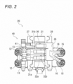
- FIG. 2 is a schematic top view of the variable valve device according to the first embodiment.
- FIGS. 3A and 3B show an example of switching operation of a cam of a variable valve device according to a comparative example.
- a cylinder head and a cylinder head cover are omitted.
- a cylinder head 10 is provided with four intake valves 12 for opening and closing intake ports 11 and four exhaust valves 15 for opening and closing exhaust ports 14 (only two of the intake ports and two of the exhaust ports are shown in FIG. 2 ).
- the intake valve 12 is pressed in a valve closing direction by a valve spring 13, and the exhaust valve 15 is pressed in a valve closing direction by a valve spring 16.
- a cylinder head cover 17 is attached to an upper surface of the cylinder head 10, and a valve operating chamber 18 is formed by the cylinder head 10 and the cylinder head cover 17.
- a variable valve device 20 that changes a valve lift amount in the cylinder head 10 is mounted in the valve operating chamber 18.
- the variable valve device 20 is provided with a camshaft 21 common to an intake side and an exhaust side, and an intake-side rocker shaft 27 and an exhaust-side rocker shaft 28 which are parallel to the camshaft 21.
- the camshaft 21 is rotatably supported in the cylinder head 10.
- the camshaft 21 is disposed between the intake valves 12 and the exhaust valves 15, and a low-speed cam 23, a high-speed cam 24, and an exhaust cam 25 are formed on an outer circumferential surface of the camshaft 21.
- Each of the cams 23 to 25 is formed in a plate shape in which a cam peak protrudes from a part of a base circle.
- a cam peak of the high-speed cam 24 is higher than that of the low-speed cam 23 in order to make a valve lift amount of the high-speed cam 24 larger than that of the low-speed cam 23.
- the intake-side rocker shaft 27 and exhaust-side rocker shaft 28 are attached to the cylinder head 10 above the camshaft 21.
- Rocker arms 31a, 31b of two types are swingably supported by the intake-side rocker shaft 27 (only one of the rocker arms 31a and one of the rocker arms 31b are shown in FIG. 2 ), and a pair of rocker arms 35 are swingably supported by the exhaust-side rocker shaft 28 (only one of the rocker arms 35 is shown in FIG. 2 ).
- the intake-side rocker arm 31a and the exhaust-side rocker arm 35 are formed in a seesaw shape having a point of effort and a point of load, and the intake-side rocker arm 31b is the point of effort of the rocker arm 31a.
- a roller 32a which is in rolling contact with the low-speed cam 23, is rotatably supported at one end of the intake-side rocker arm 31a, and a pair of intake valves 12 are coupled to the other end of the rocker arm 31a which branches into two parts.
- a roller 32b which is in rolling contact with the high-speed cam 24 is rotatably supported at one end of the intake-side rocker arm 31b, and the intake valves 12 are not coupled to the other end of the rocker arm 31b.
- a roller 36 which is in rolling contact with the exhaust cam 25, is rotatably supported at one end of the exhaust-side rocker arm 35, and a pair of exhaust valves 15 are coupled to the other end of the rocker arm 35 which branches into two parts.
- the rocker arms 31a, 31b can be coupled to each other.
- the rocker arms 31a, 31b When the engine rotates at a low speed or at a medium speed, the rocker arms 31a, 31b are not coupled to each other. Therefore, the rocker arm 31a is swung by the low-speed cam 23, and the rocker arm 31b is swung by the high-speed cam 24. Since a pair of intake valves 12 are coupled to the rocker arm 31a, the pair of intake valves 12 are moved as the low-speed cam 23 rotates. Since the cam peak of the low-speed cam 23 is low, the valve lift amount of the pair of intake valves 12 is small. Since the intake valve 12 is not coupled to the rocker arm 31b, the rocker arm 31b is idling as the high-speed cam 24 rotates.
- the rocker arms 31a, 31b When the engine rotates at a high speed, the rocker arms 31a, 31b are coupled to each other. Therefore, the rocker arms 31a, 31b are integrally swung by the high-speed cam 24. Since a pair of intake valves 12 are coupled to the rocker arm 31b via the rocker arm 31a, the pair of intake valves 12 are moved as the high-speed cam 24 rotates. Since the cam peak of the high-speed cam 24 is high, the valve lift amount of the pair of intake valves 12 is large. In this way, by switching a coupling state of the rocker arms 31a, 31b, the low-speed cam 23 and the high-speed cam 24 that move the intake valves 12 are switched.
- the variable valve device 20 is provided with a switching mechanism 40 that switches between a coupling state and a non-coupling state of the rocker arms 31a, 31b by an oil pressure.
- An accommodation hole is formed in each of the rocker arms 31a, 31b, and a coupling pin 41 is installed in the accommodation hole of the rocker arm 31b.
- a coupling pin 102 is moved regardless of a phase of a camshaft 101. Therefore, in a case where a low-speed cam 103 is switched to a high-speed cam 104, when the coupling pin 102 protrudes from an accommodation hole of a rocker arm 106b immediately before a valve lift of intake valves 105, the coupling pin 102 may not sufficiently enter an accommodation hole of a rocker arm 106a. As shown in FIG.
- variable valve device 20 of the present embodiment performs the switching operation between the low-speed cam 23 and the high-speed cam 24 in consideration of a phase of the camshaft 21.
- the coupling pin 41 is pushed from the accommodation hole of the rocker arm 31b to the accommodation hole of the rocker arm 31a while avoiding a valve lift in which the accommodation holes of the rocker arms 31a, 31b do not match.
- the rocker arms 31a, 31b are smoothly coupled by the coupling pin 41, the coupling state of the rocker arms 31a, 31b is not released during a valve lift performed by the high-speed cam 24, and thus generation of abnormal noise is suppressed.
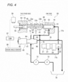
- FIG. 4 is a schematic diagram of the variable valve device according to the first embodiment.
- FIG. 5 is a schematic diagram of an operation passage and a shortcut passage according to the first embodiment.
- FIGS. 6A to 6C are views illustrating movement operation of a hydraulic piston according to the first embodiment.
- an oil supply path 71 extends from the oil pan 70 toward an oil control valve 60.
- Oil is pumped up from the oil pan 70 by an oil pump 72 in the middle of the oil supply path 71, and the oil is supplied to the oil control valve 60 through an oil filter 73.
- the oil control valve 60 is formed by a valve housing 61 in which a valve spool (not shown) is accommodated, and a solenoid 62 that moves the valve spool forward and backward. When the valve spool is moved forward and backward by the solenoid 62, an oil passage in the oil control valve 60 is switched.
- An input port 63, a low-speed port 64, a high-speed port 65, and a drain port 66 are formed in the valve housing 61.
- the oil supply path 71 is connected with the input port 63, a dead-end passage 74 is connected with the low-speed port 64, an operation passage (oil passage) 75 is connected with the high-speed port 65, and a drain passage 76 is connected with the drain port 66.
- An output destination of the dead-end passage 74 is closed, and the operation passage 75 extends from the oil control valve 60 toward the switching mechanism 40.
- the drain passage 76 extends from the oil control valve 60 to a position above the oil pan 70, and the oil drops from an outlet of the drain passage 76 into the oil pan 70.
- the input port 63 is connected to any one of the low-speed port 64 and the high-speed port 65
- the drain port 66 is connected to the other of the low-speed port 64 and the high-speed port 65.
- the oil is output from the oil control valve 60 to any one of the dead-end passage 74 and the operation passage 75, and excess oil is discharged from the other of the dead-end passage 74 and the operation passage 75 to the oil control valve 60 (drain passage 76). In this way, an oil pressure for the switching mechanism 40 is controlled by the oil control valve 60.
- a part of the operation passage 75 extending from the oil control valve 60 to the switching mechanism 40 is formed by an oil groove 26 of the camshaft 21.
- the low-speed cam 23, the high-speed cam 24, and the exhaust cam 25 (not shown in FIG. 4 ) are formed on the camshaft 21, and the oil groove 26 is formed in a part of the outer circumferential surface of the camshaft 21 supported by a cam housing (not shown).
- a shortcut passage (another oil passage) 78 is branched from the upstream passage 77a of the operation passage 75.
- the shortcut passage 78 extends directly from the oil control valve 60 to the switching mechanism 40 without passing through the oil groove 26 of the camshaft 21. Therefore, the oil is continuously supplied from the oil control valve 60 to the switching mechanism 40 through the shortcut passage 78.
- the oil supply through the operation passage 75 is used as a trigger for moving a hydraulic piston 52 of the switching mechanism 40, and the oil supply through the shortcut passage 78 is used to hold the hydraulic piston 52 in a push-out state.
- the rocker arms 31a, 31b are adjacent to each other, but upper portions of the rocker arms 31a, 31b face each other with a slight gap C therebetween.
- Accommodation holes 33a, 33b parallel to the camshaft 21 are formed in the upper portions of the rocker arms 31a, 31b.
- the accommodation hole 33a of the rocker arm 31a and the accommodation hole 33b of the rocker arm 31b have the same hole diameter, and are coaxially formed such that the accommodation holes 33a, 33b are in communication with each other in a non-lift-up state.
- the coupling pin 41 is provided in the accommodation hole 33b of the rocker arm 31b, and a return pin 44 is provided in the accommodation hole 33a of the rocker arm 31a.
- the accommodation holes 33a, 33b of the rocker arms 31a, 31b are formed straight, and flange pins are used as the coupling pin 41 and the return pin 44.
- a flange 42 is formed at one end of the coupling pin 41 protruding from the rocker arm 31b to one side, and a flange 45 is formed at the other end of the return pin 44 protruding from the rocker arm 31a to the other side.
- the flange 42 of the coupling pin 41 abuts against the rocker arm 31b to restrict pushing of the coupling pin 41
- the flange 45 of the return pin 44 abuts against the rocker arm 31a to restrict pushing back of the return pin 44.
- a sliding chamber 51 is formed on one side of the rocker arm 31b, and the hydraulic piston 52 is installed in the sliding chamber 51.
- a pressing surface of the hydraulic piston 52 is in contact with the coupling pin 41, and the coupling pin 41 is moved to the other side by the hydraulic piston 52.
- a sliding chamber 53 is formed on the other side of the rocker arm 31a.
- a spring pin 54 is installed in the sliding chamber 53.
- a pressing surface of the spring pin 54 is in contact with the return pin 44, and the return pin 44 is returned to the one side by the spring pin 54.
- a sensing arm 55 extends from the spring pin 54 to the other side.
- the coupling state of the rocker arms 31a, 31b is switched by the coupling pin 41 being moved by the oil pressure.
- the pair of intake valves 12 are operated by the low-speed cam 23 via the rocker arm 31a.
- the pair of intake valves 12 are operated by the high-speed cam 24 via the rocker arms 31a, 31b.
- the cam that moves the pair of intake valves 12 is switched by switching the coupling state of the rocker arms 31a, 31b by the coupling pin 41.
- the variable valve device 20 includes an engine control module (ECM) 57, an engine angle sensor 58, and a switching sensor 59.
- ECM engine control module
- An engine rotation speed is detected by the engine angle sensor 58, and a coupling command signal is output from the ECM 57 to the solenoid 62 when the engine rotation speed is equal to or higher than a predetermined rotation speed, and a release command signal is output from the ECM 57 to the solenoid 62 when the engine rotation speed is lower than the predetermined rotation speed.
- the switching sensor 59 detects the switching between the coupling state and the non-coupling state of the rocker arms 31a, 31b based on movement of a tip end of the sensing arm 55.
- a failure of the variable valve device 20 such as a switching operation failure is determined by comparing a command signal of the ECM 57 with a detection signal of the switching sensor 59.
- the upstream passage 77a of the operation passage 75 extends from the oil control valve 60 toward the camshaft 21, and the downstream passage 77b of the operation passage 75 extends from the camshaft 21 toward the hydraulic piston 52 of the switching mechanism 40.
- a downstream end of the upstream passage 77a and an upstream end of the downstream passage 77b are positioned on the same circumference on the outer circumferential surface of the camshaft 21.
- the oil groove 26 is formed in a circumferential direction on the circumference of the outer circumferential surface of the camshaft 21.
- the oil groove 26 functions as the operation passage 75 for supplying the oil to the hydraulic piston 52 in both the upstream passage 77a and the downstream passage 77b.
- the oil is supplied from the oil control valve 60 to the hydraulic piston 52 only while the upstream passage 77a and the downstream passage 77b are connected via the oil groove 26.
- the oil groove 26 is formed such that the upstream passage 77a and the downstream passage 77b are connected at an end timing of a valve lift, and the upstream passage 77a and the downstream passage 77b are separated from each other before a valve lift starts. That is, the oil groove 26 is formed such that the oil starts to be supplied from the oil control valve 60 to the hydraulic piston 52 at an end timing of a valve lift, and the supply of the oil to the hydraulic piston 52 ends before a valve lift starts.
- the shortcut passage 78 extends directly from the oil control valve 60 to the hydraulic piston 52.
- the shortcut passage 78 is shorter than the operation passage 75.
- a stepwise oil supply structure for the hydraulic piston 52 is formed such that the oil is supplied to the hydraulic piston 52 from the shortcut passage 78 after the oil is supplied to the hydraulic piston 52 from the operation passage 75.
- the hydraulic piston 52 may move only by the intermittent supply of the oil from the operation passage 75, the hydraulic piston 52 is stably held by the direct supply of the oil from the shortcut passage 78.
- the hydraulic piston 52 is installed in the cylindrical sliding chamber 51 of the cylinder head 10.
- a downstream end of the operation passage 75 (the downstream passage 77b) is opened in an inner bottom surface of the sliding chamber 51, and a downstream end of the shortcut passage 78 is opened in an inner circumferential surface of the sliding chamber 51.
- a supply direction of the oil from the operation passage 75 to the hydraulic piston 52 is directed to an advancing direction of the hydraulic piston 52, and a supply direction of the oil from the shortcut passage 78 to the hydraulic piston 52 is directed to a radial direction of the hydraulic piston 52.
- the downstream end of the shortcut passage 78 is closed by an outer circumferential surface of the hydraulic piston 52.
- FIGS. 7A and 7B are views illustrating the coupling operation of the variable valve device according to the first embodiment.
- FIGS. 7A and 7B for convenience of description, the reference numerals in FIG. 4 are used as appropriate.
- the oil is not supplied from the oil control valve 60 to the hydraulic piston 52.
- a pressing force is not applied from the hydraulic piston 52 to the coupling pin 41, and a spring force of the spring pin 54 is applied to the return pin 44.
- the flange 45 of the return pin 44 abuts against the rocker arm 31a, and the return pin 44 is positioned at an initial position.
- the other end 43 of the coupling pin 41 is in contact with one end 46 of the return pin 44 at a non-coupling position P1 in the gap C between the rocker arms 31a, 31b.
- the other end 43 of the coupling pin 41 is located outside the rocker arm 31b, and the rocker arms 31a, 31b are separated from each other.
- the oil starts to be supplied from the oil control valve 60 to the hydraulic piston 52.
- the upstream passage 77a and the downstream passage 77b of the operation passage 75 are intermittently connected through the oil groove 26, and the oil is intermittently supplied from the operation passage 75 to the hydraulic piston 52.
- the oil starts to be supplied at an end timing of a valve lift of the intake valves 12 in order not to hinder the coupling operation of the rocker arms 3 1a, 3 1b. Therefore, the hydraulic piston 52 is smoothly pushed out in the advancing direction by the oil from the operation passage 75.
- the coupling pin 41 is pushed in by the hydraulic piston 52, and the spring pin 54 is moved to the other side by the coupling pin 41 via the return pin 44.
- the other end 43 of the coupling pin 41 is moved to the other side from the non-coupling position P1 to a coupling position P2 of the rocker arm 31a.
- the rocker arms 31a, 31b are coupled to each other via the coupling pin 41.
- the downstream end of the shortcut passage 78 is opened by the movement of the hydraulic piston 52, and the position of the hydraulic piston 52 is maintained by the continuous oil supply from the shortcut passage 78.
- variable valve device 20 of the first embodiment since the oil starts to be supplied from the oil control valve 60 to the switching mechanism 40 at an end timing of a valve lift, the coupling operation of the rocker arms 31a, 31b is not hindered by the valve lift, and the rocker arms 31a, 31b are appropriately coupled by the coupling pin 41. Therefore, the coupling state of the rocker arms 31a, 31b is not released in the middle of the valve lift, the generation of abnormal noise is suppressed, and the durability of the variable valve device 20 is improved.
- variable valve device according to a second embodiment will be described with reference to FIGS. 8 to 10B .
- the variable valve device of the second embodiment is different from the variable valve device of the first embodiment in that a cam for moving an intake valve is switched by a shift cam. Therefore, in the second embodiment, description of the same configuration as that of the first embodiment will be omitted.
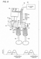
- FIG. 8 is a perspective view of the variable valve device according to the second embodiment.
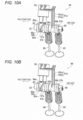
- FIGS. 9A to 10B are views illustrating switching operation of the variable valve device according to the second embodiment.
- a shift cam 83 is slidably and integrally rotatably provided on a shaft main body 82 of a camshaft 81 of the second embodiment.
- a guide groove (not shown) is formed in an axial direction of the shift cam 83 on an inner circumferential surface of the shift cam 83, and a guide rail 85 that enters the guide groove is formed in the axial direction on an outer circumferential surface of the shaft main body 82.
- low-speed cams 86a, 86b and high-speed cams 87a, 87b are formed, and switching grooves 88a, 88b for sliding the shift cam 83 with respect to the shaft main body 82 are formed.
- a single oil groove 89 for connection of each of the oil passages 91a, 91b is formed in the outer circumferential surface of the shift cam 83.
- a pair of intake valves 90 are provided corresponding to the low-speed cams 86a, 86b and the high-speed cams 87a, 87b, and a hydraulic switching switch (switching mechanism) 95 is provided corresponding to the switching grooves 88a, 88b.
- the switching switch 95 is provided with switching pins 96a, 96b that enter the switching grooves 88a, 88b by oil pressure, and when the switching pins 96a, 96b selectively enter the switching grooves 88a, 88b, the shift cam 83 is slid and the cam is switched.
- the switching pin 96a is inserted into the switching groove 88a to switch to the high-speed cams 87a, 87b, and the switching pin 96b is inserted into the switching groove 88b to switch to the low-speed cams 86a, 86b.
- a part of the oil passages 91a, 91b extending from an oil control valve 80 to the switching pins 96a, 96b is formed by the oil groove 89.
- An upstream passage 92aa of the oil passage 91a extends from the oil control valve 80 toward the shift cam 83, and a downstream passage 92ab of the oil passage 91a extends from the shift cam 83 toward the switching pin 96a.
- a downstream end of the upstream passage 92aa and an upstream end of the downstream passage 92ab are positioned on the same circumference 97a on the outer circumferential surface of the shift cam 83.
- the oil groove 89 is positioned on the circumference 97a.
- An upstream passage 92ba of the oil passage 91b extends from the oil control valve 80 toward the shift cam 83, and a downstream passage 92bb of the oil passage 91b extends from the shift cam 83 toward the switching pin 96b.
- a downstream end of the upstream passage 92ba and an upstream end of the downstream passage 92bb are positioned on the same circumference 97b on the outer circumferential surface of the shift cam 83.
- the oil groove 89 is positioned on the circumference 97b.
- the upstream passage 92aa and the downstream passage 92ab are intermittently connected through the oil groove 89.
- the oil groove 89 is formed such that the upstream passage 92aa and the downstream passage 92ab are connected at an end timing of a valve lift, and the upstream passage 92aa and the downstream passage 92ab are separated from each other before a valve lift starts. That is, the oil groove 89 is formed such that the oil starts to be supplied from the oil control valve 80 to the switching pin 96a at an end timing of a valve lift, and the supply of the oil to the switching pin 96a ends before a valve lift starts.
- the switching operation of the shift cam 83 is not hindered by the valve lift.
- the switching operation of the shift cam 83 ends before a valve lift starts, the shift cam 83 is not switched in the middle of the valve lift.
- the upstream passage 92ba and the downstream passage 92bb are intermittently connected through the oil groove 89.
- the switching operation of the shift cam 83 is also performed while avoiding the valve lift.
- the supply of oil from the oil control valve 80 to the switching switch 95 is stopped, and the switching pin 96a is pulled out of the switching groove 88a by a repulsive force of the internal spring, and the sliding of the shift cam 83 is ended. Since the switching pins 96a, 96b are pulled out of the switching grooves 88a, 88b, no force is applied to the shift cam 83 in a sliding direction. At this time, the high-speed cams 87a, 87b of the shift cam 83 are positioned on the pair of intake valves 90, and the pair of intake valves 90 are lifted by the high-speed cams 87a, 87b. Further, the oil groove 89 is positioned on the circumference 97b.
- the oil starts to be supplied from the oil control valve 80 to the switching switch 95.
- the upstream passage 92ba and the downstream passage 92bb of the oil passage 91b are intermittently connected through the oil groove 89, and the oil is intermittently supplied from the oil passage 91b to the switching pin 96b.
- the switching pin 96b enters the switching groove 88b, and the shift cam 83 is slid to the one side. Since the oil starts to be supplied at an end timing of a valve lift of the intake valves 90, the sliding of the shift cam 83 is not hindered by the valve lift.
- variable valve device 99 of the second embodiment since the oil starts to be supplied from the oil control valve 80 to the switching switch 95 at an end timing of a valve lift, the cam is not switched in the middle of the valve lift. Therefore, generation of abnormal noise is suppressed, and the durability of the variable valve device 99 is improved.
- the end timing of the valve lift is not limited to a timing at which the valve lift is completely ended, and includes a timing immediately before the end at which the valve lift can be regarded as being ended.
- the oil starts to be supplied from the oil control valve to the switching mechanism (hydraulic piston, switching switch) at the end timing of the valve lift, but the oil supply timing is not limited to the end timing of the valve lift.
- the oil may start to be supplied from the oil control valve to the switching mechanism in a zero range in which no valve lift occurs. With such a configuration, the switching operation of the cam can also be suppressed from being hindered by the valve lift.
- the oil groove is formed such that the supply of the oil to the switching mechanism (the hydraulic piston, the switching switch) through the oil passage ends before the valve lift starts, but the oil groove may be formed longer.
- the oil groove may be formed such that the supply of the oil to the switching mechanism through the oil passage ends after the valve lift ends and before a next valve lift starts.
- the flange pins are used as the coupling pin and the return pin, but straight pins may be used as the coupling pin and the return pin.
- a seesaw type rocker arm is described as an example, but the type of rocker arm is not particularly limited, and a finger follower type rocker arm may be used.
- a pair of rocker arms are provided on the intake side of the variable valve device, but a plurality of rocker arms may be provided on the intake side of the variable valve device. For example, three or more rocker arms may be provided on the intake side of the variable valve device.
- the plurality of rocker arms are adjacent to each other, but the plurality of rocker arms may be separated from each other.
- the operation passage and the shortcut passage are formed in the cylinder head, but it is sufficient that at least the operation passage is formed in the cylinder head.
- variable valve device of the present embodiment is not limited to being used in an engine of a saddle-type vehicle described above, and may be used in an engine of another type of vehicle.
- the saddle-type vehicle is not limited to a motorcycle, and may be any vehicle on which an engine is mounted.
- the saddle-type vehicle is not limited to general vehicles in which a driver rides in a posture of straddling a seat, and includes a scooter type vehicle in which a driver rides without straddling a seat.
- a variable valve device (20) provided in a cylinder head (10) and capable of changing a valve lift amount includes:a camshaft (21, 81) on which a plurality of cams (low-speed cams 23, 86a, 86b, high-speed cams 24, 87a, 87b) with different valve lift amounts are formed; a switching mechanism (40, switching switch 95) configured to switch a cam for moving a valve (intake valves 12, 90) among the plurality of cams; and an oil control valve (60, 80) configured to control an oil pressure for the switching mechanism, and oil starts to be supplied from the oil control valve to the switching mechanism at an end timing of a valve lift or in a zero range in which no valve lift occurs.
- the switching operation of the cam is not hindered by the valve lift. Therefore, occurrence of abnormal noise caused by a malfunction in the switching operation of the cam is suppressed, and the durability of the variable valve device is improved.
- the variable valve device further includes: a plurality of rocker arms (31a, 31b) configured to abut with the plurality of cams to move the valve, the switching mechanism includes a coupling pin (41) configured to couple the plurality of rocker arms and a hydraulic piston (52) configured to move the coupling pin, the cam is switched by switching a coupling state of the plurality of rocker arms by the coupling pin, a part of an oil passage (operation passage 75) extending from the oil control valve to the switching mechanism is formed by an oil groove (26) of the camshaft, and the oil groove is formed such that the oil starts to be supplied from the oil control valve to the switching mechanism at the end timing of the valve lift or in the zero range in which no valve lift occurs.
- the switching mechanism includes a coupling pin (41) configured to couple the plurality of rocker arms and a hydraulic piston (52) configured to move the coupling pin
- the cam is switched by switching a coupling state of the plurality of rocker arms by the coupling pin
- the oil groove is formed in the camshaft, the oil is intermittently supplied from the oil control valve to the switching mechanism through the oil passage as the camshaft rotates. Since the oil starts to be supplied from the oil control valve to the switching mechanism at the end timing of the valve lift or in the zero range, the coupling operation of the plurality of rocker arms is not hindered by the valve lift, and the plurality of rocker arms are appropriately coupled by the coupling pin. Therefore, the coupling state of the plurality of rocker arms is not released in the middle of the valve lift, and the generation of abnormal noise is suppressed.
- another oil passage extends directly from the oil control valve to the switching mechanism, and after the oil is supplied to the hydraulic piston from the oil passage, the oil is supplied to the hydraulic piston from the other oil passage.
- the hydraulic piston may move only by intermittent supply of the oil from the oil passage, but the hydraulic piston can be held by direct supply of the oil from the other oil passage.
- the other oil passage is shorter than the oil passage. According to the configuration, the oil is smoothly supplied to the hydraulic piston from the other oil passage, and the hydraulic piston can be stably held.
- a supply direction of the oil to the hydraulic piston from the oil passage is directed toward an advancing direction of the hydraulic piston
- a supply direction of the oil to the hydraulic piston from the other oil passage is directed toward a radial direction of the hydraulic piston
- the hydraulic piston when the hydraulic piston is at a retracted position, a downstream end of the other oil passage is closed by an outer circumferential surface of the hydraulic piston, and the downstream end of the other oil passage is opened by moving the hydraulic piston in the advancing direction.
- the camshaft includes a shift cam (83) on which the plurality of cams are formed, and a shaft main body (82) on which the shift cam is slidably and integrally rotatably provided, a plurality of switching grooves (88a, 88b) for sliding the shift cam with respect to the shaft main body are formed on the shift cam, and the switching mechanism is provided with a plurality of switching pins (96a, 96b) configured to enter the plurality of switching grooves by the oil pressure, the shift cam is slid to switch the cam by causing the plurality of switching pins to selectively enter the plurality of switching grooves, a part of an oil passage (91a, 91b) extending from the oil control valve to the switching mechanism is formed by an oil groove (89) of the shift cam, and the oil groove is formed such that the oil starts to be supplied from the oil control valve to the switching mechanism at the end timing of the valve lift or in the zero range in which no valve lift occurs.
- the oil groove is formed in the shift cam, the oil is intermittently supplied from the oil control valve to the switching mechanism through the oil passage as the shift cam rotates. Since the oil starts to be supplied from the oil control valve to the switching mechanism at the end timing of the valve lift or in the zero range, the cam is not switched in the middle of a valve lift, and thus generation of abnormal noise is suppressed.
- the oil groove is formed such that a supply of the oil to the switching mechanism through the oil passage ends before the valve lift starts. According to the configuration, since the switching operation of the cam ends before the valve lift starts, the cam is not switched in the middle of the valve lift.
- the oil groove is formed such that a supply of the oil to the switching mechanism through the oil passage ends after the valve lift ends and before a next valve lift starts. According to the configuration, a long supply time of the oil to the switching mechanism through the oil passage can be secured, and the switching operation of the cam performed by the switching mechanism can be stabilized.
- the technique of the present invention is not limited to the above-described embodiments, and various changes, replacements, and modifications may be made without departing from the gist of the technical concept. Further, as long as the technical concept can be realized in another way by the progress of the technique or another derivative technique, the present invention may be implemented using the method. Therefore, the claims cover all embodiments that may fall within the scope of the technical concept.
Landscapes
- Engineering & Computer Science (AREA)
- Mechanical Engineering (AREA)
- General Engineering & Computer Science (AREA)
- Valve Device For Special Equipments (AREA)
- Valve-Gear Or Valve Arrangements (AREA)
Abstract
Description
- The present invention relates to a variable valve device.
- In the related art, there is a variable valve device in which a valve lift amount is changed according to an engine rotation speed (see, for example, Patent Literature 1). In the variable valve device disclosed in
Patent Literature 1, a valve is moved via a rocker arm as a camshaft rotates. A pair of cams with different lift amounts are formed on the camshaft, and a pair of the rocker arms are provided corresponding to the pair of cams. By switching a coupling state of the pair of rocker arms by a switching mechanism of the variable valve device, a cam that lifts the valve is switched to change the valve lift amount. - Patent Literature 1:
JP2009-264199A - In such a variable valve device, switching operation of the cam is performed by the switching mechanism regardless of a phase of the camshaft. In a case where the switching operation of the cam is performed during a valve lift, abnormal noise may be generated due to malfunction of the switching operation, which may reduce the durability of the variable valve device. A similar malfunction occurs not only in the switching operation of the cam using the rocker arm, but also in the switching operation of the cam using a shift cam.
- The present invention is made in view of the above circumstances, and an object of the present invention is to provided a variable valve device which can be improved in durability while reducing abnormal noise when a valve lift amount is changed.
- There is provided a variable valve device provided in a cylinder head and capable of changing a valve lift amount, including: a camshaft on which a plurality of cams with different valve lift amounts are formed; a switching mechanism configured to switch a cam for moving a valve among the plurality of cams; and an oil control valve configured to control an oil pressure for the switching mechanism. Oil starts to be supplied from the oil control valve to the switching mechanism at an end timing of a valve lift or in a zero range in which no valve lift occurs.
- According to the variable valve device of an aspect of the present invention, since the oil starts to be supplied from the oil control valve to the switching mechanism at the end timing of the valve lift or in the zero range, the switching operation of the cam is not hindered by the valve lift. Therefore, occurrence of abnormal noise caused by a malfunction in the switching operation of the cam is suppressed, and the durability of the variable valve device is improved.
-
-
FIG. 1 is a schematic cross-sectional view of a variable valve device according to a first embodiment. -
FIG. 2 is a schematic top view of the variable valve device according to the first embodiment. -
FIGS. 3A and 3B show an example of switching operation of a cam of a variable valve device according to a comparative example. -
FIG. 4 is a schematic diagram of the variable valve device according to the first embodiment. -
FIG. 5 is a schematic diagram of an operation passage and a shortcut passage according to the first embodiment. -
FIGS. 6A to 6C are views illustrating movement operation of a hydraulic piston according to the first embodiment. -
FIGS. 7A and 7B are views illustrating coupling operation of the variable valve device according to the first embodiment. -
FIG. 8 is a perspective view of a variable valve device according to a second embodiment. -
FIGS. 9A and 9B are views illustrating switching operation of the variable valve device according to the second embodiment. -
FIGS. 10A and 10B are views illustrating the switching operation of the variable valve device according to the second embodiment. - A variable valve device according to an aspect of the present invention is provided in a cylinder head, and changes a valve lift amount. A plurality of cams with different valve lift amounts are formed on a camshaft, and a cam for moving the valve is switched among the plurality of cams by a switching mechanism. An oil pressure for the switching mechanism is controlled by an oil control valve, and oil starts to be supplied from the oil control valve to the switching mechanism at an end timing of a valve lift or in a zero range in which no valve lift occurs. Therefore, the switching operation of the cam is not hindered by the valve lift. Therefore, occurrence of abnormal noise caused by a malfunction in the switching operation of the cam is suppressed, and the durability of the variable valve device is improved.
- Hereinafter, a variable valve device according to a first embodiment will be described with reference to the attached drawings.
FIG. 1 is a schematic cross-sectional view of the variable valve device according to the first embodiment.FIG. 2 is a schematic top view of the variable valve device according to the first embodiment.FIGS. 3A and 3B show an example of switching operation of a cam of a variable valve device according to a comparative example. InFIG. 2 , a cylinder head and a cylinder head cover are omitted. - As shown in
FIGS. 1 and2 , acylinder head 10 is provided with fourintake valves 12 for opening andclosing intake ports 11 and fourexhaust valves 15 for opening and closing exhaust ports 14 (only two of the intake ports and two of the exhaust ports are shown inFIG. 2 ). Theintake valve 12 is pressed in a valve closing direction by avalve spring 13, and theexhaust valve 15 is pressed in a valve closing direction by avalve spring 16. Acylinder head cover 17 is attached to an upper surface of thecylinder head 10, and avalve operating chamber 18 is formed by thecylinder head 10 and thecylinder head cover 17. Avariable valve device 20 that changes a valve lift amount in thecylinder head 10 is mounted in thevalve operating chamber 18. - The
variable valve device 20 is provided with acamshaft 21 common to an intake side and an exhaust side, and an intake-side rocker shaft 27 and an exhaust-side rocker shaft 28 which are parallel to thecamshaft 21. Thecamshaft 21 is rotatably supported in thecylinder head 10. Thecamshaft 21 is disposed between theintake valves 12 and theexhaust valves 15, and a low-speed cam 23, a high-speed cam 24, and anexhaust cam 25 are formed on an outer circumferential surface of thecamshaft 21. Each of thecams 23 to 25 is formed in a plate shape in which a cam peak protrudes from a part of a base circle. A cam peak of the high-speed cam 24 is higher than that of the low-speed cam 23 in order to make a valve lift amount of the high-speed cam 24 larger than that of the low-speed cam 23. - The intake-
side rocker shaft 27 and exhaust-side rocker shaft 28 are attached to thecylinder head 10 above thecamshaft 21.Rocker arms rocker arms 31a and one of therocker arms 31b are shown inFIG. 2 ), and a pair ofrocker arms 35 are swingably supported by the exhaust-side rocker shaft 28 (only one of therocker arms 35 is shown inFIG. 2 ). The intake-side rocker arm 31a and the exhaust-side rocker arm 35 are formed in a seesaw shape having a point of effort and a point of load, and the intake-side rocker arm 31b is the point of effort of therocker arm 31a. - A
roller 32a, which is in rolling contact with the low-speed cam 23, is rotatably supported at one end of the intake-side rocker arm 31a, and a pair ofintake valves 12 are coupled to the other end of therocker arm 31a which branches into two parts. Aroller 32b, which is in rolling contact with the high-speed cam 24 is rotatably supported at one end of the intake-side rocker arm 31b, and theintake valves 12 are not coupled to the other end of therocker arm 31b. Aroller 36, which is in rolling contact with theexhaust cam 25, is rotatably supported at one end of the exhaust-side rocker arm 35, and a pair ofexhaust valves 15 are coupled to the other end of therocker arm 35 which branches into two parts. Therocker arms - When the engine rotates at a low speed or at a medium speed, the
rocker arms rocker arm 31a is swung by the low-speed cam 23, and therocker arm 31b is swung by the high-speed cam 24. Since a pair ofintake valves 12 are coupled to therocker arm 31a, the pair ofintake valves 12 are moved as the low-speed cam 23 rotates. Since the cam peak of the low-speed cam 23 is low, the valve lift amount of the pair ofintake valves 12 is small. Since theintake valve 12 is not coupled to therocker arm 31b, therocker arm 31b is idling as the high-speed cam 24 rotates. - When the engine rotates at a high speed, the
rocker arms rocker arms speed cam 24. Since a pair ofintake valves 12 are coupled to therocker arm 31b via therocker arm 31a, the pair ofintake valves 12 are moved as the high-speed cam 24 rotates. Since the cam peak of the high-speed cam 24 is high, the valve lift amount of the pair ofintake valves 12 is large. In this way, by switching a coupling state of therocker arms speed cam 23 and the high-speed cam 24 that move theintake valves 12 are switched. - The
variable valve device 20 is provided with aswitching mechanism 40 that switches between a coupling state and a non-coupling state of therocker arms rocker arms coupling pin 41 is installed in the accommodation hole of therocker arm 31b. When a part of thecoupling pin 41 enters the accommodation hole of therocker arm 31a from the accommodation hole of therocker arm 31b, therocker arms coupling pin 41. When a part of thecoupling pin 41 is pushed back from the accommodation hole of therocker arm 31a to the accommodation hole of therocker arm 31b, the coupling between therocker arms - As shown in
FIG. 3A , in avariable valve device 100 of a comparative example, acoupling pin 102 is moved regardless of a phase of acamshaft 101. Therefore, in a case where a low-speed cam 103 is switched to a high-speed cam 104, when thecoupling pin 102 protrudes from an accommodation hole of arocker arm 106b immediately before a valve lift ofintake valves 105, thecoupling pin 102 may not sufficiently enter an accommodation hole of arocker arm 106a. As shown inFIG. 3B , when thecoupling pin 102 is disengaged from the accommodation hole of therocker arm 106a in the middle of a valve lift performed by the high-speed cam 104 and a coupling state is released, a malfunction occurs in which therocker arm 106a collides with the low-speed cam 103 to generate abnormal noise, and the durability of thevariable valve device 100 is reduced. - Therefore, the
variable valve device 20 of the present embodiment performs the switching operation between the low-speed cam 23 and the high-speed cam 24 in consideration of a phase of thecamshaft 21. At the time of switching from the low-speed cam 23 to the high-speed cam 24, thecoupling pin 41 is pushed from the accommodation hole of therocker arm 31b to the accommodation hole of therocker arm 31a while avoiding a valve lift in which the accommodation holes of therocker arms rocker arms coupling pin 41, the coupling state of therocker arms speed cam 24, and thus generation of abnormal noise is suppressed. - Hereinafter, the variable valve device according to the first embodiment will be described with reference to
FIGS. 4 to 6C .FIG. 4 is a schematic diagram of the variable valve device according to the first embodiment.FIG. 5 is a schematic diagram of an operation passage and a shortcut passage according to the first embodiment.FIGS. 6A to 6C are views illustrating movement operation of a hydraulic piston according to the first embodiment. - As shown in
FIG. 4 , in thevariable valve device 20, anoil supply path 71 extends from theoil pan 70 toward anoil control valve 60. Oil is pumped up from theoil pan 70 by anoil pump 72 in the middle of theoil supply path 71, and the oil is supplied to theoil control valve 60 through anoil filter 73. Theoil control valve 60 is formed by avalve housing 61 in which a valve spool (not shown) is accommodated, and asolenoid 62 that moves the valve spool forward and backward. When the valve spool is moved forward and backward by thesolenoid 62, an oil passage in theoil control valve 60 is switched. - An
input port 63, a low-speed port 64, a high-speed port 65, and adrain port 66 are formed in thevalve housing 61. Theoil supply path 71 is connected with theinput port 63, a dead-end passage 74 is connected with the low-speed port 64, an operation passage (oil passage) 75 is connected with the high-speed port 65, and adrain passage 76 is connected with thedrain port 66. An output destination of the dead-end passage 74 is closed, and theoperation passage 75 extends from theoil control valve 60 toward theswitching mechanism 40. Thedrain passage 76 extends from theoil control valve 60 to a position above theoil pan 70, and the oil drops from an outlet of thedrain passage 76 into theoil pan 70. - By moving the valve spool of the
oil control valve 60, theinput port 63 is connected to any one of the low-speed port 64 and the high-speed port 65, and thedrain port 66 is connected to the other of the low-speed port 64 and the high-speed port 65. The oil is output from theoil control valve 60 to any one of the dead-end passage 74 and theoperation passage 75, and excess oil is discharged from the other of the dead-end passage 74 and theoperation passage 75 to the oil control valve 60 (drain passage 76). In this way, an oil pressure for theswitching mechanism 40 is controlled by theoil control valve 60. - A part of the
operation passage 75 extending from theoil control valve 60 to theswitching mechanism 40 is formed by anoil groove 26 of thecamshaft 21. As described above, the low-speed cam 23, the high-speed cam 24, and the exhaust cam 25 (not shown inFIG. 4 ) are formed on thecamshaft 21, and theoil groove 26 is formed in a part of the outer circumferential surface of thecamshaft 21 supported by a cam housing (not shown). By rotating thecamshaft 21, connection and separation between anupstream passage 77a and adownstream passage 77b of theoperation passage 75 are alternately repeated. Therefore, the oil is intermittently supplied from theoil control valve 60 to theswitching mechanism 40 through theoperation passage 75. - Further, a shortcut passage (another oil passage) 78 is branched from the
upstream passage 77a of theoperation passage 75. Theshortcut passage 78 extends directly from theoil control valve 60 to theswitching mechanism 40 without passing through theoil groove 26 of thecamshaft 21. Therefore, the oil is continuously supplied from theoil control valve 60 to theswitching mechanism 40 through theshortcut passage 78. As will be described in detail later, the oil supply through theoperation passage 75 is used as a trigger for moving ahydraulic piston 52 of theswitching mechanism 40, and the oil supply through theshortcut passage 78 is used to hold thehydraulic piston 52 in a push-out state. - As described above, the
rocker arms rocker arms Accommodation holes camshaft 21 are formed in the upper portions of therocker arms accommodation hole 33a of therocker arm 31a and theaccommodation hole 33b of therocker arm 31b have the same hole diameter, and are coaxially formed such that theaccommodation holes coupling pin 41 is provided in theaccommodation hole 33b of therocker arm 31b, and areturn pin 44 is provided in theaccommodation hole 33a of therocker arm 31a. - The
accommodation holes rocker arms coupling pin 41 and thereturn pin 44. Aflange 42 is formed at one end of thecoupling pin 41 protruding from therocker arm 31b to one side, and aflange 45 is formed at the other end of thereturn pin 44 protruding from therocker arm 31a to the other side. In this case, theflange 42 of thecoupling pin 41 abuts against therocker arm 31b to restrict pushing of thecoupling pin 41, and theflange 45 of thereturn pin 44 abuts against therocker arm 31a to restrict pushing back of thereturn pin 44. - In the
cylinder head 10, a slidingchamber 51 is formed on one side of therocker arm 31b, and thehydraulic piston 52 is installed in the slidingchamber 51. A pressing surface of thehydraulic piston 52 is in contact with thecoupling pin 41, and thecoupling pin 41 is moved to the other side by thehydraulic piston 52. Further, in thecylinder head 10, a slidingchamber 53 is formed on the other side of therocker arm 31a. Aspring pin 54 is installed in the slidingchamber 53. A pressing surface of thespring pin 54 is in contact with thereturn pin 44, and thereturn pin 44 is returned to the one side by thespring pin 54. Asensing arm 55 extends from thespring pin 54 to the other side. - In the
switching mechanism 40, the coupling state of therocker arms coupling pin 41 being moved by the oil pressure. As described above, in the non-coupling state of therocker arms intake valves 12 are operated by the low-speed cam 23 via therocker arm 31a. In the coupling state of therocker arms 31a, 3 1b, the pair ofintake valves 12 are operated by the high-speed cam 24 via therocker arms switching mechanism 40, the cam that moves the pair ofintake valves 12 is switched by switching the coupling state of therocker arms coupling pin 41. - The
variable valve device 20 includes an engine control module (ECM) 57, anengine angle sensor 58, and a switchingsensor 59. An engine rotation speed is detected by theengine angle sensor 58, and a coupling command signal is output from theECM 57 to thesolenoid 62 when the engine rotation speed is equal to or higher than a predetermined rotation speed, and a release command signal is output from theECM 57 to thesolenoid 62 when the engine rotation speed is lower than the predetermined rotation speed. The switchingsensor 59 detects the switching between the coupling state and the non-coupling state of therocker arms sensing arm 55. A failure of thevariable valve device 20 such as a switching operation failure is determined by comparing a command signal of theECM 57 with a detection signal of the switchingsensor 59. - As shown in
FIG. 5 , theupstream passage 77a of theoperation passage 75 extends from theoil control valve 60 toward thecamshaft 21, and thedownstream passage 77b of theoperation passage 75 extends from thecamshaft 21 toward thehydraulic piston 52 of theswitching mechanism 40. A downstream end of theupstream passage 77a and an upstream end of thedownstream passage 77b are positioned on the same circumference on the outer circumferential surface of thecamshaft 21. Theoil groove 26 is formed in a circumferential direction on the circumference of the outer circumferential surface of thecamshaft 21. Theoil groove 26 functions as theoperation passage 75 for supplying the oil to thehydraulic piston 52 in both theupstream passage 77a and thedownstream passage 77b. - The oil is supplied from the
oil control valve 60 to thehydraulic piston 52 only while theupstream passage 77a and thedownstream passage 77b are connected via theoil groove 26. At this time, theoil groove 26 is formed such that theupstream passage 77a and thedownstream passage 77b are connected at an end timing of a valve lift, and theupstream passage 77a and thedownstream passage 77b are separated from each other before a valve lift starts. That is, theoil groove 26 is formed such that the oil starts to be supplied from theoil control valve 60 to thehydraulic piston 52 at an end timing of a valve lift, and the supply of the oil to thehydraulic piston 52 ends before a valve lift starts. - Since the oil starts to be supplied to the
hydraulic piston 52 at an end timing of a valve lift, coupling operation of therocker arms rocker arms rocker arms oil control valve 60 to thehydraulic piston 52 through theoperation passage 75 as thecamshaft 21 rotates, and therocker arms coupling pin 41. - The
shortcut passage 78 extends directly from theoil control valve 60 to thehydraulic piston 52. Theshortcut passage 78 is shorter than theoperation passage 75. A stepwise oil supply structure for thehydraulic piston 52 is formed such that the oil is supplied to thehydraulic piston 52 from theshortcut passage 78 after the oil is supplied to thehydraulic piston 52 from theoperation passage 75. Although thehydraulic piston 52 may move only by the intermittent supply of the oil from theoperation passage 75, thehydraulic piston 52 is stably held by the direct supply of the oil from theshortcut passage 78. - As shown in
FIG. 6A , thehydraulic piston 52 is installed in thecylindrical sliding chamber 51 of thecylinder head 10. A downstream end of the operation passage 75 (thedownstream passage 77b) is opened in an inner bottom surface of the slidingchamber 51, and a downstream end of theshortcut passage 78 is opened in an inner circumferential surface of the slidingchamber 51. A supply direction of the oil from theoperation passage 75 to thehydraulic piston 52 is directed to an advancing direction of thehydraulic piston 52, and a supply direction of the oil from theshortcut passage 78 to thehydraulic piston 52 is directed to a radial direction of thehydraulic piston 52. When thehydraulic piston 52 is in a retracted position, the downstream end of theshortcut passage 78 is closed by an outer circumferential surface of thehydraulic piston 52. - As shown in
FIG. 6B , when the engine rotation speed increases from low to high, the oil is supplied from the downstream end of theoperation passage 75 to the slidingchamber 51. Since the supply direction of the oil from theoperation passage 75 is directed to the advancing direction of thehydraulic piston 52, thehydraulic piston 52 is smoothly moved in the advancing direction. As shown inFIG. 6C , when thehydraulic piston 52 moves in the advancing direction, the downstream end of theshortcut passage 78 is opened, and the oil is supplied from the downstream end of theshortcut passage 78 to the slidingchamber 51. The oil from theshortcut passage 78 holds thehydraulic piston 52 at an advancing position protruding from the slidingchamber 51. - As described above, when the
hydraulic piston 52 is moved from the retracted position to the advancing position, intermittent oil supply to thehydraulic piston 52 from theoperation passage 75 is switched to continuous oil supply from theshortcut passage 78. Since theshortcut passage 78 is shorter than theoperation passage 75, the oil is smoothly supplied from theshortcut passage 78 to thehydraulic piston 52, and thehydraulic piston 52 can be stably held. Since the downstream end of theshortcut passage 78 is opened and closed by thehydraulic piston 52, the number of components can be reduced and thevariable valve device 20 can be formed in a compact manner. - The coupling operation of the variable valve device will be described with reference to
FIGS. 7A and 7B. FIGS. 7A and 7B are views illustrating the coupling operation of the variable valve device according to the first embodiment. InFIGS. 7A and 7B , for convenience of description, the reference numerals inFIG. 4 are used as appropriate. - As shown in
FIG. 7A , at the time of low rotation of the engine, the oil is not supplied from theoil control valve 60 to thehydraulic piston 52. A pressing force is not applied from thehydraulic piston 52 to thecoupling pin 41, and a spring force of thespring pin 54 is applied to thereturn pin 44. Theflange 45 of thereturn pin 44 abuts against therocker arm 31a, and thereturn pin 44 is positioned at an initial position. At this time, theother end 43 of thecoupling pin 41 is in contact with oneend 46 of thereturn pin 44 at a non-coupling position P1 in the gap C between therocker arms other end 43 of thecoupling pin 41 is located outside therocker arm 31b, and therocker arms - As shown in
FIG. 7B , when the engine rotation speed increases to a predetermined rotation speed or more, the oil starts to be supplied from theoil control valve 60 to thehydraulic piston 52. As thecamshaft 21 rotates, theupstream passage 77a and thedownstream passage 77b of theoperation passage 75 are intermittently connected through theoil groove 26, and the oil is intermittently supplied from theoperation passage 75 to thehydraulic piston 52. At this time, the oil starts to be supplied at an end timing of a valve lift of theintake valves 12 in order not to hinder the coupling operation of the rocker arms 3 1a, 3 1b. Therefore, thehydraulic piston 52 is smoothly pushed out in the advancing direction by the oil from theoperation passage 75. - The
coupling pin 41 is pushed in by thehydraulic piston 52, and thespring pin 54 is moved to the other side by thecoupling pin 41 via thereturn pin 44. Theother end 43 of thecoupling pin 41 is moved to the other side from the non-coupling position P1 to a coupling position P2 of therocker arm 31a. When a part of thecoupling pin 41 enters theaccommodation hole 33a of therocker arm 31a, therocker arms coupling pin 41. The downstream end of theshortcut passage 78 is opened by the movement of thehydraulic piston 52, and the position of thehydraulic piston 52 is maintained by the continuous oil supply from theshortcut passage 78. - As shown in
FIG. 7A , when the engine rotation speed decreases to less than the predetermined rotation speed, the oil is returned from thehydraulic piston 52 to the oil control valve 60 (drain passage 76). The pushing in of thecoupling pin 41 performed by thehydraulic piston 52 is released, thereturn pin 44 is pushed by a repulsive force of thespring pin 54, and thecoupling pin 41 is pushed back to the one side by thereturn pin 44. Theother end 43 of thecoupling pin 41 is moved to the one side from the coupling position P2 to the non-coupling position P1. Then, when the part of thecoupling pin 41 is pulled out of theaccommodation hole 33a of therocker arm 31a, the coupling between therocker arms - As described above, according to the
variable valve device 20 of the first embodiment, since the oil starts to be supplied from theoil control valve 60 to theswitching mechanism 40 at an end timing of a valve lift, the coupling operation of therocker arms rocker arms coupling pin 41. Therefore, the coupling state of therocker arms variable valve device 20 is improved. - Next, a variable valve device according to a second embodiment will be described with reference to
FIGS. 8 to 10B . The variable valve device of the second embodiment is different from the variable valve device of the first embodiment in that a cam for moving an intake valve is switched by a shift cam. Therefore, in the second embodiment, description of the same configuration as that of the first embodiment will be omitted.FIG. 8 is a perspective view of the variable valve device according to the second embodiment.FIGS. 9A to 10B are views illustrating switching operation of the variable valve device according to the second embodiment. - As shown in
FIG. 8 , ashift cam 83 is slidably and integrally rotatably provided on a shaftmain body 82 of acamshaft 81 of the second embodiment. A guide groove (not shown) is formed in an axial direction of theshift cam 83 on an inner circumferential surface of theshift cam 83, and aguide rail 85 that enters the guide groove is formed in the axial direction on an outer circumferential surface of the shaftmain body 82. On an outer circumferential surface of theshift cam 83, low-speed cams speed cams grooves shift cam 83 with respect to the shaftmain body 82 are formed. Asingle oil groove 89 for connection of each of theoil passages shift cam 83. - A pair of
intake valves 90 are provided corresponding to the low-speed cams speed cams grooves switch 95 is provided with switchingpins grooves grooves shift cam 83 is slid and the cam is switched. Theswitching pin 96a is inserted into the switchinggroove 88a to switch to the high-speed cams switching pin 96b is inserted into the switchinggroove 88b to switch to the low-speed cams - A part of the
oil passages oil control valve 80 to the switching pins 96a, 96b is formed by theoil groove 89. An upstream passage 92aa of theoil passage 91a extends from theoil control valve 80 toward theshift cam 83, and a downstream passage 92ab of theoil passage 91a extends from theshift cam 83 toward theswitching pin 96a. A downstream end of the upstream passage 92aa and an upstream end of the downstream passage 92ab are positioned on thesame circumference 97a on the outer circumferential surface of theshift cam 83. When the low-speed cams oil groove 89 is positioned on thecircumference 97a. - An upstream passage 92ba of the
oil passage 91b extends from theoil control valve 80 toward theshift cam 83, and a downstream passage 92bb of theoil passage 91b extends from theshift cam 83 toward theswitching pin 96b. A downstream end of the upstream passage 92ba and an upstream end of the downstream passage 92bb are positioned on thesame circumference 97b on the outer circumferential surface of theshift cam 83. When the high-speed cams oil groove 89 is positioned on thecircumference 97b. By sliding theshift cam 83, connection states of theoil passages oil groove 89. - In a state where the
oil groove 89 is positioned on thecircumference 97a, the upstream passage 92aa and the downstream passage 92ab are intermittently connected through theoil groove 89. At this time, theoil groove 89 is formed such that the upstream passage 92aa and the downstream passage 92ab are connected at an end timing of a valve lift, and the upstream passage 92aa and the downstream passage 92ab are separated from each other before a valve lift starts. That is, theoil groove 89 is formed such that the oil starts to be supplied from theoil control valve 80 to theswitching pin 96a at an end timing of a valve lift, and the supply of the oil to theswitching pin 96a ends before a valve lift starts. - Since the oil starts to be supplied to the
switching pin 96a at an end timing of a valve lift, the switching operation of theshift cam 83 is not hindered by the valve lift. In addition, since the switching operation of theshift cam 83 ends before a valve lift starts, theshift cam 83 is not switched in the middle of the valve lift. In a state where theoil groove 89 is positioned on thecircumference 97b, the upstream passage 92ba and the downstream passage 92bb are intermittently connected through theoil groove 89. When the oil is supplied to theswitching pin 96b, the switching operation of theshift cam 83 is also performed while avoiding the valve lift. - As shown in
FIG. 9A , when the engine rotates at a low speed, the oil is not supplied from theoil control valve 80 to the switchingswitch 95. The switching pins 96a, 96b of the switchingswitch 95 are pressed in a retraction direction by an internal spring. Since the switching pins 96a, 96b are pulled out of the switchinggrooves shift cam 83 in a sliding direction. At this time, the low-speed cams shift cam 83 are positioned on the pair ofintake valves 90, and the pair ofintake valves 90 are lifted by the low-speed cams oil groove 89 is positioned on thecircumference 97a. - As shown in
FIG. 9B , when the engine rotation speed increases to a predetermined rotation speed or more, the oil starts to be supplied from theoil control valve 80 to the switchingswitch 95. As thecamshaft 81 rotates, the upstream passage 92aa and the downstream passage 92ab of theoil passage 91a are intermittently connected through theoil groove 89, and the oil is intermittently supplied from theoil passage 91a to theswitching pin 96a. Theswitching pin 96a enters the switchinggroove 88a, and theshift cam 83 is slid to the other side. Since the oil starts to be supplied at an end timing of a valve lift of theintake valves 90, the sliding of theshift cam 83 is not hindered by the valve lift. - As shown in
FIG. 10A , the supply of oil from theoil control valve 80 to the switchingswitch 95 is stopped, and theswitching pin 96a is pulled out of the switchinggroove 88a by a repulsive force of the internal spring, and the sliding of theshift cam 83 is ended. Since the switching pins 96a, 96b are pulled out of the switchinggrooves shift cam 83 in a sliding direction. At this time, the high-speed cams shift cam 83 are positioned on the pair ofintake valves 90, and the pair ofintake valves 90 are lifted by the high-speed cams oil groove 89 is positioned on thecircumference 97b. - As shown in
FIG. 10B , when the engine rotation speed decreases to less than the predetermined rotation speed, the oil starts to be supplied from theoil control valve 80 to the switchingswitch 95. As thecamshaft 81 rotates, the upstream passage 92ba and the downstream passage 92bb of theoil passage 91b are intermittently connected through theoil groove 89, and the oil is intermittently supplied from theoil passage 91b to theswitching pin 96b. Theswitching pin 96b enters the switchinggroove 88b, and theshift cam 83 is slid to the one side. Since the oil starts to be supplied at an end timing of a valve lift of theintake valves 90, the sliding of theshift cam 83 is not hindered by the valve lift. - As described above, according to the
variable valve device 99 of the second embodiment, since the oil starts to be supplied from theoil control valve 80 to the switchingswitch 95 at an end timing of a valve lift, the cam is not switched in the middle of the valve lift. Therefore, generation of abnormal noise is suppressed, and the durability of thevariable valve device 99 is improved. - In the first and second embodiments, the end timing of the valve lift is not limited to a timing at which the valve lift is completely ended, and includes a timing immediately before the end at which the valve lift can be regarded as being ended.
- In the first and second embodiments, the oil starts to be supplied from the oil control valve to the switching mechanism (hydraulic piston, switching switch) at the end timing of the valve lift, but the oil supply timing is not limited to the end timing of the valve lift. The oil may start to be supplied from the oil control valve to the switching mechanism in a zero range in which no valve lift occurs. With such a configuration, the switching operation of the cam can also be suppressed from being hindered by the valve lift.
- In the first and second embodiments, the oil groove is formed such that the supply of the oil to the switching mechanism (the hydraulic piston, the switching switch) through the oil passage ends before the valve lift starts, but the oil groove may be formed longer. For example, the oil groove may be formed such that the supply of the oil to the switching mechanism through the oil passage ends after the valve lift ends and before a next valve lift starts. With this configuration, a long supply time of the oil to the switching mechanism through the oil passage can be secured, and the switching operation of the cam performed by the switching mechanism can be stabilized.
- Further, in the first embodiment, the flange pins are used as the coupling pin and the return pin, but straight pins may be used as the coupling pin and the return pin.
- In the first embodiment, a seesaw type rocker arm is described as an example, but the type of rocker arm is not particularly limited, and a finger follower type rocker arm may be used.
- Further, in the first embodiment, a pair of rocker arms are provided on the intake side of the variable valve device, but a plurality of rocker arms may be provided on the intake side of the variable valve device. For example, three or more rocker arms may be provided on the intake side of the variable valve device.
- Further, in the first embodiment, the plurality of rocker arms are adjacent to each other, but the plurality of rocker arms may be separated from each other.
- In the first embodiment, the operation passage and the shortcut passage are formed in the cylinder head, but it is sufficient that at least the operation passage is formed in the cylinder head.
- Further, the variable valve device of the present embodiment is not limited to being used in an engine of a saddle-type vehicle described above, and may be used in an engine of another type of vehicle. The saddle-type vehicle is not limited to a motorcycle, and may be any vehicle on which an engine is mounted. The saddle-type vehicle is not limited to general vehicles in which a driver rides in a posture of straddling a seat, and includes a scooter type vehicle in which a driver rides without straddling a seat.
- As described above, a variable valve device (20) provided in a cylinder head (10) and capable of changing a valve lift amount includes:a camshaft (21, 81) on which a plurality of cams (low-
speed cams speed cams intake valves 12, 90) among the plurality of cams; and an oil control valve (60, 80) configured to control an oil pressure for the switching mechanism, and oil starts to be supplied from the oil control valve to the switching mechanism at an end timing of a valve lift or in a zero range in which no valve lift occurs. According to the configuration, since the oil starts to be supplied from the oil control valve to the switching mechanism at an end timing of a valve lift or in the zero range, the switching operation of the cam is not hindered by the valve lift. Therefore, occurrence of abnormal noise caused by a malfunction in the switching operation of the cam is suppressed, and the durability of the variable valve device is improved. - The variable valve device further includes: a plurality of rocker arms (31a, 31b) configured to abut with the plurality of cams to move the valve, the switching mechanism includes a coupling pin (41) configured to couple the plurality of rocker arms and a hydraulic piston (52) configured to move the coupling pin, the cam is switched by switching a coupling state of the plurality of rocker arms by the coupling pin, a part of an oil passage (operation passage 75) extending from the oil control valve to the switching mechanism is formed by an oil groove (26) of the camshaft, and the oil groove is formed such that the oil starts to be supplied from the oil control valve to the switching mechanism at the end timing of the valve lift or in the zero range in which no valve lift occurs. According to the configuration, since the oil groove is formed in the camshaft, the oil is intermittently supplied from the oil control valve to the switching mechanism through the oil passage as the camshaft rotates. Since the oil starts to be supplied from the oil control valve to the switching mechanism at the end timing of the valve lift or in the zero range, the coupling operation of the plurality of rocker arms is not hindered by the valve lift, and the plurality of rocker arms are appropriately coupled by the coupling pin. Therefore, the coupling state of the plurality of rocker arms is not released in the middle of the valve lift, and the generation of abnormal noise is suppressed.
- In the variable valve device, another oil passage (shortcut passage 78) extends directly from the oil control valve to the switching mechanism, and after the oil is supplied to the hydraulic piston from the oil passage, the oil is supplied to the hydraulic piston from the other oil passage. According to the configuration, the hydraulic piston may move only by intermittent supply of the oil from the oil passage, but the hydraulic piston can be held by direct supply of the oil from the other oil passage.
- In the variable valve device, the other oil passage is shorter than the oil passage. According to the configuration, the oil is smoothly supplied to the hydraulic piston from the other oil passage, and the hydraulic piston can be stably held.
- In the variable valve device, a supply direction of the oil to the hydraulic piston from the oil passage is directed toward an advancing direction of the hydraulic piston, a supply direction of the oil to the hydraulic piston from the other oil passage is directed toward a radial direction of the hydraulic piston, and when the hydraulic piston is at a retracted position, a downstream end of the other oil passage is closed by an outer circumferential surface of the hydraulic piston, and the downstream end of the other oil passage is opened by moving the hydraulic piston in the advancing direction. According to the configuration, since the supply direction of the oil from the oil passage is directed toward the advancing direction of the hydraulic piston, the hydraulic piston can be smoothly moved in the advancing direction. In addition, since the downstream end of the other oil passage is opened and closed by the hydraulic piston, the number of components can be reduced and the variable valve device can be formed in a compact manner.
- In the variable valve device, the camshaft includes a shift cam (83) on which the plurality of cams are formed, and a shaft main body (82) on which the shift cam is slidably and integrally rotatably provided, a plurality of switching grooves (88a, 88b) for sliding the shift cam with respect to the shaft main body are formed on the shift cam, and the switching mechanism is provided with a plurality of switching pins (96a, 96b) configured to enter the plurality of switching grooves by the oil pressure, the shift cam is slid to switch the cam by causing the plurality of switching pins to selectively enter the plurality of switching grooves, a part of an oil passage (91a, 91b) extending from the oil control valve to the switching mechanism is formed by an oil groove (89) of the shift cam, and the oil groove is formed such that the oil starts to be supplied from the oil control valve to the switching mechanism at the end timing of the valve lift or in the zero range in which no valve lift occurs. According to the configuration, since the oil groove is formed in the shift cam, the oil is intermittently supplied from the oil control valve to the switching mechanism through the oil passage as the shift cam rotates. Since the oil starts to be supplied from the oil control valve to the switching mechanism at the end timing of the valve lift or in the zero range, the cam is not switched in the middle of a valve lift, and thus generation of abnormal noise is suppressed.
- In the variable valve device, the oil groove is formed such that a supply of the oil to the switching mechanism through the oil passage ends before the valve lift starts. According to the configuration, since the switching operation of the cam ends before the valve lift starts, the cam is not switched in the middle of the valve lift.
- In the variable valve device, the oil groove is formed such that a supply of the oil to the switching mechanism through the oil passage ends after the valve lift ends and before a next valve lift starts. According to the configuration, a long supply time of the oil to the switching mechanism through the oil passage can be secured, and the switching operation of the cam performed by the switching mechanism can be stabilized.
- Although the present embodiment has been described, as another embodiment, the above-described embodiment and modifications may be combined entirely or partially.
- Further, the technique of the present invention is not limited to the above-described embodiments, and various changes, replacements, and modifications may be made without departing from the gist of the technical concept. Further, as long as the technical concept can be realized in another way by the progress of the technique or another derivative technique, the present invention may be implemented using the method. Therefore, the claims cover all embodiments that may fall within the scope of the technical concept.
-
- 10
- Cylinder head
- 12, 90
- Intake valve (Valve)
- 20, 99
- Variable valve device
- 21,81
- Camshaft
- 23, 86a, 86b
- Low-speed cam (Cam)
- 24, 87a, 87b
- High-speed cam (Cam)
- 26, 89
- Oil groove
- 31a
- Rocker arm
- 31b
- Rocker arm
- 40
- Switching mechanism
- 41
- Coupling pin
- 52
- Hydraulic piston
- 60, 80
- Oil control valve
- 75
- Operation passage (Oil passage)
- 78
- Shortcut passage (Another oil passage)
- 82
- Shaft main body
- 83
- Shift cam
- 88a, 88b
- Switching groove
- 91a, 91b
- Oil passage
- 95
- Switching switch (Switching mechanism)
- 96a, 96b
- Switching pin
Claims (8)
- A variable valve device (20, 99) provided in a cylinder head (10) and capable of changing a valve lift amount, characterized by comprising:a camshaft (21, 81) on which a plurality of cams (23, 24, 86a, 86b, 87a, 87b) with different valve lift amounts are formed;a switching mechanism (40, 95) configured to switch a cam for moving a valve (12, 90) among the plurality of cams; andan oil control valve (60, 80) configured to control an oil pressure for the switching mechanism, andoil starts to be supplied from the oil control valve to the switching mechanism at an end timing of a valve lift or in a zero range in which no valve lift occurs.
- The variable valve device according to claim 1 further comprising:a plurality of rocker arms (31a, 31b) configured to abut with the plurality of cams to move the valve, whereinthe switching mechanism includes a coupling pin (41) configured to couple the plurality of rocker arms and a hydraulic piston (52) configured to move the coupling pin,the cam is switched by switching a coupling state of the plurality of rocker arms by the coupling pin,a part of an oil passage (75) extending from the oil control valve to the switching mechanism is formed by an oil groove (26) of the camshaft, andthe oil groove is formed such that the oil starts to be supplied from the oil control valve to the switching mechanism at the end timing of the valve lift or in the zero range in which no valve lift occurs.
- The variable valve device according to claim 2, whereinanother oil passage (78) extends directly from the oil control valve to the switching mechanism, andafter the oil is supplied to the hydraulic piston from the oil passage, the oil is supplied to the hydraulic piston from the other oil passage.
- The variable valve device according to claim 3, wherein
the other oil passage is shorter than the oil passage. - The variable valve device according to claim 3 or 4, whereina supply direction of the oil to the hydraulic piston from the oil passage is directed toward an advancing direction of the hydraulic piston,a supply direction of the oil to the hydraulic piston from the other oil passage is directed toward a radial direction of the hydraulic piston, andwhen the hydraulic piston is at a retracted position, a downstream end of the other oil passage is closed by an outer circumferential surface of the hydraulic piston, and the downstream end of the other oil passage is opened by moving the hydraulic piston in the advancing direction.
- The variable valve device according to claim 1, whereinthe camshaft includes a shift cam (83) on which the plurality of cams are formed, and a shaft main body (82) on which the shift cam is slidably and integrally rotatably provided,a plurality of switching grooves (88a, 88b) for sliding the shift cam with respect to the shaft main body are formed on the shift cam, and the switching mechanism is provided with a plurality of switching pins (96a, 96b) configured to enter the plurality of switching grooves by the oil pressure,the shift cam is slid to switch the cam by causing the plurality of switching pins to selectively enter the plurality of switching grooves,a part of an oil passage (91a, 91b) extending from the oil control valve to the switching mechanism is formed by an oil groove (89) of the shift cam, andthe oil groove is formed such that the oil starts to be supplied from the oil control valve to the switching mechanism at the end timing of the valve lift or in the zero range in which no valve lift occurs.
- The variable valve device according to claim 2 or 6, wherein
the oil groove is formed such that a supply of the oil to the switching mechanism through the oil passage ends before the valve lift starts. - The variable valve device according to claim 2 or 6, wherein
the oil groove is formed such that a supply of the oil to the switching mechanism through the oil passage ends after the valve lift ends and before a next valve lift starts.
Applications Claiming Priority (1)
| Application Number | Priority Date | Filing Date | Title |
|---|---|---|---|
| JP2022063378A JP7838379B2 (en) | 2022-04-06 | 2022-04-06 | Variable valve timing system |
Publications (3)
| Publication Number | Publication Date |
|---|---|
| EP4269759A2 true EP4269759A2 (en) | 2023-11-01 |
| EP4269759A3 EP4269759A3 (en) | 2023-11-15 |
| EP4269759B1 EP4269759B1 (en) | 2026-02-25 |
Family
ID=85781862
Family Applications (1)
| Application Number | Title | Priority Date | Filing Date |
|---|---|---|---|
| EP23165193.6A Active EP4269759B1 (en) | 2022-04-06 | 2023-03-29 | Variable valve device |
Country Status (3)
| Country | Link |
|---|---|
| US (1) | US12012875B2 (en) |
| EP (1) | EP4269759B1 (en) |
| JP (1) | JP7838379B2 (en) |
Citations (1)
| Publication number | Priority date | Publication date | Assignee | Title |
|---|---|---|---|---|
| JP2009264199A (en) | 2008-04-23 | 2009-11-12 | Honda Motor Co Ltd | Variable valve gear |
Family Cites Families (18)
| Publication number | Priority date | Publication date | Assignee | Title |
|---|---|---|---|---|
| JPS6131610A (en) * | 1984-07-24 | 1986-02-14 | Honda Motor Co Ltd | Internal combustion engine valve deactivation device |
| JPH068604B2 (en) * | 1988-05-23 | 1994-02-02 | 本田技研工業株式会社 | Valve operating state switching device for internal combustion engine |
| US4960094A (en) * | 1988-10-11 | 1990-10-02 | Honda Giken Kogyo Kabushiki Kaisha | Knocking control system for internal combustion engines |
| JP2935237B2 (en) * | 1988-10-11 | 1999-08-16 | 本田技研工業株式会社 | Knocking control device for internal combustion engine |
| JPH11132020A (en) * | 1997-10-30 | 1999-05-18 | Toyota Motor Corp | Variable valve train for internal combustion engine |
| JP4406989B2 (en) * | 2000-02-22 | 2010-02-03 | トヨタ自動車株式会社 | Valve characteristic control device for internal combustion engine |
| JP2002004823A (en) | 2000-06-23 | 2002-01-09 | Honda Motor Co Ltd | Valve train for internal combustion engine |
| US6425359B2 (en) * | 2000-06-23 | 2002-07-30 | Honda Giken Kogyo Kabushiki Kaisha | Valve moving apparatus of an internal combustion engine |
| JP4145769B2 (en) * | 2003-10-20 | 2008-09-03 | 本田技研工業株式会社 | Forced open / close valve gear |
| JP4896817B2 (en) * | 2006-07-25 | 2012-03-14 | 本田技研工業株式会社 | Variable valve operating device for internal combustion engine |
| JP5615828B2 (en) * | 2009-10-06 | 2014-10-29 | ヤマハ発動機株式会社 | Engine valve gear |
| DE112009005395B4 (en) * | 2009-11-25 | 2016-11-03 | Toyota Jidosha Kabushiki Kaisha | Variable valve operating device for an internal combustion engine |
| JP6056485B2 (en) * | 2013-01-11 | 2017-01-11 | スズキ株式会社 | Variable valve operating device for internal combustion engine |
| JP6145567B2 (en) * | 2014-03-20 | 2017-06-14 | ヤマハ発動機株式会社 | Valve unit for multi-cylinder engine |
| KR101619427B1 (en) | 2015-06-12 | 2016-05-10 | 현대자동차 주식회사 | Mutiple variable valve lift appratus |
| CN106703924B (en) | 2016-12-13 | 2018-12-25 | 大连理工大学 | An Intensive Hydraulic Axial Movement Three-Stage Variable Valve Drive System |
| JP6997244B2 (en) * | 2020-03-31 | 2022-01-17 | 本田技研工業株式会社 | Variable valve gear and fluid system |
| JP7619182B2 (en) * | 2021-06-29 | 2025-01-22 | スズキ株式会社 | Variable valve system |
-
2022
- 2022-04-06 JP JP2022063378A patent/JP7838379B2/en active Active
-
2023
- 2023-03-29 EP EP23165193.6A patent/EP4269759B1/en active Active
- 2023-03-30 US US18/193,181 patent/US12012875B2/en active Active
Patent Citations (1)
| Publication number | Priority date | Publication date | Assignee | Title |
|---|---|---|---|---|
| JP2009264199A (en) | 2008-04-23 | 2009-11-12 | Honda Motor Co Ltd | Variable valve gear |
Also Published As
| Publication number | Publication date |
|---|---|
| US20230323798A1 (en) | 2023-10-12 |
| JP7838379B2 (en) | 2026-04-01 |
| JP2023154209A (en) | 2023-10-19 |
| EP4269759B1 (en) | 2026-02-25 |
| EP4269759A3 (en) | 2023-11-15 |
| US12012875B2 (en) | 2024-06-18 |
Similar Documents
| Publication | Publication Date | Title |
|---|---|---|
| US6427653B1 (en) | System for driving and controlling CAM for internal combustion engine | |
| EP0276577B1 (en) | Valve operating mechanism of an internal combustion engine | |
| CN101153550B (en) | Multi-cylinder internal combustion engine | |
| EP4269759B1 (en) | Variable valve device | |
| KR20090062258A (en) | Variable cam system | |
| US7370617B2 (en) | Variable valve operating mechanism of four-stroke internal combustion engine | |
| US20220412233A1 (en) | Variable valve apparatus | |
| US5601057A (en) | Valve actuating system for a multicylinder internal combustion engine | |
| US12584426B2 (en) | Variable valve device | |
| US12410734B2 (en) | Variable valve device | |
| US12297756B2 (en) | Variable valve device | |
| JP2006299916A (en) | Variable valve mechanism for internal combustion engine | |
| EP4563796A1 (en) | Variable valve device | |
| JPH086569B2 (en) | Valve train for internal combustion engine | |
| KR101231349B1 (en) | Variable valve mechanism for engine | |
| JPS63167009A (en) | Valve system of internal combustion engine | |
| JPH0343444B2 (en) | ||
| JP2010163893A (en) | Valve gear for internal combustion engine | |
| CN100393987C (en) | Valve drive for internal combustion engines | |
| CN121630550A (en) | Variable valve device | |
| JPS63167008A (en) | Internal combustion engine valve train | |
| JP3935184B2 (en) | Valve operating device for SOHC type internal combustion engine | |
| JPH0313402B2 (en) | ||
| JP2001303917A (en) | Valve operating device for internal combustion engine |
Legal Events
| Date | Code | Title | Description |
|---|---|---|---|
| PUAI | Public reference made under article 153(3) epc to a published international application that has entered the european phase |
Free format text: ORIGINAL CODE: 0009012 |
|
| STAA | Information on the status of an ep patent application or granted ep patent |
Free format text: STATUS: REQUEST FOR EXAMINATION WAS MADE |
|
| PUAL | Search report despatched |
Free format text: ORIGINAL CODE: 0009013 |
|
| 17P | Request for examination filed |
Effective date: 20230329 |
|
| AK | Designated contracting states |
Kind code of ref document: A2 Designated state(s): AL AT BE BG CH CY CZ DE DK EE ES FI FR GB GR HR HU IE IS IT LI LT LU LV MC ME MK MT NL NO PL PT RO RS SE SI SK SM TR |
|
| AK | Designated contracting states |
Kind code of ref document: A3 Designated state(s): AL AT BE BG CH CY CZ DE DK EE ES FI FR GB GR HR HU IE IS IT LI LT LU LV MC ME MK MT NL NO PL PT RO RS SE SI SK SM TR |
|
| RIC1 | Information provided on ipc code assigned before grant |
Ipc: F01L 13/00 20060101ALI20231012BHEP Ipc: F01L 1/26 20060101ALI20231012BHEP Ipc: F01L 1/18 20060101ALI20231012BHEP Ipc: F01L 1/053 20060101ALI20231012BHEP Ipc: F01L 1/047 20060101AFI20231012BHEP |
|
| STAA | Information on the status of an ep patent application or granted ep patent |
Free format text: STATUS: EXAMINATION IS IN PROGRESS |
|
| 17Q | First examination report despatched |
Effective date: 20241024 |
|
| GRAP | Despatch of communication of intention to grant a patent |
Free format text: ORIGINAL CODE: EPIDOSNIGR1 |
|
| STAA | Information on the status of an ep patent application or granted ep patent |
Free format text: STATUS: GRANT OF PATENT IS INTENDED |
|
| INTG | Intention to grant announced |
Effective date: 20251029 |
|
| GRAS | Grant fee paid |
Free format text: ORIGINAL CODE: EPIDOSNIGR3 |
|
| GRAA | (expected) grant |
Free format text: ORIGINAL CODE: 0009210 |
|
| STAA | Information on the status of an ep patent application or granted ep patent |
Free format text: STATUS: THE PATENT HAS BEEN GRANTED |
|
| AK | Designated contracting states |
Kind code of ref document: B1 Designated state(s): AL AT BE BG CH CY CZ DE DK EE ES FI FR GB GR HR HU IE IS IT LI LT LU LV MC ME MK MT NL NO PL PT RO RS SE SI SK SM TR |
|
| REG | Reference to a national code |
Ref country code: CH Ref legal event code: F10 Free format text: ST27 STATUS EVENT CODE: U-0-0-F10-F00 (AS PROVIDED BY THE NATIONAL OFFICE) Effective date: 20260225 Ref country code: GB Ref legal event code: FG4D |
|
| REG | Reference to a national code |
Ref country code: DE Ref legal event code: R096 Ref document number: 602023012416 Country of ref document: DE |
|
| REG | Reference to a national code |
Ref country code: IE Ref legal event code: FG4D |
|
| PGFP | Annual fee paid to national office [announced via postgrant information from national office to epo] |
Ref country code: DE Payment date: 20260320 Year of fee payment: 4 |
|
| PGFP | Annual fee paid to national office [announced via postgrant information from national office to epo] |
Ref country code: AT Payment date: 20260301 Year of fee payment: 4 |