EP4269662A1 - Methods for anodizing a part surface and subsequently coating the anodized part surface for corrosion protection purposes - Google Patents
Methods for anodizing a part surface and subsequently coating the anodized part surface for corrosion protection purposes Download PDFInfo
- Publication number
- EP4269662A1 EP4269662A1 EP22170800.1A EP22170800A EP4269662A1 EP 4269662 A1 EP4269662 A1 EP 4269662A1 EP 22170800 A EP22170800 A EP 22170800A EP 4269662 A1 EP4269662 A1 EP 4269662A1
- Authority
- EP
- European Patent Office
- Prior art keywords
- anodising
- part surface
- electrolyte
- concentration
- sulfuric acid
- Prior art date
- Legal status (The legal status is an assumption and is not a legal conclusion. Google has not performed a legal analysis and makes no representation as to the accuracy of the status listed.)
- Pending
Links
- 238000007743 anodising Methods 0.000 title claims abstract description 85
- 238000000034 method Methods 0.000 title claims abstract description 49
- 230000007797 corrosion Effects 0.000 title claims description 43
- 238000005260 corrosion Methods 0.000 title claims description 43
- 238000000576 coating method Methods 0.000 title claims description 21
- 239000011248 coating agent Substances 0.000 title claims description 19
- 239000003792 electrolyte Substances 0.000 claims abstract description 55
- XAGFODPZIPBFFR-UHFFFAOYSA-N aluminium Chemical compound [Al] XAGFODPZIPBFFR-UHFFFAOYSA-N 0.000 claims abstract description 8
- 229910052782 aluminium Inorganic materials 0.000 claims abstract description 8
- 239000004411 aluminium Substances 0.000 claims abstract description 7
- 229910000838 Al alloy Inorganic materials 0.000 claims abstract description 6
- QAOWNCQODCNURD-UHFFFAOYSA-N Sulfuric acid Chemical compound OS(O)(=O)=O QAOWNCQODCNURD-UHFFFAOYSA-N 0.000 claims description 62
- FEWJPZIEWOKRBE-UHFFFAOYSA-N Tartaric acid Natural products [H+].[H+].[O-]C(=O)C(O)C(O)C([O-])=O FEWJPZIEWOKRBE-UHFFFAOYSA-N 0.000 claims description 32
- 239000011975 tartaric acid Substances 0.000 claims description 32
- FEWJPZIEWOKRBE-JCYAYHJZSA-N Dextrotartaric acid Chemical compound OC(=O)[C@H](O)[C@@H](O)C(O)=O FEWJPZIEWOKRBE-JCYAYHJZSA-N 0.000 claims description 30
- 235000002906 tartaric acid Nutrition 0.000 claims description 30
- 239000000203 mixture Substances 0.000 claims description 12
- 239000004593 Epoxy Substances 0.000 claims description 6
- 238000005554 pickling Methods 0.000 claims description 6
- 230000002378 acidificating effect Effects 0.000 claims description 4
- 238000005238 degreasing Methods 0.000 claims description 4
- 238000005530 etching Methods 0.000 claims description 4
- 238000004140 cleaning Methods 0.000 claims description 2
- 229960001367 tartaric acid Drugs 0.000 description 26
- 230000008569 process Effects 0.000 description 22
- 239000010407 anodic oxide Substances 0.000 description 20
- 238000012360 testing method Methods 0.000 description 20
- 239000003973 paint Substances 0.000 description 17
- 230000015572 biosynthetic process Effects 0.000 description 9
- 239000011148 porous material Substances 0.000 description 9
- 239000011651 chromium Substances 0.000 description 8
- 239000000243 solution Substances 0.000 description 8
- 230000004888 barrier function Effects 0.000 description 6
- 230000000694 effects Effects 0.000 description 6
- 230000000052 comparative effect Effects 0.000 description 5
- 238000004090 dissolution Methods 0.000 description 5
- 230000000877 morphologic effect Effects 0.000 description 5
- 239000001117 sulphuric acid Substances 0.000 description 5
- 235000011149 sulphuric acid Nutrition 0.000 description 5
- AZDRQVAHHNSJOQ-UHFFFAOYSA-N alumane Chemical group [AlH3] AZDRQVAHHNSJOQ-UHFFFAOYSA-N 0.000 description 4
- KRVSOGSZCMJSLX-UHFFFAOYSA-L chromic acid Substances O[Cr](O)(=O)=O KRVSOGSZCMJSLX-UHFFFAOYSA-L 0.000 description 4
- AWJWCTOOIBYHON-UHFFFAOYSA-N furo[3,4-b]pyrazine-5,7-dione Chemical compound C1=CN=C2C(=O)OC(=O)C2=N1 AWJWCTOOIBYHON-UHFFFAOYSA-N 0.000 description 4
- 230000002401 inhibitory effect Effects 0.000 description 4
- 230000007935 neutral effect Effects 0.000 description 4
- 150000003839 salts Chemical class 0.000 description 4
- 239000007921 spray Substances 0.000 description 4
- PNEYBMLMFCGWSK-UHFFFAOYSA-N Alumina Chemical compound [O-2].[O-2].[O-2].[Al+3].[Al+3] PNEYBMLMFCGWSK-UHFFFAOYSA-N 0.000 description 3
- 229910045601 alloy Inorganic materials 0.000 description 3
- 239000000956 alloy Substances 0.000 description 3
- 238000002048 anodisation reaction Methods 0.000 description 3
- 239000008367 deionised water Substances 0.000 description 3
- 230000032798 delamination Effects 0.000 description 3
- 230000001419 dependent effect Effects 0.000 description 3
- 238000007689 inspection Methods 0.000 description 3
- 239000000126 substance Substances 0.000 description 3
- 239000000758 substrate Substances 0.000 description 3
- VEXZGXHMUGYJMC-UHFFFAOYSA-N Hydrochloric acid Chemical compound Cl VEXZGXHMUGYJMC-UHFFFAOYSA-N 0.000 description 2
- 239000002253 acid Substances 0.000 description 2
- 230000015556 catabolic process Effects 0.000 description 2
- JOPOVCBBYLSVDA-UHFFFAOYSA-N chromium(6+) Chemical compound [Cr+6] JOPOVCBBYLSVDA-UHFFFAOYSA-N 0.000 description 2
- 238000005520 cutting process Methods 0.000 description 2
- PYRZPBDTPRQYKG-UHFFFAOYSA-N cyclopentene-1-carboxylic acid Chemical compound OC(=O)C1=CCCC1 PYRZPBDTPRQYKG-UHFFFAOYSA-N 0.000 description 2
- 230000007547 defect Effects 0.000 description 2
- 238000006731 degradation reaction Methods 0.000 description 2
- 238000002474 experimental method Methods 0.000 description 2
- 230000009467 reduction Effects 0.000 description 2
- 238000006467 substitution reaction Methods 0.000 description 2
- 230000008685 targeting Effects 0.000 description 2
- 238000011179 visual inspection Methods 0.000 description 2
- 238000012935 Averaging Methods 0.000 description 1
- KRHYYFGTRYWZRS-UHFFFAOYSA-M Fluoride anion Chemical compound [F-] KRHYYFGTRYWZRS-UHFFFAOYSA-M 0.000 description 1
- 239000001358 L(+)-tartaric acid Substances 0.000 description 1
- 235000011002 L(+)-tartaric acid Nutrition 0.000 description 1
- FEWJPZIEWOKRBE-LWMBPPNESA-N L-(+)-Tartaric acid Natural products OC(=O)[C@@H](O)[C@H](O)C(O)=O FEWJPZIEWOKRBE-LWMBPPNESA-N 0.000 description 1
- 101710137710 Thioesterase 1/protease 1/lysophospholipase L1 Proteins 0.000 description 1
- 239000003929 acidic solution Substances 0.000 description 1
- 229910052768 actinide Inorganic materials 0.000 description 1
- 150000001255 actinides Chemical class 0.000 description 1
- 238000004458 analytical method Methods 0.000 description 1
- 239000011260 aqueous acid Substances 0.000 description 1
- 239000007864 aqueous solution Substances 0.000 description 1
- 238000012512 characterization method Methods 0.000 description 1
- 238000006243 chemical reaction Methods 0.000 description 1
- 238000000970 chrono-amperometry Methods 0.000 description 1
- 238000005253 cladding Methods 0.000 description 1
- 229910021641 deionized water Inorganic materials 0.000 description 1
- 238000002845 discoloration Methods 0.000 description 1
- 231100000206 health hazard Toxicity 0.000 description 1
- 238000007654 immersion Methods 0.000 description 1
- 238000010348 incorporation Methods 0.000 description 1
- 239000003112 inhibitor Substances 0.000 description 1
- 229910017053 inorganic salt Inorganic materials 0.000 description 1
- 230000003993 interaction Effects 0.000 description 1
- 238000011835 investigation Methods 0.000 description 1
- 229910052747 lanthanoid Inorganic materials 0.000 description 1
- 150000002602 lanthanoids Chemical class 0.000 description 1
- 229910001095 light aluminium alloy Inorganic materials 0.000 description 1
- 238000012423 maintenance Methods 0.000 description 1
- 239000000463 material Substances 0.000 description 1
- 150000007522 mineralic acids Chemical class 0.000 description 1
- 230000035515 penetration Effects 0.000 description 1
- 230000008092 positive effect Effects 0.000 description 1
- 239000000843 powder Substances 0.000 description 1
- 238000002203 pretreatment Methods 0.000 description 1
- 239000013074 reference sample Substances 0.000 description 1
- 230000008439 repair process Effects 0.000 description 1
- 239000000523 sample Substances 0.000 description 1
- 238000007789 sealing Methods 0.000 description 1
- 239000002904 solvent Substances 0.000 description 1
- 238000005507 spraying Methods 0.000 description 1
- 230000003746 surface roughness Effects 0.000 description 1
- 238000004381 surface treatment Methods 0.000 description 1
- 238000005494 tarnishing Methods 0.000 description 1
- 229940095064 tartrate Drugs 0.000 description 1
- 238000002042 time-of-flight secondary ion mass spectrometry Methods 0.000 description 1
- 229910052723 transition metal Inorganic materials 0.000 description 1
- 150000003624 transition metals Chemical class 0.000 description 1
- 230000000007 visual effect Effects 0.000 description 1
- XLYOFNOQVPJJNP-UHFFFAOYSA-N water Chemical compound O XLYOFNOQVPJJNP-UHFFFAOYSA-N 0.000 description 1
Images
Classifications
-
- C—CHEMISTRY; METALLURGY
- C25—ELECTROLYTIC OR ELECTROPHORETIC PROCESSES; APPARATUS THEREFOR
- C25D—PROCESSES FOR THE ELECTROLYTIC OR ELECTROPHORETIC PRODUCTION OF COATINGS; ELECTROFORMING; APPARATUS THEREFOR
- C25D11/00—Electrolytic coating by surface reaction, i.e. forming conversion layers
- C25D11/02—Anodisation
- C25D11/04—Anodisation of aluminium or alloys based thereon
- C25D11/06—Anodisation of aluminium or alloys based thereon characterised by the electrolytes used
- C25D11/08—Anodisation of aluminium or alloys based thereon characterised by the electrolytes used containing inorganic acids
-
- C—CHEMISTRY; METALLURGY
- C09—DYES; PAINTS; POLISHES; NATURAL RESINS; ADHESIVES; COMPOSITIONS NOT OTHERWISE PROVIDED FOR; APPLICATIONS OF MATERIALS NOT OTHERWISE PROVIDED FOR
- C09D—COATING COMPOSITIONS, e.g. PAINTS, VARNISHES OR LACQUERS; FILLING PASTES; CHEMICAL PAINT OR INK REMOVERS; INKS; CORRECTING FLUIDS; WOODSTAINS; PASTES OR SOLIDS FOR COLOURING OR PRINTING; USE OF MATERIALS THEREFOR
- C09D163/00—Coating compositions based on epoxy resins; Coating compositions based on derivatives of epoxy resins
-
- C—CHEMISTRY; METALLURGY
- C09—DYES; PAINTS; POLISHES; NATURAL RESINS; ADHESIVES; COMPOSITIONS NOT OTHERWISE PROVIDED FOR; APPLICATIONS OF MATERIALS NOT OTHERWISE PROVIDED FOR
- C09D—COATING COMPOSITIONS, e.g. PAINTS, VARNISHES OR LACQUERS; FILLING PASTES; CHEMICAL PAINT OR INK REMOVERS; INKS; CORRECTING FLUIDS; WOODSTAINS; PASTES OR SOLIDS FOR COLOURING OR PRINTING; USE OF MATERIALS THEREFOR
- C09D5/00—Coating compositions, e.g. paints, varnishes or lacquers, characterised by their physical nature or the effects produced; Filling pastes
- C09D5/002—Priming paints
-
- C—CHEMISTRY; METALLURGY
- C25—ELECTROLYTIC OR ELECTROPHORETIC PROCESSES; APPARATUS THEREFOR
- C25D—PROCESSES FOR THE ELECTROLYTIC OR ELECTROPHORETIC PRODUCTION OF COATINGS; ELECTROFORMING; APPARATUS THEREFOR
- C25D11/00—Electrolytic coating by surface reaction, i.e. forming conversion layers
- C25D11/02—Anodisation
- C25D11/04—Anodisation of aluminium or alloys based thereon
- C25D11/06—Anodisation of aluminium or alloys based thereon characterised by the electrolytes used
- C25D11/10—Anodisation of aluminium or alloys based thereon characterised by the electrolytes used containing organic acids
-
- C—CHEMISTRY; METALLURGY
- C25—ELECTROLYTIC OR ELECTROPHORETIC PROCESSES; APPARATUS THEREFOR
- C25D—PROCESSES FOR THE ELECTROLYTIC OR ELECTROPHORETIC PRODUCTION OF COATINGS; ELECTROFORMING; APPARATUS THEREFOR
- C25D11/00—Electrolytic coating by surface reaction, i.e. forming conversion layers
- C25D11/02—Anodisation
- C25D11/04—Anodisation of aluminium or alloys based thereon
- C25D11/16—Pretreatment, e.g. desmutting
-
- C—CHEMISTRY; METALLURGY
- C25—ELECTROLYTIC OR ELECTROPHORETIC PROCESSES; APPARATUS THEREFOR
- C25D—PROCESSES FOR THE ELECTROLYTIC OR ELECTROPHORETIC PRODUCTION OF COATINGS; ELECTROFORMING; APPARATUS THEREFOR
- C25D11/00—Electrolytic coating by surface reaction, i.e. forming conversion layers
- C25D11/02—Anodisation
- C25D11/04—Anodisation of aluminium or alloys based thereon
- C25D11/18—After-treatment, e.g. pore-sealing
- C25D11/24—Chemical after-treatment
- C25D11/246—Chemical after-treatment for sealing layers
Definitions
- the invention relates to a method for anodising a part surface of a part, preferably an aircraft part, and a method for coating a part surface. Further the invention relates to a part obtainable by said method and an aircraft equipped with said part.
- CAA chromic acid anodisation
- TSA tartaric-sulfuric acid anodising
- DE 103 61 888 B3 discloses a method for applying an anodizing layer to the surface of components made of aluminum materials.
- the workpiece to be treated is introduced successively into two different electrolytes, each consisting of at least two components, and its surface is oxidized while applying a DC voltage.
- the electrolyte consists of an inorganic mixed acid, while in the second anodizing step a mixture of an organic and an inorganic acid is used.
- EP 1 233 084 A2 discloses a process for anodizing a workpiece of aluminium or aluminium alloys in the presence of an aqueous acid solution which contains from 10 g to 200 g sulphuric acid and from 5 to 200 g L(+)-tartaric acid.
- EP 2 055 810 A2 and US 2009 / 0 107 848 A1 disclose a procedure for anodising aluminium or aluminium alloys in which an aluminium or an aluminium alloy part is submerged an in an aqueous solution at a temperature between 0°C and 140°C, preferably between 0°C and 130°C, in which the solution includes sulphuric acid, tartaric acid, and at least one inorganic salt of an element selected between at least one transition metal, a lanthanide element, an actinide, and combinations of them, and applying a controlled potential difference, obtaining layers of aluminium oxide with properties as good as or even better than those obtained through anodising in traditional chromic acid solutions.
- the invention provides a method for anodising a part surface of a part, preferably an aircraft part, the surface including aluminium or an aluminium alloy, the method comprising:
- the temperature is chosen from a range from 43 °C to 47 °C or from 52 °C to 57 °C.
- the temperature is chosen from a range from (45 ⁇ 1) °C or from (55 ⁇ 1) °C.
- the anodising electrolyte is sulfuric acid.
- the sulfuric acid has a concentration of 30 g/l to 50 g/l.
- the sulfuric acid has a concentration of 36 g/l to 44 g/l.
- the sulfuric acid has a concentration of 38 g/l to 42 g/l, more preferably (40 ⁇ 1) g/l.
- the anodising electrolyte is the mixture of sulfuric acid and tartaric acid.
- the sulfuric acid has a concentration of 30 g/l to 130 g/l.
- the sulfuric acid has a concentration of 36 g/l to 44 g/l.
- the sulfuric acid has a concentration of 38 g/l to 42 g/l.
- the sulfuric acid has a concentration of (40 ⁇ 1) g/l.
- the tartaric acid has a concentration of 40 g/l to 100 g/l.
- the tartaric acid has a concentration of 70 g/l to 90 g/l.
- the tartaric acid has a concentration of 78 g/l to 82 g/l.
- the tartaric acid has a concentration of (80 ⁇ 1) g/l.
- the anodising electrolyte is the mixture of sulfuric acid and tartaric acid.
- the sulfuric acid has a concentration of 30 g/l to 130 g/l.
- the sulfuric acid has a concentration of 36 g/l to 44 g/l.
- the sulfuric acid has a concentration of 38 g/l to 42 g/l.
- the sulfuric acid has a concentration of (40 ⁇ 1) g/l.
- the tartaric acid has a concentration of 130 g/l to 170 g/l.
- the tartaric acid has a concentration of 140 g/l to 160 g/l.
- the tartaric acid has a concentration of 145 g/l to 155 g/l.
- the tartaric acid has a concentration of (150 ⁇ 1) g/l.
- step c) the anodising voltage is ramped up to a value of 10 V to 25 V in a time period of 0.5 min to 2 min and kept constant for a time period of 8 min to 12 min.
- the anodising voltage is ramped up to a value of 12 V to 14 V, preferably to a value of 14 V, more preferably to a value of 14.0 V.
- the anodising voltage is kept constant for a time period of 8 min to 10 min, preferably for a time period of 8.0 min to 10.0 min, more preferably for a time period of 8.0 min or of 10.0 min.
- step a) comprises a1) degreasing the part surface to obtain a degreased part surface.
- step a) comprises a2) alkaline etching of the degreased part surface to obtain an etched part surface.
- step a) comprises a3) pickling the etched part surface with an acidic pickling solution.
- step a) comprises a4) rinsing the part surface between any of the steps a1) to a3) and/or after step a3).
- the invention provides a method for coating a part surface of a part, preferably an aircraft part, with a corrosion protection layer, the method comprising:
- the invention provides a part, preferably an aircraft part obtainable by a preferred method, and an aircraft comprising the aircraft part.
- the invention relates to surface engineering, in particular to the field of corrosion protection of structural aerospace aluminium alloys.
- the ideas described herein can be generally applied to all aluminium parts that require a surface treatment for corrosion protection (e.g. all parts that are currently anodised for corrosion protection purposes) It should be noted that these ideas are not necessarily applicable to parts anodised for bonding purposes.
- samples anodised in this particular range of temperatures and subsequently painted with a corrosion inhibiting paint show better corrosion protection performance in standard corrosion testing (neutral salt spray test, filiform corrosion test). This is the case, even when the corrosion resistance of the bare (not-painted) samples anodised in this particular range of temperatures was lower than that of the reference process.
- This process allows for the enhancement of paint adhesion and corrosion protection performance.
- the new TSA process may serve as an enabler for new paint schemes such as Cr(VI)-free basic primers.
- these ideas may enable the introduction of innovative coating solutions beyond conventional paints (e.g. powder coatings, bio-based coatings).
- An improved corrosion protection performances reduces the need for maintenance and repairs associated with corrosion processes of anodised and painted aluminium parts.
- a characteristic oxide morphology at the ultimate surface of the anodic oxide film is obtained at those temperatures. Widening of the pore mouths and the creation of a rougher surface is observed.
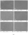
- Fig. depicts in a) to c) a surface morphology obtained by processes according to the invention, and in d) to f) a surface morphology obtained by a process according to the comparative examples.
- An aircraft part such as a structural part, that is preferably made of AA2024 alloy and cladded with a commercially pure aluminium grade, is pretreated by degreasing in an alkaline cleaner for 15 minutes at 60 °C. Subsequently, alkaline etching for 1 minute at 60°C was performed. Finally, the panels have been desmutted in a fluoride containing acidic pickling solution for 5 minutes at 35°C. Between each of these pre-treatment steps (degreasing, etching and pickling), the part has been rinsed in agitated deionized water at room temperature for three minutes.
- Sulphuric acid with a concentration of 40 g/l is prepared as an anodising electrolyte.
- the anodising electrolyte is maintained at a temperature of 45 °C.
- An anodising voltage is ramped up to 14 V over a time period of 1 minute and kept at 14 V for a time period of 10 minutes.
- Example 1 The process according to Example 1 is repeated with the anodising electrolyte being maintained at a temperature of 37 °C.
- the part is exposed to the anodising electrolyte.
- the anodising voltage is ramped up to 20 V over a time period of 1 minute and kept at 20 V for a time period of 8 minutes.
- Example 1 The process according to Example 1 is repeated with the anodising electrolyte being prepared from a mixture of sulphuric acid with a concentration of 40 g/l and tartaric acid with a concentration of 80 g/l.
- the anodising electrolyte is maintained at a temperature of 55 °C.
- the part is exposed to the anodising electrolyte.
- the anodising voltage is ramped up to 14 V over a time period of 1 minute and kept at 14 V for a time period of 8 minutes.
- Example 2 The process according to Example 2 is repeated with the anodising electrolyte being maintained at a temperature of 37 °C.
- the part is exposed to the anodising electrolyte.
- the anodising voltage is ramped up to 20 V over a time period of 1 minute and kept at 20 V for a time period of 9 minutes.
- Example 1 The process according to Example 1 is repeated with the anodising electrolyte being prepared from a mixture of sulphuric acid with a concentration of 40 g/l and tartaric acid with a concentration of 150 g/l.
- the anodising electrolyte is maintained at a temperature of 55 °C.
- the part is exposed to the anodising electrolyte.
- the anodising voltage is ramped up to 14 V over a time period of 1 minute and kept at 14 V for a time period of 10 minutes.
- Example 3 The process according to Example 3 is repeated with the anodising electrolyte being maintained at a temperature of 37 °C.
- the part is exposed to the anodising electrolyte.
- the anodising voltage is ramped up to 20 V over a time period of 1 minute and kept at 20 V for a time period of 10 minutes.
- the anodised part surface is coated with an organic coating.
- a Cr(VI)-free inhibited solvent-based epoxy model primer was applied to the samples by spraying targeting a coating thickness of 20 ⁇ m ( ⁇ 5 ⁇ m).
- a compatible epoxy topcoat layer was applied on the panels intended for the filiform corrosion (FFT) experiment on top of the model primer, targeting a coating thickness of 25 ⁇ m ( ⁇ 5 ⁇ m).
- coated parts have been artificially damaged using two crossing u-shaped scribes forming an X on the surface.
- the scribes are 1 mm wide and have a depth between 200 ⁇ m and 300 ⁇ m, ensuring that the damage penetrates through the paint, oxide and cladding, thus reaching the substrate alloy. This procedure is defined in the ISO 17872 standard.
- the scribes have been created by a rotating saw.
- the panels Shortly after scribing, the panels have been transferred to a neutral salt spray test chamber according to ISO 9227 for 3000 hours. A visual inspection was carried out after 168 h, 336 h, 500 h, 1000 h, 2000 h and 3000 h. In this inspection, attention is given to changes in the scribe colour (tarnishing), the appearance of pits, the presence of corrosion products, paint discoloration and the length of the paint creepage, which is measured starting from the artificial defect.
- Table 1 shows the average (over three samples) of the maximum paint creepage after 3000 hours in a neutral salt spray test.
- SAA designates regular concentration sulfuric acid anodisation
- TSA and T+SA designate tartaric and sulfuric acid anodisation
- the "+" designates a concentration of tartaric acid of 150 g/l.
- the panels were pre-exposed to hydrochloric acid vapour for one hour.
- the samples were then transferred to a cabinet at 40°C and 82% relative humidity for 1000 hours.
- Visual inspections were carried out after 168 h, 336 h, 500 h, 750 h and 1000 h. In each of these inspections, the lengths of the 5 longest filaments were noted.
- some selected specimens have been automatically assessed by a Shufter + Kirchhoff corrosion inspector scanner and the associated automatic image processing software to further increase the statistical relevance of the obtained results.
- the filiform corrosion test is typically assessed by measuring the five longest filaments per sample, and averaging the results.
- the results obtained by this principle, considering three samples per anodising condition, at the different inspection times during the 1000 h filiform corrosion test are shown in subsequent Table 2. These results show similar filament lengths for all test panels, regardless of the anodising process parameters used.
- the appearance of the filaments is dependent on the anodising parameters, particularly on the anodising temperature.
- the filaments are significantly thinner for those samples anodised according to the invention.
- the average filament area has been measured using an FFT scanner coupled with automated image processing software. The results obtained, summarized in the last two rows in Table 2, confirm the qualitative observation, showing smaller average filiform areas for those substrates anodised at elevated temperatures (45°C or 55°C).
- Adhesion performance was assessed using ISO 2409 standard for the cross-cut adhesion between a substrate and organic coating.
- the thickness of the coating was measured by eddy current.
- six parallel cuts, at a distance of 1 mm from each other are performed in two perpendicular directions forming a lattice.
- the cuts have been done by a motor-driven single blade at a constant force.
- the force applied was chosen to ensure complete penetration of the cutting blade through the organic coating.
- the lattice area is softly cleaned with a brush to remove any coating debris and a pressure sensitive tape (TESA 4651) is applied covering the lattice (test area).
- the tape is rapidly removed and the visual appearance of the test area is assessed according to the grading system described in the ISO 2409 standard.
- the test has been conducted on dry samples, as well as on samples that were immersed in deionised water for two weeks.
- a cross-cut adhesion test (ISO 2409) has been conducted to assess the adhesion properties of the anodic oxide films under study in combination with a Cr(VI)-free model primer in dry conditions and after two weeks of immersion in deionised water. All samples show good adhesion (see subsequent Table 3), with no failure at all or only small delamination ( ⁇ 5% of the total area of study) at the cutting intersections. This is the case regardless of the anodising electrolyte used.
- the morphological characterisation of the oxide films reveals an important influence of the electrolyte temperature in terms of porosity and ultimate surface roughness.
- the higher anodising temperatures according to the invention lead to an enhanced oxide dissolution, especially in the uppermost area of the oxide, which is in contact with the anodising electrolyte for the entire anodising time.
- the pore mouths are wider and even coalesce and at the same time the ultimate surface becomes rougher, in comparison to the narrow-pores and smooth surfaces seen on the oxides formed at a lower temperature according to the Comparative Examples 1 to 3.
- the electrolyte chemistry has also an effect on the porosity of the resulting oxide films, with SAA films showing higher porosity values at the surface of the anodic oxide. It has been previously reported that the addition of tartaric acid to a sulfuric acid electrolyte leads to a reduction of the dissolution reaction rate. Hence pore mouth widening through oxide dissolution is less significant in tartaric acid containing electrolytes. Finally, even though the formation voltage did not have a significant impact in the morphological analysis and as previously studied by the inventors, it is widely accepted that the barrier layer thickness is proportional to the formation voltage. Therefore, even though the barrier layer thickness has not been directly characterised in our study, it can be assumed that the barrier layer of the anodic oxide films formed at 20 V is thicker than for the oxides formed at 14 V.
- increasing the concentration of tartaric acid may substantially increase the time to pitting, while anodising at a lower temperature (37 vs. 55°C) and at a higher voltage (20 vs. 14 V) may slightly improve the pitting resistance of the resulting oxides.
- tartaric acid to the anodising electrolyte also has a positive effect on the resistance of the anodic oxide film against dissolution, especially in the acidified corrosive solution and to a certain extent also in an alkaline environment.
- TSA/T + SA oxide films are certainly contributing to its corrosion resistance, whereas the enhanced barrier properties due to a thicker barrier layer could be responsible for the trend of improved pitting resistance at higher formation voltages.
- anodic oxide films are typically covered by an organic coating loaded with corrosion inhibitors. Therefore, standard corrosion and adhesion tests of anodised and coated specimens have been performed.
- the resistance to pitting corrosion and the oxide degradation behaviour of bare anodic oxide films have been studied as a function of anodising parameters.
- the enhanced resistance against pitting corrosion and against degradation in acidic solutions of the bare oxides formed in the presence of tartaric acid highlight the benefits of mixed sulfuric-tartaric acid electrolyte anodising processes.
- the anodising temperature and formation voltage play a minor role in comparison to the tartaric acid concentration, a tendency towards better pitting resistance is observed if anodised at lower electrolyte temperatures and higher voltages.
- the corrosion protection performance is dominated by the anodising electrolyte temperature that creates optimal morphological features for enhanced coating adhesion, whereas the effect of the anodising voltage and of the anodising electrolyte is concealed by the effect of temperature.
Landscapes
- Chemical & Material Sciences (AREA)
- Materials Engineering (AREA)
- Engineering & Computer Science (AREA)
- Organic Chemistry (AREA)
- Electrochemistry (AREA)
- Metallurgy (AREA)
- Chemical Kinetics & Catalysis (AREA)
- Inorganic Chemistry (AREA)
- Life Sciences & Earth Sciences (AREA)
- Wood Science & Technology (AREA)
- General Chemical & Material Sciences (AREA)
- Application Of Or Painting With Fluid Materials (AREA)
- Chemical Treatment Of Metals (AREA)
Abstract
Description
- The invention relates to a method for anodising a part surface of a part, preferably an aircraft part, and a method for coating a part surface. Further the invention relates to a part obtainable by said method and an aircraft equipped with said part.
- Traditionally aluminium parts in the aerospace industry have been anodised in chromic acid (chromic acid anodisation, short: CAA). CAA was both used for corrosion protection of painted structural aluminium parts and as a pretreatment prior to bonding for parts joined by structural bonding. While the corrosion protection and adhesion properties of anodic oxide films obtained by this process were outstanding, the health hazard of hexavalent chromium led to its substitution.
- In the 2000s decade tartaric-sulfuric acid anodising (TSA) was introduced as a substitution of CAA for corrosion protection purposes (painted parts, unpainted parts). The anodic films produced by the TSA process are usually not suitable for bonding applications. The resulting anodic oxide film of the TSA process is a porous structure with a smooth oxide surface, and with narrow pores. The narrow pores are suitable for sealing steps, providing corrosion protection for unpainted parts. In unsealed condition, the pores provide good adhesion for paint. The TSA process was developed and qualified with conventional, Cr(VI)-loaded basic primers that were available at that time and that are still in use.
- For other kinds of paints, such as Cr(VI)-free basic primers that are currently known, an adaption of parameters of the TSA process, aiming at an improved adhesion of the new paints and an improved corrosion protection performance of the full stack, could be key to enable their widespread introduction as a standard.
-
DE 103 61 888 B3 discloses a method for applying an anodizing layer to the surface of components made of aluminum materials. The workpiece to be treated is introduced successively into two different electrolytes, each consisting of at least two components, and its surface is oxidized while applying a DC voltage. In the first anodizing step, the electrolyte consists of an inorganic mixed acid, while in the second anodizing step a mixture of an organic and an inorganic acid is used. -
EP 1 233 084 A2 discloses a process for anodizing a workpiece of aluminium or aluminium alloys in the presence of an aqueous acid solution which contains from 10 g to 200 g sulphuric acid and from 5 to 200 g L(+)-tartaric acid. -
EP 2 055 810 A2 andUS 2009 / 0 107 848 A1 disclose a procedure for anodising aluminium or aluminium alloys in which an aluminium or an aluminium alloy part is submerged an in an aqueous solution at a temperature between 0°C and 140°C, preferably between 0°C and 130°C, in which the solution includes sulphuric acid, tartaric acid, and at least one inorganic salt of an element selected between at least one transition metal, a lanthanide element, an actinide, and combinations of them, and applying a controlled potential difference, obtaining layers of aluminium oxide with properties as good as or even better than those obtained through anodising in traditional chromic acid solutions. - The introduction of Cr(VI)-free paints poses a challenge to enhance the corrosion protection provided by the underlying anodic oxide film and to better understand the interaction between the anodic oxide film and the corrosion inhibiting paint.
- It is the object of the invention to allow for an improved corrosion protection with Cr(VI)-free paints.
- The object is achieved by the subject-matter of the independent claims. Preferred embodiments are subject matter of the dependent claims.
- The invention provides a method for anodising a part surface of a part, preferably an aircraft part, the surface including aluminium or an aluminium alloy, the method comprising:
- a) cleaning the part surface to obtain a cleaned part surface;
- b) preparing an anodising electrolyte, the anodising electrolyte being chosen from a group consisting of sulfuric acid, and a mixture of sulfuric and tartaric acid; and
- c) exposing the cleaned part surface to the anodising electrolyte and applying an anodising voltage so as to form an anodised layer on the part surface, wherein, at least when the anodising voltage is applied, the anodising electrolyte is maintained at a constant temperature chosen from a range from 42 °C to 60 °C.
- Preferably, in step c) the temperature is chosen from a range from 43 °C to 47 °C or from 52 °C to 57 °C. Preferably, in step c) the temperature is chosen from a range from (45 ± 1) °C or from (55 ± 1) °C.
- Preferably, in step b) the anodising electrolyte is sulfuric acid. Preferably, the sulfuric acid has a concentration of 30 g/l to 50 g/l. Preferably, the sulfuric acid has a concentration of 36 g/l to 44 g/l. Preferably, the sulfuric acid has a concentration of 38 g/l to 42 g/l, more preferably (40 ± 1) g/l.
- Preferably, in step b) the anodising electrolyte is the mixture of sulfuric acid and tartaric acid. Preferably, the sulfuric acid has a concentration of 30 g/l to 130 g/l. Preferably, the sulfuric acid has a concentration of 36 g/l to 44 g/l. Preferably, the sulfuric acid has a concentration of 38 g/l to 42 g/l. Preferably, the sulfuric acid has a concentration of (40 ± 1) g/l.
- Preferably, the tartaric acid has a concentration of 40 g/l to 100 g/l. Preferably, the tartaric acid has a concentration of 70 g/l to 90 g/l. Preferably, the tartaric acid has a concentration of 78 g/l to 82 g/l. Preferably, the tartaric acid has a concentration of (80 ± 1) g/l.
- Preferably, in step b) the anodising electrolyte is the mixture of sulfuric acid and tartaric acid. Preferably, the sulfuric acid has a concentration of 30 g/l to 130 g/l. Preferably, the sulfuric acid has a concentration of 36 g/l to 44 g/l. Preferably, the sulfuric acid has a concentration of 38 g/l to 42 g/l. Preferably, the sulfuric acid has a concentration of (40 ± 1) g/l. Preferably, the tartaric acid has a concentration of 130 g/l to 170 g/l. Preferably, the tartaric acid has a concentration of 140 g/l to 160 g/l. Preferably, the tartaric acid has a concentration of 145 g/l to 155 g/l. Preferably, the tartaric acid has a concentration of (150 ± 1) g/l.
- Preferably, in step c) the anodising voltage is ramped up to a value of 10 V to 25 V in a time period of 0.5 min to 2 min and kept constant for a time period of 8 min to 12 min.
- Preferably, the anodising voltage is ramped up to a value of 12 V to 14 V, preferably to a value of 14 V, more preferably to a value of 14.0 V. Preferably, the anodising voltage is kept constant for a time period of 8 min to 10 min, preferably for a time period of 8.0 min to 10.0 min, more preferably for a time period of 8.0 min or of 10.0 min.
- Preferably, step a) comprises a1) degreasing the part surface to obtain a degreased part surface.
- Preferably, step a) comprises a2) alkaline etching of the degreased part surface to obtain an etched part surface.
- Preferably, step a) comprises a3) pickling the etched part surface with an acidic pickling solution.
- Preferably, step a) comprises a4) rinsing the part surface between any of the steps a1) to a3) and/or after step a3).
- The invention provides a method for coating a part surface of a part, preferably an aircraft part, with a corrosion protection layer, the method comprising:
- a) performing a previously described method so as to obtain a anodised layer;
- b) applying a primer layer made of Cr(VI)-free epoxy model primer on the anodised layer; and optionally
- c) applying a topcoat layer made of a compatible epoxy topcoat.
- The invention provides a part, preferably an aircraft part obtainable by a preferred method, and an aircraft comprising the aircraft part.
- The invention relates to surface engineering, in particular to the field of corrosion protection of structural aerospace aluminium alloys. The ideas described herein can be generally applied to all aluminium parts that require a surface treatment for corrosion protection (e.g. all parts that are currently anodised for corrosion protection purposes) It should be noted that these ideas are not necessarily applicable to parts anodised for bonding purposes.
- Experiments of the inventors surprisingly found that there exists a range of temperatures in which a specific surface morphology is obtained, which enhances adhesion. This range of temperatures is dependent on the anodising electrolyte chemical composition.
- Furthermore, samples anodised in this particular range of temperatures and subsequently painted with a corrosion inhibiting paint show better corrosion protection performance in standard corrosion testing (neutral salt spray test, filiform corrosion test). This is the case, even when the corrosion resistance of the bare (not-painted) samples anodised in this particular range of temperatures was lower than that of the reference process.
- This process allows for the enhancement of paint adhesion and corrosion protection performance. The new TSA process may serve as an enabler for new paint schemes such as Cr(VI)-free basic primers. Furthermore, these ideas may enable the introduction of innovative coating solutions beyond conventional paints (e.g. powder coatings, bio-based coatings). An improved corrosion protection performances reduces the need for maintenance and repairs associated with corrosion processes of anodised and painted aluminium parts.
- A characteristic oxide morphology at the ultimate surface of the anodic oxide film is obtained at those temperatures. Widening of the pore mouths and the creation of a rougher surface is observed.
- The samples with an anodic oxide film with the above mentioned morphological features in combination with a corrosion inhibiting paint outperform all the other samples, including the reference sample prepared according to the standard TSA process. All the other samples tested were anodised at 37°C and did not show this distinct surface morphology.
- The only Fig. depicts in a) to c) a surface morphology obtained by processes according to the invention, and in d) to f) a surface morphology obtained by a process according to the comparative examples.
- An aircraft part, such as a structural part, that is preferably made of AA2024 alloy and cladded with a commercially pure aluminium grade, is pretreated by degreasing in an alkaline cleaner for 15 minutes at 60 °C. Subsequently, alkaline etching for 1 minute at 60°C was performed. Finally, the panels have been desmutted in a fluoride containing acidic pickling solution for 5 minutes at 35°C. Between each of these pre-treatment steps (degreasing, etching and pickling), the part has been rinsed in agitated deionized water at room temperature for three minutes.
- Sulphuric acid with a concentration of 40 g/l is prepared as an anodising electrolyte. The anodising electrolyte is maintained at a temperature of 45 °C.
- The part is exposed to the anodising electrolyte. An anodising voltage is ramped up to 14 V over a time period of 1 minute and kept at 14 V for a time period of 10 minutes.
- The process according to Example 1 is repeated with the anodising electrolyte being maintained at a temperature of 37 °C.
- The part is exposed to the anodising electrolyte. The anodising voltage is ramped up to 20 V over a time period of 1 minute and kept at 20 V for a time period of 8 minutes.
- The process according to Example 1 is repeated with the anodising electrolyte being prepared from a mixture of sulphuric acid with a concentration of 40 g/l and tartaric acid with a concentration of 80 g/l. The anodising electrolyte is maintained at a temperature of 55 °C.
- The part is exposed to the anodising electrolyte. The anodising voltage is ramped up to 14 V over a time period of 1 minute and kept at 14 V for a time period of 8 minutes.
- The process according to Example 2 is repeated with the anodising electrolyte being maintained at a temperature of 37 °C.
- The part is exposed to the anodising electrolyte. The anodising voltage is ramped up to 20 V over a time period of 1 minute and kept at 20 V for a time period of 9 minutes.
- The process according to Example 1 is repeated with the anodising electrolyte being prepared from a mixture of sulphuric acid with a concentration of 40 g/l and tartaric acid with a concentration of 150 g/l. The anodising electrolyte is maintained at a temperature of 55 °C.
- The part is exposed to the anodising electrolyte. The anodising voltage is ramped up to 14 V over a time period of 1 minute and kept at 14 V for a time period of 10 minutes.
- The process according to Example 3 is repeated with the anodising electrolyte being maintained at a temperature of 37 °C.
- The part is exposed to the anodising electrolyte. The anodising voltage is ramped up to 20 V over a time period of 1 minute and kept at 20 V for a time period of 10 minutes.
- The anodised part surface is coated with an organic coating. A Cr(VI)-free inhibited solvent-based epoxy model primer was applied to the samples by spraying targeting a coating thickness of 20 µm (± 5 µm). A compatible epoxy topcoat layer was applied on the panels intended for the filiform corrosion (FFT) experiment on top of the model primer, targeting a coating thickness of 25 µm (± 5 µm).
- To study corrosion in the presence of a physical defect, coated parts have been artificially damaged using two crossing u-shaped scribes forming an X on the surface. The scribes are 1 mm wide and have a depth between 200 µm and 300 µm, ensuring that the damage penetrates through the paint, oxide and cladding, thus reaching the substrate alloy. This procedure is defined in the ISO 17872 standard. The scribes have been created by a rotating saw.
- Shortly after scribing, the panels have been transferred to a neutral salt spray test chamber according to ISO 9227 for 3000 hours. A visual inspection was carried out after 168 h, 336 h, 500 h, 1000 h, 2000 h and 3000 h. In this inspection, attention is given to changes in the scribe colour (tarnishing), the appearance of pits, the presence of corrosion products, paint discoloration and the length of the paint creepage, which is measured starting from the artificial defect.
- The subsequent Table 1 shows the average (over three samples) of the maximum paint creepage after 3000 hours in a neutral salt spray test. As a general trend, the best results (smaller paint creepage length) are obtained for the samples anodised according to the invention at temperatures above 42 °C. SAA designates regular concentration sulfuric acid anodisation, TSA and T+SA designate tartaric and sulfuric acid anodisation, wherein the "+" designates a concentration of tartaric acid of 150 g/l.
Table 1 Exposure time [h] Paint creepage Anodising parameters SAA 14 V 45°C SAA 20 V 37°C TSA 14 V 55 °C TSA 20 V 37°C T+SA 14 V 55°C T+SA 20 V 37°C 3000 h Length [mm] 1.5 2.4 1.7 3.1 1.8 4.2 SD [mm] 0.1 0.6 0.6 0.8 0.5 0.4 - The ability of the corrosion protection scheme (anodic oxide film + primer + topcoat) to prevent filiform corrosion has been studied according to the EN3665 standard. For this purpose, samples have been scribed according to ISO 17872, in the same way as for the NSST samples.
- Shortly after scribing, the panels were pre-exposed to hydrochloric acid vapour for one hour. The samples were then transferred to a cabinet at 40°C and 82% relative humidity for 1000 hours. Visual inspections were carried out after 168 h, 336 h, 500 h, 750 h and 1000 h. In each of these inspections, the lengths of the 5 longest filaments were noted. After the test, some selected specimens have been automatically assessed by a Schäfter + Kirchhoff corrosion inspector scanner and the associated automatic image processing software to further increase the statistical relevance of the obtained results.
- The filiform corrosion test is typically assessed by measuring the five longest filaments per sample, and averaging the results. The results obtained by this principle, considering three samples per anodising condition, at the different inspection times during the 1000 h filiform corrosion test are shown in subsequent Table 2. These results show similar filament lengths for all test panels, regardless of the anodising process parameters used.
- However, while the filament length is similar, the appearance of the filaments is dependent on the anodising parameters, particularly on the anodising temperature. The filaments are significantly thinner for those samples anodised according to the invention. To better quantify this observation the average filament area has been measured using an FFT scanner coupled with automated image processing software. The results obtained, summarized in the last two rows in Table 2, confirm the qualitative observation, showing smaller average filiform areas for those substrates anodised at elevated temperatures (45°C or 55°C).
Table 2 Exposure time [h] Filament Anodising parameters SAA 14 V 45°C SAA 20 V 37°C TSA 14 V 55 °C TSA 20 V 37°C T+SA 14 V 55°C T+SA 20 V 37°C 168 Length [mm] 0.6 0.8 0.6 0.7 0.7 0.7 SD [mm] 0.1 0.1 0.1 0.2 0.2 0.2 336 Length [mm] 1.0 1.0 1.0 1.0 1.1 1.0 SD [mm] 0.1 0.2 0.2 0.1 0.2 0.1 500 Length [mm] 1.0 1.1 1.0 1.1 1.2 1.1 SD [mm] 0.1 0.2 0.2 0.1 0.2 0.2 750 Length [mm] 1.2 1.2 1.2 1.1 1.4 1.3 SD [mm] 0.3 0.3 0.2 0.1 0.3 0.2 1000 Length [mm] 1.4 1.3 1.3 1.4 1.5 1.3 SD [mm] 0.2 0.3 0.2 0.1 0.3 0.2 Area [mm2] 4.8 5.6 3.9 5.7 5.2 6.5 SD [mm2] 0.8 1.0 0.9 1.3 1.2 1.7 - Adhesion performance was assessed using ISO 2409 standard for the cross-cut adhesion between a substrate and organic coating. First, the thickness of the coating was measured by eddy current. Then, six parallel cuts, at a distance of 1 mm from each other are performed in two perpendicular directions forming a lattice. In this particular case, the cuts have been done by a motor-driven single blade at a constant force. The force applied was chosen to ensure complete penetration of the cutting blade through the organic coating. The lattice area is softly cleaned with a brush to remove any coating debris and a pressure sensitive tape (TESA 4651) is applied covering the lattice (test area). The tape is rapidly removed and the visual appearance of the test area is assessed according to the grading system described in the ISO 2409 standard. In order to assess the adhesion stability of the coating in the presence of moisture, the test has been conducted on dry samples, as well as on samples that were immersed in deionised water for two weeks.
- A cross-cut adhesion test (ISO 2409) has been conducted to assess the adhesion properties of the anodic oxide films under study in combination with a Cr(VI)-free model primer in dry conditions and after two weeks of immersion in deionised water. All samples show good adhesion (see subsequent Table 3), with no failure at all or only small delamination (< 5% of the total area of study) at the cutting intersections. This is the case regardless of the anodising electrolyte used. These results indicate that, even though the cross cut adhesion test is widely used for the assessment of coating adhesion, it is not sensitive enough to capture the differences in adhesion properties among anodic oxide films.
Table 3 Anodising Parameters Dry Adhesion Wet Adhesion SAA 14 V 45°C No failure No failure SAA 20 V 37°C No failure No failure TSA 14 V 55°C No failure No failure TSA 20 V 37°C No failure Delamination < 5 % of area T+SA 14 V 55°C No failure No failure T+SA 20 V 37°C No failure Delamination < 5 % of area - The morphological characterisation of the oxide films reveals an important influence of the electrolyte temperature in terms of porosity and ultimate surface roughness. The higher anodising temperatures according to the invention lead to an enhanced oxide dissolution, especially in the uppermost area of the oxide, which is in contact with the anodising electrolyte for the entire anodising time. As a consequence, the pore mouths are wider and even coalesce and at the same time the ultimate surface becomes rougher, in comparison to the narrow-pores and smooth surfaces seen on the oxides formed at a lower temperature according to the Comparative Examples 1 to 3.
- To a lesser extent, the electrolyte chemistry has also an effect on the porosity of the resulting oxide films, with SAA films showing higher porosity values at the surface of the anodic oxide. It has been previously reported that the addition of tartaric acid to a sulfuric acid electrolyte leads to a reduction of the dissolution reaction rate. Hence pore mouth widening through oxide dissolution is less significant in tartaric acid containing electrolytes. Finally, even though the formation voltage did not have a significant impact in the morphological analysis and as previously studied by the inventors, it is widely accepted that the barrier layer thickness is proportional to the formation voltage. Therefore, even though the barrier layer thickness has not been directly characterised in our study, it can be assumed that the barrier layer of the anodic oxide films formed at 20 V is thicker than for the oxides formed at 14 V.
- In terms of oxide chemistry, no significant differences could be measured, neither by XPS nor by ToF-SIMS, regardless of the electrolyte chemistry, the formation voltage and the anodising temperature. In particular no evidence of tartrate incorporation could be found.
- Chronoamperometry investigations revealed that the resistance to pitting behaviour of anodic oxide films formed in a tartaric-acid containing electrolyte is better than for SAA oxides. This is derived from the fact that the time under galvanic stress until a significant rise in current density takes place is longer for TSA and T+SA oxides. This is in line with known art, where anodic oxide films formed in chromic acid, sulfuric acid and in several mixed sulfuric acid-organic acid electrolytes, among them tartaric acid, were compared. Furthermore, the present invention demonstrates that aside from the type of electrolyte, the pitting behaviour is also affected by the tartaric acid concentration the electrolyte temperature and the anodising voltage. In fact, increasing the concentration of tartaric acid may substantially increase the time to pitting, while anodising at a lower temperature (37 vs. 55°C) and at a higher voltage (20 vs. 14 V) may slightly improve the pitting resistance of the resulting oxides.
- The addition of tartaric acid to the anodising electrolyte also has a positive effect on the resistance of the anodic oxide film against dissolution, especially in the acidified corrosive solution and to a certain extent also in an alkaline environment. However, there is no clear trend correlating the electrolyte temperature and formation voltage with the resistance in the alkaline and acid corrosive solution.
- Taking into account the almost identical oxide chemical composition for all studied conditions, the differences in pitting susceptibility and pH stability among bare anodic oxide films is attributed to their morphology.
- The reduced porosity of TSA/T+SA oxide films is certainly contributing to its corrosion resistance, whereas the enhanced barrier properties due to a thicker barrier layer could be responsible for the trend of improved pitting resistance at higher formation voltages.
- Although the resistance of the bare anodic oxide films provides a way of comparison between the different processes and may be relevant in a few particular applications, in practice anodic oxide films are typically covered by an organic coating loaded with corrosion inhibitors. Therefore, standard corrosion and adhesion tests of anodised and coated specimens have been performed.
- In spite of the thicker barrier layer associated with a higher anodising voltage and the higher pitting corrosion and acidic resistance reported in the present study for TSA and T+SA bare oxides, the corrosion test results show better performance of the coated specimens that underwent higher-temperature anodising processes (45 and 55°C) according to the invention, regardless of the electrolyte chemistry and formation voltage. The wider pore mouths and rougher surface of the oxide films anodised at an elevated temperature promote mechanical interlocking and consequently adhesion. Therefore, it can be concluded that the enhanced stability at the coating/oxide interface plays a critical role in the NSST and FFT results.
- The effect of the electrolyte chemistry, the electrolyte temperature and the formation voltage on the resulting anodic oxide morphology and chemistry has been studied. The addition of tartaric acid to a sulfuric acid electrolyte leads to a slight reduction in porosity. Wider pore mouths and dissolution driven roughness are the result of anodising at elevated temperatures while the effect of the formation voltage on the characterised morphological features is not significant. The chemical composition of the surface of the anodic oxide films is almost identical regardless of anodising parameters.
- The resistance to pitting corrosion and the oxide degradation behaviour of bare anodic oxide films have been studied as a function of anodising parameters. The enhanced resistance against pitting corrosion and against degradation in acidic solutions of the bare oxides formed in the presence of tartaric acid highlight the benefits of mixed sulfuric-tartaric acid electrolyte anodising processes. Although the anodising temperature and formation voltage play a minor role in comparison to the tartaric acid concentration, a tendency towards better pitting resistance is observed if anodised at lower electrolyte temperatures and higher voltages.
- Finally, in combination with a corrosion inhibiting organic coating, the corrosion protection performance is dominated by the anodising electrolyte temperature that creates optimal morphological features for enhanced coating adhesion, whereas the effect of the anodising voltage and of the anodising electrolyte is concealed by the effect of temperature.
Claims (11)
- A method for anodising a part surface of a part, preferably an aircraft part, the surface including aluminium or an aluminium alloy, the method comprising:a) cleaning the part surface to obtain a cleaned part surface;b) preparing an anodising electrolyte, the anodising electrolyte being chosen from a group consisting of sulfuric acid, and a mixture of sulfuric and tartaric acid; andc) exposing the cleaned part surface to the anodising electrolyte and applying an anodising voltage so as to form an anodised layer on the part surface, wherein, at least when the anodising voltage is applied, the anodising electrolyte is maintained at a constant temperature chosen from a range from 42 °C to 60 °C.
- The method according to claim 1, wherein in step c) the temperature is chosen from a range from 43 °C to 47 °C or from 52 °C to 57 °C, preferably from (45 ± 1) °C or from (55 ± 1) °C.
- The method according to any of the preceding claims, wherein in step b) the anodising electrolyte is sulfuric acid having a concentration of 30 g/l to 50 g/l, preferably 36 g/l to 44 g/l, more preferably 38 g/l to 42 g/l, more preferably (40 ± 1) g/l.
- The method according to claim 1 or 2, wherein in step b) the anodising electrolyte is the mixture of sulfuric acid and tartaric acid, and the sulfuric acid has a concentration of 30 g/l to 130 g/l, preferably 36 g/l to 44 g/l, more preferably 38 g/l to 42 g/l, more preferably (40 ± 1) g/l, and the tartaric acid has a concentration of 40 g/l to 100 g/l, preferably 70 g/l to 90 g/l, more preferably 78 g/l to 82 g/l, more preferably (80 ± 1) g/l.
- The method according to claim 1 or 2, wherein in step b) the anodising electrolyte is the mixture of sulfuric acid and tartaric acid, and the sulfuric acid has a concentration of 30 g/l to 130 g/l, preferably 36 g/l to 44 g/l, more preferably 38 g/l to 42 g/l, more preferably (40 ± 1) g/l, and the tartaric acid has a concentration of 130 g/l to 170 g/l, preferably 140 g/l to 160 g/l, more preferably 145 g/l to 155 g/l, more preferably (150 ± 1) g/l.
- The method according to any of the preceding claims, wherein in step c) the anodising voltage is ramped up to a value of 10 V to 25 V in a time period of 0.5 min to 2 min and kept constant for a time period of 8 min to 12 min.
- The method according to claim 6, wherein the anodising voltage is ramped up to a value of 12 V to 14 V, preferably to a value of 14 V, more preferably to a value of 14.0 V, and kept constant for a time period of 8 min to 10 min, preferably for a time period of 8.0 min to 10.0 min, more preferably for a time period of 8.0 min or of 10.0 min.
- The method according to any of the preceding claims, wherein step a) comprises at least one of:a1) degreasing the part surface to obtain a degreased part surface; and/ora2) alkaline etching of the degreased part surface to obtain an etched part surface; and/ora3) pickling the etched part surface with an acidic pickling solution; and/ora4) rinsing the part surface between any of the steps a1) to a3) and/or after step a3).
- A method for coating a part surface of a part, preferably an aircraft part, with a corrosion protection layer, the method comprising:a) performing a method according to any of the preceding claims so as to obtain a anodised layer;b) applying a primer layer made of Cr(VI)-free epoxy model primer on the anodised layer; and optionallyc) applying a topcoat layer made of a compatible epoxy topcoat.
- A part, preferably an aircraft part obtainable by a method according to any of the preceding claims.
- An aircraft comprising an aircraft part according to claim 10.
Priority Applications (3)
| Application Number | Priority Date | Filing Date | Title |
|---|---|---|---|
| EP22170800.1A EP4269662A1 (en) | 2022-04-29 | 2022-04-29 | Methods for anodizing a part surface and subsequently coating the anodized part surface for corrosion protection purposes |
| US18/307,867 US20240167186A1 (en) | 2022-04-29 | 2023-04-27 | Methods for anodizing a part surface and subsequently coating the anodized part surface for corrosion protection purposes |
| CN202310468638.7A CN116971009A (en) | 2022-04-29 | 2023-04-27 | Method for anodizing the surface of a component and subsequent coating for corrosion protection |
Applications Claiming Priority (1)
| Application Number | Priority Date | Filing Date | Title |
|---|---|---|---|
| EP22170800.1A EP4269662A1 (en) | 2022-04-29 | 2022-04-29 | Methods for anodizing a part surface and subsequently coating the anodized part surface for corrosion protection purposes |
Publications (1)
| Publication Number | Publication Date |
|---|---|
| EP4269662A1 true EP4269662A1 (en) | 2023-11-01 |
Family
ID=81448366
Family Applications (1)
| Application Number | Title | Priority Date | Filing Date |
|---|---|---|---|
| EP22170800.1A Pending EP4269662A1 (en) | 2022-04-29 | 2022-04-29 | Methods for anodizing a part surface and subsequently coating the anodized part surface for corrosion protection purposes |
Country Status (3)
| Country | Link |
|---|---|
| US (1) | US20240167186A1 (en) |
| EP (1) | EP4269662A1 (en) |
| CN (1) | CN116971009A (en) |
Citations (9)
| Publication number | Priority date | Publication date | Assignee | Title |
|---|---|---|---|---|
| CN1106865A (en) * | 1994-02-04 | 1995-08-16 | 大连星光电磁铁厂 | Aluminium foil anodic oxidation electrolyte solution for electric appliance |
| EP1233084A2 (en) | 2001-02-20 | 2002-08-21 | Alenia Aeronautica S.P.A. | "Anodizing process, with low environmental impact, for a workpiece of aluminium or aluminium alloys" |
| DE10361888B3 (en) | 2003-12-23 | 2005-09-22 | Airbus Deutschland Gmbh | Anodizing process for aluminum materials |
| US20090107848A1 (en) | 2007-10-29 | 2009-04-30 | Pilar Ocon Esteban | Procedure for anodising aluminium or aluminium alloys |
| US20160194779A1 (en) * | 2013-12-06 | 2016-07-07 | Kabushiki Kaisha Toyota Chuo Kenkyusho | Metal-resin composite material, method for producing the same, and aluminum substrate having aluminum oxide coating |
| CN106757264A (en) * | 2016-11-23 | 2017-05-31 | 南昌航空大学 | A kind of aluminum alloy environment-friendly type temperature anodic oxidation electrolyte wide and method for oxidation |
| US20190112725A1 (en) * | 2016-04-18 | 2019-04-18 | Fokker Aerostructures B.V. | Anodizing an article of aluminum or alloy thereof |
| CN110965104A (en) * | 2019-11-18 | 2020-04-07 | 重庆理工大学 | Normal-temperature sealing treatment method for Al-Cu-Li alloy anodic oxide film |
| EP3696299A1 (en) * | 2019-02-15 | 2020-08-19 | Coventya GmbH | Method for producing a corrosion-resistant aluminum-silicon alloy casting, corresponding corrosion-resistant aluminum-silicon alloy casting and its use |
-
2022
- 2022-04-29 EP EP22170800.1A patent/EP4269662A1/en active Pending
-
2023
- 2023-04-27 CN CN202310468638.7A patent/CN116971009A/en active Pending
- 2023-04-27 US US18/307,867 patent/US20240167186A1/en active Pending
Patent Citations (10)
| Publication number | Priority date | Publication date | Assignee | Title |
|---|---|---|---|---|
| CN1106865A (en) * | 1994-02-04 | 1995-08-16 | 大连星光电磁铁厂 | Aluminium foil anodic oxidation electrolyte solution for electric appliance |
| EP1233084A2 (en) | 2001-02-20 | 2002-08-21 | Alenia Aeronautica S.P.A. | "Anodizing process, with low environmental impact, for a workpiece of aluminium or aluminium alloys" |
| DE10361888B3 (en) | 2003-12-23 | 2005-09-22 | Airbus Deutschland Gmbh | Anodizing process for aluminum materials |
| US20090107848A1 (en) | 2007-10-29 | 2009-04-30 | Pilar Ocon Esteban | Procedure for anodising aluminium or aluminium alloys |
| EP2055810A2 (en) | 2007-10-29 | 2009-05-06 | Airbus Espana, S.L. | Procedure for anodising aluminium or aluminium alloys |
| US20160194779A1 (en) * | 2013-12-06 | 2016-07-07 | Kabushiki Kaisha Toyota Chuo Kenkyusho | Metal-resin composite material, method for producing the same, and aluminum substrate having aluminum oxide coating |
| US20190112725A1 (en) * | 2016-04-18 | 2019-04-18 | Fokker Aerostructures B.V. | Anodizing an article of aluminum or alloy thereof |
| CN106757264A (en) * | 2016-11-23 | 2017-05-31 | 南昌航空大学 | A kind of aluminum alloy environment-friendly type temperature anodic oxidation electrolyte wide and method for oxidation |
| EP3696299A1 (en) * | 2019-02-15 | 2020-08-19 | Coventya GmbH | Method for producing a corrosion-resistant aluminum-silicon alloy casting, corresponding corrosion-resistant aluminum-silicon alloy casting and its use |
| CN110965104A (en) * | 2019-11-18 | 2020-04-07 | 重庆理工大学 | Normal-temperature sealing treatment method for Al-Cu-Li alloy anodic oxide film |
Also Published As
| Publication number | Publication date |
|---|---|
| CN116971009A (en) | 2023-10-31 |
| US20240167186A1 (en) | 2024-05-23 |
Similar Documents
| Publication | Publication Date | Title |
|---|---|---|
| CA2593489C (en) | Anodising aluminium alloy | |
| JP2992587B2 (en) | Improved method for anodizing aluminum alloy workpieces | |
| EP0713541B1 (en) | Composition and method for treatment of phosphated metal surfaces | |
| US6863987B2 (en) | Titanium resistant to discoloration in atmospheric environment and process of production of same | |
| EP2649219B1 (en) | Metal pretreatment composition containing zirconium, copper, and metal chelating agents and related coatings on metal substrates | |
| US20170121841A1 (en) | Electroceramic Coating for Magnesium Alloys | |
| EP2859138B1 (en) | Method for producing a metal coating | |
| KR20120116459A (en) | Metal pretreatment composition containing zirconium, copper, zinc, and nitrate and related coatings on metal substrates | |
| KR960006592B1 (en) | Iron plated aluminium alloy parts and method for plating the same | |
| MXPA02002200A (en) | Copolymer primer for aluminum alloy food and beverage containers. | |
| Martinez-Viademonte et al. | Adhesion properties of tartaric sulfuric acid anodic films assessed by a fast and quantitative peel tape adhesion test | |
| EP4269662A1 (en) | Methods for anodizing a part surface and subsequently coating the anodized part surface for corrosion protection purposes | |
| CN110735169A (en) | Anodizing method for corrosion protection of aluminum or aluminum alloy elements used in aircraft structures | |
| CA1134774A (en) | Anodising aluminium | |
| EA015400B1 (en) | Procedure for anodising aluminium or aluminium alloys | |
| US20100181201A1 (en) | Electrolytic passivated tin plated steel | |
| US20040050709A1 (en) | Accelerated sulfuric acid and boric sulfuric acid anodize process | |
| Paz Martínez-Viademonte et al. | This chapter has appeared published as scientific journal paper: International Journal of Adhesion and Adhesives; 2022; Volume 116, 103156 | |
| CN113423873A (en) | Method for producing a corrosion-resistant aluminum-silicon alloy casting, corrosion-resistant aluminum-silicon alloy casting and use thereof | |
| Din et al. | Aluminium Alloy AA6060 surface treatment with high temperature steam containing chemical additives | |
| KR20180057583A (en) | High Corrosion Resistant High Speed Acidic Zinc-Nickel Alloy Plating Composition and Process Technology | |
| US6149795A (en) | Fungus resistant boric acid-sulfuric acid anodizing | |
| Din et al. | Steam assisted oxide growth on aluminium alloys using oxidative chemistries: Part II corrosion performance | |
| Paz Martínez-Viademonte et al. | This chapter has been submitted to a scientific journal and is undergoing the peer-review process. | |
| Fontinha et al. | Effect of the metallic cleaning and oxidizing pre-treatments on the corrosion behaviour of sol-gel hybrid coated EN AW-6063 alloy |
Legal Events
| Date | Code | Title | Description |
|---|---|---|---|
| PUAI | Public reference made under article 153(3) epc to a published international application that has entered the european phase |
Free format text: ORIGINAL CODE: 0009012 |
|
| STAA | Information on the status of an ep patent application or granted ep patent |
Free format text: STATUS: THE APPLICATION HAS BEEN PUBLISHED |
|
| AK | Designated contracting states |
Kind code of ref document: A1 Designated state(s): AL AT BE BG CH CY CZ DE DK EE ES FI FR GB GR HR HU IE IS IT LI LT LU LV MC MK MT NL NO PL PT RO RS SE SI SK SM TR |
|
| STAA | Information on the status of an ep patent application or granted ep patent |
Free format text: STATUS: REQUEST FOR EXAMINATION WAS MADE |
|
| 17P | Request for examination filed |
Effective date: 20240502 |
|
| RBV | Designated contracting states (corrected) |
Designated state(s): AL AT BE BG CH CY CZ DE DK EE ES FI FR GB GR HR HU IE IS IT LI LT LU LV MC MK MT NL NO PL PT RO RS SE SI SK SM TR |