EP4269253A1 - Toroidal continuously variable transmission - Google Patents
Toroidal continuously variable transmission Download PDFInfo
- Publication number
- EP4269253A1 EP4269253A1 EP21909985.0A EP21909985A EP4269253A1 EP 4269253 A1 EP4269253 A1 EP 4269253A1 EP 21909985 A EP21909985 A EP 21909985A EP 4269253 A1 EP4269253 A1 EP 4269253A1
- Authority
- EP
- European Patent Office
- Prior art keywords
- ring
- disc
- containment body
- power roller
- housing
- Prior art date
- Legal status (The legal status is an assumption and is not a legal conclusion. Google has not performed a legal analysis and makes no representation as to the accuracy of the status listed.)
- Granted
Links
Images




Classifications
-
- F—MECHANICAL ENGINEERING; LIGHTING; HEATING; WEAPONS; BLASTING
- F16—ENGINEERING ELEMENTS AND UNITS; GENERAL MEASURES FOR PRODUCING AND MAINTAINING EFFECTIVE FUNCTIONING OF MACHINES OR INSTALLATIONS; THERMAL INSULATION IN GENERAL
- F16H—GEARING
- F16H15/00—Gearings for conveying rotary motion with variable gear ratio, or for reversing rotary motion, by friction between rotary members
- F16H15/02—Gearings for conveying rotary motion with variable gear ratio, or for reversing rotary motion, by friction between rotary members without members having orbital motion
- F16H15/04—Gearings providing a continuous range of gear ratios
- F16H15/06—Gearings providing a continuous range of gear ratios in which a member A of uniform effective diameter mounted on a shaft may co-operate with different parts of a member B
- F16H15/32—Gearings providing a continuous range of gear ratios in which a member A of uniform effective diameter mounted on a shaft may co-operate with different parts of a member B in which the member B has a curved friction surface formed as a surface of a body of revolution generated by a curve which is neither a circular arc centered on its axis of revolution nor a straight line
- F16H15/36—Gearings providing a continuous range of gear ratios in which a member A of uniform effective diameter mounted on a shaft may co-operate with different parts of a member B in which the member B has a curved friction surface formed as a surface of a body of revolution generated by a curve which is neither a circular arc centered on its axis of revolution nor a straight line with concave friction surface, e.g. a hollow toroid surface
- F16H15/38—Gearings providing a continuous range of gear ratios in which a member A of uniform effective diameter mounted on a shaft may co-operate with different parts of a member B in which the member B has a curved friction surface formed as a surface of a body of revolution generated by a curve which is neither a circular arc centered on its axis of revolution nor a straight line with concave friction surface, e.g. a hollow toroid surface with two members B having hollow toroid surfaces opposite to each other, the member or members A being adjustably mounted between the surfaces
-
- B—PERFORMING OPERATIONS; TRANSPORTING
- B64—AIRCRAFT; AVIATION; COSMONAUTICS
- B64D—EQUIPMENT FOR FITTING IN OR TO AIRCRAFT; FLIGHT SUITS; PARACHUTES; ARRANGEMENT OR MOUNTING OF POWER PLANTS OR PROPULSION TRANSMISSIONS IN AIRCRAFT
- B64D41/00—Power installations for auxiliary purposes
-
- F—MECHANICAL ENGINEERING; LIGHTING; HEATING; WEAPONS; BLASTING
- F16—ENGINEERING ELEMENTS AND UNITS; GENERAL MEASURES FOR PRODUCING AND MAINTAINING EFFECTIVE FUNCTIONING OF MACHINES OR INSTALLATIONS; THERMAL INSULATION IN GENERAL
- F16H—GEARING
- F16H15/00—Gearings for conveying rotary motion with variable gear ratio, or for reversing rotary motion, by friction between rotary members
- F16H15/02—Gearings for conveying rotary motion with variable gear ratio, or for reversing rotary motion, by friction between rotary members without members having orbital motion
- F16H15/04—Gearings providing a continuous range of gear ratios
- F16H15/06—Gearings providing a continuous range of gear ratios in which a member A of uniform effective diameter mounted on a shaft may co-operate with different parts of a member B
- F16H15/32—Gearings providing a continuous range of gear ratios in which a member A of uniform effective diameter mounted on a shaft may co-operate with different parts of a member B in which the member B has a curved friction surface formed as a surface of a body of revolution generated by a curve which is neither a circular arc centered on its axis of revolution nor a straight line
- F16H15/36—Gearings providing a continuous range of gear ratios in which a member A of uniform effective diameter mounted on a shaft may co-operate with different parts of a member B in which the member B has a curved friction surface formed as a surface of a body of revolution generated by a curve which is neither a circular arc centered on its axis of revolution nor a straight line with concave friction surface, e.g. a hollow toroid surface
- F16H15/38—Gearings providing a continuous range of gear ratios in which a member A of uniform effective diameter mounted on a shaft may co-operate with different parts of a member B in which the member B has a curved friction surface formed as a surface of a body of revolution generated by a curve which is neither a circular arc centered on its axis of revolution nor a straight line with concave friction surface, e.g. a hollow toroid surface with two members B having hollow toroid surfaces opposite to each other, the member or members A being adjustably mounted between the surfaces
- F16H2015/383—Gearings providing a continuous range of gear ratios in which a member A of uniform effective diameter mounted on a shaft may co-operate with different parts of a member B in which the member B has a curved friction surface formed as a surface of a body of revolution generated by a curve which is neither a circular arc centered on its axis of revolution nor a straight line with concave friction surface, e.g. a hollow toroid surface with two members B having hollow toroid surfaces opposite to each other, the member or members A being adjustably mounted between the surfaces with two or more sets of toroid gearings arranged in parallel
Definitions
- the present disclosure relates to a toroidal continuously variable transmission.
- a toroidal continuously variable transmission that performs speed change by tilting a power roller located between an input disc and an output disc has been known (see PTL 1, for example).
- the disc breaks during the operation of the toroidal continuously variable transmission, fragments of the disc collide with a housing by centrifugal force.
- the thickness of the housing is increased or the design of the housing is changed in order to satisfy containment performance necessary to contain respective parts in the housing, the weight and manufacturing cost of the housing increase.
- An object of the present disclosure is to compensate containment performance of a housing without increasing the thickness of the housing and changing the design of the housing.
- a toroidal continuously variable transmission includes: an input disc including a speed change surface; an output disc including a speed change surface; a power roller located between the speed change surface of the input disc and the speed change surface of the output disc so as to be tiltable; at least one containment body covering a target disc that is at least one of the input disc and the output disc; and a housing that houses the input disc, the output disc, the power roller, and the containment body.
- the containment body includes a ring that covers an outer peripheral surface of the target disc so as to be spaced apart from the outer peripheral surface of the target disc in a radial direction. A maximum dimension of the ring in an axial direction is larger than a maximum dimension of the outer peripheral surface of the target disc in the axial direction.
- the disc breaks during the operation of the toroidal continuously variable transmission, and disc fragments on which centrifugal force acts try to fly out in a direction perpendicular to the axial direction, the disc fragments are prevented from directly colliding with the housing by the ring of the containment body. Then, the maximum dimension of the ring in the axial direction is larger than the maximum dimension of the outer peripheral surface of the disc in the axial direction.
- the disc fragments can be prevented from directly colliding with the housing by the ring within a range of the maximum dimension of the ring in the axial direction. On this account, the containment performance of the housing can be compensated.
- containment performance of a housing can be compensated without increasing the thickness of the housing and changing the design of the housing.
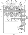
- FIG. 1 is a sectional view of a drive mechanism-integrated electric power generating apparatus 1 including a toroidal continuously variable transmission 10 according to the embodiment.
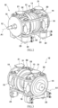
- FIG. 2 is a perspective view showing the toroidal continuously variable transmission 10 of FIG. 1 .
- FIG. 3 is a perspective view showing the toroidal continuously variable transmission 10 of FIG. 1 from a different point of view.
- FIG. 4 is a sectional view showing the toroidal continuously variable transmission 10 of FIG. 2 .
- FIG. 4 is a sectional view of a phase around an axis A1 where power rollers 18 and trunnions 19 do not exist, i.e., a sectional view of the phase that is different from a phase of FIG. 1 by 90°.
- FIGS. 2 and 3 only one first containment body 50 corresponding to one input disc 13 is shown, and the other first containment body 50 corresponding to the other the input disc 13 and second containment bodies 60 corresponding to output discs 14 and 15 are not shown.
- the drive mechanism-integrated electric power generating apparatus 1 (Integrated Drive Generator) is used for an AC power supply of an aircraft and includes a housing 2 attached to an engine of the aircraft.
- the housing 2 houses an input mechanism 3, the toroidal continuously variable transmission 10 (hereinafter referred to as a "transmission"), a power transmission mechanism 4, and a power generator 5.
- the housing 2 is made of, for example, a metal material but may be made of fiber-reinforced resin.
- the transmission 10 does not have to be a part of the drive mechanism-integrated electric power generating apparatus and may be used for applications other than aircrafts.
- the transmission 10 includes a transmission input shaft 11 and a transmission output shaft 12 (rotating shaft) which are coaxially located and relatively rotatable.
- the transmission input shaft 11 is connected to an engine rotating shaft through the input mechanism 3.
- the input mechanism 3 includes a device input shaft 3a and a gear 3b. Rotational power from the engine rotating shaft is input to the device input shaft 3a, and the gear 3b rotates integrally with the device input shaft 3a.
- An input gear 6 that rotates integrally with the transmission input shaft 11 is located at the transmission input shaft 11.
- the transmission output shaft 12 is connected to a power generator input shaft 5a of the power generator 5 through the power transmission mechanism 4 (for example, a gear train).
- the rotational power taken out from the engine rotating shaft is input to the transmission input shaft 11 through the input mechanism 3, and the rotational power of the transmission input shaft 11 is transmitted to the input discs 13.
- the transmission 10 changes the speed of the rotation of the transmission input shaft 11 and outputs the rotation to the transmission output shaft 12.
- the rotational power of the transmission output shaft 12 is transmitted to the power generator input shaft 5a through the power transmission mechanism 4.
- the power generator input shaft 5a When the power generator input shaft 5a is rotated, the power generator 5 generates AC power.
- a change gear ratio of the transmission 10 is continuously changed such that the rotational speed of the power generator input shaft 5a is maintained at an appropriate value (for example, a value corresponding to a frequency appropriate for the operation of an electric component of the aircraft).
- the transmission 10 is of, for example, a half toroidal type and a double cavity type and includes the input discs 13 and the output discs 14 and 15 which form two pairs.
- the input discs 13 are fitted to the transmission input shaft 11 so as to rotate integrally with the transmission input shaft 11.
- the output discs 14 and 15 are fitted to the transmission output shaft 12 so as to rotate integrally with the transmission output shaft 12.
- the discs 13 to 15 that form two pairs are located adjacent to each other in a direction along the axis A1 so as to rotate about the axis A1.
- the input discs 13 and the output discs 14 and 15 are located so as to be opposed to each other in the direction along the axis A1 of the transmission 10.
- the input discs 13 include respective concave speed change surfaces 31a opposed to each other.
- the output discs 14 and 15 include respective concave speed change surfaces 41a opposed to each other.
- the input discs 13 and the output discs 14 and 15 form annular cavities around the axis A1 by the speed change surfaces 31a and 41a.
- the type of the transmission is not limited to the double cavity type and may be a single cavity type.
- the transmission 10 is of, for example, a middle input type.
- the transmission output shaft 12 is inserted into the transmission input shaft 11 and projects from the transmission input shaft 11 toward both sides.
- a pair of input discs 13 are middle discs located back to back on the transmission input shaft 11.
- the input gear 3b that rotates integrally with the transmission input shaft 11 is located between the pair of input discs 13.
- a pair of output discs 14 and 15 are outside discs located outside the pair of input discs 13 in the direction along the axis A1.
- the output discs 14 and 15 are connected to the power transmission mechanism 4 so as to transmit the rotational power to the power transmission mechanism 4 through a press 17.
- the output disc 14 is prevented from being displaced outward along the axis A1 by a convex portion 12a, projecting in a radial direction, of the transmission output shaft 12.
- the output disc 15 is biased by a preload spring 16 toward the input disc 13.
- the output disc 15 is biased by the press 17 toward the input disc 13.
- the press 17 moves the output discs 14 and 15 in the direction along the axis A1 between a closest position where the input discs 13 and the output discs 14 and 15 are located closest to each other in the direction along the axis A1 and a farthest position where the input discs 13 and the output discs 14 and 15 are located farthest from each other in the direction along the axis A1.
- the closest position may be referred to as a first position
- the farthest position may be referred to as a second position.
- the press 17 is, for example, a loading cam.
- the press 17 includes a cam plate 17a and a cam roller 17b.
- the cam plate 17a is biased by the preload spring 16 toward the output disc 15.
- the cam roller 17b is located between the output disc 15 and the cam plate 17a.
- a surface (back surface) of the output disc 15 on which the cam roller 17b slides and a surface of the cam plate 17a on which the cam roller 17b slides are, for example, non-planar cam surfaces.
- the transmission 10 includes: the power rollers 18 located in the cavities; and the trunnions 19 which support the power rollers 18 such that the power rollers 18 are tiltable.
- the trunnions 19 are supported by the housing 2 so as to be tiltable about an axis A2 and displaceable in a direction along the axis A2.
- the axis A2 and the axis A1 are skew lines.
- the power roller 18 is supported by the trunnion 19 so as to be rotatable about an axis A3 perpendicular to the the axis A2.
- the power roller 18 is located in a predetermined phase region around the axis A1.
- Two power rollers 18 are located at a pair of discs that are the input disc and the output disc (i.e., a pair of discs that are the input disc 13 and the output disc 14 or a pair of discs that are the input disc 13 and the output disc 15).
- the trunnion 19 is connected to a linear-motion actuator 22, and the actuator 22 makes the trunnion 19 reciprocate in the direction along the axis A2 together with the power roller 18.
- the actuator 22 is, for example, a hydraulic actuator (hydraulic cylinder).
- the power roller 18 is located between the speed change surface 31a of the input disc 13 and the speed change surface 41a of the output disc 14 or 15 so as to be tiltable about the axis A2.
- the power roller 18 changes the speed of the rotational power of the input disc 13 at the change gear ratio corresponding to the tilt angle and then transmits the rotational power to the output disc 14 or 15.
- the output disc 15 is pushed by the press 17 so as to approach the input disc 13, and this increases pressure by which the input disc 13 and the output disc 14 sandwich the power roller 18 and pressure by which the input disc 13 and the output disc 15 sandwich the power roller 18.
- one end portion of the trunnion 19 is supported by a trunnion yoke 20 so as to be rotatable.
- the trunnion yoke 20 has, for example, a square frame shape.
- the trunnion yoke 20 is connected to the housing 2 by a yoke support 21.
- the other end portion of the trunnion 19 is connected to the actuator 22.
- the actuator 22 displaces the trunnion 19 in the direction along the tilting axis A2.
- the actuator 22 is supported by an actuator body 23.
- the actuator body 23 is fixed to the housing 2 by a fixture (for example, a bolt).
- the input disc 13 includes a disc main body portion 31 and a cylindrical portion 32.
- the disc main body portion 31 includes the speed change surface 31a opposed to the power roller 18.
- the cylindrical portion 32 projects from the disc main body portion 31 toward an opposite side of the power roller 18 along the axis A1.
- the disc main body portion 31 has a circular-arc section.
- the cylindrical portion 32 of the input disc 13 is supported by a bearing 24 so as to be rotatable, and the bearing 24 is supported by a bearing support 25 so as to be rotatable.
- the bearing support 25 is located behind the discs 13 to 15 and is fixed to the housing 2 by a fixture B (for example, a bolt).
- the bearing support 25 includes an opening through which part of the input gear 6 is exposed such that the input gear 6 meshes with the gear 3b.
- the bearing support 25 includes an annular portion 25a and an arm portion 25b.
- the annular portion 25a is externally fitted to a pair of bearings 24 that are externally fitted to the cylindrical portions 32 of the pair of input discs 13.
- the arm portion 25b projects outward in the radial direction from the annular portion 25a.
- the arm portion 25b is fixed to the housing 2 by the fixture B.
- the annular portion 25a is shown as one piece but may be a combination of plural parts.
- the transmission 10 includes a pair of first containment bodies 50 and a pair of second containment bodies 60.
- the first containment bodies 50 cover the pair of input discs 13, and the second containment bodies 60 cover the pair of output discs 14 and 15. Even if the discs 13 to 15 break during the operation of the transmission 10, the containment bodies 50 and 60 can prevent disc fragments, on which centrifugal force acts, from directly colliding with the housing.
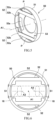
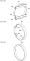
- FIG. 5 is a perspective view showing the first containment body 50 of FIG. 4 .
- FIG. 6 is a front view showing the first containment body 50 of FIG. 5 . Since a basic structure of the first containment body 50 and a basic structure of the second containment body 60 are the same as each other, the basic structure of the first containment body 50 will be mainly described below.
- the first containment body 50 (second containment body 60) includes a ring 51 (ring 61) and may further include a guard 52 (guard 62) and a ring support 53 (ring support 63).
- the first containment body 50 is made of metal but may be made of resin (for example, fiber-reinforced resin), another material, or a combination thereof.
- the ring 51 has a cylindrical shape including the axis A1 that coincides with a rotation axis of the input disc 13.
- the ring 51 covers an outer peripheral surface 31b of the input disc 13 so as to be spaced apart from the outer peripheral surface 31b in the radial direction.
- the dimension of a gap between an inner peripheral surface of the ring 51 and the outer peripheral surface 31b of the input disc 13 is, for example, 1 to 5 mm, preferably 1.2 to 3 mm, more preferably 1.3 to 2 mm.
- the guard 52 is located at one side (side close to the power roller 18) of the ring 51 in the direction along the axis A1 and is integrally connected to the ring 51.
- the guard 52 may be separably connected to the ring 51.
- the guard 52 projects from the ring 51 toward a radially inner side.
- the guard 52 has, for example, a plate shape whose thickness direction is along the axis A1.
- the guard 52 includes, for example, a band plate portion 52a and projecting plate portions 52b but may include only the band plate portion 52a.
- the band plate portion 52a has a band plate shape extending in one direction and connects two different points on an outer circumference of the ring 51.
- An opening P is located between the band plate portion 52a and the ring 51.
- the opening P does not have to be located between the band plate portion 52a and the ring 51.
- the projecting plate portion 52b is a projection that projects from the ring 51 inward in the radial direction.
- a projection amount of the projecting plate portion 52b in the radial direction is, for example, a value within a range of 10% to 30% of a radius of the inner peripheral surface of the ring 51.
- the guard 52 may include only the band plate portion 52a or only the projecting plate portion 52b.
- the ring supports 53 are located behind the respective discs 13 to 15.
- the ring support 53 is located between the ring 51 and the bearing support 25 (bearing 24) in the axial direction and connects the ring 51 and the bearing support 25 (bearing 24).
- the ring support 53 can be connected to one of the bearing support 25 and the bearing 24 or can be connected to both of the bearing support 25 and the bearing 24.
- the ring support 53 is separably connected to the ring 51 but may be integrally connected to the ring 51.
- the ring support 53 is, for example, an annular plate.
- the ring support 53 may include an oil-drain port 53a. In this case, the oil-drain port 53a can be partially located at the ring support 53 in a circumferential direction around the axis A1.
- Various methods may be adopted as means for fixing the ring support 53 to the ring 51.
- a fixing method using press fitting for example, a retainer
- a fixing method using a fixture for example, a bolt
- the ring support 53 may be positioned and fixed to the ring 51 by a retainer 54 (see FIG. 4 ) while being internally fitted to the ring 51.
- the retainer 54 is, for example, an annular body.
- the power rollers 18 are located in a predetermined phase region around the axis A1 of the ring 51.
- the ring 51 includes: a first section S1 corresponding to the above phase region of the power rollers 18; and a second section S2 that is a region other than the above region.
- a region of the ring 51 on which the power rollers 18 are projected in a direction along the axis A3 may be the first section S1, and a region other than the above region may be the second section S2.
- the guard 52 is located in the second section S2 of the ring 51 but is not located in the first section S1 of the ring 51.
- the guard 52 is located in the second section S2.
- the guard 52 may be located in not only the second section S2 but also the first section S1 as long as the guard 52 does not limit the operations of the power rollers 18.
- the guard 52 is opposed to the speed change surface 31a of the input disc 13 so as to be spaced apart from the speed change surface 31a.
- the guard 62 is opposed to the speed change surface 41a of the output disc 14 so as to be spaced apart from the speed change surface 41a.
- the ring support 53 is opposed to the back surface of the input disc 13 so as to be spaced apart from the back surface of the input disc 13.
- the ring support 63 is opposed to the back surface of the output disc 14 or 15 so as to be spaced apart from the back surface of the output disc 14 or 15.
- Each of the ring supports 53 and 63 is connected to the housing 2 through a below-described supporting body.
- a minimum value of a gap between the guard 52 and the speed change surface 31a of the input disc 13 is, for example, 0.5 to 5 mm.
- a maximum value of the gap between the guard 52 and the speed change surface 31a of the input disc 13 is, for example, 1 to 8 mm.
- a minimum value of a gap between the guard 62 and the speed change surface 41a of the output disc 14 is, for example, 0.5 to 8 mm.
- a maximum value of the gap between the guard 62 and the speed change surface 41a of the output disc 14 is, for example, 1 to 11 mm.
- a maximum dimension of the ring 51 of the first containment body 50 in the direction along the axis A1 is larger than a maximum dimension of the outer peripheral surface 31b of the input disc 13 in the direction along the axis A1.
- a maximum dimension of the ring 61 of the second containment body 60 in the direction along the axis A1 is larger than a maximum dimension of an outer peripheral surface 41b of the output disc 14 or 15 in the direction along the axis A1.
- Each of the dimension of the outer peripheral surface 31b of the input disc 13 in the direction along the axis A1 and the dimensions of the outer peripheral surfaces 41b of the output discs 14 and 15 in the direction along the axis A1 is constant around the axis A1.
- the first containment body 50 is supported by the supporting body connected to the housing 2.
- the first containment body 50 is connected to the housing 2 through the supporting body having a function (for example, a function of supporting the bearing 24) different from the function of supporting the first containment body 50.
- the supporting body may be, for example, the bearing support 25 connected to the housing 2, the below-described actuator body 23, or the like.
- the bearing support 25 is lined up with respect to the input disc 13 in the direction along the axis A1.
- the bearing 24, the ring support 53, and the ring 51 are connected to the bearing support 25.
- the first containment body 50 is not directly connected to the housing 2 but is indirectly connected to the housing 2 through the supporting body (bearing support 25).
- the second containment body 60 may be indirectly connected to the housing 2 through the supporting body connected to the housing 2.
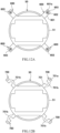
- FIG. 7A is a sectional view showing a relation between the second section S2 of the ring 51 of the first containment body 50 of FIG. 2 and the input disc 13.
- FIG. 7B is a sectional view showing a relation between the first section S1 of the ring 51 of the first containment body 50 of FIG. 2 and the input disc 13.
- the first containment body 50 is fixedly located, and the input disc 13 rotates about the axis A1 but is not displaced in the direction along the axis A1.
- the first containment body 50 and the input disc 13 are not displaced relative to each other in the direction along the axis A1.
- an end of the second section S2 of the ring 51 which is close to the power roller 18 in the direction along the axis A1 projects closer to the power roller 18 than an end of the outer peripheral surface 31b of the input disc 13 which is close to the power roller 18 in the direction along the axis A1.
- the end of the second section S2 of the ring 51 which is close to the power roller 18 in the direction along the axis A1 may be the same in position in the direction along the axis A1 as the end of the outer peripheral surface 31b of the input disc 13 which is close to the power roller 18 in the direction along the axis A1.
- an end of the first section S1 of the ring 51 which is close to the power roller 18 in the direction along the axis A1 is the same in position in the direction along the axis A1 as the end of the outer peripheral surface 31b of the input disc 13 which is close to the power roller 18 in the direction along the axis A1.
- the end of the first section S1 of the ring 51 which is close to the power roller 18 in the direction along the axis A1 may project closer to the power roller 18 than the end of the outer peripheral surface 31b of the input disc 13 which is close to the power roller 18 in the direction along the axis A1.
- that the above ends are the same in position as each other includes a case where the above ends are substantially the same in position as each other.
- the second section S2 of the ring 51 may or may not project beyond the first section S1 of the ring 51 in the direction along the axis A1 from the input disc 13 toward the power roller 18.
- a maximum dimension of the second section S2 of the ring 51 in the direction along the axis A1 may be larger than or equal to a maximum dimension of the first section S1 of the ring 51 in the direction along the axis A1.
- the ring 51 may be located in a range including a gravity center position G of the input disc 13 in the direction along the axis A1. In this case, a virtual line V1 extending in the radial direction (direction orthogonal to the axis A1) through the gravity center position G of the input disc 13 intersects with the ring 51.
- FIG. 8A is a sectional view showing a relation between the second section S2 of the ring 61 of the second containment body 60 of FIG. 2 and the output disc 14.
- FIG. 8B is a sectional view showing a relation between the first section S1 of the ring 61 of the second containment body 60 of FIG. 2 and the output disc 14.
- the second containment body 60 is fixedly located, but the output disc 14 is displaceable in the direction along the axis A1 by pressing force of the press 17 (see FIG. 4 ).
- the output disc 14 may move in the direction along the axis A1 between the closest position where the output disc 14 is located closest to the input disc 13 in the direction along the axis A1 and the farthest position where the output disc 14 is located farthest from the input disc 13 in the direction along the axis A1.
- the second containment body 60 and the output disc 14 are displaced relative to each other in the direction along the axis A1.
- the output disc 14 at the closest position is shown by a solid line
- the output disc 14 at the farthest position is shown by a broken line
- the output disc 14 at the farthest position is shown by a solid line
- the output disc 14 at the closest position is shown by a broken line. Since the output disc 14 and the output disc 15 are similar to each other, the following will mainly describe the output disc 14.
- an end of the second section S2 of the ring 61 of the second containment body 60 which is close to the power roller 18 in the direction along the axis A1 may project closer to the power roller 18 than an end of the outer peripheral surface 41b of the output disc 14 which is close to the power roller 18 in the direction along the axis A1.
- the end of the second section S2 of the ring 61 which is close to the power roller 18 in the direction along the axis A1 may be the same in position in the direction along the axis A1 as the end of the outer peripheral surface 41b of the output disc 14 which is close to the power roller 18 in the direction along the axis A1.
- an end of the first section S1 of the ring 61 which is close to the power roller 18 in the direction along the axis A1 is the same in position in the direction along the axis A1 as an end of the outer peripheral surface 41b of the output disc 14 which is close to the power roller 18 in the direction along the axis A1.
- the second section S2 of the ring 61 projects beyond the first section S1 of the ring 61 in the direction along the axis A1 from the output disc 14 toward the power roller 18.
- the ring 61 may be located in a range including the gravity center position G of the output disc 14 in the direction along the axis A1.
- a virtual line V2 extending in the radial direction (direction orthogonal to the axis A1) through the gravity center position G of the output disc 14 intersects with the ring 61.
- the dimensions of the first sections S1 of the rings 51 and 61 in the direction along the axis A1 and the dimensions of the second sections S2 of the rings 51 and 61 in the direction along the axis A1 are larger than the dimensions of the outer peripheral surfaces 31b and 41b of the corresponding discs 13 and 14 in the direction along the axis A1.
- the disc fragments B1 to B4 which try to fly out in not only a direction perpendicular to the direction along the axis A1 but also a direction oblique to the direction along the axis A1 can be prevented from directly colliding with the housing 2 by the guard 52 of the first containment body 50. Therefore, the containment performance of the housing 2 can be compensated without increasing the thickness of the housing 2 and changing the design of the housing 2.
- the gap between the input disc 13 (or the output disc 14 or 15) and the ring 51 can be set to be small. Therefore, when the disc fragments B1 to B4 on which the centrifugal force acts collide with the ring 51, the acceleration of the disc fragments B1 to B4 in the radial direction can be made low, and collision angles of the disc fragments B1 to B4 to the ring 51 can be made small. With this, an impact load generated at the ring 51 can be made low.
- the disc fragments B1 to B4 can be prevented from directly colliding with the housing 2 by the ring 51 and the guard 52 (see FIG. 1 ).
- the maximum dimension of the ring 51 in the direction along the axis A1 is larger than the maximum dimension of the outer peripheral surface 31b of the disc 13 in the direction along the axis A1 (see FIG. 4 ). Therefore, even when the disc fragments B1 to B4 are displaced in the direction along the axis A1 and try to fly out in not only the direction perpendicular to the direction along the axis A1 but also the direction oblique to the direction along the axis A1, the disc fragments B1 to B4 can be prevented from directly colliding with the housing 2 by the ring 51. Regarding this principle of the containment, the same is true for the second containment body 60.
- the ring 51 may be located in a range including the gravity center position G of the input disc 13 in the direction along the axis A1
- the ring 61 may be located in a range including the gravity center position G of the output disc 14 or 15 in the direction along the axis A1.
- the disc fragments B1 to B4 on which the centrifugal force acts can be prevented from directly colliding with the housing 2 by the rings 51 and 61.
- the second section S2 of the ring 51 may project beyond the first section S1 of the ring 51 in the direction along the axis A1 from the disc 13 toward the power roller 18, and the second section S2 of the ring 61 may project beyond the first section S1 of the ring 61 in the direction along the axis A1 from the disc 14 or 15 toward the power roller 18.
- the disc fragments B1 to B4 can be prevented from directly colliding with the housing 2 by the rings 51 and 61 while preventing the rings 51 and 61 from limiting tilting ranges of the power rollers 18 (and the trunnions 19).
- the containment body 50 is connected to the bearing support 25 connected to the housing 2. Therefore, another part (bearing support 25) is interposed between the containment body 50 and the housing 2. With this, the impact load transmitted from the containment body 50 to the housing 2 is reduced, and the containment performance of the housing 2 can be compensated.
- a component, having another function for example, the bearing support 25 is originally a part that supports the bearing 24), of the toroidal continuously variable transmission is used as the part interposed between the containment body 50 and the housing 2. Therefore, the number of parts can be prevented from increasing.
- the containment body 50 includes the guard 52
- the containment body 60 includes the guard 62
- the disc fragments B1 to B4 can be prevented from flying out by the guards 52 and 62.
- the guard 52 is integrated with the ring 51
- the guard 62 is integrated with the ring 61
- the rigidity of the rings 51 and 61 can be increased without increasing the number of parts of the rings 51 and 61.
- the rigidity of the rings 51 and 61 can be increased without increasing the number of parts of the rings 51 and 61.
- Each of the ring supports 53 and 63 may include the oil-drain port 53a that is open outward in the radial direction.
- the oil having entered into a space surrounded by the ring 51 and the ring support 53 can be discharged through the oil-drain port 53a outward in the radial direction before being stirred by the disc 13, and the oil having entered into a space surrounded by the ring 61 and the ring support 63 can be discharged through the oil-drain port 53a outward in the radial direction before being stirred by the disc 14 or 15.
- FIG. 10A is a perspective view of a first modified example of the guard of the containment body.
- a guard 152 of the first modified example is separable from a ring 151.
- the guard 152 is detachably fixed to the ring 151 by fixtures 155 (for example, bolts). With this, the guard 152 can be detached from the ring 151 when assembling the ring 151 to the transmission 10, and this improves the ease of work of the assembling.
- FIG. 10B is a perspective view of a second modified example of the guard of the containment body.
- a guard 252 of the second modified example is a projection projecting inward in the radial direction from a ring 251.
- a projection amount of the guard 252 in the radial direction is, for example, a value within a range of 10% to 30% of a radius of an inner peripheral surface of the ring 251.
- FIG. 10C is a perspective view of a third modified example of the containment body.
- a guard may not be located at a ring 251A in the containment body. According to FIG. 10C , the containment performance of the housing 2 can be compensated without increasing the number of parts of the containment body.
- FIG. 11A is a perspective view of a first modified example of a connection structure between the ring and the ring support in the containment body.
- a ring support 353 is detachably fixed to a ring 351 by fixtures 355 (for example, bolts). With this, the ring support 353 can be detached from the ring 351 when assembling the ring 351 to the transmission 10, and this improves the ease of work of the assembling.
- FIG. 11B is a perspective view of a second modified example of the connection structure between the ring and the ring support in the containment body.
- a ring support 453 and a ring 451 are formed as one piece.
- the ring support 453 and the bearing support 25 may be separable from each other.
- FIG. 11C is a perspective view of a third modified example of the connection structure between the ring and the ring support in the containment body.
- an end of a ring 551 in the direction along the axis A1 includes cutouts 551a that are lined up in the circumferential direction so as to be spaced apart from each other.
- An outer peripheral end of a ring support 553 includes projections 553a that are lined up in the circumferential direction so as to be spaced apart from each other.
- a dimension of the cutout 551a is larger in the direction along the axis A1 than a dimension of the projection 553a.
- the ring support 553 is locked to the ring 551 by fitting the projections 553a to the cutouts 551a. Then, by attaching a retainer 554 to the ring 551, the ring support 553 is connected to the ring 551 by the retainer 554.
- the retainer 554 is annular, and an outer peripheral end of the retainer 554 includes projections 554a that are lined up in the circumferential direction so as to be spaced apart from each other.
- the projections 554a of the retainer 554 are fitted to the cutouts 551a of the ring 551 so as to press the projections 553a of the ring support 553 in the direction along the axis A1.
- FIG. 11D is a perspective view of a fourth modified example of the connection structure between the ring and the ring support in the containment body.
- a ring support 653 and a retainer 654 are inserted into and fitted to a ring 651 from a side where the power roller 18 is located (see FIG. 4 ).
- the ring support 653 may be fixed to an adjacent member (for example, the bearing support 25) by a fixture (for example, a bolt) or by press fitting using the retainer 654.
- FIG. 12A is a front view of a first modified example of a support structure of the containment body.
- the support structure of the first modified example includes a joint 600 that connects the containment body 50 to the housing 2 (see FIG. 1 ).
- the joint 600 includes a bracket 601 and a fixture 602 (for example, a bolt).
- the bracket 601 projects from the ring 51 of the containment body 50, and the fixture 602 fixes the bracket 601 to the housing 2.
- the bracket 601 includes a fixing hole 601a into which the fixture 602 is inserted.
- the fixing hole 601a is a hole that is adequately larger in diameter than a portion of the fixture 602 which is located in the fixing hole 601a.
- an inner diameter of the fixing hole 601a is 1.3 to 2.0 times larger than an outer diameter of the portion of the fixture 602 which is located in the fixing hole 601a.
- the bracket 601 When impact is generated at the containment body 50, the impact is transmitted to the bracket 601, and therefore, the bracket 601 may be displaced relative to the fixture 602 within a range of the fixing hole 601a.
- the fixing hole 601a of the bracket 601 serves as an absorber 603 that allows the containment body 50 to be displaced by the impact. With this, the impact load transmitted from the containment body 50 to the housing 2 is reduced, and the containment performance of the housing 2 can be compensated.
- FIG. 12B is a front view of a second modified example of the support structure of the containment body.
- the support structure of the second modified example includes a joint 700 that connects the containment body 50 to the housing 2.
- the joint 700 includes a bracket 701 and a fixture 702 (for example, a bolt).
- the bracket 701 projects from the ring 51 of the containment body 50.
- the fixture 702 fixes the bracket 701 to the housing 2.
- the bracket 701 includes a fixing hole 701a and an absorber 701b.
- the fixture 702 is inserted into the fixing hole 701a.
- the absorber 701b has a detour shape that curves in a direction different from an extending direction (main direction of the bracket 701) of a straight line connecting a portion of the bracket 701 which is connected to the housing 2 and a portion of the bracket 701 which is connected to the containment body 50.
- the absorber 701b allows the bracket 701 to elastically extend or contract in the main direction.
- the absorber 701b has an inverted U shape projecting in a direction orthogonal to the main direction of the bracket 701.
- the absorber 701b may elastically deform.
- the second modified example of the support structure of the containment body may be combined with the first modified example of the support structure of the containment body.
- the joints 600 may be used as two support portions, and the joints 700 may be used as the remaining two support portions.
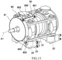
- FIG. 13 is a perspective view of a third modified example of the support structure of the containment body.
- the first containment body 50 and the second containment body 60 are connected to each other by a coupling body 800.
- the coupling body 800 has, for example, a bar shape.
- One end portion of the coupling body 800 is detachably fixed to the first containment body 50 (for example, the ring 51) by a fixture 801 (for example, a bolt).
- the other end portion of the coupling body 800 is detachably fixed to the second containment body 60 by a fixture 802 (for example, a bolt).
- the coupling body 800 can support the first containment body 50 and the second containment body 60.
- FIG. 13 shows only one coupling body 800. However, it is preferable that the first containment body 50 and the second containment body 60 be connected to each other by the coupling bodies 800.
- a bracket 803 is integrally connected to the second containment body 60 (for example, the ring 61). Moreover, the bracket 803 may be separably connected to the second containment body 60.
- the bracket 803 is fixed to the actuator body 23 by a fixture 804 (for example, a bolt).
- the second containment body 60 is connected to the actuator 22 and the housing 2 through the bracket 803 and the actuator body 23 (supporting body).
Landscapes
- Engineering & Computer Science (AREA)
- General Engineering & Computer Science (AREA)
- Mechanical Engineering (AREA)
- Aviation & Aerospace Engineering (AREA)
- Friction Gearing (AREA)
Abstract
Description
- The present disclosure relates to a toroidal continuously variable transmission.
- A toroidal continuously variable transmission that performs speed change by tilting a power roller located between an input disc and an output disc has been known (see
PTL 1, for example). - PTL 1:
Japanese Laid-Open Patent Application Publication No. 2001-158400 - If the disc breaks during the operation of the toroidal continuously variable transmission, fragments of the disc collide with a housing by centrifugal force. However, if the thickness of the housing is increased or the design of the housing is changed in order to satisfy containment performance necessary to contain respective parts in the housing, the weight and manufacturing cost of the housing increase.
- An object of the present disclosure is to compensate containment performance of a housing without increasing the thickness of the housing and changing the design of the housing.
- A toroidal continuously variable transmission according to one aspect of the present disclosure includes: an input disc including a speed change surface; an output disc including a speed change surface; a power roller located between the speed change surface of the input disc and the speed change surface of the output disc so as to be tiltable; at least one containment body covering a target disc that is at least one of the input disc and the output disc; and a housing that houses the input disc, the output disc, the power roller, and the containment body. The containment body includes a ring that covers an outer peripheral surface of the target disc so as to be spaced apart from the outer peripheral surface of the target disc in a radial direction. A maximum dimension of the ring in an axial direction is larger than a maximum dimension of the outer peripheral surface of the target disc in the axial direction.
- According to the above configuration, when the disc breaks during the operation of the toroidal continuously variable transmission, and disc fragments on which centrifugal force acts try to fly out in a direction perpendicular to the axial direction, the disc fragments are prevented from directly colliding with the housing by the ring of the containment body. Then, the maximum dimension of the ring in the axial direction is larger than the maximum dimension of the outer peripheral surface of the disc in the axial direction. Therefore, not only when the disc fragments try to fly out in a direction perpendicular to the axial direction but also when the disc fragments try to fly out in a direction oblique to the axial direction, the disc fragments can be prevented from directly colliding with the housing by the ring within a range of the maximum dimension of the ring in the axial direction. On this account, the containment performance of the housing can be compensated.
- According to one aspect of the present disclosure, containment performance of a housing can be compensated without increasing the thickness of the housing and changing the design of the housing.
-
-
FIG. 1 is a sectional view showing a drive mechanism-integrated electric power generating apparatus including a toroidal continuously variable transmission according to an embodiment. -
FIG. 2 is a perspective view showing the toroidal continuously variable transmission ofFIG. 1 . -
FIG. 3 is a perspective view showing the toroidal continuously variable transmission ofFIG. 1 from a different point of view. -
FIG. 4 is a sectional view showing the toroidal continuously variable transmission ofFIG. 2 . -
FIG. 5 is a perspective view showing a containment body ofFIG. 4 . -
FIG. 6 is a front view showing the containment body ofFIG. 5 . -
FIG. 7A is a sectional view showing a relation between an input disc and a second section of a ring of a first containment body ofFIG. 2 .FIG. 7B is a sectional view showing a relation between the input disc and a first section of the ring of the first containment body ofFIG. 2 . -
FIG. 8A is a sectional view showing a relation between an output disc and a second section of a ring of a second containment body ofFIG. 2 .FIG. 8B is a sectional view showing a relation between the output disc and a first section of the ring of the second containment body ofFIG. 2 . -
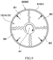
FIG. 9 is a schematic diagram for explaining a containment function of the containment body ofFIG. 5 when the disc breaks. -
FIG. 10A is a perspective view of a first modified example of a guard of the containment body.FIG. 10B is a perspective view of a second modified example of the guard of the containment body.FIG. 10C is a perspective view of a third modified example of the containment body. -
FIG. 11A is a perspective view of a first modified example of a connection structure between the ring and a ring support in the containment body.FIG. 11B is a perspective view of a second modified example of the connection structure between the ring and the ring support in the containment body.FIG. 11C is a perspective view of a third modified example of the connection structure between the ring and the ring support in the containment body.FIG. 11D is a perspective view of a fourth modified example of the connection structure between the ring and the ring support in the containment body. -
FIG. 12A is a front view of a first modified example of a support structure of the containment body.FIG. 12B is a front view of a second modified example of the support structure of the containment body. -
FIG. 13 is a perspective view of a third modified example of the support structure of the containment body. - Hereinafter, an embodiment will be described with reference to the drawings.
-
FIG. 1 is a sectional view of a drive mechanism-integrated electricpower generating apparatus 1 including a toroidal continuouslyvariable transmission 10 according to the embodiment.FIG. 2 is a perspective view showing the toroidal continuouslyvariable transmission 10 ofFIG. 1 .FIG. 3 is a perspective view showing the toroidal continuouslyvariable transmission 10 ofFIG. 1 from a different point of view.FIG. 4 is a sectional view showing the toroidal continuouslyvariable transmission 10 ofFIG. 2 .FIG. 4 is a sectional view of a phase around an axis A1 wherepower rollers 18 andtrunnions 19 do not exist, i.e., a sectional view of the phase that is different from a phase ofFIG. 1 by 90°. Moreover, inFIGS. 2 and 3 , only onefirst containment body 50 corresponding to oneinput disc 13 is shown, and the otherfirst containment body 50 corresponding to the other theinput disc 13 andsecond containment bodies 60 corresponding tooutput discs - As shown in
FIG. 1 , the drive mechanism-integrated electric power generating apparatus 1 (Integrated Drive Generator) is used for an AC power supply of an aircraft and includes ahousing 2 attached to an engine of the aircraft. Thehousing 2 houses aninput mechanism 3, the toroidal continuously variable transmission 10 (hereinafter referred to as a "transmission"), apower transmission mechanism 4, and apower generator 5. Thehousing 2 is made of, for example, a metal material but may be made of fiber-reinforced resin. Thetransmission 10 does not have to be a part of the drive mechanism-integrated electric power generating apparatus and may be used for applications other than aircrafts. - The
transmission 10 includes atransmission input shaft 11 and a transmission output shaft 12 (rotating shaft) which are coaxially located and relatively rotatable. Thetransmission input shaft 11 is connected to an engine rotating shaft through theinput mechanism 3. Theinput mechanism 3 includes a device input shaft 3a and agear 3b. Rotational power from the engine rotating shaft is input to the device input shaft 3a, and thegear 3b rotates integrally with the device input shaft 3a. Aninput gear 6 that rotates integrally with thetransmission input shaft 11 is located at thetransmission input shaft 11. Thetransmission output shaft 12 is connected to a powergenerator input shaft 5a of thepower generator 5 through the power transmission mechanism 4 (for example, a gear train). - The rotational power taken out from the engine rotating shaft is input to the
transmission input shaft 11 through theinput mechanism 3, and the rotational power of thetransmission input shaft 11 is transmitted to theinput discs 13. Thetransmission 10 changes the speed of the rotation of thetransmission input shaft 11 and outputs the rotation to thetransmission output shaft 12. The rotational power of thetransmission output shaft 12 is transmitted to the powergenerator input shaft 5a through thepower transmission mechanism 4. When the powergenerator input shaft 5a is rotated, thepower generator 5 generates AC power. Regardless of a change in a rotational speed of the engine rotating shaft, a change gear ratio of thetransmission 10 is continuously changed such that the rotational speed of the powergenerator input shaft 5a is maintained at an appropriate value (for example, a value corresponding to a frequency appropriate for the operation of an electric component of the aircraft). - As shown in
FIGS. 1 to 4 , thetransmission 10 is of, for example, a half toroidal type and a double cavity type and includes theinput discs 13 and theoutput discs input discs 13 are fitted to thetransmission input shaft 11 so as to rotate integrally with thetransmission input shaft 11. Theoutput discs transmission output shaft 12 so as to rotate integrally with thetransmission output shaft 12. Thediscs 13 to 15 that form two pairs are located adjacent to each other in a direction along the axis A1 so as to rotate about the axis A1. Theinput discs 13 and theoutput discs transmission 10. - The
input discs 13 include respective concavespeed change surfaces 31a opposed to each other. Theoutput discs speed change surfaces 41a opposed to each other. Theinput discs 13 and theoutput discs - The
transmission 10 is of, for example, a middle input type. Thetransmission output shaft 12 is inserted into thetransmission input shaft 11 and projects from thetransmission input shaft 11 toward both sides. A pair ofinput discs 13 are middle discs located back to back on thetransmission input shaft 11. Theinput gear 3b that rotates integrally with thetransmission input shaft 11 is located between the pair ofinput discs 13. A pair ofoutput discs input discs 13 in the direction along the axis A1. Theoutput discs power transmission mechanism 4 so as to transmit the rotational power to thepower transmission mechanism 4 through apress 17. - The
output disc 14 is prevented from being displaced outward along the axis A1 by aconvex portion 12a, projecting in a radial direction, of thetransmission output shaft 12. Theoutput disc 15 is biased by apreload spring 16 toward theinput disc 13. When thetransmission 10 is rotated, theoutput disc 15 is biased by thepress 17 toward theinput disc 13. Thepress 17 moves theoutput discs input discs 13 and theoutput discs input discs 13 and theoutput discs - The
press 17 is, for example, a loading cam. Thepress 17 includes acam plate 17a and acam roller 17b. Thecam plate 17a is biased by thepreload spring 16 toward theoutput disc 15. Thecam roller 17b is located between theoutput disc 15 and thecam plate 17a. A surface (back surface) of theoutput disc 15 on which thecam roller 17b slides and a surface of thecam plate 17a on which thecam roller 17b slides are, for example, non-planar cam surfaces. - When the
transmission 10 is rotated, force by which theoutput disc 15 and thecam plate 17 separate from each other in the direction along the axis A1 is generated by a cam action of thepress 17. When thecam plate 17a separates from theoutput disc 15, thecam plate 17a pushes one end portion of thetransmission output shaft 12 to displace thetransmission output shaft 12 toward thepower transmission mechanism 4 in the direction along the axis A1. In accordance with this, the other end portion of thetransmission output shaft 12 pushes theoutput disc 14 toward theinput disc 13. To be specific, when thetransmission 10 is rotated, theinput discs 13 are not displaced in the direction along the axis A1, and theoutput discs input discs 13. - The
transmission 10 includes: thepower rollers 18 located in the cavities; and thetrunnions 19 which support thepower rollers 18 such that thepower rollers 18 are tiltable. Thetrunnions 19 are supported by thehousing 2 so as to be tiltable about an axis A2 and displaceable in a direction along the axis A2. The axis A2 and the axis A1 are skew lines. Thepower roller 18 is supported by thetrunnion 19 so as to be rotatable about an axis A3 perpendicular to the the axis A2. - The
power roller 18 is located in a predetermined phase region around the axis A1. Twopower rollers 18 are located at a pair of discs that are the input disc and the output disc (i.e., a pair of discs that are theinput disc 13 and theoutput disc 14 or a pair of discs that are theinput disc 13 and the output disc 15). Thetrunnion 19 is connected to a linear-motion actuator 22, and theactuator 22 makes thetrunnion 19 reciprocate in the direction along the axis A2 together with thepower roller 18. Theactuator 22 is, for example, a hydraulic actuator (hydraulic cylinder). - When the
input discs 13 are rotated, theoutput discs power rollers 18, and thus, thetransmission output shaft 12 is rotated. When thetrunnion 19 and thepower roller 18 are displaced in the direction along the the axis A2, a tilt angle of thepower roller 18 around the axis A2 is changed, and thus, the change gear ratio of thetransmission 10 is continuously changed in accordance with the tilt angle. - The
power roller 18 is located between thespeed change surface 31a of theinput disc 13 and thespeed change surface 41a of theoutput disc power roller 18 changes the speed of the rotational power of theinput disc 13 at the change gear ratio corresponding to the tilt angle and then transmits the rotational power to theoutput disc output disc 14 increases, theoutput disc 15 is pushed by thepress 17 so as to approach theinput disc 13, and this increases pressure by which theinput disc 13 and theoutput disc 14 sandwich thepower roller 18 and pressure by which theinput disc 13 and theoutput disc 15 sandwich thepower roller 18. - As shown in
FIGS. 2 to 4 , one end portion of thetrunnion 19 is supported by atrunnion yoke 20 so as to be rotatable. Thetrunnion yoke 20 has, for example, a square frame shape. Thetrunnion yoke 20 is connected to thehousing 2 by ayoke support 21. The other end portion of thetrunnion 19 is connected to theactuator 22. Theactuator 22 displaces thetrunnion 19 in the direction along the tilting axis A2. Theactuator 22 is supported by anactuator body 23. Theactuator body 23 is fixed to thehousing 2 by a fixture (for example, a bolt). - As shown in
FIG. 4 , theinput disc 13 includes a discmain body portion 31 and acylindrical portion 32. The discmain body portion 31 includes thespeed change surface 31a opposed to thepower roller 18. Thecylindrical portion 32 projects from the discmain body portion 31 toward an opposite side of thepower roller 18 along the axis A1. The discmain body portion 31 has a circular-arc section. Thecylindrical portion 32 of theinput disc 13 is supported by a bearing 24 so as to be rotatable, and thebearing 24 is supported by a bearingsupport 25 so as to be rotatable. The bearingsupport 25 is located behind thediscs 13 to 15 and is fixed to thehousing 2 by a fixture B (for example, a bolt). The bearingsupport 25 includes an opening through which part of theinput gear 6 is exposed such that theinput gear 6 meshes with thegear 3b. - The bearing
support 25 includes anannular portion 25a and anarm portion 25b. Theannular portion 25a is externally fitted to a pair ofbearings 24 that are externally fitted to thecylindrical portions 32 of the pair ofinput discs 13. Thearm portion 25b projects outward in the radial direction from theannular portion 25a. Thearm portion 25b is fixed to thehousing 2 by the fixture B. InFIG. 4 , theannular portion 25a is shown as one piece but may be a combination of plural parts. - The
transmission 10 includes a pair offirst containment bodies 50 and a pair ofsecond containment bodies 60. Thefirst containment bodies 50 cover the pair ofinput discs 13, and thesecond containment bodies 60 cover the pair ofoutput discs discs 13 to 15 break during the operation of thetransmission 10, thecontainment bodies -
FIG. 5 is a perspective view showing thefirst containment body 50 ofFIG. 4 .FIG. 6 is a front view showing thefirst containment body 50 ofFIG. 5 . Since a basic structure of thefirst containment body 50 and a basic structure of thesecond containment body 60 are the same as each other, the basic structure of thefirst containment body 50 will be mainly described below. As shown inFIGS. 4 to 6 , the first containment body 50 (second containment body 60) includes a ring 51 (ring 61) and may further include a guard 52 (guard 62) and a ring support 53 (ring support 63). Thefirst containment body 50 is made of metal but may be made of resin (for example, fiber-reinforced resin), another material, or a combination thereof. - The
ring 51 has a cylindrical shape including the axis A1 that coincides with a rotation axis of theinput disc 13. Thering 51 covers an outerperipheral surface 31b of theinput disc 13 so as to be spaced apart from the outerperipheral surface 31b in the radial direction. The dimension of a gap between an inner peripheral surface of thering 51 and the outerperipheral surface 31b of theinput disc 13 is, for example, 1 to 5 mm, preferably 1.2 to 3 mm, more preferably 1.3 to 2 mm. - The
guard 52 is located at one side (side close to the power roller 18) of thering 51 in the direction along the axis A1 and is integrally connected to thering 51. Theguard 52 may be separably connected to thering 51. Theguard 52 projects from thering 51 toward a radially inner side. Theguard 52 has, for example, a plate shape whose thickness direction is along the axis A1. Theguard 52 includes, for example, aband plate portion 52a and projectingplate portions 52b but may include only theband plate portion 52a. - As shown in
FIG. 5 , theband plate portion 52a has a band plate shape extending in one direction and connects two different points on an outer circumference of thering 51. An opening P is located between theband plate portion 52a and thering 51. The opening P does not have to be located between theband plate portion 52a and thering 51. The projectingplate portion 52b is a projection that projects from thering 51 inward in the radial direction. A projection amount of the projectingplate portion 52b in the radial direction is, for example, a value within a range of 10% to 30% of a radius of the inner peripheral surface of thering 51. Theguard 52 may include only theband plate portion 52a or only the projectingplate portion 52b. - The ring supports 53 are located behind the
respective discs 13 to 15. Thering support 53 is located between thering 51 and the bearing support 25 (bearing 24) in the axial direction and connects thering 51 and the bearing support 25 (bearing 24). Thering support 53 can be connected to one of the bearingsupport 25 and thebearing 24 or can be connected to both of the bearingsupport 25 and thebearing 24. Thering support 53 is separably connected to thering 51 but may be integrally connected to thering 51. Thering support 53 is, for example, an annular plate. Thering support 53 may include an oil-drain port 53a. In this case, the oil-drain port 53a can be partially located at thering support 53 in a circumferential direction around the axis A1. - Various methods may be adopted as means for fixing the
ring support 53 to thering 51. For example, a fixing method using press fitting (for example, a retainer) or a fixing method using a fixture (for example, a bolt) may be adopted. Thering support 53 may be positioned and fixed to thering 51 by a retainer 54 (seeFIG. 4 ) while being internally fitted to thering 51. Theretainer 54 is, for example, an annular body. - As shown in
FIG. 6 , when the change gear ratio is "1" (i.e., equal speed), thepower rollers 18 are located in a predetermined phase region around the axis A1 of thering 51. Thering 51 includes: a first section S1 corresponding to the above phase region of thepower rollers 18; and a second section S2 that is a region other than the above region. For example, a region of thering 51 on which thepower rollers 18 are projected in a direction along the axis A3 may be the first section S1, and a region other than the above region may be the second section S2. - The
guard 52 is located in the second section S2 of thering 51 but is not located in the first section S1 of thering 51. Theguard 52 is located in the second section S2. Theguard 52 may be located in not only the second section S2 but also the first section S1 as long as theguard 52 does not limit the operations of thepower rollers 18. - As shown in
FIG. 4 , theguard 52 is opposed to thespeed change surface 31a of theinput disc 13 so as to be spaced apart from thespeed change surface 31a. Similarly, theguard 62 is opposed to thespeed change surface 41a of theoutput disc 14 so as to be spaced apart from thespeed change surface 41a. Thering support 53 is opposed to the back surface of theinput disc 13 so as to be spaced apart from the back surface of theinput disc 13. Similarly, thering support 63 is opposed to the back surface of theoutput disc output disc housing 2 through a below-described supporting body. A minimum value of a gap between theguard 52 and thespeed change surface 31a of theinput disc 13 is, for example, 0.5 to 5 mm. A maximum value of the gap between theguard 52 and thespeed change surface 31a of theinput disc 13 is, for example, 1 to 8 mm. A minimum value of a gap between theguard 62 and thespeed change surface 41a of theoutput disc 14 is, for example, 0.5 to 8 mm. A maximum value of the gap between theguard 62 and thespeed change surface 41a of theoutput disc 14 is, for example, 1 to 11 mm. - A maximum dimension of the
ring 51 of thefirst containment body 50 in the direction along the axis A1 is larger than a maximum dimension of the outerperipheral surface 31b of theinput disc 13 in the direction along the axis A1. Similarly, a maximum dimension of thering 61 of thesecond containment body 60 in the direction along the axis A1 is larger than a maximum dimension of an outerperipheral surface 41b of theoutput disc peripheral surface 31b of theinput disc 13 in the direction along the axis A1 and the dimensions of the outerperipheral surfaces 41b of theoutput discs - The
first containment body 50 is supported by the supporting body connected to thehousing 2. Thefirst containment body 50 is connected to thehousing 2 through the supporting body having a function (for example, a function of supporting the bearing 24) different from the function of supporting thefirst containment body 50. The supporting body may be, for example, the bearingsupport 25 connected to thehousing 2, the below-describedactuator body 23, or the like. The bearingsupport 25 is lined up with respect to theinput disc 13 in the direction along the axis A1. Thebearing 24, thering support 53, and thering 51 are connected to thebearing support 25. Thefirst containment body 50 is not directly connected to thehousing 2 but is indirectly connected to thehousing 2 through the supporting body (bearing support 25). Similarly, thesecond containment body 60 may be indirectly connected to thehousing 2 through the supporting body connected to thehousing 2. -
FIG. 7A is a sectional view showing a relation between the second section S2 of thering 51 of thefirst containment body 50 ofFIG. 2 and theinput disc 13.FIG. 7B is a sectional view showing a relation between the first section S1 of thering 51 of thefirst containment body 50 ofFIG. 2 and theinput disc 13. As shown inFIGS. 7A and 7B , thefirst containment body 50 is fixedly located, and theinput disc 13 rotates about the axis A1 but is not displaced in the direction along the axis A1. To be specific, thefirst containment body 50 and theinput disc 13 are not displaced relative to each other in the direction along the axis A1. - As shown in
FIG. 7A , an end of the second section S2 of thering 51 which is close to thepower roller 18 in the direction along the axis A1 projects closer to thepower roller 18 than an end of the outerperipheral surface 31b of theinput disc 13 which is close to thepower roller 18 in the direction along the axis A1. The end of the second section S2 of thering 51 which is close to thepower roller 18 in the direction along the axis A1 may be the same in position in the direction along the axis A1 as the end of the outerperipheral surface 31b of theinput disc 13 which is close to thepower roller 18 in the direction along the axis A1. - As shown in
FIG. 7B , an end of the first section S1 of thering 51 which is close to thepower roller 18 in the direction along the axis A1 is the same in position in the direction along the axis A1 as the end of the outerperipheral surface 31b of theinput disc 13 which is close to thepower roller 18 in the direction along the axis A1. The end of the first section S1 of thering 51 which is close to thepower roller 18 in the direction along the axis A1 may project closer to thepower roller 18 than the end of the outerperipheral surface 31b of theinput disc 13 which is close to thepower roller 18 in the direction along the axis A1. InFIGS. 7A and 7B , that the above ends are the same in position as each other includes a case where the above ends are substantially the same in position as each other. - The second section S2 of the
ring 51 may or may not project beyond the first section S1 of thering 51 in the direction along the axis A1 from theinput disc 13 toward thepower roller 18. To be specific, a maximum dimension of the second section S2 of thering 51 in the direction along the axis A1 may be larger than or equal to a maximum dimension of the first section S1 of thering 51 in the direction along the axis A1. Thering 51 may be located in a range including a gravity center position G of theinput disc 13 in the direction along the axis A1. In this case, a virtual line V1 extending in the radial direction (direction orthogonal to the axis A1) through the gravity center position G of theinput disc 13 intersects with thering 51. -
FIG. 8A is a sectional view showing a relation between the second section S2 of thering 61 of thesecond containment body 60 ofFIG. 2 and theoutput disc 14.FIG. 8B is a sectional view showing a relation between the first section S1 of thering 61 of thesecond containment body 60 ofFIG. 2 and theoutput disc 14. As shown inFIGS. 8A and 8B , thesecond containment body 60 is fixedly located, but theoutput disc 14 is displaceable in the direction along the axis A1 by pressing force of the press 17 (seeFIG. 4 ). Theoutput disc 14 may move in the direction along the axis A1 between the closest position where theoutput disc 14 is located closest to theinput disc 13 in the direction along the axis A1 and the farthest position where theoutput disc 14 is located farthest from theinput disc 13 in the direction along the axis A1. - To be specific, the
second containment body 60 and theoutput disc 14 are displaced relative to each other in the direction along the axis A1. InFIG. 8A , theoutput disc 14 at the closest position is shown by a solid line, and theoutput disc 14 at the farthest position is shown by a broken line. InFIG. 8B , theoutput disc 14 at the farthest position is shown by a solid line, and theoutput disc 14 at the closest position is shown by a broken line. Since theoutput disc 14 and theoutput disc 15 are similar to each other, the following will mainly describe theoutput disc 14. - As shown in
FIG. 8A , when theoutput disc 14 is located at the closest position (shown by the solid line inFIG. 8A ), an end of the second section S2 of thering 61 of thesecond containment body 60 which is close to thepower roller 18 in the direction along the axis A1 may project closer to thepower roller 18 than an end of the outerperipheral surface 41b of theoutput disc 14 which is close to thepower roller 18 in the direction along the axis A1. When theoutput disc 14 is located at the closest position, the end of the second section S2 of thering 61 which is close to thepower roller 18 in the direction along the axis A1 may be the same in position in the direction along the axis A1 as the end of the outerperipheral surface 41b of theoutput disc 14 which is close to thepower roller 18 in the direction along the axis A1. - As shown in
FIG. 8B , when theoutput disc 14 is located at the farthest position (shown by the solid line inFIG. 8B ), an end of the first section S1 of thering 61 which is close to thepower roller 18 in the direction along the axis A1 is the same in position in the direction along the axis A1 as an end of the outerperipheral surface 41b of theoutput disc 14 which is close to thepower roller 18 in the direction along the axis A1. When theoutput disc 14 is located at the farthest position, the end of the first section S1 of thering 61 which is close to thepower roller 18 in the direction along the axis A1 may project closer to thepower roller 18 than the end of the outerperipheral surface 41b of theoutput disc 14 which is close to thepower roller 18 in the direction along the axis A1. InFIGS. 8A and 8B , that the above ends are the same in position as each other includes a case where the above ends are substantially the same in position as each other. - As shown in
FIGS. 8A and 8B , the second section S2 of thering 61 projects beyond the first section S1 of thering 61 in the direction along the axis A1 from theoutput disc 14 toward thepower roller 18. When theoutput disc 14 is displaced in the direction along the axis A1, thering 61 may be located in a range including the gravity center position G of theoutput disc 14 in the direction along the axis A1. In this case, a virtual line V2 extending in the radial direction (direction orthogonal to the axis A1) through the gravity center position G of theoutput disc 14 intersects with thering 61. - The dimensions of the first sections S1 of the
rings rings peripheral surfaces discs - According to the above-described configuration, the following effects are achieved. As shown in
FIG. 9 , if the input disc 13 (or theoutput disc 14 or 15) breaks while thetransmission 10 is rotating, disc fragments B1 to B4 try to fly outward in the radial direction by centrifugal force while moving around the axis A1 by rotary inertia. However, the disc fragments B1 to B4 are prevented from directly colliding with thehousing 2 by thering 51 of thefirst containment body 50 within a range of the maximum dimension of the ring in the axial direction. Moreover, although not shown, when the guard 52 (seeFIG. 5 ) is located at thering 51, the disc fragments B1 to B4 which try to fly out in not only a direction perpendicular to the direction along the axis A1 but also a direction oblique to the direction along the axis A1 can be prevented from directly colliding with thehousing 2 by theguard 52 of thefirst containment body 50. Therefore, the containment performance of thehousing 2 can be compensated without increasing the thickness of thehousing 2 and changing the design of thehousing 2. - The gap between the input disc 13 (or the
output disc 14 or 15) and thering 51 can be set to be small. Therefore, when the disc fragments B1 to B4 on which the centrifugal force acts collide with thering 51, the acceleration of the disc fragments B1 to B4 in the radial direction can be made low, and collision angles of the disc fragments B1 to B4 to thering 51 can be made small. With this, an impact load generated at thering 51 can be made low. - Moreover, even when the disc fragments B1 to B4 are displaced in the direction along the axis A1, the disc fragments B1 to B4 can be prevented from directly colliding with the
housing 2 by thering 51 and the guard 52 (seeFIG. 1 ). - The maximum dimension of the
ring 51 in the direction along the axis A1 is larger than the maximum dimension of the outerperipheral surface 31b of thedisc 13 in the direction along the axis A1 (seeFIG. 4 ). Therefore, even when the disc fragments B1 to B4 are displaced in the direction along the axis A1 and try to fly out in not only the direction perpendicular to the direction along the axis A1 but also the direction oblique to the direction along the axis A1, the disc fragments B1 to B4 can be prevented from directly colliding with thehousing 2 by thering 51. Regarding this principle of the containment, the same is true for thesecond containment body 60. - The
ring 51 may be located in a range including the gravity center position G of theinput disc 13 in the direction along the axis A1, and thering 61 may be located in a range including the gravity center position G of theoutput disc housing 2 by therings - The second section S2 of the
ring 51 may project beyond the first section S1 of thering 51 in the direction along the axis A1 from thedisc 13 toward thepower roller 18, and the second section S2 of thering 61 may project beyond the first section S1 of thering 61 in the direction along the axis A1 from thedisc power roller 18. In this case, the disc fragments B1 to B4 can be prevented from directly colliding with thehousing 2 by therings rings - As shown in
FIGS. 7A, 7B ,8A, and 8B , the relative position between the outerperipheral surface 31a of thedisc 13 and the first section S1 of thering 51 in the direction along the axis A1, the relative position between the outerperipheral surface 31a of thedisc 13 and the second section S2 of thering 51 in the direction along the axis A1, the relative position between the outerperipheral surface 41a of thedisc ring 61 in the direction along the axis A1, and the relative position between the outerperipheral surface 41a of thedisc ring 61 in the direction along the axis A1 can be set as described above. Therefore, the disc fragments B1 to B4 can be prevented from directly colliding with thehousing 2 by therings rings power rollers 18. - The
containment body 50 is connected to thebearing support 25 connected to thehousing 2. Therefore, another part (bearing support 25) is interposed between thecontainment body 50 and thehousing 2. With this, the impact load transmitted from thecontainment body 50 to thehousing 2 is reduced, and the containment performance of thehousing 2 can be compensated. At this time, a component, having another function (for example, the bearingsupport 25 is originally a part that supports the bearing 24), of the toroidal continuously variable transmission is used as the part interposed between thecontainment body 50 and thehousing 2. Therefore, the number of parts can be prevented from increasing. - When the
containment body 50 includes theguard 52, and thecontainment body 60 includes theguard 62, the disc fragments B1 to B4 can be prevented from flying out by theguards guard 52 is integrated with thering 51, and theguard 62 is integrated with thering 61, the rigidity of therings rings - When the
ring support 53 is integrated with thering 51, and thering support 63 is integrated with thering 61, the rigidity of therings rings - Each of the ring supports 53 and 63 may include the oil-
drain port 53a that is open outward in the radial direction. In this case, the oil having entered into a space surrounded by thering 51 and thering support 53 can be discharged through the oil-drain port 53a outward in the radial direction before being stirred by thedisc 13, and the oil having entered into a space surrounded by thering 61 and thering support 63 can be discharged through the oil-drain port 53a outward in the radial direction before being stirred by thedisc -
FIG. 10A is a perspective view of a first modified example of the guard of the containment body. As shown inFIG. 10A , aguard 152 of the first modified example is separable from aring 151. Theguard 152 is detachably fixed to thering 151 by fixtures 155 (for example, bolts). With this, theguard 152 can be detached from thering 151 when assembling thering 151 to thetransmission 10, and this improves the ease of work of the assembling. -
FIG. 10B is a perspective view of a second modified example of the guard of the containment body. As shown inFIG. 10B , aguard 252 of the second modified example is a projection projecting inward in the radial direction from aring 251. A projection amount of theguard 252 in the radial direction is, for example, a value within a range of 10% to 30% of a radius of an inner peripheral surface of thering 251.FIG. 10C is a perspective view of a third modified example of the containment body. As in the third modified example, a guard may not be located at aring 251A in the containment body. According toFIG. 10C , the containment performance of thehousing 2 can be compensated without increasing the number of parts of the containment body. -
FIG. 11A is a perspective view of a first modified example of a connection structure between the ring and the ring support in the containment body. In the connection structure of the first modified example, aring support 353 is detachably fixed to aring 351 by fixtures 355 (for example, bolts). With this, thering support 353 can be detached from thering 351 when assembling thering 351 to thetransmission 10, and this improves the ease of work of the assembling. -
FIG. 11B is a perspective view of a second modified example of the connection structure between the ring and the ring support in the containment body. In the connection structure of the second modified example, aring support 453 and aring 451 are formed as one piece. Thering support 453 and the bearing support 25 (seeFIG. 4 ) may be separable from each other. -
FIG. 11C is a perspective view of a third modified example of the connection structure between the ring and the ring support in the containment body. In the connection structure of the third modified example, an end of aring 551 in the direction along the axis A1 includescutouts 551a that are lined up in the circumferential direction so as to be spaced apart from each other. An outer peripheral end of aring support 553 includesprojections 553a that are lined up in the circumferential direction so as to be spaced apart from each other. A dimension of thecutout 551a is larger in the direction along the axis A1 than a dimension of theprojection 553a. - The
ring support 553 is locked to thering 551 by fitting theprojections 553a to thecutouts 551a. Then, by attaching aretainer 554 to thering 551, thering support 553 is connected to thering 551 by theretainer 554. Theretainer 554 is annular, and an outer peripheral end of theretainer 554 includesprojections 554a that are lined up in the circumferential direction so as to be spaced apart from each other. Theprojections 554a of theretainer 554 are fitted to thecutouts 551a of thering 551 so as to press theprojections 553a of thering support 553 in the direction along the axis A1. -
FIG. 11D is a perspective view of a fourth modified example of the connection structure between the ring and the ring support in the containment body. In the connection structure of the fourth modified example, aring support 653 and aretainer 654 are inserted into and fitted to aring 651 from a side where thepower roller 18 is located (seeFIG. 4 ). Thering support 653 may be fixed to an adjacent member (for example, the bearing support 25) by a fixture (for example, a bolt) or by press fitting using theretainer 654. -
FIG. 12A is a front view of a first modified example of a support structure of the containment body. As shown inFIG. 12A , the support structure of the first modified example includes a joint 600 that connects thecontainment body 50 to the housing 2 (seeFIG. 1 ). The joint 600 includes abracket 601 and a fixture 602 (for example, a bolt). Thebracket 601 projects from thering 51 of thecontainment body 50, and thefixture 602 fixes thebracket 601 to thehousing 2. - The
bracket 601 includes a fixinghole 601a into which thefixture 602 is inserted. The fixinghole 601a is a hole that is adequately larger in diameter than a portion of thefixture 602 which is located in the fixinghole 601a. For example, an inner diameter of the fixinghole 601a is 1.3 to 2.0 times larger than an outer diameter of the portion of thefixture 602 which is located in the fixinghole 601a. - When impact is generated at the
containment body 50, the impact is transmitted to thebracket 601, and therefore, thebracket 601 may be displaced relative to thefixture 602 within a range of the fixinghole 601a. To be specific, the fixinghole 601a of thebracket 601 serves as anabsorber 603 that allows thecontainment body 50 to be displaced by the impact. With this, the impact load transmitted from thecontainment body 50 to thehousing 2 is reduced, and the containment performance of thehousing 2 can be compensated. -
FIG. 12B is a front view of a second modified example of the support structure of the containment body. As shown inFIG. 12B , the support structure of the second modified example includes a joint 700 that connects thecontainment body 50 to thehousing 2. The joint 700 includes abracket 701 and a fixture 702 (for example, a bolt). Thebracket 701 projects from thering 51 of thecontainment body 50. The fixture 702 fixes thebracket 701 to thehousing 2. - The
bracket 701 includes a fixinghole 701a and anabsorber 701b. The fixture 702 is inserted into the fixinghole 701a. Theabsorber 701b has a detour shape that curves in a direction different from an extending direction (main direction of the bracket 701) of a straight line connecting a portion of thebracket 701 which is connected to thehousing 2 and a portion of thebracket 701 which is connected to thecontainment body 50. - To be specific, the
absorber 701b allows thebracket 701 to elastically extend or contract in the main direction. For example, theabsorber 701b has an inverted U shape projecting in a direction orthogonal to the main direction of thebracket 701. When impact is generated at thecontainment body 50, the impact is transmitted to thebracket 701, and therefore, theabsorber 701b may elastically deform. With this, the displacement of thecontainment body 50 is allowed, and the impact load transmitted from thecontainment body 50 to thehousing 2 is reduced. Therefore, the containment performance of thehousing 2 can be compensated. The second modified example of the support structure of the containment body may be combined with the first modified example of the support structure of the containment body. For example, regarding four support portions of the containment body, thejoints 600 may be used as two support portions, and thejoints 700 may be used as the remaining two support portions. -
FIG. 13 is a perspective view of a third modified example of the support structure of the containment body. As shown inFIG. 13 , in the support structure of the third modified example, thefirst containment body 50 and thesecond containment body 60 are connected to each other by acoupling body 800. Thecoupling body 800 has, for example, a bar shape. - One end portion of the
coupling body 800 is detachably fixed to the first containment body 50 (for example, the ring 51) by a fixture 801 (for example, a bolt). The other end portion of thecoupling body 800 is detachably fixed to thesecond containment body 60 by a fixture 802 (for example, a bolt). - As above, the
coupling body 800 can support thefirst containment body 50 and thesecond containment body 60.FIG. 13 shows only onecoupling body 800. However, it is preferable that thefirst containment body 50 and thesecond containment body 60 be connected to each other by thecoupling bodies 800. - A
bracket 803 is integrally connected to the second containment body 60 (for example, the ring 61). Moreover, thebracket 803 may be separably connected to thesecond containment body 60. Thebracket 803 is fixed to theactuator body 23 by a fixture 804 (for example, a bolt). To be specific, thesecond containment body 60 is connected to theactuator 22 and thehousing 2 through thebracket 803 and the actuator body 23 (supporting body). As above, since each of thecontainment bodies containment bodies - The present disclosure is not limited to the above embodiment, and modifications, additions, and eliminations may be made with respect to the configuration of the present disclosure. For example, some of components in one modified example may be separated and arbitrarily extracted from the other components of the modified example and may be applied to another embodiment or another modified example.
-
- 2 housing
- 10 toroidal continuously variable transmission
- 13 input disc
- 14, 15 output disc
- 17 press
- 18 power roller
- 23 actuator body (supporting body)
- 25 bearing support (supporting body)
- 31a, 41a speed change surface
- 31b, 41b outer peripheral surface
- 50 first containment body
- 51, 61 ring
- 52, 62 guard
- 53, 63 ring support
- 53a oil-drain port
- 60 second containment body
- 600, 700 joint
- 603 absorber
- 701b absorber
- 800 coupling body
- A1 axis
- B1 to B4 disc fragment
- G center of gravity
- S1 first section
- S2 second section
Claims (12)
- A toroidal continuously variable transmission comprising:an input disc including a speed change surface;an output disc including a speed change surface;a power roller located between the speed change surface of the input disc and the speed change surface of the output disc so as to be tiltable;at least one containment body covering a target disc that is at least one of the input disc and the output disc; anda housing that houses the input disc, the output disc, the power roller, and the containment body, wherein:the containment body includes a ring that covers an outer peripheral surface of the target disc so as to be spaced apart from the outer peripheral surface of the target disc in a radial direction; anda maximum dimension of the ring in an axial direction is larger than a maximum dimension of the outer peripheral surface of the target disc in the axial direction.
- The toroidal continuously variable transmission according to claim 1, wherein the ring is located in a range including a gravity center position of the target disc in the axial direction.
- The toroidal continuously variable transmission according to claim 1 or 2, wherein:the power roller is located in a predetermined phase region around the axial direction;the ring includesa first section corresponding to the phase region of the power roller anda second section that is a region other than the first section; anda maximum dimension of the second section of the ring in the axial direction is larger than or equal to a maximum dimension of the first section of the ring in the axial direction.
- The toroidal continuously variable transmission according to any one of claims 1 to 3, wherein:the containment body further includes a guard located at one side of the ring which is close to the power roller in the axial direction; andthe guard is located at the second section of the ring.
- The toroidal continuously variable transmission according to claim 3 or 4, further comprising a press that moves the output disc in the axial direction between a first position where the input disc and the output disc are located closest to each other in the axial direction and a second position where the input disc and the output disc are located farthest from each other in the axial direction, wherein:when the output disc is located at the first position, an end of the ring which is close to the power roller is located closer to the power roller in the axial direction than an end of the outer peripheral surface of the output disc which is close to the power roller, or the end of the ring which is close to the power roller is the same in position as the end of the outer peripheral surface of the target disc which is close to the power roller; andwhen the output disc is located at the second position, the end of the ring which is close to the power roller is the same in position in the axial direction as the end of the outer peripheral surface of the output disc which is close to the power roller, or the end of the ring which is close to the power roller is located closer to the power roller than the end of the outer peripheral surface of the output disc which is close to the power roller.
- The toroidal continuously variable transmission according to any one of claims 1 to 5, further comprising a supporting body connected to the housing, wherein
the containment body is connected to the housing through the supporting body. - The toroidal continuously variable transmission according to any one of claims 1 to 6, wherein:the supporting body includes a bearing support located behind the target disc; andthe containment body is connected to the housing through the bearing support.
- The toroidal continuously variable transmission according to any one of claims 1 to 7, wherein:the supporting body includes an actuator body supporting an actuator that tilts the power roller; andthe containment body is connected to the housing through the actuator body.
- The toroidal continuously variable transmission according to any one of claims 1 to 8, wherein:the containment body includes a ring support that is located behind the target disc and connected to the ring; andthe containment body is connected to the housing through the ring support.
- The toroidal continuously variable transmission according to any one of claims 1 to 8, further comprising a supporting body connected to the housing, wherein:the containment body includes a ring support that is located behind the target disc and connected to the ring;the ring support is connected to the supporting body; andthe containment body is connected to the housing through the supporting body and the ring support.
- The toroidal continuously variable transmission according to any one of claims 1 to 10, wherein:the at least one containment body comprisesa first containment body covering the input disc anda second containment body covering the output disc; andthe first containment body and the second containment body are connected to each other by a coupling body.
- The toroidal continuously variable transmission according to any one of claims 1 to 11, further comprising a joint that connects the containment body to the housing, wherein
the joint includes an absorber that allows the containment body to be displaced.
Applications Claiming Priority (2)
| Application Number | Priority Date | Filing Date | Title |
|---|---|---|---|
| JP2020213591A JP7538711B2 (en) | 2020-12-23 | 2020-12-23 | Toroidal Continuously Variable Transmission |
| PCT/JP2021/040779 WO2022137831A1 (en) | 2020-12-23 | 2021-11-05 | Toroidal continuously variable transmission |
Publications (3)
| Publication Number | Publication Date |
|---|---|
| EP4269253A1 true EP4269253A1 (en) | 2023-11-01 |
| EP4269253A4 EP4269253A4 (en) | 2024-11-27 |
| EP4269253B1 EP4269253B1 (en) | 2026-06-10 |
Family
ID=82157564
Family Applications (1)
| Application Number | Title | Priority Date | Filing Date |
|---|---|---|---|
| EP21909985.0A Active EP4269253B1 (en) | 2020-12-23 | 2021-11-05 | Toroidal continuously variable transmission |
Country Status (4)
| Country | Link |
|---|---|
| US (1) | US12253142B2 (en) |
| EP (1) | EP4269253B1 (en) |
| JP (1) | JP7538711B2 (en) |
| WO (1) | WO2022137831A1 (en) |
Family Cites Families (13)
| Publication number | Priority date | Publication date | Assignee | Title |
|---|---|---|---|---|
| GB214634A (en) * | 1923-04-19 | 1924-07-31 | Ettore Caretta | Improved gear for the transmission of power between concentric shafts |
| US1865102A (en) * | 1929-05-07 | 1932-06-28 | Frank A Hayes | Variable speed transmission mechanism |
| US2123008A (en) * | 1932-06-18 | 1938-07-05 | Frank A Hayes | Power transmission mechanism |
| US2057136A (en) | 1932-12-12 | 1936-10-13 | Gen Motors Corp | Torque loading device |
| US2157259A (en) * | 1937-04-09 | 1939-05-09 | Gen Motors Corp | Variable speed transmission |
| US3299744A (en) * | 1963-09-04 | 1967-01-24 | Excelermatic | Toroidal-type transmission |
| US3802284A (en) * | 1972-08-02 | 1974-04-09 | Rotax Ltd | Variable-ratio toric drive with hydraulic relief means |
| JPH0495153U (en) * | 1990-12-27 | 1992-08-18 | ||
| JP3440287B2 (en) | 1999-12-01 | 2003-08-25 | 川崎重工業株式会社 | Constant speed driving method and constant speed driving apparatus for aircraft generator |
| JP3546842B2 (en) * | 2000-12-28 | 2004-07-28 | トヨタ自動車株式会社 | Toroidal type continuously variable transmission |
| JP6023658B2 (en) | 2013-05-22 | 2016-11-09 | 本田技研工業株式会社 | transmission |
| JP5755689B2 (en) | 2013-06-26 | 2015-07-29 | 川崎重工業株式会社 | Toroidal continuously variable transmission |
| JP6384504B2 (en) | 2016-03-10 | 2018-09-05 | トヨタ自動車株式会社 | Continuously variable transmission |
-
2020
- 2020-12-23 JP JP2020213591A patent/JP7538711B2/en active Active
-
2021
- 2021-11-05 EP EP21909985.0A patent/EP4269253B1/en active Active
- 2021-11-05 WO PCT/JP2021/040779 patent/WO2022137831A1/en not_active Ceased
- 2021-11-05 US US18/034,755 patent/US12253142B2/en active Active
Also Published As
| Publication number | Publication date |
|---|---|
| EP4269253A4 (en) | 2024-11-27 |
| US12253142B2 (en) | 2025-03-18 |
| JP7538711B2 (en) | 2024-08-22 |
| EP4269253B1 (en) | 2026-06-10 |
| JP2022099667A (en) | 2022-07-05 |
| WO2022137831A1 (en) | 2022-06-30 |
| US20230407950A1 (en) | 2023-12-21 |
Similar Documents
| Publication | Publication Date | Title |
|---|---|---|
| KR100340267B1 (en) | Low inertia ball ramp actuator | |
| EP4130502B1 (en) | Power assembly and vehicle | |
| KR20080105091A (en) | Torque transmission and clutch disc to allow radial displacement | |
| WO2024139407A1 (en) | Internally meshing planetary gear device and robot joint device | |
| WO2024139395A1 (en) | Internal meshing planetary gear apparatus and robot joint apparatus | |
| WO2018034296A1 (en) | Bidirectional-rotation-type scroll compressor | |
| WO2021147337A1 (en) | Scroll compressor | |
| US12253142B2 (en) | Toroidal continuously variable transmission | |
| US10097063B2 (en) | Assembly with an electric machine | |
| JP4647683B2 (en) | Flexible coupling structure and marine thruster apparatus including the same | |
| JP7236324B2 (en) | rotating device | |
| EP3209873B1 (en) | Accessory assembly of a turbine engine | |
| WO2006089102A1 (en) | Joint assembly with centering flange | |
| KR101642036B1 (en) | Power take off shaft | |
| EP3133318B1 (en) | Toroidal continuously variable transmission | |
| KR102916974B1 (en) | constant velocity coupling | |
| EP2949963B1 (en) | Damper apparatus | |
| JP2022553911A (en) | Coupling | |
| EP2525096A1 (en) | Compressor | |
| JPS6032056B2 (en) | Axial load device | |
| JP2002227872A (en) | Cardan joint | |
| US20070123359A1 (en) | Shock absorbing structure of propeller shaft | |
| JP7449769B2 (en) | toroidal continuously variable transmission | |
| EP0723088B1 (en) | A support device for rotating shaft rolling bearings on a fixed supporting structure | |
| US20190353229A1 (en) | Ball type speed reducer |
Legal Events
| Date | Code | Title | Description |
|---|---|---|---|
| STAA | Information on the status of an ep patent application or granted ep patent |
Free format text: STATUS: THE INTERNATIONAL PUBLICATION HAS BEEN MADE |
|
| PUAI | Public reference made under article 153(3) epc to a published international application that has entered the european phase |
Free format text: ORIGINAL CODE: 0009012 |
|
| STAA | Information on the status of an ep patent application or granted ep patent |
Free format text: STATUS: REQUEST FOR EXAMINATION WAS MADE |
|
| 17P | Request for examination filed |
Effective date: 20230629 |
|
| AK | Designated contracting states |
Kind code of ref document: A1 Designated state(s): AL AT BE BG CH CY CZ DE DK EE ES FI FR GB GR HR HU IE IS IT LI LT LU LV MC MK MT NL NO PL PT RO RS SE SI SK SM TR |
|
| DAV | Request for validation of the european patent (deleted) | ||
| DAX | Request for extension of the european patent (deleted) | ||
| A4 | Supplementary search report drawn up and despatched |
Effective date: 20241023 |
|
| RIC1 | Information provided on ipc code assigned before grant |
Ipc: F16H 15/38 20060101ALI20241018BHEP Ipc: B64D 41/00 20060101AFI20241018BHEP |
|
| GRAP | Despatch of communication of intention to grant a patent |
Free format text: ORIGINAL CODE: EPIDOSNIGR1 |
|
| STAA | Information on the status of an ep patent application or granted ep patent |
Free format text: STATUS: GRANT OF PATENT IS INTENDED |
|
| INTG | Intention to grant announced |
Effective date: 20260305 |
|
| GRAS | Grant fee paid |
Free format text: ORIGINAL CODE: EPIDOSNIGR3 |
|
| GRAA | (expected) grant |
Free format text: ORIGINAL CODE: 0009210 |
|
| STAA | Information on the status of an ep patent application or granted ep patent |
Free format text: STATUS: THE PATENT HAS BEEN GRANTED |
|
| AK | Designated contracting states |
Kind code of ref document: B1 Designated state(s): AL AT BE BG CH CY CZ DE DK EE ES FI FR GB GR HR HU IE IS IT LI LT LU LV MC MK MT NL NO PL PT RO RS SE SI SK SM TR |
|
| REG | Reference to a national code |
Ref country code: CH Ref legal event code: F10 Free format text: ST27 STATUS EVENT CODE: U-0-0-F10-F00 (AS PROVIDED BY THE NATIONAL OFFICE) Effective date: 20260610 Ref country code: GB Ref legal event code: FG4D |
|
| REG | Reference to a national code |
Ref country code: DE Ref legal event code: R096 Ref document number: 602021055686 Country of ref document: DE |
|
| REG | Reference to a national code |
Ref country code: IE Ref legal event code: FG4D |