EP3209873B1 - Accessory assembly of a turbine engine - Google Patents
Accessory assembly of a turbine engine Download PDFInfo
- Publication number
- EP3209873B1 EP3209873B1 EP15804956.9A EP15804956A EP3209873B1 EP 3209873 B1 EP3209873 B1 EP 3209873B1 EP 15804956 A EP15804956 A EP 15804956A EP 3209873 B1 EP3209873 B1 EP 3209873B1
- Authority
- EP
- European Patent Office
- Prior art keywords
- support structure
- accessory assembly
- secondary bearing
- gear
- bearing
- Prior art date
- Legal status (The legal status is an assumption and is not a legal conclusion. Google has not performed a legal analysis and makes no representation as to the accuracy of the status listed.)
- Active
Links
- 230000005540 biological transmission Effects 0.000 claims description 9
- 230000008878 coupling Effects 0.000 description 5
- 238000010168 coupling process Methods 0.000 description 5
- 238000005859 coupling reaction Methods 0.000 description 5
- 230000006870 function Effects 0.000 description 3
- 238000005096 rolling process Methods 0.000 description 2
- 239000000314 lubricant Substances 0.000 description 1
- 238000012986 modification Methods 0.000 description 1
- 230000004048 modification Effects 0.000 description 1
- 230000009993 protective function Effects 0.000 description 1
- 238000007789 sealing Methods 0.000 description 1
- 239000007858 starting material Substances 0.000 description 1
- 238000011144 upstream manufacturing Methods 0.000 description 1
Images

Classifications
-
- F—MECHANICAL ENGINEERING; LIGHTING; HEATING; WEAPONS; BLASTING
- F16—ENGINEERING ELEMENTS AND UNITS; GENERAL MEASURES FOR PRODUCING AND MAINTAINING EFFECTIVE FUNCTIONING OF MACHINES OR INSTALLATIONS; THERMAL INSULATION IN GENERAL
- F16D—COUPLINGS FOR TRANSMITTING ROTATION; CLUTCHES; BRAKES
- F16D9/00—Couplings with safety member for disconnecting, e.g. breaking or melting member
- F16D9/06—Couplings with safety member for disconnecting, e.g. breaking or melting member by breaking due to shear stress
- F16D9/08—Couplings with safety member for disconnecting, e.g. breaking or melting member by breaking due to shear stress over a single area encircling the axis of rotation, e.g. shear necks on shafts
-
- F—MECHANICAL ENGINEERING; LIGHTING; HEATING; WEAPONS; BLASTING
- F01—MACHINES OR ENGINES IN GENERAL; ENGINE PLANTS IN GENERAL; STEAM ENGINES
- F01D—NON-POSITIVE DISPLACEMENT MACHINES OR ENGINES, e.g. STEAM TURBINES
- F01D25/00—Component parts, details, or accessories, not provided for in, or of interest apart from, other groups
- F01D25/16—Arrangement of bearings; Supporting or mounting bearings in casings
-
- F—MECHANICAL ENGINEERING; LIGHTING; HEATING; WEAPONS; BLASTING
- F02—COMBUSTION ENGINES; HOT-GAS OR COMBUSTION-PRODUCT ENGINE PLANTS
- F02C—GAS-TURBINE PLANTS; AIR INTAKES FOR JET-PROPULSION PLANTS; CONTROLLING FUEL SUPPLY IN AIR-BREATHING JET-PROPULSION PLANTS
- F02C7/00—Features, components parts, details or accessories, not provided for in, or of interest apart form groups F02C1/00 - F02C6/00; Air intakes for jet-propulsion plants
- F02C7/06—Arrangements of bearings; Lubricating
-
- F—MECHANICAL ENGINEERING; LIGHTING; HEATING; WEAPONS; BLASTING
- F02—COMBUSTION ENGINES; HOT-GAS OR COMBUSTION-PRODUCT ENGINE PLANTS
- F02C—GAS-TURBINE PLANTS; AIR INTAKES FOR JET-PROPULSION PLANTS; CONTROLLING FUEL SUPPLY IN AIR-BREATHING JET-PROPULSION PLANTS
- F02C7/00—Features, components parts, details or accessories, not provided for in, or of interest apart form groups F02C1/00 - F02C6/00; Air intakes for jet-propulsion plants
- F02C7/32—Arrangement, mounting, or driving, of auxiliaries
-
- F—MECHANICAL ENGINEERING; LIGHTING; HEATING; WEAPONS; BLASTING
- F01—MACHINES OR ENGINES IN GENERAL; ENGINE PLANTS IN GENERAL; STEAM ENGINES
- F01D—NON-POSITIVE DISPLACEMENT MACHINES OR ENGINES, e.g. STEAM TURBINES
- F01D21/00—Shutting-down of machines or engines, e.g. in emergency; Regulating, controlling, or safety means not otherwise provided for
-
- F—MECHANICAL ENGINEERING; LIGHTING; HEATING; WEAPONS; BLASTING
- F05—INDEXING SCHEMES RELATING TO ENGINES OR PUMPS IN VARIOUS SUBCLASSES OF CLASSES F01-F04
- F05D—INDEXING SCHEME FOR ASPECTS RELATING TO NON-POSITIVE-DISPLACEMENT MACHINES OR ENGINES, GAS-TURBINES OR JET-PROPULSION PLANTS
- F05D2220/00—Application
- F05D2220/30—Application in turbines
-
- F—MECHANICAL ENGINEERING; LIGHTING; HEATING; WEAPONS; BLASTING
- F05—INDEXING SCHEMES RELATING TO ENGINES OR PUMPS IN VARIOUS SUBCLASSES OF CLASSES F01-F04
- F05D—INDEXING SCHEME FOR ASPECTS RELATING TO NON-POSITIVE-DISPLACEMENT MACHINES OR ENGINES, GAS-TURBINES OR JET-PROPULSION PLANTS
- F05D2240/00—Components
- F05D2240/50—Bearings
-
- F—MECHANICAL ENGINEERING; LIGHTING; HEATING; WEAPONS; BLASTING
- F05—INDEXING SCHEMES RELATING TO ENGINES OR PUMPS IN VARIOUS SUBCLASSES OF CLASSES F01-F04
- F05D—INDEXING SCHEME FOR ASPECTS RELATING TO NON-POSITIVE-DISPLACEMENT MACHINES OR ENGINES, GAS-TURBINES OR JET-PROPULSION PLANTS
- F05D2260/00—Function
- F05D2260/30—Retaining components in desired mutual position
- F05D2260/31—Retaining bolts or nuts
- F05D2260/311—Retaining bolts or nuts of the frangible or shear type
-
- F—MECHANICAL ENGINEERING; LIGHTING; HEATING; WEAPONS; BLASTING
- F05—INDEXING SCHEMES RELATING TO ENGINES OR PUMPS IN VARIOUS SUBCLASSES OF CLASSES F01-F04
- F05D—INDEXING SCHEME FOR ASPECTS RELATING TO NON-POSITIVE-DISPLACEMENT MACHINES OR ENGINES, GAS-TURBINES OR JET-PROPULSION PLANTS
- F05D2260/00—Function
- F05D2260/40—Transmission of power
- F05D2260/403—Transmission of power through the shape of the drive components
- F05D2260/4031—Transmission of power through the shape of the drive components as in toothed gearing
Definitions
- the present invention relates to an accessory assembly of a turbine engine.
- the transmission shaft generally referred to as a "quill shaft”
- the shaft has a protective function.
- the shaft has a weakened area, referred to as a “shear neck”, for example defined by a narrower cross-section and designed so as to break when the transmitted torque exceeds a predetermined threshold.
- the above-mentioned gear is coupled to a fixed structure in an independent manner from the shaft of the accessory assembly, by means of two bearings, which are arranged on axially opposite sides of the gear. These bearings support the gear, together with a part of the transmission shaft, when the above-described shear neck breaks.
- US2008238098A1 corresponds to the preamble of claim 1 and refers to mounting a starter/generator on a gearbox, or an accessory gearbox, of a gas turbine engine.
- This document discloses a shaft extending outside a casing, with a portion carrying a fluting.
- a gear is coupled to such fluting and is supported by the casing by means of a bearing.
- the object of the present invention is to provide an accessory assembly of a turbine engine that enables overcoming the above-described problems in a simple and inexpensive manner.
- an accessory assembly of a turbine engine is provided as defined in claim 1.
- reference numeral 1 indicates, as a whole, an accessory assembly of a turbine engine (partially shown).
- the accessory assembly 1 comprises a support structure 3 and a transmission shaft 4 (partially shown), which extends along an axis 5 and is coupled to the structure 3 in an angular rotational manner and axially secured by two main bearings 6.
- the bearings 6 are set axially apart, so as to be arranged on opposite sides of a gear 7, which is fixed with respect to the shaft 4.
- the bearings 6 are friction bearings, as they perform a lubricant sealing function in addition to the support function for the shaft 4.
- the bearings 6 could be of the rolling type.
- the shaft 4 is defined by a one-piece body, while the gear 7 is a separate part carried on the shaft 4.
- the shaft 4 could be composed of several parts fixed to each other and/or the gear 7 could be made in one piece with the shaft 4.
- the shaft 4 comprises an end portion 8, which extends from the bearing 6 towards the outside of the structure 3.
- portion 8 comprises a section 9, housed in the structure 3, and an end section 10, external to the structure 3.
- Section 9 comprises a so-called “shear neck”, indicated by reference numeral 11, defined by narrower cross-section with respect to the remaining part of portion 8 and designed so as to define a point in which the shaft 4 breaks when the torque transmitted by the shaft 4 exceeds a design-defined threshold.
- the shear neck 11 is arranged in an axial position that is immediately next to the coupling surface provided for the bearing 6.
- the accessory assembly 1 further comprises a gear 12, which is placed outside the structure 3 and defines a motion inlet member, as it receives rotatory motion from a transmission gearbox, which is not shown.
- the gear 12 comprises: a hub 13 coupled in a fixed position to the end section 10 in a manner not shown in detail; a disc 15, which lies on a radial plane with respect to axis 5 and axially faces the structure 3; a toothing 14 arranged along the outer circumference of the disc 15; and a truncated cone shaped portion 16, which joins the disc 15 to the hub 13.
- the gear 12 and the end section 10 are still coupled to the structure 3 by means of a bearing 20 when the shear neck 11 breaks.
- Bearing 20 is arranged axially between the shear neck 11 and the hub 13 and is advantageously chosen so as to have a support capability both in the radial direction and in the axial direction.
- the axial position of bearing 20 is aligned in a radial direction with the toothing 14 and the disc 15. This configuration enables eliminating the development of tilting moments.
- bearing 20 is fitted on section 9 and is suitable for directly coupling section 9 to the structure 3.
- relatively broad radial play is provided between bearing 20 and section 9 or between bearing 20 and the structure 3, so as to avoid contact and, therefore, a hyperstatic condition. Friction between the surfaces in relative motion is always avoided under these conditions.
- portion 8 is cantilever supported by bearing 6. Torque is transmitted from the shaft 4 and through the shear neck 11 to the accessories to be driven. When the torque on the shaft 4 exceeds the transmissible threshold limit set by design, it breaks at the shear neck 11 and the gear 12 thus becomes detached from the remaining part of the shaft 4. In this situation, bearing 20 intervenes and supports portion 8, such that the gear 12 remains correctly supported in rotation and does not cause breakage of the transmission gearbox arranged upstream.
- bearing 20 is a friction bearing, which can be shaped and worked to obtain the required couplings.
- bearing 20 is a rolling bearing, with which correct coupling can be achieved by providing radial play between the outer ring of the bearing and its seat in the structure 3.
- the gear 12 remain constrained to the structure 3, without having to provide other additional support structures and/or additional transmission shafts.
- portion 16 contributes to radially align the toothing 14 with bearing 20 and therefore to avoid tilting moments on bearing 20 when the shear neck 11 breaks.
- end portion 8 could be defined by an element coupled to the remaining part of the shaft 4, for example by means of a spline coupling; and/or the gear 12 could be shaped differently from that shown by way of example.
Description
- The present invention relates to an accessory assembly of a turbine engine.
- As a rule, to operate an accessory assembly of a turbine engine it is known to use a gear, defining the motion inlet, and a transmission shaft that connects this gear in an angularly fixed manner with an internal shaft of the accessory assembly.
- The transmission shaft, generally referred to as a "quill shaft", has a protective function. According to this function, the shaft has a weakened area, referred to as a "shear neck", for example defined by a narrower cross-section and designed so as to break when the transmitted torque exceeds a predetermined threshold. The above-mentioned gear is coupled to a fixed structure in an independent manner from the shaft of the accessory assembly, by means of two bearings, which are arranged on axially opposite sides of the gear. These bearings support the gear, together with a part of the transmission shaft, when the above-described shear neck breaks.
- The solution of the type just described is not very satisfactory, as it does not allow creating particularly compact and light configurations.
-
US2008238098A1 corresponds to the preamble of claim 1 and refers to mounting a starter/generator on a gearbox, or an accessory gearbox, of a gas turbine engine. This document discloses a shaft extending outside a casing, with a portion carrying a fluting. A gear is coupled to such fluting and is supported by the casing by means of a bearing. - The object of the present invention is to provide an accessory assembly of a turbine engine that enables overcoming the above-described problems in a simple and inexpensive manner. According to the present invention, an accessory assembly of a turbine engine is provided as defined in claim 1.
- The invention shall now be described with reference to the accompanying drawings, which illustrate a non-limitative embodiment, in which:
-
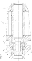
Figure 1 is a section, along a meridian section plane and with parts removed for clarity, which shows a preferred embodiment of the accessory assembly of a turbine engine, according to the present invention; and -
Figure 2 is a partial perspective cutaway view of a detail inFigure 1 . - Referring to
Figure 1 , reference numeral 1 indicates, as a whole, an accessory assembly of a turbine engine (partially shown). - The accessory assembly 1 comprises a
support structure 3 and a transmission shaft 4 (partially shown), which extends along anaxis 5 and is coupled to thestructure 3 in an angular rotational manner and axially secured by twomain bearings 6. Thebearings 6 are set axially apart, so as to be arranged on opposite sides of agear 7, which is fixed with respect to theshaft 4. In this specific case, thebearings 6 are friction bearings, as they perform a lubricant sealing function in addition to the support function for theshaft 4. In any case, thebearings 6 could be of the rolling type. - Preferably, the
shaft 4 is defined by a one-piece body, while thegear 7 is a separate part carried on theshaft 4. Alternatively, theshaft 4 could be composed of several parts fixed to each other and/or thegear 7 could be made in one piece with theshaft 4. - The
shaft 4 comprises anend portion 8, which extends from thebearing 6 towards the outside of thestructure 3. In particular,portion 8 comprises asection 9, housed in thestructure 3, and anend section 10, external to thestructure 3. -
Section 9 comprises a so-called "shear neck", indicated byreference numeral 11, defined by narrower cross-section with respect to the remaining part ofportion 8 and designed so as to define a point in which theshaft 4 breaks when the torque transmitted by theshaft 4 exceeds a design-defined threshold. Preferably, theshear neck 11 is arranged in an axial position that is immediately next to the coupling surface provided for thebearing 6. - Referring to
Figure 1 , the accessory assembly 1 further comprises agear 12, which is placed outside thestructure 3 and defines a motion inlet member, as it receives rotatory motion from a transmission gearbox, which is not shown. - As can be seen in
Figure 2 , thegear 12 comprises: ahub 13 coupled in a fixed position to theend section 10 in a manner not shown in detail; adisc 15, which lies on a radial plane with respect toaxis 5 and axially faces thestructure 3; atoothing 14 arranged along the outer circumference of thedisc 15; and a truncated cone shapedportion 16, which joins thedisc 15 to thehub 13. - Referring to
Figure 1 , according to one aspect of the present invention, thegear 12 and theend section 10 are still coupled to thestructure 3 by means of abearing 20 when theshear neck 11 breaks.Bearing 20 is arranged axially between theshear neck 11 and thehub 13 and is advantageously chosen so as to have a support capability both in the radial direction and in the axial direction. - Preferably, the axial position of
bearing 20 is aligned in a radial direction with the toothing 14 and thedisc 15. This configuration enables eliminating the development of tilting moments. - Preferably, bearing 20 is fitted on
section 9 and is suitable for directlycoupling section 9 to thestructure 3. Under normal operating conditions (i.e. when theshear neck 11 is intact), relatively broad radial play is provided between bearing 20 andsection 9 or between bearing 20 and thestructure 3, so as to avoid contact and, therefore, a hyperstatic condition. Friction between the surfaces in relative motion is always avoided under these conditions. - In other words, under normal operating conditions,
portion 8 is cantilever supported by bearing 6. Torque is transmitted from theshaft 4 and through theshear neck 11 to the accessories to be driven. When the torque on theshaft 4 exceeds the transmissible threshold limit set by design, it breaks at theshear neck 11 and thegear 12 thus becomes detached from the remaining part of theshaft 4. In this situation, bearing 20 intervenes and supportsportion 8, such that thegear 12 remains correctly supported in rotation and does not cause breakage of the transmission gearbox arranged upstream. - Preferably, bearing 20 is a friction bearing, which can be shaped and worked to obtain the required couplings.
- Alternatively, bearing 20 is a rolling bearing, with which correct coupling can be achieved by providing radial play between the outer ring of the bearing and its seat in the
structure 3. - From the foregoing, it is evident that the particular solution claimed has a relatively low number of components and is extremely compact in the axial direction, as the
gear 12 remains supported only at bearing 20 when theshear neck 11 breaks. - Furthermore, when the
shear neck 11 breaks, thegear 12 remain constrained to thestructure 3, without having to provide other additional support structures and/or additional transmission shafts. - In addition, the shape of
portion 16 contributes to radially align thetoothing 14 with bearing 20 and therefore to avoid tilting moments on bearing 20 when theshear neck 11 breaks. - Finally, it is evident that due to its simplicity, the solution described and illustrate herein can be mounted in a relatively easy and rapid manner.
- From the foregoing, it is evident that modifications and variants can be made regarding the accessory assembly 1 without departing from the scope as the defined by the appended claims.
- Furthermore, as mentioned above, the
end portion 8 could be defined by an element coupled to the remaining part of theshaft 4, for example by means of a spline coupling; and/or thegear 12 could be shaped differently from that shown by way of example.
Claims (7)
- An accessory assembly of a turbine engine, comprising:- a support structure (3);- a transmission shaft (4) coupled to said support structure (3) by means of a pair of main bearings (6) and comprising an end portion (8), which axially protrudes with respect to one of said main bearings (6) and comprises a shear neck (11) designed to break when the torque transmitted to such a shaft (4) exceeds a predetermined design threshold;- a gear (12) arranged outside said support structure (3), defining, in use, a motion inlet and coupled in a fixed position to said end portion (8);when said shear neck (11) breaks, said gear (12) remains coupled to said support structure by means of a single secondary bearing (20), which is distinct from said main bearings (6, 7) and is arranged axially between said shear neck (11) and said gear (12);
characterized in that radial clearance is provided at said secondary bearing (20), when said shear neck (11) is intact, so as to avoid a hyperstatic condition. - The accessory assembly according to claim 1, characterized in that said end portion (8) comprises an end section (10), external to said support structure (3); when said shear neck (11) breaks, said end section (10) remains coupled to said support structure by means of said secondary bearing (20).
- The accessory assembly according to claim 2, characterized in that said end portion (8) comprises a further section (9) housed in said support structure (3) and comprising said shear neck (11); said secondary bearing (20) being fitted on said further section (9).
- An accessory assembly according to claim 1, characterized in that the axial position of said secondary bearing (20) is radially aligned with the toothing of said gear (12).
- An assembly according to claim 1 or 4, characterized in that said secondary bearing (20) is defined by an element having a support capacity both in the radial direction and in the axial direction.
- An accessory assembly according to claim 5, characterized in that said secondary bearing (20) is a plain bearing.
- An accessory assembly according to any one of the preceding claims characterized in that said radial clearance is provided either between said secondary bearing (20) and said transmission shaft (4) or between said secondary bearing (20) and said support structure (3).
Applications Claiming Priority (2)
| Application Number | Priority Date | Filing Date | Title |
|---|---|---|---|
| ITTO20140856 | 2014-10-22 | ||
| PCT/IB2015/058163 WO2016063248A1 (en) | 2014-10-22 | 2015-10-22 | Accessory assembly of a turbine engine |
Publications (2)
| Publication Number | Publication Date |
|---|---|
| EP3209873A1 EP3209873A1 (en) | 2017-08-30 |
| EP3209873B1 true EP3209873B1 (en) | 2019-10-16 |
Family
ID=52273412
Family Applications (1)
| Application Number | Title | Priority Date | Filing Date |
|---|---|---|---|
| EP15804956.9A Active EP3209873B1 (en) | 2014-10-22 | 2015-10-22 | Accessory assembly of a turbine engine |
Country Status (6)
| Country | Link |
|---|---|
| US (1) | US10578166B2 (en) |
| EP (1) | EP3209873B1 (en) |
| JP (1) | JP2017534797A (en) |
| CN (1) | CN107076031B (en) |
| CA (1) | CA2965272A1 (en) |
| WO (1) | WO2016063248A1 (en) |
Families Citing this family (4)
| Publication number | Priority date | Publication date | Assignee | Title |
|---|---|---|---|---|
| US10578204B2 (en) * | 2016-08-23 | 2020-03-03 | United Technologies Corporation | Fused pilot for boss-mounted gearbox link |
| EP3382164A1 (en) * | 2017-03-28 | 2018-10-03 | Ge Avio S.r.l. | Output assembly for an accessory gearbox of a gas turbine engine |
| JP6809358B2 (en) * | 2017-04-24 | 2021-01-06 | いすゞ自動車株式会社 | Turbocharger shaft and turbocharger |
| US11722033B2 (en) * | 2021-08-24 | 2023-08-08 | Textron Innovations Inc. | Electric motor with backup bearing assembly |
Family Cites Families (7)
| Publication number | Priority date | Publication date | Assignee | Title |
|---|---|---|---|---|
| US3126723A (en) * | 1964-03-31 | Dugay | ||
| US3363415A (en) | 1965-02-01 | 1968-01-16 | Williams Res Corp | Gas turbine for automotive vehicles |
| FR1521603A (en) | 1967-03-09 | 1968-04-19 | Snecma | Improvements to torque limiting devices |
| GB2157772A (en) * | 1984-04-24 | 1985-10-30 | Holset Engineering Co | Bearing system |
| CN100483725C (en) * | 2006-07-28 | 2009-04-29 | 鸿富锦精密工业(深圳)有限公司 | Image sensing device packaging digital camera module group using the same |
| FR2905414B1 (en) * | 2006-08-29 | 2013-03-01 | Snecma | DEVICE FOR DRIVING THE ROTOR OF AN AUXILIARY EQUIPMENT OF A TURBOMOTEUR. |
| FR2911917B1 (en) * | 2007-01-31 | 2013-05-17 | Hispano Suiza Sa | DISTRIBUTED GAS TURBINE GENERATOR-STARTER ARCHITECTURE |
-
2015
- 2015-10-22 US US15/521,067 patent/US10578166B2/en active Active
- 2015-10-22 CA CA2965272A patent/CA2965272A1/en not_active Abandoned
- 2015-10-22 JP JP2017522142A patent/JP2017534797A/en active Pending
- 2015-10-22 CN CN201580056332.4A patent/CN107076031B/en active Active
- 2015-10-22 WO PCT/IB2015/058163 patent/WO2016063248A1/en active Application Filing
- 2015-10-22 EP EP15804956.9A patent/EP3209873B1/en active Active
Non-Patent Citations (1)
| Title |
|---|
| None * |
Also Published As
| Publication number | Publication date |
|---|---|
| JP2017534797A (en) | 2017-11-24 |
| WO2016063248A1 (en) | 2016-04-28 |
| US10578166B2 (en) | 2020-03-03 |
| CN107076031B (en) | 2019-07-30 |
| CA2965272A1 (en) | 2016-04-28 |
| US20170335896A1 (en) | 2017-11-23 |
| CN107076031A (en) | 2017-08-18 |
| EP3209873A1 (en) | 2017-08-30 |
Similar Documents
| Publication | Publication Date | Title |
|---|---|---|
| EP3209873B1 (en) | Accessory assembly of a turbine engine | |
| US7322180B2 (en) | Turbo-jet engine with fan integral with a drive shaft supported by first and second bearings | |
| EP1950378A1 (en) | Turbocharger rotor | |
| US9033107B2 (en) | Oil pump arrangement in a transmission | |
| US20120263523A1 (en) | Rotational assembly | |
| US20100192594A1 (en) | Compressed air starter for turbomachine | |
| US20210180654A1 (en) | Transmission | |
| US8900061B2 (en) | Clutch device | |
| US10875634B2 (en) | Drive train | |
| JP2015521266A (en) | Freewheel device | |
| US11668244B2 (en) | Decoupler for engine starter | |
| US10451143B2 (en) | Damper device | |
| US9300183B2 (en) | Rotating electric machine | |
| US10745117B2 (en) | Radially compliant quill shaft | |
| CN114008299B (en) | Assembly for supporting and guiding a drive shaft for an aircraft turbine engine | |
| EP3534027B1 (en) | Ball retention assembly for synchronous engagement clutch | |
| JP6050043B2 (en) | Constant velocity universal joint | |
| CN112747087A (en) | Planetary gear system, torsion safety device and method for operating transmission system | |
| JP2006242243A (en) | Coupling structure of automatic transmission and engine | |
| EP3581417B1 (en) | A transmission for a vehicle | |
| EP3707400B1 (en) | Transmission input shaft arrangement | |
| JP5077124B2 (en) | Torque transmission joint and electric power steering device | |
| JP2008169757A (en) | Belt drive mechanism | |
| RU2584109C1 (en) | Coupling of composite gas generator rotor of gas-turbine engine | |
| JP2016102569A (en) | Speed change gear |
Legal Events
| Date | Code | Title | Description |
|---|---|---|---|
| STAA | Information on the status of an ep patent application or granted ep patent |
Free format text: STATUS: THE INTERNATIONAL PUBLICATION HAS BEEN MADE |
|
| PUAI | Public reference made under article 153(3) epc to a published international application that has entered the european phase |
Free format text: ORIGINAL CODE: 0009012 |
|
| STAA | Information on the status of an ep patent application or granted ep patent |
Free format text: STATUS: REQUEST FOR EXAMINATION WAS MADE |
|
| 17P | Request for examination filed |
Effective date: 20170424 |
|
| AK | Designated contracting states |
Kind code of ref document: A1 Designated state(s): AL AT BE BG CH CY CZ DE DK EE ES FI FR GB GR HR HU IE IS IT LI LT LU LV MC MK MT NL NO PL PT RO RS SE SI SK SM TR |
|
| AX | Request for extension of the european patent |
Extension state: BA ME |
|
| DAV | Request for validation of the european patent (deleted) | ||
| DAX | Request for extension of the european patent (deleted) | ||
| GRAP | Despatch of communication of intention to grant a patent |
Free format text: ORIGINAL CODE: EPIDOSNIGR1 |
|
| STAA | Information on the status of an ep patent application or granted ep patent |
Free format text: STATUS: GRANT OF PATENT IS INTENDED |
|
| INTG | Intention to grant announced |
Effective date: 20190514 |
|
| GRAS | Grant fee paid |
Free format text: ORIGINAL CODE: EPIDOSNIGR3 |
|
| GRAA | (expected) grant |
Free format text: ORIGINAL CODE: 0009210 |
|
| STAA | Information on the status of an ep patent application or granted ep patent |
Free format text: STATUS: THE PATENT HAS BEEN GRANTED |
|
| AK | Designated contracting states |
Kind code of ref document: B1 Designated state(s): AL AT BE BG CH CY CZ DE DK EE ES FI FR GB GR HR HU IE IS IT LI LT LU LV MC MK MT NL NO PL PT RO RS SE SI SK SM TR |
|
| REG | Reference to a national code |
Ref country code: GB Ref legal event code: FG4D |
|
| REG | Reference to a national code |
Ref country code: CH Ref legal event code: EP |
|
| REG | Reference to a national code |
Ref country code: DE Ref legal event code: R096 Ref document number: 602015039975 Country of ref document: DE |
|
| REG | Reference to a national code |
Ref country code: IE Ref legal event code: FG4D |
|
| REG | Reference to a national code |
Ref country code: AT Ref legal event code: REF Ref document number: 1191485 Country of ref document: AT Kind code of ref document: T Effective date: 20191115 |
|
| REG | Reference to a national code |
Ref country code: NL Ref legal event code: MP Effective date: 20191016 |
|
| REG | Reference to a national code |
Ref country code: LT Ref legal event code: MG4D |
|
| REG | Reference to a national code |
Ref country code: AT Ref legal event code: MK05 Ref document number: 1191485 Country of ref document: AT Kind code of ref document: T Effective date: 20191016 |
|
| PG25 | Lapsed in a contracting state [announced via postgrant information from national office to epo] |
Ref country code: AT Free format text: LAPSE BECAUSE OF FAILURE TO SUBMIT A TRANSLATION OF THE DESCRIPTION OR TO PAY THE FEE WITHIN THE PRESCRIBED TIME-LIMIT Effective date: 20191016 Ref country code: LT Free format text: LAPSE BECAUSE OF FAILURE TO SUBMIT A TRANSLATION OF THE DESCRIPTION OR TO PAY THE FEE WITHIN THE PRESCRIBED TIME-LIMIT Effective date: 20191016 Ref country code: NL Free format text: LAPSE BECAUSE OF FAILURE TO SUBMIT A TRANSLATION OF THE DESCRIPTION OR TO PAY THE FEE WITHIN THE PRESCRIBED TIME-LIMIT Effective date: 20191016 Ref country code: BG Free format text: LAPSE BECAUSE OF FAILURE TO SUBMIT A TRANSLATION OF THE DESCRIPTION OR TO PAY THE FEE WITHIN THE PRESCRIBED TIME-LIMIT Effective date: 20200116 Ref country code: PT Free format text: LAPSE BECAUSE OF FAILURE TO SUBMIT A TRANSLATION OF THE DESCRIPTION OR TO PAY THE FEE WITHIN THE PRESCRIBED TIME-LIMIT Effective date: 20200217 Ref country code: FI Free format text: LAPSE BECAUSE OF FAILURE TO SUBMIT A TRANSLATION OF THE DESCRIPTION OR TO PAY THE FEE WITHIN THE PRESCRIBED TIME-LIMIT Effective date: 20191016 Ref country code: GR Free format text: LAPSE BECAUSE OF FAILURE TO SUBMIT A TRANSLATION OF THE DESCRIPTION OR TO PAY THE FEE WITHIN THE PRESCRIBED TIME-LIMIT Effective date: 20200117 Ref country code: NO Free format text: LAPSE BECAUSE OF FAILURE TO SUBMIT A TRANSLATION OF THE DESCRIPTION OR TO PAY THE FEE WITHIN THE PRESCRIBED TIME-LIMIT Effective date: 20200116 Ref country code: PL Free format text: LAPSE BECAUSE OF FAILURE TO SUBMIT A TRANSLATION OF THE DESCRIPTION OR TO PAY THE FEE WITHIN THE PRESCRIBED TIME-LIMIT Effective date: 20191016 Ref country code: LV Free format text: LAPSE BECAUSE OF FAILURE TO SUBMIT A TRANSLATION OF THE DESCRIPTION OR TO PAY THE FEE WITHIN THE PRESCRIBED TIME-LIMIT Effective date: 20191016 Ref country code: SE Free format text: LAPSE BECAUSE OF FAILURE TO SUBMIT A TRANSLATION OF THE DESCRIPTION OR TO PAY THE FEE WITHIN THE PRESCRIBED TIME-LIMIT Effective date: 20191016 |
|
| PG25 | Lapsed in a contracting state [announced via postgrant information from national office to epo] |
Ref country code: HR Free format text: LAPSE BECAUSE OF FAILURE TO SUBMIT A TRANSLATION OF THE DESCRIPTION OR TO PAY THE FEE WITHIN THE PRESCRIBED TIME-LIMIT Effective date: 20191016 Ref country code: RS Free format text: LAPSE BECAUSE OF FAILURE TO SUBMIT A TRANSLATION OF THE DESCRIPTION OR TO PAY THE FEE WITHIN THE PRESCRIBED TIME-LIMIT Effective date: 20191016 Ref country code: IS Free format text: LAPSE BECAUSE OF FAILURE TO SUBMIT A TRANSLATION OF THE DESCRIPTION OR TO PAY THE FEE WITHIN THE PRESCRIBED TIME-LIMIT Effective date: 20200224 |
|
| REG | Reference to a national code |
Ref country code: CH Ref legal event code: PL |
|
| PG25 | Lapsed in a contracting state [announced via postgrant information from national office to epo] |
Ref country code: AL Free format text: LAPSE BECAUSE OF FAILURE TO SUBMIT A TRANSLATION OF THE DESCRIPTION OR TO PAY THE FEE WITHIN THE PRESCRIBED TIME-LIMIT Effective date: 20191016 |
|
| REG | Reference to a national code |
Ref country code: DE Ref legal event code: R097 Ref document number: 602015039975 Country of ref document: DE |
|
| PG2D | Information on lapse in contracting state deleted |
Ref country code: IS |
|
| PG25 | Lapsed in a contracting state [announced via postgrant information from national office to epo] |
Ref country code: RO Free format text: LAPSE BECAUSE OF FAILURE TO SUBMIT A TRANSLATION OF THE DESCRIPTION OR TO PAY THE FEE WITHIN THE PRESCRIBED TIME-LIMIT Effective date: 20191016 Ref country code: LU Free format text: LAPSE BECAUSE OF NON-PAYMENT OF DUE FEES Effective date: 20191022 Ref country code: LI Free format text: LAPSE BECAUSE OF NON-PAYMENT OF DUE FEES Effective date: 20191031 Ref country code: CZ Free format text: LAPSE BECAUSE OF FAILURE TO SUBMIT A TRANSLATION OF THE DESCRIPTION OR TO PAY THE FEE WITHIN THE PRESCRIBED TIME-LIMIT Effective date: 20191016 Ref country code: MC Free format text: LAPSE BECAUSE OF FAILURE TO SUBMIT A TRANSLATION OF THE DESCRIPTION OR TO PAY THE FEE WITHIN THE PRESCRIBED TIME-LIMIT Effective date: 20191016 Ref country code: DK Free format text: LAPSE BECAUSE OF FAILURE TO SUBMIT A TRANSLATION OF THE DESCRIPTION OR TO PAY THE FEE WITHIN THE PRESCRIBED TIME-LIMIT Effective date: 20191016 Ref country code: CH Free format text: LAPSE BECAUSE OF NON-PAYMENT OF DUE FEES Effective date: 20191031 Ref country code: ES Free format text: LAPSE BECAUSE OF FAILURE TO SUBMIT A TRANSLATION OF THE DESCRIPTION OR TO PAY THE FEE WITHIN THE PRESCRIBED TIME-LIMIT Effective date: 20191016 Ref country code: EE Free format text: LAPSE BECAUSE OF FAILURE TO SUBMIT A TRANSLATION OF THE DESCRIPTION OR TO PAY THE FEE WITHIN THE PRESCRIBED TIME-LIMIT Effective date: 20191016 Ref country code: IS Free format text: LAPSE BECAUSE OF FAILURE TO SUBMIT A TRANSLATION OF THE DESCRIPTION OR TO PAY THE FEE WITHIN THE PRESCRIBED TIME-LIMIT Effective date: 20200216 |
|
| REG | Reference to a national code |
Ref country code: BE Ref legal event code: MM Effective date: 20191031 |
|
| PLBE | No opposition filed within time limit |
Free format text: ORIGINAL CODE: 0009261 |
|
| STAA | Information on the status of an ep patent application or granted ep patent |
Free format text: STATUS: NO OPPOSITION FILED WITHIN TIME LIMIT |
|
| PG25 | Lapsed in a contracting state [announced via postgrant information from national office to epo] |
Ref country code: SK Free format text: LAPSE BECAUSE OF FAILURE TO SUBMIT A TRANSLATION OF THE DESCRIPTION OR TO PAY THE FEE WITHIN THE PRESCRIBED TIME-LIMIT Effective date: 20191016 Ref country code: BE Free format text: LAPSE BECAUSE OF NON-PAYMENT OF DUE FEES Effective date: 20191031 Ref country code: SM Free format text: LAPSE BECAUSE OF FAILURE TO SUBMIT A TRANSLATION OF THE DESCRIPTION OR TO PAY THE FEE WITHIN THE PRESCRIBED TIME-LIMIT Effective date: 20191016 Ref country code: IT Free format text: LAPSE BECAUSE OF FAILURE TO SUBMIT A TRANSLATION OF THE DESCRIPTION OR TO PAY THE FEE WITHIN THE PRESCRIBED TIME-LIMIT Effective date: 20191016 |
|
| 26N | No opposition filed |
Effective date: 20200717 |
|
| PG25 | Lapsed in a contracting state [announced via postgrant information from national office to epo] |
Ref country code: IE Free format text: LAPSE BECAUSE OF NON-PAYMENT OF DUE FEES Effective date: 20191022 |
|
| PG25 | Lapsed in a contracting state [announced via postgrant information from national office to epo] |
Ref country code: SI Free format text: LAPSE BECAUSE OF FAILURE TO SUBMIT A TRANSLATION OF THE DESCRIPTION OR TO PAY THE FEE WITHIN THE PRESCRIBED TIME-LIMIT Effective date: 20191016 |
|
| PG25 | Lapsed in a contracting state [announced via postgrant information from national office to epo] |
Ref country code: CY Free format text: LAPSE BECAUSE OF FAILURE TO SUBMIT A TRANSLATION OF THE DESCRIPTION OR TO PAY THE FEE WITHIN THE PRESCRIBED TIME-LIMIT Effective date: 20191016 |
|
| PG25 | Lapsed in a contracting state [announced via postgrant information from national office to epo] |
Ref country code: HU Free format text: LAPSE BECAUSE OF FAILURE TO SUBMIT A TRANSLATION OF THE DESCRIPTION OR TO PAY THE FEE WITHIN THE PRESCRIBED TIME-LIMIT; INVALID AB INITIO Effective date: 20151022 Ref country code: MT Free format text: LAPSE BECAUSE OF FAILURE TO SUBMIT A TRANSLATION OF THE DESCRIPTION OR TO PAY THE FEE WITHIN THE PRESCRIBED TIME-LIMIT Effective date: 20191016 |
|
| PG25 | Lapsed in a contracting state [announced via postgrant information from national office to epo] |
Ref country code: TR Free format text: LAPSE BECAUSE OF FAILURE TO SUBMIT A TRANSLATION OF THE DESCRIPTION OR TO PAY THE FEE WITHIN THE PRESCRIBED TIME-LIMIT Effective date: 20191016 |
|
| PG25 | Lapsed in a contracting state [announced via postgrant information from national office to epo] |
Ref country code: MK Free format text: LAPSE BECAUSE OF FAILURE TO SUBMIT A TRANSLATION OF THE DESCRIPTION OR TO PAY THE FEE WITHIN THE PRESCRIBED TIME-LIMIT Effective date: 20191016 |
|
| P01 | Opt-out of the competence of the unified patent court (upc) registered |
Effective date: 20230418 |
|
| PGFP | Annual fee paid to national office [announced via postgrant information from national office to epo] |
Ref country code: GB Payment date: 20230920 Year of fee payment: 9 |
|
| PGFP | Annual fee paid to national office [announced via postgrant information from national office to epo] |
Ref country code: FR Payment date: 20230920 Year of fee payment: 9 |
|
| PGFP | Annual fee paid to national office [announced via postgrant information from national office to epo] |
Ref country code: DE Payment date: 20230920 Year of fee payment: 9 |