Technical Field
-
The present disclosure relates to a multiple-shell tank and a ship on which a multiple-shell tank is mounted.
Background Art
-
A ship on which a multiple-shell tank as a cargo tank is mounted has been known. The multiple-shell tank includes shells including an inner shell and an outer shell. The inner shell stores low temperature fluid-state cargo, such as a liquefied gas. The outer shell covers the inner shell. It is known that to improve a heat insulating property, a vacuum space is formed in an inter-shell region of the multiple-shell tank. PTL 1 discloses a double-shell tank mounted on a ship.
-
The double-shell tank disclosed in PTL 1 includes: an inner shell storing a liquefied gas; an outer shell surrounding the inner shell, a vacuum space being formed between the inner shell and the outer shell; at least one metal sheet attached to the inner shell such that at least a part of the metal sheet is opposed to a bottom surface of the inner shell; a gas molecule adsorbing material placed on the metal sheet; and a heat insulation sheet covering the inner shell and the metal sheet. The heat insulation sheet includes radiation shield films and low heat conductive sheet-shaped spacers which are alternately laminated on each other.
Citation List
Patent Literature
-
Summary of Invention
Technical Problem
-
According to the double-shell tank of PTL 1, the inter-shell region between the inner shell and the outer shell is set to a high vacuum state. With this, the intrusion of radiant heat is prevented, and natural convection is prevented. Thus, a high heat insulating effect is obtained. However, it takes time to subject the inter-shell region having a huge volume to vacuum drawing, and this may become a factor which increases a time required for manufacture and a time required for maintenance. Moreover, a shell wall is required to have an adequate thickness to obtain vacuum resistance, and this may become a factor which increases the weight of the tank. Furthermore, a large number of reinforcing members need to be added to the tank, and the structure of the tank is complex. Therefore, the manufacture is extremely difficult.
-
The present disclosure was made under these circumstances, and an object of the present disclosure is to realize high heat insulation performance of a multiple-shell tank storing a liquefied gas, without depending on setting an inter-shell region between an inner shell and an outer shell to a high vacuum state.
Solution to Problem
-
A multiple-shell tank according to one aspect of the present disclosure includes: an inner shell storing a liquefied gas; an outer shell including a single shell or multiple shells and located outside the inner shell with a gap so as to surround the inner shell; planar thermal insulators that are fixed to two or more surfaces among an outer surface of the inner shell, an inner surface of the outer shell, and an outer surface of the outer shell so as to cover the two or more surfaces and block heat conduction and heat convection. A gas is filled in an inter-shell region or inter-shell regions.
-
Moreover, a ship according to one aspect of the present disclosure includes: a hull; and the multiple-shell tank mounted on the hull.
-
According to the multiple-shell tank and the ship configured as above, heat conduction and heat convection are blocked by two or more heat insulating layers that are the planar thermal insulators. With this, even when the inter-shell region is filled with the gas, the tank wall of the multiple-shell tank can obtain adequately high heat insulation performance.
Advantageous Effects of Invention
-
According to the present disclosure, the multiple-shell tank that stores the liquefied gas can obtain high heat insulation performance without depending on setting the inter-shell region between the inner shell and the outer shell to a high vacuum state.
Brief Description of Drawings
-
- FIG. 1 is a side view showing an entire configuration of a ship on which multiple-shell tanks according to one embodiment of the present disclosure are mounted.
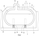
- FIG. 2 is a sectional view for explaining the structure of the multiple-shell tank mounted on the ship.
- FIG. 3 is a sectional view of the multiple-shell tank according to First Example.
- FIG. 4 is a diagram for explaining a method of fixing a planar thermal insulator.
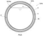
- FIG. 5 is a sectional view of the multiple-shell tank according to First Example in which an inter-shell region is filled with a powdered thermal insulator.
- FIG. 6 is a sectional view of the multiple-shell tank according to Second Example.
- FIG. 7 is a sectional view of the multiple-shell tank according to Third Example.
- FIG. 8 is a sectional view of the multiple-shell tank according to Fourth Example.
- FIG. 9 is a sectional view of the multiple-shell tank according to Fifth Example.
- FIG. 10 is a sectional view of the multiple-shell tank according to Sixth Example.
Description of Embodiments
-
FIG. 1 shows a ship 1 on which multiple-shell tanks 3 according to one embodiment of the present disclosure are mounted. The ship 1 includes a hull 2 and two multiple-shell tanks 3 mounted on the hull 2. The multiple-shell tanks 3 are cargo tanks for transportation of a low temperature fluid. In the present embodiment, the multiple-shell tanks 3 are lined up in a ship longitudinal direction. However, when the width of the ship is large, the multiple-shell tanks 3 may be lined up in a ship width direction. The number of multiple-shell tanks 3 mounted on the hull 2 may be one or may be three or more.
-
The two multiple-shell tanks 3 are substantially the same in structure as each other. In the present embodiment, the multiple-shell tank 3 is configured as a double-shell tank. As shown in FIG. 2, each multiple-shell tank 3 includes: an inner shell 4 that stores cargo; and an outer shell 5 that wraps the inner shell 4. The inner shell 4 and the outer shell 5 are spaced apart from each other substantially uniformly. An inter-shell region 30 is located between the inner shell 4 and the outer shell 5 in a thickness direction of a tank wall. A heat insulation structure of the tank wall of the multiple-shell tank 3 will be described later in detail.
-
The cargo may be a liquefied gas, such as a liquefied petroleum gas (LPG, about -45°C), a liquefied ethylene gas (LEG, about -100°C), a liquefied natural gas (LNG, about -160°C), liquefied oxygen (LO2, about -180°C), liquefied hydrogen (LH2, about -250°C), or liquefied helium (LHe, about -270°C). However, the cargo does not necessarily have to be a liquid and may be a gas.
-
The inner shell 4 includes an inner shell main body 41 and an inner shell dome 42. The inner shell main body 41 has a cylindrical shape that is long in a horizontal direction. The inner shell dome 42 projects upward from the inner shell main body 41. In the present embodiment, an axial direction of the inner shell main body 41 is parallel to the ship longitudinal direction. In the present embodiment, an axial direction of the inner shell dome 42 is parallel to a vertical direction. However, the axial direction of the inner shell dome 42 may be slightly inclined relative to the vertical direction.
-
The outer shell 5 includes an outer shell main body 51 and an outer shell dome 52. The outer shell main body 51 has a cylindrical shape that is long in the horizontal direction. The outer shell dome 52 projects upward from the outer shell main body 51. The outer shell main body 51 surrounds the inner shell main body 41. The outer shell dome 52 surrounds the inner shell dome 42. As with the inner shell main body 41, an axial direction of the outer shell main body 51 is parallel to the ship longitudinal direction. As with the inner shell dome 42, an axial direction of the outer shell dome 52 is parallel to the vertical direction. However, each of the inner shell main body 41 and the outer shell main body 51 does not necessarily have to have a cylindrical shape that is long in the horizontal direction and may have a cylindrical shape that is long in the vertical direction. Or, each of the inner shell main body 41 and the outer shell main body 51 may have a spherical shape, a cube shape, or a cuboid shape.
-
The hull 2 includes two cargo holds 21 that are open upward. The cargo holds 21 are lined up in the ship longitudinal direction and are separated from each other by a dividing wall 22. Then, lower portions of the multiple-shell tanks 3 are inserted into the respective cargo holds 21.
-
A pair of saddles 25 are located in each of the cargo holds 21. The saddles 25 are spaced apart from each other in the ship longitudinal direction. The saddles 25 support the outer shell main body 51 of the outer shell 5 of the multiple-shell tank 3. Moreover, a pair of supports 35 are located between the inner shell 4 and the outer shell 5 of the multiple-shell tank 3. The supports 35 support the inner shell main body 41. In the present embodiment, the supports 35 are located at the same positions as the saddles 25. However, the supports 35 may be located at different positions from the saddles 25.
-
Tank covers 6 are located above the respective multiple-shell tanks 3. Each of the tank covers 6 covers the corresponding multiple-shell tank 3 from above. A holding space 7 in which an inactive gas is filled is located between the hull 2 and the tank cover 6. The outer shell main body 51 of the outer shell 5 is located under the tank cover 6, and the outer shell dome 52 of the outer shell 5 penetrates the tank cover 6.
Heat Insulation Structure of Multiple-shell Tank 3
-
The following will describe a heat insulation structure included in the multiple-shell tank 3 configured as above. FIG. 3 is a sectional view of the multiple-shell tank 3 according to First Example. As shown in FIG. 3, the multiple-shell tank 3 includes: the inner shell 4 storing a liquefied gas; the outer shell 5 including a single shell or multiple shells and located outside the inner shell 4 with a gap so as to surround the inner shell 4; and planar thermal insulators 9 that are located so as to cover two or more surfaces among an outer surface of the inner shell 4, an inner surface of the outer shell 5, and an outer surface of the outer shell 5 and block heat radiation, heat conduction, and heat convection.
-
Each of the planar thermal insulators 9 has a panel shape. The planar thermal insulator 9 has a thickness that is 0.01 time or more and one time or less a gap between the inner shell 4 and the outer shell 5 (first outer shell 5A) located immediately outside the inner shell 4. The planar thermal insulator 9 may be a multiple-layer panel in which a thermal insulator is sandwiched between plate-shaped base materials. However, the shape of the planar thermal insulator 9 is not limited to the panel shape and may be a sheet shape. Examples of such planar thermal insulator 9 include a urethane foam panel, an aerogel sheet, and sheet-shaped glass wool.
-
The planar thermal insulator 9 is fixed to a surface of the inner shell 4 or a surface of the outer shell 5 by a fixture. As shown in FIG. 4, a base plate 81 made of metal is joined to the inner shell 4 (or the outer shell 5) by, for example, welding. A stud bolt 82 is joined to the base plate 81 by a screw structure, welding, or the like. The material of the stud bolt 82 is not especially limited. For example, it is desirable that the material of the stud bolt 82 be a low heat conductive material, such as glass fiber reinforced plastic (GFRP). The stud bolt 82 is inserted through a hole of the planar thermal insulator 9 and screwed into a nut 83. In this example, the stud bolt 82 and the nut 83 correspond to the fixture. However, the planar thermal insulator 9 may be fixed to the surface of the inner shell 4 or the surface of the outer shell 5 by an adhesive or by a self-adhesive function of urethane foam.
-
The inter-shell region 30 (first inter-shell region 30A) between the inner shell 4 and the outer shell 5 (first outer shell 5A) located immediately outside the inner shell 4 is filled with a low temperature gas (such as a gas generated by evaporation of the liquefied gas as the cargo). The gas filled in the first inter-shell region 30A may be the gas that has been generated by the evaporation and flowed from the inner shell 4 into the first inter-shell region 30A through communication between the inner shell 4 and the first inter-shell region 30A.
-
The pressure of the first inter-shell region 30A is 1 kPa or more. The pressure of the first inter-shell region 30A is adequately higher than that of conventional vacuum insulation. Moreover, the pressure of the first inter-shell region 30A may be 1 kPa or more and negative pressure with respect to atmospheric pressure. In this case, the degree of vacuum of the first inter-shell region 30A is adequately lower than that of the conventional vacuum insulation.
-
The first inter-shell region 30A includes a void 31 in the thickness direction of the tank wall of the multiple-shell tank 3. The planar thermal insulator 9 does not exist in the void 31. The void 31 is utilized as a space for work and has an adequate size for work. The void 31 may be utilized for the arrangement of pipes. The size of the void 31 in the thickness direction of the tank wall is, for example, 0.1 time or more and 0.99 time or less the gap of the inter-shell region 30. When the void 31 is set to be large, a worker can get into the void 31 during construction and perform work of fixing the planar thermal insulators 9 to the inner shell 4 and the outer shell 5. Moreover, the worker can get into the void 31 during maintenance, inspect the planar thermal insulators 9, and maintain the planar thermal insulators 9. In the present embodiment, since each planar thermal insulator 9 is fixed to the surface of the inner shell 4 or the surface of the outer shell 5 by the fixture, it is especially useful to include the void 31 in which the planar thermal insulators 9 are moved, and the fixtures are handled. On the other hand, when the planar thermal insulator 9 and the void 31 are set to be large, the outer shell 5 becomes large, and the cost may be influenced by the increases in the installation space and the weight of the tank. According to the multiple-shell tank 3, the thickness of the planar thermal insulator 9 and the sizes of the inter-shell region 30 and the void 31 can be flexibly selected in accordance with required heat protection performance and restriction of the installation space.
-
As shown in FIG. 5, a powdered thermal insulator 95, such as pearlite, may be filled in the void 31 of the first inter-shell region 30A. With this, the heat insulation performance of the multiple-shell tank 3 can be further improved.
-
Hereinafter, examples of the arrangement of the planar thermal insulators 9 in the multiple-shell tank 3 will be described. Desirably, the planar thermal insulators 9 include: a first planar thermal insulator located so as to cover one of an inner surface and outer surface of the first outer shell 5A located immediately outside the inner shell 4 in the outer shell 5; and a second planar thermal insulator located so as to cover the surface which is not covered with the first planar thermal insulator, among the outer surface of the inner shell 4, the inner surface of the outer shell 5, and the outer surface of the outer shell 5.
-
The heat protection performance of the first planar thermal insulator and the heat protection performance of the second planar thermal insulator may be different from each other in accordance with places where the planar thermal insulators 9 are located. The types and thicknesses of the first planar thermal insulator and the second planar thermal insulator are suitably adjusted in accordance with the first inter-shell region 30A and a second inter-shell region 30B which are different from each other in terms of a temperature condition and an atmosphere condition. With this, even when the inter-shell region 30 is not in a high vacuum state, the multiple-shell tank 3 can obtain adequately high heat insulation performance.
First Example
-
A multiple-shell tank 3A shown in FIG. 3 is a double-shell tank and includes the inner shell 4 and the outer shell 5 that is a single shell. The planar thermal insulator 9 is fixed to the outer surface of the inner shell 4 so as to cover the outer surface of the inner shell 4. Moreover, the planar thermal insulator 9 is fixed to the outer surface of the outer shell 5 so as to cover the outer surface of the outer shell 5.
Second Example
-
A multiple-shell tank 3B shown in FIG. 6 is a double-shell tank and includes the inner shell 4 and the outer shell 5 that is a single shell. The planar thermal insulator 9 is fixed to the inner surface of the outer shell 5 so as to cover the inner surface of the outer shell 5. Moreover, the planar thermal insulator 9 is fixed to the outer surface of the outer shell 5 so as to cover the outer surface of the outer shell 5.
Third Example
-
A multiple-shell tank 3C shown in FIG. 7 is a double-shell tank and includes the inner shell 4 and the outer shell 5 that is a single shell. The planar thermal insulator 9 is fixed to the inner surface of the inner shell 4 so as to cover the outer surface of the inner shell 4. Moreover, the planar thermal insulator 9 is fixed to the inner surface of the outer shell 5 so as to cover the inner surface of the outer shell 5. Furthermore, the planar thermal insulator 9 is fixed to the outer surface of the outer shell 5 so as to cover the outer surface of the outer shell 5.
Fourth Example
-
A multiple-shell tank 3D shown in FIG. 8 is a triple-shell tank and includes the inner shell 4 and the outer shell 5 that is a double shell. The double outer shell 5 includes: a first outer shell 5A located immediately outside the inner shell 4; and a second outer shell 5B located outside the first outer shell 5A. An inactive gas (such as nitrogen) which is higher in boiling point than the gas filled in the first inter-shell region 30A is filled in the inter-shell region 30 (second inter-shell region 30B) between the first outer shell 5A and the second outer shell 5B.
-
In the multiple-shell tank 3D, the planar thermal insulator 9 is fixed to the outer surface of the inner shell 4 so as to cover the outer surface of the inner shell 4. Moreover, the planar thermal insulator 9 is fixed to the outer surface of the first outer shell 5A so as to cover the outer surface of the first outer shell 5A. Furthermore, the planar thermal insulator 9 is fixed to the outer surface of the second outer shell 5B so as to cover the outer surface of the second outer shell 5B. In the multiple-shell tank 3D, instead of the planar thermal insulator 9 covering the outer surface of the first outer shell 5A, the planar thermal insulator 9 may be fixed to the inner surface of the first outer shell 5A so as to cover the inner surface of the first outer shell 5A. Moreover, in the multiple-shell tank 3D, instead of the planar thermal insulator 9 covering the outer surface of the second outer shell 5B, the planar thermal insulator 9 may be fixed to the inner surface of the second outer shell 5B so as to cover the inner surface of the second outer shell 5B.
Fifth Example
-
A multiple-shell tank 3E shown in FIG. 9 is a triple-shell tank and includes the inner shell 4 and the outer shell 5 that is a double shell (the first outer shell 5A and the second outer shell 5B). In the multiple-shell tank 3E, the planar thermal insulator 9 is fixed to the inner surface of the first outer shell 5A so as to cover the inner surface of the first outer shell 5A. Moreover, the planar thermal insulator 9 is fixed to the outer surface of the first outer shell 5A so as to cover the inner surface of the first outer shell 5A. In the multiple-shell tank 3E, in addition to the inner surface and outer surface of the first outer shell 5A, at least one of the outer surface of the inner shell 4, the inner surface of the second outer shell 5B, and the outer surface of the second outer shell 5B may be covered with the planar thermal insulator 9.
Sixth Example
-
A multiple-shell tank 3F shown in FIG. 10 is a triple-shell tank and includes the inner shell 4 and the outer shell 5 that is a double shell (the first outer shell 5A and the second outer shell 5B). In the multiple-shell tank 3F, the planar thermal insulator 9 is fixed to the inner surface of the first outer shell 5A so as to cover the inner surface of the first outer shell 5A. Moreover, the planar thermal insulator 9 is fixed to the inner surface of the second outer shell 5B so as to cover the inner surface of the second outer shell 5B. In the multiple-shell tank 3F, instead of the planar thermal insulator 9 covering the inner surface of the first outer shell 5A, the planar thermal insulator 9 may be fixed to the outer surface of the first outer shell 5A so as to cover the outer surface of the first outer shell 5A. Moreover, in the multiple-shell tank 3F, instead of the planar thermal insulator 9 covering the inner surface of the second outer shell 5B, the planar thermal insulator 9 may be fixed to the outer surface of the second outer shell 5B so as to cover the outer surface of the second outer shell 5B. Furthermore, in the multiple-shell tank 3F, instead of the planar thermal insulator 9 covering the inner surface of the second outer shell 5B, the planar thermal insulator 9 may be fixed to the outer surface of the inner shell 4 so as to cover the outer surface of the inner shell 4.
Conclusion
-
As described above, the multiple-shell tank 3 of the present embodiment includes: the inner shell 4 storing the liquefied gas; the outer shell 5 including a single shell or multiple shells and located outside the inner shell 4 with a gap so as to surround the inner shell 4; and the planar thermal insulators 9 that are fixed to two or more surfaces among the outer surface of the inner shell 4, the inner surface of the outer shell 5, and the outer surface of the outer shell 5 so as to cover the two or more surfaces and block heat conduction and heat convection. The gas is filled in the inter-shell region 30 or the inter-shell regions 30.
-
Examples of the arrangement of the planar thermal insulators 9 when the outer shell 5 is a single shell are as below.
First Example
-
The planar thermal insulators 9 are located so as to cover the outer surface of the inner shell 4 and the inner surface of the outer shell 5.
Second Example
-
The planar thermal insulators 9 are located so as to cover two surfaces that are the outer surface of the inner shell 4 and the outer surface of the outer shell 5.
Third Example
-
The planar thermal insulators 9 are located so as to cover two surfaces that are the inner surface of the outer shell 5 and the outer surface of the outer shell 5.
Fourth Example
-
The planar thermal insulators 9 are located so as to cover three surfaces that are the outer surface of the inner shell 4, the inner surface of the outer shell 5, and the outer surface of the outer shell 5.
-
Moreover, the ship 1 according to the present embodiment includes the hull 2 and the multiple-shell tank 3 mounted on the hull 2.
-
According to the multiple-shell tank 3 and the ship 1 configured as above, heat conduction and heat convection are blocked by two heat insulating layers that are the planar thermal insulators 9. With this, even when the inter-shell region 30 is filled with the gas, the tank wall of the multiple-shell tank 3 can obtain adequately high heat insulation performance. Moreover, according to the multiple-shell tank 3 configured as above, the planar thermal insulator 9 is fixed to the surface of the inner shell 4 or the surface of the outer shell 5. Therefore, even when the thermal contraction of the inner shell 4 and the outer shell 5 occurs, positional displacement or deviation of the planar thermal insulator 9 relative to the surface to which the planar thermal insulator 9 is attached hardly occurs. Therefore, the reliability of the heat insulation performance at respective portions of the tank wall can be improved.
-
In the multiple-shell tank 3 configured as above, the pressure of the inter-shell region 30 (first inter-shell region 30A) between the inner shell 4 and the outer shell 5 (first outer shell 5A) located immediately outside the inner shell 4 may be 1 kPa or more.
-
Moreover, the pressure of the first inter-shell region 30A may be negative pressure with respect to atmospheric pressure. With this, the tank wall of the multiple-shell tank 3 can obtain further high heat insulation performance.
-
In the multiple-shell tank 3 configured as above, each of the planar thermal insulators 9 may have a panel shape.
-
In the multiple-shell tank 3 configured as above, each of the planar thermal insulators 9 may be fixed by the fixture (the stud bolt 82 and the nut 83) to the surface to be covered with the planar thermal insulator 9.
-
Since the planar thermal insulator 9 is fixed by the fixture as above, attaching and detaching of the planar thermal insulator 9 are relatively easy, and therefore, on-site construction work can be simplified.
-
In the multiple-shell tank 3 configured as above, each of the inter-shell regions 30 may include the void 31 for work in the thickness direction. Herein, the void 31 denotes a space of the inter-shell region 30 which is not occupied by the planar thermal insulator 9 and through which objects (such as workers and pipes) other than gas can pass.
-
As above, the inter-shell region 30 includes the void 31. Therefore, during construction, a worker can utilize the void 31 to perform work of attaching the planar thermal insulators 9, piping work, and the like. Moreover, during maintenance, the planar thermal insulator 9 can be inspected by introducing inspection equipment to the void 31, and a worker can perform work of, for example, replacing the planar thermal insulators 9 by utilizing the void 31.
-
In the multiple-shell tank 3 configured as above, it is desirable that the planar thermal insulators 9 include: the first planar thermal insulator located so as to cover one of the inner surface and outer surface of the first outer shell 5A that is included in the outer shell 5 and is located immediately outside the inner shell 4; and the second planar thermal insulator located so as to cover the surface which is not covered with the first planar thermal insulator, among the outer surface of the inner shell 4, the inner surface of the outer shell 5, and the outer surface of the outer shell 5.
-
With this, thermal insulation is especially intensively realized inside and outside the first outer shell SA.
-
The foregoing has described a preferred embodiment of the present disclosure. Modifications of specific structures and/or functional details of the above embodiment may be included in the present disclosure as long as they are within the scope of the present disclosure. The above configuration may be changed as below, for example.
-
For example, in the above embodiment, the multiple-shell tank 3 is mounted on the ship 1. However, the structure of the multiple-shell tank 3 may be applied to a liquefied gas storage tank placed on land.
Reference Signs List
-
- 1
- ship
- 2
- hull
- 3, 3A to 3F
- multiple-shell tank
- 4
- inner shell
- 5
- outer shell
- 5A
- first outer shell
- 9
- planar thermal insulator
- 30
- inter-shell region
- 31
- void