EP4269207A1 - Fixed cover, front cover, and rail vehicle - Google Patents
Fixed cover, front cover, and rail vehicle Download PDFInfo
- Publication number
- EP4269207A1 EP4269207A1 EP21944876.8A EP21944876A EP4269207A1 EP 4269207 A1 EP4269207 A1 EP 4269207A1 EP 21944876 A EP21944876 A EP 21944876A EP 4269207 A1 EP4269207 A1 EP 4269207A1
- Authority
- EP
- European Patent Office
- Prior art keywords
- hood
- lateral
- fixed
- hood body
- bodies
- Prior art date
- Legal status (The legal status is an assumption and is not a legal conclusion. Google has not performed a legal analysis and makes no representation as to the accuracy of the status listed.)
- Granted
Links
Images

Classifications
-
- B—PERFORMING OPERATIONS; TRANSPORTING
- B61—RAILWAYS
- B61D—BODY DETAILS OR KINDS OF RAILWAY VEHICLES
- B61D17/00—Construction details of vehicle bodies
- B61D17/02—Construction details of vehicle bodies reducing air resistance by modifying contour ; Constructional features for fast vehicles sustaining sudden variations of atmospheric pressure, e.g. when crossing in tunnels
-
- B—PERFORMING OPERATIONS; TRANSPORTING
- B61—RAILWAYS
- B61D—BODY DETAILS OR KINDS OF RAILWAY VEHICLES
- B61D17/00—Construction details of vehicle bodies
- B61D17/04—Construction details of vehicle bodies with bodies of metal; with composite, e.g. metal and wood body structures
- B61D17/043—Construction details of vehicle bodies with bodies of metal; with composite, e.g. metal and wood body structures connections between superstructure sub-units
-
- Y—GENERAL TAGGING OF NEW TECHNOLOGICAL DEVELOPMENTS; GENERAL TAGGING OF CROSS-SECTIONAL TECHNOLOGIES SPANNING OVER SEVERAL SECTIONS OF THE IPC; TECHNICAL SUBJECTS COVERED BY FORMER USPC CROSS-REFERENCE ART COLLECTIONS [XRACs] AND DIGESTS
- Y02—TECHNOLOGIES OR APPLICATIONS FOR MITIGATION OR ADAPTATION AGAINST CLIMATE CHANGE
- Y02T—CLIMATE CHANGE MITIGATION TECHNOLOGIES RELATED TO TRANSPORTATION
- Y02T30/00—Transportation of goods or passengers via railways, e.g. energy recovery or reducing air resistance
Definitions
- the present application relates to railway vehicle technologies, and in particular, to a fixed hood, a front hood and a railway vehicle.
- a front hood as one of important components of a high-speed rail vehicle, has the following main functions: in case that the front hood is opened, operations such as coupler reconnection, emergency rescue and equipment maintenance can be performed on the rail vehicle; in case that the front hood is closed, the rail vehicle may have a streamlined shape during operation at a high speed, which decreases running resistance and improves safety and stability.
- the front hood generally is consisted of two parts: a fixed hood being stationary relative to the vehicle and an opening and closing hood moving relative to the vehicle.
- a rail train is easily subjected to impacts from foreign objects such as gravel, stones and birds.
- the front hood is impacted and damaged severely because of locating at the front end of the train.
- functions of the front hood can be quickly restored by replacing it with a new front hood.
- the fixed hood is connected to the vehicle body through fasteners, which has a huge overall volume.
- the front hood is replaced, much external equipment such as couplers, obstacle removers, and opening or closing mechanisms need to be removed.
- the external equipment needs to be restored one by one and the entire vehicle is painted and repaired together with the front, which makes overall replacement process being time-consuming and complicated. Therefore, a mounting structure of a traditional fixed hood cannot meet the requirements of a high-speed train.
- the present application provides a fixed hood, which can be quickly replaced under the premise of avoiding the removal of other external devices.
- An embodiment of the present application provides a fixed hood, including:
- the mounting frame includes a first frame and a second frame arranged symmetrically, and each of the first frame and the second frame includes a first support longitudinal bar, a second support longitudinal bar, a first connecting crossbar, a second connecting crossbar and a third connecting crossbar, the first connecting crossbar, the second connecting crossbar and the third connecting crossbar are arranged along a height direction of the mounting frame at intervals, and both ends of the first connecting crossbar, both ends of the second connecting crossbar and both ends of the third connecting crossbar are connected with the first support longitudinal bar and the second support longitudinal bar respectively.
- the first support longitudinal bar is arranged close to the front-end opening, and the second support longitudinal bar is arranged far away from the front-end opening; a plurality of the vehicle body mounting seats are arranged along a length direction of the second support longitudinal bar at intervals, each of the plurality of the vehicle body mounting seats includes a first mounting portion and a vehicle body connecting portion, the first mounting portion and the vehicle body connecting portion are connected to each other to form an L-shaped structure; the first mounting portion is fixedly connected to the second support longitudinal bar, and the vehicle body connecting portion is detachably connected to the vehicle body front-end bearing structure through a first connector.
- a plurality of first connecting plates extending toward the top hood body are fixedly arranged on the first connecting crossbar, and the plurality of first connecting plates are arranged along a length direction of the first connecting crossbar at intervals; connecting folded edges are arranged at an end of each of the plurality of first connecting plates close to the top hood body; first pre-embedded bosses being in one-to-one correspondence with the plurality of the first connecting plates are arranged inside the top hood body, and each of the first pre-embedded bosses is detachably connected to each of the connecting folded edges through a second connector.
- a plurality of second connecting plates extending toward the top hood body are fixedly arranged on the third connecting crossbar, and the plurality of second connecting plates are arranged along a length direction of the third connecting crossbar at intervals; second pre-embedded bosses being in one-to-one correspondence with the plurality of second connecting plates are arranged inside the bottom hood body, and each of the second pre-embedded bosses is detachably connected to each of the plurality of second connecting plates through a third connector.
- a plurality of first connecting seats are fixedly arranged on the first connecting crossbar, and the plurality of first connecting seats are arranged along the length direction of the first connecting crossbar at intervals, each of the first connecting seats is a " ⁇ "-shaped structure protruding toward the direction of the lateral hood bodies, and each of the first connecting seats is detachably connected to the lateral hood bodies through a first adjusting connector; and a plurality of second connecting seats are fixedly arranged on the second connecting crossbar, and the plurality of second connecting seats are arranged along a length direction of the second connecting crossbar at intervals, each of the second connecting seats is a " ⁇ "-shaped structure protruding toward the direction of the lateral hood bodies, and each of the second connecting seats is detachably connected to the lateral hood body through a second adjusting connector.
- the first adjusting connector includes a first connecting screw and a first floating nut engaged with the first connecting screw, the first floating nut is fixed inside the first connecting seat, the first connecting screw successively passes through the lateral hood bodies, and the first connecting seat and is connected with the first floating nut; and the second adjusting connector includes a second connecting screw and a second floating nut engaged with the second connecting screw, the second floating nut is fixed inside the second connecting seat, the second connecting screw successively passes through both the lateral hood bodies, and the second connecting seat and is connected with the second floating nut.
- the top hood body is provided with top hood body flanges corresponding to the lateral hood bodies, the lateral hood bodies are provided with a first lateral hood body flange engaged with the top hood body flange, and the first lateral hood body flange and the top hood body flange are spliced together.
- each of the top hood body flanges is provided with a first limiting plate for limiting a mounting position of each lateral hood body, and the first limiting plate is arranged at a position on each top hood body flange close to the front-end opening.
- a vehicle body connecting flange is provided on a side of the top hood body away from the front-end opening, the vehicle body connecting flange includes a plurality of connecting holes arranged along a length direction of the vehicle body connecting flange at intervals, and each of the plurality of connecting holes is detachably connected to the vehicle body front-end bearing structure through a fourth connector.
- the bottom hood body is provided with bottom hood body flanges corresponding to the lateral hood bodies, and each of the lateral hood bodies is provided with a second lateral hood body flange engaged with the bottom hood body, and the second lateral hood body flange and the bottom hood body flange are spliced together.
- each of the bottom hood body flanges is provided with a second limiting plate for limiting a mounting position of each lateral hood body, and the second limiting plate is arranged at a position on each bottom hood body flange close to the front-end opening.
- a limiting bayonet corresponding to the second limiting plate is arranged on the second lateral hood body flange, and the second limiting plate is snapped into in the limiting bayonet.
- An embodiment of the present application further provides a front hood, including the fixed hood according to the above embodiments.
- An embodiment of the present application further provides a rail vehicle, including the fixed hood according to the above embodiments, or the front hood according to the above embodiments.
- the fixed hood includes the mounting frame and the fixed hood main body, the mounting frame is provided to be detachably connected to a vehicle body front-end bearing structure; and the fixed hood main body is arranged outside the mounting frame and including a top hood body, a bottom hood body and two lateral hood bodies, where the top hood body, the bottom hood body and the two lateral hood bodies are detachably connected to the mounting frame, respectively, the two lateral hood bodies are symmetrically arranged between the top hood body and the bottom hood body, and the top hood body, to make the bottom hood body and the two lateral hood bodies are enclosed to form a front-end opening.
- the fixed hood main body is designed in a split structural arrangement, the fixed hood is not only easy to mount and adjust during the assembly of the fixed hood, but also quickly to be replaced when the fixed hood is damaged due to impact and cannot be repaired.
- damaged members in the fixed hood can be replaced separately without overall replacement, which not only shortens the replacement cycle of the fixed hood and decreases costs.
- the front hood according to an embodiment of the present application includes the fixed hood according to the above embodiments. Since the front hood is provided with the fixed hood according to the above-mentioned embodiment, the front hood has all the advantages of the fixed hood according to the above-mentioned embodiment, thereby improving the performance of the hood.
- a rail vehicle according to an embodiment of the present application includes the fixed hood according to the above embodiments or the front hood according to the above embodiments. Since the rail vehicle is provided with the fixed hood according to the above embodiment or the front hood according to the above embodiment, the rail vehicle has all the advantages of the fixed hood according to the above embodiment or the front hood according to the above embodiment, thereby improving the use of the rail vehicle performance.
- orientation or positional relationships indicated by terms such as “center”, “longitudinal”, “lateral”, “upper”, “lower”, “front”, “rear”, “left”, “right”, “vertical”, “horizontal”, “top”, “bottom”, “inside”, “outside”, etc. are based on the orientation or positional relationship shown in the drawings, and are merely for the convenience of describing the embodiments of the present application and simplifying the description, rather than indicating or implying that the device or component stated must have a particular orientation, is constructed and operated in a particular orientation, and thus is not to be construed as limiting the embodiments of the present application.
- the terms “first”, “second”, “third”, and the like are used for descriptive purposes only and are not to be construed as indicating or implying relative importance.
- connection with shall be understood broadly, for example, it may be either fixedly connected or detachably connected, or can be integrated; it may be mechanically connected, or electrically connected; it may be directly connected, or indirectly connected through an intermediate medium.
- connection shall be understood broadly, for example, it may be either fixedly connected or detachably connected, or can be integrated; it may be mechanically connected, or electrically connected; it may be directly connected, or indirectly connected through an intermediate medium.
- the first feature being located “on” or “under” the second feature means that the first feature is in direct contact with the second feature or the first feature is in contact with the second feature by an intervening media.
- the first feature being located “on”, “above” and “on top of' the second feature may mean that the first feature is directly on or above the second feature, or it simply means that the level of the first feature is higher than the second feature.
- the first feature being located “under”, “below” and “on bottom of” the second feature may mean that the first feature is directly under or below the second feature, or it simply means that the level of the first feature is lower than the second feature.
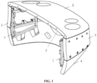
- FIGS. 1 to 6 Specific embodiments of a fixed hood according to the present application are described below with reference to FIGS. 1 to 6 .
- the fixed hood includes a mounting frame 1 and a fixed hood main body.
- the fixed hood main body is arranged outside the mounting frame and the mounting frame 1 is detachably connected to a vehicle body front-end bearing structure (not shown). As such, the fixed hood is assembled and fixed on the vehicle body.
- the fixed hood main body includes a top hood body 2, a bottom hood body 4 and two lateral hood bodies 3 which are separately arranged; and the top hood body 2, the bottom hood body 4 and the two lateral hood bodies 3 are detachably connected with the mounting frame 1 respectively.
- the two lateral hood bodies 3 are symmetrically arranged between the top hood body 2 and the bottom hood body 4, and the top hood body 2, the two lateral hood bodies 3 and the bottom hood body 4 are enclosed to form a front-end opening 5. That is, since the fixed hood main body is designed in a split structural arrangement, the fixed hood body is divided into four independent parts.
- the top hood body 2 is used to install components such as headlights and wipers, the lateral hood bodies 3 are used for daily disassembly and internal maintenance, and the bottom hood body 4 is used for fixing pipelines, wire racks and connecting a bottom obstacle remover.
- the fixed hood main body is designed in a modular structural arrangement, the fixed hood is not only easy to mount and adjust during the assembly of the fixed hood, but also quickly to be replaced without disassembling other external equipment when the fixed hood is damaged due to impact and cannot be repaired.
- damaged members in the fixed hood can be replaced separately without the need for overall replacement, which shortens the replacement cycle of the fixed hood, simplifies the process of replacing the fixed cover and decreases costs.
- the top hood body 2, the bottom hood body 4 and the two lateral hood bodies 3 are all molded, the same models and parts have good interchangeability, so that a damaged model or part can be replaced separately when the fixed hood is damaged. In this way, the assembled fixed hood has more precise overall profile.
- the mounting frame 1 includes a first frame and a second frame arranged symmetrically, and the first frame and the second frame both include a first support longitudinal bar 101, a second support longitudinal bar 102, a first connecting crossbar 103, a second connecting crossbar 104 and a third connecting crossbar 105.
- the first connecting crossbar 103, the second connecting crossbar 104 and the third connecting crossbar 105 are arranged along a height direction of the mounting frame 1 at intervals respectively, and both ends of the first connecting crossbar 103, both ends of the second connecting crossbar 104 and both ends of the third connecting crossbar 105 are connected with the first support longitudinal bar 101 and the second support longitudinal bar 102, respectively. That is, the connection between the first support longitudinal bar 101, the second support longitudinal bar 102, the first connecting crossbar 103, the second connecting crossbar 104 and the third connecting crossbar 105 can form a structurally stable truss structure.
- Both ends of the first connecting crossbar 103, both ends of the second connecting crossbar 104 and both ends of the third connecting crossbar 105 are all correspondingly welded with the first support longitudinal bar 101 and the second support longitudinal bar 102 to ensure the structural strength and reliability of the mounting frame 1.
- the first support longitudinal bar 101 is arranged close to the front-end opening 5, and the second support longitudinal bar 102 is arranged away from the front-end opening 5.
- the second support longitudinal bar 102 includes a plurality of the vehicle body mounting seats 6, and the plurality of the vehicle body mounting seats 6 are arranged along a length direction of the second support longitudinal bar 102 at intervals.
- Each of the vehicle body mounting seats 6 includes a first mounting portion 601 and a vehicle body connecting portion 602, the first mounting portion 601 and the vehicle body connecting portion 602 are connected to each other to form an L-shaped structure; the first mounting portion 601 is fixedly connected to the second support longitudinal bar 102, and the vehicle body connecting portion 602 is detachably connected to the vehicle body front-end bearing structure through a first connector (not shown in the figures). That is, by arranging the vehicle body mounting seats 6 on the mounting frame 1, reliable assembly and fixing between the mounting frame 1 and the vehicle body front-end bearing structure is implemented.
- the first connector may be bolts, screws or pins.
- the form of the first connector is not limited to the above-mentioned types.
- a plurality of first connecting plates 7 extending toward the top hood body 2 are fixedly arranged on the first connecting crossbar 103, and the plurality of first connecting plates 7 are arranged along a length direction of the first connecting crossbar 103 at intervals.
- Connecting folded edges 701 are arranged at an end of the plurality of first connecting plates 7 close to the top hood body 2.
- First pre-embedded bosses 21 being in one-to-one correspondence with each of the first connecting plates 7 are arranged inside the top hood body 2 and each of the first pre-embedded bosses 21 is detachably connected to each of the connecting folded edges 701 through a second connector (not shown).
- the detachable assembly and fixing between the mounting frame 1 and the top hood body 2 is implemented to facilitate the replacement operation of the top hood body 2.
- the second connector may be bolts, screws or pins.
- the form of the second connector is not limited to the above-mentioned types.
- a plurality of second connecting plates 8 extending toward the bottom hood body 4 are fixedly arranged on the third connecting crossbar 105, and the plurality of second connecting plates 8 are arranged along a length direction of the third connecting crossbar 105 at intervals.
- Second pre-embedded bosses 41 being in one-to-one correspondence with each of the second connecting plates 8 are arranged inside the bottom hood body 4 and each of the second pre-embedded bosses 41 is detachably connected to each of the second connecting plates 8 through a third connector (not shown).
- the detachable assembly and fixing between the mounting frame 1 and the bottom hood body 4 is implemented to facilitate the replacement operation of the bottom hood body 4.
- the third connector may be bolts, screws or pins.
- the form of the third connector is not limited to the above-mentioned types.
- a plurality of first connecting seats 9 are fixedly arranged on the first connecting crossbar 103, and the plurality of first connecting seats 9 are arranged along the length direction of the first connecting crossbar 103 at intervals, each of the first connecting seats 9 is a " ⁇ "-shaped structure protruding toward the direction of the lateral hood bodies 3, and each of the first connecting seats 9 is detachably connected to the lateral hood bodies 3 through a first adjusting connector.
- a plurality of second connecting seats 10 are fixedly arranged on the second connecting crossbar 104, and the plurality of second connecting seats 10 are arranged along a length direction of the second connecting crossbar 104 at intervals, each of the second connecting seats 10 is a " ⁇ "-shaped structure protruding toward the direction of the lateral hood bodies 3, and each of the second connecting seats 10 is detachably connected to the lateral hood bodies 3 through a second adjusting connector. That is, by arranging the first connecting seats 9 and second connecting seats 10 on the mounting frame 1, the detachable assembly and fixing between the mounting frame 1 and the lateral hood bodies 3 is implemented to facilitate the replacement operation of the lateral hood bodies 3.
- the first adjusting connector includes a first connecting screw (not shown in the figures) and a first floating nut 11 engaged with the first connecting screw, the first floating nut 11 is fixed inside the first connecting seat 9, the first connecting screw successively passes through the lateral hood bodies 3 and the first connecting seat 9 and is connected with the first floating nut 11.
- the second adjusting connector includes a second connecting screw (not shown in the figures) and a second floating nut 12 engaged with the second connecting screw, the second floating nut 12 is fixed inside the second connecting seat 10, the second connecting screw successively passes through the lateral hood bodies 3 and the second connecting seat 10 and is connected with the second floating nut 12.
- the positions of the top hood body 2, the bottom hood body 4 and each of the lateral hood bodies 3 can be effectively adjusted in the three-coordinate direction, and the final contour accuracy of the fixed hood is further improved on the basis of reducing grinding and assembling.
- the top hood body 2 is provided with top hood body flanges 201 corresponding to the lateral hood bodies 3, the lateral hood bodies 3 is provided with a first lateral hood body flange 301 engaged with the top hood body flange 201, and the first lateral hood body flange 301 and the top hood body flange 201 are spliced together to implement reliable assembly between the top hood body 2 and the lateral hood bodies 3.
- each of the top hood body flanges 201 is provided with a first limiting plate 202 for limiting a mounting position of each lateral hood body 3 and the first limiting plate 202 is arranged at a position on each top hood body flange 201 close to the front-end opening 5. That is, when the lateral hood bodies 3 are mounted on the top hood body 2, the mounting position of the lateral hood bodies 3 can be limited by the first limiting plate 202, and an assembly position between the lateral hood bodies 3 and the top hood body 2 is more quickly determined.
- a vehicle body connecting flange 203 is provided on a side of the top hood body 2 away from the front-end opening 5, the vehicle body connecting flange 203 includes a plurality of connecting holes 204 arranged along a length direction of the vehicle body connecting flange 203 at intervals and each of the connecting holes 204 is detachably connected to the vehicle body front-end bearing structure through a fourth connector (not shown). That is, by arranging the vehicle body connecting flange 203, it is convenient to assemble and fix the top hood body 2 and the vehicle body front-end bearing structure, and the assembly reliability between the fixed hood and the vehicle body is further improved.
- the fourth connector may be bolts, screws or pins.
- the form of the fourth connector is not limited to the above-mentioned types.
- the bottom hood body 4 is provided with bottom hood body flanges 401 corresponding to the lateral hood bodies 3, the lateral hood bodies 3 are provided with a second lateral hood body flange 302 engaged with the bottom hood body flange 401, and the second lateral hood body flange 302 and the bottom hood body flange 401 are spliced together to implement reliable assembly between the bottom hood body 4 and the lateral hood bodies 3.
- each of the bottom hood body flanges 401 is provided with a second limiting plate 402 for limiting a mounting position of each lateral hood body 3, and the second limiting plate 402 is arranged at a position on each bottom hood body flange 401 close to the front-end opening 5. That is, when the lateral hood bodies 3 are mounted on the bottom hood body 4, the mounting position of the lateral hood bodies 3 can be limited by the second limiting plate 402, and the assembly position of the lateral hood bodies 3 with respect to the bottom hood body 4 is more quickly determined.
- a limiting bayonet 303 corresponding to the second limiting plate 402 is arranged on the second lateral hood body flange 302, and the second limiting plate 402 can be snapped into in the limiting bayonet 303 when the lateral hood bodies 3 and the bottom hood body 4 are assembled, mounting positions of the lateral hood bodies 3 can be more quickly determined and the assembly efficiency is further improved.
- the installation process of the fixed hood of the embodiment of the present application at the new construction stage is as follows.
- the mounting frame 1 is connected to the vehicle body front-end bearing structure. Then the first pre-embedded bosses 21 on the top hood body 2 are connected with the first connecting plates 7 on the mounting frame 1, and then the vehicle body connecting flange 203 on the top hood body 2 is connected with the vehicle body front-end bearing structure.
- the second connecting plates 8 on the mounting frame 1 are connected through the second pre-embedded bosses 41 on the bottom hood body 4
- each lateral hood body 3 is buckled and mounted on the corresponding top hood body flange 201 and bottom hood body flange 401, and then the first connecting seats 9 and the second connecting seats 10 on the mounting frame 1 are fastened to the lateral hood bodies 3 respectively.
- the lateral hood bodies 3 can be taken off directly from the outside, the corresponding damaged parts are replaced, and the lateral hood bodies 3 is restored to its original state finally.
- the replaced parts can be installed directly after being sprayed in advance, and there is no need to disassemble other front-end parts. Therefore, by adopting the fixed hood according to the embodiment of the present application, the replacement cycle of the fixed hood can be effectively shortened and the replacement process of the fixed hood is simplified.
- An embodiment of the present application further provides a front hood, including a fixed hood and an opening and closing hood, where the fixed hood is the fixed hood according to the above embodiments. Since the front hood is provided with the fixed hood according to the above-mentioned embodiment, the front hood has all the advantages of the fixed hood according to the above-mentioned embodiment, thereby improving the performance of the hood.
- An embodiment of the present application further provides a rail vehicle, including the fixed hood according to the above embodiments, or the front hood according to the above embodiments. Since the rail vehicle is provided with the fixed hood according to the above embodiment or the front hood according to the above embodiment, the rail vehicle has all the advantages of the fixed hood according to the above embodiment or the front hood according to the above embodiment, thereby improving the use of the rail vehicle performance.
Landscapes
- Engineering & Computer Science (AREA)
- Mechanical Engineering (AREA)
- Life Sciences & Earth Sciences (AREA)
- Wood Science & Technology (AREA)
- Body Structure For Vehicles (AREA)
- Superstructure Of Vehicle (AREA)
Abstract
Description
- The present application claims priority to
Chinese application No. 202110655848.8 filed on June 11, 2021 - The present application relates to railway vehicle technologies, and in particular, to a fixed hood, a front hood and a railway vehicle.
- A front hood, as one of important components of a high-speed rail vehicle, has the following main functions: in case that the front hood is opened, operations such as coupler reconnection, emergency rescue and equipment maintenance can be performed on the rail vehicle; in case that the front hood is closed, the rail vehicle may have a streamlined shape during operation at a high speed, which decreases running resistance and improves safety and stability. The front hood generally is consisted of two parts: a fixed hood being stationary relative to the vehicle and an opening and closing hood moving relative to the vehicle.
- During high-speed operation, a rail train is easily subjected to impacts from foreign objects such as gravel, stones and birds. The front hood is impacted and damaged severely because of locating at the front end of the train. In case that the opening and closing hood cannot be used due to severe damage, functions of the front hood can be quickly restored by replacing it with a new front hood. The fixed hood is connected to the vehicle body through fasteners, which has a huge overall volume. When the front hood is replaced, much external equipment such as couplers, obstacle removers, and opening or closing mechanisms need to be removed. After the front hood is replaced, the external equipment needs to be restored one by one and the entire vehicle is painted and repaired together with the front, which makes overall replacement process being time-consuming and complicated. Therefore, a mounting structure of a traditional fixed hood cannot meet the requirements of a high-speed train.
- The present application provides a fixed hood, which can be quickly replaced under the premise of avoiding the removal of other external devices.
- An embodiment of the present application provides a fixed hood, including:
- a mounting frame, configured to be detachably connected to a vehicle body front-end bearing structure; and
- a fixed hood main body, arranged outside the mounting frame and including a top hood body, a bottom hood body and two lateral hood bodies, where the top hood body, the bottom hood body and the two lateral hood bodies are detachably connected to the mounting frame respectively, the two lateral hood bodies are symmetrically arranged between the top hood body and the bottom hood body, to make the top hood body, the bottom hood body and the two lateral hood bodies enclose to form a front-end opening.
- In the fixed hood according to an embodiment of the present application, the mounting frame includes a first frame and a second frame arranged symmetrically, and each of the first frame and the second frame includes a first support longitudinal bar, a second support longitudinal bar, a first connecting crossbar, a second connecting crossbar and a third connecting crossbar, the first connecting crossbar, the second connecting crossbar and the third connecting crossbar are arranged along a height direction of the mounting frame at intervals, and both ends of the first connecting crossbar, both ends of the second connecting crossbar and both ends of the third connecting crossbar are connected with the first support longitudinal bar and the second support longitudinal bar respectively.
- In the fixed hood according to an embodiment of the present application, the first support longitudinal bar is arranged close to the front-end opening, and the second support longitudinal bar is arranged far away from the front-end opening; a plurality of the vehicle body mounting seats are arranged along a length direction of the second support longitudinal bar at intervals, each of the plurality of the vehicle body mounting seats includes a first mounting portion and a vehicle body connecting portion, the first mounting portion and the vehicle body connecting portion are connected to each other to form an L-shaped structure; the first mounting portion is fixedly connected to the second support longitudinal bar, and the vehicle body connecting portion is detachably connected to the vehicle body front-end bearing structure through a first connector.
- In the fixed hood according to an embodiment of the present application, a plurality of first connecting plates extending toward the top hood body are fixedly arranged on the first connecting crossbar, and the plurality of first connecting plates are arranged along a length direction of the first connecting crossbar at intervals; connecting folded edges are arranged at an end of each of the plurality of first connecting plates close to the top hood body; first pre-embedded bosses being in one-to-one correspondence with the plurality of the first connecting plates are arranged inside the top hood body, and each of the first pre-embedded bosses is detachably connected to each of the connecting folded edges through a second connector.
- In the fixed hood according to an embodiment of the present application, a plurality of second connecting plates extending toward the top hood body are fixedly arranged on the third connecting crossbar, and the plurality of second connecting plates are arranged along a length direction of the third connecting crossbar at intervals; second pre-embedded bosses being in one-to-one correspondence with the plurality of second connecting plates are arranged inside the bottom hood body, and each of the second pre-embedded bosses is detachably connected to each of the plurality of second connecting plates through a third connector.
- In the fixed hood according to an embodiment of the present application, a plurality of first connecting seats are fixedly arranged on the first connecting crossbar, and the plurality of first connecting seats are arranged along the length direction of the first connecting crossbar at intervals, each of the first connecting seats is a "π"-shaped structure protruding toward the direction of the lateral hood bodies, and each of the first connecting seats is detachably connected to the lateral hood bodies through a first adjusting connector; and
a plurality of second connecting seats are fixedly arranged on the second connecting crossbar, and the plurality of second connecting seats are arranged along a length direction of the second connecting crossbar at intervals, each of the second connecting seats is a "π"-shaped structure protruding toward the direction of the lateral hood bodies, and each of the second connecting seats is detachably connected to the lateral hood body through a second adjusting connector. - In the fixed hood according to an embodiment of the present application, the first adjusting connector includes a first connecting screw and a first floating nut engaged with the first connecting screw, the first floating nut is fixed inside the first connecting seat, the first connecting screw successively passes through the lateral hood bodies, and the first connecting seat and is connected with the first floating nut; and
the second adjusting connector includes a second connecting screw and a second floating nut engaged with the second connecting screw, the second floating nut is fixed inside the second connecting seat, the second connecting screw successively passes through both the lateral hood bodies, and the second connecting seat and is connected with the second floating nut. - In the fixed hood according to an embodiment of the present application, the top hood body is provided with top hood body flanges corresponding to the lateral hood bodies, the lateral hood bodies are provided with a first lateral hood body flange engaged with the top hood body flange, and the first lateral hood body flange and the top hood body flange are spliced together.
- In the fixed hood according to an embodiment of the present application, each of the top hood body flanges is provided with a first limiting plate for limiting a mounting position of each lateral hood body, and the first limiting plate is arranged at a position on each top hood body flange close to the front-end opening.
- In the fixed hood according to an embodiment of the present application, a vehicle body connecting flange is provided on a side of the top hood body away from the front-end opening, the vehicle body connecting flange includes a plurality of connecting holes arranged along a length direction of the vehicle body connecting flange at intervals, and each of the plurality of connecting holes is detachably connected to the vehicle body front-end bearing structure through a fourth connector.
- In the fixed hood according to an embodiment of the present application, the bottom hood body is provided with bottom hood body flanges corresponding to the lateral hood bodies, and each of the lateral hood bodies is provided with a second lateral hood body flange engaged with the bottom hood body, and the second lateral hood body flange and the bottom hood body flange are spliced together.
- In the fixed hood according to an embodiment of the present application, each of the bottom hood body flanges is provided with a second limiting plate for limiting a mounting position of each lateral hood body, and the second limiting plate is arranged at a position on each bottom hood body flange close to the front-end opening.
- In the fixed hood according to an embodiment of the present application, a limiting bayonet corresponding to the second limiting plate is arranged on the second lateral hood body flange, and the second limiting plate is snapped into in the limiting bayonet.
- An embodiment of the present application further provides a front hood, including the fixed hood according to the above embodiments.
- An embodiment of the present application further provides a rail vehicle, including the fixed hood according to the above embodiments, or the front hood according to the above embodiments.
- One or more solutions in the embodiments of the present application mentioned above have at least one of the following effects.
- The fixed hood according to the embodiment of the present application includes the mounting frame and the fixed hood main body, the mounting frame is provided to be detachably connected to a vehicle body front-end bearing structure; and the fixed hood main body is arranged outside the mounting frame and including a top hood body, a bottom hood body and two lateral hood bodies, where the top hood body, the bottom hood body and the two lateral hood bodies are detachably connected to the mounting frame, respectively, the two lateral hood bodies are symmetrically arranged between the top hood body and the bottom hood body, and the top hood body, to make the bottom hood body and the two lateral hood bodies are enclosed to form a front-end opening. Since the fixed hood main body is designed in a split structural arrangement, the fixed hood is not only easy to mount and adjust during the assembly of the fixed hood, but also quickly to be replaced when the fixed hood is damaged due to impact and cannot be repaired. In addition, damaged members in the fixed hood can be replaced separately without overall replacement, which not only shortens the replacement cycle of the fixed hood and decreases costs.
- The front hood according to an embodiment of the present application includes the fixed hood according to the above embodiments. Since the front hood is provided with the fixed hood according to the above-mentioned embodiment, the front hood has all the advantages of the fixed hood according to the above-mentioned embodiment, thereby improving the performance of the hood.
- A rail vehicle according to an embodiment of the present application includes the fixed hood according to the above embodiments or the front hood according to the above embodiments. Since the rail vehicle is provided with the fixed hood according to the above embodiment or the front hood according to the above embodiment, the rail vehicle has all the advantages of the fixed hood according to the above embodiment or the front hood according to the above embodiment, thereby improving the use of the rail vehicle performance.
- Additional aspects and advantages of this application will be partially given in the following description, and some thereof will become obvious from the following description, or be understood through the practice of this application.
- In order to clearly illustrate the solutions according to the present application or the related art, the accompanying drawings used in the description of the embodiments of the present application or the related art are briefly introduced below. It should be noted that the drawings in the following description are only part embodiments of the present application. For those of ordinary skill in the art, other drawings can be obtained according to these drawings without creative efforts.
-
FIG. 1 is a schematic structural diagram of a fixed hood according to the present application; -
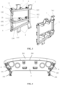
FIG. 2 is an assembly schematic diagram of a fixed hood after lateral hood bodies are removed according to the present application; -
FIG. 3 is a schematic structural diagram of a mounting framework according to the present application; -
FIG. 4 is a schematic structural diagram of a top hood body according to the present application; -
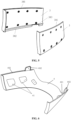
FIG. 5 is a schematic structural diagram of two lateral hood bodies according to the present application; and -
FIG. 6 is a schematic structural diagram of a bottom hood body according to the present application. -
- 1: mounting frame; 101: first support longitudinal bar; 102: second support longitudinal bar;
- 103: first connecting crossbar; 104: second connecting crossbar; 105: third connecting crossbar;
- 2: top hood body; 21: first pre-embedded boss; 201: top hood body flange;
- 202: first limiting plate; 203: vehicle body connecting flange; 204: connecting hole;
- 3: lateral hood body; 301: first lateral hood body flange;
- 302: second lateral hood body flange; 303: limiting bayonet; 4: bottom hood body;
- 41: second pre-embedded boss; 401: bottom hood body flange; 402: second limiting plate;
- 5: front-end opening;
- 6: vehicle body mounting seat; 601: first mounting portion; 602: vehicle body connecting portion;
- 7: first connecting plate; 701: connecting folded edge; 8: second connecting plate;
- 9: first connecting seat; 10: second connecting seat; 11: first floating nut;
- 12: second floating nut.
- Embodiments of the present application are further described in detail below with reference to the drawings and embodiments. The following embodiments are intended to illustrate the application, but are not intended to limit the scope of the application.
- In the description of the embodiments of the present application, it is to be noted that the orientation or positional relationships indicated by terms such as "center", "longitudinal", "lateral", "upper", "lower", "front", "rear", "left", "right", "vertical", "horizontal", "top", "bottom", "inside", "outside", etc. are based on the orientation or positional relationship shown in the drawings, and are merely for the convenience of describing the embodiments of the present application and simplifying the description, rather than indicating or implying that the device or component stated must have a particular orientation, is constructed and operated in a particular orientation, and thus is not to be construed as limiting the embodiments of the present application. Moreover, the terms "first", "second", "third", and the like are used for descriptive purposes only and are not to be construed as indicating or implying relative importance.
- In the description of the embodiments of the present application, it is to be noted that unless explicitly stated and defined otherwise, the terms "connected with," and "connected" shall be understood broadly, for example, it may be either fixedly connected or detachably connected, or can be integrated; it may be mechanically connected, or electrically connected; it may be directly connected, or indirectly connected through an intermediate medium. The specific meanings of the terms above in embodiments of the present application can be understood by a person skilled in the art in accordance with specific conditions.
- In the embodiments of this application, unless otherwise clearly stated and defined, the first feature being located "on" or "under" the second feature means that the first feature is in direct contact with the second feature or the first feature is in contact with the second feature by an intervening media. Also, the first feature being located "on", "above" and "on top of' the second feature may mean that the first feature is directly on or above the second feature, or it simply means that the level of the first feature is higher than the second feature. The first feature being located "under", "below" and "on bottom of" the second feature may mean that the first feature is directly under or below the second feature, or it simply means that the level of the first feature is lower than the second feature.
- In the description of this specification, descriptions with reference to the terms "one embodiment", "some embodiments", "examples", "specific examples", or "some examples" etc. mean that specific features, structure, materials or characteristics described in conjunction with the embodiment or example are included in at least one embodiment or example of the embodiments of the present application. In this specification, the schematic expressions of the above terms do not necessarily refer to the same embodiment or example. Also, the described specific features, structures, materials or characteristics can be combined in any one or more embodiments or examples in a suitable manner. In addition, those skilled in the art may integrate and combine the different embodiments or examples and the features of the different embodiments or examples described in this specification without contradicting each other.
- Specific embodiments of a fixed hood according to the present application are described below with reference to
FIGS. 1 to 6 . - The fixed hood according to the present application includes a mounting
frame 1 and a fixed hood main body. The fixed hood main body is arranged outside the mounting frame and the mountingframe 1 is detachably connected to a vehicle body front-end bearing structure (not shown). As such, the fixed hood is assembled and fixed on the vehicle body. - The fixed hood main body includes a
top hood body 2, abottom hood body 4 and twolateral hood bodies 3 which are separately arranged; and thetop hood body 2, thebottom hood body 4 and the twolateral hood bodies 3 are detachably connected with the mountingframe 1 respectively. The twolateral hood bodies 3 are symmetrically arranged between thetop hood body 2 and thebottom hood body 4, and thetop hood body 2, the twolateral hood bodies 3 and thebottom hood body 4 are enclosed to form a front-end opening 5. That is, since the fixed hood main body is designed in a split structural arrangement, the fixed hood body is divided into four independent parts. Thetop hood body 2 is used to install components such as headlights and wipers, thelateral hood bodies 3 are used for daily disassembly and internal maintenance, and thebottom hood body 4 is used for fixing pipelines, wire racks and connecting a bottom obstacle remover. - In the fixed hood according to the embodiment of the present application, since the fixed hood main body is designed in a modular structural arrangement, the fixed hood is not only easy to mount and adjust during the assembly of the fixed hood, but also quickly to be replaced without disassembling other external equipment when the fixed hood is damaged due to impact and cannot be repaired. In addition, damaged members in the fixed hood can be replaced separately without the need for overall replacement, which shortens the replacement cycle of the fixed hood, simplifies the process of replacing the fixed cover and decreases costs.
- In an embodiment, the
top hood body 2, thebottom hood body 4 and the twolateral hood bodies 3 are all molded, the same models and parts have good interchangeability, so that a damaged model or part can be replaced separately when the fixed hood is damaged. In this way, the assembled fixed hood has more precise overall profile. - In an embodiment of the present application, the mounting
frame 1 includes a first frame and a second frame arranged symmetrically, and the first frame and the second frame both include a first supportlongitudinal bar 101, a second supportlongitudinal bar 102, a first connectingcrossbar 103, a second connectingcrossbar 104 and a third connectingcrossbar 105. The first connectingcrossbar 103, the second connectingcrossbar 104 and the third connectingcrossbar 105 are arranged along a height direction of the mountingframe 1 at intervals respectively, and both ends of the first connectingcrossbar 103, both ends of the second connectingcrossbar 104 and both ends of the third connectingcrossbar 105 are connected with the first supportlongitudinal bar 101 and the second supportlongitudinal bar 102, respectively. That is, the connection between the first supportlongitudinal bar 101, the second supportlongitudinal bar 102, the first connectingcrossbar 103, the second connectingcrossbar 104 and the third connectingcrossbar 105 can form a structurally stable truss structure. - Both ends of the first connecting
crossbar 103, both ends of the second connectingcrossbar 104 and both ends of the third connectingcrossbar 105 are all correspondingly welded with the first supportlongitudinal bar 101 and the second supportlongitudinal bar 102 to ensure the structural strength and reliability of the mountingframe 1. - In an embodiment of the present application, the first support
longitudinal bar 101 is arranged close to the front-end opening 5, and the second supportlongitudinal bar 102 is arranged away from the front-end opening 5. The second supportlongitudinal bar 102 includes a plurality of the vehiclebody mounting seats 6, and the plurality of the vehiclebody mounting seats 6 are arranged along a length direction of the second supportlongitudinal bar 102 at intervals. Each of the vehiclebody mounting seats 6 includes a first mountingportion 601 and a vehiclebody connecting portion 602, the first mountingportion 601 and the vehiclebody connecting portion 602 are connected to each other to form an L-shaped structure; the first mountingportion 601 is fixedly connected to the second supportlongitudinal bar 102, and the vehiclebody connecting portion 602 is detachably connected to the vehicle body front-end bearing structure through a first connector (not shown in the figures). That is, by arranging the vehiclebody mounting seats 6 on the mountingframe 1, reliable assembly and fixing between the mountingframe 1 and the vehicle body front-end bearing structure is implemented. - According to actual usage requirements, the first connector may be bolts, screws or pins. The form of the first connector is not limited to the above-mentioned types.
- In an embodiment of the present application, a plurality of first connecting
plates 7 extending toward thetop hood body 2 are fixedly arranged on the first connectingcrossbar 103, and the plurality of first connectingplates 7 are arranged along a length direction of the first connectingcrossbar 103 at intervals. Connecting foldededges 701 are arranged at an end of the plurality of first connectingplates 7 close to thetop hood body 2. Firstpre-embedded bosses 21 being in one-to-one correspondence with each of the first connectingplates 7 are arranged inside thetop hood body 2 and each of the firstpre-embedded bosses 21 is detachably connected to each of the connecting foldededges 701 through a second connector (not shown). That is, by arranging the first connectingplates 7 on the mountingframe 1 and arranging the firstpre-embedded boss 21 on thetop hood body 2, the detachable assembly and fixing between the mountingframe 1 and thetop hood body 2 is implemented to facilitate the replacement operation of thetop hood body 2. - According to actual usage requirements, the second connector may be bolts, screws or pins. The form of the second connector is not limited to the above-mentioned types.
- In an embodiment of the present application, a plurality of second connecting
plates 8 extending toward thebottom hood body 4 are fixedly arranged on the third connectingcrossbar 105, and the plurality of second connectingplates 8 are arranged along a length direction of the third connectingcrossbar 105 at intervals. Secondpre-embedded bosses 41 being in one-to-one correspondence with each of the second connectingplates 8 are arranged inside thebottom hood body 4 and each of the secondpre-embedded bosses 41 is detachably connected to each of the second connectingplates 8 through a third connector (not shown). That is, by arranging the second connectingplates 8 on the mountingframe 1 and arranging the secondpre-embedded boss 41 on thebottom hood body 4, the detachable assembly and fixing between the mountingframe 1 and thebottom hood body 4 is implemented to facilitate the replacement operation of thebottom hood body 4. - According to actual usage requirements, the third connector may be bolts, screws or pins. The form of the third connector is not limited to the above-mentioned types.
- In an embodiment of the present application, a plurality of first connecting
seats 9 are fixedly arranged on the first connectingcrossbar 103, and the plurality of first connectingseats 9 are arranged along the length direction of the first connectingcrossbar 103 at intervals, each of the first connectingseats 9 is a "π"-shaped structure protruding toward the direction of thelateral hood bodies 3, and each of the first connectingseats 9 is detachably connected to thelateral hood bodies 3 through a first adjusting connector. A plurality of second connectingseats 10 are fixedly arranged on the second connectingcrossbar 104, and the plurality of second connectingseats 10 are arranged along a length direction of the second connectingcrossbar 104 at intervals, each of the second connectingseats 10 is a "π"-shaped structure protruding toward the direction of thelateral hood bodies 3, and each of the second connectingseats 10 is detachably connected to thelateral hood bodies 3 through a second adjusting connector. That is, by arranging the first connectingseats 9 and second connectingseats 10 on the mountingframe 1, the detachable assembly and fixing between the mountingframe 1 and thelateral hood bodies 3 is implemented to facilitate the replacement operation of thelateral hood bodies 3. - In an embodiment, the first adjusting connector includes a first connecting screw (not shown in the figures) and a first floating
nut 11 engaged with the first connecting screw, the first floatingnut 11 is fixed inside the first connectingseat 9, the first connecting screw successively passes through thelateral hood bodies 3 and the first connectingseat 9 and is connected with the first floatingnut 11. Through the assembly adjustment of the first floatingnut 11 and the first connecting screw rod, errors can be adjusted during the installation process. - In an embodiment, the second adjusting connector includes a second connecting screw (not shown in the figures) and a second floating
nut 12 engaged with the second connecting screw, the second floatingnut 12 is fixed inside the second connectingseat 10, the second connecting screw successively passes through thelateral hood bodies 3 and the second connectingseat 10 and is connected with the second floatingnut 12. Through the assembly adjustment of the second floatingnut 12 and the second connecting screw rod, errors can be adjusted during the installation process. - Therefore, by arranging the first adjusting connector and the second adjusting connector, the positions of the
top hood body 2, thebottom hood body 4 and each of thelateral hood bodies 3 can be effectively adjusted in the three-coordinate direction, and the final contour accuracy of the fixed hood is further improved on the basis of reducing grinding and assembling. - In an embodiment of the present application, the
top hood body 2 is provided with tophood body flanges 201 corresponding to thelateral hood bodies 3, thelateral hood bodies 3 is provided with a first lateralhood body flange 301 engaged with the tophood body flange 201, and the first lateralhood body flange 301 and the tophood body flange 201 are spliced together to implement reliable assembly between thetop hood body 2 and thelateral hood bodies 3. - In an embodiment of the present application, each of the top
hood body flanges 201 is provided with a first limitingplate 202 for limiting a mounting position of eachlateral hood body 3 and the first limitingplate 202 is arranged at a position on each tophood body flange 201 close to the front-end opening 5. That is, when thelateral hood bodies 3 are mounted on thetop hood body 2, the mounting position of thelateral hood bodies 3 can be limited by the first limitingplate 202, and an assembly position between thelateral hood bodies 3 and thetop hood body 2 is more quickly determined. - In an embodiment of the present application, a vehicle
body connecting flange 203 is provided on a side of thetop hood body 2 away from the front-end opening 5, the vehiclebody connecting flange 203 includes a plurality of connectingholes 204 arranged along a length direction of the vehiclebody connecting flange 203 at intervals and each of the connectingholes 204 is detachably connected to the vehicle body front-end bearing structure through a fourth connector (not shown). That is, by arranging the vehiclebody connecting flange 203, it is convenient to assemble and fix thetop hood body 2 and the vehicle body front-end bearing structure, and the assembly reliability between the fixed hood and the vehicle body is further improved. - According to actual usage requirements, the fourth connector may be bolts, screws or pins. The form of the fourth connector is not limited to the above-mentioned types.
- In an embodiment of the present application, the
bottom hood body 4 is provided with bottomhood body flanges 401 corresponding to thelateral hood bodies 3, thelateral hood bodies 3 are provided with a second lateralhood body flange 302 engaged with the bottomhood body flange 401, and the second lateralhood body flange 302 and the bottomhood body flange 401 are spliced together to implement reliable assembly between thebottom hood body 4 and thelateral hood bodies 3. - In an embodiment of the present application, each of the bottom
hood body flanges 401 is provided with a second limitingplate 402 for limiting a mounting position of eachlateral hood body 3, and the second limitingplate 402 is arranged at a position on each bottomhood body flange 401 close to the front-end opening 5. That is, when thelateral hood bodies 3 are mounted on thebottom hood body 4, the mounting position of thelateral hood bodies 3 can be limited by the second limitingplate 402, and the assembly position of thelateral hood bodies 3 with respect to thebottom hood body 4 is more quickly determined. - In an embodiment of the present application, a limiting
bayonet 303 corresponding to the second limitingplate 402 is arranged on the second lateralhood body flange 302, and the second limitingplate 402 can be snapped into in the limitingbayonet 303 when thelateral hood bodies 3 and thebottom hood body 4 are assembled, mounting positions of thelateral hood bodies 3 can be more quickly determined and the assembly efficiency is further improved. - The installation process of the fixed hood of the embodiment of the present application at the new construction stage is as follows.
- Firstly, the mounting
frame 1 is connected to the vehicle body front-end bearing structure. Then the firstpre-embedded bosses 21 on thetop hood body 2 are connected with the first connectingplates 7 on the mountingframe 1, and then the vehiclebody connecting flange 203 on thetop hood body 2 is connected with the vehicle body front-end bearing structure. - Secondly, the second connecting
plates 8 on the mountingframe 1 are connected through the secondpre-embedded bosses 41 on thebottom hood body 4 - Finally, each
lateral hood body 3 is buckled and mounted on the corresponding tophood body flange 201 and bottomhood body flange 401, and then the first connectingseats 9 and the second connectingseats 10 on the mountingframe 1 are fastened to thelateral hood bodies 3 respectively. - When the fixed hood of the rail vehicle needs to be replaced due to impact or foreign matter hitting, the
lateral hood bodies 3 can be taken off directly from the outside, the corresponding damaged parts are replaced, and thelateral hood bodies 3 is restored to its original state finally. The replaced parts can be installed directly after being sprayed in advance, and there is no need to disassemble other front-end parts. Therefore, by adopting the fixed hood according to the embodiment of the present application, the replacement cycle of the fixed hood can be effectively shortened and the replacement process of the fixed hood is simplified. - An embodiment of the present application further provides a front hood, including a fixed hood and an opening and closing hood, where the fixed hood is the fixed hood according to the above embodiments. Since the front hood is provided with the fixed hood according to the above-mentioned embodiment, the front hood has all the advantages of the fixed hood according to the above-mentioned embodiment, thereby improving the performance of the hood.
- An embodiment of the present application further provides a rail vehicle, including the fixed hood according to the above embodiments, or the front hood according to the above embodiments. Since the rail vehicle is provided with the fixed hood according to the above embodiment or the front hood according to the above embodiment, the rail vehicle has all the advantages of the fixed hood according to the above embodiment or the front hood according to the above embodiment, thereby improving the use of the rail vehicle performance.
- Finally, it should be noted that the above embodiments are only used to explain the technical solutions of the present application, and are not limited thereto; although the present application has been described in detail with reference to the foregoing embodiments, it should be understood by those skilled in the art that they can still modify the solutions documented in the foregoing embodiments and make equivalent substitutions to a part of the technical features; these modifications and substitutions do not make the essence of the corresponding technical solutions depart from the spirit and scope of the solutions of various embodiments of the present application.
Claims (15)
- A fixed hood, comprising:a mounting frame, configured to be detachably connected to a vehicle body front-end bearing structure; anda fixed hood main body, arranged outside the mounting frame and comprising a top hood body, a bottom hood body and two lateral hood bodies, wherein the top hood body, the bottom hood body and the two lateral hood bodies are detachably connected to the mounting frame respectively, the two lateral hood bodies are symmetrically arranged between the top hood body and the bottom hood body, to make the top hood body, the bottom hood body and the two lateral hood bodies enclose to form a front-end opening.
- The fixed hood of claim 1, wherein the mounting frame comprises a first frame and a second frame arranged symmetrically, each of the first frame and the second frame comprises a first support longitudinal bar, a second support longitudinal bar, a first connecting crossbar, a second connecting crossbar and a third connecting crossbar, the first connecting crossbar, the second connecting crossbar and the third connecting crossbar are arranged along a height direction of the mounting frame at intervals, and both ends of the first connecting crossbar, both ends of the second connecting crossbar and both ends of the third connecting crossbar are connected with the first support longitudinal bar and the second support longitudinal bar respectively.
- The fixed hood of claim 2, wherein the first support longitudinal bar is arranged close to the front-end opening, and the second support longitudinal bar is arranged far away from the front-end opening; a plurality of the vehicle body mounting seats are arranged along a length direction of the second support longitudinal bar at intervals, each of the plurality of the vehicle body mounting seats comprises a first mounting portion and a vehicle body connecting portion, the first mounting portion and the vehicle body connecting portion are connected to each other to form an L-shaped structure; the first mounting portion is fixedly connected to the second support longitudinal bar, and the vehicle body connecting portion is detachably connected to the vehicle body front-end bearing structure through a first connector.
- The fixed hood of claim 2, wherein a plurality of first connecting plates extending toward the top hood body are fixedly arranged on the first connecting crossbar, and the plurality of first connecting plates are arranged along a length direction of the first connecting crossbar at intervals; connecting folded edges are arranged at an end of each of the plurality of first connecting plates close to the top hood body; first pre-embedded bosses being in one-to-one correspondence with the plurality of the first connecting plates are arranged inside the top hood body, and each of the first pre-embedded bosses is detachably connected to each of the connecting folded edges through a second connector.
- The fixed hood of claim 2, wherein a plurality of second connecting plates extending toward the top hood body are fixedly arranged on the third connecting crossbar, and the plurality of second connecting plates are arranged along a length direction of the third connecting crossbar at intervals; second pre-embedded bosses being in one-to-one correspondence with the plurality of second connecting plates are arranged inside the bottom hood body, and each of the second pre-embedded bosses is detachably connected to each of the plurality of second connecting plates through a third connector.
- The fixed hood of claim 2, wherein a plurality of first connecting seats are fixedly arranged on the first connecting crossbar, and the plurality of first connecting seats are arranged along a length direction of the first connecting crossbar at intervals, each of the first connecting seats is a "π"-shaped structure protruding toward the direction of the lateral hood bodies, and each of the first connecting seats is detachably connected to the lateral hood bodies through a first adjusting connector; and
a plurality of second connecting seats are fixedly arranged on the second connecting crossbar, and the plurality of second connecting seats are arranged along a length direction of the second connecting crossbar at intervals, each of the second connecting seats is a "π"-shaped structure protruding toward the direction of the lateral hood bodies, and each of the second connecting seats is detachably connected to the lateral hood body through a second adjusting connector. - The fixed hood of claim 6, wherein the first adjusting connector comprises a first connecting screw and a first floating nut engaged with the first connecting screw, the first floating nut is fixed inside the first connecting seat, the first connecting screw successively passes through the lateral hood bodies, and the first connecting seat and is connected with the first floating nut; and
the second adjusting connector comprises a second connecting screw and a second floating nut engaged with the second connecting screw, the second floating nut is fixed inside the second connecting seat, the second connecting screw successively passes through the lateral hood bodies, and the second connecting seat and is connected with the second floating nut. - The fixed hood of any one of claims 1 to 7, wherein the top hood body is provided with top hood body flanges corresponding to the lateral hood bodies, the lateral hood bodies are provided with a first lateral hood body flange fit with the top hood body, and the first lateral hood body flange and the top hood body flange are spliced together.
- The fixed hood of claim 8, wherein each of the top hood body flanges is provided with a first limiting plate for limiting a mounting position of each lateral hood body, and the first limiting plate is arranged at a position on each top hood body flange close to the front-end opening.
- The fixed hood of any one of claims 1 to 7, wherein a vehicle body connecting flange is provided on a side of the top hood body away from the front-end opening, the vehicle body connecting flange comprises a plurality of connecting holes arranged along a length direction of the vehicle body connecting flange at intervals, and each of the plurality of connecting holes is detachably connected to the vehicle body front-end bearing structure through a fourth connector.
- The fixed hood of any one of claims 1 to 7, wherein the bottom hood body is provided with bottom hood body flanges corresponding to the lateral hood bodies, and each of the lateral hood bodies is provided with a second lateral hood body flange engaged with the bottom hood body, and the second lateral hood body flange and the bottom hood body flange are spliced together.
- The fixed hood of claim 11, wherein each of the bottom hood body flanges is provided with a second limiting plate for limiting a mounting position of each lateral hood body, and the second limiting plate is arranged at a position on each bottom hood body flange close to the front-end opening.
- The fixed hood of claim 12, wherein a limiting bayonet corresponding to the second limiting plate is arranged on the second lateral hood body flange, and the second limiting plate is snapped into in the limiting bayonet.
- A front hood, comprising the fixed hood of any one of claims 1 to 13.
- A rail vehicle, comprising the fixed hood of any one of claims 1 to 13, or the front hood of claim 14.
Applications Claiming Priority (2)
| Application Number | Priority Date | Filing Date | Title |
|---|---|---|---|
| CN202110655848.8A CN113306581B (en) | 2021-06-11 | 2021-06-11 | Fixed cover, hood and rail vehicle |
| PCT/CN2021/135117 WO2022257380A1 (en) | 2021-06-11 | 2021-12-02 | Fixed cover, front cover, and rail vehicle |
Publications (3)
| Publication Number | Publication Date |
|---|---|
| EP4269207A1 true EP4269207A1 (en) | 2023-11-01 |
| EP4269207A4 EP4269207A4 (en) | 2024-07-31 |
| EP4269207B1 EP4269207B1 (en) | 2026-04-08 |
Family
ID=77378652
Family Applications (1)
| Application Number | Title | Priority Date | Filing Date |
|---|---|---|---|
| EP21944876.8A Active EP4269207B1 (en) | 2021-06-11 | 2021-12-02 | Fixed cover, front cover, and rail vehicle |
Country Status (3)
| Country | Link |
|---|---|
| EP (1) | EP4269207B1 (en) |
| CN (1) | CN113306581B (en) |
| WO (1) | WO2022257380A1 (en) |
Families Citing this family (2)
| Publication number | Priority date | Publication date | Assignee | Title |
|---|---|---|---|---|
| CN113306581B (en) * | 2021-06-11 | 2022-11-22 | 中车青岛四方机车车辆股份有限公司 | Fixed cover, hood and rail vehicle |
| CN114394117B (en) * | 2022-01-20 | 2023-05-23 | 中车青岛四方机车车辆股份有限公司 | Cab structure of railway vehicle and railway vehicle |
Family Cites Families (17)
| Publication number | Priority date | Publication date | Assignee | Title |
|---|---|---|---|---|
| GB349349A (en) * | 1930-06-28 | 1931-05-28 | Herbert Austin | Improvements in, or relating to, hoods or head coverings for motor vehicles |
| JPH0629023B2 (en) * | 1988-05-06 | 1994-04-20 | 豊三郎 三上 | Manufacturing method of connecting hood for vehicle |
| CN103802848B (en) * | 2012-11-08 | 2016-12-21 | 中车青岛四方机车车辆股份有限公司 | The hood structure of bullet train headstock and installation method |
| CN103625483B (en) * | 2013-10-25 | 2016-05-25 | 中车青岛四方机车车辆股份有限公司 | Railway vehicle cab front end fixed cover and manufacture method thereof |
| CN203592984U (en) * | 2013-11-08 | 2014-05-14 | 青岛罗美威奥新材料制造有限公司 | Rail train integrated train head structure |
| CN105799811B (en) * | 2014-12-08 | 2018-09-21 | 奇瑞汽车股份有限公司 | A kind of hood harness and the installation method using the harness |
| JP6615598B2 (en) * | 2015-12-16 | 2019-12-04 | 日本車輌製造株式会社 | High speed train |
| DE102016205305A1 (en) * | 2016-03-31 | 2017-10-05 | Siemens Aktiengesellschaft | Rail vehicle, in particular locomotive |
| CN207416843U (en) * | 2017-10-13 | 2018-05-29 | 青岛罗美威奥新材料制造有限公司 | The front end of a kind of high ferro and EMU is opened and closed outer cover |
| CN207416842U (en) * | 2017-11-03 | 2018-05-29 | 成都市新筑路桥机械股份有限公司 | A kind of 100% low-floor urban tram dual layer hood structure |
| DE102018109236A1 (en) * | 2018-04-18 | 2019-10-24 | Bombardier Transportation Gmbh | Front hood for a rail vehicle car, method for assembling at least one front hood and rail vehicle car with at least one front hood |
| CN110027577B (en) * | 2019-04-17 | 2020-06-02 | 中车青岛四方机车车辆股份有限公司 | Aluminum honeycomb and aluminum plate splicing cab and railway vehicle with same |
| CN210416557U (en) * | 2019-08-15 | 2020-04-28 | 中车株洲电力机车有限公司 | All-aluminum alloy cab structure |
| CN211893211U (en) * | 2020-01-22 | 2020-11-10 | 中车青岛四方车辆研究所有限公司 | Opening and closing mechanism |
| CN212709389U (en) * | 2020-05-21 | 2021-03-16 | 北京天亿万赛轻量化材料有限公司 | Cab hood structure and rail vehicle |
| CN112298227B (en) * | 2020-11-05 | 2022-02-15 | 中车青岛四方机车车辆股份有限公司 | Modular cab structure and rail vehicle |
| CN113306581B (en) * | 2021-06-11 | 2022-11-22 | 中车青岛四方机车车辆股份有限公司 | Fixed cover, hood and rail vehicle |
-
2021
- 2021-06-11 CN CN202110655848.8A patent/CN113306581B/en active Active
- 2021-12-02 EP EP21944876.8A patent/EP4269207B1/en active Active
- 2021-12-02 WO PCT/CN2021/135117 patent/WO2022257380A1/en not_active Ceased
Also Published As
| Publication number | Publication date |
|---|---|
| EP4269207A4 (en) | 2024-07-31 |
| CN113306581A (en) | 2021-08-27 |
| WO2022257380A1 (en) | 2022-12-15 |
| EP4269207B1 (en) | 2026-04-08 |
| CN113306581B (en) | 2022-11-22 |
Similar Documents
| Publication | Publication Date | Title |
|---|---|---|
| EP4269207B1 (en) | Fixed cover, front cover, and rail vehicle | |
| CN208881907U (en) | A kind of plate dumper trailer main car frame assembly | |
| CN112429028B (en) | A throughway for rail vehicles | |
| CN110304090A (en) | A kind of bogie that traction electric machine is convenient for disassembly and assembly | |
| CN115027511B (en) | Rail vehicle bears formula equipment compartment structure and rail vehicle | |
| CN219191972U (en) | Quick-change bracket and electric vehicle including same | |
| CN219339176U (en) | Mining dump truck power battery mounting structure | |
| CN210882589U (en) | Butt-joint structure of wingtip and box section of airplane vertical tail | |
| CN220839984U (en) | Module dismounting and mounting tool | |
| CN220895027U (en) | Fixing device for traffic flow monitoring device | |
| CN216805428U (en) | Easily-installed vertical cover plate assembly for railway vehicle | |
| CN220666346U (en) | Front cover structure of excavator | |
| CN218228620U (en) | New energy vehicle combined type electricity changing frame fixing device | |
| CN222847967U (en) | A subway platform door electromagnetic lock installation structure | |
| CN224211149U (en) | Tractor hood supporting structure | |
| CN219378443U (en) | Connection compensation device for rolling mill frames | |
| CN219687250U (en) | Front bumper device and vehicle | |
| CN207631356U (en) | Fender mounting bracket, fender installation assembly and vehicle | |
| CN113386818A (en) | Rail vehicle and obstacle deflector structure thereof | |
| CN223821667U (en) | Rail vehicle assembly auxiliary devices | |
| CN224078922U (en) | Three-dimensional side hidden hinge | |
| CN207028858U (en) | Vehicular instrument panel frame assembly and there is its vehicle | |
| CN220721010U (en) | Side guard bar capable of being quickly disassembled and reliably connected | |
| CN222783582U (en) | Air outlet component and air conditioner having the same | |
| CN116495190B (en) | Combined dismounting device for aircraft wings |
Legal Events
| Date | Code | Title | Description |
|---|---|---|---|
| STAA | Information on the status of an ep patent application or granted ep patent |
Free format text: STATUS: THE INTERNATIONAL PUBLICATION HAS BEEN MADE |
|
| PUAI | Public reference made under article 153(3) epc to a published international application that has entered the european phase |
Free format text: ORIGINAL CODE: 0009012 |
|
| STAA | Information on the status of an ep patent application or granted ep patent |
Free format text: STATUS: REQUEST FOR EXAMINATION WAS MADE |
|
| 17P | Request for examination filed |
Effective date: 20230724 |
|
| AK | Designated contracting states |
Kind code of ref document: A1 Designated state(s): AL AT BE BG CH CY CZ DE DK EE ES FI FR GB GR HR HU IE IS IT LI LT LU LV MC MK MT NL NO PL PT RO RS SE SI SK SM TR |
|
| A4 | Supplementary search report drawn up and despatched |
Effective date: 20240701 |
|
| RIC1 | Information provided on ipc code assigned before grant |
Ipc: B61D 17/04 20060101ALI20240625BHEP Ipc: B61D 17/02 20060101AFI20240625BHEP |
|
| DAV | Request for validation of the european patent (deleted) | ||
| DAX | Request for extension of the european patent (deleted) | ||
| GRAP | Despatch of communication of intention to grant a patent |
Free format text: ORIGINAL CODE: EPIDOSNIGR1 |
|
| STAA | Information on the status of an ep patent application or granted ep patent |
Free format text: STATUS: GRANT OF PATENT IS INTENDED |
|
| RIC1 | Information provided on ipc code assigned before grant |
Ipc: B61D 17/02 20060101AFI20260108BHEP Ipc: B61D 17/04 20060101ALI20260108BHEP |
|
| INTG | Intention to grant announced |
Effective date: 20260120 |
|
| GRAS | Grant fee paid |
Free format text: ORIGINAL CODE: EPIDOSNIGR3 |
|
| GRAA | (expected) grant |
Free format text: ORIGINAL CODE: 0009210 |
|
| STAA | Information on the status of an ep patent application or granted ep patent |
Free format text: STATUS: THE PATENT HAS BEEN GRANTED |
|
| AK | Designated contracting states |
Kind code of ref document: B1 Designated state(s): AL AT BE BG CH CY CZ DE DK EE ES FI FR GB GR HR HU IE IS IT LI LT LU LV MC MK MT NL NO PL PT RO RS SE SI SK SM TR |
|
| REG | Reference to a national code |
Ref country code: CH Ref legal event code: F10 Free format text: ST27 STATUS EVENT CODE: U-0-0-F10-F00 (AS PROVIDED BY THE NATIONAL OFFICE) Effective date: 20260408 Ref country code: GB Ref legal event code: FG4D |
|
| REG | Reference to a national code |
Ref country code: DE Ref legal event code: R096 Ref document number: 602021051925 Country of ref document: DE |