EP4269163A1 - Charging and discharging control system and method, and vehicle - Google Patents
Charging and discharging control system and method, and vehicle Download PDFInfo
- Publication number
- EP4269163A1 EP4269163A1 EP21909514.8A EP21909514A EP4269163A1 EP 4269163 A1 EP4269163 A1 EP 4269163A1 EP 21909514 A EP21909514 A EP 21909514A EP 4269163 A1 EP4269163 A1 EP 4269163A1
- Authority
- EP
- European Patent Office
- Prior art keywords
- charging
- discharging
- gun
- electrically connected
- terminal
- Prior art date
- Legal status (The legal status is an assumption and is not a legal conclusion. Google has not performed a legal analysis and makes no representation as to the accuracy of the status listed.)
- Granted
Links
Images


Classifications
-
- B—PERFORMING OPERATIONS; TRANSPORTING
- B60—VEHICLES IN GENERAL
- B60L—PROPULSION OF ELECTRICALLY-PROPELLED VEHICLES; SUPPLYING ELECTRIC POWER FOR AUXILIARY EQUIPMENT OF ELECTRICALLY-PROPELLED VEHICLES; ELECTRODYNAMIC BRAKE SYSTEMS FOR VEHICLES IN GENERAL; MAGNETIC SUSPENSION OR LEVITATION FOR VEHICLES; MONITORING OPERATING VARIABLES OF ELECTRICALLY-PROPELLED VEHICLES; ELECTRIC SAFETY DEVICES FOR ELECTRICALLY-PROPELLED VEHICLES
- B60L55/00—Arrangements for supplying energy stored within a vehicle to a power network, i.e. vehicle-to-grid [V2G] arrangements
-
- B—PERFORMING OPERATIONS; TRANSPORTING
- B60—VEHICLES IN GENERAL
- B60L—PROPULSION OF ELECTRICALLY-PROPELLED VEHICLES; SUPPLYING ELECTRIC POWER FOR AUXILIARY EQUIPMENT OF ELECTRICALLY-PROPELLED VEHICLES; ELECTRODYNAMIC BRAKE SYSTEMS FOR VEHICLES IN GENERAL; MAGNETIC SUSPENSION OR LEVITATION FOR VEHICLES; MONITORING OPERATING VARIABLES OF ELECTRICALLY-PROPELLED VEHICLES; ELECTRIC SAFETY DEVICES FOR ELECTRICALLY-PROPELLED VEHICLES
- B60L53/00—Methods of charging batteries, specially adapted for electric vehicles; Charging stations or on-board charging equipment therefor; Exchange of energy storage elements in electric vehicles
- B60L53/10—Methods of charging batteries, specially adapted for electric vehicles; Charging stations or on-board charging equipment therefor; Exchange of energy storage elements in electric vehicles characterised by the energy transfer between the charging station and the vehicle
- B60L53/14—Conductive energy transfer
- B60L53/16—Connectors, e.g. plugs or sockets, specially adapted for charging electric vehicles
-
- B—PERFORMING OPERATIONS; TRANSPORTING
- B60—VEHICLES IN GENERAL
- B60L—PROPULSION OF ELECTRICALLY-PROPELLED VEHICLES; SUPPLYING ELECTRIC POWER FOR AUXILIARY EQUIPMENT OF ELECTRICALLY-PROPELLED VEHICLES; ELECTRODYNAMIC BRAKE SYSTEMS FOR VEHICLES IN GENERAL; MAGNETIC SUSPENSION OR LEVITATION FOR VEHICLES; MONITORING OPERATING VARIABLES OF ELECTRICALLY-PROPELLED VEHICLES; ELECTRIC SAFETY DEVICES FOR ELECTRICALLY-PROPELLED VEHICLES
- B60L1/00—Supplying electric power to auxiliary equipment of vehicles
- B60L1/006—Supplying electric power to auxiliary equipment of vehicles to power outlets
-
- B—PERFORMING OPERATIONS; TRANSPORTING
- B60—VEHICLES IN GENERAL
- B60L—PROPULSION OF ELECTRICALLY-PROPELLED VEHICLES; SUPPLYING ELECTRIC POWER FOR AUXILIARY EQUIPMENT OF ELECTRICALLY-PROPELLED VEHICLES; ELECTRODYNAMIC BRAKE SYSTEMS FOR VEHICLES IN GENERAL; MAGNETIC SUSPENSION OR LEVITATION FOR VEHICLES; MONITORING OPERATING VARIABLES OF ELECTRICALLY-PROPELLED VEHICLES; ELECTRIC SAFETY DEVICES FOR ELECTRICALLY-PROPELLED VEHICLES
- B60L3/00—Electric devices on electrically-propelled vehicles for safety purposes; Monitoring operating variables, e.g. speed, deceleration or energy consumption
- B60L3/0023—Detecting, eliminating, remedying or compensating for drive train abnormalities, e.g. failures within the drive train
-
- B—PERFORMING OPERATIONS; TRANSPORTING
- B60—VEHICLES IN GENERAL
- B60L—PROPULSION OF ELECTRICALLY-PROPELLED VEHICLES; SUPPLYING ELECTRIC POWER FOR AUXILIARY EQUIPMENT OF ELECTRICALLY-PROPELLED VEHICLES; ELECTRODYNAMIC BRAKE SYSTEMS FOR VEHICLES IN GENERAL; MAGNETIC SUSPENSION OR LEVITATION FOR VEHICLES; MONITORING OPERATING VARIABLES OF ELECTRICALLY-PROPELLED VEHICLES; ELECTRIC SAFETY DEVICES FOR ELECTRICALLY-PROPELLED VEHICLES
- B60L3/00—Electric devices on electrically-propelled vehicles for safety purposes; Monitoring operating variables, e.g. speed, deceleration or energy consumption
- B60L3/0023—Detecting, eliminating, remedying or compensating for drive train abnormalities, e.g. failures within the drive train
- B60L3/0069—Detecting, eliminating, remedying or compensating for drive train abnormalities, e.g. failures within the drive train relating to the isolation, e.g. ground fault or leak current
-
- B—PERFORMING OPERATIONS; TRANSPORTING
- B60—VEHICLES IN GENERAL
- B60L—PROPULSION OF ELECTRICALLY-PROPELLED VEHICLES; SUPPLYING ELECTRIC POWER FOR AUXILIARY EQUIPMENT OF ELECTRICALLY-PROPELLED VEHICLES; ELECTRODYNAMIC BRAKE SYSTEMS FOR VEHICLES IN GENERAL; MAGNETIC SUSPENSION OR LEVITATION FOR VEHICLES; MONITORING OPERATING VARIABLES OF ELECTRICALLY-PROPELLED VEHICLES; ELECTRIC SAFETY DEVICES FOR ELECTRICALLY-PROPELLED VEHICLES
- B60L3/00—Electric devices on electrically-propelled vehicles for safety purposes; Monitoring operating variables, e.g. speed, deceleration or energy consumption
- B60L3/0023—Detecting, eliminating, remedying or compensating for drive train abnormalities, e.g. failures within the drive train
- B60L3/0084—Detecting, eliminating, remedying or compensating for drive train abnormalities, e.g. failures within the drive train relating to control modules
-
- B—PERFORMING OPERATIONS; TRANSPORTING
- B60—VEHICLES IN GENERAL
- B60L—PROPULSION OF ELECTRICALLY-PROPELLED VEHICLES; SUPPLYING ELECTRIC POWER FOR AUXILIARY EQUIPMENT OF ELECTRICALLY-PROPELLED VEHICLES; ELECTRODYNAMIC BRAKE SYSTEMS FOR VEHICLES IN GENERAL; MAGNETIC SUSPENSION OR LEVITATION FOR VEHICLES; MONITORING OPERATING VARIABLES OF ELECTRICALLY-PROPELLED VEHICLES; ELECTRIC SAFETY DEVICES FOR ELECTRICALLY-PROPELLED VEHICLES
- B60L3/00—Electric devices on electrically-propelled vehicles for safety purposes; Monitoring operating variables, e.g. speed, deceleration or energy consumption
- B60L3/04—Cutting off the power supply under fault conditions
-
- B—PERFORMING OPERATIONS; TRANSPORTING
- B60—VEHICLES IN GENERAL
- B60L—PROPULSION OF ELECTRICALLY-PROPELLED VEHICLES; SUPPLYING ELECTRIC POWER FOR AUXILIARY EQUIPMENT OF ELECTRICALLY-PROPELLED VEHICLES; ELECTRODYNAMIC BRAKE SYSTEMS FOR VEHICLES IN GENERAL; MAGNETIC SUSPENSION OR LEVITATION FOR VEHICLES; MONITORING OPERATING VARIABLES OF ELECTRICALLY-PROPELLED VEHICLES; ELECTRIC SAFETY DEVICES FOR ELECTRICALLY-PROPELLED VEHICLES
- B60L53/00—Methods of charging batteries, specially adapted for electric vehicles; Charging stations or on-board charging equipment therefor; Exchange of energy storage elements in electric vehicles
-
- B—PERFORMING OPERATIONS; TRANSPORTING
- B60—VEHICLES IN GENERAL
- B60L—PROPULSION OF ELECTRICALLY-PROPELLED VEHICLES; SUPPLYING ELECTRIC POWER FOR AUXILIARY EQUIPMENT OF ELECTRICALLY-PROPELLED VEHICLES; ELECTRODYNAMIC BRAKE SYSTEMS FOR VEHICLES IN GENERAL; MAGNETIC SUSPENSION OR LEVITATION FOR VEHICLES; MONITORING OPERATING VARIABLES OF ELECTRICALLY-PROPELLED VEHICLES; ELECTRIC SAFETY DEVICES FOR ELECTRICALLY-PROPELLED VEHICLES
- B60L53/00—Methods of charging batteries, specially adapted for electric vehicles; Charging stations or on-board charging equipment therefor; Exchange of energy storage elements in electric vehicles
- B60L53/10—Methods of charging batteries, specially adapted for electric vehicles; Charging stations or on-board charging equipment therefor; Exchange of energy storage elements in electric vehicles characterised by the energy transfer between the charging station and the vehicle
- B60L53/14—Conductive energy transfer
-
- B—PERFORMING OPERATIONS; TRANSPORTING
- B60—VEHICLES IN GENERAL
- B60L—PROPULSION OF ELECTRICALLY-PROPELLED VEHICLES; SUPPLYING ELECTRIC POWER FOR AUXILIARY EQUIPMENT OF ELECTRICALLY-PROPELLED VEHICLES; ELECTRODYNAMIC BRAKE SYSTEMS FOR VEHICLES IN GENERAL; MAGNETIC SUSPENSION OR LEVITATION FOR VEHICLES; MONITORING OPERATING VARIABLES OF ELECTRICALLY-PROPELLED VEHICLES; ELECTRIC SAFETY DEVICES FOR ELECTRICALLY-PROPELLED VEHICLES
- B60L53/00—Methods of charging batteries, specially adapted for electric vehicles; Charging stations or on-board charging equipment therefor; Exchange of energy storage elements in electric vehicles
- B60L53/20—Methods of charging batteries, specially adapted for electric vehicles; Charging stations or on-board charging equipment therefor; Exchange of energy storage elements in electric vehicles characterised by converters located in the vehicle
-
- B—PERFORMING OPERATIONS; TRANSPORTING
- B60—VEHICLES IN GENERAL
- B60L—PROPULSION OF ELECTRICALLY-PROPELLED VEHICLES; SUPPLYING ELECTRIC POWER FOR AUXILIARY EQUIPMENT OF ELECTRICALLY-PROPELLED VEHICLES; ELECTRODYNAMIC BRAKE SYSTEMS FOR VEHICLES IN GENERAL; MAGNETIC SUSPENSION OR LEVITATION FOR VEHICLES; MONITORING OPERATING VARIABLES OF ELECTRICALLY-PROPELLED VEHICLES; ELECTRIC SAFETY DEVICES FOR ELECTRICALLY-PROPELLED VEHICLES
- B60L53/00—Methods of charging batteries, specially adapted for electric vehicles; Charging stations or on-board charging equipment therefor; Exchange of energy storage elements in electric vehicles
- B60L53/60—Monitoring or controlling charging stations
- B60L53/62—Monitoring or controlling charging stations in response to charging parameters, e.g. current, voltage or electrical charge
-
- H—ELECTRICITY
- H02—GENERATION; CONVERSION OR DISTRIBUTION OF ELECTRIC POWER
- H02J—ELECTRIC POWER NETWORKS; CIRCUIT ARRANGEMENTS OR SYSTEMS FOR SUPPLYING OR DISTRIBUTING ELECTRIC POWER; SYSTEMS FOR STORING ELECTRIC ENERGY
- H02J7/00—Circuit arrangements for charging or discharging batteries or for supplying loads from batteries
- H02J7/70—Circuit arrangements for charging or discharging batteries or for supplying loads from batteries characterised by the mechanical construction
- H02J7/751—Circuit arrangements for charging or discharging batteries or for supplying loads from batteries characterised by the mechanical construction concerning the insertion or the connection of the batteries
-
- H—ELECTRICITY
- H02—GENERATION; CONVERSION OR DISTRIBUTION OF ELECTRIC POWER
- H02J—ELECTRIC POWER NETWORKS; CIRCUIT ARRANGEMENTS OR SYSTEMS FOR SUPPLYING OR DISTRIBUTING ELECTRIC POWER; SYSTEMS FOR STORING ELECTRIC ENERGY
- H02J7/00—Circuit arrangements for charging or discharging batteries or for supplying loads from batteries
- H02J7/865—Battery or charger load switching, e.g. concurrent charging and load supply
-
- B—PERFORMING OPERATIONS; TRANSPORTING
- B60—VEHICLES IN GENERAL
- B60L—PROPULSION OF ELECTRICALLY-PROPELLED VEHICLES; SUPPLYING ELECTRIC POWER FOR AUXILIARY EQUIPMENT OF ELECTRICALLY-PROPELLED VEHICLES; ELECTRODYNAMIC BRAKE SYSTEMS FOR VEHICLES IN GENERAL; MAGNETIC SUSPENSION OR LEVITATION FOR VEHICLES; MONITORING OPERATING VARIABLES OF ELECTRICALLY-PROPELLED VEHICLES; ELECTRIC SAFETY DEVICES FOR ELECTRICALLY-PROPELLED VEHICLES
- B60L2210/00—Converter types
- B60L2210/30—AC to DC converters
-
- B—PERFORMING OPERATIONS; TRANSPORTING
- B60—VEHICLES IN GENERAL
- B60L—PROPULSION OF ELECTRICALLY-PROPELLED VEHICLES; SUPPLYING ELECTRIC POWER FOR AUXILIARY EQUIPMENT OF ELECTRICALLY-PROPELLED VEHICLES; ELECTRODYNAMIC BRAKE SYSTEMS FOR VEHICLES IN GENERAL; MAGNETIC SUSPENSION OR LEVITATION FOR VEHICLES; MONITORING OPERATING VARIABLES OF ELECTRICALLY-PROPELLED VEHICLES; ELECTRIC SAFETY DEVICES FOR ELECTRICALLY-PROPELLED VEHICLES
- B60L2240/00—Control parameters of input or output; Target parameters
- B60L2240/10—Vehicle control parameters
- B60L2240/36—Temperature of vehicle components or parts
-
- Y—GENERAL TAGGING OF NEW TECHNOLOGICAL DEVELOPMENTS; GENERAL TAGGING OF CROSS-SECTIONAL TECHNOLOGIES SPANNING OVER SEVERAL SECTIONS OF THE IPC; TECHNICAL SUBJECTS COVERED BY FORMER USPC CROSS-REFERENCE ART COLLECTIONS [XRACs] AND DIGESTS
- Y02—TECHNOLOGIES OR APPLICATIONS FOR MITIGATION OR ADAPTATION AGAINST CLIMATE CHANGE
- Y02T—CLIMATE CHANGE MITIGATION TECHNOLOGIES RELATED TO TRANSPORTATION
- Y02T10/00—Road transport of goods or passengers
- Y02T10/60—Other road transportation technologies with climate change mitigation effect
- Y02T10/70—Energy storage systems for electromobility, e.g. batteries
-
- Y—GENERAL TAGGING OF NEW TECHNOLOGICAL DEVELOPMENTS; GENERAL TAGGING OF CROSS-SECTIONAL TECHNOLOGIES SPANNING OVER SEVERAL SECTIONS OF THE IPC; TECHNICAL SUBJECTS COVERED BY FORMER USPC CROSS-REFERENCE ART COLLECTIONS [XRACs] AND DIGESTS
- Y02—TECHNOLOGIES OR APPLICATIONS FOR MITIGATION OR ADAPTATION AGAINST CLIMATE CHANGE
- Y02T—CLIMATE CHANGE MITIGATION TECHNOLOGIES RELATED TO TRANSPORTATION
- Y02T10/00—Road transport of goods or passengers
- Y02T10/60—Other road transportation technologies with climate change mitigation effect
- Y02T10/7072—Electromobility specific charging systems or methods for batteries, ultracapacitors, supercapacitors or double-layer capacitors
-
- Y—GENERAL TAGGING OF NEW TECHNOLOGICAL DEVELOPMENTS; GENERAL TAGGING OF CROSS-SECTIONAL TECHNOLOGIES SPANNING OVER SEVERAL SECTIONS OF THE IPC; TECHNICAL SUBJECTS COVERED BY FORMER USPC CROSS-REFERENCE ART COLLECTIONS [XRACs] AND DIGESTS
- Y02—TECHNOLOGIES OR APPLICATIONS FOR MITIGATION OR ADAPTATION AGAINST CLIMATE CHANGE
- Y02T—CLIMATE CHANGE MITIGATION TECHNOLOGIES RELATED TO TRANSPORTATION
- Y02T90/00—Enabling technologies or technologies with a potential or indirect contribution to GHG emissions mitigation
- Y02T90/10—Technologies relating to charging of electric vehicles
- Y02T90/14—Plug-in electric vehicles
Definitions
- the present invention relates to the technical field of charging and discharging control, in particular to a charging and discharging control system and method, and a vehicle.
- V2L Vehicle to Load
- AC Alternating Current
- a vehicle has to be equipped with a charge gun and a discharge gun, in order to achieve AC charge and V2L, resulting in inconvenient use, occupation of a large storage space, and increase in the purchase cost and maintenance cost.
- At least some embodiments of the present invention provides a charging and discharging control system.
- a charging branch circuit and a discharging branch circuit are arranged in an integrated manner to solve the problems of high cost and inconvenient use of a vehicle-mounted charging device and a vehicle-mounted discharging device.
- the present invention provides a charging and discharging control system, including: a vehicle-mounted charging and discharging module, a charging and discharging gun module, a charging connection module and a discharging connection module.
- the discharging connection module includes at least one alternating-current discharging receptacle, the vehicle-mounted charging and discharging module is electrically connected with the charging and discharging gun module through a first connection assembly, and the charging and discharging gun module is electrically connected with the charging connection module through a second connection assembly.
- the vehicle-mounted charging and discharging module includes a vehicle-mounted controller and a vehicle-mounted charging and discharging assembly, and the vehicle-mounted controller is configured to obtain a first detection parameter on a vehicle side, and control the vehicle-mounted charging and discharging assembly to operate in a charging state or a discharging state according to the first detection parameter.
- the charging and discharging gun module includes a gun end control unit, and a discharging control switch, a charging control switch and a power supply module, wherein the discharging control switch, the charging control switch and the power supply module are electrically connected with the gun end control unit, the power supply module is configured to convert an alternating-current voltage provided through the vehicle-mounted charging and discharging assembly or the charging connection module into a direct-current power supply voltage of the gun end control unit.
- the gun end control unit is configured to obtain a second detection parameter on a charging and discharging gun side, and control the charging control switch to be switched on and the discharging control switch to be switched off in response to the second detection parameter satisfying a preset charging condition, to control the charging connection module charges the vehicle-mounted charging and discharging assembly; or the gun end control unit is configured to control the charging control switch to be switched off and the discharging control switch to be switched on in response to the second detection parameter satisfying a preset discharging condition, to control the vehicle-mounted charging and discharging assembly discharges the discharging connection module.
- the first connection assembly is configured with a charging control terminal, a first connection detecting terminal, a first alternating-current positive terminal, a first alternating-current negative terminal and a first grounding terminal
- the second connection assembly is arranged with a second connection detecting terminal, a second alternating-current positive terminal, a second alternating-current negative terminal, a second grounding terminal, a first input terminal and a second input terminal.
- a first end of the charging control terminal is electrically connected with the vehicle-mounted controller, and a second end of the charging control terminal is electrically connected with a first pin of the gun end control unit through a high-resistance type operational amplifier.
- a first end of the first connection detecting terminal is electrically connected with the vehicle-mounted controller, the first end of the first connection detecting terminal is further grounded through a grounding resistor assembly, a second end of the first connection detecting terminal is electrically connected with a second pin of the gun end control unit through a high-resistance type operational amplifier, and the second end of the first connection detecting terminal is further electrically connected with the second connection detecting terminal.
- a first end of the first alternating-current positive terminal is electrically connected with a positive end of the vehicle-mounted charging and discharging assembly, a second end of the first alternating-current positive terminal is electrically connected with the discharging connection module through the discharging control switch, and the second end of the first alternating-current positive terminal is further electrically connected with the second alternating-current positive terminal through the charging control switch.
- a first end of the first alternating-current negative terminal is electrically connected with a negative end of the vehicle-mounted charging and discharging assembly, and a second end of the first alternating-current negative terminal is respectively electrically connected with a negative power line of the alternating-current discharging receptacle and the second alternating-current negative terminal.
- a first end of the first grounding terminal is grounded, a second end of the first grounding terminal is electrically connected with the charging control terminal through a gun head resistor assembly, and a second end of the first grounding terminal is further electrically connected with the second grounding terminal.
- a first end of the first input terminal is respectively electrically connected with the gun head resistor assembly, and a second end of the first input terminal is electrically connected with the charging connection module and the second grounding terminal separately.
- a first end of the second input terminal is electrically connected with a third pin of the gun end control unit, and a second end of the second input terminal is electrically connected with the charging connection module.
- the gun head resistor assembly includes a first resistor, a second resistor, a third resistor and a gun end button.
- the gun end button is configured with a normally open and normally closed common pin, a normally open connection pin and a normally closed connection pin.
- the normally open connection pin is electrically connected with a first end of the first resistor, a second end of the first resistor is electrically connected with the first grounding terminal, the normally open and normally closed common pin is electrically connected with the charging control terminal, the normally closed connection pin is respectively electrically connected with a first end of the second resistor and a first end of the third resistor, a second end of the second resistor is electrically connected with the first grounding terminal, and a second end of the third resistor is electrically connected with the first input terminal.
- the charging and discharging gun module further includes a charging and discharging transfer switch.
- a control end of the charging and discharging transfer switch is electrically connected with the gun end control unit, a first end of the charging and discharging transfer switch is electrically connected with the first alternating-current negative terminal, a second end of the charging and discharging transfer switch is electrically connected with a negative power line of the discharging connection module, and a third end of the charging and discharging transfer switch is electrically connected with the second alternating-current negative terminal.
- the gun end control unit is further configured to control the first end to be connected with the third end in response to the second detection parameter satisfying the preset charging condition, or control the first end to be connected with the second end in response to the second detection parameter satisfying the preset discharging condition.
- the charging and discharging gun module further includes at least one temperature sensor.
- the temperature sensor is configured to measure a temperature in the charging and discharging gun to obtain a measurement result and send the measurement result to the gun end control unit.
- the gun end control unit is further configured to control the discharging control switch, the charging control switch and the charging and discharging transfer switch to be disconnected in response to the measurement result being beyond a preset temperature threshold.
- the charging and discharging gun module further includes a failure detection assembly.
- a first detection end of the failure detection assembly is electrically connected with an output end of the discharging control switch
- a second detection end of the fault detection assembly is electrically connected with a second end of the charging and discharging transfer switch
- an output end of the fault detection assembly is electrically connected with a detection pin of the gun end control unit
- the failure detection assembly is configured to detect whether the discharging control switch or the charging and discharging transfer switch exists a failure to obtain a failure detection result, and send the failure detection result to the gun end control unit.
- the gun end control unit is further configured to control the charging and discharging transfer switch and the charging control switch to be disconnected in response to receiving a first fault signal of the discharging control switch, and control the discharging control switch and the charging control switch to be disconnected in response to receiving a second fault signal of the charging and discharging transfer switch.
- the first detection parameter includes a first voltage parameter of the first connection detecting terminal arranged on the vehicle side and a first resistor parameter between the charging control terminal and the first grounding terminal.
- the second detection parameter includes a second voltage parameter of the first connection detecting terminal arranged on the charging and discharging gun side and a second resistor parameter between the charging control terminal and the first grounding terminal.
- the power supply module includes a first filter unit, a second filter unit and an alternating current-direct current conversion unit.
- a positive input end of the first filter unit is electrically connected with the first alternating-current positive terminal
- a negative input end of the first filter unit is electrically connected with the first alternating-current negative terminal
- a positive output end of the first filter unit is electrically connected with a positive input end of the alternating current-direct current conversion unit through a first diode
- a negative output end of the first filter unit is electrically connected with a negative input end of the alternating current-direct current conversion unit.
- a positive input end of the second filter unit is electrically connected with the second alternating-current positive terminal, a negative input end of the second filter unit is electrically connected with the second alternating-current negative terminal, a positive output end of the second filter unit is electrically connected with a positive input end of the alternating current-direct current conversion unit through a second diode, a negative output end of the second filter unit is electrically connected with a negative input end of the alternating current-direct current conversion unit, and an output end of the alternating current-direct current conversion unit is electrically connected with a power supply end of the gun end control unit.
- the alternating current-direct current conversion unit is configured to convert the alternating-current voltage configured by the vehicle-mounted charging and discharging assembly or the charging connection module into a direct-current power supply voltage of the gun end control unit to supply power to the gun end control unit.
- the charging connection module includes a charging connection control unit and a grid-side connection portion.
- the charging connection control unit is electrically connected with an alternating-current power grid through the grid-side connection portion, and multiple pins of the charging connection control unit are electrically connected with multiple terminals of the second connection assembly in a one-to-one corresponding manner.
- the charging connection module is configured to charging the vehicle-mounted charging and discharging assembly through the charging and discharging gun module in response to the grid-side connection portion being connected with the alternating-current power grid.
- the present invention further provides a transport, including the charging and discharging control system above-mentioned.
- the present invention further provides a charging and discharging control method, applied to controlling charging and discharging states of a vehicle-mounted charging and discharging module and a charging and discharging gun module, and including:
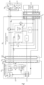
- Fig. 1 is a schematic structural diagram of a charging and discharging control system according to an embodiment of the present invention. This embodiment is applicable to an application scene of automatically changing a working state of a charging and discharging gun integrated with a charging function and a discharging function.
- the charging and discharging gun is electrically connected with a vehicle-mounted charging, the charging and discharging gun is electrically connected with discharging module, the charging and discharging gun is electrically connected with a charging connection module, and the charging and discharging gun is electrically connected with a discharging connection module.
- the charging and discharging control system 100 includes a vehicle-mounted charging and discharging module 10, a charging and discharging gun module 20, a charging connection module 30 and a discharging connection module 40.
- the discharging connection module 40 includes at least one alternating-current discharging receptacle 401.
- the vehicle-mounted charging and discharging module 10 is electrically connected with the charging and discharging gun module 20 through a first connection assembly 50.
- the first connection assembly 50 is configured with a charging control terminal CC, a first connection detecting terminal CP, a first alternating-current positive terminal L, a first alternating-current negative terminal N and a first grounding terminal PE.
- the charging and discharging gun module 20 is electrically connected with the charging connection module 30 through a second connection assembly 60.
- the second connection assembly 60 is configured with a second connection detecting terminal CP', a second alternating-current positive terminal L', a second alternating-current negative terminal N', a second grounding terminal PE', a first input terminal a1 and a second input terminal a2.
- the charging connection module 30 is configured to connect the second connection assembly 60 to an alternating-current power grid, for example, the alternating-current power grid have 220V mains power.
- the discharging connection module 40 is configured to connect to an alternating-current power load, for example, the alternating-current power load includes a vehicle-mounted refrigerator and other emergency appliances.
- an alternating-current discharging receptacle 401 may be one or more of a three-pin receptacle and a five-pin receptacle.
- the three-pin receptacle is configured with a grounding pin, a live wire pin and a neutral wire pin.
- the five-pin receptacle is provided with a grounding pin, two live wire pins and two neutral wire pins.
- the live wire pin is electrically connected with a positive power line L"
- the neutral wire pin is electrically connected with a negative power line N"
- the neutral wire pin is electrically connected with the grounding pin, which improves grounding reliability and safety favorably.
- the first connection assembly 50 includes a vehicle-gun connection receptacle 501 and a vehicle-gun connection plug 502.
- the vehicle-gun connection receptacle 501 is arranged on a vehicle side
- the vehicle-gun connection plug 502 is arranged on a charging and discharging gun side.
- a first end of the charging control terminal CC, a first end of the first connection detecting terminal CP, a first end of the first alternating-current positive terminal L, a first end of the first alternating-current negative terminal N, and a first end of the first grounding terminal PE are arranged on the vehicle-gun connection receptacle 501.
- a second end of the charging control terminal CC, a second end of the first connection detecting terminal CP, a second end of the first alternating-current positive terminal L, a second end of the first alternating-current negative terminal N, and a second end of the first grounding terminal PE are arranged on the vehicle-gun connection plug 502.
- the second connection assembly 60 includes a gun-grid connection receptacle 601 and a gun-grid connection plug 602.
- the gun-grid connection receptacle 601 is arranged on the charging and discharging gun side
- the gun-grid connection plug 602 is arranged on a charging connection module 30 side.
- a first end of the second connection detecting terminal CP', a first end of the second alternating-current positive terminal L', a first end of the second alternating-current negative terminal N', a first end of the second grounding terminal PE', a first end of the first input terminal a1 and a first end of the second input terminal a2 are arranged on the gun-grid connection receptacle 601.
- a second end of the second connection detecting terminal CP', a second end of the second alternating-current positive terminal L', a second end of the second alternating-current negative terminal N', a second end of the second grounding terminal PE', a second end of the first input terminal a1, and a second end of the second input terminal a2 are arranged in the gun-grid connection receptacle 601.
- the vehicle-mounted charging and discharging module 10 includes a vehicle-mounted controller 110 and a vehicle-mounted charging and discharging assembly 120.
- the vehicle-mounted controller 110 is configured to obtain a first detection parameter on a vehicle side of the first connection assembly 50, and control the vehicle-mounted charging and discharging assembly 120 to operate in a charging state or a discharging state according to the first detection parameter.
- the vehicle-mounted charging and discharging assembly 120 includes a vehicle-mounted charger 121 and an inverter unit 122.
- the vehicle-mounted charger 121 is electrically connected with the first end of the first alternating-current positive terminal L and the first end of the first alternating-current negative terminal N through a charging switch Kb.
- the inverter unit 122 is electrically connected with the first end of the first alternating-current positive terminal L and the first end of the first alternating-current negative terminal N through a discharging switch Ka.
- the vehicle-mounted controller 110 controls the charging switch Kb to be switched on and the discharging switch Ka to be switched off, and the vehicle-mounted charger 121 converts an alternating-current charging voltage transmitted through the charging and discharging gun module 20 into a direct-current voltage, to charging a vehicle-mounted power battery.
- the vehicle-mounted controller 110 controls the discharging switch Ka to be switched on and the charging switch Kb to be switched off, and the inverter unit 122 converts a direct-current voltage into an alternating-current charging voltage, and discharges the alternating-current discharging receptacle 401 through a discharging circuit of the charging and discharging gun module 20.
- the charging and discharging gun module 20 includes a gun end control unit 210, and a discharging control switch K1, a charging control switch K2 and a power supply module 220 electrically connected with the gun end control unit 210.
- the power supply module 220 is configured to convert an alternating-current voltage provided through the vehicle-mounted charging and discharging assembly 120 or the charging connection module 30 into a direct-current power supply voltage of the gun end control unit 210.
- the gun end control unit 210 is configured to obtain a second detection parameter on a charging and discharging gun side of the first connection assembly 50, and control the charging control switch K2 to be switched on and the discharging control switch K1 to be switched off in response to the second detection parameter satisfying a preset charging condition, to control the charging connection module 30 charges the vehicle-mounted charging and discharging assembly 120.
- the gun end control unit is configured to control the charging control switch K2 to be switched off and the discharging control switch K1 to be switched on in response to the second detection parameter satisfying a preset discharging condition, to control the vehicle-mounted charging and discharging assembly 120 discharges the discharging connection module 40.
- the discharging control switch K1 and the charging control switch K2 are configured to be relays.
- the gun end control unit 210 is electrically connected with control portions of the relays, and controls a switch portion of the discharging control switch K1 and a switch portion of the charging control switch K2 to be switched on or off, to control a charging circuit and a discharging circuit are connected or disconnected.
- the first detection parameter and the second detection parameter In response to a connection state of the first connection assembly 50 and the second connection assembly 60 changing, the first detection parameter and the second detection parameter have different values, such that the charging and discharging modes may be changed according to the obtained values of the first detection parameter and the second detection parameter.
- the vehicle-gun connection receptacle 501 of the first connection assembly 50 is connected with the vehicle-gun connection plug 502 in a plug-in connection
- the gun-grid connection receptacle 601 of the second connection assembly 60 is connected with the gun-grid connection plug 602 in a plug-in connection
- the values of the first detection parameter and the second detection parameter satisfy the preset charging condition.
- the vehicle-mounted controller 110 controls the charging switch Kb to be switched on and the discharging switch Ka to be switched off
- the gun end control unit 210 controls the charging control switch K2 to be switched on and the discharging control switch K1 to be switched off.
- the charging circuit of the charging and discharging gun module 20 is connected, the discharging circuit is disconnected, and an alternating-current voltage provided through the charging connection module 30 is transmitted to the vehicle-mounted charger 121 through the charging circuit, to execute charging operation.
- the gun-grid connection receptacle 601 of the second connection assembly 60 being disconnected from the gun-grid connection plug 602
- the vehicle-gun connection receptacle 501 of the first connection assembly 50 is connected with the vehicle-gun connection plug 502 in a plug-in connection
- the values of the first detection parameter and the second detection parameter satisfy the preset discharging condition.
- the vehicle-mounted controller 110 controls the charging switch Kb to be switched off and the discharging switch Ka to be switched on, and the gun end control unit 210 controls the charging control switch K2 to be switched off and the discharging control switch K1 to be switched on.
- the charging circuit of the charging and discharging gun module 20 is disconnected, the discharging circuit is connected, and the inverter unit 122 converts a direct-current voltage of the vehicle-mounted power battery into an alternating-current voltage, and transmits the alternating-current voltage to the alternating-current discharging receptacle 401 through the discharging circuit, to execute discharging operation.
- the charging and discharging control system identifies connection states between the vehicle-mounted charging and discharging module, the charging and discharging gun module, the charging connection module and the discharging connection module based on the detection parameters, and automatically changes the charging function and the discharging function based on the detection parameters. Accordingly, the problems of high cost and inconvenient use of the vehicle-mounted charging device and the discharging device are solved, integrated setting and automatic change of the charging function and the discharging function without manually selecting the mode are achieved, a production cost is reduced, the charging connection module and the discharging connection module are prevented from being charged simultaneously, the risk of electric shock caused by misoperation by personnel is reduced, and the reliability and the safety of the system are improved.
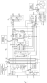
- Fig. 2 is a schematic structural diagram of another charging and discharging control system according to an embodiment of the present invention.
- the charging connection module 30 includes a charging connection control unit 301 and a grid-side connection portion 302.
- the charging connection control unit 301 is electrically connected with an alternating-current power grid through the grid-side connection portion 302, and multiple pins of the charging connection control unit 301 are electrically connected with multiple terminals of the second connection assembly 60 in a one-to-one corresponding manner.
- the charging connection module 30 is configured to charging the vehicle-mounted charging and discharging assembly 120 through the charging and discharging gun module 20 in response to the grid-side connection portion 302 being connected with the alternating-current power grid.
- the grid-side connection portion 302 is configured to be an alternating-current charging plug, and the grid-side connection portion 302 is electrically connected with the alternating-current power grid through an alternating-current receptacle.
- the alternating-current charging plug is configured to be a three-pin plug, a first pin of the alternating-current charging plug is configured to be connected with a live wire of the alternating-current power grid, a second pin of the alternating-current charging plug is configured to be connected with a neutral wire of the alternating-current power grid, and a third pin of the alternating-current charging plug is a grounding pin.
- an operator can connect the gun-grid connection receptacle 601 and the gun-grid connection plug 602 in the plug-in connection, and electrically connect the grid-side connection portion 302 to the alternating-current power grid, such that the second grounding terminal PE' is electrically connected with the first input terminal a1, the second alternating-current positive terminal L' is electrically connected with the live wire of the alternating-current power grid, the second alternating-current negative terminal N' is electrically connected with the neutral wire of the alternating-current power grid, and the second grounding terminal PE' is electrically connected with the grounding pin of the grid-side connection portion 30.
- the charging circuit of the charging and discharging gun module 20 is connected, and the alternating-current voltage provided by the charging connection module 30 is transmitted to the vehicle-mounted charger 121 through the charging circuit, to execute charging operation.
- the charging and discharging gun module 20 further includes a charging and discharging transfer switch K3.
- a control end of the charging and discharging transfer switch K3 is electrically connected with the gun end control unit 210, a first end a of the charging and discharging transfer switch K3 is electrically connected with the first alternating-current negative terminal N, a second end b of the charging and discharging transfer switch K3 is electrically connected with a negative power line N" of the discharging connection module 40, and a third end c of the charging and discharging transfer switch K3 is electrically connected with the second alternating-current negative terminal N'.
- the gun end control unit 210 is further configured to control the first end a to be connected with the third end c in response to the second detection parameter satisfies the preset charging condition, or control the first end a to be connected with the second end b in response to the second detection parameter satisfying the preset discharging condition.
- the charging and discharging transfer switch K3 is configured to be a relay, the first end a of the charging and discharging transfer switch K3 is a normally open and normally closed common contact of the relay, the second end b of the charging and discharging transfer switch K3 is a normally closed contact of the relay, and the third end c of the charging and discharging transfer switch K3 is a normally open contact of the relay.
- the gun end control unit 210 controls the charging control switch K2 to be switched on, controls the discharging control switch K1 to be switched off, and controls the first end a and the third end c of the charging and discharging transfer switch K3 to be connected.
- the gun end control unit 210 controls the charging control switch K2 to be switched off, controls the discharging control switch K1 to be switched on, and controls the first end a and the second end b of the charging and discharging transfer switch K3 to be connected.
- a first end of the charging control terminal CC is electrically connected with the vehicle-mounted controller 110, and a second end of the charging control terminal CC is electrically connected with a first pin CC I of the gun end control unit 210 through a first high-resistance type operational amplifier U1.
- a first end of the first connection detecting terminal CP is electrically connected with the vehicle-mounted controller 110, the first end of the first connection detecting terminal CP is further grounded through a grounding resistor assembly 130, a second end of the first connection detecting terminal CP is electrically connected with a second pin CP I of the gun end control unit 210 through a second high-resistance type operational amplifier U2, and the second end of the first connection detecting terminal CP is further electrically connected with the second connection detecting terminal CP'.
- a first end of the first alternating-current positive terminal L is electrically connected with a positive end of the vehicle-mounted charging and discharging assembly 120, a second end of the first alternating-current positive terminal N is electrically connected with the discharging connection module 40 through the discharging control switch K1, and the second end of the first alternating-current positive terminal L is further electrically connected with the second alternating-current positive terminal L' through the charging control switch K2.
- a first end of the first alternating-current negative terminal N is electrically connected with a negative end of the vehicle-mounted charging and discharging assembly 120, and a second end of the first alternating-current negative terminal N is electrically connected with a negative power line of the alternating-current discharging receptacle 201 and the second alternating-current negative terminal N' separately.
- a first end of the first grounding terminal PE is grounded, a second end of the first grounding terminal PE is electrically connected with the charging control terminal through a gun head resistor assembly 230, and a second end of the first grounding terminal PE is further electrically connected with the second grounding terminal PE'.
- a first end of the first input terminal a1 is electrically connected with the gun head resistor assembly 230, and a second end of the first input terminal a1 is electrically connected with the charging connection control unit 301 and the second end of the first input terminal a1 is electrically connected with the second grounding terminal PE'.
- a first end of the second input terminal a2 is electrically connected with a third pin a2 I of the gun end control unit 210, and a second end of the second input terminal a2 is electrically connected with the charging connection control unit 301.
- a first end of the first grounding terminal PE can be electrically connected with vehicle body geoelectric, to achieve a equivalently grounding.
- the grounding resistor assembly 130 includes a fourth resistor R4, a fifth resistor R5, and a grounding switch S2 connected in series to the fifth resistor R5.
- the grounding switch S2 is switched on.
- the grounding switch S2 is switched off.
- the vehicle-mounted controller 110 may obtain a voltage signal of the charging control terminal CC and the first connection detecting terminal CP arranged on the vehicle side, and take the voltage signals as a first detection signal.
- the gun end control unit 210 may obtain a voltage signal of the charging control terminal CC and the first connection detecting terminal CP on the charging and discharging gun side, and take the voltage signal as a second detection signal.
- the gun head resistor assembly 230 includes a first resistor R1, a second resistor R2, a third resistor R3 and a gun end button S1.
- the gun end button S1 is configured with a normally open and normally closed common pin Sa, a normally open connection pin Sb and a normally closed connection pin Sc.
- the normally open connection pin Sb is electrically connected with a first end of the first resistor R1, a second end of the first resistor R1 is electrically connected with the first grounding terminal PE, the normally open and normally closed common pin Sa is electrically connected with the charging control terminal CC, the normally closed connection pin Sc is electrically connected with a first end of the second resistor R2 and a first end of the third resistor R3, a second end of the second resistor R2 is electrically connected with the first grounding terminal PE, and a second end of the third resistor R3 is electrically connected with the first input terminal a1.
- an operator may press the gun end button S1, to connect the normally open and normally closed common pin Sa to the normally open connection pin Sb, and disconnect the normally open and normally closed common pin Sa from the normally closed connection pin Sc.
- an operator releases the gun end button S1, such that the normally open and normally closed common pin Sa is disconnected from the normally open connection pin Sb, and the normally open and normally closed common pin Sa is connected with the normally closed connection pin Sc.
- the first input terminal a1 is electrically connected with the second grounding terminal PE'
- the third resistor R3 is electrically connected with the first grounding terminal PE through the first input terminal a1 and the second grounding terminal PE'.
- a resistance value of the gun head resistor assembly 230 is equal to a parallel resistance value of the second resistor R2 and the third resistor R3, and the first connection detecting terminal CP is electrically connected with the alternating-current power grid, such that a voltage value of the first connection detecting terminal CP is greater than zero.
- the third resistor R3 is disconnected from the first grounding terminal PE.
- the resistance value of the gun head resistor assembly 230 is equal to a resistance value of the second resistor R2
- the first connection detecting terminal CP is disconnected from the alternating-current power grid
- a voltage value of the first connection detecting terminal CP is equal to zero, such that the gun end control unit 210 may identify a connection state of the connection assembly through detecting the parameter value, and execute automatic change of the charging and discharging states.
- the first detection parameter includes a first voltage parameter Vcp of the first connection detecting terminal CP arranged on the vehicle side and a first resistor parameter R10 between the charging control terminal and the first grounding terminal.
- the second detection parameter includes a second voltage parameter Vcp' of the first connection detecting terminal arranged on the charging and discharging gun side and a second resistor parameter R20 between the charging control terminal CC and the first grounding terminal PE.
- the first voltage parameter Vcp is equal to the second voltage parameter Vcp'
- the first resistor parameter R10 is equal to the second resistor parameter R20.
- the vehicle-mounted controller 110 identifies a connection state of the first connection assembly 50 and the second connection assembly 60 based on the first detection parameter, and controls the charging switch Kb and the discharging switch Ka to be switched on or off.
- the gun end control unit 210 identifies the connection state of the first connection assembly 50 and the second connection assembly 60 based on the first detection parameter, and controls the charging control switch K2 and the discharging control switch K1 to be switched on or off to change the charging mode and the discharging mode.
- a resistance value of the first resistor R1 is 3.3 kilohms
- a resistance value of the second resistor R2 is 2.1 kilohms
- a resistance value of the third resistor R3 is 1 kilohm
- a charging-discharging mode change process is described as follows.
- the vehicle-mounted controller 110 determines the first connection assembly 50 and the second connection assembly 60 are connected, and the vehicle-mounted controller 110 controls the charging switch Kb to be switched on and the discharging switch Ka to be switched off.
- the gun end control unit 210 determines that the first connection assembly 50 and the second connection assembly 60 are connected, and the gun end control unit 210 controls the charging control switch K2 to be switched on and the discharging control switch K1 to be switched off. In this case, the charging circuit of the charging and discharging gun module 20 is connected, and the discharging circuit is disconnected, to execute charging operation.
- the vehicle-mounted controller 110 determines that the first connection assembly 50 is connected and the second connection assembly 60 is disconnected, and the vehicle-mounted controller 110 controls the charging switch Kb to be switched off and the discharging switch Ka to be switched on.
- the gun end control unit 210 determines that the first connection assembly 50 is connected and the second connection assembly 60 is disconnected, and the gun end control unit 210 controls the charging control switch K2 to be switched on and the discharging control switch K1 to be switched off. In this case, the charging circuit of the charging and discharging gun module 20 is disconnected, and the discharging circuit is connected to execute discharging operation.
- Those skilled in the art can also set a trigger button between the second end of the third resistor R3 and the first grounding terminal PE, and an operator can adjust a resistance value between the charging control terminal CC and the first grounding terminal PE through pressing the button to change the charging mode and the discharging mode, which is not limited herein.
- the charging and discharging gun module 20 further includes at least one negative temperature coefficient (NTC) sensor.
- the NTC sensor is configured to measure a temperature in the charging and discharging gun and send a measurement result to the gun end control unit 210.
- the gun end control unit 210 is further configured to control the discharging control switch K1, the charging control switch K2 and the charging and discharging transfer switch K3 to be disconnected in response to the measurement result being beyond a preset temperature threshold.
- three NTC sensors may be configured.
- the three NTC sensors include a first temperature sensor NTC1, a second temperature sensor NTC2, and a third temperature sensor NTC3.
- the first temperature sensor NTC1 is arranged between the second alternating-current positive terminal L 'and the second alternating-current negative terminal N' of the gun-grid connection receptacle 601, and the first temperature sensor NTC1 is configured to measure a heating temperature of the gun-grid connection receptacle 601.
- the second temperature sensor NTC2 is arranged on a shell of the discharging control switch K1, and the second temperature sensor NTC2 is configured to measure a heating temperature of the discharging control switch K1.
- the third temperature sensor NTC3 is arranged between the positive power line L" and the negative power line N", and the third temperature sensor NTC3 is configured to measure a heating temperature of a power supply line of the discharging connection module 40.
- the gun end control unit 210 controls all the discharging control switch K1, the charging control switch K2, and the charging and discharging transfer switch K3 to be switched off.
- the preset temperature threshold corresponding to different temperature sensors may be set to the same or different values, which is not limited herein.
- the power supply module 220 includes a first filter unit 221, a second filter unit 222 and an alternating current-direct current conversion unit 223.
- a positive input end of the first filter unit 221 is electrically connected with the first alternating-current positive terminal L
- a negative input end of the first filter unit 221 is electrically connected with the first alternating-current negative terminal N
- a positive output end of the first filter unit 221 is electrically connected with a positive input end of the alternating current-direct current conversion unit 223 through a first diode D1
- a negative output end of the first filter unit 221 is electrically connected with a negative input end of the alternating current-direct current conversion unit 223.
- a positive input end of the second filter unit 222 is electrically connected with the second alternating-current positive terminal L', a negative input end of the second filter unit 222 is electrically connected with the second alternating-current negative terminal N', a positive output end of the second filter unit 222 is electrically connected with a positive input end of the alternating current-direct current conversion unit 223 through a second diode D2, a negative output end of the second filter unit 222 is electrically connected with a negative input end of the alternating current-direct current conversion unit 223, and an output end of the alternating current-direct current conversion unit 223 is electrically connected with a power supply end of the gun end control unit 210.
- the alternating current-direct current conversion unit 223 is configured to convert the alternating-current voltage provided by the vehicle-mounted charging and discharging assembly 120 or the charging connection module 30 into a direct-current power supply voltage of the gun end control unit 210 to supply power to the gun end control unit 210.
- the second filter unit 222 and the alternating current-direct current conversion unit 223 convert an alternating-current voltage provided by the charging connection module 30 into a direct-current voltage of the gun end control unit 210, to supply power to the gun end control unit 210.
- the first filter unit 221 and the alternating current-direct current conversion unit 223 convert an alternating-current voltage provided by the vehicle-mounted charging and discharging assembly 120 into a direct-current power supply voltage of the gun end control unit 210, to supply power to the gun end control unit 210.
- bidirectional power supply can be achieved during charging and discharging time period, and system reliability is improved.
- Those skilled in the art can also convert the alternating-current voltage provided by the vehicle-mounted charging and discharging assembly 120 or the charging connection module 30 into the direct-current power supply voltage of the gun end control unit through cooperation of multiple relays and the gun end control unit 210, which is not limited herein.
- Fig. 3 is a schematic structural diagram of yet another charging and discharging control system according to an embodiment of the present invention.
- the charging and discharging gun module 20 further includes a failure detection assembly 240.
- a first detection end of the failure detection assembly 240 is electrically connected with an output end of the discharging control switch K1, a second detection end of the failure detection assembly 240 is electrically connected with a second end of the charging and discharging transfer switch K3, an output end of the failure detection assembly 240 is electrically connected with a detection pin TEST of the gun end control unit 210, and the failure detection assembly 240 is configured to detect whether the discharging control switch K1 or the charging and discharging transfer switch K3 has a failure, and send a failure detection result to the gun end control unit 210.
- the gun end control unit 210 is further configured to control the charging and discharging transfer switch K3 and the charging control switch K2 to be disconnected in response to a first failure signal of the discharging control switch K1 being received, and control the discharging control switch K1 and the charging control switch K2 to be disconnected in response to a second failure signal of the charging and discharging transfer switch K3 being received.
- the failure types of the discharging control switch K1 and the charging and discharging transfer switch K3 include switch failure or adhesion failure.
- FIG. 4 is a schematic diagram of mode change of a charging and discharging control system according to an embodiment 1 of the present invention.
- a working mode of the charging and discharging control system in this embodiment includes a disconnected state, a charging connected state, a discharging state, a charging state, or a failure state.
- a process of changing the working mode of the charging and discharging control system is as follows:
- T01 A disconnected state changes to a discharging state
- the gun end control unit 210 controls the discharging control switch K1 to be switched on, controls the charging control switch K2 to be switched off, and controls the first end a and the second end b of the charging and discharging transfer switch K3 to be connected, such that the charging and discharging control system 100 enters the discharging state.
- T02 A discharging state changes to a failure state
- T03 A discharging state changes to a disconnected state
- the gun end control unit 210 controls the discharging control switch K1 to be switched off, controls the charging control switch K2 to be switched off, and controls the first end a and the second end b of the charging and discharging transfer switch K3 to be connected, such that the charging and discharging control system 100 enters the disconnected state.
- T04 A discharging state changes to a charging state
- the gun end control unit 210 controls the discharging control switch K1 to be switched off, controls the charging control switch K2 to be switched on, and controls the first end a and the third end c of the charging and discharging transfer switch K3 to be connected, such that the charging and discharging control system 100 enter the charging state.
- T05 A charging state changes to a failure state
- T06 A charging state changes to a discharging state
- the gun end control unit 210 detects the first detection parameter and the second detection parameter in real time. In response to determining that the first input terminal a1 is disconnected from the first grounding terminal PE based on the first detection parameter and the second detection parameter, the gun end control unit 210 controls the discharging control switch K1 to be switched on, controls the charging control switch K2 to be switched off, and controls the first end a and the second end b of the charging and discharging transfer switch K3 to be connected, such that the charging and discharging control system 100 enters the discharging state.
- T07 A disconnected state changes to a charging connected state
- the gun end control unit 210 In response to determining that the first input terminal a1 is connected with the first grounding terminal PE and the first connection assembly 50 is disconnected based on the first detection parameter and the second detection parameter, the gun end control unit 210 outputs no control signal, and the discharging control switch K1, the charging control switch K2, and the charging and discharging transfer switch K3 maintain the current state, such that the charging and discharging control system 100 enters the charging connected state.
- T08 A charging connected state changes to a charging state
- the gun end control unit 210 controls the discharging control switch K1 to be switched off, controls the charging control switch K2 to be switched on, and controls the first end a and the third end c of the charging and discharging transfer switch K3 to be connected, such that the charging and discharging control system 100 enters the charging state.
- a connection state of the connection assembly can be identified based on the detection parameters, and a charging mode and a discharging mode can be automatically changed.
- Embodiment 2 of the present invention provides a transport. This embodiment is applicable to automatic change of a charging function and a discharging function through a set of apparatuses.
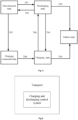
- Fig. 5 is a schematic structural diagram of a means of transport according to an embodiment 2 of the present invention.
- the transport 200 includes the charging and discharging control system 100 above.
- the transport 200 can be an electric vehicle.
- the transport provided in the present invention is configured with a charging and discharging control system.
- the charging and discharging control system is configured with a vehicle-mounted charging and discharging module, a charging and discharging gun module, a charging connection module and a discharging connection module.
- the vehicle-mounted charging and discharging module is electrically connected with the charging and discharging gun module through a first connection assembly, and the charging and discharging gun module is electrically connected with the charging connection module through a second connection assembly.
- the vehicle-mounted charging and discharging module obtains a first detection parameter on a vehicle side through a vehicle-mounted controller, and controls the vehicle-mounted charging and discharging assembly to operate in a charging state or a discharging state based on the first detection parameter.
- the charging and discharging gun module obtains a second detection parameter on a charging and discharging gun side through a gun end control unit.
- the charging and discharging gun module controls a charging control switch to be switched on and a discharging control switch to be switched off in response to the second detection parameter satisfying a preset charging condition, such that the charging connection module charges the vehicle-mounted charging and discharging assembly, or the charging and discharging gun module controls the charging control switch to be switched off and the discharging control switch to be switched on in response to the second detection parameter satisfying a preset discharging condition, such that the vehicle-mounted charging and discharging assembly discharges the discharging connection module.
- a connection state of the connection assembly is determined based on the detection parameters, and the charging function and the discharging function are automatically changed.
- the problems of high cost and inconvenient use of the vehicle-mounted charging apparatus and the discharging apparatus are solved, and integrated setting and automatic change of the charging function and the discharging function without manually selecting a mode are achieved.
- a production cost is reduced, the charging connection module and the discharging connection module are prevented from being charged simultaneously, and the reliability and the safety of the system are improved.
- embodiments of the present invention provides a charging and discharging control method.
- This embodiment is applicable to an application scene where a working state of a charging and discharging gun integrated with a charging function and a discharging function is automatically changed.
- a charging and discharging gun module is electrically connected with a vehicle-mounted charging and discharging module, a charging connection module, and a discharging connection module separately.
- the charging and discharging gun module is electrically connected with the vehicle-mounted charging and discharging module through a first connection assembly.
- the charging and discharging gun module is electrically connected with the charging connection module through a second connection assembly.
- Fig. 6 is a flowchart of a charging and discharging control method according to an embodiment of the present invention.
- the charging and discharging control method includes: At step S1: obtain a first detection parameter on a vehicle side, and control a vehicle-mounted charging and discharging module to operate in a charging state or a discharging state based on the first detection parameter.
- step S2 obtain a second detection parameter on a charging and discharging gun side.
- the first detection parameter includes a first voltage parameter of a first connection detecting terminal arranged on the vehicle side and a first resistor parameter between a charging control terminal and a first grounding terminal.
- the second detection parameter includes a second voltage parameter of the first connection detecting terminal arranged on the charging and discharging gun side and a second resistor parameter between the charging control terminal and the first grounding terminal.
- the first detection parameter and the second detection parameter in response to a connection state of the first connection assembly and the second connection assembly changing, have different values, such that the charging and discharging modes may be changed based on the obtained values of the first detection parameter and the second detection parameter.
- step S3 determine whether the second detection parameter satisfies a preset charging condition or a preset discharging condition.
- step S4 In response to the second detection parameter satisfying the preset charging condition, the step S4 is executed. In response to the second detection parameter satisfying the preset discharging condition, the step S5 is executed. Otherwise, the step S6 is executed.
- step S4 control the vehicle-mounted charging and discharging module and a charging and discharging gun module to execute charging operation.
- step S5 control the vehicle-mounted charging and discharging module and the charging and discharging gun module to execute discharging operation.
- step S6 control the vehicle-mounted charging and discharging module and the charging and discharging gun module to stop working.
- a charging control switch, a discharging control switch and a charging and discharging transfer switch may be provided, and a charging mode and a discharging mode may be automatically changed through controlling the charging control switch, the discharging control switch and the charging and discharging transfer switch to be switched on or off.
- the charging control switch in response to the second detection parameter satisfying the preset charging condition, the charging control switch is controlled to be switched on, and a charging branch contact of the charging and discharging transfer switch is controlled to be switched on, such that a charging circuit is connected.
- the discharging control switch is control to be switched on, and a discharging branch contact of the charging and discharging transfer switch is controlled to be switched on, such that a discharging circuit is connected.
- the charging control switch and the discharging control switch are not switched on simultaneously, such that the charging connection module and the discharging connection module are prevented from being charged simultaneously, the risk of electric shock caused by misoperation by personnel is reduced, and the reliability and the safety of the system are improved.
- the charging and discharging control method further includes: obtain a temperature in a charging and discharging gun; determine a temperature measurement result is beyond a preset temperature threshold; and determine that the charging and discharging gun is in a failure state in response to the temperature measurement result being beyond the preset temperature threshold, and control a discharging control switch, a charging control switch and a charging and discharging transfer switch to be switched off.
- the charging and discharging control method further includes: detect whether a discharging control switch or a charging and discharging transfer switch has a failure; control the charging and discharging transfer switch and the charging control switch to be switched off in response to the discharging control switch has a failure; and control the discharging control switch and the charging control switch to be switched off in response to the charging and discharging transfer switch has a failure.
- the charging and discharging control method further includes: in a charging process, convert an alternating-current voltage provided through a charging connection module into a direct-current power supply voltage, to supply power to a control unit of the charging and discharging gun; and in a discharging process, convert an alternating-current voltage provided through the vehicle-mounted charging and discharging module into a direct-current power supply voltage, to supply power to the control unit of the charging and discharging gun.
- a vehicle-mounted controller obtains a first detection parameter on a vehicle side, and controls a vehicle-mounted charging and discharging assembly to work in a charging state or a discharging state based on the first detection parameter.
- a gun end control unit obtains a second detection parameter on a charging and discharging gun side, and controls a charging control switch to be switched on and a discharging control switch to be switched off in response to the second detection parameter satisfies a preset charging condition, to execute charging operation, or the gun end control unit controls the charging control switch to be switched off and the discharging control switch to be switched on in response to the second detection parameter satisfying a preset discharging condition, to execute discharging operation.
- a connection state of the connection assembly is determined based on the detection parameters, and the charging function and the discharging function are automatically changed.
- the problems of high cost and inconvenient operate of the vehicle-mounted charging device and the discharging device are solved, and integrated setting and automatic change of the charging function and the discharging function without manually selecting a mode are achieved.
- a production cost is reduced, the charging connection module and the discharging connection module are prevented from being charged simultaneously, and the reliability and the safety of the system are improved.
Landscapes
- Engineering & Computer Science (AREA)
- Power Engineering (AREA)
- Transportation (AREA)
- Mechanical Engineering (AREA)
- Life Sciences & Earth Sciences (AREA)
- Sustainable Development (AREA)
- Sustainable Energy (AREA)
- Charge And Discharge Circuits For Batteries Or The Like (AREA)
- Electric Propulsion And Braking For Vehicles (AREA)
Abstract
Description
- The present invention claims priority to
Chinese Patent Application No. 202011563449.0, filed to the Chinese Patent Office on December 25, 2020 - The present invention relates to the technical field of charging and discharging control, in particular to a charging and discharging control system and method, and a vehicle.
- As battery life of electric vehicles prolongs, some vehicle manufacturers propose a function of Vehicle to Load (V2L), which provides Alternating Current (AC) power supply for an external general-purpose electrical load through a vehicle power supply.
- In the related art, a vehicle has to be equipped with a charge gun and a discharge gun, in order to achieve AC charge and V2L, resulting in inconvenient use, occupation of a large storage space, and increase in the purchase cost and maintenance cost.
- At least some embodiments of the present invention provides a charging and discharging control system. A charging branch circuit and a discharging branch circuit are arranged in an integrated manner to solve the problems of high cost and inconvenient use of a vehicle-mounted charging device and a vehicle-mounted discharging device.
- The present invention provides a charging and discharging control system, including: a vehicle-mounted charging and discharging module, a charging and discharging gun module, a charging connection module and a discharging connection module. The discharging connection module includes at least one alternating-current discharging receptacle, the vehicle-mounted charging and discharging module is electrically connected with the charging and discharging gun module through a first connection assembly, and the charging and discharging gun module is electrically connected with the charging connection module through a second connection assembly. The vehicle-mounted charging and discharging module includes a vehicle-mounted controller and a vehicle-mounted charging and discharging assembly, and the vehicle-mounted controller is configured to obtain a first detection parameter on a vehicle side, and control the vehicle-mounted charging and discharging assembly to operate in a charging state or a discharging state according to the first detection parameter. The charging and discharging gun module includes a gun end control unit, and a discharging control switch, a charging control switch and a power supply module, wherein the discharging control switch, the charging control switch and the power supply module are electrically connected with the gun end control unit, the power supply module is configured to convert an alternating-current voltage provided through the vehicle-mounted charging and discharging assembly or the charging connection module into a direct-current power supply voltage of the gun end control unit. The gun end control unit is configured to obtain a second detection parameter on a charging and discharging gun side, and control the charging control switch to be switched on and the discharging control switch to be switched off in response to the second detection parameter satisfying a preset charging condition, to control the charging connection module charges the vehicle-mounted charging and discharging assembly; or the gun end control unit is configured to control the charging control switch to be switched off and the discharging control switch to be switched on in response to the second detection parameter satisfying a preset discharging condition, to control the vehicle-mounted charging and discharging assembly discharges the discharging connection module.
- In an optional embodiment, the first connection assembly is configured with a charging control terminal, a first connection detecting terminal, a first alternating-current positive terminal, a first alternating-current negative terminal and a first grounding terminal, and the second connection assembly is arranged with a second connection detecting terminal, a second alternating-current positive terminal, a second alternating-current negative terminal, a second grounding terminal, a first input terminal and a second input terminal. A first end of the charging control terminal is electrically connected with the vehicle-mounted controller, and a second end of the charging control terminal is electrically connected with a first pin of the gun end control unit through a high-resistance type operational amplifier. A first end of the first connection detecting terminal is electrically connected with the vehicle-mounted controller, the first end of the first connection detecting terminal is further grounded through a grounding resistor assembly, a second end of the first connection detecting terminal is electrically connected with a second pin of the gun end control unit through a high-resistance type operational amplifier, and the second end of the first connection detecting terminal is further electrically connected with the second connection detecting terminal. A first end of the first alternating-current positive terminal is electrically connected with a positive end of the vehicle-mounted charging and discharging assembly, a second end of the first alternating-current positive terminal is electrically connected with the discharging connection module through the discharging control switch, and the second end of the first alternating-current positive terminal is further electrically connected with the second alternating-current positive terminal through the charging control switch. A first end of the first alternating-current negative terminal is electrically connected with a negative end of the vehicle-mounted charging and discharging assembly, and a second end of the first alternating-current negative terminal is respectively electrically connected with a negative power line of the alternating-current discharging receptacle and the second alternating-current negative terminal. A first end of the first grounding terminal is grounded, a second end of the first grounding terminal is electrically connected with the charging control terminal through a gun head resistor assembly, and a second end of the first grounding terminal is further electrically connected with the second grounding terminal. A first end of the first input terminal is respectively electrically connected with the gun head resistor assembly, and a second end of the first input terminal is electrically connected with the charging connection module and the second grounding terminal separately. A first end of the second input terminal is electrically connected with a third pin of the gun end control unit, and a second end of the second input terminal is electrically connected with the charging connection module.
- In an optional embodiment, the gun head resistor assembly includes a first resistor, a second resistor, a third resistor and a gun end button. The gun end button is configured with a normally open and normally closed common pin, a normally open connection pin and a normally closed connection pin. The normally open connection pin is electrically connected with a first end of the first resistor, a second end of the first resistor is electrically connected with the first grounding terminal, the normally open and normally closed common pin is electrically connected with the charging control terminal, the normally closed connection pin is respectively electrically connected with a first end of the second resistor and a first end of the third resistor, a second end of the second resistor is electrically connected with the first grounding terminal, and a second end of the third resistor is electrically connected with the first input terminal.
- In an optional embodiment, the charging and discharging gun module further includes a charging and discharging transfer switch. A control end of the charging and discharging transfer switch is electrically connected with the gun end control unit, a first end of the charging and discharging transfer switch is electrically connected with the first alternating-current negative terminal, a second end of the charging and discharging transfer switch is electrically connected with a negative power line of the discharging connection module, and a third end of the charging and discharging transfer switch is electrically connected with the second alternating-current negative terminal. The gun end control unit is further configured to control the first end to be connected with the third end in response to the second detection parameter satisfying the preset charging condition, or control the first end to be connected with the second end in response to the second detection parameter satisfying the preset discharging condition.
- In an optional embodiment, the charging and discharging gun module further includes at least one temperature sensor. The temperature sensor is configured to measure a temperature in the charging and discharging gun to obtain a measurement result and send the measurement result to the gun end control unit. The gun end control unit is further configured to control the discharging control switch, the charging control switch and the charging and discharging transfer switch to be disconnected in response to the measurement result being beyond a preset temperature threshold.
- In an optional embodiment, the charging and discharging gun module further includes a failure detection assembly. A first detection end of the failure detection assembly is electrically connected with an output end of the discharging control switch, a second detection end of the fault detection assembly is electrically connected with a second end of the charging and discharging transfer switch, an output end of the fault detection assembly is electrically connected with a detection pin of the gun end control unit, and the failure detection assembly is configured to detect whether the discharging control switch or the charging and discharging transfer switch exists a failure to obtain a failure detection result, and send the failure detection result to the gun end control unit. The gun end control unit is further configured to control the charging and discharging transfer switch and the charging control switch to be disconnected in response to receiving a first fault signal of the discharging control switch, and control the discharging control switch and the charging control switch to be disconnected in response to receiving a second fault signal of the charging and discharging transfer switch.
- In an optional embodiment, the first detection parameter includes a first voltage parameter of the first connection detecting terminal arranged on the vehicle side and a first resistor parameter between the charging control terminal and the first grounding terminal. The second detection parameter includes a second voltage parameter of the first connection detecting terminal arranged on the charging and discharging gun side and a second resistor parameter between the charging control terminal and the first grounding terminal.
- In an optional embodiment, the power supply module includes a first filter unit, a second filter unit and an alternating current-direct current conversion unit. A positive input end of the first filter unit is electrically connected with the first alternating-current positive terminal, a negative input end of the first filter unit is electrically connected with the first alternating-current negative terminal, a positive output end of the first filter unit is electrically connected with a positive input end of the alternating current-direct current conversion unit through a first diode, and a negative output end of the first filter unit is electrically connected with a negative input end of the alternating current-direct current conversion unit. A positive input end of the second filter unit is electrically connected with the second alternating-current positive terminal, a negative input end of the second filter unit is electrically connected with the second alternating-current negative terminal, a positive output end of the second filter unit is electrically connected with a positive input end of the alternating current-direct current conversion unit through a second diode, a negative output end of the second filter unit is electrically connected with a negative input end of the alternating current-direct current conversion unit, and an output end of the alternating current-direct current conversion unit is electrically connected with a power supply end of the gun end control unit. The alternating current-direct current conversion unit is configured to convert the alternating-current voltage configured by the vehicle-mounted charging and discharging assembly or the charging connection module into a direct-current power supply voltage of the gun end control unit to supply power to the gun end control unit.
- In an optional embodiment, the charging connection module includes a charging connection control unit and a grid-side connection portion. The charging connection control unit is electrically connected with an alternating-current power grid through the grid-side connection portion, and multiple pins of the charging connection control unit are electrically connected with multiple terminals of the second connection assembly in a one-to-one corresponding manner. The charging connection module is configured to charging the vehicle-mounted charging and discharging assembly through the charging and discharging gun module in response to the grid-side connection portion being connected with the alternating-current power grid.
- The present invention further provides a transport, including the charging and discharging control system above-mentioned.
- The present invention further provides a charging and discharging control method, applied to controlling charging and discharging states of a vehicle-mounted charging and discharging module and a charging and discharging gun module, and including:
- obtaining a first detection parameter on a vehicle side, and controlling the vehicle-mounted charging and discharging module to work in a charging state or a discharging state according to the first detection parameter;
- obtaining a second detection parameter on a charging and discharging gun side;
- determining whether the second detection parameter satisfies a preset charging condition or a preset discharging condition;
- controlling the vehicle-mounted charging and discharging module and the charging and discharging gun module to execute charging operation in response to the second detection parameter satisfying the preset charging condition;
- controlling the vehicle-mounted charging and discharging module and the charging and discharging gun module to execute discharging operation in response to the second detection parameter satisfying the preset discharging condition.
-
-
Fig. 1 is a schematic structural diagram of a charging and discharging control system according to an embodiment of the present invention; -
Fig. 2 is a schematic structural diagram of another charging and discharging control system according to an embodiment of the present invention; -
Fig. 3 is a schematic structural diagram of yet another charging and discharging control system according to an embodiment of the present invention; -
Fig. 4 is a schematic diagram of mode change of a charging and discharging control system according to an embodiment of the present invention; -
Fig. 5 is a schematic structural diagram of a transport according to an embodiment of the present invention; -
Fig. 6 is a flowchart of a charging and discharging control method according to an embodiment of the present invention. - The present invention will be elaborated hereafter in conjunction with the accompanying drawings and embodiments. The particular embodiments described herein are for the purpose of explanation of the present invention only. For ease of description, only portions associated with the present invention are shown in the accompanying drawings.
-
Fig. 1 is a schematic structural diagram of a charging and discharging control system according to an embodiment of the present invention. This embodiment is applicable to an application scene of automatically changing a working state of a charging and discharging gun integrated with a charging function and a discharging function. The charging and discharging gun is electrically connected with a vehicle-mounted charging, the charging and discharging gun is electrically connected with discharging module, the charging and discharging gun is electrically connected with a charging connection module, and the charging and discharging gun is electrically connected with a discharging connection module. - As shown in
Fig. 1 , the charging and discharging control system 100 includes a vehicle-mounted charging and dischargingmodule 10, a charging and discharginggun module 20, acharging connection module 30 and a dischargingconnection module 40. The dischargingconnection module 40 includes at least one alternating-current discharging receptacle 401. The vehicle-mounted charging and dischargingmodule 10 is electrically connected with the charging and discharginggun module 20 through afirst connection assembly 50. Thefirst connection assembly 50 is configured with a charging control terminal CC, a first connection detecting terminal CP, a first alternating-current positive terminal L, a first alternating-current negative terminal N and a first grounding terminal PE. The charging and discharginggun module 20 is electrically connected with thecharging connection module 30 through asecond connection assembly 60. Thesecond connection assembly 60 is configured with a second connection detecting terminal CP', a second alternating-current positive terminal L', a second alternating-current negative terminal N', a second grounding terminal PE', a first input terminal a1 and a second input terminal a2. - The
charging connection module 30 is configured to connect thesecond connection assembly 60 to an alternating-current power grid, for example, the alternating-current power grid have 220V mains power. The dischargingconnection module 40 is configured to connect to an alternating-current power load, for example, the alternating-current power load includes a vehicle-mounted refrigerator and other emergency appliances. - In this embodiment, an alternating-
current discharging receptacle 401 may be one or more of a three-pin receptacle and a five-pin receptacle. The three-pin receptacle is configured with a grounding pin, a live wire pin and a neutral wire pin. The five-pin receptacle is provided with a grounding pin, two live wire pins and two neutral wire pins. The live wire pin is electrically connected with a positive power line L", the neutral wire pin is electrically connected with a negative power line N", and the neutral wire pin is electrically connected with the grounding pin, which improves grounding reliability and safety favorably. - In this embodiment, the
first connection assembly 50 includes a vehicle-gun connection receptacle 501 and a vehicle-gun connection plug 502. The vehicle-gun connection receptacle 501 is arranged on a vehicle side, and the vehicle-gun connection plug 502 is arranged on a charging and discharging gun side. A first end of the charging control terminal CC, a first end of the first connection detecting terminal CP, a first end of the first alternating-current positive terminal L, a first end of the first alternating-current negative terminal N, and a first end of the first grounding terminal PE are arranged on the vehicle-gun connection receptacle 501. A second end of the charging control terminal CC, a second end of the first connection detecting terminal CP, a second end of the first alternating-current positive terminal L, a second end of the first alternating-current negative terminal N, and a second end of the first grounding terminal PE are arranged on the vehicle-gun connection plug 502. - In this embodiment, the
second connection assembly 60 includes a gun-grid connection receptacle 601 and a gun-grid connection plug 602. The gun-grid connection receptacle 601 is arranged on the charging and discharging gun side, and the gun-grid connection plug 602 is arranged on acharging connection module 30 side. A first end of the second connection detecting terminal CP', a first end of the second alternating-current positive terminal L', a first end of the second alternating-current negative terminal N', a first end of the second grounding terminal PE', a first end of the first input terminal a1 and a first end of the second input terminal a2 are arranged on the gun-grid connection receptacle 601. A second end of the second connection detecting terminal CP', a second end of the second alternating-current positive terminal L', a second end of the second alternating-current negative terminal N', a second end of the second grounding terminal PE', a second end of the first input terminal a1, and a second end of the second input terminal a2 are arranged in the gun-grid connection receptacle 601. - Optionally, as shown in
Fig. 1 , the vehicle-mounted charging and dischargingmodule 10 includes a vehicle-mountedcontroller 110 and a vehicle-mounted charging and dischargingassembly 120. The vehicle-mountedcontroller 110 is configured to obtain a first detection parameter on a vehicle side of thefirst connection assembly 50, and control the vehicle-mounted charging and dischargingassembly 120 to operate in a charging state or a discharging state according to the first detection parameter. - The vehicle-mounted charging and discharging
assembly 120 includes a vehicle-mountedcharger 121 and aninverter unit 122. The vehicle-mountedcharger 121 is electrically connected with the first end of the first alternating-current positive terminal L and the first end of the first alternating-current negative terminal N through a charging switch Kb. Theinverter unit 122 is electrically connected with the first end of the first alternating-current positive terminal L and the first end of the first alternating-current negative terminal N through a discharging switch Ka. - In a charging process, the vehicle-mounted
controller 110 controls the charging switch Kb to be switched on and the discharging switch Ka to be switched off, and the vehicle-mountedcharger 121 converts an alternating-current charging voltage transmitted through the charging and discharginggun module 20 into a direct-current voltage, to charging a vehicle-mounted power battery. In a discharging process, the vehicle-mountedcontroller 110 controls the discharging switch Ka to be switched on and the charging switch Kb to be switched off, and theinverter unit 122 converts a direct-current voltage into an alternating-current charging voltage, and discharges the alternating-current discharging receptacle 401 through a discharging circuit of the charging and discharginggun module 20. - Optionally, as shown in
Fig. 1 , the charging and discharginggun module 20 includes a gunend control unit 210, and a discharging control switch K1, a charging control switch K2 and apower supply module 220 electrically connected with the gunend control unit 210. Thepower supply module 220 is configured to convert an alternating-current voltage provided through the vehicle-mounted charging and dischargingassembly 120 or thecharging connection module 30 into a direct-current power supply voltage of the gunend control unit 210. The gunend control unit 210 is configured to obtain a second detection parameter on a charging and discharging gun side of thefirst connection assembly 50, and control the charging control switch K2 to be switched on and the discharging control switch K1 to be switched off in response to the second detection parameter satisfying a preset charging condition, to control thecharging connection module 30 charges the vehicle-mounted charging and dischargingassembly 120. Optionally, the gun end control unit is configured to control the charging control switch K2 to be switched off and the discharging control switch K1 to be switched on in response to the second detection parameter satisfying a preset discharging condition, to control the vehicle-mounted charging and dischargingassembly 120 discharges the dischargingconnection module 40. - Optionally, the discharging control switch K1 and the charging control switch K2 are configured to be relays. The gun
end control unit 210 is electrically connected with control portions of the relays, and controls a switch portion of the discharging control switch K1 and a switch portion of the charging control switch K2 to be switched on or off, to control a charging circuit and a discharging circuit are connected or disconnected. - In response to a connection state of the
first connection assembly 50 and thesecond connection assembly 60 changing, the first detection parameter and the second detection parameter have different values, such that the charging and discharging modes may be changed according to the obtained values of the first detection parameter and the second detection parameter. - In response to the
charging connection module 30 being connected with the alternating-current power grid, the vehicle-gun connection receptacle 501 of thefirst connection assembly 50 is connected with the vehicle-gun connection plug 502 in a plug-in connection, and the gun-grid connection receptacle 601 of thesecond connection assembly 60 is connected with the gun-grid connection plug 602 in a plug-in connection, the values of the first detection parameter and the second detection parameter satisfy the preset charging condition. The vehicle-mountedcontroller 110 controls the charging switch Kb to be switched on and the discharging switch Ka to be switched off, and the gunend control unit 210 controls the charging control switch K2 to be switched on and the discharging control switch K1 to be switched off. In this case, the charging circuit of the charging and discharginggun module 20 is connected, the discharging circuit is disconnected, and an alternating-current voltage provided through thecharging connection module 30 is transmitted to the vehicle-mountedcharger 121 through the charging circuit, to execute charging operation. In response to the gun-grid connection receptacle 601 of thesecond connection assembly 60 being disconnected from the gun-grid connection plug 602, and the vehicle-gun connection receptacle 501 of thefirst connection assembly 50 is connected with the vehicle-gun connection plug 502 in a plug-in connection, the values of the first detection parameter and the second detection parameter satisfy the preset discharging condition. The vehicle-mountedcontroller 110 controls the charging switch Kb to be switched off and the discharging switch Ka to be switched on, and the gunend control unit 210 controls the charging control switch K2 to be switched off and the discharging control switch K1 to be switched on. In this case, the charging circuit of the charging and discharginggun module 20 is disconnected, the discharging circuit is connected, and theinverter unit 122 converts a direct-current voltage of the vehicle-mounted power battery into an alternating-current voltage, and transmits the alternating-current voltage to the alternating-current discharging receptacle 401 through the discharging circuit, to execute discharging operation. - Therefore, the charging and discharging control system provided in the present invention identifies connection states between the vehicle-mounted charging and discharging module, the charging and discharging gun module, the charging connection module and the discharging connection module based on the detection parameters, and automatically changes the charging function and the discharging function based on the detection parameters. Accordingly, the problems of high cost and inconvenient use of the vehicle-mounted charging device and the discharging device are solved, integrated setting and automatic change of the charging function and the discharging function without manually selecting the mode are achieved, a production cost is reduced, the charging connection module and the discharging connection module are prevented from being charged simultaneously, the risk of electric shock caused by misoperation by personnel is reduced, and the reliability and the safety of the system are improved.
-
Fig. 2 is a schematic structural diagram of another charging and discharging control system according to an embodiment of the present invention. - Optionally, as shown in
Fig. 2 , thecharging connection module 30 includes a chargingconnection control unit 301 and a grid-side connection portion 302. The chargingconnection control unit 301 is electrically connected with an alternating-current power grid through the grid-side connection portion 302, and multiple pins of the chargingconnection control unit 301 are electrically connected with multiple terminals of thesecond connection assembly 60 in a one-to-one corresponding manner. Thecharging connection module 30 is configured to charging the vehicle-mounted charging and dischargingassembly 120 through the charging and discharginggun module 20 in response to the grid-side connection portion 302 being connected with the alternating-current power grid. - The grid-
side connection portion 302 is configured to be an alternating-current charging plug, and the grid-side connection portion 302 is electrically connected with the alternating-current power grid through an alternating-current receptacle. For example, the alternating-current charging plug is configured to be a three-pin plug, a first pin of the alternating-current charging plug is configured to be connected with a live wire of the alternating-current power grid, a second pin of the alternating-current charging plug is configured to be connected with a neutral wire of the alternating-current power grid, and a third pin of the alternating-current charging plug is a grounding pin. - In the charging process, an operator can connect the gun-
grid connection receptacle 601 and the gun-grid connection plug 602 in the plug-in connection, and electrically connect the grid-side connection portion 302 to the alternating-current power grid, such that the second grounding terminal PE' is electrically connected with the first input terminal a1, the second alternating-current positive terminal L' is electrically connected with the live wire of the alternating-current power grid, the second alternating-current negative terminal N' is electrically connected with the neutral wire of the alternating-current power grid, and the second grounding terminal PE' is electrically connected with the grounding pin of the grid-side connection portion 30. In this case, the first detection parameter and the second detection parameter satisfy the preset charging condition, the charging circuit of the charging and discharginggun module 20 is connected, and the alternating-current voltage provided by thecharging connection module 30 is transmitted to the vehicle-mountedcharger 121 through the charging circuit, to execute charging operation. - Optionally, as shown in
Fig. 2 , the charging and discharginggun module 20 further includes a charging and discharging transfer switch K3. A control end of the charging and discharging transfer switch K3 is electrically connected with the gunend control unit 210, a first end a of the charging and discharging transfer switch K3 is electrically connected with the first alternating-current negative terminal N, a second end b of the charging and discharging transfer switch K3 is electrically connected with a negative power line N" of the dischargingconnection module 40, and a third end c of the charging and discharging transfer switch K3 is electrically connected with the second alternating-current negative terminal N'. The gunend control unit 210 is further configured to control the first end a to be connected with the third end c in response to the second detection parameter satisfies the preset charging condition, or control the first end a to be connected with the second end b in response to the second detection parameter satisfying the preset discharging condition. - Optionally, the charging and discharging transfer switch K3 is configured to be a relay, the first end a of the charging and discharging transfer switch K3 is a normally open and normally closed common contact of the relay, the second end b of the charging and discharging transfer switch K3 is a normally closed contact of the relay, and the third end c of the charging and discharging transfer switch K3 is a normally open contact of the relay.
- In a charging process, the gun
end control unit 210 controls the charging control switch K2 to be switched on, controls the discharging control switch K1 to be switched off, and controls the first end a and the third end c of the charging and discharging transfer switch K3 to be connected. In a discharging process, the gunend control unit 210 controls the charging control switch K2 to be switched off, controls the discharging control switch K1 to be switched on, and controls the first end a and the second end b of the charging and discharging transfer switch K3 to be connected. Thus, electrical isolation between the charging circuit and the discharging circuit may be achieved, the charging connection module and the discharging connection module are prevented from being charged simultaneously, the risk of electric shock caused by misoperation by personnel is reduced, and the reliability and the safety of the system are improved. - Optionally, as shown in
Fig. 2 , a first end of the charging control terminal CC is electrically connected with the vehicle-mountedcontroller 110, and a second end of the charging control terminal CC is electrically connected with a first pin CCI of the gunend control unit 210 through a first high-resistance type operational amplifier U1. A first end of the first connection detecting terminal CP is electrically connected with the vehicle-mountedcontroller 110, the first end of the first connection detecting terminal CP is further grounded through a grounding resistor assembly 130, a second end of the first connection detecting terminal CP is electrically connected with a second pin CPI of the gunend control unit 210 through a second high-resistance type operational amplifier U2, and the second end of the first connection detecting terminal CP is further electrically connected with the second connection detecting terminal CP'. A first end of the first alternating-current positive terminal L is electrically connected with a positive end of the vehicle-mounted charging and dischargingassembly 120, a second end of the first alternating-current positive terminal N is electrically connected with the dischargingconnection module 40 through the discharging control switch K1, and the second end of the first alternating-current positive terminal L is further electrically connected with the second alternating-current positive terminal L' through the charging control switch K2. A first end of the first alternating-current negative terminal N is electrically connected with a negative end of the vehicle-mounted charging and dischargingassembly 120, and a second end of the first alternating-current negative terminal N is electrically connected with a negative power line of the alternating-current discharging receptacle 201 and the second alternating-current negative terminal N' separately. A first end of the first grounding terminal PE is grounded, a second end of the first grounding terminal PE is electrically connected with the charging control terminal through a gun head resistor assembly 230, and a second end of the first grounding terminal PE is further electrically connected with the second grounding terminal PE'. A first end of the first input terminal a1 is electrically connected with the gun head resistor assembly 230, and a second end of the first input terminal a1 is electrically connected with the chargingconnection control unit 301 and the second end of the first input terminal a1 is electrically connected with the second grounding terminal PE'. A first end of the second input terminal a2 is electrically connected with a third pin a2I of the gunend control unit 210, and a second end of the second input terminal a2 is electrically connected with the chargingconnection control unit 301. - A first end of the first grounding terminal PE can be electrically connected with vehicle body geoelectric, to achieve a equivalently grounding.
- In this embodiment, the grounding resistor assembly 130 includes a fourth resistor R4, a fifth resistor R5, and a grounding switch S2 connected in series to the fifth resistor R5. In response to the vehicle-
gun connection receptacle 501 of thefirst connection assembly 50 being connected with the vehicle-gun connection plug 502 in a plug-in connection, the grounding switch S2 is switched on. In response to the vehicle-gun connection receptacle 501 being disconnected from the vehicle-gun connection plug 502 of thefirst connection assembly 50, the grounding switch S2 is switched off. - In this embodiment, the vehicle-mounted
controller 110 may obtain a voltage signal of the charging control terminal CC and the first connection detecting terminal CP arranged on the vehicle side, and take the voltage signals as a first detection signal. The gunend control unit 210 may obtain a voltage signal of the charging control terminal CC and the first connection detecting terminal CP on the charging and discharging gun side, and take the voltage signal as a second detection signal. - Optionally, as shown in
Fig. 2 , the gun head resistor assembly 230 includes a first resistor R1, a second resistor R2, a third resistor R3 and a gun end button S1. The gun end button S1 is configured with a normally open and normally closed common pin Sa, a normally open connection pin Sb and a normally closed connection pin Sc. The normally open connection pin Sb is electrically connected with a first end of the first resistor R1, a second end of the first resistor R1 is electrically connected with the first grounding terminal PE, the normally open and normally closed common pin Sa is electrically connected with the charging control terminal CC, the normally closed connection pin Sc is electrically connected with a first end of the second resistor R2 and a first end of the third resistor R3, a second end of the second resistor R2 is electrically connected with the first grounding terminal PE, and a second end of the third resistor R3 is electrically connected with the first input terminal a1. - In response to the
first connection assembly 50 being plugged in and out, an operator may press the gun end button S1, to connect the normally open and normally closed common pin Sa to the normally open connection pin Sb, and disconnect the normally open and normally closed common pin Sa from the normally closed connection pin Sc. After the vehicle-gun connection receptacle 501 of thefirst connection assembly 50 is connected with the vehicle-gun connection plug 502 in a plug-in connection, an operator releases the gun end button S1, such that the normally open and normally closed common pin Sa is disconnected from the normally open connection pin Sb, and the normally open and normally closed common pin Sa is connected with the normally closed connection pin Sc. - In the embodiment, in response to the
charging connection module 30 being connected with an alternating-current power grid, and the gun-grid connection receptacle 601 of thesecond connection assembly 60 is connected with the gun-grid connection plug 602 in a plug-in connection, the first input terminal a1 is electrically connected with the second grounding terminal PE', and the third resistor R3 is electrically connected with the first grounding terminal PE through the first input terminal a1 and the second grounding terminal PE'. In this case, a resistance value of the gun head resistor assembly 230 is equal to a parallel resistance value of the second resistor R2 and the third resistor R3, and the first connection detecting terminal CP is electrically connected with the alternating-current power grid, such that a voltage value of the first connection detecting terminal CP is greater than zero. In response to the gun-grid connection receptacle 601 of thesecond connection assembly 60 being disconnected from the gun-grid connection plug 602, the third resistor R3 is disconnected from the first grounding terminal PE. In this case, the resistance value of the gun head resistor assembly 230 is equal to a resistance value of the second resistor R2, the first connection detecting terminal CP is disconnected from the alternating-current power grid, and a voltage value of the first connection detecting terminal CP is equal to zero, such that the gunend control unit 210 may identify a connection state of the connection assembly through detecting the parameter value, and execute automatic change of the charging and discharging states. - Optionally, as shown in
Fig. 2 , the first detection parameter includes a first voltage parameter Vcp of the first connection detecting terminal CP arranged on the vehicle side and a first resistor parameter R10 between the charging control terminal and the first grounding terminal. The second detection parameter includes a second voltage parameter Vcp' of the first connection detecting terminal arranged on the charging and discharging gun side and a second resistor parameter R20 between the charging control terminal CC and the first grounding terminal PE. - In response to the
first connection assembly 50 is normally connected, the first voltage parameter Vcp is equal to the second voltage parameter Vcp', and the first resistor parameter R10 is equal to the second resistor parameter R20. - In the embodiment, the vehicle-mounted
controller 110 identifies a connection state of thefirst connection assembly 50 and thesecond connection assembly 60 based on the first detection parameter, and controls the charging switch Kb and the discharging switch Ka to be switched on or off. The gunend control unit 210 identifies the connection state of thefirst connection assembly 50 and thesecond connection assembly 60 based on the first detection parameter, and controls the charging control switch K2 and the discharging control switch K1 to be switched on or off to change the charging mode and the discharging mode. - Exemplary, a resistance value of the first resistor R1 is 3.3 kilohms, a resistance value of the second resistor R2 is 2.1 kilohms, a resistance value of the third resistor R3 is 1 kilohm, and a charging-discharging mode change process is described as follows.
- In response to the vehicle-mounted
controller 110 detecting the first voltage parameter Vcp is greater than 0 and the first resistor parameter R10 is equal to 0.67 kilohm, the vehicle-mountedcontroller 110 determines thefirst connection assembly 50 and thesecond connection assembly 60 are connected, and the vehicle-mountedcontroller 110 controls the charging switch Kb to be switched on and the discharging switch Ka to be switched off. In response to the gunend control unit 210 detecting the second voltage parameter Vcp' is greater than 0 and the second resistor parameter R20 is equal to 0.67 kilohm, the gunend control unit 210 determines that thefirst connection assembly 50 and thesecond connection assembly 60 are connected, and the gunend control unit 210 controls the charging control switch K2 to be switched on and the discharging control switch K1 to be switched off. In this case, the charging circuit of the charging and discharginggun module 20 is connected, and the discharging circuit is disconnected, to execute charging operation. - In response to the vehicle-mounted
controller 110 detecting the first voltage parameter Vcp is equal to 0 and the first resistor parameter R10 is equal to 2.1 kilohms, the vehicle-mountedcontroller 110 determines that thefirst connection assembly 50 is connected and thesecond connection assembly 60 is disconnected, and the vehicle-mountedcontroller 110 controls the charging switch Kb to be switched off and the discharging switch Ka to be switched on. In response to the gunend control unit 210 detecting the second voltage parameter Vcp' is equal to 0 and the second resistor parameter R20 is equal to 2.1 kilohms, the gunend control unit 210 determines that thefirst connection assembly 50 is connected and thesecond connection assembly 60 is disconnected, and the gunend control unit 210 controls the charging control switch K2 to be switched on and the discharging control switch K1 to be switched off. In this case, the charging circuit of the charging and discharginggun module 20 is disconnected, and the discharging circuit is connected to execute discharging operation. - Those skilled in the art can also set a trigger button between the second end of the third resistor R3 and the first grounding terminal PE, and an operator can adjust a resistance value between the charging control terminal CC and the first grounding terminal PE through pressing the button to change the charging mode and the discharging mode, which is not limited herein.
- Optionally, as shown in
Fig. 2 , the charging and discharginggun module 20 further includes at least one negative temperature coefficient (NTC) sensor. The NTC sensor is configured to measure a temperature in the charging and discharging gun and send a measurement result to the gunend control unit 210. The gunend control unit 210 is further configured to control the discharging control switch K1, the charging control switch K2 and the charging and discharging transfer switch K3 to be disconnected in response to the measurement result being beyond a preset temperature threshold. - Exemplary, in combination with
Fig. 2 , three NTC sensors may be configured. The three NTC sensors include a first temperature sensor NTC1, a second temperature sensor NTC2, and a third temperature sensor NTC3. The first temperature sensor NTC1 is arranged between the second alternating-current positive terminal L 'and the second alternating-current negative terminal N' of the gun-grid connection receptacle 601, and the first temperature sensor NTC1 is configured to measure a heating temperature of the gun-grid connection receptacle 601. The second temperature sensor NTC2 is arranged on a shell of the discharging control switch K1, and the second temperature sensor NTC2 is configured to measure a heating temperature of the discharging control switch K1. The third temperature sensor NTC3 is arranged between the positive power line L" and the negative power line N", and the third temperature sensor NTC3 is configured to measure a heating temperature of a power supply line of the dischargingconnection module 40. - In the embodiment, in response to the temperature measurement result of any one of the first temperature sensor NTC1, the second temperature sensor NTC2, and the third temperature sensor NTC3 being beyond the preset temperature threshold, the gun
end control unit 210 controls all the discharging control switch K1, the charging control switch K2, and the charging and discharging transfer switch K3 to be switched off. The preset temperature threshold corresponding to different temperature sensors may be set to the same or different values, which is not limited herein. - Optionally, as shown in
Fig. 2 , thepower supply module 220 includes a first filter unit 221, a second filter unit 222 and an alternating current-direct current conversion unit 223. A positive input end of the first filter unit 221 is electrically connected with the first alternating-current positive terminal L, a negative input end of the first filter unit 221 is electrically connected with the first alternating-current negative terminal N, a positive output end of the first filter unit 221 is electrically connected with a positive input end of the alternating current-direct current conversion unit 223 through a first diode D1, and a negative output end of the first filter unit 221 is electrically connected with a negative input end of the alternating current-direct current conversion unit 223. A positive input end of the second filter unit 222 is electrically connected with the second alternating-current positive terminal L', a negative input end of the second filter unit 222 is electrically connected with the second alternating-current negative terminal N', a positive output end of the second filter unit 222 is electrically connected with a positive input end of the alternating current-direct current conversion unit 223 through a second diode D2, a negative output end of the second filter unit 222 is electrically connected with a negative input end of the alternating current-direct current conversion unit 223, and an output end of the alternating current-direct current conversion unit 223 is electrically connected with a power supply end of the gunend control unit 210. The alternating current-direct current conversion unit 223 is configured to convert the alternating-current voltage provided by the vehicle-mounted charging and dischargingassembly 120 or thecharging connection module 30 into a direct-current power supply voltage of the gunend control unit 210 to supply power to the gunend control unit 210. - In a charging process, the second filter unit 222 and the alternating current-direct current conversion unit 223 convert an alternating-current voltage provided by the
charging connection module 30 into a direct-current voltage of the gunend control unit 210, to supply power to the gunend control unit 210. In a discharging process, the first filter unit 221 and the alternating current-direct current conversion unit 223 convert an alternating-current voltage provided by the vehicle-mounted charging and dischargingassembly 120 into a direct-current power supply voltage of the gunend control unit 210, to supply power to the gunend control unit 210. Thus bidirectional power supply can be achieved during charging and discharging time period, and system reliability is improved. - Those skilled in the art can also convert the alternating-current voltage provided by the vehicle-mounted charging and discharging
assembly 120 or thecharging connection module 30 into the direct-current power supply voltage of the gun end control unit through cooperation of multiple relays and the gunend control unit 210, which is not limited herein. -
Fig. 3 is a schematic structural diagram of yet another charging and discharging control system according to an embodiment of the present invention. - Optionally, as shown in
Fig. 3 , the charging and discharginggun module 20 further includes a failure detection assembly 240. A first detection end of the failure detection assembly 240 is electrically connected with an output end of the discharging control switch K1, a second detection end of the failure detection assembly 240 is electrically connected with a second end of the charging and discharging transfer switch K3, an output end of the failure detection assembly 240 is electrically connected with a detection pin TEST of the gunend control unit 210, and the failure detection assembly 240 is configured to detect whether the discharging control switch K1 or the charging and discharging transfer switch K3 has a failure, and send a failure detection result to the gunend control unit 210. The gunend control unit 210 is further configured to control the charging and discharging transfer switch K3 and the charging control switch K2 to be disconnected in response to a first failure signal of the discharging control switch K1 being received, and control the discharging control switch K1 and the charging control switch K2 to be disconnected in response to a second failure signal of the charging and discharging transfer switch K3 being received. - The failure types of the discharging control switch K1 and the charging and discharging transfer switch K3 include switch failure or adhesion failure.
- In this embodiment, it can be determined whether the discharging control switch K1 and the charging and discharging transfer switch K3 have a failure through measuring a voltage value at a connection point.
-
Fig. 4 is a schematic diagram of mode change of a charging and discharging control system according to anembodiment 1 of the present invention. A working mode of the charging and discharging control system in this embodiment includes a disconnected state, a charging connected state, a discharging state, a charging state, or a failure state. Based on the above embodiment, a process of changing the working mode of the charging and discharging control system is as follows: - In response to determining that the normally open and normally closed common pin Sa of the gun end button S1 is connected with the normally closed connection pin Sc and the first input terminal a1 is disconnected from the first grounding terminal PE based on the first detection parameter and the second detection parameter, the gun
end control unit 210 controls the discharging control switch K1 to be switched on, controls the charging control switch K2 to be switched off, and controls the first end a and the second end b of the charging and discharging transfer switch K3 to be connected, such that the charging and discharging control system 100 enters the discharging state. -
- (1) In response to a temperature measurement result of the second temperature sensor NTC2 being beyond the first preset temperature threshold (for example, the first preset temperature threshold may be 105°C), or the temperature measurement result of the third temperature sensor NTC3 being beyond the second preset temperature threshold (for example, the second preset temperature threshold may be 85°C), the gun
end control unit 210 determines that the temperature is too high, controls the discharging control switch K1 to be switched off, controls the charging control switch K2 to be switched off, and controls the first end a and the third end c of the charging and discharging transfer switch K3 to be connected, such that the charging and discharging control system 100 enters the failure state. - (2) In response to the failure detection assembly 240 detecting that the discharging control switch K1 has a failure, the gun
end control unit 210 controls the charging control switch K2 to be switched off, and controls the first end a and the second end b of the charging and discharging transfer switch K3 to be disconnected, such that the charging and discharging control system 100 enters the failure state. - (3) In response to the failure detection assembly 240 detects that the charging and discharging transfer switch K3 has a failure, the gun
end control unit 210 controls the discharging control switch K1 to be switched off, and controls the charging control switch K2 to be switched off, such that the charging and discharging control system 100 enters the failure state. - In response to determining that the
first connection assembly 50 is disconnected based on the first detection parameter and the second detection parameter, the gunend control unit 210 controls the discharging control switch K1 to be switched off, controls the charging control switch K2 to be switched off, and controls the first end a and the second end b of the charging and discharging transfer switch K3 to be connected, such that the charging and discharging control system 100 enters the disconnected state. - In response to determining that the normally open and normally closed common pin Sa of the gun end button S1 is connected with the normally closed connection pin Sc, the first input terminal a1 is connected with the first grounding terminal PE, the grounding switch S2 is switched on, and a voltage value of the first connection detecting terminal CP is greater than zero according to the first detection parameter and the second detection parameter, the gun
end control unit 210 controls the discharging control switch K1 to be switched off, controls the charging control switch K2 to be switched on, and controls the first end a and the third end c of the charging and discharging transfer switch K3 to be connected, such that the charging and discharging control system 100 enter the charging state. -
- (1) In response to the temperature measurement result of the first temperature sensor NTC1 being beyond a third preset temperature threshold (for example, the third preset temperature threshold may be 85°C), the gun
end control unit 210 determines that the temperature is too high, controls the discharging control switch K1 to be switched off, controls the charging control switch K2 to be switched off, and controls the first end a and the third end c of the charging and discharging transfer switch K3 to be disconnected, such that the charging and discharging control system 100 enters the failure state. - (2) In response to the gun
end control unit 210 determining that the first input terminal a1 is short-circuited with the second input terminal a2, the gunend control unit 210 controls the discharging control switch K1 to be switched off, controls the charging control switch K2 to be switched off, and controls the first end a and the third end c of the charging and discharging transfer switch K3 to be disconnected, such that the charging and discharging control system 100 enters the failure state. - In the charging state, the gun
end control unit 210 detects the first detection parameter and the second detection parameter in real time. In response to determining that the first input terminal a1 is disconnected from the first grounding terminal PE based on the first detection parameter and the second detection parameter, the gunend control unit 210 controls the discharging control switch K1 to be switched on, controls the charging control switch K2 to be switched off, and controls the first end a and the second end b of the charging and discharging transfer switch K3 to be connected, such that the charging and discharging control system 100 enters the discharging state. - In response to determining that the first input terminal a1 is connected with the first grounding terminal PE and the
first connection assembly 50 is disconnected based on the first detection parameter and the second detection parameter, the gunend control unit 210 outputs no control signal, and the discharging control switch K1, the charging control switch K2, and the charging and discharging transfer switch K3 maintain the current state, such that the charging and discharging control system 100 enters the charging connected state. - In response to determining that the first input terminal a1 being connected with the first grounding terminal PE, the
first connection assembly 50 is connected, and a voltage value of the first connection detecting terminal CP is greater than zero according to the first detection parameter and the second detection parameter, the gunend control unit 210 controls the discharging control switch K1 to be switched off, controls the charging control switch K2 to be switched on, and controls the first end a and the third end c of the charging and discharging transfer switch K3 to be connected, such that the charging and discharging control system 100 enters the charging state. - Therefore, in the embodiment of the present invention, a connection state of the connection assembly can be identified based on the detection parameters, and a charging mode and a discharging mode can be automatically changed.
- Based on the above-mentioned embodiment,
Embodiment 2 of the present invention provides a transport. This embodiment is applicable to automatic change of a charging function and a discharging function through a set of apparatuses. -
Fig. 5 is a schematic structural diagram of a means of transport according to anembodiment 2 of the present invention. - As shown in
Fig. 5 , the transport 200 includes the charging and discharging control system 100 above. - In this embodiment, the transport 200 can be an electric vehicle.
- The transport provided in the present invention is configured with a charging and discharging control system. The charging and discharging control system is configured with a vehicle-mounted charging and discharging module, a charging and discharging gun module, a charging connection module and a discharging connection module. The vehicle-mounted charging and discharging module is electrically connected with the charging and discharging gun module through a first connection assembly, and the charging and discharging gun module is electrically connected with the charging connection module through a second connection assembly. The vehicle-mounted charging and discharging module obtains a first detection parameter on a vehicle side through a vehicle-mounted controller, and controls the vehicle-mounted charging and discharging assembly to operate in a charging state or a discharging state based on the first detection parameter. The charging and discharging gun module obtains a second detection parameter on a charging and discharging gun side through a gun end control unit. The charging and discharging gun module controls a charging control switch to be switched on and a discharging control switch to be switched off in response to the second detection parameter satisfying a preset charging condition, such that the charging connection module charges the vehicle-mounted charging and discharging assembly, or the charging and discharging gun module controls the charging control switch to be switched off and the discharging control switch to be switched on in response to the second detection parameter satisfying a preset discharging condition, such that the vehicle-mounted charging and discharging assembly discharges the discharging connection module. A connection state of the connection assembly is determined based on the detection parameters, and the charging function and the discharging function are automatically changed. The problems of high cost and inconvenient use of the vehicle-mounted charging apparatus and the discharging apparatus are solved, and integrated setting and automatic change of the charging function and the discharging function without manually selecting a mode are achieved. A production cost is reduced, the charging connection module and the discharging connection module are prevented from being charged simultaneously, and the reliability and the safety of the system are improved.
- Based on the above-mentioned embodiments, embodiments of the present invention provides a charging and discharging control method. This embodiment is applicable to an application scene where a working state of a charging and discharging gun integrated with a charging function and a discharging function is automatically changed. A charging and discharging gun module is electrically connected with a vehicle-mounted charging and discharging module, a charging connection module, and a discharging connection module separately. The charging and discharging gun module is electrically connected with the vehicle-mounted charging and discharging module through a first connection assembly. The charging and discharging gun module is electrically connected with the charging connection module through a second connection assembly.
-
Fig. 6 is a flowchart of a charging and discharging control method according to an embodiment of the present invention. - As shown in
Fig. 6 , the charging and discharging control method includes:
At step S1: obtain a first detection parameter on a vehicle side, and control a vehicle-mounted charging and discharging module to operate in a charging state or a discharging state based on the first detection parameter. - At step S2: obtain a second detection parameter on a charging and discharging gun side.
- Optionally, the first detection parameter includes a first voltage parameter of a first connection detecting terminal arranged on the vehicle side and a first resistor parameter between a charging control terminal and a first grounding terminal. The second detection parameter includes a second voltage parameter of the first connection detecting terminal arranged on the charging and discharging gun side and a second resistor parameter between the charging control terminal and the first grounding terminal.
- In the embodiment, in response to a connection state of the first connection assembly and the second connection assembly changing, the first detection parameter and the second detection parameter have different values, such that the charging and discharging modes may be changed based on the obtained values of the first detection parameter and the second detection parameter.
- At step S3: determine whether the second detection parameter satisfies a preset charging condition or a preset discharging condition.
- In response to the second detection parameter satisfying the preset charging condition, the step S4 is executed. In response to the second detection parameter satisfying the preset discharging condition, the step S5 is executed. Otherwise, the step S6 is executed.
- At step S4: control the vehicle-mounted charging and discharging module and a charging and discharging gun module to execute charging operation.
- At step S5: control the vehicle-mounted charging and discharging module and the charging and discharging gun module to execute discharging operation.
- At step S6: control the vehicle-mounted charging and discharging module and the charging and discharging gun module to stop working.
- Optionally, a charging control switch, a discharging control switch and a charging and discharging transfer switch may be provided, and a charging mode and a discharging mode may be automatically changed through controlling the charging control switch, the discharging control switch and the charging and discharging transfer switch to be switched on or off.
- In this embodiment, in response to the second detection parameter satisfying the preset charging condition, the charging control switch is controlled to be switched on, and a charging branch contact of the charging and discharging transfer switch is controlled to be switched on, such that a charging circuit is connected. In response to the second detection parameter satisfying the preset discharging condition, the discharging control switch is control to be switched on, and a discharging branch contact of the charging and discharging transfer switch is controlled to be switched on, such that a discharging circuit is connected. The charging control switch and the discharging control switch are not switched on simultaneously, such that the charging connection module and the discharging connection module are prevented from being charged simultaneously, the risk of electric shock caused by misoperation by personnel is reduced, and the reliability and the safety of the system are improved.
- Optionally, the charging and discharging control method further includes: obtain a temperature in a charging and discharging gun; determine a temperature measurement result is beyond a preset temperature threshold; and determine that the charging and discharging gun is in a failure state in response to the temperature measurement result being beyond the preset temperature threshold, and control a discharging control switch, a charging control switch and a charging and discharging transfer switch to be switched off.
- Optionally, the charging and discharging control method further includes: detect whether a discharging control switch or a charging and discharging transfer switch has a failure; control the charging and discharging transfer switch and the charging control switch to be switched off in response to the discharging control switch has a failure; and control the discharging control switch and the charging control switch to be switched off in response to the charging and discharging transfer switch has a failure.
- Optionally, the charging and discharging control method further includes: in a charging process, convert an alternating-current voltage provided through a charging connection module into a direct-current power supply voltage, to supply power to a control unit of the charging and discharging gun; and in a discharging process, convert an alternating-current voltage provided through the vehicle-mounted charging and discharging module into a direct-current power supply voltage, to supply power to the control unit of the charging and discharging gun.
- Based on the charging and discharging control method provided in the present invention, a vehicle-mounted controller obtains a first detection parameter on a vehicle side, and controls a vehicle-mounted charging and discharging assembly to work in a charging state or a discharging state based on the first detection parameter. A gun end control unit obtains a second detection parameter on a charging and discharging gun side, and controls a charging control switch to be switched on and a discharging control switch to be switched off in response to the second detection parameter satisfies a preset charging condition, to execute charging operation, or the gun end control unit controls the charging control switch to be switched off and the discharging control switch to be switched on in response to the second detection parameter satisfying a preset discharging condition, to execute discharging operation. A connection state of the connection assembly is determined based on the detection parameters, and the charging function and the discharging function are automatically changed. The problems of high cost and inconvenient operate of the vehicle-mounted charging device and the discharging device are solved, and integrated setting and automatic change of the charging function and the discharging function without manually selecting a mode are achieved. A production cost is reduced, the charging connection module and the discharging connection module are prevented from being charged simultaneously, and the reliability and the safety of the system are improved.
Claims (10)
- A charging and discharging control system, comprising: a vehicle-mounted charging and discharging module, a charging and discharging gun module, a charging connection module and a discharging connection module, wherein the discharging connection module comprises at least one alternating-current discharging receptacle, the vehicle-mounted charging and discharging module is electrically connected with the charging and discharging gun module through a first connection assembly, and the charging and discharging gun module is electrically connected with the charging connection module through a second connection assembly;the vehicle-mounted charging and discharging module comprises a vehicle-mounted controller and a vehicle-mounted charging and discharging assembly, and the vehicle-mounted controller is configured to obtain a first detection parameter on a vehicle side, and control the vehicle-mounted charging and discharging assembly to operate in a charging state or a discharging state according to the first detection parameter;the charging and discharging gun module comprises a gun end control unit, a discharging control switch, a charging control switch and a power supply module, wherein the discharging control switch, the charging control switch and the power supply module are electrically connected with the gun end control unit, the power supply module is configured to convert an alternating-current voltage provided by the vehicle-mounted charging and discharging assembly or the charging connection module into a direct-current power supply voltage of the gun end control unit, an input end of the discharging control switch is electrically connected with the first connection assembly, an output end of the discharging control switch is electrically connected with the discharging connection module, an input end of the charging control switch is electrically connected with the first connection assembly, and an output end of the charging control switch is electrically connected with the second connection assembly;the gun end control unit is configured to obtain a second detection parameter on a charging and discharging gun side, and control the charging control switch to be switched on and the discharging control switch to be switched off in response to determining that the second detection parameter satisfies a preset charging condition, to charge the vehicle-mounted charging and discharging assembly through the charging connection module; or the gun end control unit is configured to control the charging control switch to be switched off and the discharging control switch to be switched on in response to determining that the second detection parameter satisfies a preset discharging condition, to discharge the discharging connection module through the vehicle-mounted charging and discharging assembly.
- The charging and discharging control system as claimed in claim 1, wherein the first connection assembly is arranged with a charging control terminal, a first connection detecting terminal, a first alternating-current positive terminal, a first alternating-current negative terminal and a first grounding terminal, and the second connection assembly is configured with a second connection detecting terminal, a second alternating-current positive terminal, a second alternating-current negative terminal, a second grounding terminal, a first input terminal and a second input terminal;a first end of the charging control terminal is electrically connected with the vehicle-mounted controller, and a second end of the charging control terminal is electrically connected with a first pin of the gun end control unit through a high-resistance type operational amplifier;a first end of the first connection detecting terminal is electrically connected with the vehicle-mounted controller, the first end of the first connection detecting terminal is further grounded through a grounding resistor assembly, a second end of the first connection detecting terminal is electrically connected with a second pin of the gun end control unit through the high-resistance type operational amplifier, and the second end of the first connection detecting terminal is further electrically connected with the second connection detecting terminal;a first end of the first alternating-current positive terminal is electrically connected with a positive end of the vehicle-mounted charging and discharging assembly, a second end of the first alternating-current positive terminal is electrically connected with the discharging connection module through the discharging control switch, and the second end of the first alternating-current positive terminal is further electrically connected with the second alternating-current positive terminal through the charging control switch;a first end of the first alternating-current negative terminal is electrically connected with a negative end of the vehicle-mounted charging and discharging assembly, and a second end of the first alternating-current negative terminal is respectively electrically connected with a negative power line of the alternating-current discharging receptacle and the second alternating-current negative terminal;a first end of the first grounding terminal is grounded, a second end of the first grounding terminal is electrically connected with the charging control terminal through a gun head resistor assembly, and a second end of the first grounding terminal is further electrically connected with the second grounding terminal;a first end of the first input terminal is electrically connected with the gun head resistor assembly, and a second end of the first input terminal is respectively electrically connected with the charging connection module and the second grounding terminal separately;a first end of the second input terminal is electrically connected with a third pin of the gun end control unit, and a second end of the second input terminal is electrically connected with the charging connection module.
- The charging and discharging control system as claimed in claim 2, wherein the gun head resistor assembly comprises a first resistor, a second resistor, a third resistor and a gun end button, the gun end button is configured with a normally open and normally closed common pin, a normally open connection pin and a normally closed connection pin, the normally open connection pin is electrically connected with a first end of the first resistor, a second end of the first resistor is electrically connected with the first grounding terminal, the normally open and normally closed common pin is electrically connected with the charging control terminal, the normally closed connection pin is respectively electrically connected with a first end of the second resistor and a first end of the third resistor, a second end of the second resistor is electrically connected with the first grounding terminal, and a second end of the third resistor is electrically connected with the first input terminal.
- The charging and discharging control system as claimed in claim 2, wherein the charging and discharging gun module further comprises a charging and discharging transfer switch, a control end of the charging and discharging transfer switch is electrically connected with the gun end control unit, a first end of the charging and discharging transfer switch is electrically connected with the first alternating-current negative terminal, a second end of the charging and discharging transfer switch is electrically connected with a negative power line of the discharging connection module, and a third end of the charging and discharging transfer switch is electrically connected with the second alternating-current negative terminal;
the gun end control unit is further configured to control the first end to be connected with the third end in response to the second detection parameter satisfying the preset charging condition, or control the first end to be connected with the second end in response to the second detection parameter satisfying the preset discharging condition. - The charging and discharging control system as claimed in claim 4, wherein the charging and discharging gun module further comprises at least one temperature sensor, and the temperature sensor is configured to measure a temperature in the charging and discharging gun to obtain a measurement result and send the measurement result to the gun end control unit;
the gun end control unit is further configured to control the discharging control switch, the charging control switch and the charging and discharging transfer switch to be disconnected in response to the measurement result being beyond a preset temperature threshold. - The charging and discharging control system as claimed in claim 4, wherein the charging and discharging gun module further comprises a failure detection assembly, a first detection end of the failure detection assembly is electrically connected with an output end of the discharging control switch, a second detection end of the fault detection assembly is electrically connected with a second end of the charging and discharging transfer switch, an output end of the failure detection assembly is electrically connected with a detection pin of the gun end control unit, and the failure detection assembly is configured to detect whether the discharging control switch or the charging and discharging transfer switch exist a failure to obtain a failure detection result, and send the failure detection result to the gun end control unit;
the gun end control unit is further configured to control the charging and discharging transfer switch and the charging control switch to be disconnected in response to receiving a first failure signal of the discharging control switch, and control the discharging control switch and the charging control switch to be disconnected in response to receiving a second failure signal of the charging and discharging transfer switch. - The charging and discharging control system as claimed in any one of claims 2-6, wherein the first detection parameter comprises a first voltage parameter of the first connection detecting terminal arranged on the vehicle side and a first resistor parameter between the charging control terminal and the first grounding terminal, and the second detection parameter comprises a second voltage parameter of the first connection detecting terminal arranged on the charging and discharging gun side and a second resistor parameter between the charging control terminal and the first grounding terminal.
- The charging and discharging control system as claimed in any one of claims 1-6, wherein the power supply module comprises a first filter unit, a second filter unit and an alternating current-direct current conversion unit, a positive input end of the first filter unit is electrically connected with the first alternating-current positive terminal, a negative input end of the first filter unit is electrically connected with the first alternating-current negative terminal, a positive output end of the first filter unit is electrically connected with a positive input end of the alternating current-direct current conversion unit through a first diode, and a negative output end of the first filter unit is electrically connected with a negative input end of the alternating current-direct current conversion unit;a positive input end of the second filter unit is electrically connected with the second alternating-current positive terminal, a negative input end of the second filter unit is electrically connected with the second alternating-current negative terminal, a positive output end of the second filter unit is electrically connected with a positive input end of the alternating current-direct current conversion unit through a second diode, a negative output end of the second filter unit is electrically connected with a negative input end of the alternating current-direct current conversion unit, and an output end of the alternating current-direct current conversion unit is electrically connected with a power supply end of the gun end control unit;the alternating current-direct current conversion unit is configured to convert the alternating-current voltage provided by the vehicle-mounted charging and discharging assembly or the charging connection module into a direct-current power supply voltage of the gun end control unit to supply power to the gun end control unit.
- A transport, comprising the charging and discharging control system as claimed in any one of claims 1-8.
- A charging and discharging control method, applied to control charging and discharging states of a vehicle-mounted charging and discharging module and a charging and discharging gun module, comprising:obtaining a first detection parameter on a vehicle side, and controlling the vehicle-mounted charging and discharging module to operate in a charging state or a discharging state based on the first detection parameter;obtaining a second detection parameter on a charging and discharging gun side;determining whether the second detection parameter satisfies a preset charging condition or a preset discharging condition;controlling the vehicle-mounted charging and discharging module and the charging and discharging gun module to execute charging operation in response to the second detection parameter satisfying the preset charging condition;controlling the vehicle-mounted charging and discharging module and the charging and discharging gun module to execute discharging operation in response to the second detection parameter satisfying the preset discharging condition.
Applications Claiming Priority (2)
| Application Number | Priority Date | Filing Date | Title |
|---|---|---|---|
| CN202011563449.0A CN112744101B (en) | 2020-12-25 | 2020-12-25 | Charging and discharging control system and method and vehicle |
| PCT/CN2021/140807 WO2022135519A1 (en) | 2020-12-25 | 2021-12-23 | Charging and discharging control system and method, and vehicle |
Publications (4)
| Publication Number | Publication Date |
|---|---|
| EP4269163A1 true EP4269163A1 (en) | 2023-11-01 |
| EP4269163A4 EP4269163A4 (en) | 2024-07-03 |
| EP4269163B1 EP4269163B1 (en) | 2025-10-29 |
| EP4269163C0 EP4269163C0 (en) | 2025-10-29 |
Family
ID=75646050
Family Applications (1)
| Application Number | Title | Priority Date | Filing Date |
|---|---|---|---|
| EP21909514.8A Active EP4269163B1 (en) | 2020-12-25 | 2021-12-23 | Charging and discharging control system and method, and vehicle |
Country Status (3)
| Country | Link |
|---|---|
| EP (1) | EP4269163B1 (en) |
| CN (1) | CN112744101B (en) |
| WO (1) | WO2022135519A1 (en) |
Cited By (1)
| Publication number | Priority date | Publication date | Assignee | Title |
|---|---|---|---|---|
| TWI926750B (en) * | 2024-12-26 | 2026-05-21 | 大陸商立訊精密工業(江蘇)有限公司 | Charge and discharge control method, circuit and charge and discharge integrated gun |
Families Citing this family (15)
| Publication number | Priority date | Publication date | Assignee | Title |
|---|---|---|---|---|
| CN112744101B (en) * | 2020-12-25 | 2023-02-17 | 中国第一汽车股份有限公司 | Charging and discharging control system and method and vehicle |
| CN113922470A (en) * | 2021-11-15 | 2022-01-11 | 安徽江淮汽车集团股份有限公司 | External power supply system of electric automobile |
| CN114675099B (en) * | 2022-01-29 | 2025-08-26 | 北京新能源汽车股份有限公司 | AC gun testing equipment, method and device |
| CN114801790A (en) * | 2022-05-16 | 2022-07-29 | 上海汽车集团股份有限公司 | Electric automobile charge-discharge system |
| CN115693855B (en) * | 2022-11-02 | 2026-07-21 | 著赫(厦门)新能源技术有限公司 | Fill integrative rifle logic control circuit of putting and fill integrative rifle of putting |
| CN115972956B (en) * | 2022-12-21 | 2024-02-23 | 小米汽车科技有限公司 | Method, device, vehicle and storage medium for determining charging and discharging scenarios |
| CN116338343B (en) * | 2023-01-17 | 2025-06-20 | 赛力斯汽车有限公司 | A detection device and method suitable for AC charging of new energy vehicles |
| CN220325294U (en) * | 2023-03-30 | 2024-01-09 | 比亚迪股份有限公司 | Charging and discharging circuit, connecting assembly and charging and discharging system |
| CN117341503A (en) * | 2023-11-01 | 2024-01-05 | 一汽丰田汽车有限公司 | A charging and discharging control system and control method for electric vehicles, electric vehicles |
| CN117774743A (en) * | 2023-11-22 | 2024-03-29 | 中航光电科技股份有限公司 | An integrated charging and discharging device and an electric vehicle charging and discharging control method |
| CN117584774A (en) * | 2023-11-23 | 2024-02-23 | 著赫(厦门)新能源技术有限公司 | Integrated charging and discharging gun mode conversion control circuit and control method |
| CN117774745A (en) * | 2023-12-07 | 2024-03-29 | 中国第一汽车股份有限公司 | Vehicle battery charging control method, device and vehicle |
| CN117507882B (en) * | 2023-12-21 | 2024-08-02 | 上海挚达科技发展股份有限公司 | An AC charging gun |
| CN118528830B (en) * | 2024-07-24 | 2024-10-29 | 比亚迪股份有限公司 | Vehicle-mounted charging circuit, socket, method, equipment, system, medium and automobile |
| CN119189756B (en) * | 2024-10-31 | 2026-02-06 | 东风柳州汽车有限公司 | Charging device, new energy vehicle and charging control method |
Family Cites Families (42)
| Publication number | Priority date | Publication date | Assignee | Title |
|---|---|---|---|---|
| JP4367391B2 (en) * | 2005-09-01 | 2009-11-18 | トヨタ自動車株式会社 | Charge control device and electric vehicle |
| CN101740947B (en) * | 2008-11-25 | 2012-08-01 | 比亚迪股份有限公司 | Charging device for electric vehicle |
| WO2011052594A1 (en) * | 2009-10-27 | 2011-05-05 | ミツミ電機株式会社 | Charge/discharge control circuit, semiconductor integrated circuit, charge/discharge control method, and charge/discharge control program |
| KR101617292B1 (en) * | 2010-08-02 | 2016-05-18 | 엘지전자 주식회사 | Electric vehicles and method for sub-battery charging control thereof |
| CN102548102B (en) * | 2010-12-28 | 2014-06-25 | 海洋王照明科技股份有限公司 | Solar LED (light emitting diode) streetlamp and power supply circuit thereof |
| JP5408162B2 (en) * | 2011-03-15 | 2014-02-05 | オムロン株式会社 | Charge control device and drive load module |
| TW201240270A (en) * | 2011-03-18 | 2012-10-01 | Samya Technology Co Ltd | Integrated battery charger |
| US10358043B2 (en) * | 2011-03-31 | 2019-07-23 | Elite Power Solutions, LLC | Golf cart battery system |
| JP5265736B2 (en) * | 2011-07-05 | 2013-08-14 | 富士重工業株式会社 | Charging system, electric vehicle, and charger |
| US9184587B2 (en) * | 2011-10-27 | 2015-11-10 | Toyota Jidosha Kabushiki Kaisha | Power supply system and power feeding device |
| WO2013097819A1 (en) * | 2011-12-31 | 2013-07-04 | 深圳市比亚迪汽车研发有限公司 | Electric automobile charging/discharging carrier apparatus and communication method and system |
| CN105210258B (en) * | 2013-03-15 | 2019-04-23 | 设计通量技术公司 | Method and apparatus for generating dynamically reconfigurable energy storage devices |
| CN103248100B (en) * | 2013-05-27 | 2016-03-30 | 浙江南峰电气有限公司 | A kind of back-up power source charging-dischargingcontrol control circuit |
| CN104249630B (en) * | 2013-06-28 | 2017-08-04 | 比亚迪股份有限公司 | The system that electric automobile and external electric automobile are powered |
| JP6146324B2 (en) * | 2014-01-28 | 2017-06-14 | トヨタ自動車株式会社 | Charge / discharge system |
| CN105337328B (en) * | 2014-08-08 | 2019-01-08 | 国家电网公司 | Charging circuit and system for rechargeable battery |
| US20160099590A1 (en) * | 2014-10-06 | 2016-04-07 | Black & Decker Inc. | System and method for renting, charging, and discharging battery packs |
| BR112017024103B1 (en) * | 2015-05-12 | 2022-07-05 | Nissan Motor Co., Ltd | POWER SYSTEM |
| CN106992558A (en) * | 2016-01-21 | 2017-07-28 | 华为技术有限公司 | A charging and discharging control device |
| CN105680517B (en) * | 2016-03-11 | 2018-09-04 | 福建省汽车工业集团云度新能源汽车股份有限公司 | A kind of electric vehicle car AC power |
| DE112016006739T5 (en) * | 2016-04-13 | 2019-01-03 | Mitsubishi Electric Corporation | Loader / unloader |
| TWI595722B (en) * | 2016-05-18 | 2017-08-11 | 台達電子工業股份有限公司 | Charge gun and electric vehicle supply equipment |
| CN106274521A (en) * | 2016-07-11 | 2017-01-04 | 中国第汽车股份有限公司 | Can automatically identify charging device and the control method of single phase ac standard plug specification |
| CN108128176B (en) * | 2016-12-01 | 2020-02-07 | 比亚迪股份有限公司 | Charge-discharge control circuit of electric automobile and charge-discharge connection device of electric automobile |
| KR102690900B1 (en) * | 2017-02-08 | 2024-08-02 | 엘지이노텍 주식회사 | Charging control apparatus for electric vehicle |
| JP6904226B2 (en) * | 2017-11-16 | 2021-07-14 | トヨタ自動車株式会社 | Power control system and method |
| JP2019106845A (en) * | 2017-12-14 | 2019-06-27 | 株式会社豊田自動織機 | Charging/discharging device |
| KR102586914B1 (en) * | 2018-05-23 | 2023-10-10 | 현대자동차주식회사 | Power converting apparatus for charging vehicle battery and Method for controlling the same |
| CN108923482B (en) * | 2018-07-06 | 2021-03-12 | 北京新能源汽车股份有限公司 | Electric automobile charge and discharge control device and electric automobile |
| CN109861357A (en) * | 2018-09-07 | 2019-06-07 | 台达电子工业股份有限公司 | Charging and discharging method and device |
| CN109383312B (en) * | 2018-11-30 | 2020-11-24 | 北京新能源汽车股份有限公司 | Charging and discharging device |
| US11186191B2 (en) * | 2018-12-07 | 2021-11-30 | Delta Electronics, Inc. | Charging device for electric vehicle |
| KR101996603B1 (en) * | 2018-12-19 | 2019-07-04 | 중앙제어 주식회사 | Apparatus for Sensing Temperature of Electric Vehicle Charger |
| CN209365943U (en) * | 2019-01-02 | 2019-09-10 | 上海循道新能源科技有限公司 | A kind of control system of split type alternating-current charging pile |
| CN110138044B (en) * | 2019-06-04 | 2020-11-10 | 中国第一汽车股份有限公司 | A power battery charge and discharge control system, method and vehicle |
| CN110614930B (en) * | 2019-09-30 | 2022-11-18 | 重庆长安新能源汽车科技有限公司 | Charging and discharging method, system, controller and electric automobile |
| CN110920429B (en) * | 2019-12-04 | 2021-08-03 | 华人运通(江苏)技术有限公司 | Vehicle charge and discharge control device, method and vehicle |
| CN211790839U (en) * | 2020-03-21 | 2020-10-27 | 守恒新能源(重庆)有限公司 | An automatic charging distributor and charging system with equalization repair function |
| CN111884307A (en) * | 2020-07-06 | 2020-11-03 | 深圳市昭恒新能源技术有限公司 | Charging circuit and vehicle charging equipment |
| CN111993943B (en) * | 2020-07-15 | 2022-04-29 | 合创汽车科技有限公司 | Discharge conversion apparatus, method, device and storage medium for electric vehicle |
| CN112060940B (en) * | 2020-09-08 | 2021-12-31 | 中车青岛四方车辆研究所有限公司 | Method for prolonging discharge of motor train unit storage battery |
| CN112744101B (en) * | 2020-12-25 | 2023-02-17 | 中国第一汽车股份有限公司 | Charging and discharging control system and method and vehicle |
-
2020
- 2020-12-25 CN CN202011563449.0A patent/CN112744101B/en active Active
-
2021
- 2021-12-23 WO PCT/CN2021/140807 patent/WO2022135519A1/en not_active Ceased
- 2021-12-23 EP EP21909514.8A patent/EP4269163B1/en active Active
Cited By (1)
| Publication number | Priority date | Publication date | Assignee | Title |
|---|---|---|---|---|
| TWI926750B (en) * | 2024-12-26 | 2026-05-21 | 大陸商立訊精密工業(江蘇)有限公司 | Charge and discharge control method, circuit and charge and discharge integrated gun |
Also Published As
| Publication number | Publication date |
|---|---|
| WO2022135519A1 (en) | 2022-06-30 |
| CN112744101B (en) | 2023-02-17 |
| EP4269163B1 (en) | 2025-10-29 |
| EP4269163A4 (en) | 2024-07-03 |
| EP4269163C0 (en) | 2025-10-29 |
| CN112744101A (en) | 2021-05-04 |
Similar Documents
| Publication | Publication Date | Title |
|---|---|---|
| EP4269163B1 (en) | Charging and discharging control system and method, and vehicle | |
| US8633678B2 (en) | Electric vehicle supply equipment with over-current protection | |
| CN108482152B (en) | Portable charger and its controller | |
| CN108819779B (en) | Charging system and electric automobile | |
| US9114715B2 (en) | Electronic control unit | |
| CN107539131B (en) | Charging device | |
| US9829529B2 (en) | Power supply apparatus | |
| EP3699013A2 (en) | Electric vehicle charging apparatus | |
| CN206306847U (en) | Pure motor wagon high-tension distribution box | |
| CN110481358B (en) | Charging gun assembly and charging method | |
| US20120249083A1 (en) | Method and device for voltage detection and charging of electric battery | |
| CN106585421B (en) | A kind of Intelligent charging device for electric vehicles | |
| CN108128176B (en) | Charge-discharge control circuit of electric automobile and charge-discharge connection device of electric automobile | |
| CN106546801B (en) | A leakage sensor, high voltage distribution box and electric vehicle | |
| US11296525B2 (en) | Control device, energy conversion system, energy conversion method and storage medium | |
| CN105676033A (en) | AC charging interface circuit simulator | |
| US20130181671A1 (en) | Charging system for fleet golf | |
| CN108045232B (en) | Battery management system with charging high-voltage interlocking function | |
| US12576735B2 (en) | Charge and discharge system, vehicle, and control method for charge and discharge system | |
| CN203293925U (en) | Bus-based electric passenger car high-voltage power distribution control system | |
| CN112986853A (en) | Alternating-current charging pile and output side short circuit detection device and method thereof | |
| CN115091955A (en) | Charging and discharging system of electric automobile and control method thereof | |
| KR20250047947A (en) | Vehicle controller, vehicle, power supply system, discharge connector, power equipment, and power supply method | |
| CN104924910A (en) | High-voltage distribution board circuit | |
| CN210617871U (en) | Charging gun assembly |
Legal Events
| Date | Code | Title | Description |
|---|---|---|---|
| STAA | Information on the status of an ep patent application or granted ep patent |
Free format text: STATUS: THE INTERNATIONAL PUBLICATION HAS BEEN MADE |
|
| PUAI | Public reference made under article 153(3) epc to a published international application that has entered the european phase |
Free format text: ORIGINAL CODE: 0009012 |
|
| STAA | Information on the status of an ep patent application or granted ep patent |
Free format text: STATUS: REQUEST FOR EXAMINATION WAS MADE |
|
| 17P | Request for examination filed |
Effective date: 20230719 |
|
| AK | Designated contracting states |
Kind code of ref document: A1 Designated state(s): AL AT BE BG CH CY CZ DE DK EE ES FI FR GB GR HR HU IE IS IT LI LT LU LV MC MK MT NL NO PL PT RO RS SE SI SK SM TR |
|
| DAV | Request for validation of the european patent (deleted) | ||
| DAX | Request for extension of the european patent (deleted) | ||
| A4 | Supplementary search report drawn up and despatched |
Effective date: 20240529 |
|
| RIC1 | Information provided on ipc code assigned before grant |
Ipc: B60L 55/00 20190101ALI20240524BHEP Ipc: B60L 3/04 20060101ALI20240524BHEP Ipc: B60L 53/62 20190101ALI20240524BHEP Ipc: B60L 3/00 20190101ALI20240524BHEP Ipc: B60L 1/00 20060101ALI20240524BHEP Ipc: H02J 7/00 20060101ALI20240524BHEP Ipc: B60L 58/10 20190101ALI20240524BHEP Ipc: B60L 53/20 20190101ALI20240524BHEP Ipc: B60L 53/16 20190101ALI20240524BHEP Ipc: B60L 53/14 20190101AFI20240524BHEP |
|
| GRAP | Despatch of communication of intention to grant a patent |
Free format text: ORIGINAL CODE: EPIDOSNIGR1 |
|
| STAA | Information on the status of an ep patent application or granted ep patent |
Free format text: STATUS: GRANT OF PATENT IS INTENDED |
|
| GRAJ | Information related to disapproval of communication of intention to grant by the applicant or resumption of examination proceedings by the epo deleted |
Free format text: ORIGINAL CODE: EPIDOSDIGR1 |
|
| STAA | Information on the status of an ep patent application or granted ep patent |
Free format text: STATUS: REQUEST FOR EXAMINATION WAS MADE |
|
| GRAP | Despatch of communication of intention to grant a patent |
Free format text: ORIGINAL CODE: EPIDOSNIGR1 |
|
| STAA | Information on the status of an ep patent application or granted ep patent |
Free format text: STATUS: GRANT OF PATENT IS INTENDED |
|
| INTG | Intention to grant announced |
Effective date: 20250428 |
|
| INTC | Intention to grant announced (deleted) | ||
| INTG | Intention to grant announced |
Effective date: 20250523 |
|
| GRAS | Grant fee paid |
Free format text: ORIGINAL CODE: EPIDOSNIGR3 |
|
| GRAA | (expected) grant |
Free format text: ORIGINAL CODE: 0009210 |
|
| STAA | Information on the status of an ep patent application or granted ep patent |
Free format text: STATUS: THE PATENT HAS BEEN GRANTED |
|
| AK | Designated contracting states |
Kind code of ref document: B1 Designated state(s): AL AT BE BG CH CY CZ DE DK EE ES FI FR GB GR HR HU IE IS IT LI LT LU LV MC MK MT NL NO PL PT RO RS SE SI SK SM TR |
|
| REG | Reference to a national code |
Ref country code: CH Ref legal event code: F10 Free format text: ST27 STATUS EVENT CODE: U-0-0-F10-F00 (AS PROVIDED BY THE NATIONAL OFFICE) Effective date: 20251029 Ref country code: GB Ref legal event code: FG4D |
|
| REG | Reference to a national code |
Ref country code: DE Ref legal event code: R096 Ref document number: 602021041558 Country of ref document: DE |
|
| REG | Reference to a national code |
Ref country code: IE Ref legal event code: FG4D |
|
| U01 | Request for unitary effect filed |
Effective date: 20251126 |
|
| U07 | Unitary effect registered |
Designated state(s): AT BE BG DE DK EE FI FR IT LT LU LV MT NL PT RO SE SI Effective date: 20251201 |
|
| PGFP | Annual fee paid to national office [announced via postgrant information from national office to epo] |
Ref country code: AT Payment date: 20260113 Year of fee payment: 5 |
|
| PG25 | Lapsed in a contracting state [announced via postgrant information from national office to epo] |
Ref country code: ES Free format text: LAPSE BECAUSE OF FAILURE TO SUBMIT A TRANSLATION OF THE DESCRIPTION OR TO PAY THE FEE WITHIN THE PRESCRIBED TIME-LIMIT Effective date: 20251029 |
|
| PGFP | Annual fee paid to national office [announced via postgrant information from national office to epo] |
Ref country code: NO Payment date: 20260127 Year of fee payment: 5 |
|
| PG25 | Lapsed in a contracting state [announced via postgrant information from national office to epo] |
Ref country code: HR Free format text: LAPSE BECAUSE OF FAILURE TO SUBMIT A TRANSLATION OF THE DESCRIPTION OR TO PAY THE FEE WITHIN THE PRESCRIBED TIME-LIMIT Effective date: 20251029 |
|
| PG25 | Lapsed in a contracting state [announced via postgrant information from national office to epo] |
Ref country code: RS Free format text: LAPSE BECAUSE OF FAILURE TO SUBMIT A TRANSLATION OF THE DESCRIPTION OR TO PAY THE FEE WITHIN THE PRESCRIBED TIME-LIMIT Effective date: 20260129 |
|
| PG25 | Lapsed in a contracting state [announced via postgrant information from national office to epo] |
Ref country code: IS Free format text: LAPSE BECAUSE OF FAILURE TO SUBMIT A TRANSLATION OF THE DESCRIPTION OR TO PAY THE FEE WITHIN THE PRESCRIBED TIME-LIMIT Effective date: 20260228 |
|
| PG25 | Lapsed in a contracting state [announced via postgrant information from national office to epo] |
Ref country code: PL Free format text: LAPSE BECAUSE OF FAILURE TO SUBMIT A TRANSLATION OF THE DESCRIPTION OR TO PAY THE FEE WITHIN THE PRESCRIBED TIME-LIMIT Effective date: 20251029 |
|
| U21 | Renewal fee for the european patent with unitary effect paid with additional fee |
Year of fee payment: 5 Effective date: 20260513 |
|
| PG25 | Lapsed in a contracting state [announced via postgrant information from national office to epo] |
Ref country code: SM Free format text: LAPSE BECAUSE OF FAILURE TO SUBMIT A TRANSLATION OF THE DESCRIPTION OR TO PAY THE FEE WITHIN THE PRESCRIBED TIME-LIMIT Effective date: 20251029 |
|
| PG25 | Lapsed in a contracting state [announced via postgrant information from national office to epo] |
Ref country code: MC Free format text: LAPSE BECAUSE OF FAILURE TO SUBMIT A TRANSLATION OF THE DESCRIPTION OR TO PAY THE FEE WITHIN THE PRESCRIBED TIME-LIMIT Effective date: 20251029 |
|
| PG25 | Lapsed in a contracting state [announced via postgrant information from national office to epo] |
Ref country code: CZ Free format text: LAPSE BECAUSE OF FAILURE TO SUBMIT A TRANSLATION OF THE DESCRIPTION OR TO PAY THE FEE WITHIN THE PRESCRIBED TIME-LIMIT Effective date: 20251029 |
|
| REG | Reference to a national code |
Ref country code: CH Ref legal event code: H13 Free format text: ST27 STATUS EVENT CODE: U-0-0-H10-H13 (AS PROVIDED BY THE NATIONAL OFFICE) Effective date: 20260723 |
|
| PG25 | Lapsed in a contracting state [announced via postgrant information from national office to epo] |
Ref country code: SK Free format text: LAPSE BECAUSE OF FAILURE TO SUBMIT A TRANSLATION OF THE DESCRIPTION OR TO PAY THE FEE WITHIN THE PRESCRIBED TIME-LIMIT Effective date: 20251029 |