JP5408162B2 - Charge control device and drive load module - Google Patents
Charge control device and drive load module Download PDFInfo
- Publication number
- JP5408162B2 JP5408162B2 JP2011056380A JP2011056380A JP5408162B2 JP 5408162 B2 JP5408162 B2 JP 5408162B2 JP 2011056380 A JP2011056380 A JP 2011056380A JP 2011056380 A JP2011056380 A JP 2011056380A JP 5408162 B2 JP5408162 B2 JP 5408162B2
- Authority
- JP
- Japan
- Prior art keywords
- voltage
- power storage
- storage unit
- load
- power
- Prior art date
- Legal status (The legal status is an assumption and is not a legal conclusion. Google has not performed a legal analysis and makes no representation as to the accuracy of the status listed.)
- Expired - Fee Related
Links
- 238000012544 monitoring process Methods 0.000 claims description 89
- 238000010248 power generation Methods 0.000 claims description 46
- 230000007613 environmental effect Effects 0.000 claims description 31
- 238000000034 method Methods 0.000 claims description 18
- 238000001514 detection method Methods 0.000 claims description 6
- 230000005540 biological transmission Effects 0.000 claims description 4
- 238000004891 communication Methods 0.000 description 36
- 230000005611 electricity Effects 0.000 description 23
- 230000001133 acceleration Effects 0.000 description 14
- 230000007704 transition Effects 0.000 description 11
- 230000008859 change Effects 0.000 description 7
- 230000004048 modification Effects 0.000 description 7
- 238000012986 modification Methods 0.000 description 7
- 239000003990 capacitor Substances 0.000 description 3
- 230000007423 decrease Effects 0.000 description 3
- 230000008569 process Effects 0.000 description 3
- 230000001960 triggered effect Effects 0.000 description 3
- 238000005265 energy consumption Methods 0.000 description 2
- 239000000463 material Substances 0.000 description 2
- 238000007599 discharging Methods 0.000 description 1
- 230000005674 electromagnetic induction Effects 0.000 description 1
- 230000008030 elimination Effects 0.000 description 1
- 238000003379 elimination reaction Methods 0.000 description 1
- 239000002803 fossil fuel Substances 0.000 description 1
- 239000013589 supplement Substances 0.000 description 1
- 230000009466 transformation Effects 0.000 description 1
- 230000001131 transforming effect Effects 0.000 description 1
Images


Classifications
-
- H—ELECTRICITY
- H02—GENERATION; CONVERSION OR DISTRIBUTION OF ELECTRIC POWER
- H02J—CIRCUIT ARRANGEMENTS OR SYSTEMS FOR SUPPLYING OR DISTRIBUTING ELECTRIC POWER; SYSTEMS FOR STORING ELECTRIC ENERGY
- H02J7/00—Circuit arrangements for charging or depolarising batteries or for supplying loads from batteries
- H02J7/0047—Circuit arrangements for charging or depolarising batteries or for supplying loads from batteries with monitoring or indicating devices or circuits
- H02J7/0048—Detection of remaining charge capacity or state of charge [SOC]
- H02J7/0049—Detection of fully charged condition
-
- H02J7/0021—
-
- H—ELECTRICITY
- H02—GENERATION; CONVERSION OR DISTRIBUTION OF ELECTRIC POWER
- H02J—CIRCUIT ARRANGEMENTS OR SYSTEMS FOR SUPPLYING OR DISTRIBUTING ELECTRIC POWER; SYSTEMS FOR STORING ELECTRIC ENERGY
- H02J7/00—Circuit arrangements for charging or depolarising batteries or for supplying loads from batteries
- H02J7/007—Regulation of charging or discharging current or voltage
-
- H—ELECTRICITY
- H02—GENERATION; CONVERSION OR DISTRIBUTION OF ELECTRIC POWER
- H02J—CIRCUIT ARRANGEMENTS OR SYSTEMS FOR SUPPLYING OR DISTRIBUTING ELECTRIC POWER; SYSTEMS FOR STORING ELECTRIC ENERGY
- H02J7/00—Circuit arrangements for charging or depolarising batteries or for supplying loads from batteries
- H02J7/34—Parallel operation in networks using both storage and other dc sources, e.g. providing buffering
- H02J7/35—Parallel operation in networks using both storage and other dc sources, e.g. providing buffering with light sensitive cells
-
- H—ELECTRICITY
- H02—GENERATION; CONVERSION OR DISTRIBUTION OF ELECTRIC POWER
- H02J—CIRCUIT ARRANGEMENTS OR SYSTEMS FOR SUPPLYING OR DISTRIBUTING ELECTRIC POWER; SYSTEMS FOR STORING ELECTRIC ENERGY
- H02J7/00—Circuit arrangements for charging or depolarising batteries or for supplying loads from batteries
- H02J7/0029—Circuit arrangements for charging or depolarising batteries or for supplying loads from batteries with safety or protection devices or circuits
- H02J7/00302—Overcharge protection
-
- H—ELECTRICITY
- H02—GENERATION; CONVERSION OR DISTRIBUTION OF ELECTRIC POWER
- H02J—CIRCUIT ARRANGEMENTS OR SYSTEMS FOR SUPPLYING OR DISTRIBUTING ELECTRIC POWER; SYSTEMS FOR STORING ELECTRIC ENERGY
- H02J7/00—Circuit arrangements for charging or depolarising batteries or for supplying loads from batteries
- H02J7/0029—Circuit arrangements for charging or depolarising batteries or for supplying loads from batteries with safety or protection devices or circuits
- H02J7/00306—Overdischarge protection
Description
本発明は、負荷駆動のために電力を蓄電し供給する蓄電部の充電制御を行う充電制御装置に関する。 The present invention relates to a charge control device that performs charge control of a power storage unit that stores and supplies power for driving a load.
昨今の省エネルギーの流れから、化石燃料等に依存しない日常的に存在する環境エネルギーが注目されている。環境エネルギーとして太陽光や風力等による発電エネルギーは広く知られているが、これらに劣らないエネルギー密度を有する環境エネルギーとして、日常周囲に存在する振動エネルギーを挙げることができる。このような日常的に存在するエネルギーを負荷駆動に有効活用することで省エネルギーを図ることが可能であるが、安定した負荷駆動を行うためには、発電されたエネルギーを一度蓄電し、その蓄電された電力を負荷駆動に利用することが好ましいとされる。 Due to the recent trend of energy saving, environmental energy that exists on a daily basis that does not depend on fossil fuels has attracted attention. As the environmental energy, power generation energy by sunlight, wind power or the like is widely known, but as the environmental energy having an energy density not inferior to these, vibration energy existing around the daily environment can be mentioned. It is possible to save energy by effectively using such daily energy for load driving. However, in order to perform stable load driving, the generated energy is stored once and then stored. It is preferable to use the remaining power for driving the load.
たとえば、光発電素子により発電された電力を一度蓄電素子に蓄電し、その蓄電電力を時計回路の駆動に利用する技術が公開されている(特許文献1を参照。)。当該技術では、蓄電素子の蓄電電圧が、光発電素子による発電電圧より低くなると、その発電電力が蓄電素子に充電される。また、上述した環境エネルギーに関する分野ではないものの、オルタネータ等の発電装置を搭載する車両に設けられた蓄電池の充電の開始や停止を、その蓄電池の蓄電電圧に基づいて制御する技術が開示されている(特許文献2、3を参照。)。このように、従来技術においては、環境エネルギーに関する分野であるか否かにかかわらず、負荷駆動のための蓄電装置の充電に関する制御は、その蓄電電圧と基準電圧との比較に基づいて行われている。
For example, a technique has been disclosed in which electric power generated by a photovoltaic element is once stored in an electric storage element and the stored electric power is used for driving a timepiece circuit (see Patent Document 1). In this technique, when the storage voltage of the storage element becomes lower than the power generation voltage of the photovoltaic element, the generated power is charged in the storage element. Further, although not in the field of environmental energy described above, a technique for controlling the start and stop of charging of a storage battery provided in a vehicle equipped with a power generation device such as an alternator based on the storage voltage of the storage battery is disclosed. (See
環境エネルギーを利用して負荷駆動を行う場合、その安定性等を求めて、環境エネルギーによる発電電力を蓄電装置等に蓄電して負荷駆動のために利用されることが行われる。しかし、蓄電装置の蓄電量は随時変化するものであるから、その充電中の状態または充電を解除している状態(以下、本稿では「充電状態」と称する。)を適切に制御しなければならない。そこで、タイマーを利用して一定期間ごとに蓄電装置への充電を行おうとすると、そのタイマー駆動にエネルギーを要するため、エネルギー利用の観点から必ずしも好ましくない。また、タイマーによる充電のタイミングと、実際の蓄電装置の充電状態とが必ずしも好適に対応するとは限らないため、過充電になったり、充電に要する時間が長くなったりするおそれがある。 When load driving is performed using environmental energy, the stability or the like is obtained, and the generated power by the environmental energy is stored in a power storage device or the like and used for load driving. However, since the amount of power stored in the power storage device changes from time to time, it is necessary to appropriately control the charged state or the state in which the charge is released (hereinafter referred to as “charged state”). . Therefore, if it is attempted to charge the power storage device at regular intervals using a timer, energy is required for driving the timer, which is not necessarily preferable from the viewpoint of energy utilization. In addition, the timing of charging by the timer and the actual charging state of the power storage device do not always suitably correspond to each other, so there is a possibility that overcharging will occur or the time required for charging will become longer.
また、駆動される負荷の規模や、蓄電装置の規模によっては、負荷の一回の駆動で消費される電力が小さいために、蓄電装置の蓄電電圧の変化を検出するのが困難となる場合がある。そのため、従来技術のように蓄電装置の蓄電電圧に基づいて充電のタイミングを決定しようとすると、必ずしもそのタイミングが適切なものとならないおそれがある。また、微小な電圧変化を検出するために、検出装置に設定される上限電圧(満充電状態を示すための閾値)と下限電圧(充電すべき状態にあることを示すための閾値)の幅を小さくす
ることも考えられるが、この場合、外乱要因によるノイズの影響を強く受けるため安定的な充電制御、ひいては負荷への安定的な電力供給が期待できない。
In addition, depending on the scale of the driven load and the scale of the power storage device, it may be difficult to detect a change in the storage voltage of the power storage device because the power consumed by a single drive of the load is small. is there. Therefore, if it is attempted to determine the charging timing based on the storage voltage of the power storage device as in the prior art, the timing may not necessarily be appropriate. Moreover, in order to detect a minute voltage change, the width of the upper limit voltage (threshold value for indicating a fully charged state) and the lower limit voltage (threshold value for indicating that the battery is to be charged) set in the detection device is set. Although it can be considered to be small, in this case, since it is strongly influenced by noise due to disturbance factors, stable charge control and thus stable power supply to the load cannot be expected.
本発明は、上記問題に鑑みてなされたものであり、環境エネルギーを利用した電源からの電力を、負荷駆動のために蓄電する蓄電部の充電制御を適切なタイミングで実行し得る充電制御装置を提供することを目的とする。 The present invention has been made in view of the above problems, and provides a charge control device that can execute charge control of a power storage unit that stores electric power from a power source using environmental energy for driving a load at an appropriate timing. The purpose is to provide.
本発明においては、上記課題を解決するために、蓄電部からの電力供給による負荷駆動の際に、該蓄電部内の抵抗成分と負荷電流とに起因して該蓄電部内で生じる電圧降下を利用して、蓄電部への充電タイミングを制御する構成を採用した。環境エネルギーを利用した負荷駆動の場合、上記のとおり蓄電部の蓄電電圧の変化が必ずしも検出可能な程度に大きいとは限らないが、負荷駆動時の蓄電部内の電圧降下は、上記蓄電電圧の変化と比べて検出可能な程度に大きく現れることから、適切なタイミングでの充電の実現が期待できる。 In the present invention, in order to solve the above problem, a voltage drop generated in the power storage unit due to a resistance component and a load current in the power storage unit is used when driving a load by supplying power from the power storage unit. Thus, a configuration for controlling the charging timing of the power storage unit was adopted. In the case of load driving using environmental energy, as described above, the change in the storage voltage of the power storage unit is not necessarily large enough to be detected, but the voltage drop in the power storage unit during load driving is the change in the storage voltage. Therefore, it can be expected to be charged at an appropriate timing.
そこで、詳細には、本発明は、電源からの供給電力を蓄電するとともに、蓄電された電力を負荷に供給する蓄電部と、前記蓄電部の端子間電圧が所定上限電圧以上であると該蓄電部は満充電状態にあると判断し、該蓄電部の端子間電圧が該所定上限電圧より低い所定下限電圧以下であると充電が必要と判断する電圧監視部と、前記蓄電部の端子間電圧に基づいて、前記蓄電部への充電を制御する充電制御部と、を備える、前記蓄電部への充電状態を制御する充電制御装置である。そして、前記負荷が前記蓄電部からの電力供給によって駆動しているときに該蓄電部内の抵抗成分と負荷電流とに起因して該蓄電部内で生じる電圧降下により該蓄電部の端子間電圧が前記所定下限電圧以下になることで、前記電圧監視部が前記蓄電部の充電が必要と判断すると、前記充電制御部は、前記電源から前記蓄電部への充電を行い該蓄電部の端子間電圧を前記所定上限電圧以上とする。 Therefore, in detail, the present invention stores the power supplied from the power source and stores the power stored in the power storage unit that supplies the stored power to the load, and the voltage between the terminals of the power storage unit is equal to or higher than a predetermined upper limit voltage. A voltage monitoring unit that determines that charging is necessary when the voltage between the terminals of the power storage unit is equal to or lower than a predetermined lower limit voltage that is lower than the predetermined upper limit voltage; and the voltage between the terminals of the power storage unit And a charge control unit that controls charging of the power storage unit, based on the charge control device that controls a charge state of the power storage unit. When the load is driven by the power supply from the power storage unit, the voltage across the power storage unit is reduced due to the voltage drop that occurs in the power storage unit due to the resistance component and the load current in the power storage unit. When the voltage monitoring unit determines that charging of the power storage unit is necessary because the voltage monitoring unit is equal to or lower than a predetermined lower limit voltage, the charge control unit charges the power storage unit from the power source and determines the voltage across the terminals of the power storage unit. More than the predetermined upper limit voltage.
本発明に係る充電制御装置は、所定の環境エネルギーを利用した電源からの供給電力を蓄電する蓄電部を利用して負荷駆動が行われる構成において、その蓄電部の充電状態、すなわちその充電中の状態または充電を解除している状態を充電制御部によって制御する。ここでいう所定の環境エネルギーとしては、当業者においてその周囲に日常的に存在する環境要素によるエネルギーであり、換言すれば、エネルギーの元となる環境要素が入手容易なエネルギーであり、太陽光、振動、熱、電磁波等が例示できるが、これらに限定されるものではない。そして、充電制御部による蓄電部の充電制御は、電圧監視部によって検出、判断される、蓄電部の端子間電圧に基づいて行われる。 In a configuration in which load driving is performed using a power storage unit that stores power supplied from a power source that uses predetermined environmental energy, the charge control device according to the present invention is in a charged state of the power storage unit, that is, during charging. The charge control unit controls the state or the state in which the charge is released. The predetermined environmental energy here is energy by an environmental element that is routinely present in the vicinity of those skilled in the art. In other words, the environmental element that is the source of energy is easily available energy, such as sunlight, Although vibration, heat, electromagnetic waves, etc. can be illustrated, it is not limited to these. Then, the charging control of the power storage unit by the charge control unit is performed based on the voltage between the terminals of the power storage unit, which is detected and determined by the voltage monitoring unit.
ここで、電圧監視部には、蓄電部の蓄電量に関する状態を判断するための基準値となる電圧として、所定上限電圧と所定下限電圧が設定されており、所定上限電圧は所定下限電圧より高い電圧値である。そして、電圧監視部は、蓄電部の端子間電圧が所定上限電圧以上であるときは、該蓄電部には負荷駆動のための電力が十分に蓄電されている状態であると判断し、一方で、蓄電部の端子間電圧が所定下限電圧以下であるときは、該蓄電部には負荷駆動のための電力が十分には蓄電されていないと判断する。したがって、所定上限電圧と所定下限電圧は、負荷の駆動に要する電力に基づいて適宜設定されるものである。 Here, in the voltage monitoring unit, a predetermined upper limit voltage and a predetermined lower limit voltage are set as voltages serving as reference values for determining the state related to the amount of power stored in the power storage unit, and the predetermined upper limit voltage is higher than the predetermined lower limit voltage. It is a voltage value. When the voltage between the terminals of the power storage unit is equal to or higher than the predetermined upper limit voltage, the voltage monitoring unit determines that the power for driving the load is sufficiently stored in the power storage unit, When the voltage between the terminals of the power storage unit is equal to or lower than the predetermined lower limit voltage, it is determined that the power for driving the load is not sufficiently stored in the power storage unit. Therefore, the predetermined upper limit voltage and the predetermined lower limit voltage are appropriately set based on the power required for driving the load.
ここで、本発明に係る充電制御装置では、負荷が蓄電部からの電力供給によって駆動されているときに、その蓄電部の内部で生じる電圧降下、すなわち負荷駆動のための電流と蓄電部の内部抵抗等によって蓄電部の端子間電圧が低下する現象に着目した。この負荷駆動時の蓄電部の端子間電圧の降下は、負荷駆動時に電流が流れる限り発生する現象であり、負荷駆動の前後における負荷の消費エネルギーに起因する蓄電部の端子間電圧の変化よりも大きく現れる電圧変化である。そこで、当該電圧降下によって蓄電部の端子間電圧が
所定下限電圧以下となる場合には、蓄電部の充電量が不十分となっているため充電の必要があると判断し、充電制御部による充電開始のトリガーとするものである。
Here, in the charge control device according to the present invention, when the load is driven by the power supply from the power storage unit, the voltage drop generated inside the power storage unit, that is, the current for driving the load and the inside of the power storage unit We paid attention to the phenomenon in which the voltage between the terminals of the power storage unit decreases due to resistance or the like. This drop in the voltage between the terminals of the power storage unit during load driving is a phenomenon that occurs as long as the current flows during load driving, rather than a change in the voltage between the terminals of the power storage unit due to the energy consumption of the load before and after load driving. This is a voltage change that appears greatly. Therefore, when the voltage between the terminals of the power storage unit becomes equal to or lower than the predetermined lower limit voltage due to the voltage drop, it is determined that charging is necessary because the charge amount of the power storage unit is insufficient, and charging by the charge control unit is performed. It is a trigger for starting.
したがって、上記電圧降下に従って電圧監視部が蓄電部の充電の必要があると判断した場合には、充電制御部による電源から蓄電部への充電が行われることになる。このとき、蓄電部の端子間電圧が、所定下限電圧より高く設定される上記の所定上限電圧以上となるように充電されることで、以降行われる負荷駆動のための電力を蓄電部に十分に蓄電した状態とすることができる。 Therefore, when the voltage monitoring unit determines that the power storage unit needs to be charged in accordance with the voltage drop, charging from the power source to the power storage unit is performed by the charge control unit. At this time, the battery is charged so that the voltage between the terminals of the power storage unit is equal to or higher than the predetermined upper limit voltage set higher than the predetermined lower limit voltage. It can be set as the state accumulate | stored.
このように本発明に係る充電制御装置は、所定上限電圧と所定下限電圧が設定された電圧監視部による蓄電部の電圧監視が行われた状態において、負荷駆動時の蓄電部内での電圧降下を利用して該蓄電部の充電タイミングが決定される。この構成により、負荷の駆動に応じて消費された電力分を補充すべく、適切なタイミングで蓄電部への充電が実行され、また、充電後は、蓄電部の端子間電圧が所定上限電圧以上となるため、安定的な負荷駆動を期待することができる。好ましくは、前記蓄電部の端子間電圧は、前記負荷が前記所定の動作を行っている間において、該負荷の安定的な駆動のために必要な所定の駆動電圧以上に維持される。 As described above, the charge control device according to the present invention reduces the voltage drop in the power storage unit during load driving in a state where the voltage monitoring unit is monitored by the voltage monitoring unit in which the predetermined upper limit voltage and the predetermined lower limit voltage are set. Utilizing this, the charging timing of the power storage unit is determined. With this configuration, the power storage unit is charged at an appropriate timing in order to supplement the power consumed according to the driving of the load, and after charging, the voltage between the terminals of the power storage unit is equal to or higher than the predetermined upper limit voltage. Therefore, stable load driving can be expected. Preferably, the inter-terminal voltage of the power storage unit is maintained at or above a predetermined driving voltage necessary for stable driving of the load while the load performs the predetermined operation.
ここで、上記の充電制御装置において、前記負荷は、前記蓄電部からの電力供給によって単一の動作又は複数の動作からなる所定の動作を実行するものである場合、前記所定上限電圧と前記所定下限電圧との差分は、前記負荷が前記所定の動作を行っている際に生じる前記蓄電部内での電圧降下によって、該所定上限電圧にある該蓄電部の端子間電圧が、該所定下限電圧以下となるように設定されてもよい。すなわち、所定上限電圧と所定下限電圧の差分を、負荷の所定の動作に対応させて設定することで、負荷において当該所定の動作が行われるごとに、充電制御部による蓄電部への充電が実行されることになる。そのため、蓄電部を過充電状態にすることなく適切なタイミングでその蓄電量を負荷駆動に適した状態とすることができ、また、所定の負荷動作ごとに充電が行われることから、一回の充電に要する充電時間を可及的に短くすることができ、充電後の次の負荷動作を速やかに実行することが可能となる。このような構成は、負荷が所定の動作を繰り返し行う場合に特に有用である。 Here, in the above charging control device, when the load performs a predetermined operation consisting of a single operation or a plurality of operations by supplying power from the power storage unit, the predetermined upper limit voltage and the predetermined The difference from the lower limit voltage is that the voltage across the power storage unit at the predetermined upper limit voltage is less than or equal to the predetermined lower limit voltage due to a voltage drop in the power storage unit that occurs when the load performs the predetermined operation. May be set to be. That is, by setting the difference between the predetermined upper limit voltage and the predetermined lower limit voltage in accordance with the predetermined operation of the load, the charging controller performs charging of the power storage unit each time the predetermined operation is performed on the load. Will be. For this reason, the amount of stored electricity can be made suitable for load driving at an appropriate timing without putting the power storage unit in an overcharged state, and charging is performed for each predetermined load operation. The charging time required for charging can be shortened as much as possible, and the next load operation after charging can be executed promptly. Such a configuration is particularly useful when the load repeatedly performs a predetermined operation.
ここで、上述までの充電制御装置において、前記充電制御部による蓄電部への充電については、前記充電制御部が、駆動していた負荷が停止することで前記蓄電部内の電圧降下が解消してその端子間電圧が回復した後、その時点の端子間電圧と前記所定上限電圧との差分を少なくとも充電するように、前記電源からの電力供給を制御してもよい。すなわち、負荷駆動が停止すると、駆動電流が流れなくなるため充電のトリガーとなった上記電圧降下が消滅し、その結果、蓄電部の端子間電圧が上昇、回復することを踏まえて、蓄電制御部は、その上昇後の端子間電圧が上記所定上限電圧以上となるまで充電を行うことで、適正量の充電が期待できる。なお、充電制御部による充電は、負荷駆動が停止した後に行われてもよく、また、その電圧降下の解消による電圧上昇を踏まえて、蓄電部の端子間電圧が所定下限電圧以下となってから負荷駆動が停止する前までの時点で、好ましくは可及的に速やかに充電を開始してもよい。 Here, in the charging control device up to the above, with respect to charging of the power storage unit by the charge control unit, the voltage drop in the power storage unit is eliminated by stopping the load that the charge control unit is driving. After the voltage between the terminals recovers, the power supply from the power source may be controlled so as to charge at least the difference between the voltage between the terminals at that time and the predetermined upper limit voltage. That is, when the load drive is stopped, the drive current stops flowing and the voltage drop that triggered the charging disappears, and as a result, the voltage between the terminals of the power storage unit rises and recovers. By charging until the terminal voltage after the increase becomes equal to or higher than the predetermined upper limit voltage, an appropriate amount of charging can be expected. The charging by the charging control unit may be performed after the load driving is stopped, and the voltage between the terminals of the power storage unit is equal to or lower than a predetermined lower limit voltage in consideration of the voltage increase due to the elimination of the voltage drop. Charging may be started as soon as possible before the load driving stops.
また、上述までの充電制御装置において、記電圧監視部は、前記負荷が駆動しているときに前記蓄電部内での電圧降下により該蓄電部の端子間電圧が前記所定下限電圧以下になった状態が、所定時間以上継続したときに、前記蓄電部への充電が必要と判断してもよい。この構成を採用することで、負荷の駆動中に瞬間的に蓄電部の端子間電圧が所定下限電圧以下になった場合には、蓄電部への充電が行われないことになる。これにより、ノイズ等による蓄電部の端子間電圧の急激な変動の影響を可及的に排除でき、安定した蓄電部の充電制御が可能となる。 In the charge control device described above, the voltage monitoring unit is in a state where the voltage between the terminals of the power storage unit becomes equal to or lower than the predetermined lower limit voltage due to a voltage drop in the power storage unit when the load is driven. However, it may be determined that the power storage unit needs to be charged when it continues for a predetermined time or more. By adopting this configuration, when the voltage between the terminals of the power storage unit instantaneously becomes a predetermined lower limit voltage or less during driving of the load, the power storage unit is not charged. Thereby, it is possible to eliminate as much as possible the influence of sudden fluctuations in the voltage between the terminals of the power storage unit due to noise or the like, and stable charge control of the power storage unit is possible.
ここで、上記の充電制御装置において負荷が所定の動作を行う場合において、前記所定の動作以外の所定の強制動作を行わせて、該所定の動作の際より多くの電流を該負荷に消費させる強制駆動部を更に備えるようにしてもよい。そして、前記強制駆動部が前記負荷に前記所定の強制動作を行わせたときに前記蓄電部内での電圧降下により該蓄電部の端子間電圧が前記所定下限電圧以下になると、前記充電制御部は、前記電源から前記蓄電部への充電を行い該蓄電部の端子間電圧を前記所定上限電圧以上としてもよい。すなわち、上記の所定の動作以外の動作である強制動作によって、蓄電部において電圧降下を生じさせることで蓄電部への充電のトリガーを得るものである。負荷による所定動作で消費される電流値等が小さい場合には、負荷駆動時の該蓄電部内の抵抗成分と負荷電流とに起因する電圧降下量も小さくなるため、蓄電部の充電を行うべきとするタイミングを適切に決定することが難しくなる。そこで、このような場合には、強制駆動部による蓄電部での電圧降下を利用することで、より大きな電圧降下を生じさせることができ、以て適切なタイミングでの充電の観点から有用な構成と言える。また、負荷による所定動作で消費される電流値等が小さいとは言えない場合であっても、上記の所定の動作と当該強制動作とを適宜混在させて充電タイミングを決定することで、漏れなく適切な充電を実現することが可能となる。 Here, when the load performs a predetermined operation in the charge control device, a predetermined forced operation other than the predetermined operation is performed, and more current is consumed by the load than in the predetermined operation. You may make it further provide a forced drive part. When the forcible driving unit causes the load to perform the predetermined forcible operation, if the voltage between the terminals of the power storage unit becomes equal to or lower than the predetermined lower limit voltage due to a voltage drop in the power storage unit, the charge control unit The power storage unit may be charged from the power source, and the voltage between the terminals of the power storage unit may be equal to or higher than the predetermined upper limit voltage. That is, a trigger for charging the power storage unit is obtained by causing a voltage drop in the power storage unit by a forced operation that is an operation other than the predetermined operation. When the current value consumed by the predetermined operation by the load is small, the amount of voltage drop due to the resistance component in the power storage unit and the load current at the time of driving the load is small, so the power storage unit should be charged. It becomes difficult to determine the timing to do appropriately. Therefore, in such a case, by using the voltage drop in the power storage unit by the forced drive unit, it is possible to cause a larger voltage drop, and thus a useful configuration from the viewpoint of charging at an appropriate timing It can be said. In addition, even if the current value consumed in the predetermined operation by the load cannot be said to be small, the charging timing is determined by appropriately mixing the predetermined operation and the forcing operation, so that there is no leakage. Appropriate charging can be realized.
また、本発明は、上述までの充電制御装置を含み、駆動される負荷とともに構成される駆動負荷モジュールの側面から捉えることもできる。すなわち、本発明は、駆動負荷モジュールであって、上述までの充電制御装置と、前記蓄電部に電力を供給する電源と、前記蓄電部から駆動電力が供給される負荷と、を少なくとも備えるように構成されてもよい。これにより、負荷駆動の電力供給を継続的に実行し得る蓄電部と電源、負荷とともに、駆動負荷モジュールとして一構成化することができる。 Moreover, this invention can also be grasped | ascertained from the side surface of the drive load module comprised with the drive load including the charge control apparatus until the above-mentioned. That is, the present invention is a drive load module, and includes at least the charge control device described above, a power source that supplies power to the power storage unit, and a load that is supplied with drive power from the power storage unit. It may be configured. Thereby, it can be unified as a drive load module together with a power storage unit, a power source, and a load capable of continuously executing load-driven power supply.
また、上記の駆動負荷モジュールを、前記駆動負荷モジュールの周囲の所定の環境パラメータを検出する一又は複数のセンサと、前記一又は複数のセンサの検出値を、前記駆動負荷モジュールとは離れて位置する所定の受信部へ無線で送信する無線送信部と、を含むように構成してもよい。すなわち、センサとその検出値の無線送信部を一体的に本発明に係る駆動負荷モジュールに含めることで、外部から継続的な電力供給を行わなくとも、モジュール内で、継続的な電力供給、センサによる検出、検出値の外部への送信を包括的に行うことができ、当該モジュールの利便性を高めることができる。また、一又は複数のセンサと無線通信部とをまとめて本発明に係る負荷とすることで、負荷駆動時に生じる上記蓄電部での電圧降下量を大きくすることができ、故に特にセンサ単体の消費電力が小さい場合等であっても、蓄電部での電圧降下をより確かに検出することが可能となる。 In addition, the driving load module is arranged such that one or more sensors for detecting a predetermined environmental parameter around the driving load module and the detection values of the one or more sensors are separated from the driving load module. And a wireless transmission unit that wirelessly transmits to a predetermined reception unit. That is, by including the sensor and the wireless transmission unit of the detected value in the driving load module according to the present invention, the continuous power supply and sensor can be performed within the module without continuous power supply from the outside. Detection and transmission of detected values to the outside can be performed comprehensively, and the convenience of the module can be improved. Further, by integrating one or a plurality of sensors and the wireless communication unit as a load according to the present invention, the amount of voltage drop in the power storage unit that occurs during load driving can be increased. Even when the power is small, it is possible to more reliably detect a voltage drop in the power storage unit.
ここで、前記電源は、所定の環境エネルギーを利用した電源であって、外部からの振動エネルギーを電力変換する振動発電装置又は太陽光発電を行う太陽光発電装置を含むように構成してもよい。もちろん、これら以外の環境エネルギーを利用した電源装置を含んでもよい。 Here, the power source is a power source using predetermined environmental energy, and may include a vibration power generation device that converts external vibration energy into power or a solar power generation device that performs solar power generation. . Of course, you may include the power supply device using environmental energy other than these.
また、前記電源に関する代替の構成として、前記電源は、環境エネルギーを電力変換する一の環境型発電装置を含み、さらに、他の環境型発電装置又は外部に放電可能な電源装置からなる電力供給装置を少なくとも含む構成が採用できる。その場合、前記蓄電部は、前記一の環境型発電装置および前記電力供給装置から選択的に、もしくは該一の環境型発電装置および該電力供給装置から同時に電力供給される。すなわち、電源自体を複数の電源装置や発電装置からなるいわゆるハイブリッド構成とすることで、負荷への安定的な電力供給が実現できる。例えば、外部に放電可能な電源装置として、一次電池を採用することができる。この場合、一の環境型発電装置を主電源装置として作動させ、それが発電困難となった場合には一次電池で蓄電部への電力供給をサポートする構成としてもよい。こ
のようにすることで、一次電池を可及的に長期間使用することができる。また、一次電池に代えて、他の発電装置で発電された電力を蓄電する他の蓄電装置やAC電源装置を、「外部に放電可能な電源装置」として採用も可能である。なお、一の環境型発電装置および前記電力供給装置からの蓄電部への電力供給は、いずれかの装置が行う選択的な供給形態であっても、両装置が行う同時的な供給形態であってもよく、またそれぞれの形態が適切に交互に実行されてもよい。
Further, as an alternative configuration relating to the power source, the power source includes one environmental power generation device that converts environmental energy into power, and further includes another environmental power generation device or a power supply device that can be discharged to the outside. A configuration including at least can be adopted. In this case, the power storage unit is supplied with power selectively from the one environmental power generation device and the power supply device or simultaneously from the one environmental power generation device and the power supply device. That is, a stable power supply to the load can be realized by adopting a so-called hybrid configuration including a plurality of power supply devices and power generation devices. For example, a primary battery can be adopted as a power supply device that can be discharged to the outside. In this case, one environmental power generation device may be operated as a main power supply device, and when it becomes difficult to generate power, the primary battery may support power supply to the power storage unit. By doing in this way, a primary battery can be used as long as possible. Further, instead of the primary battery, another power storage device that stores power generated by another power generation device or an AC power supply device may be adopted as the “power supply device that can be discharged to the outside”. Note that the power supply to the power storage unit from one environmental power generation device and the power supply device is a simultaneous supply mode performed by both devices, even if one device performs a selective supply mode. In addition, each form may be appropriately executed alternately.
また、本発明を、蓄電部への充電状態を制御する方法の側面からも捉えることが可能である。詳細には、本発明は、電源からの供給電力を蓄電するとともに、蓄電された電力を負荷に供給する蓄電部への充電状態を制御する充電制御方法であって、前記蓄電部の端子間電圧が所定上限電圧以上であると該蓄電部は満充電状態にあると判断し、該蓄電部の端子間電圧が該所定上限電圧より低い所定下限電圧以下であると充電が必要と判断する判断基準に従い、前記充電状態の制御が行われ、前記負荷が前記蓄電部からの電力供給によって駆動しているときに該蓄電部内の抵抗成分と負荷電流とに起因して該蓄電部内で生じる電圧降下により該蓄電部の端子間電圧が前記所定下限電圧以下になることを検出するステップと、前記蓄電部の端子間電圧が前記所定下限電圧以下になると、前記電源から前記蓄電部への充電を行い該蓄電部の端子間電圧を前記所定上限電圧以上とするステップと、を含んでなる。なお、上述までに充電制御装置および駆動負荷モジュールに関して言及された技術的思想は、当該蓄電部への充電状態を制御する方法に係る発明にも適用可能である。 In addition, the present invention can be understood from the aspect of a method for controlling the state of charge of the power storage unit. Specifically, the present invention is a charge control method for storing a power supplied from a power source and controlling a charge state of a power storage unit that supplies the stored power to a load, the inter-terminal voltage of the power storage unit Is determined to be in a fully charged state when the voltage is equal to or higher than a predetermined upper limit voltage, and is determined to be charged if the voltage between the terminals of the power storage unit is equal to or lower than a predetermined lower limit voltage lower than the predetermined upper limit voltage The charging state is controlled according to the voltage drop caused in the power storage unit due to the resistance component and the load current in the power storage unit when the load is driven by the power supply from the power storage unit. Detecting that the voltage between the terminals of the power storage unit is equal to or lower than the predetermined lower limit voltage; and when the voltage between the terminals of the power storage unit is lower than the predetermined lower limit voltage, charging the power storage unit from the power source. Power storage unit terminals A step to a voltage above the predetermined upper limit voltage or more, comprising. It should be noted that the technical idea mentioned above regarding the charge control device and the drive load module is also applicable to the invention relating to the method for controlling the state of charge of the power storage unit.
環境エネルギーを利用した電源からの電力を、負荷駆動のために蓄電する蓄電部の充電制御を適切なタイミングで実行し得る充電制御装置を提供することが可能となる。 It is possible to provide a charge control device that can execute charging control of a power storage unit that stores electric power from a power source using environmental energy for driving a load at an appropriate timing.
以下に、図面を参照して、本発明の実施形態に係る無線通信モジュール1およびそれに含まれる制御装置2について説明する。なお、以下の実施形態の構成は例示であり、本発明はこの実施の形態の構成に限定されるものではない。
Hereinafter, a wireless communication module 1 and a
図1に示す無線通信モジュール1には、複数の負荷要素を含んで形成される負荷3と、その負荷3の駆動電力を発電する振動発電デバイス4と、その発電された電力を蓄電する蓄電デバイス6と、振動発電デバイス4と蓄電デバイス6との間に設けられ、振動発電デバイス4の発電電流を整流し、変圧して蓄電デバイス6に印加する整流・変圧回路5が含まれる。ここで、振動発電デバイス4は、いわゆる環境エネルギーを利用した電源であり、その一例としてエレクトレット材料を利用した発電装置が挙げられる。振動発電デバイス自体は公知の技術であるため、本明細書におけるその詳細な説明は割愛する。なお、本実施例では、発電量が20〜100μW、出力電圧が30〜80Vp−p規模のエレクト
レット材料を用いた振動発電デバイスを採用するが、本発明の適用は当該装置に限られない。また、振動発電デバイス以外の発電装置、例えば、太陽光発電デバイス、熱発電デバイス、電磁誘導発電(CT発電)デバイス、生体発電デバイス等を振動発電デバイスに代わる電源として、もしくは併せて利用してもよい。これらのデバイスについても公知の技術であるため、本明細書におけるその詳細な説明は割愛する。また、整流・変圧回路についても、公知の技術であることから、その詳細な説明を省略する。
A wireless communication module 1 shown in FIG. 1 includes a
ここで、蓄電デバイス6としては、振動発電デバイス4によって発電された電力を蓄電でき、また、負荷3の駆動に必要な電力を供給できるものであれば、任意の蓄電装置を採用することができる。例えば、電気二重層キャパシタやその他の二次電池を蓄電デバイス6として採用することができる。また、図1に示す構成では、負荷3には、2つの加速度センサ31、32と、無線通信モジュール1の外部に存在する基地局7に対して、各センサの検出値を無線通信する無線通信デバイス33が含まれる。無線通信デバイス33の通信方式は特定の方式に限定はされないが、一例として、規格ZigBeeに準拠した低消費電力の通信方式の採用が好ましい。なお、加速度センサ31、32については、無線通信モジュール1が配置される所定の場所における、それぞれ異なる所定方向の加速度の検出を行うデバイスであり、それらも公知の技術であることから本明細書での詳細な説明は割愛する。
Here, as the
このように構成される無線通信モジュール1は、振動発電デバイス4と情報を取得するための負荷要素としての加速度センサ31、32および更なる負荷要素としての無線通信デバイス33とを一体的に包含し、取得した情報を外部に無線通信するものであるから、いわば自立型の情報収集装置として機能するものである。したがって、無線通信モジュール1を配置する場所が特段に限定されることなく、任意の場所に適宜配置させ、そこでの基地局7を介した情報収集が容易に実現し得る。このように無線通信モジュール1は極めて有用な機能を有するモジュールと言えるが、そこに搭載されている複数の負荷要素からなる負荷3を常時支障なく駆動させるためには、それらの駆動に要する電力が適切に供給され続けなければならない。そこで、本発明に係る無線通信モジュール1には、負荷3に電力供給を行う蓄電デバイス6の蓄電状態に関する制御を行う制御装置2が搭載され、当該制御により負荷3の好適な駆動が担保されている。以下に、その蓄電状態に関する制御について、詳細に説明する。
The wireless communication module 1 configured as described above integrally includes the vibration
ここで、図1に示すように、制御装置2には、充電制御部21、放電制御部22、電圧監視部23の機能部が形成される。これらの機能部は、制御装置2によって行われる、蓄電デバイス6の蓄電状態に関する制御上の機能をイメージ化して表わしたものであり、これらの機能は、制御装置2内に設けられた対応する制御回路によって実現されてもよく、また、制御装置2がコンピュータであるとき、当該コンピュータ上で実行される制御プログラムによって実現されてもよく、また、制御回路と制御プログラムが協調することで実現されてもよい。制御装置2には、図1に示す機能部以外の機能部を有していてももちろん構わない。
Here, as shown in FIG. 1, the
充電制御部21は、蓄電デバイス6の充電に関する制御を司る機能部であり、負荷3を常時安定的に駆動するためには、蓄電デバイス6の端子間電圧を負荷駆動が担保される最低駆動電圧以上に維持する必要がある。そこで、充電制御部21は、負荷3の安定的な駆動の観点から、電源である振動発電デバイス4から蓄電デバイス6への充電を制御する。一方で、放電制御部22は、蓄電デバイス6に蓄電されている電力を負荷3の駆動のために放電に関する制御を行う。また、電圧監視部23は、充電制御部21による充電制御や放電監視部22による放電制御を適切なタイミングで行うために、蓄電デバイス6の充電状態、たとえば蓄電デバイス6の端子間電圧を監視する機能部である。このように制御装置2が充電制御部21および電圧監視部23を有することで、当該制御装置2は、本発明
に係る充電制御装置に相当し得る。なお、これらの機能部は説明の便宜上、図1に示すように区別しているが、具体的な実施形態においては、上述した機能自体が発揮される限りにおいては、各機能部を統合したり、又は機能部を細分化したりしても構わない。
The charging
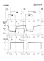
ここで、図2Aに、上記電圧監視部23および充電制御部21によって実現される蓄電デバイス6の充電状態に関する制御のタイミングチャートが示されている。具体的には、図2Aには、上段、中段、下段に、それぞれ、蓄電デバイス6の充放電動作を模式的に示したタイミングチャート、蓄電デバイス6の端子間電圧の推移、電圧監視部23によって判断された蓄電デバイス6の電圧状態の推移が示されており、各段のタイミングチャートは、図2Aにおいて、時間軸が共通となるように配置されており、t1〜t12の12箇所のタイミングがマークされている。
Here, FIG. 2A shows a timing chart of control related to the state of charge of the
ここで、上段の充放電動作に関するタイミングチャートでは、蓄電デバイス6で充電および放電が行われている期間に対応した矢印が記載されている。また、蓄電デバイス6が満充電状態になっている期間、すなわち蓄電デバイス6が負荷3を駆動するのに十分な電力を蓄電している状態となっている期間については、対応する帯状の矩形が記載されている。次に、中段の蓄電デバイス6の端子間電圧の推移については、本発明に係る制御装置2によって蓄電デバイス6の蓄電状態が制御されたときの電圧推移が実線L1で記載されており、その比較例として、従来技術による蓄電状態の制御が行われたときの電圧推移が一点鎖線L2で記載されている。
Here, in the timing chart regarding the charge / discharge operation in the upper stage, arrows corresponding to the period during which the
次に、下段の蓄電デバイス6の電圧状態の推移については、電圧監視部23によって検知されるその端子間電圧が低電圧状態であるか高電圧状態であるかが判断され、その結果が、ハイレベル信号(H信号)又はローレベル信号(L信号)が出力される。具体的には、電圧監視部23は電圧監視用ICチップで構成され、そこには上限監視電圧VHと下限監視電圧VLが設定されており、上限監視電圧VHは下限監視電圧VLより高い相関を有する。そして、蓄電デバイス6の端子間電圧が低電圧状態から電圧上昇に伴って上限監視電圧VH以上となったときに、電圧監視部23の出力がL信号状態に切り替わる。一方で、蓄電デバイス6の端子間電圧が高電圧状態から電圧降下に伴って下限監視電圧VL以下となったときに、電圧監視部23の出力がH信号状態に切り替わる。このように、電圧監視部23によって判断される電圧状態が切り替わる閾値は電圧の変動方向によって異なっており、いわば、当該電圧状態は、ヒステリシスを有する閾値に基づいて行われる。このヒステリシスの大きさ、すなわち上限監視電圧VHと下限監視電圧VLの差分については、後述する。
Next, regarding the transition of the voltage state of the
以上を踏まえて、制御装置2によって実行される蓄電デバイス6の充電状態に関する制御について、図2Aに記載された期間ごとに順次説明する。なお、説明にあたり、タイミングt1以前では、蓄電デバイス6は満充電の状態にあり、電圧監視部23の出力はL信号状態にあるものとする。また、期間t1−t4近傍の端子間電圧の推移の拡大図を、図2Bに示す。図2Bには、図2Aに記載されていないタイミングt2’とt4’が記載されているが、これらのタイミングも含めて以下に順次説明していく。
Based on the above, the control related to the state of charge of the
(1)タイミングt1以前および期間t1−t2
タイミングt1より以前においては、負荷3は駆動されておらず、蓄電デバイス6は満充電状態にあり、故にその端子間電圧は上限監視電圧VHと同じ最大電圧値を示している。なお、このとき電圧監視部23の出力はL信号状態である。ここで、タイミングt1では蓄電デバイス6から負荷3に電力供給(放電)が開始され、負荷3を構成する加速度センサ31、32、無線通信デバイス33を駆動するのに必要な駆動電流が蓄電デバイス6から流れ始める。蓄電デバイス6は幾ばくかの内部抵抗を有することから、この駆動開始時の電流の急峻な立ち上がりとの相関によって蓄電デバイス6の端子間電圧が急激に電圧
降下する。本明細書においては、負荷3を駆動開始した際に流れ始める駆動電流によって引き起こされる蓄電デバイス6の端子間電圧の電圧降下を、「駆動時電圧降下」と称することとする。なお、この駆動時電圧降下は、タイミングt1から後述するタイミングt2’までの間、生じており、その途中のタイミングt2においては当該端子間電圧が下限監視電圧VLを割り込む。なお、期間t1−t2では、電圧監視部23の出力はL信号状態のままである。
(1) Before timing t1 and period t1-t2
Prior to timing t1, the
(2)期間t2−t3
期間t2−t3では、蓄電デバイス6から負荷3への電力供給が引き続き行われ当該負荷3の駆動が継続されている。そのため、途中のタイミングt2’で駆動時電圧降下が完了し、すなわち負荷駆動開始時の急峻な駆動電流の立ち上がり自体は完了した後も、蓄電デバイス6の端子間電圧は駆動時電圧降下に比べては緩やかとなるが時間の経過とともに低下していく。そして、当該期間は、上記の通りタイミングt2で端子間電圧が下限監視電圧VLを割り込んでから所定第一期間ΔtLが経過するまでの期間である。この所定第一期間ΔtLは、電圧監視部23が、当該端子間電圧が下限監視電圧VL以下となっている状態を検知するための閾値であり、当該端子間電圧が下限監視電圧VL以下となっている状態が所定第一期間ΔtL以上続いたときに、すなわちタイミングt3に到達した時点で、電圧監視部23の出力が、L信号状態からH信号状態に切り替わる。
(2) Period t2-t3
In the period t2-t3, the power supply from the
(3)期間t3−t4
タイミングt3以降では、蓄電デバイス6から負荷3への電力供給が引き続き行われ当該負荷3の駆動が継続され、そしてタイミングt4に到達した時点で、当該負荷3の駆動が停止される。そのため、蓄電デバイス6からの放電はタイミングt4で終了し、以てその端子間電圧の降下もタイミングt4で終了することとなる。一方で、上記期間t2−t3において、電圧監視部23の出力が、L信号状態からH信号状態に切り替わったことをもって、タイミングt3以降では振動発電デバイス4から蓄電デバイス6への充電が開始される。そのため、蓄電デバイス6の端子間電圧の降下程度もある程度緩和されている。すなわち、負荷3の駆動により生じた蓄電デバイス6での駆動時電圧降下が下限監視電圧VLを所定期間ΔtL下回ったことをトリガーとして、タイミングt3において蓄電デバイス6への充電が開始されることになる。なお、この蓄電デバイス6への充電は、電圧監視部23の出力がH信号状態で有り続ける間、継続されることになる。
(3) Period t3-t4
After timing t3, the power supply from the
(4)期間t4−t5
上記のとおりタイミングt4の時点で、負荷3の駆動が停止されることから、その駆動に要する駆動電流の蓄電デバイス6から負荷3側への流れが停止されることになる。そのため、期間t1−t2’で生じていた駆動時電圧降下分の電圧上昇がタイミングt4以降で生じる。この電圧上昇の過程において、途中のタイミングt4’で端子間電圧が下限監視電圧VLを通過するが、電圧監視部23の出力には変化はない。なお、期間t1−t4で負荷3を駆動していたため蓄電デバイス6の蓄電電力が消費され、その結果、上記電圧上昇が生じたとしても蓄電デバイス6の端子間電圧は上限監視電圧VHにまでは到達しない。そこで、タイミングt3以降継続されている振動発電デバイス4からの充電により、その端子間電圧の上昇が図られる。この結果、タイミングt5の時点で、当該端子間電圧が上限監視電圧VHに到達するが、その時点でも電圧監視部23の出力はH信号状態のままである。
(4) Period t4-t5
As described above, since the drive of the
(5)期間t5−t6
上記の通りタイミングt5の時点でも振動発電デバイス4から蓄電デバイス6への充電は継続されており、その端子間電圧は上限監視電圧VHである。そして、当該期間は、タイミングt5で端子間電圧が上限監視電圧VHに到達してから所定第二期間ΔtHが経過するまでの期間である。この所定第二期間ΔtHは、電圧監視部23が、当該端子間電圧
が上限監視電圧VH以上となっている状態を検知するための閾値であり、当該端子間電圧が上限監視電圧VH以上となっている状態が所定第二期間ΔtH以上続いたときに、すなわちタイミングt6に到達した時点で、電圧監視部23の出力が、H信号状態からL信号状態に切り替わる。この電圧監視部23の出力の変更をトリガーとして、振動発電デバイス4から蓄電デバイス6への充電が終了される。
(5) Period t5-t6
As described above, charging from the vibration
(6)期間t6−t7、およびそれ以降の期間t7−t12
期間t6−t7は、無線通信モジュール1において、次の負荷動作が始まるまでの待機期間である。したがって、当該期間では蓄電デバイス6の蓄電電力は消費されないため、満充電状態に維持される。なお、次の負荷動作は、予め設定された時間の経過後に開始されてもよく、また、モジュール外部からの指示に従って、もしくはモジュール側の判断に基づいて開始するようにしてもよい。ここで、期間t7−t12については、次の負荷動作に対応したものである。タイミングt7−t12のそれぞれは、上述したタイミングt1−t6に対応するものであり、そのため各タイミングに関する詳細な説明は割愛する。
(6) Period t6-t7 and subsequent period t7-t12
The period t6-t7 is a waiting period until the next load operation starts in the wireless communication module 1. Therefore, since the stored power of the
このように、本発明に係る無線通信モジュール1では、ヒステリシスを有する二つの電圧閾値、下限監視電圧VLと上限監視電圧VHが設定された電圧監視部23による電圧監視の結果に基づいて、蓄電デバイス6の充電タイミングが制御される。すなわち、充電を開始するための閾値と充電を停止するための閾値を異なるように設定し、そして負荷3を駆動したときに生じる駆動時電圧降下によって蓄電デバイス6の端子間電圧が閾値となる下限監視電圧VLを下回ったことをもって、蓄電デバイス6の充電開始のトリガーとする構成である。
Thus, in the wireless communication module 1 according to the present invention, the power storage device is based on the result of voltage monitoring by the
負荷3の駆動に要する電力量が小さい場合は、駆動の前後の蓄電デバイス6の端子間電圧の差は、さほど大きくならない場合がある。特に、無線通信モジュール1の利便性を高めるために、そこに搭載される各負荷要素の小型化が図られる昨今の流れでは、一度の負荷動作に要する消費エネルギーは極めて小さいものである。たとえば、図2Aに示す例で、上限監視電圧を3.57V、下限監視電圧を3.4Vとし、蓄電デバイス6の容量を0.033F、負荷3の一連の動作(上述した加速度センサ31、32、無線通信デバイス33の駆動動作)に要する駆動エネルギーΔEを0.002Jとすると、負荷駆動終了時の端子間電圧Vendは、3.55Vとなる。このときの蓄電デバイス6の端子間電圧の推移を、図2Aの中段に一点鎖線L2で示す。この場合の負荷駆動の前後での電圧差は0.02Vに過ぎず、電圧検出の誤差やノイズの影響を踏まえると0.02Vの電圧差を的確に検出することは容易ではないと言える。
When the amount of power required for driving the
一方で、負荷3を駆動する過程において、負荷3に供給される駆動電圧は、その駆動を保証するための駆動電圧Vmin(図2A、図2Bを参照)を常に上回っている必要がある。しかし、仮に負荷3を一度駆動した後に蓄電デバイス6の充電が行われなかった状態で、更に負荷3の駆動が行われると、図2Aの一点鎖線L2に示すように、二度目の負荷駆動開始時に生じる駆動時電圧降下によって、蓄電デバイス6の端子間電圧が駆動電圧Vminを下回ってしまい、負荷3の安定的な駆動が保たれないおそれがある。
On the other hand, in the process of driving the
しかし、本発明の無線通信モジュール1では、上述した充電に関する構成を有することから、負荷3の駆動による蓄電コンデンサ6の蓄電電力の消費、換言すれば、蓄電コンデンサ6が充電が必要な状態になっていることを、駆動時電圧降下による端子間電圧の電圧状態に基づいて検出することが可能となる。したがって、図2Aの実線L1で示すように、負荷3を駆動している過程において、蓄電デバイス6の端子間電圧が駆動電圧Vminを下回ってしまうことを確実に回避することが可能となる。特に、負荷3の駆動が連続的に繰り返される場合には、その駆動を定常的に実現するために蓄電デバイス6の充電タイミングの決定は極めて重要である。
However, since the wireless communication module 1 according to the present invention has the above-described configuration related to charging, the power consumption of the
ここで、蓄電デバイス6の満充電時の端子間電圧VHと、充電開始のトリガーとなる閾値電圧VLとの差分VH−VLは、以下の式1を満たすように決定することが好ましい。
VH−VL<Vd−ΔVn ・・・(式1)
Vd:駆動時電圧降下
ΔVn:ノイズ等による電圧変動を吸収するマージン項
このような差分VH−VLの設定を行うことで、負荷3が一連の動作(上述した加速度センサ31、32、無線通信デバイス33の駆動動作)を行う毎に、図2Aに示すように蓄電デバイス6の充電開始のトリガーが発生することになり、新たな負荷動作が開始される時点には蓄電デバイス6は満充電状態にされているため、無線通信モジュール1の安定的な連続動作を確保することが可能となる。
Here, the difference VH−VL between the inter-terminal voltage VH when the
VH−VL <Vd−ΔVn (Expression 1)
Vd: Voltage drop during driving ΔVn: Margin term for absorbing voltage fluctuations due to noise etc. By setting such a difference VH−VL, the
また、上記実施形態では、電圧監視部23が蓄電デバイス6の電圧状態を監視する際に、その端子間電圧が下限監視電圧VL以下となって直ちに、もしく上限監視電圧VH以上となって直ちに電圧状態を示すH信号もしくはL信号を切り替えずに、所定第一期間ΔtLもしくは所定第二期間ΔtHの経過を待って信号の切り替えを行う構成を採用している。このように端子間電圧が一定の期間、下限監視電圧VL以下となること、もしくは上限監視電圧VH以上となることを電圧状態の信号切替の要件とすることで、ノイズ等の外乱によって端子間電圧が瞬時に乱れたときに、不用意な充電の開始もしくは充電の停止が実行されるのを回避することができ、以て安定的な蓄電デバイス6の充電制御、ひいては負荷3の安定的な駆動を確保することができる。
Moreover, in the said embodiment, when the
なお、所定第一期間ΔtLについては、以下の式2を満たすように決定することが好ましい。
ΔtL<ΔT1+ΔT2 ・・・(式2)
ΔT1:駆動時電圧降下により端子間電圧が下限監視電圧VLを割り込んだタイミングt2から、駆動時電圧降下が完了したタイミングt2’までの時間
ΔT2:上記t2’から、負荷の駆動停止により駆動時電圧降下が解消することで端子間電圧が急上昇し下限監視電圧VLを超えたタイミングt4’までの時間
このように所定第一期間ΔtLを設定することで、上記のようにノイズ等の外乱の影響を排除しながら安定的な負荷3の駆動を確保することができる。また、所定第二期間ΔtHの最大値については、負荷3の連続動作が妨げられない程度に、すなわち図2Aで示す期間t5−t7がいたずらに長くならない程度に設定するのが好ましい。以上を踏まえ、例えば、所定第一期間ΔtL、所定第二期間ΔtHは、それぞれ約30μ秒に設定することができる。
The predetermined first period ΔtL is preferably determined so as to satisfy the
ΔtL <ΔT1 + ΔT2 (Formula 2)
ΔT1: Time from the timing t2 when the voltage between the terminals interrupts the lower limit monitoring voltage VL due to the voltage drop during driving to the timing t2 ′ when the voltage drop during driving is completed ΔT2: the voltage during driving due to the load stoppage from the above t2 ′ The time until the timing t4 ′ when the voltage between the terminals suddenly increases and exceeds the lower limit monitoring voltage VL by eliminating the drop By setting the predetermined first period ΔtL in this way, the influence of disturbances such as noise can be reduced as described above. Stable drive of the
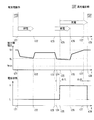
<変形例1>
図3に本発明に係る無線通信モジュール1に含まれる制御装置2による蓄電デバイス6の充電制御の変形例を示す。図3に示す例では、図2Aに示す例と異なり、負荷3が複数の動作(本例では2回の動作)を行った後に蓄電デバイス6の充電制御が行われる。以下、その充電制御の概略を説明する。なお、本変形例で行われる負荷3の駆動については、その一回当たりの駆動に要する電力量は、例えば駆動する加速度センサの台数を1台に制限する等して、図2Aに示した例と比べて小さいものとする。
<Modification 1>
FIG. 3 shows a modification of the charging control of the
(1)期間t21−t22
当該期間では、負荷3の一回目の駆動が行われる。この期間では、駆動時電圧降下を含めて、蓄電デバイス6の端子間電圧は下限監視電圧VL以下とはならない。
(2)期間t22−t23
当該期間では負荷3の駆動が停止されるが、上記のとおり端子間電圧が下限監視電圧VL以下とはならないことから、振動発電デバイス4からの充電も行われない。したがって
、当該期間での端子間電圧は、電圧VHに戻らずに駆動時電圧降下が解消した状態での電圧で維持される。
なお、上述までの期間においては、電圧監視部23については、端子間電圧が所定第一時間ΔtLだけ下限監視電圧VL以下とはならないことから、その出力はL信号状態のままである。
(1) Period t21-t22
During the period, the first driving of the
(2) Period t22-t23
During the period, the driving of the
In the period up to the above, the
(3)期間t23−t24
タイミングt23において、二回目の負荷3の駆動が開始される。そのため、タイミングt23以降で、端子間電圧が駆動時電圧降下によって大きく低下し、タイミングt24の時点で下限監視電圧VL以下となる。
(4)期間t24−t25
当該期間は、タイミングt24以降、所定第一期間ΔtLが経過するまでの期間である。当該期間において、端子間電圧は下限監視電圧VLを下回った状態にある。したがって、タイミングt25に到達した時点で、電圧監視部23の出力が、L信号状態からH信号状態に切り替えられ、蓄電デバイス6の充電開始のトリガーが生成されることになる。
(5)期間t25−t26
当該期間では蓄電デバイス6の充電が継続されるとともに、タイミングt26の時点で負荷3の駆動が停止される。
(6)期間t26−t27
上記のとおり、タイミングt26で負荷3の駆動が停止されることから、当該期間では駆動時電圧降下が解消される。そのため、端子間電圧が急激に上昇し、更に蓄電デバイス6への充電が継続される。そして、タイミングt27の時点で端子間電圧が上限監視電圧VHに到達する。
(7)期間t27−t28
当該期間は、タイミングt27以降、所定第二期間ΔtHが経過するまでの期間である。当該期間において、初めは端子間電圧は上限監視電圧VHとなった状態にあり、タイミングt28に到達した時点で、電圧監視部23の出力が、H信号状態からL信号状態に切り替えられ、蓄電デバイス6の充電終了のトリガーが生成されることになる。
(3) Period t23-t24
At timing t23, the second driving of the
(4) Period t24-t25
This period is a period from the timing t24 until the predetermined first period ΔtL elapses. During this period, the inter-terminal voltage is below the lower limit monitoring voltage VL. Therefore, when the timing t25 is reached, the output of the
(5) Period t25-t26
During this period, charging of the
(6) Period t26-t27
As described above, since the driving of the
(7) Period t27-t28
This period is a period from the timing t27 until the predetermined second period ΔtH elapses. In this period, the inter-terminal voltage is initially in the state of the upper limit monitoring voltage VH, and when the timing t28 is reached, the output of the
このように複数回の負荷3の駆動が行われた後に、駆動時電圧降下に基づいて蓄電デバイス6の充電制御が開始されるように構成しても構わない。ただし、このような場合では、一回当たりの負荷駆動における端子間電圧の変動幅が比較的小さいことから、複数回の動作を行う間において、当該端子間電圧が動作電圧Vminを下回らないことが求められる。また、本変形例に係る構成では、いわば二回分の負荷駆動で消費した電力を一度の充電制御(期間t25−t28までの充電制御)で補充することになるため、一回の負荷駆動ごとに充電制御を行う場合と比べて満充電状態にするまでの充電時間が長期化する可能性がある。そのため、想定する負荷駆動のパターンに支障を可及的に及ぼさないようにする観点に立てば、図2Aに示すように、一回の負荷3の動作ごとに充電制御が行われるように、VLの値を調整するのが好ましいと言える。
In this way, after the
<変形例2>
図4に本発明に係る無線通信モジュール1の変形例を示す。図4に示す例では、図1に示す例と異なり、負荷3に、加速度センサ31、32および無線通信デバイス33の他に、ダミー負荷回路34、35が含まれる構成となっている。このダミー負荷回路34、35は、加速度センサ31等と異なり、特定のデータの取得や取得データの外部への無線通信等を行う機能的な負荷要素ではなく、蓄電デバイス6から供給される電力を消費するための電力消費回路として負荷要素である。消費電力能力は、ダミー負荷回路34の方がダミー負荷回路35よりも小さいものとする。そして、ダミー負荷回路34、35は、それぞれスイッチ36、37のON、OFFによって、蓄電デバイス6からの電力供給が可能となるように接続、又は遮断される。
<
FIG. 4 shows a modification of the wireless communication module 1 according to the present invention. In the example illustrated in FIG. 4, unlike the example illustrated in FIG. 1, the
このように構成される無線通信モジュール1では、負荷3の駆動に要する電力量が小さく、特に駆動時電圧降下が小さい場合であっても、確実に蓄電デバイス6の充電開始のタイミングを制御することが可能となる。例えば、図3に示した、加速度センサ31のみが駆動されるような負荷3の駆動時電圧降下が小さい場合においては、一回目の負荷駆動では、蓄電デバイス6の端子間電圧が下限監視電圧VL以下とならないため蓄電デバイス6の充電制御は開始されない。しかし、本変形例では、加速度センサ31の駆動とともにダミー負荷回路34への電力供給を行うようにすることで、負荷3全体の駆動に要する電力を増加させ、駆動時電圧降下を大きくすることが可能となる。その結果、小さな負荷要素を駆動させるような場合であっても、その一回の駆動ごとに、蓄電デバイス6の充電を適切なタイミングで実行することが可能となる。このようなダミー負荷回路34への電力供給は、本発明に係る負荷の強制動作に相当する。
In the wireless communication module 1 configured as described above, even when the amount of power required for driving the
また、負荷の強制動作の別の例として、負荷3を駆動させる前に、蓄電デバイス6を確実に満充電状態としておくためにダミー負荷回路35のみを駆動させるようにしてもよい。何らかの理由で負荷3の駆動中の動作安定性をより確実なものとするために、その駆動直前にダミー負荷回路35への電力供給を行う。ダミー負荷回路35は、その消費電力能力から蓄電デバイス6の充電制御を開始するためのトリガーを発生させるのに十分な駆動時電圧降下を生じさせる負荷要素である。このようなダミー負荷回路35を設けておくことで、負荷3が比較的消費電力が大きい動作を行う場合であっても、事前に蓄電デバイス6を満充電状態にしておくことが可能となるため、安定した負荷動作を確保することができる。
As another example of the forced load operation, only the
本発明に係る制御装置2および無線通信モジュール1の実施例を以下に示す。
上限監視電圧VH:3.57V
下限監視電圧VL:3.4V
蓄電デバイス6の内部抵抗:50Ω
このとき、負荷3の駆動時電流を10mAとなるように負荷3内の負荷要素(加速度センサ等)を選定する。そうすると、駆動時電圧降下は0.5Vとなり、電圧降下後の蓄電デバイス6の端子間電圧が3.07Vとなるため、外乱による端子間電圧の変動を考慮しても安定的な負荷3の駆動が期待できる。
Examples of the
Upper limit monitoring voltage VH: 3.57V
Lower limit monitoring voltage VL: 3.4V
Internal resistance of electricity storage device 6: 50Ω
At this time, the load element (acceleration sensor or the like) in the
なお、駆動電流が小さすぎると十分な駆動時電圧降下を発生できないことを踏まえて、駆動時電流の最小値は、(3.57−3.4)/50=3.4mAとする(便宜的に、外乱による電圧変動は考慮していない。)。一方で、駆動電流が大きすぎると、端子間電圧が負荷3の駆動電圧Vminを下回ってしまうため、好ましくない。そこで、駆動電圧Vminを2.0Vとすると、(3.57−2.0)/50=31.4mAを駆動電流の最大値とする。
In view of the fact that a sufficient drive voltage drop cannot be generated if the drive current is too small, the minimum value of the drive current is (3.57-3.4) /50=3.4 mA (for convenience) In addition, voltage fluctuations due to disturbance are not considered.) On the other hand, if the drive current is too large, the voltage between the terminals is less than the drive voltage Vmin of the
また、負荷3を構成する負荷要素の具体例を以下に示す。具体的には、無線通信デバイスとして二種類の例を表1に示し、加速度センサを含めたセンサ類として6種類の例を表2に示す。各負荷要素によって生じる駆動時電圧降下の総和が、負荷3全体の電圧降下量として現れて蓄電センサ6の充電制御の開始のトリガーを生成することになる。したがって、使用する無線通信デバイスやセンサの種類、数を考慮して、制御装置2における上限監視電圧VHおよび下限監視電圧VLを設定すればよい。

1・・・・無線通信モジュール
2・・・・制御装置
3・・・・負荷
4・・・・振動発電デバイス
6・・・・蓄電デバイス
21・・・・充電制御部
22・・・・放電制御部
23・・・・電圧監視部
34、35・・・・ダミー負荷回路
DESCRIPTION OF SYMBOLS 1 ....
Claims (9)
前記蓄電部の端子間電圧が所定上限電圧以上であると該蓄電部は満充電状態にあると判断し、該蓄電部の端子間電圧が該所定上限電圧より低い所定下限電圧以下であると充電が必要と判断する電圧監視部と、
前記蓄電部の端子間電圧に基づいて、前記蓄電部への充電を制御する充電制御部と、を備え、
前記負荷は、前記蓄電部からの電力供給によって単一の動作又は複数の動作からなる所定の動作を実行するものであって、
前記所定上限電圧と前記所定下限電圧との差分は、前記負荷が前記所定の動作を行っている際に生じる前記蓄電部内での電圧降下によって、該所定上限電圧にある該蓄電部の端子間電圧が、該所定下限電圧以下となるように設定され、
更に、前記負荷に、前記所定の動作以外の所定の強制動作を行わせて、該所定の動作の際より多くの電流を該負荷に消費させる強制駆動部を備える、前記蓄電部への充電状態を制御する充電制御装置であって、
前記強制駆動部が前記負荷に前記所定の強制動作を行わせたときに該蓄電部内の抵抗成分と負荷電流とに起因して該蓄電部内で生じる電圧降下により該蓄電部の端子間電圧が前記所定下限電圧以下になることで、前記電圧監視部が前記蓄電部の充電が必要と判断すると、前記充電制御部は、前記電源から前記蓄電部への充電を行い該蓄電部の端子間電圧を前記所定上限電圧以上とする、
充電制御装置。 A power storage unit that stores power supplied from a power source and supplies the stored power to a load;
When the voltage between the terminals of the power storage unit is equal to or higher than a predetermined upper limit voltage, the power storage unit is determined to be fully charged, and charged when the voltage between the terminals of the power storage unit is equal to or lower than a predetermined lower limit voltage lower than the predetermined upper limit voltage. A voltage monitoring unit that determines that the
A charge control unit that controls charging of the power storage unit based on a voltage between terminals of the power storage unit ,
The load executes a predetermined operation consisting of a single operation or a plurality of operations by supplying power from the power storage unit,
The difference between the predetermined upper limit voltage and the predetermined lower limit voltage is the voltage across the terminals of the power storage unit at the predetermined upper limit voltage due to a voltage drop in the power storage unit that occurs when the load is performing the predetermined operation. Is set to be equal to or lower than the predetermined lower limit voltage,
Furthermore, the state of charge to the power storage unit is provided with a forcible driving unit that causes the load to perform a predetermined forcing operation other than the predetermined operation and consume more current during the predetermined operation. A charge control device for controlling
When the forced drive unit causes the load to perform the predetermined forced operation , a voltage drop generated in the power storage unit due to a resistance component in the power storage unit and a load current causes the voltage between the terminals of the power storage unit to be When the voltage monitoring unit determines that charging of the power storage unit is necessary because the voltage monitoring unit is equal to or lower than a predetermined lower limit voltage, the charge control unit charges the power storage unit from the power source and determines the voltage across the terminals of the power storage unit. More than the predetermined upper limit voltage,
Charge control device.
請求項1に記載の充電制御装置。 The voltage between the terminals of the power storage unit is maintained at or above a predetermined drive voltage necessary for driving the load while the load is performing the predetermined operation.
The charge control device according to claim 1 .
請求項1又は請求項2に記載の充電制御装置。 The charge control unit charges at least a difference between the voltage between the terminals and the predetermined upper limit voltage when the voltage drop in the power storage unit is canceled and the voltage between the terminals is recovered by stopping the driving load. Control the power supply from the power source,
The charge control device according to claim 1 or 2 .
請求項1から請求項3の何れか一項に記載の充電制御装置。 When the voltage monitoring unit is in a state where the voltage between the terminals of the power storage unit has become equal to or lower than the predetermined lower limit voltage due to a voltage drop in the power storage unit when the load is being driven, Determining that charging of the power storage unit is necessary;
The charge control device according to any one of claims 1 to 3 .
前記蓄電部に電力を供給する電源と、
前記蓄電部から駆動電力が供給される負荷と、
を備える、駆動負荷モジュール。 The charge control device according to any one of claims 1 to 4 ,
A power source for supplying power to the power storage unit;
A load to which driving power is supplied from the power storage unit;
A drive load module comprising:
前記駆動負荷モジュールの周囲の所定の環境パラメータを検出する一又は複数のセンサと、
前記一又は複数のセンサの検出値を、前記駆動負荷モジュールとは離れて位置する所定の受信部へ無線で送信する無線送信部と、
を含む、請求項5に記載の駆動負荷モジュール。 The load is
One or more sensors for detecting predetermined environmental parameters around the drive load module;
A wireless transmission unit that wirelessly transmits detection values of the one or more sensors to a predetermined reception unit located away from the drive load module;
The drive load module according to claim 5, comprising:
請求項5又は請求項6に記載の駆動負荷モジュール。 The power source includes a vibration power generation apparatus that converts external vibration energy into power or a solar power generation apparatus that performs solar power generation.
The driving load module according to claim 5 or 6 .
前記蓄電部は、前記一の環境型発電装置および前記電力供給装置から選択的に、もしくは該一の環境型発電装置および該電力供給装置から同時に電力供給される、
請求項5又は請求項6に記載の駆動負荷モジュール。 The power source includes one environmental power generation device that converts environmental energy into power, and further includes at least a power supply device that includes another environmental power generation device or a power supply device that can be discharged to the outside.
The power storage unit is supplied with power selectively from the one environmental power generation device and the power supply device or simultaneously from the one environmental power generation device and the power supply device.
The driving load module according to claim 5 or 6 .
前記蓄電部の端子間電圧が所定上限電圧以上であると該蓄電部は満充電状態にあると判断し、該蓄電部の端子間電圧が該所定上限電圧より低い所定下限電圧以下であると充電が必要と判断する判断基準に従い、前記充電状態の制御が行われ、
前記負荷は、前記蓄電部からの電力供給によって単一の動作又は複数の動作からなる所定の動作を実行するものであって、
前記所定上限電圧と前記所定下限電圧との差分は、前記負荷が前記所定の動作を行っている際に生じる前記蓄電部内での電圧降下によって、該所定上限電圧にある該蓄電部の端子間電圧が、該所定下限電圧以下となるように設定され、
前記負荷に、前記所定の動作以外の所定の強制動作を行わせて、該所定の動作の際より多くの電流を該負荷に消費させたときに該蓄電部内の抵抗成分と負荷電流とに起因して該蓄電部内で生じる電圧降下により該蓄電部の端子間電圧が前記所定下限電圧以下になることを検出するステップと、
前記蓄電部の端子間電圧が前記所定下限電圧以下になると、前記電源から前記蓄電部への充電を行い該蓄電部の端子間電圧を前記所定上限電圧以上とするステップと、
を含んでなる充電制御方法。 A charge control method for storing power supplied from a power source and controlling a charge state of a power storage unit that supplies stored power to a load,
When the voltage between the terminals of the power storage unit is equal to or higher than a predetermined upper limit voltage, the power storage unit is determined to be fully charged, and charged when the voltage between the terminals of the power storage unit is equal to or lower than a predetermined lower limit voltage lower than the predetermined upper limit voltage. The charging state is controlled in accordance with a determination criterion that determines that is necessary,
The load executes a predetermined operation consisting of a single operation or a plurality of operations by supplying power from the power storage unit,
The difference between the predetermined upper limit voltage and the predetermined lower limit voltage is the voltage across the terminals of the power storage unit at the predetermined upper limit voltage due to a voltage drop in the power storage unit that occurs when the load is performing the predetermined operation. Is set to be equal to or lower than the predetermined lower limit voltage,
When the load is caused to perform a predetermined forced operation other than the predetermined operation, and when the load consumes more current than the predetermined operation, the load is caused by the resistance component and the load current in the power storage unit. Detecting that the voltage between the terminals of the power storage unit is equal to or lower than the predetermined lower limit voltage due to a voltage drop generated in the power storage unit;
When the voltage between the terminals of the power storage unit is equal to or lower than the predetermined lower limit voltage, charging the power storage unit from the power source to set the voltage between the terminals of the power storage unit to be equal to or higher than the predetermined upper limit voltage;
A charge control method comprising:
Priority Applications (4)
| Application Number | Priority Date | Filing Date | Title |
|---|---|---|---|
| JP2011056380A JP5408162B2 (en) | 2011-03-15 | 2011-03-15 | Charge control device and drive load module |
| PCT/JP2011/056962 WO2012124156A1 (en) | 2011-03-15 | 2011-03-23 | Charge control device and drive load module |
| GB1315390.3A GB2502479B (en) | 2011-03-15 | 2011-03-23 | Charge control device and drive load module |
| US14/004,766 US9484764B2 (en) | 2011-03-15 | 2011-03-23 | Charge control device and drive load module |
Applications Claiming Priority (1)
| Application Number | Priority Date | Filing Date | Title |
|---|---|---|---|
| JP2011056380A JP5408162B2 (en) | 2011-03-15 | 2011-03-15 | Charge control device and drive load module |
Publications (2)
| Publication Number | Publication Date |
|---|---|
| JP2012196001A JP2012196001A (en) | 2012-10-11 |
| JP5408162B2 true JP5408162B2 (en) | 2014-02-05 |
Family
ID=46830264
Family Applications (1)
| Application Number | Title | Priority Date | Filing Date |
|---|---|---|---|
| JP2011056380A Expired - Fee Related JP5408162B2 (en) | 2011-03-15 | 2011-03-15 | Charge control device and drive load module |
Country Status (4)
| Country | Link |
|---|---|
| US (1) | US9484764B2 (en) |
| JP (1) | JP5408162B2 (en) |
| GB (1) | GB2502479B (en) |
| WO (1) | WO2012124156A1 (en) |
Families Citing this family (8)
| Publication number | Priority date | Publication date | Assignee | Title |
|---|---|---|---|---|
| JPWO2015015527A1 (en) * | 2013-07-29 | 2017-03-02 | パナソニックIpマネジメント株式会社 | Power supply control device |
| JP6239897B2 (en) * | 2013-08-09 | 2017-11-29 | Kyb株式会社 | Sensor device |
| US20160324077A1 (en) * | 2015-05-05 | 2016-11-10 | Helical Holdings, Llc | Portable hydroponic greenhouse assembly and method of using same |
| JP6790071B2 (en) * | 2016-03-25 | 2020-11-25 | シャープ株式会社 | Power generation system, power conditioner, power control device, power control method and power control program |
| KR102433146B1 (en) | 2017-09-28 | 2022-08-17 | 주식회사 엘지에너지솔루션 | Method for preventing swelling of battery cell and battery pack using the same |
| JP7306212B2 (en) * | 2019-10-17 | 2023-07-11 | 日本ゼオン株式会社 | power supply |
| JP7414679B2 (en) | 2020-09-16 | 2024-01-16 | 株式会社東芝 | Condition monitoring system, condition monitoring program and controller |
| CN112744101B (en) * | 2020-12-25 | 2023-02-17 | 中国第一汽车股份有限公司 | Charging and discharging control system and method and vehicle |
Family Cites Families (10)
| Publication number | Priority date | Publication date | Assignee | Title |
|---|---|---|---|---|
| JPS6154820A (en) * | 1984-08-23 | 1986-03-19 | シャープ株式会社 | Dc/ac converter of photogenerator system |
| JPH06323154A (en) | 1993-05-11 | 1994-11-22 | Isuzu Motors Ltd | Power control device for vehicle |
| JPH1066271A (en) * | 1996-08-12 | 1998-03-06 | Toshiba Home Technol Corp | Charging controller and electric thermos bottle equipped with the charging controller |
| US6301198B1 (en) | 1997-12-11 | 2001-10-09 | Citizen Watch Co., Ltd. | Electronic timepiece |
| JP2004236381A (en) | 2003-01-28 | 2004-08-19 | Honda Motor Co Ltd | Charge/discharge controller for storage battery, and charge/discharge controller for storage battery of vehicle |
| JP2005242441A (en) * | 2004-02-24 | 2005-09-08 | Tateyama Kagaku Kogyo Kk | Event detection system |
| CA2597145C (en) * | 2005-04-28 | 2015-03-03 | Rosemount Inc. | Charging system for field devices |
| EP1986306B1 (en) * | 2006-01-27 | 2014-05-14 | Sharp Kabushiki Kaisha | Power supply system |
| US7671567B2 (en) * | 2007-06-15 | 2010-03-02 | Tesla Motors, Inc. | Multi-mode charging system for an electric vehicle |
| US20110193518A1 (en) * | 2010-02-10 | 2011-08-11 | James Wright | Battery override |
-
2011
- 2011-03-15 JP JP2011056380A patent/JP5408162B2/en not_active Expired - Fee Related
- 2011-03-23 WO PCT/JP2011/056962 patent/WO2012124156A1/en active Application Filing
- 2011-03-23 GB GB1315390.3A patent/GB2502479B/en active Active
- 2011-03-23 US US14/004,766 patent/US9484764B2/en active Active
Also Published As
| Publication number | Publication date |
|---|---|
| US9484764B2 (en) | 2016-11-01 |
| GB2502479B (en) | 2017-04-12 |
| WO2012124156A1 (en) | 2012-09-20 |
| US20140002029A1 (en) | 2014-01-02 |
| JP2012196001A (en) | 2012-10-11 |
| GB201315390D0 (en) | 2013-10-16 |
| GB2502479A (en) | 2013-11-27 |
Similar Documents
| Publication | Publication Date | Title |
|---|---|---|
| JP5408162B2 (en) | Charge control device and drive load module | |
| JP5806413B2 (en) | Power supply control device and control method for power supply control device | |
| JP5310662B2 (en) | Voltage conversion circuit and electronic device | |
| JP6018980B2 (en) | Free standing power system | |
| JPWO2015115654A1 (en) | Sensor node and sensor node control method | |
| JP5961121B2 (en) | Battery degradation measuring apparatus and method | |
| JP6007385B2 (en) | Power storage device, control method therefor, and power supply device | |
| JP5790197B2 (en) | Image forming apparatus and power supply control method | |
| TW201822423A (en) | Energy harvest system and control method thereof | |
| JP5874505B2 (en) | Vibration energy detection device, vibration energy detection system | |
| JP5960641B2 (en) | Charger | |
| US9306452B2 (en) | Multiple power path management with micro-energy harvesting | |
| CN111480279A (en) | Hybrid power supply control system for supplying electrical power to a load, and corresponding method and sensor comprising such a control system | |
| JP6357966B2 (en) | Power supply control device and electronic device | |
| EP2808975B1 (en) | Inductive power transmission device | |
| US8773083B2 (en) | Detection of insufficient current sourcing capability of supplied power | |
| JP2011079399A (en) | Power supply control device for vehicle and power supply device for vehicle | |
| CN203104016U (en) | Power supply circuit of remote controller and air-conditioning system having the same | |
| JP2016226130A (en) | Charging device, electronic device, and charging method | |
| CN101789634B (en) | Solar power supply circuit of vehicle-mounted automatic electronic charging unit | |
| JP2015106999A (en) | Power supply facility and operational method thereof | |
| JP2013233008A (en) | Power supply apparatus | |
| CN200987139Y (en) | Pulsewidth controllable automobile voltage regulator | |
| JP2010098827A (en) | Charge/discharge control method, charge/discharge controller, and self-supporting power supply system | |
| KR101418174B1 (en) | Apparatus of Operation shutdown circuit using regulator for Battery management system |
Legal Events
| Date | Code | Title | Description |
|---|---|---|---|
| A131 | Notification of reasons for refusal |
Free format text: JAPANESE INTERMEDIATE CODE: A131 Effective date: 20130723 |
|
| A521 | Request for written amendment filed |
Free format text: JAPANESE INTERMEDIATE CODE: A523 Effective date: 20130918 |
|
| TRDD | Decision of grant or rejection written | ||
| A01 | Written decision to grant a patent or to grant a registration (utility model) |
Free format text: JAPANESE INTERMEDIATE CODE: A01 Effective date: 20131008 |
|
| A61 | First payment of annual fees (during grant procedure) |
Free format text: JAPANESE INTERMEDIATE CODE: A61 Effective date: 20131021 |
|
| R150 | Certificate of patent or registration of utility model |
Ref document number: 5408162 Country of ref document: JP Free format text: JAPANESE INTERMEDIATE CODE: R150 |
|
| LAPS | Cancellation because of no payment of annual fees |