EP4269155A1 - System for remote controls and displays for an industrial vehicle - Google Patents
System for remote controls and displays for an industrial vehicle Download PDFInfo
- Publication number
- EP4269155A1 EP4269155A1 EP22169916.8A EP22169916A EP4269155A1 EP 4269155 A1 EP4269155 A1 EP 4269155A1 EP 22169916 A EP22169916 A EP 22169916A EP 4269155 A1 EP4269155 A1 EP 4269155A1
- Authority
- EP
- European Patent Office
- Prior art keywords
- remote control
- control device
- person
- display
- functions
- Prior art date
- Legal status (The legal status is an assumption and is not a legal conclusion. Google has not performed a legal analysis and makes no representation as to the accuracy of the status listed.)
- Pending
Links
- 230000006870 function Effects 0.000 claims abstract description 50
- 230000005540 biological transmission Effects 0.000 claims abstract description 12
- 238000000034 method Methods 0.000 claims description 13
- 238000001514 detection method Methods 0.000 claims description 6
- 238000005516 engineering process Methods 0.000 claims description 4
- 238000004891 communication Methods 0.000 description 3
- 230000033001 locomotion Effects 0.000 description 3
- 239000000725 suspension Substances 0.000 description 3
- 230000005484 gravity Effects 0.000 description 2
- 230000000007 visual effect Effects 0.000 description 2
- 238000004378 air conditioning Methods 0.000 description 1
- 238000010586 diagram Methods 0.000 description 1
- 230000004044 response Effects 0.000 description 1
- 230000006641 stabilisation Effects 0.000 description 1
- 238000011105 stabilization Methods 0.000 description 1
- 230000001960 triggered effect Effects 0.000 description 1
Images

Classifications
-
- G—PHYSICS
- G06—COMPUTING; CALCULATING OR COUNTING
- G06F—ELECTRIC DIGITAL DATA PROCESSING
- G06F3/00—Input arrangements for transferring data to be processed into a form capable of being handled by the computer; Output arrangements for transferring data from processing unit to output unit, e.g. interface arrangements
- G06F3/01—Input arrangements or combined input and output arrangements for interaction between user and computer
- G06F3/048—Interaction techniques based on graphical user interfaces [GUI]
- G06F3/0484—Interaction techniques based on graphical user interfaces [GUI] for the control of specific functions or operations, e.g. selecting or manipulating an object, an image or a displayed text element, setting a parameter value or selecting a range
- G06F3/04842—Selection of displayed objects or displayed text elements
-
- B60K35/60—
-
- B60K35/10—
-
- B60K35/22—
-
- B60K35/25—
-
- B60K35/26—
-
- B60K35/28—
-
- B60K35/65—
-
- B60K35/80—
-
- B60K35/85—
-
- B—PERFORMING OPERATIONS; TRANSPORTING
- B60—VEHICLES IN GENERAL
- B60N—SEATS SPECIALLY ADAPTED FOR VEHICLES; VEHICLE PASSENGER ACCOMMODATION NOT OTHERWISE PROVIDED FOR
- B60N2/00—Seats specially adapted for vehicles; Arrangement or mounting of seats in vehicles
- B60N2/002—Seats provided with an occupancy detection means mounted therein or thereon
-
- G—PHYSICS
- G06—COMPUTING; CALCULATING OR COUNTING
- G06T—IMAGE DATA PROCESSING OR GENERATION, IN GENERAL
- G06T7/00—Image analysis
- G06T7/70—Determining position or orientation of objects or cameras
-
- G—PHYSICS
- G08—SIGNALLING
- G08C—TRANSMISSION SYSTEMS FOR MEASURED VALUES, CONTROL OR SIMILAR SIGNALS
- G08C17/00—Arrangements for transmitting signals characterised by the use of a wireless electrical link
- G08C17/02—Arrangements for transmitting signals characterised by the use of a wireless electrical link using a radio link
-
- B60K2360/119—
-
- B60K2360/1438—
-
- B60K2360/171—
-
- B60K2360/573—
-
- B60K2360/589—
-
- B60K2360/741—
-
- B—PERFORMING OPERATIONS; TRANSPORTING
- B60—VEHICLES IN GENERAL
- B60Y—INDEXING SCHEME RELATING TO ASPECTS CROSS-CUTTING VEHICLE TECHNOLOGY
- B60Y2200/00—Type of vehicle
- B60Y2200/10—Road Vehicles
- B60Y2200/14—Trucks; Load vehicles, Busses
-
- G—PHYSICS
- G06—COMPUTING; CALCULATING OR COUNTING
- G06T—IMAGE DATA PROCESSING OR GENERATION, IN GENERAL
- G06T2207/00—Indexing scheme for image analysis or image enhancement
- G06T2207/30—Subject of image; Context of image processing
- G06T2207/30196—Human being; Person
-
- G—PHYSICS
- G06—COMPUTING; CALCULATING OR COUNTING
- G06T—IMAGE DATA PROCESSING OR GENERATION, IN GENERAL
- G06T2207/00—Indexing scheme for image analysis or image enhancement
- G06T2207/30—Subject of image; Context of image processing
- G06T2207/30248—Vehicle exterior or interior
Definitions
- This disclosure relates to a system for remote controls and displays for an industrial vehicle.
- a truck may have a remote control for electrical controlled suspension (RCECS).
- RECS electrical controlled suspension
- This remote control is for example placed near the driver's seat.
- This remote control is connected in most cases by wire to the truck. This ensures a good connection, and the remote control cannot get lost.
- the truck comprises a bunk area
- this area may also comprise a living environment control module (LECM) which is usually connected by wire to the truck.
- LCM living environment control module
- a third remote control is often foreseen by a bodybuilder and it controls specific functions corresponding to the specific equipment provided by the body builder.
- Specific functions of bodybuilder can include the following without any limitation purpose: a dump collection equipment with a garbage compactor an on board-crane, stabilization telescopic feet, cargo air conditioning system, concrete delivery rotating container, a tipping trailer, an aerial bucket, etc.
- FR2875049 discloses an information system having a wireless communication equipment communicating with another equipment in a portable computer and receiving information relative to a vehicle and/or its environment.
- a software unit implemented on the computer permits to simultaneously display various information relative to the vehicle and/or its environment on a screen, based on selection carried out by a vehicle's driver and/or vehicle's state.
- the wireless communication equipment is presented under the form of personal computer memory card internal association card, memory card, or universal serial bus key. This document does not disclose a control device but an information device.
- DE 10 2020 105 042 relates to a method for setting an operating device of a vehicle, the operating device having at least one variably adjustable operating element, and depending on a current context that arises for the vehicle, a user of the vehicle, a selection of functions for assigning the at least one variable control element is proposed, with the user selecting at least one function for the at least one variably adjustable control element, with this at least one function being assigned to the at least one variably adjustable control element is assigned.
- This document concerns a control device with an adjustable display.
- the proposed solution will be easily adapted on trucks and will not increase the cost of the control systems.
- This system comprises:
- This system allows having only one remote control device for the vehicle operation.
- the contextualized controls and displays depending on the driver position improve the user experience for the driver.
- the driver can keep the remote control device in his pocket and thus always have access to the truck functions.
- the remote control device may be remotely connected to a single connecting point including the reception means and in relation with a control unit.
- UWB Ultra Wide Band
- the system may also comprises a seat sensor.
- a seat sensor is very often present in a truck and it is advantageous to take into account the information given by this sensor.
- the system may also comprise a bunk mattress sensor. This sensor can give a reliable information on the position of the driver when he is in the bunk area.
- the system may comprise a camera for controlling a position of a person in-out of a cab of the truck.
- Trucks often have cameras to allow the driver to monitor the blind spots around the vehicle. These cameras can advantageously be used for detecting the position of the driver when he is out of the cab.
- a camera can also be used in the cab for detecting the driver in the cab.
- the system may comprise ultra sonic sensors. These sensors detect a movement and can be used in addition to other sensors to confirm an information given by these other sensors.
- An ultra sonic sensor can for example detect when the driver goes into or out of the cab.
- the remote control device may comprise a touchscreen and/or hardware buttons.
- the touchscreen and/or the buttons are input means. These means improve the ergonomics of the remote control device.
- the remote control device may comprise a display and/or at least a LED and/or a sound feedback and/or a vibration feedback.
- An advantageous embodiment comprises at least a visual and a audio or tactile output so that the driver can receive an information from the remote control device even if he does not see it.
- the remote control device may comprise an inclination sensor or inclinometer, and possibly the remote control device may comprise a motion sensor.
- a method for controlling a proposal of functions on a display of a remote control device comprises:
- This method allows having only one remote control device for the vehicle operation.
- the contextualized controls and displays depending on the driver position improve the user experience for the driver.
- Sharing a single remote control device for various distinct functions is more convenient for a truck driver, and can possibly reduce the overall cost of the whole system.
- a further step may determine if the person is sitting on a seat or lying on a bunk mattress.
- This method gives a more precise location of the driver and can improve the user experience for the driver.
- a different user interface can be proposed to the driver if he is sitting on his seat or lying on the bunk mattress.
- the spatial orientation of the remote control device may be detected.
- the method may also comprise the detection of the position of a person and the detection of the position of the remote control device.
- a truck comprising a system for remote control displays and controls of truck functions as defined here above is also proposed.
- Figure 1 shows on the left sensors, in the centre an electronic control unit 2 and a controlled equipment 4, and on the right a remote control 6.
- this system is built in a vehicle like a truck, for example a light, medium or heavy duty vehicle.
- the remote control device 6 is an electronic device with a casing equipped with input means 60 and output means with a display 62.
- This remote control device 6 may look like a mobile phone, or a tablet computer.
- the display 62 may be a touchscreen so that the input means 60 are built-in the display 62.
- the remote control device 6 may also be a controller with a display 62 and input means 60 formed by hardware buttons placed along one or more edges of said display 62.
- the remote control device 6 may also have output means like LEDs.
- One (or more) LED may be associated to a hardware button.
- the output means may be visual means (display, light(s), ...) but they may also be audio means like speaker(s) or tactile means like a vibration generator, e.g. haptic feedback.
- the remote control device 6 is a wireless device. To communicate with the electronic control unit 2, it comprises wireless reception/transmission means 64.
- the electronic control unit 2 comprises on its side corresponding wireless transmission/reception means 20.
- the reception/transmission means 64 communicate with the transmission/reception means 20 over a network.
- the network may include a short-range network (e.g. Bluetooth, ultra-wideband, Wi-Fi, NFC, .
- the vehicle namely a truck 50 ( figure 2 ) comprising this system for remote control displays and controls of truck functions may comprise several electronic control units.
- the comfort devices (windows opening and/or light and/or radio, ...) may be controlled by an electronic control unit and another (one or more) electronic control device may control functions concerning directly the vehicle (e.g. suspension) or bodybuilder functions.
- a first set of truck functions may concern the command of the comfort devices
- a second set of truck functions may concern the command of the function concerning the vehicle
- a third set of functions may concern the bodybuilder functions.
- a single electronic control unit (electronic control unit 2) is equipped with wireless transmission/reception means 20 able to communication with the remote control device 6.
- the electronic control units may communicate with each other by multiplexing. Said otherwise the electronic control unit 2 acts as a gateway for controlling various pieces of equipment.
- Figure 1 shows a controlled equipment 4 in connection with the electronic control unit 2.
- the electronic control unit 2 may be directly connected to the controlled equipment or through a wired network and possibly through another control unit.
- the corresponding control unit comprises the actuation means for the controlled equipment 4.
- This equipment can be monitored by an input on the remote control device 6.
- the command is transmitted by the remote control device 6 to the electronic control unit 2 which can directly, or through multiplexing for example, send an actuation command to the controlled equipment.
- figure 1 only shows a controlled equipment 4, the remote control device 6 and the disclosed system are designed to control a large number of pieces of equipment like controlled equipment 4 (for example window of figure 2 ).
- the system is designed for controlling all the functions that are usually controlled with a remote control (and eventually also more functions) with only one remote control, i.e. the remote control device 6.
- the input means 60 and the output means with the display 62 are contextualized depending on the position of the driver 80 and/or of the remote control device 6. In this way for example, if the driver 80 is outside of the vehicle with the remote control device 6, the display 62 will present information and/or will propose functions which are different of the information and/or functions presented or proposed when the driver 80 is in the vehicle with the remote control device 6.
- the display 62 of the remote control device 6 is configured to display at least two different user interfaces depending of the position of the driver 80 and/or of the remote control device 6.
- the input means are also contextualised according to driver location, or remote control device 6 location, in-out of the vehicle (or of a cab of the vehicle).
- the electronic control unit 2 is designed for determining the position of the driver 80 and/or of the remote control device 6 according to information received from the sensors.
- Figure 1 shows five sensors.
- the system can work with less sensors and also with more sensors.
- the following description gives examples of sensors that can be used for determining the position of the driver 80 and/or of the remote control device 6 (location in-out of the vehicle). This is not an exhaustive list of sensors which can be used in relation to the described system.
- the system can determine the driver 80 and/or remote control device 6 location.
- the system interprets then the driver intention and proposes him a specific group of functions (for example radio on/off, light on/off, ... if the driver 80 lies in a bunk area of the vehicle).
- the inputs of the remote control device 6 are also contextualized in accordance with the user interface shown by the display and the position of the driver 80 and/or remote control device 6.
- Reference 100 on figure 1 may refer to a bunk mattress sensor that is able to determine the presence of a person (the driver 80) on the bunk mattress.
- Bunk mattress sensor can be a weight sensor in the bedding or can be a infrared presence detector.
- Reference 200 on figure 1 may refer to a camera or more generally to a video surveillance system which is able to determine the presence of a person in a predetermined area.
- a camera may be positioned in a cab of the vehicle for detecting a person inside the cab.
- a camera may be placed in addition or instead of the camera in the cab for detecting a person outside the vehicle, for example at the back of the vehicle.
- Reference 300 on figure 1 may refer to a seat sensor.
- a seat sensor is usually used to detect the presence of a person on a seat. It can be used in combination with a sensor detecting if the corresponding seat belt is fastened and an alarm may be triggered if a person sits on the seat and the seat belt is not fastened.
- This seat sensor may also be connected to electronic control unit 2 and may inform the system if the driver 80 sits on his seat.
- Reference 400 on figure 1 refers to a radar sensor. Such a sensor can detect a movement of a person. Other similar sensor may be used, for example a lidar sensor or an ultra sonic sensor. A radar sensor or a similar sensor accurately placed in the cab of the vehicle is able to detect if the driver 80 is in the cab or may detect when the driver 80 goes in or out of the cab.
- Reference 500 on figure 1 refers to a Bluetooth beacon.
- This kind of sensor is preferably a Bluetooth low energy (or BLE) beacon. This kind of sensor accurately placed in the cab can determine if the remote control device 6 is located in the cab or not.
- a set of three sensors using ultra wide band technology can be used to determine the location of the remote control device 6.
- Each sensor can determine the distance between it and the remote control device 6. Since the location of each of these three sensors is known, it is possible to determine the location of the remote control device 6.
- This ultra wide band (UWB) system can precisely locate the remote control device 6 in or out of the cab of the vehicle.
- various antennas arranged at the vehicle cabin and configured to cooperate with the remote control device 6 in order to determine which antenna receives the most powerful signal from the remote control device in response to radio waves impinged from the antennas.
- Such antennas can be arranged in the driver door, in the external rear view mirror, in the internal rear view mirror, in the dashboard, etc.
- the system for remote control displays and controls of truck functions may for example comprise sensors, e.g. a camera(s), which allow to determine if the driver 80 is in the cab of the vehicle and/or other sensors, e.g. three UWB sensors, which allow to determine the position of the remote control device 6.
- sensors e.g. a camera(s)
- other sensors e.g. three UWB sensors, which allow to determine the position of the remote control device 6.
- the sensors are working to detect (step A), and eventually to locate, a driver 80 of the corresponding vehicle, for example a truck, and/or to detect, and eventually to locate, the remote control device 6.
- the information given by one (or more) sensor(s) is transmitted (step B) to the electronic control unit 2 which monitors the driver 80 and/or remote control device 6 location.
- the electronic control unit 2 may monitor the location of the driver 80 and may take in account three different position of the driver.
- the location of the driver is in or out of the cab of the truck (or other industrial vehicle). If the driver 80 is in the cab of the truck, he can be in the bunk area or not.
- the same can be done for the remote control device 6: it can be out of the cab, in the cab and in this case it is or not in the bunk area.
- a master for the inputs and outputs of the remote control device 6, is foreseen.
- the electronic control unit 2 determines the adapted master of user interface among the predetermined masters (step C) according to the location of the driver 80 and/or of the remote control device 6.
- a same master, or user interface, can correspond to two or more cases among the nine cases.
- the contextualised master is stored in a memory of the remote control device 6 and the electronic control unit 2 informs the remote control device 6 about the user interface (for example chosen between three different user interfaces) which has to be used.
- the remote control device 6 adapts the user interface (output means including the display and input means) in accordance with the information received from the electronic control unit 2 (step D).
- Each user interface proposes different truck functions to the driver 80.
- the display 62 will give information about entertainment devices (TV, radio, ...) and comfort devices (light, temperature, 7) and the input means will correspond to actions on these devices: more or less loud, light on/off, action on the climate control, ....
- the user interface on the remote control device will propose for example a set of functions concerning the bodybuilder and the suspension of the vehicle.
- the remote control device 6 may also include a gravity sensor and the user interface on the display 62 can be adapted according to the spatial orientation of the remote control device 6 detected by the gravity sensor.
- the transmission/reception means 20 receives signals (e.g. electromagnetic waves).
- the electronic control unit 2 also comprises actuation means adapted to send an appropriate command to the controlled equipment 4 which corresponds to the choice of the driver 80.
- the proposed system can limit the number of remote controls onboard of a vehicle like a truck or another industrial vehicle.
- a single remote control device allows the driver to access all the truck functions.
- the user interface of the remote control device is automatically adapted to the need of the driver.
- the contextualised displays and controls improve the user experience for the driver.
- the proposed system can be easily implemented on a vehicle. It can be adapted to a large number of kinds of vehicles. The cost of implementation is limited because the hardware is reduced in comparison to prior art solutions.
- the remote control device 6 also replaces a conventional key for door and ignition.
Abstract
- a remote control device (6) with:
- - a display (62) with display control means for at least two user interfaces, each user interface corresponding to a predetermined set of truck functions,
- - wireless transmission and reception means (64), and
- - input means (60) for selecting a function proposed on the display (62)
- actuation means (2) corresponding to the proposed truck functions,
- at least a sensor (100, 200, 300, 400, 500) for detecting a position of a person and/or of the remote control device (6),
wherein the display control means are configured to propose functions on the display (62) depending on the information received from the at least one sensor (100, 200, 300, 400, 500) for detecting a position.
Description
- This disclosure relates to a system for remote controls and displays for an industrial vehicle.
- Industrial vehicles such as trucks are equipped with several remote controls. Each remote control is available in a specific area of the cab and relates to specific functions. For example, a truck may have a remote control for electrical controlled suspension (RCECS). This remote control is for example placed near the driver's seat. This remote control is connected in most cases by wire to the truck. This ensures a good connection, and the remote control cannot get lost.
- If the truck comprises a bunk area, this area may also comprise a living environment control module (LECM) which is usually connected by wire to the truck. A third remote control is often foreseen by a bodybuilder and it controls specific functions corresponding to the specific equipment provided by the body builder. Specific functions of bodybuilder can include the following without any limitation purpose: a dump collection equipment with a garbage compactor an on board-crane, stabilization telescopic feet, cargo air conditioning system, concrete delivery rotating container, a tipping trailer, an aerial bucket, etc.....
-
FR2875049 -
DE 10 2020 105 042 relates to a method for setting an operating device of a vehicle, the operating device having at least one variably adjustable operating element, and depending on a current context that arises for the vehicle, a user of the vehicle, a selection of functions for assigning the at least one variable control element is proposed, with the user selecting at least one function for the at least one variably adjustable control element, with this at least one function being assigned to the at least one variably adjustable control element is assigned. This document concerns a control device with an adjustable display. - There is therefore a need to provide solutions that improve the user experience for the driver and make it easier. Preferably, the proposed solution will be easily adapted on trucks and will not increase the cost of the control systems.
- To achieve this goal, a system for remote control displays and controls of truck functions is proposed. This system comprises:
- a remote control device with:
- - - a display with display control means for at least two user interfaces, each user interface corresponding to a predetermined set of truck functions,
- - - wireless transmission and reception means, and
- - - input means for selecting a function proposed on the display,
- actuation means corresponding to the proposed truck functions,
- at least a sensor for detecting a position of a person and/or of the remote control device, wherein the display control means are configured to propose functions on the display depending on the information received from the at least one sensor for detecting a position.
- This system allows having only one remote control device for the vehicle operation. The contextualized controls and displays depending on the driver position improve the user experience for the driver. The driver can keep the remote control device in his pocket and thus always have access to the truck functions.
- To make the system simpler, the remote control device may be remotely connected to a single connecting point including the reception means and in relation with a control unit.
- In an embodiment, there are at least three sensors using Ultra Wide Band (UWB) technology for detecting the position of the remote control device. This technology can give a precise position/location of the remote control device and the information is reliable.
- In a further embodiment, the system may also comprises a seat sensor. Such a sensor is very often present in a truck and it is advantageous to take into account the information given by this sensor.
- The system may also comprise a bunk mattress sensor. This sensor can give a reliable information on the position of the driver when he is in the bunk area.
- The system may comprise a camera for controlling a position of a person in-out of a cab of the truck. Trucks often have cameras to allow the driver to monitor the blind spots around the vehicle. These cameras can advantageously be used for detecting the position of the driver when he is out of the cab. A camera can also be used in the cab for detecting the driver in the cab.
- In a further embodiment, the system may comprise ultra sonic sensors. These sensors detect a movement and can be used in addition to other sensors to confirm an information given by these other sensors. An ultra sonic sensor can for example detect when the driver goes into or out of the cab.
- In a further embodiment, the remote control device may comprise a touchscreen and/or hardware buttons. The touchscreen and/or the buttons are input means. These means improve the ergonomics of the remote control device.
- In a further embodiment, the remote control device may comprise a display and/or at least a LED and/or a sound feedback and/or a vibration feedback. An advantageous embodiment comprises at least a visual and a audio or tactile output so that the driver can receive an information from the remote control device even if he does not see it.
- In a further embodiment, the remote control device may comprise an inclination sensor or inclinometer, and possibly the remote control device may comprise a motion sensor.
- A method for controlling a proposal of functions on a display of a remote control device is also proposed. This method comprises:
- detection by at least one sensor of the location of a person and/or of the remote control device inside or outside an industrial vehicle,
- transmission of the detected position of the person and/or the remote control device to a control unit,
- determination of an user interface among predetermined user interfaces according to the detected position of the person and/or the remote control device (6) and wherein each user interface proposes a set of truck functions that can be controlled by the remote control device (6)
- displaying the determined user interface on the display.
- This method allows having only one remote control device for the vehicle operation. The contextualized controls and displays depending on the driver position improve the user experience for the driver.
- Sharing a single remote control device for various distinct functions is more convenient for a truck driver, and can possibly reduce the overall cost of the whole system.
- In this method, if a person is detected inside the industrial vehicle, a further step may determine if the person is sitting on a seat or lying on a bunk mattress. This method gives a more precise location of the driver and can improve the user experience for the driver. A different user interface can be proposed to the driver if he is sitting on his seat or lying on the bunk mattress.
- In order to adapt the display on the remote control device, the spatial orientation of the remote control device may be detected.
- In order to monitor more accurately the display of the user interfaces on the remote control device, the method may also comprise the detection of the position of a person and the detection of the position of the remote control device.
- To adapt the functions proposed on the display to the need of the driver, at least three user interfaces are proposed in an alternative embodiment:
- at least one user interface is proposed if the person and/or the remote control device is detected outside the industrial vehicle;
- at least one user interface is proposed if the person and/or the remote control device is detected sitting on a seat inside a cab of the industrial vehicle;
- at least one user interface is proposed if the person and/or the remote control device is detected in a bunk area of the cab of the industrial vehicle.
- A truck comprising a system for remote control displays and controls of truck functions as defined here above is also proposed.
- Other features, details and advantages will be shown in the following detailed description and on the figures, on which:
-
Figure 1 is a system overview for remote control displays and controls of truck functions -
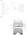
Figure 2 is a truck having a system offigure 1 , and -
Figure 3 is a diagram corresponding to a method for controlling a proposal of functions on a display of a remote control device. - In order to make the figures easier to read, the various elements are not necessarily represented to scale. In these figures, identical elements receive the same reference number. Certain elements or parameters can be indexed, i.e. designated for example by first element or second element, or first parameter and second parameter, etc.
-
Figure 1 shows on the left sensors, in the centre anelectronic control unit 2 and a controlledequipment 4, and on the right aremote control 6. In this disclosure, this system is built in a vehicle like a truck, for example a light, medium or heavy duty vehicle. - The
remote control device 6 is an electronic device with a casing equipped with input means 60 and output means with adisplay 62. Thisremote control device 6 may look like a mobile phone, or a tablet computer. In this case, thedisplay 62 may be a touchscreen so that the input means 60 are built-in thedisplay 62. - The
remote control device 6 may also be a controller with adisplay 62 and input means 60 formed by hardware buttons placed along one or more edges of saiddisplay 62. - The
remote control device 6 may also have output means like LEDs. One (or more) LED may be associated to a hardware button. The output means may be visual means (display, light(s), ...) but they may also be audio means like speaker(s) or tactile means like a vibration generator, e.g. haptic feedback. - The
remote control device 6 is a wireless device. To communicate with theelectronic control unit 2, it comprises wireless reception/transmission means 64. Theelectronic control unit 2 comprises on its side corresponding wireless transmission/reception means 20. The reception/transmission means 64 communicate with the transmission/reception means 20 over a network. For example, the network may include a short-range network (e.g. Bluetooth, ultra-wideband, Wi-Fi, NFC, ...). - The vehicle, namely a truck 50 (
figure 2 ) comprising this system for remote control displays and controls of truck functions may comprise several electronic control units. For example, the comfort devices (windows opening and/or light and/or radio, ...) may be controlled by an electronic control unit and another (one or more) electronic control device may control functions concerning directly the vehicle (e.g. suspension) or bodybuilder functions. As a non exhaustive example, a first set of truck functions may concern the command of the comfort devices, a second set of truck functions may concern the command of the function concerning the vehicle and a third set of functions may concern the bodybuilder functions. Preferably, a single electronic control unit (electronic control unit 2) is equipped with wireless transmission/reception means 20 able to communication with theremote control device 6. The electronic control units may communicate with each other by multiplexing. Said otherwise theelectronic control unit 2 acts as a gateway for controlling various pieces of equipment. -
Figure 1 shows a controlledequipment 4 in connection with theelectronic control unit 2. In accordance with the preceding paragraph, theelectronic control unit 2 may be directly connected to the controlled equipment or through a wired network and possibly through another control unit. The corresponding control unit comprises the actuation means for the controlledequipment 4. This equipment can be monitored by an input on theremote control device 6. The command is transmitted by theremote control device 6 to theelectronic control unit 2 which can directly, or through multiplexing for example, send an actuation command to the controlled equipment. - Although
figure 1 only shows a controlledequipment 4, theremote control device 6 and the disclosed system are designed to control a large number of pieces of equipment like controlled equipment 4 (for example window offigure 2 ). The system is designed for controlling all the functions that are usually controlled with a remote control (and eventually also more functions) with only one remote control, i.e. theremote control device 6. To this end, it is proposed the input means 60 and the output means with thedisplay 62 are contextualized depending on the position of thedriver 80 and/or of theremote control device 6. In this way for example, if thedriver 80 is outside of the vehicle with theremote control device 6, thedisplay 62 will present information and/or will propose functions which are different of the information and/or functions presented or proposed when thedriver 80 is in the vehicle with theremote control device 6. In other words, thedisplay 62 of theremote control device 6 is configured to display at least two different user interfaces depending of the position of thedriver 80 and/or of theremote control device 6. The input means are also contextualised according to driver location, orremote control device 6 location, in-out of the vehicle (or of a cab of the vehicle). - The
electronic control unit 2 is designed for determining the position of thedriver 80 and/or of theremote control device 6 according to information received from the sensors. -
Figure 1 shows five sensors. The system can work with less sensors and also with more sensors. The following description gives examples of sensors that can be used for determining the position of thedriver 80 and/or of the remote control device 6 (location in-out of the vehicle). This is not an exhaustive list of sensors which can be used in relation to the described system. With the help of following sensors (or other ones), the system can determine thedriver 80 and/orremote control device 6 location. The system interprets then the driver intention and proposes him a specific group of functions (for example radio on/off, light on/off, ... if thedriver 80 lies in a bunk area of the vehicle). The inputs of theremote control device 6 are also contextualized in accordance with the user interface shown by the display and the position of thedriver 80 and/orremote control device 6. -
Reference 100 onfigure 1 may refer to a bunk mattress sensor that is able to determine the presence of a person (the driver 80) on the bunk mattress. Bunk mattress sensor can be a weight sensor in the bedding or can be a infrared presence detector. - Reference 200 on
figure 1 may refer to a camera or more generally to a video surveillance system which is able to determine the presence of a person in a predetermined area. A camera may be positioned in a cab of the vehicle for detecting a person inside the cab. A camera may be placed in addition or instead of the camera in the cab for detecting a person outside the vehicle, for example at the back of the vehicle. -
Reference 300 onfigure 1 may refer to a seat sensor. Such a sensor is usually used to detect the presence of a person on a seat. It can be used in combination with a sensor detecting if the corresponding seat belt is fastened and an alarm may be triggered if a person sits on the seat and the seat belt is not fastened. This seat sensor may also be connected toelectronic control unit 2 and may inform the system if thedriver 80 sits on his seat. -
Reference 400 onfigure 1 refers to a radar sensor. Such a sensor can detect a movement of a person. Other similar sensor may be used, for example a lidar sensor or an ultra sonic sensor. A radar sensor or a similar sensor accurately placed in the cab of the vehicle is able to detect if thedriver 80 is in the cab or may detect when thedriver 80 goes in or out of the cab. -
Reference 500 onfigure 1 refers to a Bluetooth beacon. This kind of sensor is preferably a Bluetooth low energy (or BLE) beacon. This kind of sensor accurately placed in the cab can determine if theremote control device 6 is located in the cab or not. - As an alternative to a Bluetooth beacon, a set of three sensors using ultra wide band technology can be used to determine the location of the
remote control device 6. Each sensor can determine the distance between it and theremote control device 6. Since the location of each of these three sensors is known, it is possible to determine the location of theremote control device 6. This ultra wide band (UWB) system can precisely locate theremote control device 6 in or out of the cab of the vehicle. - According to one embodiment there may be provided various antennas arranged at the vehicle cabin and configured to cooperate with the
remote control device 6 in order to determine which antenna receives the most powerful signal from the remote control device in response to radio waves impinged from the antennas. Such antennas can be arranged in the driver door, in the external rear view mirror, in the internal rear view mirror, in the dashboard, etc. - The system for remote control displays and controls of truck functions may for example comprise sensors, e.g. a camera(s), which allow to determine if the
driver 80 is in the cab of the vehicle and/or other sensors, e.g. three UWB sensors, which allow to determine the position of theremote control device 6. - The system for remote control displays and controls of truck functions shown on
figure 1 may work in the following way (figure 3 ): - The sensors (100 and/or 200 and/or 300 and/or 400 and/or 500 and/or other sensors) are working to detect (step A), and eventually to locate, a
driver 80 of the corresponding vehicle, for example a truck, and/or to detect, and eventually to locate, theremote control device 6. - The information given by one (or more) sensor(s) is transmitted (step B) to the
electronic control unit 2 which monitors thedriver 80 and/orremote control device 6 location. For example, theelectronic control unit 2 may monitor the location of thedriver 80 and may take in account three different position of the driver. The location of the driver is in or out of the cab of the truck (or other industrial vehicle). If thedriver 80 is in the cab of the truck, he can be in the bunk area or not. The same can be done for the remote control device 6: it can be out of the cab, in the cab and in this case it is or not in the bunk area. Nine different cases can be envisaged. For each of these cases, a predetermined master for the user interface of theremote control device 6, i.e. a master for the inputs and outputs of theremote control device 6, is foreseen. Theelectronic control unit 2 determines the adapted master of user interface among the predetermined masters (step C) according to the location of thedriver 80 and/or of theremote control device 6. A same master, or user interface, can correspond to two or more cases among the nine cases. The contextualised master is stored in a memory of theremote control device 6 and theelectronic control unit 2 informs theremote control device 6 about the user interface (for example chosen between three different user interfaces) which has to be used. Theremote control device 6 adapts the user interface (output means including the display and input means) in accordance with the information received from the electronic control unit 2 (step D). - Each user interface proposes different truck functions to the
driver 80. For example, if thedriver 80 is located in the bunk area, thedisplay 62 will give information about entertainment devices (TV, radio, ...) and comfort devices (light, temperature, ...) and the input means will correspond to actions on these devices: more or less loud, light on/off, action on the climate control, .... If thedriver 80 is out of the cab of the vehicle, the user interface on the remote control device will propose for example a set of functions concerning the bodybuilder and the suspension of the vehicle. - The
remote control device 6 may also include a gravity sensor and the user interface on thedisplay 62 can be adapted according to the spatial orientation of theremote control device 6 detected by the gravity sensor. - If the
driver 80 acts on the input means, the corresponding command is transmitted through the reception/transmission means 64 of theremote control device 6 to theelectronic control unit 2. At theelectronic control unit 2 the transmission/reception means 20 receives signals (e.g. electromagnetic waves). Theelectronic control unit 2 also comprises actuation means adapted to send an appropriate command to the controlledequipment 4 which corresponds to the choice of thedriver 80. - The proposed system can limit the number of remote controls onboard of a vehicle like a truck or another industrial vehicle. A single remote control device allows the driver to access all the truck functions. The user interface of the remote control device is automatically adapted to the need of the driver. The contextualised displays and controls improve the user experience for the driver.
- Furthermore, the proposed system can be easily implemented on a vehicle. It can be adapted to a large number of kinds of vehicles. The cost of implementation is limited because the hardware is reduced in comparison to prior art solutions.
- It is not excluded to consider using the above
remote control device 6 also for keyless entry and for keyless start of the engine. In the state, theremote control device 6 also replaces a conventional key for door and ignition.
Claims (15)
- System for remote control displays and controls of truck functions, characterised in that it comprises:- a remote control device (6) with:- - a display (62) with display control means for at least two user interfaces, each user interface corresponding to a predetermined set of truck functions,- - wireless transmission and reception means (64), and- - input means (60) for selecting a function proposed on the display (62)- actuation means (2) corresponding to the proposed truck functions,- at least a sensor (100, 200, 300, 400, 500) for detecting a position of a person and/or of the remote control device (6),
wherein the display control means are configured to propose functions on the display (62) depending on the information received from the at least one sensor (100, 200, 300, 400, 500) for detecting a position. - System according to claim 1, wherein the remote control device (6) is remotely connected to a single connecting point (2, 20) including the reception means and in relation with a control unit.
- System according to one of the preceding claims, wherein there are at least three sensors using Ultra Wide Band (UWB) technology for detecting the position of the remote control device (6).
- System according to one of the preceding claims, wherein the system also comprises a seat sensor (300).
- System according to one of the preceding claims, wherein the system also comprises a bunk mattress sensor (100).
- System according to one of the preceding claims, wherein the system also comprises a camera (200) for controlling a position of a person in-out of a cab of the truck.
- System according to one of the preceding claims, wherein the system also comprises ultra sonic sensors (400).
- System according to one of the preceding claims, wherein the remote control device (6) comprises a touchscreen and/or hardware buttons (60).
- System according to one of the preceding claims, wherein the remote control device (6) comprises a display (62) and/or at least a LED and/or a sound feedback and/or a vibration feedback.
- Method for controlling a proposal of functions on a display (62) of a remote control device (6), characterised in that it comprises:- detection (A) by at least one sensor (100, 200, 300, 400, 500) of the location of a person and/or of the remote control device (6) inside or outside an industrial vehicle,- transmission (B) of the detected position of the person and/or the remote control device (6) to a control unit (2),- determination of an user interface (C) among predetermined user interfaces according to the detected position of the person and/or the remote control device (6) and wherein each user interface proposes a set of truck functions that can be controlled by the remote control device (6)- displaying the determined user interface (D) on the display (62).
- Method according to claim 10, wherein if a person is detected inside the industrial vehicle, a further step determines if the person is sitting on a seat or lying on a bunk mattress.
- Method according to claim 10 or 11, wherein the spatial orientation of the remote control device (6) is detected.
- Method according to any of claims 10 to 12, wherein it comprises the detection of the position of a person and the detection of the position of the remote control device (6).
- Method according to any of claims 10 to 13, wherein at least three user interfaces are proposed:- at least one user interface is proposed if the person and/or the remote control device is detected outside the industrial vehicle;- at least one user interface is proposed if the person and/or the remote control device is detected sitting on a seat inside a cab of the industrial vehicle;- at least one user interface is proposed if the person and/or the remote control device is detected in a bunk area of the cab of the industrial vehicle.
- A truck comprising a system for remote control displays and controls of truck functions to one of claims 1-9.
Priority Applications (2)
| Application Number | Priority Date | Filing Date | Title |
|---|---|---|---|
| EP22169916.8A EP4269155A1 (en) | 2022-04-26 | 2022-04-26 | System for remote controls and displays for an industrial vehicle |
| US18/303,655 US20230342014A1 (en) | 2022-04-26 | 2023-04-20 | System for remote controls and displays for an industrial vehicle |
Applications Claiming Priority (1)
| Application Number | Priority Date | Filing Date | Title |
|---|---|---|---|
| EP22169916.8A EP4269155A1 (en) | 2022-04-26 | 2022-04-26 | System for remote controls and displays for an industrial vehicle |
Publications (1)
| Publication Number | Publication Date |
|---|---|
| EP4269155A1 true EP4269155A1 (en) | 2023-11-01 |
Family
ID=81387138
Family Applications (1)
| Application Number | Title | Priority Date | Filing Date |
|---|---|---|---|
| EP22169916.8A Pending EP4269155A1 (en) | 2022-04-26 | 2022-04-26 | System for remote controls and displays for an industrial vehicle |
Country Status (2)
| Country | Link |
|---|---|
| US (1) | US20230342014A1 (en) |
| EP (1) | EP4269155A1 (en) |
Citations (5)
| Publication number | Priority date | Publication date | Assignee | Title |
|---|---|---|---|---|
| FR2875049A1 (en) | 2004-09-08 | 2006-03-10 | Renault V I Sa | Information system for e.g. tractor, has software unit implemented on computer to simultaneously display information relative to vehicle and/or its environment, based on selection carried out by vehicle`s driver and/or vehicle`s state |
| DE102006060514A1 (en) * | 2006-12-21 | 2008-06-26 | Daimler Ag | Operating and display system for a level control device of a coach or commercial vehicle comprises multifunctional operating units with optical display units and manual operating units |
| DE102016012283A1 (en) * | 2016-10-14 | 2017-04-27 | Daimler Ag | Central control device |
| US20200016998A1 (en) * | 2018-07-13 | 2020-01-16 | Grammer Ag | Vehicle seat with operating device |
| DE102020105042A1 (en) | 2020-02-26 | 2021-08-26 | Audi Aktiengesellschaft | Method for setting an operating device |
-
2022
- 2022-04-26 EP EP22169916.8A patent/EP4269155A1/en active Pending
-
2023
- 2023-04-20 US US18/303,655 patent/US20230342014A1/en active Pending
Patent Citations (5)
| Publication number | Priority date | Publication date | Assignee | Title |
|---|---|---|---|---|
| FR2875049A1 (en) | 2004-09-08 | 2006-03-10 | Renault V I Sa | Information system for e.g. tractor, has software unit implemented on computer to simultaneously display information relative to vehicle and/or its environment, based on selection carried out by vehicle`s driver and/or vehicle`s state |
| DE102006060514A1 (en) * | 2006-12-21 | 2008-06-26 | Daimler Ag | Operating and display system for a level control device of a coach or commercial vehicle comprises multifunctional operating units with optical display units and manual operating units |
| DE102016012283A1 (en) * | 2016-10-14 | 2017-04-27 | Daimler Ag | Central control device |
| US20200016998A1 (en) * | 2018-07-13 | 2020-01-16 | Grammer Ag | Vehicle seat with operating device |
| DE102020105042A1 (en) | 2020-02-26 | 2021-08-26 | Audi Aktiengesellschaft | Method for setting an operating device |
Also Published As
| Publication number | Publication date |
|---|---|
| US20230342014A1 (en) | 2023-10-26 |
Similar Documents
| Publication | Publication Date | Title |
|---|---|---|
| EP1836075B1 (en) | Remote control method and system, vehicle with remote controllable function, and control server | |
| KR101813532B1 (en) | Communication Module, vehicle and method for controlling the same | |
| EP3243194B1 (en) | Trainable transceiver with single camera park assist | |
| EP1369837B1 (en) | Surveillance system, method of remotely controlling sensor apparatus, and surveillance remote controller | |
| US10717432B2 (en) | Park-assist based on vehicle door open positions | |
| JP2008509611A (en) | Two-way radio monitoring system | |
| US10960849B2 (en) | Remote control button actuator with removable tray | |
| CN103481821B (en) | For confirming to give the system and method for the potential unexpected order of vehicle | |
| EP2965294B1 (en) | Communication system for a vehicle and method for training the communication system | |
| KR102491371B1 (en) | Remote control device and vehicle including the same | |
| US9956911B2 (en) | Object detection for vehicles | |
| CN113543027B (en) | Mobile terminal forgetting prevention method, vehicle and computer readable storage medium | |
| WO2015115064A1 (en) | Vehicle control system, portable terminal, and vehicle-side device | |
| EP4269155A1 (en) | System for remote controls and displays for an industrial vehicle | |
| JP2005344335A (en) | Door lock control system, door lock control device, and door lock control method | |
| US11754988B2 (en) | Information processing device, information processing method and recording medium | |
| KR101407561B1 (en) | System and method for detecting invasion of vehicle | |
| JP2012046099A (en) | Wireless interface device and electronic key | |
| US20220355813A1 (en) | Vehicle having user inputs controlled based on monitored pet location | |
| KR100544332B1 (en) | Antenna module for remote engine starting of vehicle and method for displaying vehicle information using the antenna module | |
| CN115311875A (en) | Remote autonomous driving control management apparatus, system including the same, and method thereof | |
| KR102489959B1 (en) | Vehicle and control method thereof | |
| US11981205B2 (en) | In-vehicle phone finder | |
| JPWO2019021534A1 (en) | Portable information terminal protection case and information communication system | |
| KR101471747B1 (en) | Antitheft system using movable senser for vehicle and method thereof |
Legal Events
| Date | Code | Title | Description |
|---|---|---|---|
| PUAI | Public reference made under article 153(3) epc to a published international application that has entered the european phase |
Free format text: ORIGINAL CODE: 0009012 |
|
| STAA | Information on the status of an ep patent application or granted ep patent |
Free format text: STATUS: THE APPLICATION HAS BEEN PUBLISHED |
|
| AK | Designated contracting states |
Kind code of ref document: A1 Designated state(s): AL AT BE BG CH CY CZ DE DK EE ES FI FR GB GR HR HU IE IS IT LI LT LU LV MC MK MT NL NO PL PT RO RS SE SI SK SM TR |
|
| STAA | Information on the status of an ep patent application or granted ep patent |
Free format text: STATUS: REQUEST FOR EXAMINATION WAS MADE |
|
| 17P | Request for examination filed |
Effective date: 20240118 |
|
| RBV | Designated contracting states (corrected) |
Designated state(s): AL AT BE BG CH CY CZ DE DK EE ES FI FR GB GR HR HU IE IS IT LI LT LU LV MC MK MT NL NO PL PT RO RS SE SI SK SM TR |