EP4269116A1 - Printer with a sensor to detect a remaining amount of the roll sheet - Google Patents
Printer with a sensor to detect a remaining amount of the roll sheet Download PDFInfo
- Publication number
- EP4269116A1 EP4269116A1 EP23157014.4A EP23157014A EP4269116A1 EP 4269116 A1 EP4269116 A1 EP 4269116A1 EP 23157014 A EP23157014 A EP 23157014A EP 4269116 A1 EP4269116 A1 EP 4269116A1
- Authority
- EP
- European Patent Office
- Prior art keywords
- sheet
- flapper
- printer according
- rolled sheet
- printer
- Prior art date
- Legal status (The legal status is an assumption and is not a legal conclusion. Google has not performed a legal analysis and makes no representation as to the accuracy of the status listed.)
- Granted
Links
Images




Classifications
-
- B—PERFORMING OPERATIONS; TRANSPORTING
- B41—PRINTING; LINING MACHINES; TYPEWRITERS; STAMPS
- B41J—TYPEWRITERS; SELECTIVE PRINTING MECHANISMS, i.e. MECHANISMS PRINTING OTHERWISE THAN FROM A FORME; CORRECTION OF TYPOGRAPHICAL ERRORS
- B41J15/00—Devices or arrangements of selective printing mechanisms, e.g. ink-jet printers or thermal printers, specially adapted for supporting or handling copy material in continuous form, e.g. webs
- B41J15/04—Supporting, feeding, or guiding devices; Mountings for web rolls or spindles
-
- B—PERFORMING OPERATIONS; TRANSPORTING
- B41—PRINTING; LINING MACHINES; TYPEWRITERS; STAMPS
- B41J—TYPEWRITERS; SELECTIVE PRINTING MECHANISMS, i.e. MECHANISMS PRINTING OTHERWISE THAN FROM A FORME; CORRECTION OF TYPOGRAPHICAL ERRORS
- B41J11/00—Devices or arrangements of selective printing mechanisms, e.g. ink-jet printers or thermal printers, for supporting or handling copy material in sheet or web form
- B41J11/0075—Low-paper indication, i.e. indicating the state when copy material has been used up nearly or completely
-
- B—PERFORMING OPERATIONS; TRANSPORTING
- B41—PRINTING; LINING MACHINES; TYPEWRITERS; STAMPS
- B41J—TYPEWRITERS; SELECTIVE PRINTING MECHANISMS, i.e. MECHANISMS PRINTING OTHERWISE THAN FROM A FORME; CORRECTION OF TYPOGRAPHICAL ERRORS
- B41J15/00—Devices or arrangements of selective printing mechanisms, e.g. ink-jet printers or thermal printers, specially adapted for supporting or handling copy material in continuous form, e.g. webs
- B41J15/04—Supporting, feeding, or guiding devices; Mountings for web rolls or spindles
- B41J15/042—Supporting, feeding, or guiding devices; Mountings for web rolls or spindles for loading rolled-up continuous copy material into printers, e.g. for replacing a used-up paper roll; Point-of-sale printers with openable casings allowing access to the rolled-up continuous copy material
Definitions
- Embodiments described herein relate generally to a printer.
- a printer that can print an image on a rolled sheet is used in a store or the like.
- the rolled sheet is formed by winding a print sheet in a roll shape.
- the printer prints an image after pulling out a part of the print sheet from the rolled sheet.
- a so-called drop-in method has been proposed in which the rolled sheet can be loaded only by inserting the rolled sheet into a storage unit of the printer.
- the direction in which the rolled sheet is pressed and the direction in which the print sheet is pulled out are opposite to each other.
- the printer main body is placed vertically, if the remaining amount of the rolled sheet decreases, the rolled sheet may slip down in the gravitational direction. Further, when the rolled sheet slips down, there is a case where it is not possible to detect that the rolled sheet is close to the paper shortage.
- Embodiments provide a drop-in printer capable of accommodating a print sheet in a storage unit even in a state where the remaining amount of the print sheet is small.
- a printer includes a housing in which a sheet is stored in a rolled shape, a head by which an image is printed on the sheet, a flapper configured to pivot around an axis at a first end thereof including a surface extending from the first end to a second end of the flapper and biased to press the stored sheet against the housing, and a protrusion at the first end of the flapper that rotates around the axis as the flapper pivots, a sensor, and a controller configured to issue a signal when the protrusion is rotated around the axis to move into a detection range of the sensor.
- One of the objects of the present invention is to improve prior art techniques and overcome at least some of the prior art problems as for instance above illustrated.
- a printer comprising a housing in which a sheet is stored in a rolled shape; a head by which an image is printed on the sheet; a flapper configured to pivot around an axis at a first end thereof including a surface extending from the first end to a second end of the flapper and biased to press the stored sheet against the housing, and a protrusion at the first end of the flapper that rotates around the axis as the flapper pivots; a sensor and a controller configured to issue a signal when the protrusion is rotated around the axis to move into a detection range of the sensor.
- the printer according to the first aspect of the invention further comprises a cover for an opening of the housing through which the sheet is set, wherein the surface of the flapper presses the stored sheet in a direction away from the cover.
- the senor is a photosensor including a light emitter that emits light and a light receiver that faces the light emitter and receives the light, and the detection range is between the light emitter and the light receiver.
- housing includes a recess that the stored sheet having a diameter smaller than a predetermined diameter can enter.
- protrusion is rotated to move into the detection range when the stored sheet has entered the recess.
- the housing includes an inclined surface that is inclined with respect to the cover.
- the head is located at one end of the inclined surface, and the recess is located at the other end of the inclined surface that is farther from the cover than said one end of the inclined surface.
- a step portion is formed between the other end of the inclined surface and the recess so as to contact the stored sheet having a diameter equal to or greater than the predetermined diameter.
- the flapper includes a torsion spring that generates a bias force for the surface of the flapper.
- the sheet is a thermal sheet
- the head includes a plurality of heating elements to form the image on the thermal sheet.
- a printer comprising a housing in which a sheet is stored in a rolled shape; a head by which an image is printed on the sheet; a flapper configured to pivot around an axis at a first end thereof and biased to press the stored sheet against the housing; a protrusion that rotates around the axis as the flapper pivots; a sensor; and a controller configured to issue a signal when the protrusion is rotated around the axis to move into a detection range of the sensor.
- the printer according to the second aspect of the invention further comprises a cover for an opening of the housing through which the sheet is set, wherein the flapper presses the stored sheet in a direction away from the cover.
- the senor is a photosensor including a light emitter that emits light and a light receiver that faces the light emitter and receives the light, and the detection range is between the light emitter and the light receiver.
- the housing includes a recess that the stored sheet having a diameter smaller than a predetermined diameter can enter.
- the protrusion is rotated to move into the detection range when the stored sheet has entered the recess.
- the housing includes an inclined surface that is inclined with respect to the cover.
- the head is located at one end of the inclined surface, and the recess is located at the other end of the inclined surface that is farther from the cover than said one end of the inclined surface.
- a step portion is formed between the other end of the inclined surface and the recess so as to contact the stored sheet having a diameter equal to or greater than the predetermined diameter.
- the flapper includes a torsion spring that generates a bias force for the surface of the flapper.
- the sheet is a thermal sheet
- the head includes a plurality of heating elements to form the image on the thermal sheet.
- thermal printer 10 according to an embodiment of the present invention will be described in detail with reference to the accompanying drawings.
- FIG. 1 is a perspective view illustrating an example of an external appearance of the thermal printer 1.
- the X-axis, the Y-axis, and the Z-axis orthogonal to each other are shown, and the left-right direction (X-direction), the front-rear direction (Y-direction), and the up-down direction (Z-direction) in the thermal printer 1 be described using the X-axis, the Y-axis, and the Z-axis.
- the X direction, the Y direction, or the Z direction it is the respective axial directions, and includes two directions in opposite directions.
- the direction is one direction from the right side to the left side
- the direction is one direction from the rear side to the front side
- the direction is one direction from the lower side to the upper side.
- the thermal printer 1 includes a lower housing 11, an upper cover 12, and a discharge port 13.
- the lower housing 11 is a box-shaped container in which an opening is provided along its upper surface.
- the lower housing 11 is provided with a connection terminal (not shown) used for connection with an external device such as a host computer for managing the thermal printer 1, a power supply terminal (not shown) for supplying power to the printer 1, and the like.
- the upper cover 12 covers a storage unit 18 disposed in the lower housing 11 (see FIG. 2 ).
- the upper cover 12 is rotatably supported along one end of the lower housing 11, and covers the opening of the lower housing 11 in accordance with the rotation.
- the discharge port 13 is a gap-shaped opening through which a sheet is discharged, and the opening is formed between the other end of the upper cover 12 and the lower housing 11.
- the lower housing 11 and the upper cover 12 constitute the housing 10.
- FIG. 3 is a YZ cross-sectional view of the thermal printer 1 according to an embodiment.
- the thermal printer 1 stores a thermal paper 21 as a rolled sheet 22 wound around a roll core 23 in a roll shape in the storage unit 18 of the housing 10, and performs printing while drawing the thermal paper 21 out of the rolled sheet 22.
- the rolled sheet 22 in FIG. 2 shows a state in which the remaining amount of the rolled sheet 22 is sufficient.
- the rolled sheet 22 in FIG. 3 shows a state in which the remaining amount of the rolled sheet 22 is small (i.e., has reached a predetermined amount).
- the print sheet is not limited to the thermal paper 21, and may be, for example, a label sheet.
- the label sheet may include a plurality of strip-shaped labels each having a predetermined size and attached to a strip-shaped base sheet, or may include a plurality of strip-shaped labels without any base sheet.
- the thermal printer 1 includes a flapper 15, a platen roller 16, a thermal head 17, and the storage unit 18 inside the housing 10.
- the thermal printer 1 draws the thermal paper 21 from the rolled sheet 22 by the rotation of the platen roller 16, and performs printing on the drawn thermal paper 21 by the thermal head 17.
- the flapper 15 is also referred to as a pressing member.
- the flapper 15 is provided on the rear side of the upper cover 12.
- the flapper 15 is rotatably attached to the upper cover 12 an end portion of the side close to the thermal head 17, and with its rotation, the rolled sheet 22 accommodated in the storage unit 18 is pressed in a direction away from the upper cover 12 side against an inner wall 19 of the storage unit 18.
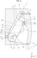
- FIG. 4 is a side view illustrating an example of the shape of the flapper 15.
- FIG. 5 is a perspective view illustrating the example of the shape of the flapper 15.
- a flapper base portion 25 at the base of the flapper 15 includes a flapper rotation shaft 42.
- the flapper rotation shaft 42 is rotatably supported along the rear surface of the upper cover 12. Further, a sheet holding unit 26 is formed at the leading end of the flapper 15.
- the sheet holding unit 26 is a member extending from the flapper base portion 25 at the root of the flapper 15 to the Y-axis direction negative side. The sheet holding unit 26 is brought into contact with the rolled sheet 22 to press the outer peripheral surface of the rolled sheet 22 against the storage unit 18 described later.
- the flapper 15 is mounted along the rear surface side of the upper cover 12 so as to be rotatable around the flapper rotation shaft 42 in a state of being biased in the direction of the rolled sheet 22 accommodated in the storage unit 18.
- the flapper base portion 25 includes a protruding portion 27 which is a thin piece protruding in the radial direction around the flapper rotation shaft 42.
- the protruding portion 27 is a member that is provided at an end portion of the flapper base portion 25 that is rotatably attached to the upper cover 12 and protrudes in the radial direction of the rotation.
- the protruding portion 27 is a member for causing a photosensor 30 to detect that the remaining amount of the rolled sheet 22 has reached a predetermined amount.
- the protruding portion 27 protrudes toward the positive side in the Y-axis direction with respect to the flapper base portion 25.
- the protruding portion 27 faces the sheet holding unit 26. The detection of the protruding portion 27 by the photosensor 30 will be described later.
- the shape of the sheet holding unit 26 is not limited to the example of FIG. 5 .
- the sheet holding unit 26 may include a plurality of members for holding the sheet.
- the flapper rotation shaft 42 is installed along the X-axis at a position on the positive side in the Y-axis direction with respect to the upper cover rotation shaft 14 by which the upper cover 12 is rotated.
- a torsion spring (not shown) is attached to the flapper rotation shaft 42, and the flapper 15 is biased by the torsion spring in the direction of the rolled sheet 22 accommodated in the storage unit 18.
- the platen roller 16 is installed along the rear surface side of the upper cover 12.
- the platen roller 16 operates as a conveying unit.
- the platen roller 16 is rotated by a driving force transmitted from a stepping motor (not shown) to pull out the thermal paper 21 from the rolled sheet 22 stored in the storage unit 18 and convey it from the storage unit 18, which is an upstream side, toward the thermal head 17, which is a downstream side.
- the thermal head 17 is installed along the inner surface of the lower housing 11.
- the thermal head 17 operates as a printing unit.
- the thermal head 17 is in close contact with the platen roller 16 in a state where the upper cover 12 is closed.
- the thermal head 17 performs printing on the thermal paper 21 conveyed by the platen roller 16.
- the thermal paper 21 is conveyed toward the discharge port 13 in a state of being sandwiched between the thermal head 17 and the platen roller 16.
- the thermal head 17 has a structure in which a plurality of heating elements are aligned, and performs printing on the thermal paper 21 sandwiched between the thermal head 17 and the platen roller 16 by causing the heating elements corresponding to a printing pattern to generate heat.
- the storage unit 18 stores the rolled sheet 22, which is the thermal paper 21 wound around the roll core 23 in a roll shape.
- the storage unit 18 includes the inner wall 19 and a recessed portion 20.
- the rolled sheet 22 is accommodated in the storage unit 18 in a state of being in contact with the inner wall 19.
- the inner wall 19 has a wall surface extending to the positive side in the Z-axis direction, and has an inclined surface rising toward the discharge port 13 along the positive side in the Y-axis direction.
- the inner wall 19 includes the recessed portion 20.
- the recessed portion 20 is provided at a position where the rolled sheet 22 that has reached a predetermined amount is pressed against the inner wall 19 of the storage unit 18 by the flapper 15.
- the recessed portion 20 is located in the vicinity of a corner formed by the bottom surface of the housing 10 in the vertical position and the bottom surface in the horizontal position. When the rolled sheet 22 pressed by the flapper 15 reaches the predetermined amount, it is pressed against the recessed portion 20.
- the recessed portion 20 further includes a convex portion 201 (or a step portion).
- the convex portion 201 is provided at an edge of the recessed portion 20 on the side close to the thermal head 17 so as to form a step on the inner wall 19.
- the rolled sheet 22 accommodated in the storage unit 18 is supported at three points: a contact point with the flapper 15, a contact point with the recessed portion 20, and a contact point with the inclined surface of the recessed portion 20.
- the thermal paper 21 is pulled out from the rolled sheet 22 at the contact point with the vertical direction of the recessed portion 20.
- the contact point between the rolled sheet 22 and the vertical side of the recessed portion 20 is referred to as an extraction point 24.
- the flapper 15 is rotatably attached to the upper cover 12 by the flapper rotation shaft 42.
- the rolled sheet 22 is pressed against the recessed portion 20 or the inner wall 19 by being pressed by the flapper 15 which rotates clockwise in FIGS. 2 and 3 .
- the force applied to the contact point 151 between the flapper 15 and the rolled sheet 22 is F
- the force applied to the extraction point 24 of the recessed portion 20 with the rolled sheet 22 is divided into a component force Fa toward the positive side of the Y-axis and a component force Fb toward the negative side of the Z-axis. That is, the rolled sheet 22 is pressed against the inner wall 19 so as to have a pressing force toward the direction (i.e., Y-axis positive side) in which the thermal paper 21 is pulled out.
- the flapper 15 has a surface that is substantially parallel to the inner wall 19 in a state in which the rolled sheet 22 that has reached the predetermined amount is pressed.
- the rolled sheet 22 is pressed toward the direction in which the thermal paper 21 is drawn out at the extraction point 24, regardless of the state in which printing is performed on the thermal paper 21 and the state in which printing is not performed.
- the flapper 15 suppresses the movement of the rolled sheet 22 inside the recessed portion 20.
- the rolled sheet 22 comes into contact with the convex portion 201 (not shown), the rolled sheet 22 comes into contact with the convex portion 201.
- the convex portion 201 and the rolled sheet 22 come into contact with each other, movement of the rolled sheet 22 inside the recessed portion 20 is suppressed.
- the thermal paper 21 drawn out from the extraction point 24 is conveyed in the direction of the arrow B as the platen roller 16 rotates.
- a front surface 211 of the thermal paper 21 is a printing surface. Printing is performed on the front surface 211 of the thermal paper 21 by the thermal head 17. The printed thermal paper 21 is discharged from the discharge port 13.
- the discharge port 13 is provided with a cutter (not shown). The user of the thermal printer 1 cuts the thermal paper 21 that has been discharged after the printing is completed by the cutter.
- the rolled sheet 221 shown in FIG. 3 indicates the position of the rolled sheet 221 inside the storage unit 18 when the rolled sheet 221 is a label paper wound without a base sheet.
- the front surface of the label paper is a printing surface
- the back surface is an adhesive layer.
- the photosensor 30 is installed on the inner surface of the upper cover 12.
- the photosensor 30 detects that the remaining amount of the rolled sheet 22 has reached a predetermined amount, that is, that the thermal paper 21 has run out of paper (i.e., near-end).
- the photosensor 30 detects a portion of the flapper 15 that presses the rolled sheet 22 whose remaining amount has reached a predetermined amount, which is displaced by rotation.
- the photosensor 30 is provided at any position where the protruding portion 27 can be detected when the flapper 15 presses the rolled sheet 22 that has reached the predetermined amount. That is, when the remaining amount of the rolled sheet 22 has reached the predetermined amount, the photosensor 30 overlaps with the protruding portion 27 when viewed from the positive side in the Z-axis direction.
- the photosensor 30 is, for example, a transmissive photosensor in which a light emitter that emits light and a light receiver that receives light are integrated.
- the photosensor 30 is formed in a substantially U-shape, and when viewed from the positive side in the Z-axis direction, the opening of the U-shape is arranged toward the negative side in the Y-axis direction (see FIGS. 7 and 8 ).
- the light emitter is an LED (Light Emitting Diode)
- the light receiver is a photodiode or a phototransistor.
- the light receiver outputs different signals depending on whether the light emitted by the light emitter has been reflected and received.
- FIG. 6 is an enlarged view of the region C shown in FIG. 3 .
- the positional relationship between the flapper 15 and the photosensor 30 shown in FIG. 6 indicates a state in which the remaining amount of the rolled sheet 22 has reached the predetermined amount.
- the protruding portion 27 of the flapper 15 is within a detection area of the photosensor 30.
- the protruding portion 27 is within an angular range detectable by the photosensor 30 when the flapper 15 presses the rolled sheet 22 having the predetermined amount or less.
- the photosensor 30 detects that the remaining amount of the rolled sheet 22 has reached the predetermined amount by detecting the protruding portion 27. Then, the thermal printer 1 issues a signal that notifies that the remaining amount of the rolled sheet 22 has reached the predetermined amount to turn on or blink an indicator such as a lamp or an LED disposed on an outer surface of the lower housing 11 or the upper cover 12, for example. Additionally or alternatively, the thermal printer 1 can issue a signal that notifies a host computer (not shown) connected thereto via a network interface circuit that the remaining amount of the rolled sheet 22 has reached the predetermined amount. Such signals may be issued and output by a controller, a control circuit, or a processor of the thermal printer 1 (not shown) for controlling various components of the thermal printer 1 including the platen roller 16 and the thermal heat 17.
- FIG. 7 and FIG. 8 are diagrams for explaining a method by which the photosensor 30 detects the remaining amount of the rolled sheet 22.
- FIG. 7 shows the positions of the flapper 15 and the photosensor 30 when the remaining amount of the rolled sheet 22 has not reached the predetermined amount, that is, the remaining amount of the rolled sheet 22 is sufficiently present.
- FIG. 8 shows the positions of the flapper 15 and the photosensor 30 when the remaining amount of the rolled sheet 22 has reached the predetermined amount, that is, the remaining amount of the rolled sheet 22 is small.
- one end of a substantially U-shape of the photosensor 30 includes a light emitter 31, and the other end includes a light receiver 32.
- the light emitter 31 emits light 34 toward the light receiver 32. Note that the position of the light emitter 31 and the position of the light receiver 32 may be reversed in implementation.
- the light receiver 32 receives the light 34 emitted from the light emitter 31 because there is no obstruction in the opening 33 between the light emitter 31 and the light receiver 32 of the photosensor 30. In this case, the light receiver 32 outputs a signal indicating that the light 34 emitted from the light emitter 31 is received.
- the light receiver 32 does not receive the light 34 emitted from the light emitter 31. In this case, the light receiver 32 outputs a signal indicating that the light 34 emitted from the light emitter 31 is not received.
- the photosensor 30 can detect the state when the remaining amount of the rolled sheet 22 has reached the predetermined amount by detecting the protruding portion 27. Therefore, the thermal printer 1 can detect that the remaining amount of the rolled sheet 22 has reached the predetermined value.
- the thermal printer 1 can notify that the remaining amount of the rolled sheet 22 has reached the predetermined amount by turning on or blinking an indicator (not shown). Alternatively, the thermal printer 1 can notify a host computer (not shown) connected thereto that the remaining amount of the rolled sheet 22 has reached the predetermined amount. The user can prepare the replacement rolled sheet 22 in advance after confirming the indicator lit or blinking or the display on the host computer (for example, a liquid crystal display connected to the host computer).
- the protruding portion 27 is provided in a certain angular range surrounding the flapper rotation shaft 42, it is possible to continue the detection by the photosensor 30 not only when the remaining amount of the rolled sheet 22 pressed by the flapper 15 has reached the predetermined amount but also when the remaining amount is further reduced. Accordingly, it is possible to prevent the near-end notification from being missed.
- the convex portion 201 is provided at the edge of the recessed portion 20, when the thermal paper 21 is pulled out from the rolled sheet 22, the rolled sheet 22 can be hardly pulled out from the recessed portion 20. Thus, the near-end detection of the rolled sheet 22 can be accurately performed.
- the near end detection can be accurately performed even if the rolled sheet 22 escapes from the recessed portion 20, for example.
- Such a configuration is also suitable, for example, in a case where the rolled sheet 22 is a label paper wound without a base sheet, and the rolled sheet 22 is supposed to move toward the thermal head 17 at the time of paper conveyance.
- the flapper 15 rotates, the rolled sheet 22 is pressed against the inner wall 19 of the storage unit 18 by pressing in a direction away from the upper cover 12, and the recessed portion 20 is provided at a position where the rolled sheet 22 that has reached the predetermined amount is pressed by the flapper 15.
- the thermal printer 1 can have a pressing force toward the direction in which the thermal paper 21 is pulled out by pressing the rolled sheet 22 against the recessed portion 20.
- the rolled sheet 22 can be accommodated in the storage unit 18 even in a state where the remaining amount of the rolled sheet 22 is small.
- the thermal printer 1 accommodates the rolled sheet 22 in the storage unit 18, so that the photosensor 30 can detect the protruding portion 27 included in the flapper 15. Further, the photosensor 30 can detect the state when the remaining amount of the rolled sheet 22 has reached the predetermined amount by detecting the protruding portion 27. Therefore, the thermal printer 1 can detect that the remaining amount of the rolled sheet 22 has reached a predetermined value.
Landscapes
- Handling Of Sheets (AREA)
- Electronic Switches (AREA)
- Unwinding Webs (AREA)
- Printers Characterized By Their Purpose (AREA)
- Handling Of Continuous Sheets Of Paper (AREA)
Abstract
Description
- This application is based upon and claims the benefit of priority from
Japanese Patent Application No. 2022-071251, filed April 25, 2022 - Embodiments described herein relate generally to a printer.
- Conventionally, a printer that can print an image on a rolled sheet is used in a store or the like. The rolled sheet is formed by winding a print sheet in a roll shape. The printer prints an image after pulling out a part of the print sheet from the rolled sheet. In addition, in order to reduce the time and effort for the operator to replace the rolled sheet, a so-called drop-in method has been proposed in which the rolled sheet can be loaded only by inserting the rolled sheet into a storage unit of the printer.
- In such a drop-in printer, since the core of the rolled sheet is not fixed to the storage unit, when printing is performed, the rolled sheet is pulled out from the rolled sheet in the sheet discharge direction, and the rolled sheet is irregularly moved inside the printer. This movement makes it difficult for the printer to detect that the printing sheet is close to being out of paper.
- To prevent that movement, there is a known printer with a pressing roller that presses the rolled sheet from the downstream side (i.e., sheet discharge side) toward the upstream side (i.e., rolled sheet side).
- However, in such a printer, the direction in which the rolled sheet is pressed and the direction in which the print sheet is pulled out are opposite to each other. Thus, when the printer main body is placed vertically, if the remaining amount of the rolled sheet decreases, the rolled sheet may slip down in the gravitational direction. Further, when the rolled sheet slips down, there is a case where it is not possible to detect that the rolled sheet is close to the paper shortage.
- Embodiments provide a drop-in printer capable of accommodating a print sheet in a storage unit even in a state where the remaining amount of the print sheet is small.
- embodiment, a printer includes a housing in which a sheet is stored in a rolled shape, a head by which an image is printed on the sheet, a flapper configured to pivot around an axis at a first end thereof including a surface extending from the first end to a second end of the flapper and biased to press the stored sheet against the housing, and a protrusion at the first end of the flapper that rotates around the axis as the flapper pivots, a sensor, and a controller configured to issue a signal when the protrusion is rotated around the axis to move into a detection range of the sensor.
- One of the objects of the present invention is to improve prior art techniques and overcome at least some of the prior art problems as for instance above illustrated.
- According to a first aspect of the invention, it is provided a printer comprising a housing in which a sheet is stored in a rolled shape; a head by which an image is printed on the sheet; a flapper configured to pivot around an axis at a first end thereof including a surface extending from the first end to a second end of the flapper and biased to press the stored sheet against the housing, and a protrusion at the first end of the flapper that rotates around the axis as the flapper pivots; a sensor and a controller configured to issue a signal when the protrusion is rotated around the axis to move into a detection range of the sensor.
- Optionally, the printer according to the first aspect of the invention further comprises a cover for an opening of the housing through which the sheet is set, wherein the surface of the flapper presses the stored sheet in a direction away from the cover.
- Optionally, in the printer according to the first aspect of the invention, the sensor is a photosensor including a light emitter that emits light and a light receiver that faces the light emitter and receives the light, and the detection range is between the light emitter and the light receiver.
- Optionally, in the printer according to the first aspect of the invention, housing includes a recess that the stored sheet having a diameter smaller than a predetermined diameter can enter.
- Optionally, in the printer according to the first aspect of the invention, protrusion is rotated to move into the detection range when the stored sheet has entered the recess.
- Optionally, in the printer according to the first aspect of the invention, the housing includes an inclined surface that is inclined with respect to the cover.
- Optionally, in the printer according to the first aspect of the invention, the head is located at one end of the inclined surface, and the recess is located at the other end of the inclined surface that is farther from the cover than said one end of the inclined surface.
- Optionally, in the printer according to the first aspect of the invention, a step portion is formed between the other end of the inclined surface and the recess so as to contact the stored sheet having a diameter equal to or greater than the predetermined diameter.
- Optionally, in the printer according to the first aspect of the invention, the flapper includes a torsion spring that generates a bias force for the surface of the flapper.
- Optionally, in the printer according to the first aspect of the invention, the sheet is a thermal sheet, and the head includes a plurality of heating elements to form the image on the thermal sheet.
- According to a second aspect of the invention, it is provided a printer comprising a housing in which a sheet is stored in a rolled shape; a head by which an image is printed on the sheet; a flapper configured to pivot around an axis at a first end thereof and biased to press the stored sheet against the housing; a protrusion that rotates around the axis as the flapper pivots; a sensor; and a controller configured to issue a signal when the protrusion is rotated around the axis to move into a detection range of the sensor.
- Optionally, the printer according to the second aspect of the invention further comprises a cover for an opening of the housing through which the sheet is set, wherein the flapper presses the stored sheet in a direction away from the cover.
- Optionally, in the printer according to the second aspect of the invention, the sensor is a photosensor including a light emitter that emits light and a light receiver that faces the light emitter and receives the light, and the detection range is between the light emitter and the light receiver.
- Optionally, in the printer according to the second aspect of the invention, the housing includes a recess that the stored sheet having a diameter smaller than a predetermined diameter can enter.
- Optionally, in the printer according to the second aspect of the invention, the protrusion is rotated to move into the detection range when the stored sheet has entered the recess.
- Optionally, in the printer according to the second aspect of the invention, the housing includes an inclined surface that is inclined with respect to the cover.
- Optionally, in the printer according to the second aspect of the invention, the head is located at one end of the inclined surface, and the recess is located at the other end of the inclined surface that is farther from the cover than said one end of the inclined surface.
- Optionally, in the printer according to the second aspect of the invention, a step portion is formed between the other end of the inclined surface and the recess so as to contact the stored sheet having a diameter equal to or greater than the predetermined diameter.
- Optionally, in the printer according to the second aspect of the invention, the flapper includes a torsion spring that generates a bias force for the surface of the flapper.
- Optionally, in the printer according to the second aspect of the invention, the sheet is a thermal sheet, and the head includes a plurality of heating elements to form the image on the thermal sheet.
-
-
FIG. 1 is a perspective view of an external appearance of a thermal printer according to an embodiment. -
FIG. 2 is a first YZ cross-sectional view of an interior configuration of the thermal printer. -
FIG. 3 is a second YZ cross-sectional view of an internal configuration of the thermal printer. -
FIG. 4 is a side view of a shape of a flapper of the thermal printer. -
FIG. 5 is a perspective view of a shape of the flapper. -
FIG. 6 depicts a positional relationship between a photosensor and the flapper of the thermal printer. -
FIG. 7 is a first diagram of a method of detecting a remaining amount of a rolled sheet by the photosensor. -
FIG. 8 is a second diagram of a method of detecting a remaining amount of a rolled sheet by the photosensor. - Hereinafter, a
thermal printer 10 according to an embodiment of the present invention will be described in detail with reference to the accompanying drawings. - An overall configuration of the
thermal printer 10 according to an embodiment will be described with reference toFIG. 1. FIG. 1 is a perspective view illustrating an example of an external appearance of the thermal printer 1. - Further, in the drawings described below, for convenience, the X-axis, the Y-axis, and the Z-axis orthogonal to each other are shown, and the left-right direction (X-direction), the front-rear direction (Y-direction), and the up-down direction (Z-direction) in the thermal printer 1 be described using the X-axis, the Y-axis, and the Z-axis. In the following description, when simply referred to as the X direction, the Y direction, or the Z direction, it is the respective axial directions, and includes two directions in opposite directions. In addition, when the positive direction of the X-axis is specified, the direction is one direction from the right side to the left side, when the positive direction of the Y-axis is specified, the direction is one direction from the rear side to the front side, and when the positive direction of the Z-axis is specified, the direction is one direction from the lower side to the upper side.
- The thermal printer 1 includes a
lower housing 11, anupper cover 12, and adischarge port 13. Thelower housing 11 is a box-shaped container in which an opening is provided along its upper surface. Thelower housing 11 is provided with a connection terminal (not shown) used for connection with an external device such as a host computer for managing the thermal printer 1, a power supply terminal (not shown) for supplying power to the printer 1, and the like. Theupper cover 12 covers astorage unit 18 disposed in the lower housing 11 (seeFIG. 2 ). Theupper cover 12 is rotatably supported along one end of thelower housing 11, and covers the opening of thelower housing 11 in accordance with the rotation. - The
discharge port 13 is a gap-shaped opening through which a sheet is discharged, and the opening is formed between the other end of theupper cover 12 and thelower housing 11. Thelower housing 11 and theupper cover 12 constitute thehousing 10. - Next, the internal structure of the thermal printer 1 will be described with reference to
FIGS. 2 and3. FIG. 3 is a YZ cross-sectional view of the thermal printer 1 according to an embodiment. As shown inFIGS. 2 and3 , the thermal printer 1 stores athermal paper 21 as arolled sheet 22 wound around aroll core 23 in a roll shape in thestorage unit 18 of thehousing 10, and performs printing while drawing thethermal paper 21 out of the rolledsheet 22. - The rolled
sheet 22 inFIG. 2 shows a state in which the remaining amount of the rolledsheet 22 is sufficient. The rolledsheet 22 inFIG. 3 shows a state in which the remaining amount of the rolledsheet 22 is small (i.e., has reached a predetermined amount). The print sheet is not limited to thethermal paper 21, and may be, for example, a label sheet. The label sheet may include a plurality of strip-shaped labels each having a predetermined size and attached to a strip-shaped base sheet, or may include a plurality of strip-shaped labels without any base sheet. - The thermal printer 1 includes a
flapper 15, aplaten roller 16, athermal head 17, and thestorage unit 18 inside thehousing 10. - The thermal printer 1 draws the
thermal paper 21 from the rolledsheet 22 by the rotation of theplaten roller 16, and performs printing on the drawnthermal paper 21 by thethermal head 17. - The
flapper 15 is also referred to as a pressing member. Theflapper 15 is provided on the rear side of theupper cover 12. Theflapper 15 is rotatably attached to theupper cover 12 an end portion of the side close to thethermal head 17, and with its rotation, the rolledsheet 22 accommodated in thestorage unit 18 is pressed in a direction away from theupper cover 12 side against aninner wall 19 of thestorage unit 18. - Here, the shape of the
flapper 15 will be described.FIG. 4 is a side view illustrating an example of the shape of theflapper 15.FIG. 5 is a perspective view illustrating the example of the shape of theflapper 15. - A
flapper base portion 25 at the base of theflapper 15 includes aflapper rotation shaft 42. Theflapper rotation shaft 42 is rotatably supported along the rear surface of theupper cover 12. Further, asheet holding unit 26 is formed at the leading end of theflapper 15. - The
sheet holding unit 26 is a member extending from theflapper base portion 25 at the root of theflapper 15 to the Y-axis direction negative side. Thesheet holding unit 26 is brought into contact with the rolledsheet 22 to press the outer peripheral surface of the rolledsheet 22 against thestorage unit 18 described later. - The
flapper 15 is mounted along the rear surface side of theupper cover 12 so as to be rotatable around theflapper rotation shaft 42 in a state of being biased in the direction of the rolledsheet 22 accommodated in thestorage unit 18. - Further, the
flapper base portion 25 includes a protrudingportion 27 which is a thin piece protruding in the radial direction around theflapper rotation shaft 42. The protrudingportion 27 is a member that is provided at an end portion of theflapper base portion 25 that is rotatably attached to theupper cover 12 and protrudes in the radial direction of the rotation. The protrudingportion 27 is a member for causing a photosensor 30 to detect that the remaining amount of the rolledsheet 22 has reached a predetermined amount. - In
FIG. 4 , the protrudingportion 27 protrudes toward the positive side in the Y-axis direction with respect to theflapper base portion 25. The protrudingportion 27 faces thesheet holding unit 26. The detection of the protrudingportion 27 by thephotosensor 30 will be described later. - The shape of the
sheet holding unit 26 is not limited to the example ofFIG. 5 . For example, thesheet holding unit 26 may include a plurality of members for holding the sheet. - Returning to
FIGS. 2 and3 , theflapper rotation shaft 42 is installed along the X-axis at a position on the positive side in the Y-axis direction with respect to the uppercover rotation shaft 14 by which theupper cover 12 is rotated. Note that, for example, a torsion spring (not shown) is attached to theflapper rotation shaft 42, and theflapper 15 is biased by the torsion spring in the direction of the rolledsheet 22 accommodated in thestorage unit 18. - The
platen roller 16 is installed along the rear surface side of theupper cover 12. Theplaten roller 16 operates as a conveying unit. Theplaten roller 16 is rotated by a driving force transmitted from a stepping motor (not shown) to pull out thethermal paper 21 from the rolledsheet 22 stored in thestorage unit 18 and convey it from thestorage unit 18, which is an upstream side, toward thethermal head 17, which is a downstream side. - The
thermal head 17 is installed along the inner surface of thelower housing 11. Thethermal head 17 operates as a printing unit. Thethermal head 17 is in close contact with theplaten roller 16 in a state where theupper cover 12 is closed. Thethermal head 17 performs printing on thethermal paper 21 conveyed by theplaten roller 16. Thethermal paper 21 is conveyed toward thedischarge port 13 in a state of being sandwiched between thethermal head 17 and theplaten roller 16. - The
thermal head 17 has a structure in which a plurality of heating elements are aligned, and performs printing on thethermal paper 21 sandwiched between thethermal head 17 and theplaten roller 16 by causing the heating elements corresponding to a printing pattern to generate heat. - The
storage unit 18 stores the rolledsheet 22, which is thethermal paper 21 wound around theroll core 23 in a roll shape. Thestorage unit 18 includes theinner wall 19 and a recessedportion 20. The rolledsheet 22 is accommodated in thestorage unit 18 in a state of being in contact with theinner wall 19. - The
inner wall 19 has a wall surface extending to the positive side in the Z-axis direction, and has an inclined surface rising toward thedischarge port 13 along the positive side in the Y-axis direction. Theinner wall 19 includes the recessedportion 20. - The recessed
portion 20 is provided at a position where the rolledsheet 22 that has reached a predetermined amount is pressed against theinner wall 19 of thestorage unit 18 by theflapper 15. The recessedportion 20 is located in the vicinity of a corner formed by the bottom surface of thehousing 10 in the vertical position and the bottom surface in the horizontal position. When the rolledsheet 22 pressed by theflapper 15 reaches the predetermined amount, it is pressed against the recessedportion 20. - The recessed
portion 20 further includes a convex portion 201 (or a step portion). The convex portion 201 is provided at an edge of the recessedportion 20 on the side close to thethermal head 17 so as to form a step on theinner wall 19. - In
FIG. 3 , the rolledsheet 22 accommodated in thestorage unit 18 is supported at three points: a contact point with theflapper 15, a contact point with the recessedportion 20, and a contact point with the inclined surface of the recessedportion 20. Among them, thethermal paper 21 is pulled out from the rolledsheet 22 at the contact point with the vertical direction of the recessedportion 20. Hereinafter, the contact point between therolled sheet 22 and the vertical side of the recessedportion 20 is referred to as anextraction point 24. - The
flapper 15 is rotatably attached to theupper cover 12 by theflapper rotation shaft 42. The rolledsheet 22 is pressed against the recessedportion 20 or theinner wall 19 by being pressed by theflapper 15 which rotates clockwise inFIGS. 2 and3 . - When the force applied to the
contact point 151 between theflapper 15 and the rolledsheet 22 is F, the force applied to theextraction point 24 of the recessedportion 20 with the rolledsheet 22 is divided into a component force Fa toward the positive side of the Y-axis and a component force Fb toward the negative side of the Z-axis. That is, the rolledsheet 22 is pressed against theinner wall 19 so as to have a pressing force toward the direction (i.e., Y-axis positive side) in which thethermal paper 21 is pulled out. In addition, theflapper 15 has a surface that is substantially parallel to theinner wall 19 in a state in which the rolledsheet 22 that has reached the predetermined amount is pressed. - As a result, the rolled
sheet 22 is pressed toward the direction in which thethermal paper 21 is drawn out at theextraction point 24, regardless of the state in which printing is performed on thethermal paper 21 and the state in which printing is not performed. As described above, theflapper 15 suppresses the movement of the rolledsheet 22 inside the recessedportion 20. - When the rolled
sheet 22 comes into contact with the convex portion 201 (not shown), the rolledsheet 22 comes into contact with the convex portion 201. When the convex portion 201 and the rolledsheet 22 come into contact with each other, movement of the rolledsheet 22 inside the recessedportion 20 is suppressed. - The
thermal paper 21 drawn out from theextraction point 24 is conveyed in the direction of the arrow B as theplaten roller 16 rotates. Afront surface 211 of thethermal paper 21 is a printing surface. Printing is performed on thefront surface 211 of thethermal paper 21 by thethermal head 17. The printedthermal paper 21 is discharged from thedischarge port 13. - The
discharge port 13 is provided with a cutter (not shown). The user of the thermal printer 1 cuts thethermal paper 21 that has been discharged after the printing is completed by the cutter. - The rolled
sheet 221 shown inFIG. 3 indicates the position of the rolledsheet 221 inside thestorage unit 18 when therolled sheet 221 is a label paper wound without a base sheet. In the case of label paper, the front surface of the label paper is a printing surface, and the back surface is an adhesive layer. When the label paper is held in a state of being sandwiched between theplaten roller 16 and thethermal head 17, since the back surface of the label paper is adhesive, the rolledsheet 221 is held along theinclined surface 191. - The
photosensor 30 is installed on the inner surface of theupper cover 12. Thephotosensor 30 detects that the remaining amount of the rolledsheet 22 has reached a predetermined amount, that is, that thethermal paper 21 has run out of paper (i.e., near-end). - The
photosensor 30 detects a portion of theflapper 15 that presses the rolledsheet 22 whose remaining amount has reached a predetermined amount, which is displaced by rotation. Thephotosensor 30 is provided at any position where the protrudingportion 27 can be detected when theflapper 15 presses the rolledsheet 22 that has reached the predetermined amount. That is, when the remaining amount of the rolledsheet 22 has reached the predetermined amount, the photosensor 30 overlaps with the protrudingportion 27 when viewed from the positive side in the Z-axis direction. - The
photosensor 30 is, for example, a transmissive photosensor in which a light emitter that emits light and a light receiver that receives light are integrated. For example, thephotosensor 30 is formed in a substantially U-shape, and when viewed from the positive side in the Z-axis direction, the opening of the U-shape is arranged toward the negative side in the Y-axis direction (seeFIGS. 7 and8 ). - For example, the light emitter is an LED (Light Emitting Diode), and the light receiver is a photodiode or a phototransistor. The light receiver outputs different signals depending on whether the light emitted by the light emitter has been reflected and received.
- Next, the positional relationship between the
flapper 15 and the photosensor 30 will be described.FIG. 6 is an enlarged view of the region C shown inFIG. 3 . The positional relationship between theflapper 15 and the photosensor 30 shown inFIG. 6 indicates a state in which the remaining amount of the rolledsheet 22 has reached the predetermined amount. - In
FIG. 6 , the protrudingportion 27 of theflapper 15 is within a detection area of thephotosensor 30. The protrudingportion 27 is within an angular range detectable by the photosensor 30 when theflapper 15 presses the rolledsheet 22 having the predetermined amount or less. - With this configuration, the
photosensor 30 detects that the remaining amount of the rolledsheet 22 has reached the predetermined amount by detecting the protrudingportion 27. Then, the thermal printer 1 issues a signal that notifies that the remaining amount of the rolledsheet 22 has reached the predetermined amount to turn on or blink an indicator such as a lamp or an LED disposed on an outer surface of thelower housing 11 or theupper cover 12, for example. Additionally or alternatively, the thermal printer 1 can issue a signal that notifies a host computer (not shown) connected thereto via a network interface circuit that the remaining amount of the rolledsheet 22 has reached the predetermined amount. Such signals may be issued and output by a controller, a control circuit, or a processor of the thermal printer 1 (not shown) for controlling various components of the thermal printer 1 including theplaten roller 16 and thethermal heat 17. - Next, a method in which the
photosensor 30 detects the remaining amount of the rolledsheet 22 will be described.FIG. 7 andFIG. 8 are diagrams for explaining a method by which thephotosensor 30 detects the remaining amount of the rolledsheet 22. -
FIG. 7 shows the positions of theflapper 15 and the photosensor 30 when the remaining amount of the rolledsheet 22 has not reached the predetermined amount, that is, the remaining amount of the rolledsheet 22 is sufficiently present.FIG. 8 shows the positions of theflapper 15 and the photosensor 30 when the remaining amount of the rolledsheet 22 has reached the predetermined amount, that is, the remaining amount of the rolledsheet 22 is small. - In the present embodiment, one end of a substantially U-shape of the
photosensor 30 includes alight emitter 31, and the other end includes alight receiver 32. Thelight emitter 31 emits light 34 toward thelight receiver 32. Note that the position of thelight emitter 31 and the position of thelight receiver 32 may be reversed in implementation. - As shown in
FIG. 7 , when the remaining amount of the rolledsheet 22 has not reached the predetermined amount, thelight receiver 32 receives the light 34 emitted from thelight emitter 31 because there is no obstruction in theopening 33 between thelight emitter 31 and thelight receiver 32 of thephotosensor 30. In this case, thelight receiver 32 outputs a signal indicating that the light 34 emitted from thelight emitter 31 is received. - As shown in
FIG. 8 , when the remaining amount of the rolledsheet 22 has reached the predetermined amount, the protrudingportion 27 is present in theopening 33 of thelight emitter 31 and thelight receiver 32 of thephotosensor 30. Therefore, thelight receiver 32 does not receive the light 34 emitted from thelight emitter 31. In this case, thelight receiver 32 outputs a signal indicating that the light 34 emitted from thelight emitter 31 is not received. - As described above, the photosensor 30 can detect the state when the remaining amount of the rolled
sheet 22 has reached the predetermined amount by detecting the protrudingportion 27. Therefore, the thermal printer 1 can detect that the remaining amount of the rolledsheet 22 has reached the predetermined value. - The thermal printer 1 can notify that the remaining amount of the rolled
sheet 22 has reached the predetermined amount by turning on or blinking an indicator (not shown). Alternatively, the thermal printer 1 can notify a host computer (not shown) connected thereto that the remaining amount of the rolledsheet 22 has reached the predetermined amount. The user can prepare the replacement rolledsheet 22 in advance after confirming the indicator lit or blinking or the display on the host computer (for example, a liquid crystal display connected to the host computer). - Further, since the protruding
portion 27 is provided in a certain angular range surrounding theflapper rotation shaft 42, it is possible to continue the detection by the photosensor 30 not only when the remaining amount of the rolledsheet 22 pressed by theflapper 15 has reached the predetermined amount but also when the remaining amount is further reduced. Accordingly, it is possible to prevent the near-end notification from being missed. - Further, in the present embodiment, since the convex portion 201 is provided at the edge of the recessed
portion 20, when thethermal paper 21 is pulled out from the rolledsheet 22, the rolledsheet 22 can be hardly pulled out from the recessedportion 20. Thus, the near-end detection of the rolledsheet 22 can be accurately performed. - Further, as in the present embodiment, when the
flapper 15 and theinner wall 19 face each other substantially in parallel at the near end of the rolledsheet 22, the near end detection can be accurately performed even if the rolledsheet 22 escapes from the recessedportion 20, for example. Such a configuration is also suitable, for example, in a case where the rolledsheet 22 is a label paper wound without a base sheet, and the rolledsheet 22 is supposed to move toward thethermal head 17 at the time of paper conveyance. - As described above, in the thermal printer 1 according to the present embodiment, as the
flapper 15 rotates, the rolledsheet 22 is pressed against theinner wall 19 of thestorage unit 18 by pressing in a direction away from theupper cover 12, and the recessedportion 20 is provided at a position where the rolledsheet 22 that has reached the predetermined amount is pressed by theflapper 15. - Therefore, even in a state where the remaining amount of the rolled
sheet 22 is small, the thermal printer 1 can have a pressing force toward the direction in which thethermal paper 21 is pulled out by pressing therolled sheet 22 against the recessedportion 20. Thus, the rolledsheet 22 can be accommodated in thestorage unit 18 even in a state where the remaining amount of the rolledsheet 22 is small. - Further, even in a state where the remaining amount of the rolled
sheet 22 is small, the thermal printer 1 accommodates the rolledsheet 22 in thestorage unit 18, so that the photosensor 30 can detect the protrudingportion 27 included in theflapper 15. Further, the photosensor 30 can detect the state when the remaining amount of the rolledsheet 22 has reached the predetermined amount by detecting the protrudingportion 27. Therefore, the thermal printer 1 can detect that the remaining amount of the rolledsheet 22 has reached a predetermined value. - While certain embodiments have been described, these embodiments have been presented by way of example only, and are not intended to limit the scope of the disclosure. Indeed, the novel embodiments described herein may be embodied in a variety of other forms; furthermore, various omissions, substitutions and changes in the form of the embodiments described herein may be made without departing from the scope of the disclosure as defined by the appended claims. The accompanying claims and their equivalents are intended to cover such forms or modifications as would fall within the scope of the disclosure.
Claims (15)
- A printer comprising:a housing in which a sheet is stored in a rolled shape;a head by which an image is printed on the sheet;a flapper configured to pivot around an axis at a first end thereof including:a surface extending from the first end to a second end of the flapper and biased to press the stored sheet against the housing, anda protrusion at the first end of the flapper that rotates around the axis as the flapper pivots;a sensor; anda controller configured to issue a signal when the protrusion is rotated around the axis to move into a detection range of the sensor.
- The printer according to claim 1, further comprising:a cover for an opening of the housing through which the sheet is set, whereinthe surface of the flapper presses the stored sheet in a direction away from the cover.
- The printer according to claim 1 or 2, wherein the sensor is a photosensor including a light emitter that emits light and a light receiver that faces the light emitter and receives the light, and the detection range is between the light emitter and the light receiver.
- The printer according to any of claims 1 to 3, wherein the housing includes a recess that the stored sheet having a diameter smaller than a predetermined diameter can enter.
- The printer according to claim 4, wherein the protrusion is rotated to move into the detection range when the stored sheet has entered the recess.
- A printer comprising:a housing in which a sheet is stored in a rolled shape;a head by which an image is printed on the sheet;a flapper configured to pivot around an axis at a first end thereof and biased to press the stored sheet against the housing;a protrusion that rotates around the axis as the flapper pivots;a sensor; anda controller configured to issue a signal when the protrusion is rotated around the axis to move into a detection range of the sensor.
- The printer according to claim 6, further comprising:a cover for an opening of the housing through which the sheet is set, whereinthe flapper presses the stored sheet in a direction away from the cover.
- The printer according to claim 6 or 7, wherein the sensor is a photosensor including a light emitter that emits light and a light receiver that faces the light emitter and receives the light, and the detection range is between the light emitter and the light receiver.
- The printer according to any of claims 6 to 8, wherein the housing includes a recess that the stored sheet having a diameter smaller than a predetermined diameter can enter.
- The printer according to claim 9, wherein the protrusion is rotated to move into the detection range when the stored sheet has entered the recess.
- The printer according to any of claims 2 to 5 and 7 to 10, wherein the housing includes an inclined surface that is inclined with respect to the cover.
- The printer according to claim 11, whereinthe head is located at one end of the inclined surface, andthe recess is located at the other end of the inclined surface that is farther from the cover than said one end of the inclined surface.
- The printer according to claim 11 or 12, wherein a step portion is formed between the other end of the inclined surface and the recess so as to contact the stored sheet having a diameter equal to or greater than the predetermined diameter.
- The printer according to any of claims 1 to 13, wherein the flapper includes a torsion spring that generates a bias force for the surface of the flapper.
- The printer according to any of claims 1 to 14, wherein the sheet is a thermal sheet, and the head includes a plurality of heating elements to form the image on the thermal sheet.
Applications Claiming Priority (1)
| Application Number | Priority Date | Filing Date | Title |
|---|---|---|---|
| JP2022071251A JP7784346B2 (en) | 2022-04-25 | 2022-04-25 | Printer device |
Publications (2)
| Publication Number | Publication Date |
|---|---|
| EP4269116A1 true EP4269116A1 (en) | 2023-11-01 |
| EP4269116B1 EP4269116B1 (en) | 2025-02-19 |
Family
ID=85278380
Family Applications (1)
| Application Number | Title | Priority Date | Filing Date |
|---|---|---|---|
| EP23157014.4A Active EP4269116B1 (en) | 2022-04-25 | 2023-02-16 | Printer with a sensor to detect a remaining amount of the roll sheet |
Country Status (3)
| Country | Link |
|---|---|
| US (1) | US12459277B2 (en) |
| EP (1) | EP4269116B1 (en) |
| JP (1) | JP7784346B2 (en) |
Citations (5)
| Publication number | Priority date | Publication date | Assignee | Title |
|---|---|---|---|---|
| JP2008120069A (en) * | 2006-10-20 | 2008-05-29 | Fujitsu Component Ltd | Printer device |
| JP2014001017A (en) * | 2012-06-15 | 2014-01-09 | Mitsubishi Electric Corp | Printer |
| JP2015016668A (en) * | 2013-07-12 | 2015-01-29 | 富士通コンポーネント株式会社 | Printer |
| CN107225870A (en) * | 2016-03-25 | 2017-10-03 | 纬创资通股份有限公司 | Printing apparatus |
| JP2019038196A (en) * | 2017-08-25 | 2019-03-14 | 東芝テック株式会社 | Printer |
Family Cites Families (7)
| Publication number | Priority date | Publication date | Assignee | Title |
|---|---|---|---|---|
| JPH0246761U (en) | 1988-09-22 | 1990-03-30 | ||
| JP2006069015A (en) | 2004-09-01 | 2006-03-16 | Alps Electric Co Ltd | Printer |
| JP2012179860A (en) | 2011-03-02 | 2012-09-20 | Toshiba Tec Corp | Printer |
| JP2016028975A (en) | 2014-07-25 | 2016-03-03 | スター精密株式会社 | Paper transport mechanism |
| JP6287680B2 (en) | 2014-08-12 | 2018-03-07 | スター精密株式会社 | Paper transport mechanism |
| JP6202648B1 (en) | 2016-07-15 | 2017-09-27 | Necプラットフォームズ株式会社 | Roll paper printer |
| JP6334791B2 (en) | 2017-08-16 | 2018-05-30 | Necプラットフォームズ株式会社 | Roll paper printer |
-
2022
- 2022-04-25 JP JP2022071251A patent/JP7784346B2/en active Active
- 2022-12-01 US US18/073,479 patent/US12459277B2/en active Active
-
2023
- 2023-02-16 EP EP23157014.4A patent/EP4269116B1/en active Active
Patent Citations (5)
| Publication number | Priority date | Publication date | Assignee | Title |
|---|---|---|---|---|
| JP2008120069A (en) * | 2006-10-20 | 2008-05-29 | Fujitsu Component Ltd | Printer device |
| JP2014001017A (en) * | 2012-06-15 | 2014-01-09 | Mitsubishi Electric Corp | Printer |
| JP2015016668A (en) * | 2013-07-12 | 2015-01-29 | 富士通コンポーネント株式会社 | Printer |
| CN107225870A (en) * | 2016-03-25 | 2017-10-03 | 纬创资通股份有限公司 | Printing apparatus |
| JP2019038196A (en) * | 2017-08-25 | 2019-03-14 | 東芝テック株式会社 | Printer |
Also Published As
| Publication number | Publication date |
|---|---|
| JP2023161098A (en) | 2023-11-07 |
| US12459277B2 (en) | 2025-11-04 |
| EP4269116B1 (en) | 2025-02-19 |
| US20230339245A1 (en) | 2023-10-26 |
| JP7784346B2 (en) | 2025-12-11 |
Similar Documents
| Publication | Publication Date | Title |
|---|---|---|
| EP1552949B1 (en) | Roll sheet holder and tape printer | |
| JP5082755B2 (en) | Recording medium detection method and label printer | |
| JP5017309B2 (en) | Printer | |
| JP4492125B2 (en) | Roll sheet holder and tape printer | |
| US12151466B2 (en) | Printer device | |
| CN106364182A (en) | Printer, tape cartridge, and printer with cartridge | |
| JP5543222B2 (en) | Printer device | |
| JP5454361B2 (en) | Printing device | |
| EP4269116B1 (en) | Printer with a sensor to detect a remaining amount of the roll sheet | |
| JP5843719B2 (en) | Printer | |
| JP5454359B2 (en) | Printing device | |
| JP2008179453A (en) | Printing device | |
| JP5533501B2 (en) | Label making device | |
| JP5573412B2 (en) | Printing device | |
| JP2013107340A (en) | Printing apparatus | |
| US7198265B2 (en) | Imaging apparatus including a movable media sensor | |
| US12151487B2 (en) | Printer | |
| KR100233119B1 (en) | Apparatus for detecting paper of printer | |
| JP4582135B2 (en) | Roll sheet holder | |
| JP2022173648A (en) | Paper feeder | |
| JP4923895B2 (en) | Tape printer | |
| JP2010125790A (en) | Printer | |
| JP3332260B2 (en) | Paper double feed detector for automatic document issuing machine | |
| JP2024107608A (en) | Image forming apparatus, control method for image forming apparatus, and feeding device | |
| JP2021151716A (en) | Printing device and pair of first cassette and second cassette |
Legal Events
| Date | Code | Title | Description |
|---|---|---|---|
| PUAI | Public reference made under article 153(3) epc to a published international application that has entered the european phase |
Free format text: ORIGINAL CODE: 0009012 |
|
| STAA | Information on the status of an ep patent application or granted ep patent |
Free format text: STATUS: THE APPLICATION HAS BEEN PUBLISHED |
|
| AK | Designated contracting states |
Kind code of ref document: A1 Designated state(s): AL AT BE BG CH CY CZ DE DK EE ES FI FR GB GR HR HU IE IS IT LI LT LU LV MC ME MK MT NL NO PL PT RO RS SE SI SK SM TR |
|
| STAA | Information on the status of an ep patent application or granted ep patent |
Free format text: STATUS: REQUEST FOR EXAMINATION WAS MADE |
|
| 17P | Request for examination filed |
Effective date: 20240403 |
|
| RBV | Designated contracting states (corrected) |
Designated state(s): AL AT BE BG CH CY CZ DE DK EE ES FI FR GB GR HR HU IE IS IT LI LT LU LV MC ME MK MT NL NO PL PT RO RS SE SI SK SM TR |
|
| GRAP | Despatch of communication of intention to grant a patent |
Free format text: ORIGINAL CODE: EPIDOSNIGR1 |
|
| STAA | Information on the status of an ep patent application or granted ep patent |
Free format text: STATUS: GRANT OF PATENT IS INTENDED |
|
| RIC1 | Information provided on ipc code assigned before grant |
Ipc: B41J 15/04 20060101ALN20240913BHEP Ipc: B41J 11/00 20060101AFI20240913BHEP |
|
| INTG | Intention to grant announced |
Effective date: 20241007 |
|
| GRAS | Grant fee paid |
Free format text: ORIGINAL CODE: EPIDOSNIGR3 |
|
| GRAA | (expected) grant |
Free format text: ORIGINAL CODE: 0009210 |
|
| STAA | Information on the status of an ep patent application or granted ep patent |
Free format text: STATUS: THE PATENT HAS BEEN GRANTED |
|
| AK | Designated contracting states |
Kind code of ref document: B1 Designated state(s): AL AT BE BG CH CY CZ DE DK EE ES FI FR GB GR HR HU IE IS IT LI LT LU LV MC ME MK MT NL NO PL PT RO RS SE SI SK SM TR |
|
| REG | Reference to a national code |
Ref country code: GB Ref legal event code: FG4D |
|
| REG | Reference to a national code |
Ref country code: CH Ref legal event code: EP |
|
| REG | Reference to a national code |
Ref country code: IE Ref legal event code: FG4D |
|
| REG | Reference to a national code |
Ref country code: DE Ref legal event code: R096 Ref document number: 602023002046 Country of ref document: DE |
|
| REG | Reference to a national code |
Ref country code: NL Ref legal event code: MP Effective date: 20250219 |
|
| PG25 | Lapsed in a contracting state [announced via postgrant information from national office to epo] |
Ref country code: RS Free format text: LAPSE BECAUSE OF FAILURE TO SUBMIT A TRANSLATION OF THE DESCRIPTION OR TO PAY THE FEE WITHIN THE PRESCRIBED TIME-LIMIT Effective date: 20250519 |
|
| PG25 | Lapsed in a contracting state [announced via postgrant information from national office to epo] |
Ref country code: FI Free format text: LAPSE BECAUSE OF FAILURE TO SUBMIT A TRANSLATION OF THE DESCRIPTION OR TO PAY THE FEE WITHIN THE PRESCRIBED TIME-LIMIT Effective date: 20250219 |
|
| PG25 | Lapsed in a contracting state [announced via postgrant information from national office to epo] |
Ref country code: PL Free format text: LAPSE BECAUSE OF FAILURE TO SUBMIT A TRANSLATION OF THE DESCRIPTION OR TO PAY THE FEE WITHIN THE PRESCRIBED TIME-LIMIT Effective date: 20250219 |
|
| PG25 | Lapsed in a contracting state [announced via postgrant information from national office to epo] |
Ref country code: ES Free format text: LAPSE BECAUSE OF FAILURE TO SUBMIT A TRANSLATION OF THE DESCRIPTION OR TO PAY THE FEE WITHIN THE PRESCRIBED TIME-LIMIT Effective date: 20250219 |
|
| REG | Reference to a national code |
Ref country code: LT Ref legal event code: MG9D |
|
| PG25 | Lapsed in a contracting state [announced via postgrant information from national office to epo] |
Ref country code: IS Free format text: LAPSE BECAUSE OF FAILURE TO SUBMIT A TRANSLATION OF THE DESCRIPTION OR TO PAY THE FEE WITHIN THE PRESCRIBED TIME-LIMIT Effective date: 20250619 Ref country code: NO Free format text: LAPSE BECAUSE OF FAILURE TO SUBMIT A TRANSLATION OF THE DESCRIPTION OR TO PAY THE FEE WITHIN THE PRESCRIBED TIME-LIMIT Effective date: 20250519 |
|
| PG25 | Lapsed in a contracting state [announced via postgrant information from national office to epo] |
Ref country code: NL Free format text: LAPSE BECAUSE OF FAILURE TO SUBMIT A TRANSLATION OF THE DESCRIPTION OR TO PAY THE FEE WITHIN THE PRESCRIBED TIME-LIMIT Effective date: 20250219 |
|
| PG25 | Lapsed in a contracting state [announced via postgrant information from national office to epo] |
Ref country code: HR Free format text: LAPSE BECAUSE OF FAILURE TO SUBMIT A TRANSLATION OF THE DESCRIPTION OR TO PAY THE FEE WITHIN THE PRESCRIBED TIME-LIMIT Effective date: 20250219 |
|
| PG25 | Lapsed in a contracting state [announced via postgrant information from national office to epo] |
Ref country code: LV Free format text: LAPSE BECAUSE OF FAILURE TO SUBMIT A TRANSLATION OF THE DESCRIPTION OR TO PAY THE FEE WITHIN THE PRESCRIBED TIME-LIMIT Effective date: 20250219 Ref country code: PT Free format text: LAPSE BECAUSE OF FAILURE TO SUBMIT A TRANSLATION OF THE DESCRIPTION OR TO PAY THE FEE WITHIN THE PRESCRIBED TIME-LIMIT Effective date: 20250620 |
|
| PG25 | Lapsed in a contracting state [announced via postgrant information from national office to epo] |
Ref country code: GR Free format text: LAPSE BECAUSE OF FAILURE TO SUBMIT A TRANSLATION OF THE DESCRIPTION OR TO PAY THE FEE WITHIN THE PRESCRIBED TIME-LIMIT Effective date: 20250520 Ref country code: BG Free format text: LAPSE BECAUSE OF FAILURE TO SUBMIT A TRANSLATION OF THE DESCRIPTION OR TO PAY THE FEE WITHIN THE PRESCRIBED TIME-LIMIT Effective date: 20250219 |
|
| REG | Reference to a national code |
Ref country code: AT Ref legal event code: MK05 Ref document number: 1767951 Country of ref document: AT Kind code of ref document: T Effective date: 20250219 |
|
| PG25 | Lapsed in a contracting state [announced via postgrant information from national office to epo] |
Ref country code: SE Free format text: LAPSE BECAUSE OF FAILURE TO SUBMIT A TRANSLATION OF THE DESCRIPTION OR TO PAY THE FEE WITHIN THE PRESCRIBED TIME-LIMIT Effective date: 20250219 |
|
| PG25 | Lapsed in a contracting state [announced via postgrant information from national office to epo] |
Ref country code: SM Free format text: LAPSE BECAUSE OF FAILURE TO SUBMIT A TRANSLATION OF THE DESCRIPTION OR TO PAY THE FEE WITHIN THE PRESCRIBED TIME-LIMIT Effective date: 20250219 |
|
| PG25 | Lapsed in a contracting state [announced via postgrant information from national office to epo] |
Ref country code: DK Free format text: LAPSE BECAUSE OF FAILURE TO SUBMIT A TRANSLATION OF THE DESCRIPTION OR TO PAY THE FEE WITHIN THE PRESCRIBED TIME-LIMIT Effective date: 20250219 |
|
| PG25 | Lapsed in a contracting state [announced via postgrant information from national office to epo] |
Ref country code: IT Free format text: LAPSE BECAUSE OF FAILURE TO SUBMIT A TRANSLATION OF THE DESCRIPTION OR TO PAY THE FEE WITHIN THE PRESCRIBED TIME-LIMIT Effective date: 20250219 |
|
| PG25 | Lapsed in a contracting state [announced via postgrant information from national office to epo] |
Ref country code: AT Free format text: LAPSE BECAUSE OF FAILURE TO SUBMIT A TRANSLATION OF THE DESCRIPTION OR TO PAY THE FEE WITHIN THE PRESCRIBED TIME-LIMIT Effective date: 20250219 |
|
| PG25 | Lapsed in a contracting state [announced via postgrant information from national office to epo] |
Ref country code: EE Free format text: LAPSE BECAUSE OF FAILURE TO SUBMIT A TRANSLATION OF THE DESCRIPTION OR TO PAY THE FEE WITHIN THE PRESCRIBED TIME-LIMIT Effective date: 20250219 Ref country code: CZ Free format text: LAPSE BECAUSE OF FAILURE TO SUBMIT A TRANSLATION OF THE DESCRIPTION OR TO PAY THE FEE WITHIN THE PRESCRIBED TIME-LIMIT Effective date: 20250219 |
|
| PG25 | Lapsed in a contracting state [announced via postgrant information from national office to epo] |
Ref country code: RO Free format text: LAPSE BECAUSE OF FAILURE TO SUBMIT A TRANSLATION OF THE DESCRIPTION OR TO PAY THE FEE WITHIN THE PRESCRIBED TIME-LIMIT Effective date: 20250219 |
|
| PG25 | Lapsed in a contracting state [announced via postgrant information from national office to epo] |
Ref country code: SK Free format text: LAPSE BECAUSE OF FAILURE TO SUBMIT A TRANSLATION OF THE DESCRIPTION OR TO PAY THE FEE WITHIN THE PRESCRIBED TIME-LIMIT Effective date: 20250219 |
|
| REG | Reference to a national code |
Ref country code: DE Ref legal event code: R097 Ref document number: 602023002046 Country of ref document: DE |
|
| PLBE | No opposition filed within time limit |
Free format text: ORIGINAL CODE: 0009261 |
|
| STAA | Information on the status of an ep patent application or granted ep patent |
Free format text: STATUS: NO OPPOSITION FILED WITHIN TIME LIMIT |
|
| PGFP | Annual fee paid to national office [announced via postgrant information from national office to epo] |
Ref country code: FR Payment date: 20251208 Year of fee payment: 4 |
|
| 26N | No opposition filed |
Effective date: 20251120 |
|
| PGFP | Annual fee paid to national office [announced via postgrant information from national office to epo] |
Ref country code: DE Payment date: 20251224 Year of fee payment: 4 |
|
| PG25 | Lapsed in a contracting state [announced via postgrant information from national office to epo] |
Ref country code: LT Free format text: LAPSE BECAUSE OF FAILURE TO SUBMIT A TRANSLATION OF THE DESCRIPTION OR TO PAY THE FEE WITHIN THE PRESCRIBED TIME-LIMIT Effective date: 20250219 |