EP4269019B1 - Ultrasonic welding system and method of operating an ultrasonic welding system - Google Patents
Ultrasonic welding system and method of operating an ultrasonic welding system Download PDFInfo
- Publication number
- EP4269019B1 EP4269019B1 EP23020278.0A EP23020278A EP4269019B1 EP 4269019 B1 EP4269019 B1 EP 4269019B1 EP 23020278 A EP23020278 A EP 23020278A EP 4269019 B1 EP4269019 B1 EP 4269019B1
- Authority
- EP
- European Patent Office
- Prior art keywords
- workpiece
- sonotrode
- ultrasonic welding
- welding system
- ultrasonic
- Prior art date
- Legal status (The legal status is an assumption and is not a legal conclusion. Google has not performed a legal analysis and makes no representation as to the accuracy of the status listed.)
- Active
Links
Images

Classifications
-
- B—PERFORMING OPERATIONS; TRANSPORTING
- B23—MACHINE TOOLS; METAL-WORKING NOT OTHERWISE PROVIDED FOR
- B23K—SOLDERING OR UNSOLDERING; WELDING; CLADDING OR PLATING BY SOLDERING OR WELDING; CUTTING BY APPLYING HEAT LOCALLY, e.g. FLAME CUTTING; WORKING BY LASER BEAM
- B23K20/00—Non-electric welding by applying impact or other pressure, with or without the application of heat, e.g. cladding or plating
- B23K20/10—Non-electric welding by applying impact or other pressure, with or without the application of heat, e.g. cladding or plating making use of vibrations, e.g. ultrasonic welding
- B23K20/106—Features related to sonotrodes
-
- B—PERFORMING OPERATIONS; TRANSPORTING
- B23—MACHINE TOOLS; METAL-WORKING NOT OTHERWISE PROVIDED FOR
- B23K—SOLDERING OR UNSOLDERING; WELDING; CLADDING OR PLATING BY SOLDERING OR WELDING; CUTTING BY APPLYING HEAT LOCALLY, e.g. FLAME CUTTING; WORKING BY LASER BEAM
- B23K20/00—Non-electric welding by applying impact or other pressure, with or without the application of heat, e.g. cladding or plating
- B23K20/10—Non-electric welding by applying impact or other pressure, with or without the application of heat, e.g. cladding or plating making use of vibrations, e.g. ultrasonic welding
-
- B—PERFORMING OPERATIONS; TRANSPORTING
- B23—MACHINE TOOLS; METAL-WORKING NOT OTHERWISE PROVIDED FOR
- B23K—SOLDERING OR UNSOLDERING; WELDING; CLADDING OR PLATING BY SOLDERING OR WELDING; CUTTING BY APPLYING HEAT LOCALLY, e.g. FLAME CUTTING; WORKING BY LASER BEAM
- B23K20/00—Non-electric welding by applying impact or other pressure, with or without the application of heat, e.g. cladding or plating
- B23K20/26—Auxiliary equipment
-
- B—PERFORMING OPERATIONS; TRANSPORTING
- B23—MACHINE TOOLS; METAL-WORKING NOT OTHERWISE PROVIDED FOR
- B23K—SOLDERING OR UNSOLDERING; WELDING; CLADDING OR PLATING BY SOLDERING OR WELDING; CUTTING BY APPLYING HEAT LOCALLY, e.g. FLAME CUTTING; WORKING BY LASER BEAM
- B23K37/00—Auxiliary devices or processes, not specially adapted for a procedure covered by only one of the other main groups of this subclass
- B23K37/02—Carriages for supporting the welding or cutting element
- B23K37/0211—Carriages for supporting the welding or cutting element travelling on a guide member, e.g. rail, track
- B23K37/0235—Carriages for supporting the welding or cutting element travelling on a guide member, e.g. rail, track the guide member forming part of a portal
-
- B—PERFORMING OPERATIONS; TRANSPORTING
- B23—MACHINE TOOLS; METAL-WORKING NOT OTHERWISE PROVIDED FOR
- B23K—SOLDERING OR UNSOLDERING; WELDING; CLADDING OR PLATING BY SOLDERING OR WELDING; CUTTING BY APPLYING HEAT LOCALLY, e.g. FLAME CUTTING; WORKING BY LASER BEAM
- B23K37/00—Auxiliary devices or processes, not specially adapted for a procedure covered by only one of the other main groups of this subclass
- B23K37/04—Auxiliary devices or processes, not specially adapted for a procedure covered by only one of the other main groups of this subclass for holding or positioning work
- B23K37/0426—Fixtures for other work
- B23K37/0435—Clamps
-
- B—PERFORMING OPERATIONS; TRANSPORTING
- B23—MACHINE TOOLS; METAL-WORKING NOT OTHERWISE PROVIDED FOR
- B23K—SOLDERING OR UNSOLDERING; WELDING; CLADDING OR PLATING BY SOLDERING OR WELDING; CUTTING BY APPLYING HEAT LOCALLY, e.g. FLAME CUTTING; WORKING BY LASER BEAM
- B23K37/00—Auxiliary devices or processes, not specially adapted for a procedure covered by only one of the other main groups of this subclass
- B23K37/04—Auxiliary devices or processes, not specially adapted for a procedure covered by only one of the other main groups of this subclass for holding or positioning work
- B23K37/047—Auxiliary devices or processes, not specially adapted for a procedure covered by only one of the other main groups of this subclass for holding or positioning work moving work to adjust its position between soldering, welding or cutting steps
-
- B—PERFORMING OPERATIONS; TRANSPORTING
- B23—MACHINE TOOLS; METAL-WORKING NOT OTHERWISE PROVIDED FOR
- B23K—SOLDERING OR UNSOLDERING; WELDING; CLADDING OR PLATING BY SOLDERING OR WELDING; CUTTING BY APPLYING HEAT LOCALLY, e.g. FLAME CUTTING; WORKING BY LASER BEAM
- B23K2101/00—Articles made by soldering, welding or cutting
- B23K2101/36—Electric or electronic devices
Definitions
- the invention relates to the ultrasonic welding, and more particularly, to an ultrasonic welding system, and a method of operating an ultrasonic welding system according to the preamble of claims 1 and 2 respectively (see for example US 2008/131758 A1 ).
- Ultrasonic energy is widely used in forming interconnections between two or more materials.
- wire bonding machines e.g., ball bonding machines, wedge bonding machines, ribbon bonding machines, etc.
- wire bonding utilizes relatively low levels of energy (e.g., bond force, ultrasonic energy, etc.).
- Exemplary wire bonding machines are marketed by Kulicke and Soffa Industries, Inc. of Fort Washington, Pennsylvania.
- Ultrasonic welding is also a widely used technology. Ultrasonic welding may use an ultrasonic converter (e.g., carrying a sonotrode) for converting electrical energy into mechanical movement/scrub (e.g., linear movement/scrub, torsional movement/scrub, etc.).
- ultrasonic converter e.g., carrying a sonotrode
- mechanical movement/scrub e.g., linear movement/scrub, torsional movement/scrub, etc.
- existing ultrasonic welding technology and equipment is limited in its ability to provide solutions that can satisfy market demand in terms of cost, operational efficiency, flexibility, portability, and related factors.
- an ultrasonic welding system is defined in claim 1.
- the ultrasonic welding system includes a support structure for supporting a workpiece.
- the ultrasonic welding system also includes a weld head assembly including an ultrasonic converter carrying a sonotrode.
- the weld head assembly is moveable along a plurality of substantially horizontal axes.
- the sonotrode is configured to operate during a welding operation at a bond force of between 5-500 kg, and with a sonotrode tip motion amplitude of between 5-150 microns.
- the method includes the steps of: (a) supporting a workpiece on a support structure of the ultrasonic welding system; and (b) welding a first portion of the workpiece to a second portion of the workpiece using a weld head assembly including an ultrasonic converter carrying a sonotrode, the weld head assembly being moveable along a plurality of substantially horizontal axes, the sonotrode being configured to weld the first portion of the workpiece to the second portion of the workpiece during a welding operation at a bond force of between 5-500 kg, and with a sonotrode tip motion amplitude of between 5-150 microns.
- ultrasonic welding capability is provided in welding systems (and corresponding methods) that may achieve efficient volume production.
- aspects of the invention relate to cameras (e.g., for pattern recognition), process diagnostics, material handling and fixturing / clamping systems, cleaning (debris removal) systems, (optical) inspection systems, amongst others.
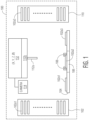
- FIG. 1 illustrates an ultrasonic welding system 100.
- Ultrasonic welding system 100 includes an input workpiece supply 102 for providing a workpiece 102a1, where input workpiece supply 102 is configured to carry a plurality of workpieces 102a1 (e.g., supply 102 may be a carrier such as a magazine handler for carrying a plurality of workpieces 102a1, or other supply structure suitable for the application specific workpiece, etc.).
- Exemplary workpieces 102a1 carried by input workpiece supply 102 include power modules, components of power modules, lead frames, battery modules, etc.
- Workpieces 102a1 are provided (by any desired transport assembly which may be included in a material handling system 104, such as a gripper assembly) from input workpiece supply 102 to a material handling system 104.
- Material handling system 104 moves the workpiece 102a1 (e.g., using a conveyor assembly, using a gripper assembly, etc.) from the input workpiece supply 102 to the support structure 106.
- Support structure 106 supports the workpiece (now labelled as clamped workpiece 102a2, when clamped against support structure 106 using workpiece clamp 108) during a welding operation.
- Output workpiece supply 110 is configured to receive workpieces 102a3 after processing by weld head assembly 112 (where weld head assembly 112 includes an ultrasonic converter 112b carrying a sonotrode 112a).
- Output workpiece supply 110 may be a carrier such as a magazine handler for carrying a plurality of welded workpieces 102a3, or other supply structure suitable for the application specific workpiece.
- Ultrasonic welding system 100 includes a weld head assembly 112.
- Weld head assembly includes an ultrasonic converter 112b carrying a sonotrode 112a, and is moveable along a plurality of substantially horizontal axes.
- weld head assembly 112 is configured to move along the x-axis and the y-axis of ultrasonic welding system 100 (see example x-axis and y-axis on FIG. 2 ).
- weld head assembly 112 is also configured to move along the z-axis of ultrasonic welding system 100, and about a theta axis ( ⁇ -axis) of ultrasonic welding system 100.
- sonotrode 112a is able to be moved into proper welding positions with respect to clamped workpiece 102a2.
- Camera 114 is also provided (where camera may optionally be carried by weld head assembly 112, or may be carried by another part of ultrasonic welding system 100) for imaging operations related to the alignment between sonotrode 112a and clamped workpiece 102a2, the alignment of the components of clamped workpiece 102a2 in itself, optical inspection of the welds after welding operation, etc.
- exemplary technical specifications include: (i) the sonotrode being configured to operate at a bond force of between 5-500 kg, or the sonotrode being configured to operate at a bond force of between 5-300 kg, or the sonotrode being configured to operate at a bond force of between 5-100 kg; (ii) the sonotrode tip motion amplitude being between 5-150 microns, or the sonotrode tip motion amplitude being between 5-120 microns, or the sonotrode tip motion amplitude being between 5-100 microns; (iii) the sonotrode being configured to form an ultrasonic weld between a first portion of a workpiece and a second portion of a workpiece having an area in a range between 1.5-30 mm 2 ; or the sonotrode being configured to form an ultrasonic weld between a first portion of a workpiece and a second portion of a workpiece having an area in a range between 1.5-20 mm 2 ; or the sonotrode being configured to
- FIG. 2 is an overhead view of the elements of ultrasonic welding system 100 shown in FIG. 1 .
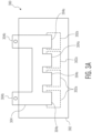
- FIGS. 3A-3B illustrate an example of such workpieces - where workpiece 300 of FIG. 3A is an example of workpiece 102a1 in FIG. 1 .
- the first portion of the workpiece 300 is a contact element 304 including a plurality of conductive contacts 304a (and contact element 304 also includes external contacts 304b configured for connection to an external circuit), and the second portion of the workpiece is a base structure 302 including a plurality of conductive regions 302a.
- contact element 304 is already provided on base structure 302. Specifically, conductive contacts 304a are aligned with conductive regions 302a, and are ready for welding.
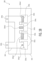
- FIG. 3B illustrates workpiece 300 from FIG. 3A , but with 4 examples of different ultrasonic welds having been formed.
- a first ultrasonic weld 304a1 is formed between a conductive contact 304a and a respective conductive region 302a, where ultrasonic weld 304a1 is formed using ultrasonic torsional motion (thereby forming a substantially round ultrasonic weld 304a1).
- ultrasonic motion other than torsional motion
- Ultrasonic welds 304a2 and 304a3 can also be formed by torsional ultrasonic motion (e.g., torsional ultrasonic motion may, of course, be used to form non-round ultrasonic welds).
- the fourth ultrasonic weld 304a4 formed using linear or torsional motion, covers the conductive contact area to three of its edges. Besides linear and torsional ultrasonic motion, combinations of both can be used.
- input workpiece supply 102 includes workpieces 102a1 including each of a first portion and a second portion, already assembled together, and ready for welding.
- workpieces 102a1 may be workpiece 300 from FIG. 3A including a first portion (contact element 304) assembled together with a second portion (base structure 302), and ready for welding.
- the first portion of a workpiece e.g., a contact element
- the second portion e.g., a base structure
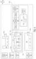
- ultrasonic welding system 400 includes a contact element supply 450 (e.g., a magazine or other supply including a plurality of contact elements 304) and a base structure supply 452 (e.g., a magazine or other supply including a plurality of base structures 302).
- Ultrasonic welding system 400 also includes a workpiece assembly station 454 for assembling contact elements 304 with respective base structures 452. More specifically, a base structure removal tool 452a removes a base structure 302 from base structure supply 452, and moves the base structure 302 to support structure 454a of workpiece assembly station 454.
- base structure removal tool 452a may be a gripper type tool configured to move along the x-axis, the y-axis, and a z-axis.
- a contact element removal tool 450a removes a contact element 304 from contact element supply 450, and moves the contact element 304 to support structure 454a (on top of base structure 302).
- contact element removal tool 450a may be a gripper type tool configured to move along the x-axis, the y-axis, and a z-axis.
- assembly clamp 454b is used to keep contact element 300 positioned relative to base structure 302.
- Camera 458 is according to the present invention used to help with and ensure proper alignment of contact element 304 to base structure 302.
- Assembly tool 456 may provide further assembly functions (e.g., pressing, adhesive distribution, etc.).
- the assembled workpiece 300 (now labelled as workpiece 300a1 in FIG. 4 ) is provided to material handling system 404 (substantially similar to material handling system 104 of FIG. 1 ).
- the workpiece 300 is then moved to support structure 406 (substantially similar to support structure 106 of FIG. 1 ).
- Workpiece clamp 408 (substantially similar to workpiece clamp 108 of FIG. 1 ) secures clamped workpiece 300a2 against support structure 406.
- Sonotrode 412a (substantially similar to sonotrode 112a of FIG.
- ultrasonic converter 412b (where converter 412b is included in weld head assembly 412), and ultrasonically welds conductive contacts (of contact element 300 of workpiece 300a2) to conductive regions (of base structure 302 of workpiece 300a2), using camera 414 (substantially similar to camera 114 of FIG. 1 ) for alignment.
- camera 414 substantially similar to camera 114 of FIG. 1
- the now welded workpiece 300a3 is moved to output workpiece supply 410 (substantially similar to output workpiece supply 110 of FIG. 1 ).
- weld head assembly 412 of ultrasonic welding system 400 may be substantially similar to that described above with respect to weld head assembly 112 of ultrasonic welding system 100 of FIGS. 1-2 .
- the exemplary technical specifications described herein e.g., the exemplary ranges for each of operational bond force of the sonotrode, sonotrode tip motion amplitude, ultrasonic weld area, and operational frequency of the sonotrode, conductive contact thicknesses, etc.
- the ultrasonic welding systems of FIGS. 1-2 and FIG. 4 are equally applicable to the ultrasonic welding systems of FIGS. 1-2 and FIG. 4 , as well as any other ultrasonic welding system within the scope of the invention.
Landscapes
- Engineering & Computer Science (AREA)
- Mechanical Engineering (AREA)
- Physics & Mathematics (AREA)
- Optics & Photonics (AREA)
- Pressure Welding/Diffusion-Bonding (AREA)
- Manufacturing Of Electrical Connectors (AREA)
Description
- The invention relates to the ultrasonic welding, and more particularly, to an ultrasonic welding system, and a method of operating an ultrasonic welding system according to the preamble of claims 1 and 2 respectively (see for example
US 2008/131758 A1 ). - Ultrasonic energy is widely used in forming interconnections between two or more materials. For examples, wire bonding machines (e.g., ball bonding machines, wedge bonding machines, ribbon bonding machines, etc.) are used to bond a wire or ribbon to a bonding location. However, wire bonding utilizes relatively low levels of energy (e.g., bond force, ultrasonic energy, etc.). Exemplary wire bonding machines are marketed by Kulicke and Soffa Industries, Inc. of Fort Washington, Pennsylvania.
- Certain applications involve joining of materials other than wire. Welding has been considered for such applications. Ultrasonic welding is also a widely used technology. Ultrasonic welding may use an ultrasonic converter (e.g., carrying a sonotrode) for converting electrical energy into mechanical movement/scrub (e.g., linear movement/scrub, torsional movement/scrub, etc.). However, existing ultrasonic welding technology and equipment is limited in its ability to provide solutions that can satisfy market demand in terms of cost, operational efficiency, flexibility, portability, and related factors.
- Thus, it would be desirable to improve ultrasonic welding technology to overcome existing barriers to potential markets.
- According to a first aspect of the present invention, an ultrasonic welding system is defined in claim 1.
- The ultrasonic welding system includes a support structure for supporting a workpiece. The ultrasonic welding system also includes a weld head assembly including an ultrasonic converter carrying a sonotrode. The weld head assembly is moveable along a plurality of substantially horizontal axes. The sonotrode is configured to operate during a welding operation at a bond force of between 5-500 kg, and with a sonotrode tip motion amplitude of between 5-150 microns.
- According to a second aspect of the present invention, method of operating an ultrasonic welding system is defined in claim 2.
- The method includes the steps of: (a) supporting a workpiece on a support structure of the ultrasonic welding system; and (b) welding a first portion of the workpiece to a second portion of the workpiece using a weld head assembly including an ultrasonic converter carrying a sonotrode, the weld head assembly being moveable along a plurality of substantially horizontal axes, the sonotrode being configured to weld the first portion of the workpiece to the second portion of the workpiece during a welding operation at a bond force of between 5-500 kg, and with a sonotrode tip motion amplitude of between 5-150 microns.
- Further preferred embodiments of the present invention are defined in the dependent claims.
- The invention is best understood from the following detailed description when read in connection with the accompanying drawings. It is emphasized that, according to common practice, the various features of the drawings are not to scale. On the contrary, the dimensions of the various features are arbitrarily expanded or reduced for clarity. Included in the drawings are the following figures:
-
FIG. 1 is a block diagram side view of an ultrasonic welding system in accordance with an exemplary embodiment of the invention; -
FIG. 2 is a block diagram top view of the ultrasonic welding system ofFIG. 1 ; -
FIG. 3A is a block diagram top view of a workpiece configured for welding using ultrasonic welding systems in accordance with various exemplary embodiments of the invention; -
FIG. 3B is a block diagram top view of the workpiece ofFIG. 3A including exemplary welded connections in accordance with various exemplary embodiments of the invention; and -
FIG. 4 is a block diagram top view of another ultrasonic welding system in accordance with another exemplary embodiment of the invention. - In accordance with the invention, ultrasonic welding capability is provided in welding systems (and corresponding methods) that may achieve efficient volume production. Aspects of the invention relate to cameras (e.g., for pattern recognition), process diagnostics, material handling and fixturing / clamping systems, cleaning (debris removal) systems, (optical) inspection systems, amongst others.
-
FIG. 1 illustrates anultrasonic welding system 100.Ultrasonic welding system 100 includes aninput workpiece supply 102 for providing a workpiece 102a1, whereinput workpiece supply 102 is configured to carry a plurality of workpieces 102a1 (e.g.,supply 102 may be a carrier such as a magazine handler for carrying a plurality of workpieces 102a1, or other supply structure suitable for the application specific workpiece, etc.). Exemplary workpieces 102a1 carried byinput workpiece supply 102 include power modules, components of power modules, lead frames, battery modules, etc. Workpieces 102a1 are provided (by any desired transport assembly which may be included in amaterial handling system 104, such as a gripper assembly) frominput workpiece supply 102 to amaterial handling system 104.Material handling system 104 moves the workpiece 102a1 (e.g., using a conveyor assembly, using a gripper assembly, etc.) from theinput workpiece supply 102 to thesupport structure 106.Support structure 106 supports the workpiece (now labelled as clamped workpiece 102a2, when clamped againstsupport structure 106 using workpiece clamp 108) during a welding operation. After the welding operation (described below with respect to weld head assembly 112), the now welded workpiece 102a3 is moved (e.g., using a conveyor assembly, using a gripper assembly, etc.) from a portion ofmaterial handling 104 downstream ofsupport structure 106, to anoutput workpiece supply 110.Output workpiece supply 110 is configured to receive workpieces 102a3 after processing by weld head assembly 112 (whereweld head assembly 112 includes anultrasonic converter 112b carrying asonotrode 112a).Output workpiece supply 110 may be a carrier such as a magazine handler for carrying a plurality of welded workpieces 102a3, or other supply structure suitable for the application specific workpiece. -
Ultrasonic welding system 100 includes aweld head assembly 112. Weld head assembly includes anultrasonic converter 112b carrying asonotrode 112a, and is moveable along a plurality of substantially horizontal axes. In the example shown inFIG. 1 ,weld head assembly 112 is configured to move along the x-axis and the y-axis of ultrasonic welding system 100 (see example x-axis and y-axis onFIG. 2 ). In the example shown inFIG. 1 ,weld head assembly 112 is also configured to move along the z-axis ofultrasonic welding system 100, and about a theta axis (Ø-axis) ofultrasonic welding system 100. Using the motion axes ofweld head assembly 112,sonotrode 112a is able to be moved into proper welding positions with respect to clamped workpiece 102a2.Camera 114 is also provided (where camera may optionally be carried byweld head assembly 112, or may be carried by another part of ultrasonic welding system 100) for imaging operations related to the alignment betweensonotrode 112a and clamped workpiece 102a2, the alignment of the components of clamped workpiece 102a2 in itself, optical inspection of the welds after welding operation, etc. - According to certain exemplary embodiments of the invention, during the welding operations, exemplary technical specifications include: (i) the sonotrode being configured to operate at a bond force of between 5-500 kg, or the sonotrode being configured to operate at a bond force of between 5-300 kg, or the sonotrode being configured to operate at a bond force of between 5-100 kg; (ii) the sonotrode tip motion amplitude being between 5-150 microns, or the sonotrode tip motion amplitude being between 5-120 microns, or the sonotrode tip motion amplitude being between 5-100 microns; (iii) the sonotrode being configured to form an ultrasonic weld between a first portion of a workpiece and a second portion of a workpiece having an area in a range between 1.5-30 mm2; or the sonotrode being configured to form an ultrasonic weld between a first portion of a workpiece and a second portion of a workpiece having an area in a range between 1.5-20 mm2; or the sonotrode being configured to form an ultrasonic weld between a first portion of a workpiece and a second portion of a workpiece having an area in a range between 1.5-16 mm2; and (iv) the sonotrode being configured to operate at a frequency in a range between 15-40 kHz, or the sonotrode being configured to operate at a frequency in a range between 20-35 kHz, or the sonotrode being configured to operate at a frequency in a range between 20-30 kHz. Exemplary thicknesses of the conductive contact of the contact element (the part of the workpiece being contacted by the sonotrode) include: between 0.2-3 mm; 0.2-1.5 mm, and 0.2-1.2 mm.
-
FIG. 2 is an overhead view of the elements ofultrasonic welding system 100 shown inFIG. 1 . - Various types of workpieces may be welded using ultrasonic welding system 100 (or other systems with the scope of the invention). Such workpieces may include a first portion of the workpiece configured to be welded to a second portion of the workpiece.
FIGS. 3A-3B illustrate an example of such workpieces - whereworkpiece 300 ofFIG. 3A is an example of workpiece 102a1 inFIG. 1 . In the example ofFIG. 3A , the first portion of theworkpiece 300 is acontact element 304 including a plurality ofconductive contacts 304a (andcontact element 304 also includesexternal contacts 304b configured for connection to an external circuit), and the second portion of the workpiece is abase structure 302 including a plurality ofconductive regions 302a. In the example ofFIG. 3A ,contact element 304 is already provided onbase structure 302. Specifically,conductive contacts 304a are aligned withconductive regions 302a, and are ready for welding. - After positioning
workpiece 300 on a support structure (e.g.,support structure 106 ofultrasonic welding system 100 inFIG. 1 ), a sonotrode is used to form ultrasonic welds.FIG. 3B illustratesworkpiece 300 fromFIG. 3A , but with 4 examples of different ultrasonic welds having been formed. A first ultrasonic weld 304a1 is formed between aconductive contact 304a and a respectiveconductive region 302a, where ultrasonic weld 304a1 is formed using ultrasonic torsional motion (thereby forming a substantially round ultrasonic weld 304a1). Of course, other types of ultrasonic motion (other than torsional motion) are contemplated. For example,FIG. 3B illustrates a second ultrasonic weld 304a2 (formed using linear ultrasonic motion, for example, along an x-axis), and a third ultrasonic weld 304a3 (formed using linear ultrasonic motion, for example, along a y-axis that is substantially perpendicular to the x-axis). Ultrasonic welds 304a2 and 304a3 can also be formed by torsional ultrasonic motion (e.g., torsional ultrasonic motion may, of course, be used to form non-round ultrasonic welds). The fourth ultrasonic weld 304a4, formed using linear or torsional motion, covers the conductive contact area to three of its edges. Besides linear and torsional ultrasonic motion, combinations of both can be used. - Referring again back to
FIG. 1 ,input workpiece supply 102 includes workpieces 102a1 including each of a first portion and a second portion, already assembled together, and ready for welding. For example, workpieces 102a1 may be workpiece 300 fromFIG. 3A including a first portion (contact element 304) assembled together with a second portion (base structure 302), and ready for welding. However, according to certain embodiments of the invention, the first portion of a workpiece (e.g., a contact element) may not be assembled together with the second portion (e.g., a base structure) at the start of processing by the ultrasonic welding system.FIG. 4 illustrates such a system. - Referring now to
FIG. 4 ,ultrasonic welding system 400 includes a contact element supply 450 (e.g., a magazine or other supply including a plurality of contact elements 304) and a base structure supply 452 (e.g., a magazine or other supply including a plurality of base structures 302).Ultrasonic welding system 400 also includes aworkpiece assembly station 454 for assemblingcontact elements 304 withrespective base structures 452. More specifically, a basestructure removal tool 452a removes abase structure 302 frombase structure supply 452, and moves thebase structure 302 to supportstructure 454a ofworkpiece assembly station 454. For example, basestructure removal tool 452a may be a gripper type tool configured to move along the x-axis, the y-axis, and a z-axis. Likewise, a contactelement removal tool 450a removes acontact element 304 fromcontact element supply 450, and moves thecontact element 304 to supportstructure 454a (on top of base structure 302). For example, contactelement removal tool 450a may be a gripper type tool configured to move along the x-axis, the y-axis, and a z-axis. Once aligned / assembled,assembly clamp 454b is used to keepcontact element 300 positioned relative tobase structure 302.Camera 458 is according to the present invention used to help with and ensure proper alignment ofcontact element 304 tobase structure 302.Assembly tool 456 may provide further assembly functions (e.g., pressing, adhesive distribution, etc.). - After processing (and assembly) at
workpiece assembly station 454, the assembled workpiece 300 (now labelled as workpiece 300a1 inFIG. 4 ) is provided to material handling system 404 (substantially similar tomaterial handling system 104 ofFIG. 1 ). Theworkpiece 300 is then moved to support structure 406 (substantially similar to supportstructure 106 ofFIG. 1 ). Workpiece clamp 408 (substantially similar toworkpiece clamp 108 ofFIG. 1 ) secures clamped workpiece 300a2 againstsupport structure 406.Sonotrode 412a (substantially similar to sonotrode 112a ofFIG. 1 ) is carried byultrasonic converter 412b (whereconverter 412b is included in weld head assembly 412), and ultrasonically welds conductive contacts (ofcontact element 300 of workpiece 300a2) to conductive regions (ofbase structure 302 of workpiece 300a2), using camera 414 (substantially similar tocamera 114 ofFIG. 1 ) for alignment. After welding, the now welded workpiece 300a3 is moved to output workpiece supply 410 (substantially similar tooutput workpiece supply 110 ofFIG. 1 ). - The operation of
weld head assembly 412 ofultrasonic welding system 400 may be substantially similar to that described above with respect toweld head assembly 112 ofultrasonic welding system 100 ofFIGS. 1-2 . Further, the exemplary technical specifications described herein (e.g., the exemplary ranges for each of operational bond force of the sonotrode, sonotrode tip motion amplitude, ultrasonic weld area, and operational frequency of the sonotrode, conductive contact thicknesses, etc.) are equally applicable to the ultrasonic welding systems ofFIGS. 1-2 andFIG. 4 , as well as any other ultrasonic welding system within the scope of the invention. - Although the invention is illustrated and described herein with reference to specific embodiments, the invention is not intended to be limited to the details shown.
- Rather, various modifications may be made in the details within the scope of the present invention as defined in the appended claims.
Claims (14)
- An ultrasonic welding system (100, 400) comprising:a support structure (106, 406) for supporting a workpiece (102a1, 300, 300a1);a weld head assembly (112, 412) including an ultrasonic converter carrying a sonotrode (112a, 412a), the sonotrode being configured to operate during a welding operation at a bond force of between 5-500 kg, and with a sonotrode tip motion amplitude of between 5-150 microns;the system (100, 400) being characterised by:the weld head assembly being movable along a plurality of substantially horizontal axes;a camera (114, 414), said camera preferably being carried by the weld head assembly, for imaging operations related to the alignment between sonotrode and clamped workpiece.
- A method of operating an ultrasonic welding system (100, 400), the method comprising the steps of:supporting a workpiece (102a1, 300, 300a1) on a support structure of the ultrasonic welding system; andthe method being characterised by the following:welding a first portion of the workpiece to a second portion of the workpiece using a weld head assembly (112, 412) including an ultrasonic converter carrying a sonotrode (112a, 412a), the weld head assembly being moveable along a plurality of substantially horizontal axes, the sonotrode being configured to weld the first portion of the workpiece to the second portion of the workpiece during a welding operation at a bond force of between 5-500 kg, and with a sonotrode tip motion amplitude of between 5-150 microns; whereina camera (114, 414) is used for imaging operations related to the alignment between sonotrode and clamped workpiece, said camera preferably being carried by the weld head assembly.
- The ultrasonic welding system (100, 400) of claim 1 or the method of claim 2, wherein the sonotrode (112a, 412a) is configured to weld a first portion of the workpiece to a second portion of the workpiece using at least one of linear ultrasonic motion and torsional ultrasonic motion.
- The ultrasonic welding system (100, 400) of claim 1 or the method of claim 2, further comprising an input workpiece supply for providing the workpiece (102a1, 300, 300a1), the input workpiece supply being configured to carry a plurality of workpieces.
- The ultrasonic welding system (100, 400) of claim 3 or the method of claim 3, further comprising a material handling system for moving the workpiece (102a1, 300, 300a1) from the input workpiece supply to the support structure (106, 406).
- The ultrasonic welding system (100, 400) of claim 1 or the method of claim 2, further comprising an output workpiece supply for receiving the workpiece (102a1, 300, 300a1) after processing by the sonotrode (112a, 412a).
- The method of claim 2, wherein the workpiece (102a1, 300, 300a1) is selected from the group consisting of a power module, a lead frame and a battery module.
- The method of claim 2, wherein the workpiece (102a1, 300, 300a1) includes a contact element and a base structure, wherein the sonotrode (112a, 412a) is configured to ultrasonically weld at least one conductive contact of the contact element to a respective conductive region of the base structure.
- The ultrasonic welding system (100, 400) of claim 1 or the method of claim 2, wherein the plurality of substantially horizontal axes include an x-axis and a y-axis of the ultrasonic welding system.
- The ultrasonic welding system (100, 400) of claim 1 or the method of claim 2, further comprising a workpiece clamping system for clamping the workpiece (102a1, 300, 300a1) to the support structure (106, 406) during ultrasonic welding by the sonotrode.
- The ultrasonic welding system (100, 400) of claim 1 or the method of claim 2, further comprising a workpiece assembly station configured to assemble the workpiece before ultrasonic welding of the workpiece (102a1, 300, 300a1) by the sonotrode (112a, 412a), the workpiece assembly station being configured to align a contact element of the workpiece to a base structure of the workpiece.
- The ultrasonic welding system (100, 400) of claim 10 or the method of claim 10, wherein, after assembly of the workpiece (102a1, 300, 300a1) at the workpiece assembly station, the sonotrode (112a, 412a) is configured to ultrasonically weld at least one conductive contact of the contact element to a respective conductive region of the base structure.
- The ultrasonic welding system (100, 400) of claim 1 or the method of claim 2, wherein the sonotrode is configured to form an ultrasonic weld between the first portion of the workpiece and the second portion of the workpiece (102a1, 300, 300a1) having an area in a range between 1.5-30 mm2
- The ultrasonic welding system (100, 400) of claim 1 or the method of claim 2, wherein the sonotrode (112a, 412a) is configured to operate at a frequency in a range between 15-40 kHz.
Priority Applications (1)
| Application Number | Priority Date | Filing Date | Title |
|---|---|---|---|
| EP25181290.5A EP4681866A3 (en) | 2017-04-04 | 2018-04-03 | Ultrasonic welding system and method of operating an ultrasonic welding system |
Applications Claiming Priority (3)
| Application Number | Priority Date | Filing Date | Title |
|---|---|---|---|
| US201762481408P | 2017-04-04 | 2017-04-04 | |
| EP18781172.4A EP3606695B1 (en) | 2017-04-04 | 2018-04-03 | Ultrasonic welding system and method of operating an ultrasonic welding system |
| PCT/US2018/025941 WO2018187364A1 (en) | 2017-04-04 | 2018-04-03 | Ultrasonic welding systems and methods of using the same |
Related Parent Applications (1)
| Application Number | Title | Priority Date | Filing Date |
|---|---|---|---|
| EP18781172.4A Division EP3606695B1 (en) | 2017-04-04 | 2018-04-03 | Ultrasonic welding system and method of operating an ultrasonic welding system |
Related Child Applications (2)
| Application Number | Title | Priority Date | Filing Date |
|---|---|---|---|
| EP25181290.5A Division EP4681866A3 (en) | 2017-04-04 | 2018-04-03 | Ultrasonic welding system and method of operating an ultrasonic welding system |
| EP25181290.5A Previously-Filed-Application EP4681866A3 (en) | 2017-04-04 | 2018-04-03 | Ultrasonic welding system and method of operating an ultrasonic welding system |
Publications (3)
| Publication Number | Publication Date |
|---|---|
| EP4269019A2 EP4269019A2 (en) | 2023-11-01 |
| EP4269019A3 EP4269019A3 (en) | 2024-02-21 |
| EP4269019B1 true EP4269019B1 (en) | 2025-07-09 |
Family
ID=63713546
Family Applications (3)
| Application Number | Title | Priority Date | Filing Date |
|---|---|---|---|
| EP25181290.5A Pending EP4681866A3 (en) | 2017-04-04 | 2018-04-03 | Ultrasonic welding system and method of operating an ultrasonic welding system |
| EP18781172.4A Active EP3606695B1 (en) | 2017-04-04 | 2018-04-03 | Ultrasonic welding system and method of operating an ultrasonic welding system |
| EP23020278.0A Active EP4269019B1 (en) | 2017-04-04 | 2018-04-03 | Ultrasonic welding system and method of operating an ultrasonic welding system |
Family Applications Before (2)
| Application Number | Title | Priority Date | Filing Date |
|---|---|---|---|
| EP25181290.5A Pending EP4681866A3 (en) | 2017-04-04 | 2018-04-03 | Ultrasonic welding system and method of operating an ultrasonic welding system |
| EP18781172.4A Active EP3606695B1 (en) | 2017-04-04 | 2018-04-03 | Ultrasonic welding system and method of operating an ultrasonic welding system |
Country Status (5)
| Country | Link |
|---|---|
| US (2) | US10882134B2 (en) |
| EP (3) | EP4681866A3 (en) |
| JP (1) | JP7181217B2 (en) |
| CN (2) | CN110891726B (en) |
| WO (1) | WO2018187364A1 (en) |
Families Citing this family (9)
| Publication number | Priority date | Publication date | Assignee | Title |
|---|---|---|---|---|
| JP7181217B2 (en) | 2017-04-04 | 2022-11-30 | クリック アンド ソッファ インダストリーズ、インク. | Ultrasonic welding system and method of use |
| EP3887085B1 (en) * | 2018-11-28 | 2024-03-13 | Kulicke and Soffa Industries, Inc. | Ultrasonic welding systems and methods of using the same |
| WO2020129618A1 (en) * | 2018-12-19 | 2020-06-25 | パナソニックIpマネジメント株式会社 | Welding system, and method for welding workpiece in which same is used |
| WO2020250002A1 (en) * | 2019-06-10 | 2020-12-17 | Easy Automation S.R.L. | System for the application of a threadlike element on a substrate |
| CN115697615B (en) * | 2020-06-03 | 2026-05-12 | 库利克和索夫工业公司 | Ultrasonic welding system, method of use thereof, and related workpieces including welded conductive pins |
| WO2024220377A1 (en) | 2023-04-19 | 2024-10-24 | Kulicke And Soffa Industries, Inc. | Ultrasonic welding systems for conductive pins, and related methods |
| US20250187103A1 (en) * | 2023-12-07 | 2025-06-12 | Kulicke And Soffa Industries, Inc. | Conductive pins, power modules, ultrasonic welding systems, and methods of using the same |
| WO2025193479A1 (en) * | 2024-03-15 | 2025-09-18 | Kulicke And Soffa Industries, Inc. | Ultrasonic welding systems, and sonotrodes for ultrasonic welding systems |
| EP4737046A1 (en) * | 2024-11-01 | 2026-05-06 | Samsung SDI Co., Ltd. | Ultrasonic welding device and method for manufacturing secondary battery using ultrasonic welding device |
Citations (24)
| Publication number | Priority date | Publication date | Assignee | Title |
|---|---|---|---|---|
| WO1996001377A1 (en) | 1994-07-01 | 1996-01-18 | Createc Patent Holding S.A. | Method of joining together parts consisting at least partly of wood or wood-like materials |
| US5884831A (en) | 1996-07-05 | 1999-03-23 | Ultex Corporation | Ultrasonic vibration bonding chip mounter |
| US20010016786A1 (en) | 2000-02-10 | 2001-08-23 | Kabushiki Kaisha Shinkawa | Tool position measurement method, offset measurement method, reference member and bonding apparatus |
| DE10101236A1 (en) | 2001-01-12 | 2002-07-25 | Schunk Ultraschalltechnik Gmbh | Method of joining flat cables by ultrasonic vibrations e.g. for motor vehicle electrical systems, involves placing cables on carrier designed partially as counter-electrode |
| US20060169388A1 (en) | 2005-01-28 | 2006-08-03 | Nissan Motor Co., Ltd. | Ultrasonic bonding equipment and resulting bonding structure |
| JP3966765B2 (en) | 2002-05-24 | 2007-08-29 | 松下電器産業株式会社 | Component holding member reproducing apparatus and component mounting method |
| US20080131758A1 (en) | 2006-11-03 | 2008-06-05 | Boris Makovetski | Ultrasonic metal welding techniques and batteries manufactured using such techniques |
| US20080265004A1 (en) | 2005-10-10 | 2008-10-30 | Schunk Ultraschalltechnik Gmbh | Method for Producing a Welded Joint Between Electrical Conductors by Means of an Ultrasonic Welding Method |
| US20100065613A1 (en) | 2007-04-27 | 2010-03-18 | Panasonic Corporation | Electronic component mounting apparatus and electronic component mounting method |
| JP4917957B2 (en) | 2007-04-27 | 2012-04-18 | パナソニック株式会社 | Ultrasonic bonding apparatus and electronic component bonding method |
| KR20120096621A (en) | 2011-02-23 | 2012-08-31 | 주식회사 엘지화학 | Methode and device for inspection of intensity of ultrasonic welding |
| US20130049201A1 (en) | 2011-08-31 | 2013-02-28 | Hitachi, Ltd. | Power Module and Manufacturing Method Thereof |
| US20130112735A1 (en) | 2010-07-19 | 2013-05-09 | Orthodyne Electronics Corporation | Ultrasonic bonding systems including workholder and ribbon feeding system |
| WO2014080053A1 (en) | 2012-11-21 | 2014-05-30 | Manuel Ruiz Carmona | Appliance for joining a sheet-type body to the mouth of a box |
| WO2014198467A1 (en) | 2013-05-13 | 2014-12-18 | Schunk Sonosystems Gmbh | Method for determining the compression level of a node after ultrasonic welding |
| DE102013107637A1 (en) | 2013-07-18 | 2015-01-22 | Schunk Sonosystems Gmbh | Method for producing a knot by welding |
| JP5667601B2 (en) | 2012-06-12 | 2015-02-12 | 三菱電機エンジニアリング株式会社 | Ultrasonic bonding method and ultrasonic bonding apparatus |
| US20150097285A1 (en) | 2013-10-08 | 2015-04-09 | Kulicke And Soffa Industries, Inc. | Systems and methods for bonding semiconductor elements |
| US20150210003A1 (en) | 2014-01-28 | 2015-07-30 | Frito-Lay Noth America, Inc. | Transverse Sonotrode Design for Ultrasonic Welding |
| WO2015117253A1 (en) | 2014-02-04 | 2015-08-13 | Woodwelding Ag | Connector and method of using the same |
| US20160158876A1 (en) | 2014-12-09 | 2016-06-09 | GM Global Technology Operations LLC | Ultrasonic welding of composites using c frame tooling |
| US20160297037A1 (en) | 2010-12-29 | 2016-10-13 | Orthodyne Electronics Corporation | Methods and systems for aligning tooling elements of ultrasonic bonding systems |
| JP2017024040A (en) | 2015-07-22 | 2017-02-02 | 矢崎総業株式会社 | Ultrasonic bonding apparatus |
| WO2018187364A1 (en) | 2017-04-04 | 2018-10-11 | Kulicke And Saffa Industries, Inc. | Ultrasonic welding systems and methods of using the same |
Family Cites Families (69)
| Publication number | Priority date | Publication date | Assignee | Title |
|---|---|---|---|---|
| US3995845A (en) * | 1972-12-26 | 1976-12-07 | Rca Corporation | Ultrasonic wire bonding chuck |
| US3926357A (en) * | 1973-10-09 | 1975-12-16 | Du Pont | Process for applying contacts |
| JPS5530810A (en) * | 1978-08-25 | 1980-03-04 | Fujitsu Ltd | Automatic bonding system for semiconductor device assembling |
| US4301958A (en) * | 1978-08-24 | 1981-11-24 | Fujitsu Limited | Arrangement for automatically fabricating and bonding semiconductor devices |
| US4411721A (en) * | 1982-02-25 | 1983-10-25 | The Mead Corporation | Apparatus and method for attaching fastener tapes |
| US4872052A (en) * | 1986-12-03 | 1989-10-03 | View Engineering, Inc. | Semiconductor device inspection system |
| JP2555876B2 (en) * | 1988-06-29 | 1996-11-20 | 日本電気株式会社 | Inner lead bonding equipment |
| JPH081920B2 (en) * | 1990-06-08 | 1996-01-10 | 株式会社東芝 | Wire bonding equipment |
| US5614057A (en) * | 1992-02-19 | 1997-03-25 | Mim Industries, Inc. | Automatic ultrasonic fusing system |
| US5427301A (en) * | 1994-05-06 | 1995-06-27 | Ford Motor Company | Ultrasonic flip chip process and apparatus |
| JPH0820071A (en) * | 1994-07-07 | 1996-01-23 | Kiyoshi Shinoda | Ultrasonic welding apparatus |
| JP3455344B2 (en) * | 1995-10-20 | 2003-10-14 | 株式会社オートネットワーク技術研究所 | Ultrasonic welding equipment |
| JP3354063B2 (en) * | 1996-11-29 | 2002-12-09 | 株式会社新川 | Lead frame supply method and supply device |
| US6787391B1 (en) * | 1998-06-19 | 2004-09-07 | Matsushita Electric Industrial Co., Ltd. | Method of forming bumps on a wafer utilizing a post-heating operation, and apparatus therefor |
| JP2000068327A (en) * | 1998-08-20 | 2000-03-03 | Matsushita Electric Ind Co Ltd | Component mounting method and equipment |
| US20050145306A1 (en) * | 1998-09-03 | 2005-07-07 | Uit, L.L.C. Company | Welded joints with new properties and provision of such properties by ultrasonic impact treatment |
| US6820792B2 (en) * | 1998-09-30 | 2004-11-23 | Samsung Electronics Co., Ltd. | Die bonding equipment |
| JP3290632B2 (en) * | 1999-01-06 | 2002-06-10 | 株式会社アルテクス | Ultrasonic vibration bonding equipment |
| JP4128319B2 (en) * | 1999-12-24 | 2008-07-30 | 株式会社新川 | Multi-chip bonding method and apparatus |
| US6616030B2 (en) * | 2001-05-07 | 2003-09-09 | West Bond, Inc. | Gantry mounted ultrasonic wire bonder with orbital bonding tool head |
| US7819302B2 (en) * | 2004-09-30 | 2010-10-26 | The Boeing Company | Aluminum end caps ultrasonically welded to end of aluminum tube |
| JP2006135249A (en) * | 2004-11-09 | 2006-05-25 | Fujitsu Ltd | Ultrasonic mounting method and ultrasonic mounting apparatus used therefor |
| JP4539454B2 (en) * | 2005-06-20 | 2010-09-08 | パナソニック株式会社 | Electronic component thermocompression bonding tool, electronic component mounting apparatus, and mounting method |
| JP4577509B2 (en) | 2005-06-22 | 2010-11-10 | トヨタ自動車株式会社 | Power semiconductor module and manufacturing method thereof |
| US7568606B2 (en) * | 2006-10-19 | 2009-08-04 | Asm Technology Singapore Pte Ltd. | Electronic device handler for a bonding apparatus |
| JP5278311B2 (en) * | 2007-03-28 | 2013-09-04 | 富士通株式会社 | Ultrasonic bonding apparatus and ultrasonic bonding method |
| TW200925092A (en) * | 2007-10-03 | 2009-06-16 | Panasonic Corp | Apparatus for bonding adhesive tape, and method for connecting tape member |
| JP5313751B2 (en) * | 2008-05-07 | 2013-10-09 | パナソニック株式会社 | Electronic component mounting device |
| JP5281550B2 (en) * | 2008-12-08 | 2013-09-04 | パナソニック株式会社 | Bonding tool, electronic component mounting apparatus, and electronic component mounting method |
| JP5099064B2 (en) * | 2009-04-07 | 2012-12-12 | パナソニック株式会社 | Electronic component mounting system and electronic component mounting method |
| US7810699B1 (en) * | 2009-04-22 | 2010-10-12 | Gm Global Technology Operations, Inc. | Method and system for optimized vibration welding |
| US9038688B2 (en) * | 2009-04-29 | 2015-05-26 | Covidien Lp | System and method for making tapered looped suture |
| WO2011137269A2 (en) * | 2010-04-30 | 2011-11-03 | Orthodyne Electronics Corporation | Ultrasonic bonding systems and methods of using the same |
| JP5426762B2 (en) * | 2010-05-20 | 2014-02-26 | パナソニック株式会社 | Bonding tool, electronic component mounting apparatus, and method of manufacturing bonding tool |
| JP2012024790A (en) | 2010-07-21 | 2012-02-09 | Yazaki Corp | Ultrasonic welding device |
| JP5686555B2 (en) * | 2010-09-08 | 2015-03-18 | 富士機械製造株式会社 | Manufacturing system construction method |
| US8231044B2 (en) * | 2010-10-01 | 2012-07-31 | Orthodyne Electronics Corporation | Solar substrate ribbon bonding system |
| US8196798B2 (en) * | 2010-10-08 | 2012-06-12 | Kulicke And Soffa Industries, Inc. | Solar substrate ribbon bonding system |
| KR20130051498A (en) * | 2010-10-13 | 2013-05-20 | 에이비비 리써치 리미티드 | Semiconductor module and method of manufacturing a semiconductor module |
| US9272802B2 (en) * | 2010-10-26 | 2016-03-01 | Rinco Ultrasonics USA, Inc. | Stepped sonotrode and anvil energy director grids for narrow/complex ultrasonic welds of improved durability |
| JP5747164B2 (en) * | 2011-09-27 | 2015-07-08 | パナソニックIpマネジメント株式会社 | Electronic component mounting system |
| KR101369312B1 (en) * | 2012-07-24 | 2014-03-04 | 주식회사 알리 | Ultrasonic welding device for lamp casing for vehicle |
| JP6033011B2 (en) | 2012-09-12 | 2016-11-30 | 三菱電機株式会社 | Power semiconductor device and method for manufacturing power semiconductor device |
| CN102861984B (en) * | 2012-10-09 | 2015-06-24 | 雷广伟 | Four-head ultrasonic welding equipment for positive and negative poles of power battery |
| US20140110833A1 (en) * | 2012-10-24 | 2014-04-24 | Samsung Electro-Mechanics Co., Ltd. | Power module package |
| EP2769919A4 (en) * | 2012-11-21 | 2015-05-20 | Carmona Manuel Ruiz | Appliance for joining a sheet-type body to the mouth of a box |
| DE102013208749B4 (en) | 2013-05-13 | 2015-11-19 | Schunk Sonosystems Gmbh | Ultrasonic welding device and method for welding components by means of an ultrasonic welding device |
| CN105637675B (en) * | 2013-10-03 | 2018-03-30 | 日产自动车株式会社 | Separator engagement device for electrical equipment |
| JP6143884B2 (en) * | 2013-11-26 | 2017-06-07 | 三菱電機株式会社 | Power module |
| JP6091443B2 (en) | 2014-01-31 | 2017-03-08 | 三菱電機株式会社 | Semiconductor module |
| EP3196927B1 (en) * | 2014-07-02 | 2019-04-17 | Mitsubishi Materials Corporation | Joined body manufacturing method |
| JP6488917B2 (en) * | 2014-07-04 | 2019-03-27 | 三菱マテリアル株式会社 | Power module substrate with heat sink and power module |
| JP6406983B2 (en) | 2014-11-12 | 2018-10-17 | 三菱電機株式会社 | Semiconductor device and manufacturing method thereof |
| US9475232B2 (en) * | 2014-12-01 | 2016-10-25 | Zee.Aero Inc. | Damping and isolating vibration during ultrasonic welding |
| WO2016136457A1 (en) * | 2015-02-25 | 2016-09-01 | 三菱電機株式会社 | Power module |
| KR101619782B1 (en) * | 2015-04-14 | 2016-05-12 | 제엠제코(주) | Apparatus for bonding the semiconductor substrate by ultrasonic welding |
| DE112016002608T5 (en) | 2015-06-11 | 2018-03-08 | Mitsubishi Electric Corporation | A method of manufacturing a power semiconductor device and power semiconductor device |
| CN204991892U (en) * | 2015-09-14 | 2016-01-20 | 福建亚亨动力科技集团有限公司 | Automatic production line of blocking a shot of battery |
| JP6480595B2 (en) * | 2015-09-29 | 2019-03-13 | 東芝三菱電機産業システム株式会社 | Ultrasonic vibration bonding equipment |
| KR102490863B1 (en) * | 2015-11-04 | 2023-01-20 | 삼성에스디아이 주식회사 | Manufacturing method for secondary battery |
| KR101734712B1 (en) * | 2015-12-09 | 2017-05-11 | 현대자동차주식회사 | Power module |
| WO2017132352A1 (en) * | 2016-01-27 | 2017-08-03 | Ensync, Inc. | Process for joining incompatible materials and materials formed thereby |
| JP6685143B2 (en) * | 2016-02-03 | 2020-04-22 | 三菱電機株式会社 | Electrode terminal, semiconductor device and power converter |
| CN107546214B (en) * | 2016-06-23 | 2020-02-07 | 台达电子工业股份有限公司 | Power module packaging structure |
| CN109526212B (en) * | 2016-08-04 | 2021-03-23 | 东芝三菱电机产业系统株式会社 | Ultrasonic bonding tool and ultrasonic bonding device |
| TWI599664B (en) * | 2016-09-13 | 2017-09-21 | 樂金股份有限公司 | Metal strip for power module packaging |
| US10471545B2 (en) * | 2016-11-23 | 2019-11-12 | Rohinni, LLC | Top-side laser for direct transfer of semiconductor devices |
| JP2020537330A (en) * | 2017-10-13 | 2020-12-17 | クリック アンド ソッファ インダストリーズ、インク. | How to assemble conductive terminals, busbars, their manufacturing methods, and related power modules |
| EP3887085B1 (en) * | 2018-11-28 | 2024-03-13 | Kulicke and Soffa Industries, Inc. | Ultrasonic welding systems and methods of using the same |
-
2018
- 2018-04-03 JP JP2019554509A patent/JP7181217B2/en active Active
- 2018-04-03 US US16/321,635 patent/US10882134B2/en active Active
- 2018-04-03 EP EP25181290.5A patent/EP4681866A3/en active Pending
- 2018-04-03 EP EP18781172.4A patent/EP3606695B1/en active Active
- 2018-04-03 EP EP23020278.0A patent/EP4269019B1/en active Active
- 2018-04-03 CN CN201880023804.XA patent/CN110891726B/en active Active
- 2018-04-03 CN CN202111073625.7A patent/CN113681145B/en active Active
- 2018-04-03 WO PCT/US2018/025941 patent/WO2018187364A1/en not_active Ceased
-
2020
- 2020-11-25 US US17/104,711 patent/US11364565B2/en active Active
Patent Citations (24)
| Publication number | Priority date | Publication date | Assignee | Title |
|---|---|---|---|---|
| WO1996001377A1 (en) | 1994-07-01 | 1996-01-18 | Createc Patent Holding S.A. | Method of joining together parts consisting at least partly of wood or wood-like materials |
| US5884831A (en) | 1996-07-05 | 1999-03-23 | Ultex Corporation | Ultrasonic vibration bonding chip mounter |
| US20010016786A1 (en) | 2000-02-10 | 2001-08-23 | Kabushiki Kaisha Shinkawa | Tool position measurement method, offset measurement method, reference member and bonding apparatus |
| DE10101236A1 (en) | 2001-01-12 | 2002-07-25 | Schunk Ultraschalltechnik Gmbh | Method of joining flat cables by ultrasonic vibrations e.g. for motor vehicle electrical systems, involves placing cables on carrier designed partially as counter-electrode |
| JP3966765B2 (en) | 2002-05-24 | 2007-08-29 | 松下電器産業株式会社 | Component holding member reproducing apparatus and component mounting method |
| US20060169388A1 (en) | 2005-01-28 | 2006-08-03 | Nissan Motor Co., Ltd. | Ultrasonic bonding equipment and resulting bonding structure |
| US20080265004A1 (en) | 2005-10-10 | 2008-10-30 | Schunk Ultraschalltechnik Gmbh | Method for Producing a Welded Joint Between Electrical Conductors by Means of an Ultrasonic Welding Method |
| US20080131758A1 (en) | 2006-11-03 | 2008-06-05 | Boris Makovetski | Ultrasonic metal welding techniques and batteries manufactured using such techniques |
| US20100065613A1 (en) | 2007-04-27 | 2010-03-18 | Panasonic Corporation | Electronic component mounting apparatus and electronic component mounting method |
| JP4917957B2 (en) | 2007-04-27 | 2012-04-18 | パナソニック株式会社 | Ultrasonic bonding apparatus and electronic component bonding method |
| US20130112735A1 (en) | 2010-07-19 | 2013-05-09 | Orthodyne Electronics Corporation | Ultrasonic bonding systems including workholder and ribbon feeding system |
| US20160297037A1 (en) | 2010-12-29 | 2016-10-13 | Orthodyne Electronics Corporation | Methods and systems for aligning tooling elements of ultrasonic bonding systems |
| KR20120096621A (en) | 2011-02-23 | 2012-08-31 | 주식회사 엘지화학 | Methode and device for inspection of intensity of ultrasonic welding |
| US20130049201A1 (en) | 2011-08-31 | 2013-02-28 | Hitachi, Ltd. | Power Module and Manufacturing Method Thereof |
| JP5667601B2 (en) | 2012-06-12 | 2015-02-12 | 三菱電機エンジニアリング株式会社 | Ultrasonic bonding method and ultrasonic bonding apparatus |
| WO2014080053A1 (en) | 2012-11-21 | 2014-05-30 | Manuel Ruiz Carmona | Appliance for joining a sheet-type body to the mouth of a box |
| WO2014198467A1 (en) | 2013-05-13 | 2014-12-18 | Schunk Sonosystems Gmbh | Method for determining the compression level of a node after ultrasonic welding |
| DE102013107637A1 (en) | 2013-07-18 | 2015-01-22 | Schunk Sonosystems Gmbh | Method for producing a knot by welding |
| US20150097285A1 (en) | 2013-10-08 | 2015-04-09 | Kulicke And Soffa Industries, Inc. | Systems and methods for bonding semiconductor elements |
| US20150210003A1 (en) | 2014-01-28 | 2015-07-30 | Frito-Lay Noth America, Inc. | Transverse Sonotrode Design for Ultrasonic Welding |
| WO2015117253A1 (en) | 2014-02-04 | 2015-08-13 | Woodwelding Ag | Connector and method of using the same |
| US20160158876A1 (en) | 2014-12-09 | 2016-06-09 | GM Global Technology Operations LLC | Ultrasonic welding of composites using c frame tooling |
| JP2017024040A (en) | 2015-07-22 | 2017-02-02 | 矢崎総業株式会社 | Ultrasonic bonding apparatus |
| WO2018187364A1 (en) | 2017-04-04 | 2018-10-11 | Kulicke And Saffa Industries, Inc. | Ultrasonic welding systems and methods of using the same |
Non-Patent Citations (17)
| Title |
|---|
| ALTHOFF SIMON; NEUHAUS JAN; HEMSEL TOBIAS; SEXTRO WALTER: "Improving the bond quality of copper wire bonds using a friction model approach", 2014 IEEE 64TH ELECTRONIC COMPONENTS AND TECHNOLOGY CONFERENCE (ECTC), IEEE, 27 May 2014 (2014-05-27), pages 1549 - 1555, XP032642146, DOI: 10.1109/ECTC.2014.6897500 |
| ANNETTE O'BRIEN: "Welding Handbook - Ninth Edition - Volume 3 - Welding processes Part 2", 1 January 2007, AMERICAN WELDING SOCIETY , ISBN: 978-0-87171-053-6, article K. F. GRAFF, J. F. DEVINE, J. KELTOS, N. Y.ZHOU: "ULTRASONIC WELDING OF METALS", pages: 263 - 302, XP009566495 |
| ANONYMOUS: "Betriebsanleitung Dickdraht-Bonder BJ935/939 - SW-3.82", BETRIEBSANLEITUNG, HESSE GMBH, 1 January 2015 (2015-01-01), pages 1 - 605, XP093389413, Retrieved from the Internet <URL:https://web.archive.org/web/*/http://www.hesse-mechatronics.com/vollautomatische-dickdraht-bonder/*> |
| ANONYMOUS: "FLIPJET FJ520 BENUTZER-HANDBUCH", BENUTZER-HANDBUCH, HESSE & KNIPPS GMBH, 1 December 2009 (2009-12-01), pages 1 - 399, XP093389363, Retrieved from the Internet <URL:https://web.archive.org/web/20100309112446/http://www.hesse-knipps.com/index.php?myELEMENT=Flipjet+FJ520+Beschreibung&mySID=55dc2cfc066780f05f87d3a758756a69> |
| ANONYMOUS: "Orthodyne 3600Plus Large Wire Bonder", BULLETIN 36-305, ORTHODYNE ELECTRONICS CORPORATION, 1 January 2006 (2006-01-01), pages 1 - 2, XP093389419, Retrieved from the Internet <URL:https://web.archive.org/web/20061016183745/http://www.orthodyne.com/public/products/index.htm> |
| ANONYMOUS: "REBO-Metal-S", ULTRASONIC AUTOMATIC METAL BONDER, ULTRASONICENGINEERING CO.,LTD., 31 May 2016 (2016-05-31), pages 1 - 3, XP093389384, Retrieved from the Internet <URL:https://web.archive.org/web/20190719070108/https://www.cho-onpa.co.jp/english/product/mwelder/rebo.html> |
| D35 - Eidesstattliche Versicherung des Herrn Michael Brökelmann |
| D36 - Eidesstattliche Versicherung des Herrn Andreas Jochheim |
| D37 - Eidesstattliche Versicherung des Herrn Simon Althoff |
| E VRIES EDGAR: "Mechanics and mechanisms of ultrasonic metal welding", DISSERTATION, OHIO STATE UNIVERSITY, WELDING ENGINEERING, 1 January 2004 (2004-01-01), pages 1 - 272, XP093389423, Retrieved from the Internet <URL:http://rave.ohiolink.edu/etdc/view?acc_num=osu1078415529> |
| HANS-DIETER GOLDE: "Ultraschall-Metallschweißen. Funktionsweise und Anwendung einer hochwertigen Verbindungstechnik.", 1 January 1995, VERLAG MODERNE INDUSTRIE, ISBN: 3-478-93094-4, article HANS-DIETER GOLDE: "Aufbau und Wirkungsweise einer Ultraschall-Metallschweissanlage", pages: 17 - 40, XP009566494 |
| JAMIN LING ; TAO XU ; CHRISTOPH LUECHINGER: "Large Cu wire wedge bonding process for power devices", ELECTRONICS PACKAGING TECHNOLOGY CONFERENCE (EPTC), 2011 IEEE 13TH, IEEE, 7 December 2011 (2011-12-07), pages 1 - 5, XP032168490, ISBN: 978-1-4577-1983-7, DOI: 10.1109/EPTC.2011.6184375 |
| JAMIN LING ; TAO XU ; RAYMOND CHEN ; ORLANDO VALENTIN ; CHRISTOPH LUECHINGER: "Cu and Al-Cu composite-material interconnects for power devices", ELECTRONIC COMPONENTS AND TECHNOLOGY CONFERENCE (ECTC), 2012 IEEE 62ND, IEEE, 29 May 2012 (2012-05-29), pages 1905 - 1911, XP032210851, ISBN: 978-1-4673-1966-9, DOI: 10.1109/ECTC.2012.6249098 |
| LIERKE E G, LITTMANN W, SIMON D, HEMSEL T: "Zur Theorie der piezoelektrischen Ultraschallverbundschwinger mit praktischen Schlussfolgerungen für den Entwicklungsingenieur", UNIVERSITÄT PADERBORN, UNIVERSITÄT PADERBORN, FAKULTÄT FÜR MASCHINENBAU, 1 August 2010 (2010-08-01), pages 1 - 88, XP093389428, Retrieved from the Internet <URL:https://digital.ub.uni-paderborn.de/hsx/content/titleinfo/44292> |
| RUSCAK GREG: "Metal Welding With Ultrasonics: An Insight Into This Flexible And Powerful Technology", FACHARTIKEL, TELSONIC ULTRASONICS, 1 November 2022 (2022-11-01), pages 1 - 6, XP093389439, Retrieved from the Internet <URL:https://www.telsonic.com/fileadmin/news/2023/Fachartikel_Metal_Welding_Telsonic_EN_221107.pdf> |
| ULTRASONIC INDUSTRY (CHO-ONPA OFFICIAL): "[Ultrasonic metal bonding machine Terminal bonding Ultrasonic Industry REBO- Metal-S]", 4 July 2016 (2016-07-04), XP093389389, Retrieved from the Internet <URL:https://web.archive.org/web/20220823145924/https:/www.youtube.com/watch?v=os1ZoiZj-e4> |
| WAGNER GUNTRAM, BALLE FRANK, EIFLER DIETMAR: "Ultrasonic Welding of Aluminum Wires with Large Cross Sections", PROCEEDINGS OF THE 12TH INTERNATIONAL CONFERENCE ON ALUMINIUM ALLOYS, SEPTEMBER 5-9, 2010, YOKOHAMA, JAPAN, THE JAPAN INSTITUTE OF LIGHT METALS, 5 September 2010 (2010-09-05) - 2010-09-09, pages 934 - 939, XP093389392 |
Also Published As
| Publication number | Publication date |
|---|---|
| JP2020512939A (en) | 2020-04-30 |
| EP4681866A2 (en) | 2026-01-21 |
| US20210078099A1 (en) | 2021-03-18 |
| US10882134B2 (en) | 2021-01-05 |
| JP7181217B2 (en) | 2022-11-30 |
| US11364565B2 (en) | 2022-06-21 |
| US20200290148A1 (en) | 2020-09-17 |
| CN110891726B (en) | 2021-08-24 |
| EP4269019A2 (en) | 2023-11-01 |
| WO2018187364A1 (en) | 2018-10-11 |
| CN113681145B (en) | 2023-02-03 |
| WO2018187364A8 (en) | 2020-01-30 |
| CN110891726A (en) | 2020-03-17 |
| EP3606695B1 (en) | 2023-06-07 |
| EP3606695A4 (en) | 2021-01-20 |
| EP3606695A1 (en) | 2020-02-12 |
| EP4681866A3 (en) | 2026-04-29 |
| EP4269019A3 (en) | 2024-02-21 |
| CN113681145A (en) | 2021-11-23 |
Similar Documents
| Publication | Publication Date | Title |
|---|---|---|
| US11364565B2 (en) | Ultrasonic welding systems and methods of using the same | |
| US11285561B2 (en) | Ultrasonic welding systems and methods of using the same | |
| US12377489B2 (en) | Ultrasonic welding systems, methods of using the same, and related workpieces including welded conductive pins | |
| JP5465195B2 (en) | Ultrasonic bonding method | |
| US20250187103A1 (en) | Conductive pins, power modules, ultrasonic welding systems, and methods of using the same | |
| CN210334932U (en) | Optical module subassembly positioning jig frock | |
| JPH11135543A (en) | Semiconductor manufacturing equipment | |
| WO2024220203A1 (en) | Ultrasonic welding systems, sonotrodes and conductive pins for such systems, and related methods and workpieces | |
| JP2025129559A (en) | welding equipment |
Legal Events
| Date | Code | Title | Description |
|---|---|---|---|
| PUAI | Public reference made under article 153(3) epc to a published international application that has entered the european phase |
Free format text: ORIGINAL CODE: 0009012 |
|
| STAA | Information on the status of an ep patent application or granted ep patent |
Free format text: STATUS: THE APPLICATION HAS BEEN PUBLISHED |
|
| AC | Divisional application: reference to earlier application |
Ref document number: 3606695 Country of ref document: EP Kind code of ref document: P |
|
| AK | Designated contracting states |
Kind code of ref document: A2 Designated state(s): AL AT BE BG CH CY CZ DE DK EE ES FI FR GB GR HR HU IE IS IT LI LT LU LV MC MK MT NL NO PL PT RO RS SE SI SK SM TR |
|
| REG | Reference to a national code |
Ref legal event code: R079 Free format text: PREVIOUS MAIN CLASS: B23K0037020000 Ipc: B23K0020100000 Ref country code: DE Ref legal event code: R079 Ref document number: 602018083547 Country of ref document: DE Free format text: PREVIOUS MAIN CLASS: B23K0037020000 Ipc: B23K0020100000 |
|
| PUAL | Search report despatched |
Free format text: ORIGINAL CODE: 0009013 |
|
| AK | Designated contracting states |
Kind code of ref document: A3 Designated state(s): AL AT BE BG CH CY CZ DE DK EE ES FI FR GB GR HR HU IE IS IT LI LT LU LV MC MK MT NL NO PL PT RO RS SE SI SK SM TR |
|
| RIC1 | Information provided on ipc code assigned before grant |
Ipc: B23K 37/02 20060101ALI20240115BHEP Ipc: B23K 20/26 20060101ALI20240115BHEP Ipc: B23K 20/10 20060101AFI20240115BHEP |
|
| STAA | Information on the status of an ep patent application or granted ep patent |
Free format text: STATUS: REQUEST FOR EXAMINATION WAS MADE |
|
| 17P | Request for examination filed |
Effective date: 20240331 |
|
| RBV | Designated contracting states (corrected) |
Designated state(s): AL AT BE BG CH CY CZ DE DK EE ES FI FR GB GR HR HU IE IS IT LI LT LU LV MC MK MT NL NO PL PT RO RS SE SI SK SM TR |
|
| RIC1 | Information provided on ipc code assigned before grant |
Ipc: B23K 37/02 20060101ALI20241205BHEP Ipc: B23K 20/26 20060101ALI20241205BHEP Ipc: B23K 20/10 20060101AFI20241205BHEP |
|
| GRAP | Despatch of communication of intention to grant a patent |
Free format text: ORIGINAL CODE: EPIDOSNIGR1 |
|
| STAA | Information on the status of an ep patent application or granted ep patent |
Free format text: STATUS: GRANT OF PATENT IS INTENDED |
|
| INTG | Intention to grant announced |
Effective date: 20250130 |
|
| GRAS | Grant fee paid |
Free format text: ORIGINAL CODE: EPIDOSNIGR3 |
|
| GRAA | (expected) grant |
Free format text: ORIGINAL CODE: 0009210 |
|
| STAA | Information on the status of an ep patent application or granted ep patent |
Free format text: STATUS: THE PATENT HAS BEEN GRANTED |
|
| AC | Divisional application: reference to earlier application |
Ref document number: 3606695 Country of ref document: EP Kind code of ref document: P |
|
| AK | Designated contracting states |
Kind code of ref document: B1 Designated state(s): AL AT BE BG CH CY CZ DE DK EE ES FI FR GB GR HR HU IE IS IT LI LT LU LV MC MK MT NL NO PL PT RO RS SE SI SK SM TR |
|
| REG | Reference to a national code |
Ref country code: GB Ref legal event code: FG4D |
|
| REG | Reference to a national code |
Ref country code: CH Ref legal event code: EP |
|
| REG | Reference to a national code |
Ref country code: IE Ref legal event code: FG4D |
|
| REG | Reference to a national code |
Ref country code: DE Ref legal event code: R096 Ref document number: 602018083547 Country of ref document: DE |
|
| REG | Reference to a national code |
Ref country code: NL Ref legal event code: FP |
|
| PG25 | Lapsed in a contracting state [announced via postgrant information from national office to epo] |
Ref country code: PT Free format text: LAPSE BECAUSE OF FAILURE TO SUBMIT A TRANSLATION OF THE DESCRIPTION OR TO PAY THE FEE WITHIN THE PRESCRIBED TIME-LIMIT Effective date: 20251110 |
|
| REG | Reference to a national code |
Ref country code: AT Ref legal event code: MK05 Ref document number: 1811404 Country of ref document: AT Kind code of ref document: T Effective date: 20250709 |
|
| PG25 | Lapsed in a contracting state [announced via postgrant information from national office to epo] |
Ref country code: IS Free format text: LAPSE BECAUSE OF FAILURE TO SUBMIT A TRANSLATION OF THE DESCRIPTION OR TO PAY THE FEE WITHIN THE PRESCRIBED TIME-LIMIT Effective date: 20251109 |
|
| PG25 | Lapsed in a contracting state [announced via postgrant information from national office to epo] |
Ref country code: NO Free format text: LAPSE BECAUSE OF FAILURE TO SUBMIT A TRANSLATION OF THE DESCRIPTION OR TO PAY THE FEE WITHIN THE PRESCRIBED TIME-LIMIT Effective date: 20251009 |
|
| REG | Reference to a national code |
Ref country code: LT Ref legal event code: MG9D |
|
| PG25 | Lapsed in a contracting state [announced via postgrant information from national office to epo] |
Ref country code: AT Free format text: LAPSE BECAUSE OF FAILURE TO SUBMIT A TRANSLATION OF THE DESCRIPTION OR TO PAY THE FEE WITHIN THE PRESCRIBED TIME-LIMIT Effective date: 20250709 |
|
| PG25 | Lapsed in a contracting state [announced via postgrant information from national office to epo] |
Ref country code: FI Free format text: LAPSE BECAUSE OF FAILURE TO SUBMIT A TRANSLATION OF THE DESCRIPTION OR TO PAY THE FEE WITHIN THE PRESCRIBED TIME-LIMIT Effective date: 20250709 |
|
| PG25 | Lapsed in a contracting state [announced via postgrant information from national office to epo] |
Ref country code: HR Free format text: LAPSE BECAUSE OF FAILURE TO SUBMIT A TRANSLATION OF THE DESCRIPTION OR TO PAY THE FEE WITHIN THE PRESCRIBED TIME-LIMIT Effective date: 20250709 |
|
| PG25 | Lapsed in a contracting state [announced via postgrant information from national office to epo] |
Ref country code: GR Free format text: LAPSE BECAUSE OF FAILURE TO SUBMIT A TRANSLATION OF THE DESCRIPTION OR TO PAY THE FEE WITHIN THE PRESCRIBED TIME-LIMIT Effective date: 20251010 |
|
| PG25 | Lapsed in a contracting state [announced via postgrant information from national office to epo] |
Ref country code: SE Free format text: LAPSE BECAUSE OF FAILURE TO SUBMIT A TRANSLATION OF THE DESCRIPTION OR TO PAY THE FEE WITHIN THE PRESCRIBED TIME-LIMIT Effective date: 20250709 |
|
| PG25 | Lapsed in a contracting state [announced via postgrant information from national office to epo] |
Ref country code: LV Free format text: LAPSE BECAUSE OF FAILURE TO SUBMIT A TRANSLATION OF THE DESCRIPTION OR TO PAY THE FEE WITHIN THE PRESCRIBED TIME-LIMIT Effective date: 20250709 |
|
| PG25 | Lapsed in a contracting state [announced via postgrant information from national office to epo] |
Ref country code: BG Free format text: LAPSE BECAUSE OF FAILURE TO SUBMIT A TRANSLATION OF THE DESCRIPTION OR TO PAY THE FEE WITHIN THE PRESCRIBED TIME-LIMIT Effective date: 20250709 Ref country code: PL Free format text: LAPSE BECAUSE OF FAILURE TO SUBMIT A TRANSLATION OF THE DESCRIPTION OR TO PAY THE FEE WITHIN THE PRESCRIBED TIME-LIMIT Effective date: 20250709 |
|
| PG25 | Lapsed in a contracting state [announced via postgrant information from national office to epo] |
Ref country code: RS Free format text: LAPSE BECAUSE OF FAILURE TO SUBMIT A TRANSLATION OF THE DESCRIPTION OR TO PAY THE FEE WITHIN THE PRESCRIBED TIME-LIMIT Effective date: 20251009 |
|
| PG25 | Lapsed in a contracting state [announced via postgrant information from national office to epo] |
Ref country code: ES Free format text: LAPSE BECAUSE OF FAILURE TO SUBMIT A TRANSLATION OF THE DESCRIPTION OR TO PAY THE FEE WITHIN THE PRESCRIBED TIME-LIMIT Effective date: 20250709 |
|
| PG25 | Lapsed in a contracting state [announced via postgrant information from national office to epo] |
Ref country code: SM Free format text: LAPSE BECAUSE OF FAILURE TO SUBMIT A TRANSLATION OF THE DESCRIPTION OR TO PAY THE FEE WITHIN THE PRESCRIBED TIME-LIMIT Effective date: 20250709 |
|
| REG | Reference to a national code |
Ref country code: DE Ref legal event code: R026 Ref document number: 602018083547 Country of ref document: DE |
|
| PG25 | Lapsed in a contracting state [announced via postgrant information from national office to epo] |
Ref country code: DK Free format text: LAPSE BECAUSE OF FAILURE TO SUBMIT A TRANSLATION OF THE DESCRIPTION OR TO PAY THE FEE WITHIN THE PRESCRIBED TIME-LIMIT Effective date: 20250709 |
|
| PG25 | Lapsed in a contracting state [announced via postgrant information from national office to epo] |
Ref country code: IT Free format text: LAPSE BECAUSE OF FAILURE TO SUBMIT A TRANSLATION OF THE DESCRIPTION OR TO PAY THE FEE WITHIN THE PRESCRIBED TIME-LIMIT Effective date: 20250709 |
|
| PLBI | Opposition filed |
Free format text: ORIGINAL CODE: 0009260 |
|
| PLAX | Notice of opposition and request to file observation + time limit sent |
Free format text: ORIGINAL CODE: EPIDOSNOBS2 |
|
| PG25 | Lapsed in a contracting state [announced via postgrant information from national office to epo] |
Ref country code: CZ Free format text: LAPSE BECAUSE OF FAILURE TO SUBMIT A TRANSLATION OF THE DESCRIPTION OR TO PAY THE FEE WITHIN THE PRESCRIBED TIME-LIMIT Effective date: 20250709 |
|
| REG | Reference to a national code |
Ref country code: CH Ref legal event code: L10 Free format text: ST27 STATUS EVENT CODE: U-0-0-L10-L00 (AS PROVIDED BY THE NATIONAL OFFICE) Effective date: 20260423 |
|
| PG25 | Lapsed in a contracting state [announced via postgrant information from national office to epo] |
Ref country code: SK Free format text: LAPSE BECAUSE OF FAILURE TO SUBMIT A TRANSLATION OF THE DESCRIPTION OR TO PAY THE FEE WITHIN THE PRESCRIBED TIME-LIMIT Effective date: 20250709 Ref country code: EE Free format text: LAPSE BECAUSE OF FAILURE TO SUBMIT A TRANSLATION OF THE DESCRIPTION OR TO PAY THE FEE WITHIN THE PRESCRIBED TIME-LIMIT Effective date: 20250709 |
|
| REG | Reference to a national code |
Ref country code: CH Ref legal event code: U11 Free format text: ST27 STATUS EVENT CODE: U-0-0-U10-U11 (AS PROVIDED BY THE NATIONAL OFFICE) Effective date: 20260501 |