EP4268925A2 - Filter cartridge - Google Patents
Filter cartridge Download PDFInfo
- Publication number
- EP4268925A2 EP4268925A2 EP23194581.7A EP23194581A EP4268925A2 EP 4268925 A2 EP4268925 A2 EP 4268925A2 EP 23194581 A EP23194581 A EP 23194581A EP 4268925 A2 EP4268925 A2 EP 4268925A2
- Authority
- EP
- European Patent Office
- Prior art keywords
- filter
- housing
- sleeve
- wall
- filter cartridge
- Prior art date
- Legal status (The legal status is an assumption and is not a legal conclusion. Google has not performed a legal analysis and makes no representation as to the accuracy of the status listed.)
- Pending
Links
- 238000010276 construction Methods 0.000 claims description 67
- 230000006835 compression Effects 0.000 claims description 62
- 238000007906 compression Methods 0.000 claims description 62
- 238000007789 sealing Methods 0.000 claims description 39
- 238000004891 communication Methods 0.000 claims description 28
- 238000000034 method Methods 0.000 description 40
- 230000013011 mating Effects 0.000 description 36
- 230000008901 benefit Effects 0.000 description 32
- 230000004323 axial length Effects 0.000 description 19
- 239000007788 liquid Substances 0.000 description 11
- 239000012530 fluid Substances 0.000 description 10
- 239000000463 material Substances 0.000 description 10
- 238000001914 filtration Methods 0.000 description 8
- 239000002184 metal Substances 0.000 description 5
- 229910052751 metal Inorganic materials 0.000 description 5
- 239000004033 plastic Substances 0.000 description 5
- 229920003023 plastic Polymers 0.000 description 5
- 238000013461 design Methods 0.000 description 4
- 239000004677 Nylon Substances 0.000 description 3
- 239000000446 fuel Substances 0.000 description 3
- 229910052755 nonmetal Inorganic materials 0.000 description 3
- 229920001778 nylon Polymers 0.000 description 3
- 238000012512 characterization method Methods 0.000 description 2
- 238000002485 combustion reaction Methods 0.000 description 2
- 238000005461 lubrication Methods 0.000 description 2
- 150000002739 metals Chemical class 0.000 description 2
- -1 synthetic Substances 0.000 description 2
- 238000012360 testing method Methods 0.000 description 2
- 229910000831 Steel Inorganic materials 0.000 description 1
- 239000000853 adhesive Substances 0.000 description 1
- 230000001070 adhesive effect Effects 0.000 description 1
- 229910052782 aluminium Inorganic materials 0.000 description 1
- XAGFODPZIPBFFR-UHFFFAOYSA-N aluminium Chemical compound [Al] XAGFODPZIPBFFR-UHFFFAOYSA-N 0.000 description 1
- 230000000712 assembly Effects 0.000 description 1
- 238000000429 assembly Methods 0.000 description 1
- 229920002678 cellulose Polymers 0.000 description 1
- 239000001913 cellulose Substances 0.000 description 1
- 239000002131 composite material Substances 0.000 description 1
- 239000000835 fiber Substances 0.000 description 1
- 239000011521 glass Substances 0.000 description 1
- 230000001788 irregular Effects 0.000 description 1
- 238000012423 maintenance Methods 0.000 description 1
- 239000000203 mixture Substances 0.000 description 1
- 238000000465 moulding Methods 0.000 description 1
- 238000004382 potting Methods 0.000 description 1
- 238000003825 pressing Methods 0.000 description 1
- 238000005096 rolling process Methods 0.000 description 1
- 239000010959 steel Substances 0.000 description 1
Images


Classifications
-
- B—PERFORMING OPERATIONS; TRANSPORTING
- B01—PHYSICAL OR CHEMICAL PROCESSES OR APPARATUS IN GENERAL
- B01D—SEPARATION
- B01D35/00—Filtering devices having features not specifically covered by groups B01D24/00 - B01D33/00, or for applications not specifically covered by groups B01D24/00 - B01D33/00; Auxiliary devices for filtration; Filter housing constructions
- B01D35/30—Filter housing constructions
- B01D35/306—Filter mounting adapter
-
- B—PERFORMING OPERATIONS; TRANSPORTING
- B01—PHYSICAL OR CHEMICAL PROCESSES OR APPARATUS IN GENERAL
- B01D—SEPARATION
- B01D29/00—Filters with filtering elements stationary during filtration, e.g. pressure or suction filters, not covered by groups B01D24/00 - B01D27/00; Filtering elements therefor
- B01D29/11—Filters with filtering elements stationary during filtration, e.g. pressure or suction filters, not covered by groups B01D24/00 - B01D27/00; Filtering elements therefor with bag, cage, hose, tube, sleeve or like filtering elements
- B01D29/13—Supported filter elements
- B01D29/15—Supported filter elements arranged for inward flow filtration
- B01D29/21—Supported filter elements arranged for inward flow filtration with corrugated, folded or wound sheets
-
- B—PERFORMING OPERATIONS; TRANSPORTING
- B01—PHYSICAL OR CHEMICAL PROCESSES OR APPARATUS IN GENERAL
- B01D—SEPARATION
- B01D35/00—Filtering devices having features not specifically covered by groups B01D24/00 - B01D33/00, or for applications not specifically covered by groups B01D24/00 - B01D33/00; Auxiliary devices for filtration; Filter housing constructions
- B01D35/16—Cleaning-out devices, e.g. for removing the cake from the filter casing or for evacuating the last remnants of liquid
-
- B—PERFORMING OPERATIONS; TRANSPORTING
- B01—PHYSICAL OR CHEMICAL PROCESSES OR APPARATUS IN GENERAL
- B01D—SEPARATION
- B01D29/00—Filters with filtering elements stationary during filtration, e.g. pressure or suction filters, not covered by groups B01D24/00 - B01D27/00; Filtering elements therefor
- B01D29/11—Filters with filtering elements stationary during filtration, e.g. pressure or suction filters, not covered by groups B01D24/00 - B01D27/00; Filtering elements therefor with bag, cage, hose, tube, sleeve or like filtering elements
- B01D29/111—Making filtering elements
-
- B—PERFORMING OPERATIONS; TRANSPORTING
- B01—PHYSICAL OR CHEMICAL PROCESSES OR APPARATUS IN GENERAL
- B01D—SEPARATION
- B01D27/00—Cartridge filters of the throw-away type
-
- B—PERFORMING OPERATIONS; TRANSPORTING
- B01—PHYSICAL OR CHEMICAL PROCESSES OR APPARATUS IN GENERAL
- B01D—SEPARATION
- B01D27/00—Cartridge filters of the throw-away type
- B01D27/08—Construction of the casing
-
- B—PERFORMING OPERATIONS; TRANSPORTING
- B01—PHYSICAL OR CHEMICAL PROCESSES OR APPARATUS IN GENERAL
- B01D—SEPARATION
- B01D29/00—Filters with filtering elements stationary during filtration, e.g. pressure or suction filters, not covered by groups B01D24/00 - B01D27/00; Filtering elements therefor
- B01D29/11—Filters with filtering elements stationary during filtration, e.g. pressure or suction filters, not covered by groups B01D24/00 - B01D27/00; Filtering elements therefor with bag, cage, hose, tube, sleeve or like filtering elements
- B01D29/13—Supported filter elements
-
- B—PERFORMING OPERATIONS; TRANSPORTING
- B01—PHYSICAL OR CHEMICAL PROCESSES OR APPARATUS IN GENERAL
- B01D—SEPARATION
- B01D35/00—Filtering devices having features not specifically covered by groups B01D24/00 - B01D33/00, or for applications not specifically covered by groups B01D24/00 - B01D33/00; Auxiliary devices for filtration; Filter housing constructions
- B01D35/005—Filters specially adapted for use in internal-combustion engine lubrication or fuel systems
-
- B—PERFORMING OPERATIONS; TRANSPORTING
- B01—PHYSICAL OR CHEMICAL PROCESSES OR APPARATUS IN GENERAL
- B01D—SEPARATION
- B01D35/00—Filtering devices having features not specifically covered by groups B01D24/00 - B01D33/00, or for applications not specifically covered by groups B01D24/00 - B01D33/00; Auxiliary devices for filtration; Filter housing constructions
- B01D35/30—Filter housing constructions
-
- B—PERFORMING OPERATIONS; TRANSPORTING
- B01—PHYSICAL OR CHEMICAL PROCESSES OR APPARATUS IN GENERAL
- B01D—SEPARATION
- B01D53/00—Separation of gases or vapours; Recovering vapours of volatile solvents from gases; Chemical or biological purification of waste gases, e.g. engine exhaust gases, smoke, fumes, flue gases, aerosols
- B01D53/30—Controlling by gas-analysis apparatus
-
- B—PERFORMING OPERATIONS; TRANSPORTING
- B01—PHYSICAL OR CHEMICAL PROCESSES OR APPARATUS IN GENERAL
- B01D—SEPARATION
- B01D2201/00—Details relating to filtering apparatus
- B01D2201/29—Filter cartridge constructions
- B01D2201/291—End caps
- B01D2201/295—End caps with projections extending in a radial outward direction, e.g. for use as a guide, spacing means
-
- B—PERFORMING OPERATIONS; TRANSPORTING
- B01—PHYSICAL OR CHEMICAL PROCESSES OR APPARATUS IN GENERAL
- B01D—SEPARATION
- B01D2201/00—Details relating to filtering apparatus
- B01D2201/30—Filter housing constructions
- B01D2201/301—Details of removable closures, lids, caps, filter heads
- B01D2201/302—Details of removable closures, lids, caps, filter heads having inlet or outlet ports
- B01D2201/303—Details of removable closures, lids, caps, filter heads having inlet or outlet ports not arranged concentrically
-
- B—PERFORMING OPERATIONS; TRANSPORTING
- B01—PHYSICAL OR CHEMICAL PROCESSES OR APPARATUS IN GENERAL
- B01D—SEPARATION
- B01D2201/00—Details relating to filtering apparatus
- B01D2201/30—Filter housing constructions
- B01D2201/301—Details of removable closures, lids, caps, filter heads
- B01D2201/304—Seals or gaskets
-
- B—PERFORMING OPERATIONS; TRANSPORTING
- B01—PHYSICAL OR CHEMICAL PROCESSES OR APPARATUS IN GENERAL
- B01D—SEPARATION
- B01D2201/00—Details relating to filtering apparatus
- B01D2201/34—Seals or gaskets for filtering elements
-
- B—PERFORMING OPERATIONS; TRANSPORTING
- B01—PHYSICAL OR CHEMICAL PROCESSES OR APPARATUS IN GENERAL
- B01D—SEPARATION
- B01D2201/00—Details relating to filtering apparatus
- B01D2201/34—Seals or gaskets for filtering elements
- B01D2201/347—Radial sealings
-
- B—PERFORMING OPERATIONS; TRANSPORTING
- B01—PHYSICAL OR CHEMICAL PROCESSES OR APPARATUS IN GENERAL
- B01D—SEPARATION
- B01D2201/00—Details relating to filtering apparatus
- B01D2201/40—Special measures for connecting different parts of the filter
- B01D2201/4007—Use of cam or ramp systems
-
- B—PERFORMING OPERATIONS; TRANSPORTING
- B01—PHYSICAL OR CHEMICAL PROCESSES OR APPARATUS IN GENERAL
- B01D—SEPARATION
- B01D2201/00—Details relating to filtering apparatus
- B01D2201/40—Special measures for connecting different parts of the filter
- B01D2201/4092—Threaded sections, e.g. screw
Definitions
- This disclosure relates to filter cartridges, filter assemblies including the cartridge connected to a filter head, and methods of use.
- the filter arrangement in this disclosure can be used for filtration of fluids, such as liquids, especially fuel, hydraulics, and lube.
- Filters are commonly used in connection with lubrication systems and fuel systems for internal combustion engines and hydraulic systems for heavy duty equipment. Filters are also used in many other types of liquid systems. In these types of systems, the filter is changed periodically.
- One type of typical filter system used is a spin-on canister filter.
- Spin-on canister filters are disposable units, which typically include a single-use housing holding a permanently mounted, non-replaceable filter element (cartridge filter).
- the canister holding the cartridge filter is usually spun onto a filter head by a threaded engagement.
- the liquid to be cleaned passes from the filter head and into the housing for filtering.
- the cleaned liquid exits the housing and reenters the filter head.
- the spin-on canister filter is removed from the filter head and is discarded. A new spin-on canister filter is then mounted onto the filter head.
- a filter cartridge and filter assembly are provided to improve the problems of the prior art.
- a filter cartridge including a housing, a filter media construction, a sleeve, and a housing seal member.
- the housing has a surrounding wall defining an interior volume.
- the housing has an open mouth in communication with the interior volume and a bottom opposite of the mouth.
- the surrounding wall has an interior surface in communication with the interior volume and an opposite exterior surface.
- the filter media construction is operably oriented in the interior volume of the housing.
- the sleeve is oriented against the exterior surface of the surrounding wall.
- the sleeve has an inner portion and an opposite exterior portion.
- the inner portion is oriented against the exterior surface of the surrounding wall.
- the sleeve includes opposite first and second ends, with the first end being adjacent to the open mouth of the housing.
- the sleeve includes a seal holder recess along the exterior portion.
- a radially extending base surface is part of the recess.
- a recess wall extends axially at least partially between the base surface and the first end of the sleeve.
- the base surface has a radial base length extending from the recess wall.
- the sleeve includes a plurality of threads projecting radially outwardly from a threaded section of the exterior portion of the sleeve between the second end and the base surface.
- the threaded section has a radial length measured from the recess wall, wherein the radial length of the threaded section is greater than the radial base length.
- the housing seal member is operably held in the seal holder recess.
- a filter cartridge includes a housing, a filter media construction, a sleeve, and a housing seal member.
- the housing has a surrounding wall defining an interior volume.
- the housing has an open mouth in communication with the interior volume and a bottom opposite of the mouth.
- the surrounding wall has an interior surface in communication with the interior volume and an opposite exterior surface.
- the filter media construction is operably oriented in the interior volume of the housing.
- the sleeve is against the exterior surface of the surrounding wall.
- the sleeve has an inner portion and an opposite exterior portion, with the inner portion being oriented against the exterior surface of the surrounding wall.
- the sleeve includes opposite first and second ends, the first end being adjacent the open mouth of the housing.
- the sleeve includes a seal holder recess along the exterior portion.
- the recess includes a radially extending base surface and a recess wall extending axially at least partially between the base surface and the first end of the sleeve.
- the seal holder recess has a joint at an intersection between the base surface and the recess wall.
- the sleeve includes a threaded section in the exterior portion of the sleeve between the second end and the base surface.
- the housing seal member is operably held in the seal holder recess.
- the housing seal member has a sealing compression region.
- the sealing compression region in cross-section is defined by a compression region line. A line perpendicular to the compression region line passes through the joint in the seal holder recess and the seal member.
- a filter cartridge comprising a housing having a surrounding wall defining an interior volume; the housing having an open mouth in communication with the interior volume and a bottom opposite of the mouth; the surrounding wall having an interior surface in communication with the interior volume and an opposite exterior surface.
- a filter media construction is operably oriented in the interior volume of the housing; and a sleeve is against the exterior surface of the surrounding wall.
- the sleeve has an inner portion and an opposite exterior portion. The inner portion is oriented against the exterior surface of the surrounding wall.
- the sleeve includes, opposite first and second ends, with the first end being adjacent the open mouth of the housing; a seal holder recess along the exterior portion and a housing seal member being held in the seal holder recess; a joint being defined at an intersection between a line tangent to a lowest point of the seal member, when the cartridge is oriented with the mouth as uppermost, and a line tangent to a most radially inward portion of the seal member; a threaded section in the exterior portion of the sleeve between the second end and the base surface.
- the housing seal member has a sealing compression region; the sealing compression region in cross-section is defined by a compression region line. A line perpendicular to the compression region line passes through the joint and the housing seal member.
- the seal holder recess may be defined by an outwardly radially projecting rib adjacent to the first end of the sleeve forming a ceiling of the recess, wherein the seal holder recess includes radially extending base surface and a recess wall extending axially between the base surface and the ceiling.
- the rib can be even with the first end of the sleeve.
- the rib can be spaced from the first end of the sleeve.
- the rib can be part of the sleeve.
- the rib can be part of the housing.
- the rib can be part of both the sleeve and the housing.
- the outwardly radially projecting rib can have a length less than 80% of the radial base length.
- the outwardly radially projecting rib can have a length less than 60% of the radial base length.
- the outwardly radially projecting rib can have a length less than 55% of the radial base length.
- the rib can extend radially away from the recess wall a distance less than the base surface extends away from the recess wall.
- the base surface is located at least 4 mm and no greater than 15 mm from an axial rim defining the mouth of the housing.
- the base surface can be located at least 7 mm and no greater than 11 mm from an axial rim defining the mouth of the housing.
- the sleeve can include a bevel surface between the base surface and the threaded section, the bevel surface being angled relative to the threaded section at an angle between 10-50 degrees.
- the sleeve can include a bevel surface between the base surface and the threaded section, with the bevel surface being angled relative to the threaded section at an angle between 12-30 degrees.
- the sleeve can include a bevel surface between the base surface and the threaded section, the bevel section being angled relative to the threaded section at an angle between 13-17 degrees.
- the bevel surface can have an axial length between the base surface and the threaded section of 0.7-2 mm.
- the bevel surface can have an axial length between the base surface and the threaded section of 0.8-1.5 mm.
- the sleeve can include a radially extending stop member between the threaded section and the second end.
- the stop member is located at least 17 mm and no greater than 30 mm from an axial rim defining the mouth of the housing.
- the stop member is located at least 18 mm and no greater than 28 mm from an axial rim defining the mouth of the housing.
- the stop member projects radially outwardly a distance greater than any other portion of the sleeve.
- the filter media construction comprises a cylinder of pleated filter media secured between first and second end caps.
- a ring may project axially from the first end cap in a direction away from a remaining part of the filter media construction, and the first end cap seal member can be held by the ring.
- the first end cap seal member may project radially outwardly from the ring.
- the filter media construction may be fixed and non-removably mounted in the interior volume of the housing.
- the housing bottom can include a drain valve.
- the housing seal member may project radially outwardly farther than the rib.
- the wall of the housing may overlap the first end of the sleeve.
- the wall of the housing may overlap the projecting rib and be in extension along the exterior portion of the sleeve along the recess wall.
- a filter assembly including a filter cartridge as variously characterized above and further including a filter head removably attached to the filter cartridge.
- the filter head can include an outer wall surrounding a cartridge-receiving interior.
- the outer wall has an end rim, a threaded region oriented toward the cartridge-receiving interior adjacent to the end rim, and a ramp.
- the ramp may be angled in a direction toward the cartridge receiving interior and positioned to engage the housing seal member to form a seal with the filter cartridge when the filter head and filter cartridge are operably attached to each other.
- the threaded region can be between the ramp and the end rim.
- the ramp can be angled between 5 and 45 degrees from the outer wall of the filter head.
- the ramp can be angled between 10 and 30 degrees from the outer wall of the filter head.
- the ramp can be angled between 12 and 18 degrees from the outer wall of the filter head.
- the filter head may include an inlet arrangement for conveying unfiltered fluid to the filter cartridge in an outlet arrangement for conveying filtered fluid from the filter cartridge.
- a filter assembly includes a filter head having an inlet arrangement, an outlet arrangement, and an outer wall surrounding a cartridge-receiving interior.
- the outer wall has an end rim, a threaded region oriented toward the cartridge-receiving interior adjacent to the end rim, and a ramp.
- a filter cartridge is removably attached to the filter head.
- the filter cartridge includes a housing, a filter media construction operably oriented in an interior volume of the housing, and a sleeve surrounding and against the housing.
- the sleeve has a threaded section mateably engaging the threaded region of the filter head.
- the sleeve defines a seal holder recess.
- a seal member is within the seal holder recess and projects radially outwardly. The ramp on the filter head is compressed against the seal member to form a seal between the filter head and the filter cartridge.
- the ramp can be angled between 5 and 45 degrees from the outer wall of the filter head.
- the ramp can be angled between 10 and 30 degrees from the outer wall of the filter head.
- the ramp can be angled between 12 and 18 degrees from the outer wall of the filter head.
- the sleeve has an inner portion and an opposite exterior portion.
- the inner portion can be oriented against the exterior surface of the housing.
- the sleeve includes opposite first and second ends, with the first end being adjacent an open mouth of the housing.
- the seal holder recess is along the exterior portion, the recess including a radially extending base surface and a recess wall extending axially at least partially between the base surface and the first end of the sleeve.
- the seal holder recess has a joint being defined at an intersection between a line tangent to a lowest point of the seal member, when the cartridge is oriented with the mouth as uppermost, and a line tangent to a most radially inward portion of the seal member.
- the threaded section of the sleeve is in the exterior portion of the sleeve between the second end and the base surface.
- the ramp compresses against the housing seal member in cross-section along a compression region line.
- a line perpendicular to the compression region line passes through the joint in the seal holder recess and the seal member.
- the sleeve may include a bevel surface between the base surface and the threaded section.
- the bevel section can be angled relative to the threaded section at an angle between 10-50 degrees.
- the sleeve can include a bevel surface between the base surface and the threaded section, with the bevel surface being angled relative to the threaded section at an angle between 12-30 degrees.
- the sleeve can include a bevel surface between the base surface and the threaded section, with the bevel surface being angled relative to the threaded section at an angle between 13-17 degrees.
- the bevel surface has an axial length between the base surface and the threaded section of 0.7-2 mm.
- the bevel section can have an axial length between the base surface and the threaded section of 0.8-1.5 mm.
- the sleeve can include a radially extending stop member between the threaded section and the second end.
- the stop member can be located at least 17 mm and no greater than 30 mm from an axial rim defining a mouth of the housing.
- the stop member can be located at least 18 mm and no greater than 28 mm from an axial rim defining a mouth of the housing.
- the stop member may project radially outwardly a distance greater than any other portion of the sleeve.
- the filter media construction may comprise a cylinder of pleated filter media secured between first and second end caps.
- a ring can project from the first end cap in a direction away from a remaining part of the filter media construction, and a first end cap seal member can be held by the ring.
- the first end cap seal member may project radially outwardly from the ring.
- the filter media construction is fixed and non-removably mounted in the interior volume of the housing.
- the filter cartridge may further include a drain valve.
- a method of installing a filter cartridge on a filter head includes steps of providing a filter head, providing a filter cartridge, and threadably mating the filter head and filter cartridge.
- the step of providing a filter head includes a providing a head having an inlet arrangement, and outlet arrangement, and an outer wall surrounding a cartridge-receiving interior.
- the outer wall has an end rim and a threaded region oriented toward the cartridge-receiving interior adjacent to the end rim.
- the step of providing a filter cartridge includes providing a housing, a filter media construction operably oriented in an interior volume of the housing, and a sleeve surrounding and against the housing.
- the sleeve has a threaded section, defines a seal holder recess, and a seal member that is within the seal holder recess and projecting radially outwardly.
- the step of threadably mating includes mating the threaded section of the sleeve with the threaded region of the filter head to compress the seal member and form a seal between the filter head and the filter cartridge, the seal being formed using a torque less than 50% needed to form an operable seal using a comparable filter head that has a straight section instead of a ramp.
- the step of threadably mating may include forming the seal using a torque less than 55% needed to form an operable seal using a comparable filter head that has a straight section instead of a ramp.
- the step of threadably mating may include forming the seal using a torque of no greater than 15 N-m.
- the step of providing a filter head may include providing the filter head outer wall to have a ramp, wherein the threaded region is between the ramp and the end rim.
- the step of threadably mating may include compressing the ramp against the seal member to form the seal between and against the ramp and the sleeve.
- the step of providing a filter head may include providing the filter head outer wall to have the ramp be angled between 12 and 18 degrees from the outer wall of the filter head.
- step of threadably mating there can be a step of disconnecting the filter cartridge and filter head by using a torque of less than 50% needed to disconnect using a comparable filter head that has a straight section instead of a ramp.
- step of threadably mating there can be a step of disconnecting the filter cartridge and filter head by using a torque of less than 65% needed to disconnect using a comparable filter head that has a straight section instead of a ramp.
- the step of providing a filter cartridge can include providing a filter cartridge as variously characterized in any of the above characterizations.
- the step of providing a filter head can include providing a filter head according to the various characterizations above.
- FIGS. 1-4 A filter cartridge and a filter assembly that improve the problems of the prior art is shown in FIGS. 1-4 .
- the filter assembly constructed in accordance with the principles of this disclosure is illustrated in exploded perspective view in FIGS. 1 and 2 at 20.
- the filter assembly 20 includes a filter head 22.
- the filter head 22 will be mounted or connected to a system, such as equipment with a lubrication system or fuel system for internal combustion engines, or a hydraulic system for heavy duty equipment.
- the filter head 22 will be in liquid communication with components of this equipment such that the liquid to be filtered will flow into the filter head 22 for filtering by the filter assembly 20 and then exit the filter head 22 in a filtered state for use by the equipment.
- the filter assembly 20 further includes a filter cartridge 24.
- the filter cartridge 24, in this embodiment, is a spin-on canister filter 26.
- the spin-on canister filter 26 has a single use can or housing 28 holding a permanently mounted, non-replaceable filter element 30.
- the housing 28 holding the filter element 30 is spun onto the filter head 22 by a threaded engagement.
- the filter head 22 has threads 32, and the housing 28 has threads 34.
- the liquid to be cleaned passes from the filter head 22 and into the housing 28 for filtering.
- the liquid flows through the filter element 30 for filtering, reenters the filter head 22, and then exits the filter head 22 to be used by downstream equipment. After some period of use, the filter cartridge 24 is removed from the filter head 22 and is discarded.
- a new filter cartridge 24 may then be provided and mounted onto the filter head 22 for filtering.
- the filter assembly 20 could be a bowl-cartridge filter, in which the housing forms a reusable bowl that connects to the filter head, and a replaceable filter cartridge is held within the bowl.
- FIG. 5 is a cross-sectional view of filter cartridge 24.
- the filter cartridge 24 includes the housing 28 holding the non-removable filter element 30.
- the filter housing 28 includes a surrounding wall 36.
- the housing wall 36 will typically be a thin-walled construction of metal.
- the surrounding wall 36 of the housing 28 defines an interior volume 38.
- the housing 28 has an open mouth 40.
- the open mouth 40 is in communication with the interior volume 38.
- the housing 28 includes a housing bottom 42.
- the bottom 42 is at an end of the housing 28 opposite of the mouth 40.
- the surrounding wall 36 has an interior surface 44.
- the interior surface 44 is in communication with the interior volume 38.
- On an opposite side of the wall 36 from the interior surface 44 is an exterior surface 46.
- a central, longitudinal axis 55 passes through the cartridge 24 as it extends through the open mouth 40 and housing bottom 42.
- the filter element 30 is permanently and non-removably mounted in the interior volume 38 of the housing 28.
- the filter element 30 includes a filter media construction 48.
- the filter media construction 48 is operably orientated in the interior volume 38 of the housing 28.
- the filter media construction 48 may be embodied in many different forms.
- the filter media construction 48 includes pleated media 50.
- the pleated media 50 may be cellulose, glass, synthetic, or a blend of any of these.
- the filter media construction 48 may include fine fiber.
- the filter media construction 48 is generally tubular, which can include oval or cylindrical in shape. In this embodiment, it is cylindrical in shape such that the pleated media 50 defines an open filter interior 52.
- the filter media construction 48 including if it is pleated media 50, may be supported by an inner support, such as a perforated inner liner 54.
- the inner liner 54 supports the pleats and prevents the pleats in the pleated media 50 from collapsing.
- the filter media construction 48 has opposite ends 56, which is adjacent the open mouth 40, and 58, which is adjacent the bottom 42. Secured to the media construction 48 at the end 56 is a first end cap 60.
- the first end cap 60 is an open end cap because it has an opening 62 in its center that is in communication with the open filter interior 52.
- the first end cap 60 can be made from various types of material, including non-metal, such as nylon or hard plastic.
- the first end cap 60 is secured to the filter media construction 48 by either molding the first end cap 60 directly to the filter media construction 48 or by other methods such as adhesive or potting material.
- a second end cap 64 is secured to the end 58 of the filter media construction 48.
- the second end cap 64 will typically be made of the same materials as the first end cap 60, which can be nylon or hard plastic.
- the second end cap 64 may be closed to the open filter interior 52, but in some embodiments, it can be selectively opened by use of a drain valve, not shown in FIG. 5 .
- a mounting arrangement 66 for the drain valve can been seen in FIG. 5 as part of the second end cap 64.
- the housing 28 can be opened at access opening 68, which may then allow the drain valve to drain fluid from the filter cartridge 24.
- first end cap 60 there is a ring 70 that projects axially from the first end cap 60 in a direction away from the second cap 64 and away from a remaining part of the filter media construction 48.
- the ring 70 in this embodiment, is adjacent to the opening 62 of the first end cap 60.
- the ring 70 defines a groove 72.
- the groove 72 opens in a radially outward direction, toward the interior surface 44 of the surrounding wall 36.
- first end cap seal member 74 Located within the groove 72 is first end cap seal member 74.
- the first end cap seal 74 may be embodied as an O-ring.
- the first end cap seal member 74 is oriented in a direction radially outwardly from the ring 70 and toward the interior surface 44 of the surrounding wall 36. It forms a seal 165 with the filter head 22, as described further below in connection with FIGS. 8 and 4 .
- the first end cap 60 includes an optional centering arrangement 76.
- the center arrangement 76 includes a pair of axial projections 78, 79 that project axially from the first end cap 60 in a direction away from the second end cap 64 and a remaining portion of the filter media construction 48.
- the center arrangement 76 helps to guide and mount the filter cartridge 24 to the filter head 22.
- the axial projections 78, 79 are spaced from the projecting ring 70 and are located adjacent to outer radial edge 80 of the first end cap 60.
- the first end cap 60 further includes a plurality of outer radial projections 82 ( FIGS. 1 and 5 ).
- the outer radial projections 82 help to center the filter media construction 48 within the housing 28 by pressing radially against the interior surface 44 of the housing wall 46.
- the filter cartridge 24 further includes a sleeve 84.
- the sleeve 84 will be secured to the housing 28 along the exterior surface 46 of the housing 28.
- the sleeve 84 is mounted against the exterior surface 46 of the surrounding wall 36.
- the sleeve 84 has an inner portion 86 and an opposite exterior portion 88.
- the inner portion 86 in the embodiment shown, is orientated against the exterior surface 46 of the surrounding wall 36.
- the sleeve 84 can be made from many different types of materials, including metal or non-metal. In preferred embodiments, the sleeve is made from non-metal, such as plastic, for example, nylon.
- the sleeve 84 has opposite first and second ends 91, 92.
- the first end 91 is adjacent the open mouth 40 ( FIG. 5 ) of the housing 28.
- the second end 92 is located spaced from the open mouth 40 and typically in the upper one-third of the housing 28, when the open mouth 40 is orientated to be at the top.
- the sleeve 84 includes a seal holder recess 94.
- the seal holder recess 94 is along the exterior portion 88.
- FIG. 7 shows an enlarged view of one cross-sectional view portion of the sleeve 84, the section shown at Section A in FIG. 6 .
- the sleeve 84 has an outwardly radially projecting rib 96.
- the rib 96 is adjacent the first end 91 and forms a ceiling 98 of the recess 94.
- adjacent the first end 91 it is meant that the rib 96 can be either be even with the first end 91or spaced from (either toward or away) a remaining portion of the sleeve 84 by a few mm, e.g., 5 mm or fewer.
- the rib 96 is even with the first end 91. See FIG.
- a radially extending base surface 100 is opposite of the ceiling 98 forming a floor of the recess 94.
- a recess wall 102 extends axially between the ceiling 98 and the base surface 100.
- the base surface 100 has a radial base length 104 extending from the recess wall 102. Advantages including sealing at a lower torque are achieved when the rib 96 extends a radial distance from recess wall 102 less than the base surface 100 extends away from the recess wall 102.
- the housing threads 34 project radially outwardly from threaded section 106 of the exterior portion 88 of the sleeve 84 between the second end 92 and the base surface 100.
- the threaded section 106 has a radial length 108 measured from the recess wall 102 to the exterior portion 88 from where the individual threads 34 start to project from the exterior portion 88.
- the radial length 108 of the threaded section 106 is greater than the radial base length 104. This arrangement helps to contribute to a filter cartridge 24 that is easier to mount to the filter head 22 than prior art arrangements, requiring much less torque.
- a housing seal member 110 is operably held in the seal holder recess 94.
- the housing seal member 110 forms a radially outwardly directed seal 172 with the filter head 22, when the filter cartridge 24 is operably connected to the filter head 22.
- the housing wall 36 can optionally include a section 37 ( FIG. 10 ) that extends into and line at least a portion of the recess 94, such that the seal 172 is formed between and against the filter head 22, the sleeve 84, and the section 37 of the housing wall 36 extending into the recess 94.
- the seal holder recess 94 includes a joint 112 at an intersection between the base surface 100 and the recess 102.
- the joint 112 need not be a 90 degree corner, but can be on a radius.
- the joint 112 can be on a radius 0.25 inches.
- the radius can be larger or smaller, and the angle between the base surface 100 and recess 102 can be larger or smaller.
- FIG. 10 shows the housing seal member 110 held within the recess 94 and forming seal 172 with the filter head 22.
- the housing seal member 110 has sealing compression region 114, which is a portion of the housing sealing member 110 that receives the compressive force to form the seal 172 with the filter head 22.
- the sealing compression region 114 when viewed in cross-section, such as shown in FIG. 10 , is defined by a compression region line 116.
- the compression region line 116 is viewable in FIG. 10 and in FIG. 5 .
- a line 118 ( FIG.
- perpendicular to the compression region line 116 passes through the joint 112 in the seal holder recess 94 and the sealing member 110.
- "passing through the sealing member 110” means extending through more than one point of the sealing member 110; that is, if the line 118 is only tangent (a line that touches a curved surface but does not intersect it) to the sealing member 110, it would not pass through the sealing member 110 according to this definition.
- the line 118 will not be perpendicular to the central axis 55 ( FIG. 5 ), and the line 116 will not be parallel to the central axis 55.
- the outwardly radially projecting rib 96 has a radially projecting length that is less than 80% of the length of the radial base line 104.
- the length of the rib 96 is less than 60% of the radial base length 104.
- the rib 96 has a length of less than 55 percent of the radial base length 104.
- the base surface 100 being located at 4 mm and no greater than 15 mm from an axial rim 120 ( FIG. 5 ) defining the mouth 40 of the housing 28.
- the base surface 100 is located at least 7 mm and no greater than 11 mm, preferably about 9 mm, from the axial rim 120 of the mouth 40 of the housing 28.
- sleeve 84 having a beveled surface 122 ( FIG. 7 ).
- the beveled surface 122 is between the base surface 100 and the threaded section 106.
- Advantages result by having the beveled surface 122 being angled relative to the threaded section 106 at an angle 124 between 13-17 degrees.
- the beveled surface 122 can have an axial length 126 between the base surface 100 and the threaded section 106 of 0.7-2 mm. In more preferred embodiments, the beveled surface 122 can have the axial length 126 between the base surface 100 and the threaded section 106 of 0.8-1.5 mm.
- the sleeve 84 includes a radially extending stop member 128.
- the stop 128 is between the threaded section 106 and the second end 92 of the sleeve 84.
- the stop member 128 can be located at least 17 mm and no greater than 30 mm from the axial rim 120 ( FIG. 5 ) defining the mouth 40 of the housing 28.
- the stop member 128 is located at least 18 mm and no greater than 28 mm, preferably about 26 mm, from the axial rim 120 defining the mouth 40 of the housing 28.
- the stop member 128 projects radially outwardly a distance that is greater than any other portion of the sleeve 84. This can be seen in the particular arrangement shown in FIG. 7 .
- the housing seal member 110 projects radially outwardly further than the rib 96. This can lead to advantage of forming a seal with a filter head with less torque than prior art arrangements.
- the wall 36 of the housing 28 overlaps the first end 91 of the sleeve 84 at section 37, as previously mentioned.
- the wall 36 of the housing 28 can overlap the projecting rib 96 and be an extension at section 37 along the exterior portion 88 of the sleeve 84 along the recess wall 102 ( FIG. 7 ).
- the wall 36 of the housing 28 extends over the first end 91 of the sleeve 84, around the rib 96, along the ceiling 98 ( FIG. 7 ), and along at least a portion of the recess wall 102 ( FIG. 7 ).
- FIG. 10 the wall 36 of the housing 28 overlaps the first end 91 of the sleeve 84 at section 37, as previously mentioned.
- the wall 36 of the housing 28 can overlap the projecting rib 96 and be an extension at section 37 along the exterior portion 88 of the sleeve 84 along the recess wall 102 ( FIG. 7 ).
- the wall 36 of the housing 28 extends over the
- the section 37 of the wall 36 stops short of extending all the way along the recess wall 102 to the base surface 100 ( FIG. 7 ), but in other embodiments, it could extend the full extension of the recess wall 102 to the base surface 100 and further extend along the base surface 100.
- FIG. 7 illustrates one example useful embodiment with dimensions that provide a workable design leading to advantage.
- Advantages include those that improve the prior art such as having the ability to mount the filter cartridge 24 on the filter head 22 using torque smaller than the prior art, as well as, providing the seal with only a few revolutions and thereby avoiding the difficulty caused with possible cross-threading.
- the rib 96 is shown projecting from the recess wall 102 at a dimension 130.
- the dimension 130 can be at least 2 mm, not more than 5 mm, and preferably about 4 mm.
- the angle 132 that the rib 96 declines as it extends from the inner portion 86 in a direction toward the exterior portion 88 is at least 3 degrees, no greater than 7 degrees, and preferably about 5 degrees.
- the rib 96 has an axial length 134 from the first end 91 to the recess wall 102 of at least 2 mm, not more than 6 mm, and preferably 3-5 mm.
- the length 136 from the second end 92 to the base surface 100 is at least 20 mm, no greater than 35 mm, and preferably 25-30 mm.
- the length 138 from the second end 92 to the upper end of the threaded section 106 and the start of the bevel surface 122 is at least 20 mm, no greater than 30 mm, and preferably 27-29 mm, such as about 28 mm.
- the distance 140 between the first end 91 and an upper surface 142 of the stop member 128 is at least 10 mm, no greater than 30 mm, preferably 18-28 mm.
- the upper surface 142 of the stop member 128 is the portion of the stop member 128 that is oriented toward the first end 91.
- FIG. 6 illustrates a cross-section of the sleeve 84 by itself and unattached to a remaining portion of the filter cartridge 24.
- FIG. 6 shows useful dimensions for embodiments that result in advantages over the prior art. Some of these dimensions are summarized in the table below.
- Dimension At least (mm) No greater than (mm)
- the filter head 22 has an outer wall 156.
- the outer wall 156 surrounds a cartridge receiving interior 158 ( FIG. 8 ).
- the outer wall 156 has an end rim 160.
- the end rim 160 will engage against the stop member 128 when the filter cartridge 24 is operably mounted to the filter head 22.
- the filter head 22 further includes a threaded region 162 ( FIG. 8 ), which includes threads 32.
- the threaded region 162 is along an inside surface 168 of the wall 156 and is oriented toward and is in communication with the cartridge-receiving interior 158.
- the threaded region 162, in this embodiment, is immediately adjacent to the end rim 160.
- the filter head 22 further includes an inner wall 164.
- the inner wall 164 is in the interior volume 158 and is spaced from the outer wall 156.
- the inner wall 164 is generally spaced axially above (in the view of FIG. 8 with the rim 160 at the most downward position) the threaded region 162.
- the inner wall 162 extends or projects into the interior 158 from an end 170 of the filter head 22.
- the inner wall 162 is oriented to form a seal 165 ( FIG. 4 ) with the first end cap seal member 74, when the filter cartridge 24 is operably connected to the filter head 22.
- the seal 165 is formed between an inner radial surface 167 ( FIG. 8 ) of the inner wall 162 and the radially outwardly directed first end cap seal member 74.
- the filter head 22 further includes a ramp 166.
- the ramp 166 is along the inside surface 168 of the outer wall 156 and in communication with the cartridge receiving interior 158.
- the ramp 166 in the example shown, is located adjacent the threaded region 162 and spaced axially between the threaded region 162 and the end 170 of the filter head 22.
- the end 170 in the orientation shown in FIGS. 4 and 8 , is an upper surface and is opposite of the end rim 160.
- the ramp 166 is angled in a direction toward the cartridge receiving interior 158 and is positioned to engage the housing seal member 110 to form seal 172 ( FIGS. 4 and 10 ) with the filter cartridge 24 when the filter head 22 and the filter cartridge 24 are operably attached to each other.
- the threaded region 162 is located between the ramp 166 and the end rim 160. This is arranged such that the ramp 166 will press against the housing seal member 110 while the threaded region 162 engages (mates with) the threaded section 106 ( FIG. 7 ) of the filter cartridge 24.
- FIG. 9 illustrates Section B-B of FIG. 8 .
- Example dimensions are shown, which can lead to embodiments with advantages over the prior art.
- An angle of the ramp 166 is shown at Ref. 174.
- operable section of the ramp it is meant the portion of the ramp 166 that presses against the housing seal member 110 to form seal 172 between the filter cartridge 24 and the filter head 22.
- the angle 174 of the ramp 166 is measured from the outer wall 156 of the filter head 122.
- the ramp 166 inclines as it extends from the threaded region 162 in a direction away from the end rim and 160 and toward the end 170.
- the angle 174 is between 5 and 45 degrees from the outer wall 156 of the filter head.
- the ramp 166 is angled between 10 and 30 degrees from the outer wall 156 of the filter head 22. More preferably, the ramp 166 is angled between 12 and 18 degrees, such as about 15 degrees from the other wall 156 of the filter head 22.
- the filter head 22 includes an inlet arrangement 192 with an inlet port 194 providing access into the cartridge receiving interior 158.
- the filter head 22 further includes an outlet arrangement 196 having an outlet port 198.
- the inlet arrangement 192 conveys liquid filter to the filter head 22 and allows it to enter the filter head 22 to the inlet port 194.
- the liquid then flows into the filter cartridge 24, through the filter media construction 48, then through the opening 62 of the first end cap 60. From there, the filtered liquid flows back into the filter head 22 and then through the outlet port 198 to exit the filter head 22 where it can be used by downstream equipment.
- a filter head and filter cartridge in accordance with principles of this disclosure was compared to a prior art filter cartridge, having part number P573836, and filter head having part number P573832.
- the prior art filter cartridge and filter head is of the type as shown in WO 2009/149186 ( FIGS. 19 , 19A, and 16A), which is incorporated herein by reference.
- this prior art filter head does not have a ramp 166, but instead, the filter head has a wall at the comparable section that is a straight, vertical section parallel to the central axis 55 of the filter cartridge.
- the results were as follows: Cartridge Part No. Head Part No. Trial No. On (N-M) Off (N-M) Av. On (N-M) % Red.
- the seal 172 ( FIG. 4 ) between the housing seal member 110 and the filter head 22 is formed using a torque of no greater than 10 N-m.
- the seal 172 can be formed using a torque less than 55% needed to form an operable seal using a comparable filter head that has a straight section instead of a ramp.
- the seal 172 is formed using a torque of no greater than 8.2 N-m.
- the torque will require a force of at least 6 N-m to form the seal 172. Compared to the prior art, this represents a percent in reduction of torque needed of over 50%, indeed, over 55%, for example 57%.
- disconnecting the filter cartridge 24 and the filter head 22 will require a torque of less than 10 N-m. Indeed, the torque will often be less than 7 N-m. In preferred arrangements, disconnecting the filter cartridge 24 and the filter head 22 will use a torque of less than 6.5 N-m. In many instances, the torque required to disconnect the filter cartridge 24 and filter head 22 will be greater than 5 N-m. When compared to the prior art P573836, the torque needed to disconnect is reduced by over 50%; indeed, by over 65%; and in some examples, by 75% or greater.
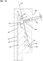
- FIGS. 11-19 illustrate alternate useful embodiments that can be used with the filter cartridge 24 and filter head 22 that provide a workable design leading to advantage.
- Advantages for each of these embodiments include those that improve the prior art such as having the ability to mount the filter cartridge 24 on the filter head 22 using torque smaller than the prior art, as well as, providing the seal with only a few revolutions and thereby avoiding the difficulty caused with possible cross-threading.
- the sleeve 84 is ribless. It differs from FIGS. 7 and 10 in that there is no rib 96 ( FIG. 7 ) projecting from the recess wall 102.
- the housing 28 is depicted as folded over the first end 91 of the sleeve 84 and has a projection 204 extending radially away from the recess wall 102. From a radially outwardly most point of the projection 204 of the housing 28, the housing 28 has a slope 206 that extends radially inwardly toward the recess wall 102 as it extends in a direction toward the base surface 110. The outwardly most point of projection 204 extends a distance X from the recess wall 102.
- the radial length 108 (in FIG. 7 ) and shown as Y is the distance from the recess wall 102 to the threaded section 106. Advantages are achieved when the distance X is less than or equal to 80% of the distance Y. Advantages include the ability to mount the filter cartridge 24 on the filter head 22 using torque smaller than the prior art, as well as, providing the seal with only a few revolutions and thereby avoiding the difficulty caused with possible cross-threading.
- the recess wall 102 includes a pocket 220 that extends beyond (below in the orientation of FIG. 12 ) the base surface 100.
- a horizontal line 224 that is the tangent line along a portion of the seal member 110 that is oriented adjacent, or against, the base surface 100. In the orientation of FIG. 12 , this is also the line 224 passing through (or tangent to) a lowest point of the seal member 110.
- a line 226 that is the tangent line along the most radially inwardly portion of the seal member 110. In many examples, the line 226 is about parallel to the recess wall 102. An intersection between line 224 and line 226 forms joint 222.
- the housing seal member 110 has a sealing compression region 114 (see FIG. 10 ), and the sealing compression region 114 in cross-section is defined by compression region line 116 ( FIG. 10 ). Advantages result when the line 118 ( FIG. 10 ), which is perpendicular to the compression region line 116, passes through the joint 222 and the housing seal member 110. Advantages include the ability to mount the filter cartridge 24 on the filter head 22 using torque smaller than the prior art, as well as, providing the seal with only a few revolutions and thereby avoiding the difficulty caused with possible cross-threading.
- the sleeve 84 has no recess wall 102.
- the seal holder recess 94 has a non-rectangular cross-section, which can be many shapes, including regular polygonal or irregular polygonal. In the example depicted in FIG. 13 , the seal holder recess 94 is triangular shaped having a radially inward most portion 240.
- the housing 28 is depicted as folded over the first end 91 of the sleeve 84 and has a projection 242 extending radially away from the inner portion 86 of the sleeve 84.
- the housing 28 From projection 242 of the housing 28, the housing 28 has a slope 246 that extends radially inwardly toward the recess 94 inward portion 240.
- the angle of the slope will be at least 2°, not greater than 60°, for example about 30-50°.
- Advantages include the ability to mount the filter cartridge 24 on the filter head 22 using torque smaller than the prior art, as well as, providing the seal with only a few revolutions and thereby avoiding the difficulty caused with possible cross-threading.
- the sleeve 84 has outwardly radially projecting rib 96 and is adjacent the first end 91 to forms ceiling 98 of the recess 94.
- adjacent the first end 91 it is meant that the rib 96 can be either be even with the first end 91or spaced from (either toward or away) a remaining portion of the sleeve 84 by a few mm, e.g., 5 mm or fewer.
- the rib 96 is adjacent the first end 91 by being spaced from the first end 91.
- Radially extending base surface 100 is opposite of the ceiling 98 forming a floor of the recess 94.
- the recess wall 102 extends axially between the ceiling 98 and the base surface 100.
- the base surface 100 has radial base length 104 extending from the recess wall 102.
- the housing 28 is folded over the first end 91 of the sleeve 84 and overlaps and forms part of the rib 96.
- the housing 28 also extends along and hugs the recess in the sleeve to form part of the ceiling 98 and recess wall 102. In this embodiment, the housing 28 extends to the base surface 100.
- the sleeve 84 is ribless. It differs from FIGS. 7 and 10 in that there is no rib 96 ( FIG. 7 ) projecting from the recess wall 102.
- the recess wall 102 has a ramp 250 extending radially inwardly as the ramp 250 extends from the first end 91 of the sleeve to the base surface 100.
- the ramp 250 is angled sufficiently to retain the seal member 110 in place and prevent it from rolling off the sleeve 84.
- Useful slope angles for the ramp 250 include at least 2°, not greater than 60°, for example about 3-10°.
- Housing 28 is depicted as folded over the first end 91 of the sleeve 84 and overlapping the ramp 250 to form housing ramp 252.
- the housing ramp 252 in this embodiment, is against the sleeve ramp 250 and can have about the same slope as the sleeve ramp 250 to extend radially inwardly as it extends from the first end 91 to the base surface 100.
- the sleeve 84 is ribless as the recess wall 102 extends straight between the first end 91 and the base surface 100.
- the housing 28 is depicted as folded over the first end 91 of the sleeve 84 and has a housing rib or projection 258 extending radially away from the recess wall 102.
- the housing rib or projection 258 extends radially outward to a bight section 260, which is the most radially outward point of the projection 258.
- the projection 258 forms a ceiling 262 to the seal holder recess 94.
- the housing extends along the recess wall 102 to the base surface 100.
- the outwardly most point of projection 258 extends a distance X from the recess wall 102.
- the radial length 108 (in FIG. 7 ) and shown as Y is the distance from the recess wall 102 to the threaded section 106. Advantages are achieved when the distance X is less than or equal to 80% of the distance Y.
- FIGS. 14-16 include the advantages illustrated in FIG. 10 . That is, the housing seal member 110 is held within the recess 94 and forms seal 172 with the filter head 22.
- the housing seal member 110 has sealing compression region 114, which is a portion of the housing sealing member 110 that receives the compressive force to form the seal 172 with the filter head 22.
- the sealing compression region 114 when viewed in cross-section, such as shown in FIG. 10 , is defined by a compression region line 116.
- the compression region line 116 is viewable in FIG. 10 and in FIG. 5 .
- a line 118 ( FIG. 10 ) perpendicular to the compression region line 116 passes through the joint 112 in the seal holder recess 94 and the seal member 110.
- line 224 that is the tangent line along a portion of the seal member 110 that is oriented adjacent, or against, the base surface 100. In these embodiments, this is also the line 224 passing through (or tangent to) a lowest point of the seal member 110.
- line 226 that is the tangent line along the most radially inwardly portion of the seal member 110. In many examples, the line 226 is about parallel to the recess wall 102, but note that line 226 is not parallel to recess wall 102 in FIG. 15 .
- An intersection between line 224 and line 226 forms joint 222.
- the housing seal member 110 has a sealing compression region 114 (see FIG.
- FIGS. 17-19 illustrate the use of housing seal members 110 that do not have a round cross-sectional shape. These embodiments provide workable designs leading to advantage. Advantages for each of these embodiments include those that improve the prior art such as having the ability to mount the filter cartridge 24 on the filter head 22 using torque smaller than the prior art, as well as, providing the seal with only a few revolutions and thereby avoiding the difficulty caused with possible cross-threading.
- the housing seal member 270 has a trapezoid-shaped cross-section with a straight top surface 272 (top surface being the one closest to the mouth 40, when oriented with the mouth 40 in the uppermost location) being shorter than a straight bottom surface 274.
- Sealing surface 276 is a straight surface angled downward and away from the top surface 272, as the sealing surface 276 extends from the top surface 272 to the bottom surface 274.
- the seal member 270 has a generally straight section 277 that is adjacent to the recess wall 102 and extends between the top surface 272 and bottom surface 274.
- the housing seal member 280 has a straight top surface 282 (top surface being the one closest to the mouth 40, when oriented with the mouth 40 in the uppermost location) being shorter than a straight bottom surface 284. Sealing surface 286 is angled downward and away from the top surface 282, as the sealing surface extends from the top surface 282 to the bottom surface 284. In this embodiment, the sealing surface 286 includes an outwardly radially projecting rib 288 extending therefrom.
- the seal member 280 has a pair of straight sections 287, 289 with a recess 285 therebetween that is adjacent to the recess wall 102 and extends between the top surface 282 and bottom surface 284.
- the housing seal member 290 has an X cross-sectional shape.
- the X shape includes portions 291, 293 that are oriented closest to or against the base surface 100.
- the X shape includes portions 295, 297 against the recess wall 102.
- line 226 that is the tangent line along the most radially inwardly portion of the seal member 270, 280, 290.
- the line 226 is about parallel to the recess wall 102.
- tangent in FIG. 17 , the section 277 adjacent to the recess wall 102 is a straight surface, so the line 226 tangent to the cross section line showing the section 277 is the line depicting the section 277 itself.
- the pair of sections 287, 289 adjacent to the recess wall 102 are straight, so the line 226 tangent to the cross sectional lines showing 287, 289 is depicting sections 287, 289 themselves.
- the tangent line 226 is a line that is tangent to each of portions 295, 297.
- the housing seal member 270, 280, 290 has a sealing compression region 114 (see FIG. 10 ), and the sealing compression region 114 in cross-section is defined by compression region line 116 ( FIG. 10 ).
- Advantages result when the line 118 ( FIG. 10 ), which is perpendicular to the compression region line 116, passes through the joint 222 and the housing seal member 110.
- Advantages include lower torque requirements to connect filter cartridge 24 on the filter head 22.
- One method is a method of installing filter cartridge 24 onto filter head 22.
- the method includes providing filter head 22 having an inlet arrangement 192, outlet arrangement 196, and outer wall 156 surrounding a cartridge-receiving interior 158.
- the outer wall 156 includes a rim 160 and threaded region 162 orientated toward the cartridge-receiving interior 158 adjacent the end rim 160.
- the method includes a step of providing the filter cartridge 24.
- the filter cartridge 24 includes housing 28, filter media construction 48 operably oriented in interior volume 38, and sleeve 84.
- the sleeve 84 surrounds and is against the housing 28.
- the sleeve 84 includes a threaded section 106 and defines seal holder recess 94. Seal member 110 is within the seal holder recess 94 and projects radially outwardly therefrom.
- the method includes a step of threadably mating the threaded section 106 of the sleeve 84 with the threaded region 162 of the filter head 22 to compress the seal member 110 and form an operable seal 172 between the filter head 22 and the filter cartridge 24.
- the seal 172 will be formed using a torque of less than 50% needed to form an operable seal using a comparable filter head that has a straight section instead of a ramp. In some examples, this torque is no greater than 10 N-m.
- operble seal it is meant a seal that can withstand pressures of about 100 psi.
- the step of threadably mating will include forming the seal 172 using a torque less than 55% needed to form an operable seal using a comparable filter head that has a straight section instead of a ramp.
- the step of threadably mating will including forming the seal 172 using a torque of less than 6 N-m and no greater than 8.2 N-m.
- the step of providing the filter head 22 includes providing the filter head outer wall 156 to have ramp 166.
- the threaded region 162 will be between the ramp 166 and the end rim 160.
- the step of threadably mating preferably includes compressing the ramp 166 against the seal member 110 to form the seal 172 between and against the ramp 166 and the sleeve 84.
- the step of providing the filter head 22 may include providing the filter head outer wall 156 to have the ramp 166 that in angled between 12 and 18 degrees from the outer wall 156 filter head 22.
- the method may further include a step of disconnecting the filter cartridge 24 and the filter head 22. This step will be after the step of threadably mating.
- the step of disconnecting the filter cartridge 24 from the filter head 22 will use a torque of less than 10 N-m.
- the step of disconnecting the filter cartridge 24 and the filter head 22 will use a torque of less than 7 N-m.
- the step of disconnecting the filter cartridge 24 and the filter head 22 will use a torque of less than 6.5 N-m and greater than 5 N-m.
- the step of providing a filter cartridge can include providing a filter cartridge 24 as variously characterized above, with certain features selected for advantage, but not necessarily requiring all features.
- the step of providing the filter head can include providing the filter head 22 as variously characterized above, with selective features for advantage, but not necessarily requiring all features.
- the usable materials for the filter housing 28 can include metals such as for example steel or aluminum.
- metals such as for example steel or aluminum.
- useable materials for the bowl can include plastics, metals, composites, or other materials capable of withstanding pressures typically experienced in filtration applications.
- Usable materials for the sleeve 84 can include plastic, metal, or other materials capable of withstanding the torque, pressures, and temperatures typically experienced in filtration applications.
- a filter cartridge comprises a housing; a filter media construction in the housing; and a sleeve on an outside of the housing; the sleeve being threaded and holding a housing seal member.
- the housing has a surrounding wall defining an interior volume, an open mouth in communication with the interior volume and a bottom opposite of the mouth; the surrounding wall having an interior surface in communication with the interior volume and an opposite exterior surface.
- the filter media construction is operably oriented in the interior volume of the housing.
- the sleeve is oriented against the exterior surface of the surrounding wall of the housing; the sleeve has an inner portion and an opposite exterior portion, the inner portion is oriented against the exterior surface of the surrounding wall.
- the sleeve includes opposite first and second ends, the first end being adjacent the open mouth of the housing.
- the sleeve has a seal holder recess along the exterior portion; and the housing seal member is operably held in the seal holder recess.
- the sleeve has a seal holder recess with a radially extending base surface.
- the sleeve has a seal holder recess with a recess wall.
- the sleeve has a seal holder recess with a radially extending base surface and a recess wall; the base surface having a radial base length extending from the recess wall.
- An outwardly radially projecting rib is adjacent to the first end of the sleeve forming a ceiling of the recess.
- the rib is part of the sleeve.
- the rib is part of the housing.
- the rib is even with the first end of the sleeve.
- the rib is spaced from the first end of the sleeve.
- the sleeve includes a plurality of threads projecting radially outwardly from a threaded section of the exterior portion of the sleeve.
- the sleeve includes a plurality of threads projecting radially outwardly from a threaded section of the exterior portion of the sleeve between the second end and the base surface, the threaded section having a radial length measured from the recess wall.
- the radial length of the threaded section is greater than the radial base length.
- the seal holder recess has a joint at an intersection between the base surface and the recess wall.
- the housing seal member has a sealing compression region; the sealing compression region in cross-section being defined by a compression region line.
- a line perpendicular to the compression region line passes through the joint in the seal holder recess and the housing seal member.
- the rib has a length less than 80% of the radial base length.
- the outwardly radially projecting rib has a length less than 60% of the radial base length.
- the outwardly radially projecting rib has a length less than 55% of the radial base length.
- the rib extends radially away from the recess wall a distance less than the base surface extends away from the recess wall.
- the base surface is located at least 4 mm and no greater than 15 mm from an axial rim defining the mouth of the housing.
- the base surface is located at least 7 mm and no greater than 11 mm from an axial rim defining the mouth of the housing.
- the sleeve includes a bevel surface between the base surface and the threaded section; the bevel surface being angled relative to the threaded section at an angle between 10-50°.
- the sleeve includes a bevel surface between the base surface and the threaded section; the bevel surface being angled relative to the threaded section at an angle between 12-30°.
- the sleeve includes a bevel surface between the base surface and the threaded section; the bevel surface being angled relative to the threaded section at an angle between 13-17°.
- the bevel surface has an axial length between the base surface and the threaded section of 0.7-2 mm.
- the bevel surface has an axial length between the base surface and the threaded section of 0.8-1.5 mm.
- the sleeve includes a radially extending stop member between the threaded section and the second end.
- the stop member is located at least 17 mm and no greater than 30 mm from an axial rim defining the mouth of the housing.
- the stop member is located at least 18 mm and no greater than 28 mm from an axial rim defining the mouth of the housing.
- the stop member projects radially outwardly a distance greater than any other portion of the sleeve.
- the filter media construction comprises a cylinder of pleated filter media secured between first and second end caps.
- a ring projects axially from the first end cap in a direction away from a remaining part of the filter media construction; and a first end cap seal member is held by the ring.
- the first end cap seal member projects radially outwardly from the ring.
- the filter media construction is fixed and non-removably mounted in the interior volume of the housing.
- the housing bottom includes a drain valve.
- the housing seal member projects radially outwardly farther than the rib.
- the wall of the housing overlaps the first end of the sleeve.
- the wall of the housing overlaps the projecting rib and is in extension along the exterior portion of the sleeve along the recess wall.
- a filter head removably attached to the filter cartridge.
- the filter head includes an outer wall surrounding a cartridge-receiving interior; the outer wall having an end rim, a threaded region oriented toward the cartridge-receiving interior adjacent to the end rim, and a ramp; the ramp being angled in a direction toward the cartridge-receiving interior and positioned to engage the housing seal member to form a seal with the filter cartridge when the filter head and filter cartridge are operably attached to each other.
- the threaded region is in between the ramp and the end rim.
- An operable section of the ramp is angled between 5 and 45 degrees from the outer wall of the filter head.
- An operable section of the ramp is angled between 10 and 30 degrees from the outer wall of the filter head.
- An operable section of the ramp is angled between 12 and 18 degrees from the outer wall of the filter head.
- the filter head includes an inlet arrangement for conveying unfiltered fluid to the filter cartridge and an outlet arrangement for conveying filtered fluid from the filter cartridge.
- a filter assembly includes a filter head having a ramp; a filter cartridge removably attached to the filter head; the filter cartridge having a seal member; and wherein the ramp on the filter head is compressed against the seal member to form a seal between the filter head and the filter cartridge.
- the filter head includes an inlet arrangement, an outlet arrangement, and an outer wall surrounding a cartridge-receiving interior; the outer wall having an end rim, a threaded region oriented toward the cartridge-receiving interior adjacent to the end rim.
- the filter cartridge includes a housing, a filter media construction operably oriented in an interior volume of the housing, and a sleeve surrounding and against the housing.
- the sleeve includes a threaded section mateably engaging the threaded region of the filter head, a seal holder recess, and the seal member being within the seal holder recess and projecting radially outwardly.
- An operable section of the ramp is angled between 5 and 45 degrees from the outer wall of the filter head.
- An operable section of the ramp is angled between 10 and 30 degrees from the outer wall of the filter head.
- An operable section of the ramp is angled between 12 and 18 degrees from the outer wall of the filter head.
- the sleeve has an inner portion and an opposite exterior portion, the inner portion being oriented against an exterior surface of the housing; the sleeve including opposite first and second ends, the first end being adjacent an open mouth of the housing; wherein, the seal holder recess is along the exterior portion, the recess being defined by an outwardly radially projecting rib adjacent to the first end forming a ceiling, a radially extending base surface opposite of the ceiling, and a recess wall extending axially between the ceiling and the base surface; the seal holder recess has a joint being defined at an intersection between a line tangent to a lowest point of the seal member, when the cartridge is oriented with the mouth as uppermost, and a line tangent to a most radially inward portion of the seal member; and the ramp compressing against the housing seal member in cross-section along a compression region line; a line perpendicular to the compression region line passes through the joint in the seal holder recess and the housing seal member.
- the sleeve includes a bevel surface between the base surface and the threaded section; the bevel surface being angled relative to the threaded section at an angle between 10-50°.
- the sleeve includes a bevel surface between the base surface and the threaded section; the bevel surface being angled relative to the threaded section at an angle between 12-30°.
- the sleeve includes a bevel surface between the base surface and the threaded section; the bevel surface being angled relative to the threaded section at an angle between 13-17°.
- the bevel surface has an axial length between the base surface and the threaded section of 0.7-2 mm.
- the bevel surface has an axial length between the base surface and the threaded section of 0.8-1.5 mm.
- the sleeve includes a radially extending stop member between the threaded section and the second end.
- the stop member is located at least 17 mm and no greater than 30 mm from an axial rim defining a mouth of the housing.
- the stop member is located at least 18 mm and no greater than 28 mm from an axial rim defining a mouth of the housing.
- the stop member projects radially outwardly a distance greater than any other portion of the sleeve.
- the filter media construction comprises a cylinder of pleated filter media secured between first and second end caps.
- a ring projects axially from the first end cap in a direction away from a remaining part of the filter media construction; and a first end cap seal member is held by the ring.
- the first end cap seal member projects radially outwardly from the ring.
- the filter media construction is fixed and non-removably mounted in the interior volume of the housing.
- the filter cartridge further includes a drain valve.
- a method of installing a filter cartridge on a filter head comprising providing a filter head; providing a filter cartridge with a sleeve and a seal member; threadably mating a threaded section of the sleeve with a threaded region of the filter head to compress the seal member and form a seal between the filter head and the filter cartridge, the seal being formed using a torque less than 50% needed to form an operable seal using a comparable filter head that has a straight section instead of a ramp.
- the step of providing a filter head includes providing a head having an inlet arrangement, an outlet arrangement, and an outer wall surrounding a cartridge-receiving interior; the outer wall having an end rim, and a threaded region oriented toward the cartridge-receiving interior adjacent to the end rim.
- the step of providing a filter cartridge includes providing a housing, a filter media construction operably oriented in an interior volume of the housing, and a sleeve surrounding and against the housing; the sleeve having a threaded section; the sleeve defining a seal holder recess; the seal member being within the seal holder recess and projecting radially outwardly.
- the step of threadably mating includes forming the seal using a torque less than 55% needed to form an operable seal using a comparable filter head that has a straight section instead of a ramp.
- the step of threadably mating includes forming the seal using a torque of no greater than 10 N-m.
- the step of providing a filter head includes providing the filter head outer wall to having a ramp, the threaded region being between the ramp and the end rim; and the step of threadably mating includes compressing the ramp against the seal member to form the seal between and against the ramp and the sleeve.
- the step of providing a filter head includes providing the filter head outer wall to having the ramp that is angled between 12 and 18 degrees from the outer wall of the filter head.
- the present disclosure comprises for instance the following:
Abstract
Description
- This application is being filed on February 20, 2017, as a PCT International Patent application and claims the benefit of priority to
U.S. Provisional patent application Serial No. 62/302,553, filed March 2, 2016 U.S. Provisional patent application Serial No. 62/352,609, filed June 21, 2016 - This disclosure relates to filter cartridges, filter assemblies including the cartridge connected to a filter head, and methods of use. The filter arrangement in this disclosure can be used for filtration of fluids, such as liquids, especially fuel, hydraulics, and lube.
- Filters are commonly used in connection with lubrication systems and fuel systems for internal combustion engines and hydraulic systems for heavy duty equipment. Filters are also used in many other types of liquid systems. In these types of systems, the filter is changed periodically. One type of typical filter system used is a spin-on canister filter.
- Spin-on canister filters are disposable units, which typically include a single-use housing holding a permanently mounted, non-replaceable filter element (cartridge filter). The canister holding the cartridge filter is usually spun onto a filter head by a threaded engagement. The liquid to be cleaned passes from the filter head and into the housing for filtering. The cleaned liquid exits the housing and reenters the filter head. After some period of use, the spin-on canister filter is removed from the filter head and is discarded. A new spin-on canister filter is then mounted onto the filter head.
- Typically, there is some type of seal arrangement between the filter and the filter head. In the past, the seal arrangement could put a drag when installing and removing, which causes difficulty in maintenance. Further, in prior art designs, it takes several revolutions of the housing onto the filter head before the threads bottom out. This can cause difficulty with cross-threading or not properly mounting the filter onto the filter head. Improvements are desirable.
- A filter cartridge and filter assembly are provided to improve the problems of the prior art.
- In a first aspect, a filter cartridge is provided including a housing, a filter media construction, a sleeve, and a housing seal member.
- The housing has a surrounding wall defining an interior volume. The housing has an open mouth in communication with the interior volume and a bottom opposite of the mouth. The surrounding wall has an interior surface in communication with the interior volume and an opposite exterior surface.
- The filter media construction is operably oriented in the interior volume of the housing. The sleeve is oriented against the exterior surface of the surrounding wall. The sleeve has an inner portion and an opposite exterior portion. The inner portion is oriented against the exterior surface of the surrounding wall. The sleeve includes opposite first and second ends, with the first end being adjacent to the open mouth of the housing. The sleeve includes a seal holder recess along the exterior portion. A radially extending base surface is part of the recess. A recess wall extends axially at least partially between the base surface and the first end of the sleeve. The base surface has a radial base length extending from the recess wall. The sleeve includes a plurality of threads projecting radially outwardly from a threaded section of the exterior portion of the sleeve between the second end and the base surface. The threaded section has a radial length measured from the recess wall, wherein the radial length of the threaded section is greater than the radial base length. The housing seal member is operably held in the seal holder recess.
- Independent of the above, and in another aspect, a filter cartridge is provided. The filter cartridge includes a housing, a filter media construction, a sleeve, and a housing seal member. The housing has a surrounding wall defining an interior volume. The housing has an open mouth in communication with the interior volume and a bottom opposite of the mouth. The surrounding wall has an interior surface in communication with the interior volume and an opposite exterior surface. The filter media construction is operably oriented in the interior volume of the housing. The sleeve is against the exterior surface of the surrounding wall. The sleeve has an inner portion and an opposite exterior portion, with the inner portion being oriented against the exterior surface of the surrounding wall. The sleeve includes opposite first and second ends, the first end being adjacent the open mouth of the housing. The sleeve includes a seal holder recess along the exterior portion. The recess includes a radially extending base surface and a recess wall extending axially at least partially between the base surface and the first end of the sleeve. The seal holder recess has a joint at an intersection between the base surface and the recess wall. The sleeve includes a threaded section in the exterior portion of the sleeve between the second end and the base surface. The housing seal member is operably held in the seal holder recess. The housing seal member has a sealing compression region. The sealing compression region in cross-section is defined by a compression region line. A line perpendicular to the compression region line passes through the joint in the seal holder recess and the seal member.
- Independent of the above, a filter cartridge is provided comprising a housing having a surrounding wall defining an interior volume; the housing having an open mouth in communication with the interior volume and a bottom opposite of the mouth; the surrounding wall having an interior surface in communication with the interior volume and an opposite exterior surface. A filter media construction is operably oriented in the interior volume of the housing; and a sleeve is against the exterior surface of the surrounding wall. The sleeve has an inner portion and an opposite exterior portion. The inner portion is oriented against the exterior surface of the surrounding wall. The sleeve includes, opposite first and second ends, with the first end being adjacent the open mouth of the housing; a seal holder recess along the exterior portion and a housing seal member being held in the seal holder recess; a joint being defined at an intersection between a line tangent to a lowest point of the seal member, when the cartridge is oriented with the mouth as uppermost, and a line tangent to a most radially inward portion of the seal member; a threaded section in the exterior portion of the sleeve between the second end and the base surface. The housing seal member has a sealing compression region; the sealing compression region in cross-section is defined by a compression region line. A line perpendicular to the compression region line passes through the joint and the housing seal member.
- Independent of the above, the seal holder recess may be defined by an outwardly radially projecting rib adjacent to the first end of the sleeve forming a ceiling of the recess, wherein the seal holder recess includes radially extending base surface and a recess wall extending axially between the base surface and the ceiling.
- In aspects that include a rib, the rib can be even with the first end of the sleeve.
- In aspects that include a rib, the rib can be spaced from the first end of the sleeve.
- In aspects that include a rib, the rib can be part of the sleeve.
- In aspects that include a rib, the rib can be part of the housing.
- In aspects that include a rib, the rib can be part of both the sleeve and the housing.
- In aspects that include a rib, the outwardly radially projecting rib can have a length less than 80% of the radial base length.
- In aspects that include a rib, the outwardly radially projecting rib can have a length less than 60% of the radial base length.
- In aspects that include a rib, the outwardly radially projecting rib can have a length less than 55% of the radial base length.
- The rib can extend radially away from the recess wall a distance less than the base surface extends away from the recess wall.
- The base surface is located at least 4 mm and no greater than 15 mm from an axial rim defining the mouth of the housing.
- The base surface can be located at least 7 mm and no greater than 11 mm from an axial rim defining the mouth of the housing.
- The sleeve can include a bevel surface between the base surface and the threaded section, the bevel surface being angled relative to the threaded section at an angle between 10-50 degrees.
- The sleeve can include a bevel surface between the base surface and the threaded section, with the bevel surface being angled relative to the threaded section at an angle between 12-30 degrees.
- The sleeve can include a bevel surface between the base surface and the threaded section, the bevel section being angled relative to the threaded section at an angle between 13-17 degrees.
- The bevel surface can have an axial length between the base surface and the threaded section of 0.7-2 mm.
- The bevel surface can have an axial length between the base surface and the threaded section of 0.8-1.5 mm.
- The sleeve can include a radially extending stop member between the threaded section and the second end.
- The stop member is located at least 17 mm and no greater than 30 mm from an axial rim defining the mouth of the housing.
- The stop member is located at least 18 mm and no greater than 28 mm from an axial rim defining the mouth of the housing.
- The stop member projects radially outwardly a distance greater than any other portion of the sleeve.
- The filter media construction comprises a cylinder of pleated filter media secured between first and second end caps.
- A ring may project axially from the first end cap in a direction away from a remaining part of the filter media construction, and the first end cap seal member can be held by the ring.
- The first end cap seal member may project radially outwardly from the ring.
- The filter media construction may be fixed and non-removably mounted in the interior volume of the housing.
- The housing bottom can include a drain valve.
- The housing seal member may project radially outwardly farther than the rib.
- The wall of the housing may overlap the first end of the sleeve.
- The wall of the housing may overlap the projecting rib and be in extension along the exterior portion of the sleeve along the recess wall.
- In another aspect, a filter assembly is provided including a filter cartridge as variously characterized above and further including a filter head removably attached to the filter cartridge.
- The filter head can include an outer wall surrounding a cartridge-receiving interior. The outer wall has an end rim, a threaded region oriented toward the cartridge-receiving interior adjacent to the end rim, and a ramp. The ramp may be angled in a direction toward the cartridge receiving interior and positioned to engage the housing seal member to form a seal with the filter cartridge when the filter head and filter cartridge are operably attached to each other.
- The threaded region can be between the ramp and the end rim.
- The ramp can be angled between 5 and 45 degrees from the outer wall of the filter head.
- The ramp can be angled between 10 and 30 degrees from the outer wall of the filter head.
- The ramp can be angled between 12 and 18 degrees from the outer wall of the filter head.
- The filter head may include an inlet arrangement for conveying unfiltered fluid to the filter cartridge in an outlet arrangement for conveying filtered fluid from the filter cartridge.
- Independent of the above, in another aspect, a filter assembly is provided. The filter assembly includes a filter head having an inlet arrangement, an outlet arrangement, and an outer wall surrounding a cartridge-receiving interior. The outer wall has an end rim, a threaded region oriented toward the cartridge-receiving interior adjacent to the end rim, and a ramp. A filter cartridge is removably attached to the filter head. The filter cartridge includes a housing, a filter media construction operably oriented in an interior volume of the housing, and a sleeve surrounding and against the housing. The sleeve has a threaded section mateably engaging the threaded region of the filter head. The sleeve defines a seal holder recess. A seal member is within the seal holder recess and projects radially outwardly. The ramp on the filter head is compressed against the seal member to form a seal between the filter head and the filter cartridge.
- The ramp can be angled between 5 and 45 degrees from the outer wall of the filter head.
- The ramp can be angled between 10 and 30 degrees from the outer wall of the filter head.
- The ramp can be angled between 12 and 18 degrees from the outer wall of the filter head.
- The sleeve has an inner portion and an opposite exterior portion. The inner portion can be oriented against the exterior surface of the housing. The sleeve includes opposite first and second ends, with the first end being adjacent an open mouth of the housing. The seal holder recess is along the exterior portion, the recess including a radially extending base surface and a recess wall extending axially at least partially between the base surface and the first end of the sleeve. The seal holder recess has a joint being defined at an intersection between a line tangent to a lowest point of the seal member, when the cartridge is oriented with the mouth as uppermost, and a line tangent to a most radially inward portion of the seal member. The threaded section of the sleeve is in the exterior portion of the sleeve between the second end and the base surface. The ramp compresses against the housing seal member in cross-section along a compression region line. A line perpendicular to the compression region line passes through the joint in the seal holder recess and the seal member.
- The sleeve may include a bevel surface between the base surface and the threaded section. The bevel section can be angled relative to the threaded section at an angle between 10-50 degrees.
- The sleeve can include a bevel surface between the base surface and the threaded section, with the bevel surface being angled relative to the threaded section at an angle between 12-30 degrees.
- The sleeve can include a bevel surface between the base surface and the threaded section, with the bevel surface being angled relative to the threaded section at an angle between 13-17 degrees.
- The bevel surface has an axial length between the base surface and the threaded section of 0.7-2 mm.
- The bevel section can have an axial length between the base surface and the threaded section of 0.8-1.5 mm.
- The sleeve can include a radially extending stop member between the threaded section and the second end.
- The stop member can be located at least 17 mm and no greater than 30 mm from an axial rim defining a mouth of the housing.
- The stop member can be located at least 18 mm and no greater than 28 mm from an axial rim defining a mouth of the housing.
- The stop member may project radially outwardly a distance greater than any other portion of the sleeve.
- The filter media construction may comprise a cylinder of pleated filter media secured between first and second end caps.
- A ring can project from the first end cap in a direction away from a remaining part of the filter media construction, and a first end cap seal member can be held by the ring.
- The first end cap seal member may project radially outwardly from the ring.
- The filter media construction is fixed and non-removably mounted in the interior volume of the housing.
- The filter cartridge may further include a drain valve.
- Independent of the above, and another aspect, a method of installing a filter cartridge on a filter head is provided. The method includes steps of providing a filter head, providing a filter cartridge, and threadably mating the filter head and filter cartridge. The step of providing a filter head includes a providing a head having an inlet arrangement, and outlet arrangement, and an outer wall surrounding a cartridge-receiving interior. The outer wall has an end rim and a threaded region oriented toward the cartridge-receiving interior adjacent to the end rim. The step of providing a filter cartridge includes providing a housing, a filter media construction operably oriented in an interior volume of the housing, and a sleeve surrounding and against the housing. The sleeve has a threaded section, defines a seal holder recess, and a seal member that is within the seal holder recess and projecting radially outwardly. The step of threadably mating includes mating the threaded section of the sleeve with the threaded region of the filter head to compress the seal member and form a seal between the filter head and the filter cartridge, the seal being formed using a torque less than 50% needed to form an operable seal using a comparable filter head that has a straight section instead of a ramp.
- The step of threadably mating may include forming the seal using a torque less than 55% needed to form an operable seal using a comparable filter head that has a straight section instead of a ramp.
- The step of threadably mating may include forming the seal using a torque of no greater than 15 N-m.
- The step of providing a filter head may include providing the filter head outer wall to have a ramp, wherein the threaded region is between the ramp and the end rim. The step of threadably mating may include compressing the ramp against the seal member to form the seal between and against the ramp and the sleeve.
- The step of providing a filter head may include providing the filter head outer wall to have the ramp be angled between 12 and 18 degrees from the outer wall of the filter head.
- After the step of threadably mating, there can be a step of disconnecting the filter cartridge and filter head by using a torque of less than 50% needed to disconnect using a comparable filter head that has a straight section instead of a ramp.
- After the step of threadably mating, there can be a step of disconnecting the filter cartridge and filter head by using a torque of less than 65% needed to disconnect using a comparable filter head that has a straight section instead of a ramp.
- After the step of threadably mating, there can be a step of disconnecting the filter cartridge and filter head by using a torque of less than 15 N-m.
- The step of providing a filter cartridge can include providing a filter cartridge as variously characterized in any of the above characterizations.
- The step of providing a filter head can include providing a filter head according to the various characterizations above.
- It is noted that not all of the specific features described herein need to be incorporated in an arrangement for the arrangement to have some selected advantage according to the present disclosure.
-
-
FIG. 1 is an exploded, top perspective view of a filter assembly constructed in accordance with the principles of this disclosure; -
FIG. 2 is an exploded, bottom perspective view of the filter assembly ofFIG. 1 ; -
FIG. 3 is a top view of the assembled filter assembly ofFIGS. 1 and2 ; -
FIG. 4 is a cross-sectional view of the filter assembly ofFIG. 3 , the cross-section being taken along the line 4-4 ofFIG. 3 ; -
FIG. 5 is a cross-sectional view of the filter cartridge used in the filter assembly ofFIGS. 3 and4 ; -
FIG. 6 is a cross-sectional view of the sleeve used with the filter cartridge ofFIG. 5 ; -
FIG. 7 is an enlarged, cross-sectional view of Section A ofFIG. 6 ; -
FIG. 8 is a cross-sectional view of the filter head shown as part of the filter assembly ofFIG. 4 ; -
FIG. 9 is an enlarged view of Section B-B ofFIG. 8 ; -
FIG. 10 is an enlarged view of Section C-C ofFIG. 4 ; -
FIG. 11 is an enlarged cross-sectional view, similar toFIG. 10 , but without the filter head shown and depicting another embodiment; -
FIG. 12 is an enlarged cross-sectional view, similar toFIG. 10 , but without the filter head shown and depicting another embodiment; -
FIG. 13 is an enlarged cross-sectional view, similar toFIG. 10 , but without the filter head shown and depicting another embodiment; -
FIG. 14 is an enlarged cross-sectional view, similar toFIG. 10 , but without the filter head shown and depicting another embodiment; -
FIG. 15 is an enlarged cross-sectional view, similar toFIG. 10 , but without the filter head shown and depicting another embodiment; -
FIG. 16 is an enlarged cross-sectional view, similar toFIG. 10 , but without the filter head shown and depicting another embodiment; -
FIG. 17 is an enlarged cross-sectional view, similar toFIG. 10 , but without the filter head shown and depicting another embodiment; -
FIG. 18 is an enlarged cross-sectional view, similar toFIG. 10 , but without the filter head shown and depicting another embodiment; and -
FIG. 19 is an enlarged cross-sectional view, similar toFIG. 10 , but without the filter head shown and depicting another embodiment. - A filter cartridge and a filter assembly that improve the problems of the prior art is shown in
FIGS. 1-4 . - The filter assembly constructed in accordance with the principles of this disclosure is illustrated in exploded perspective view in
FIGS. 1 and2 at 20. Thefilter assembly 20 includes afilter head 22. Thefilter head 22 will be mounted or connected to a system, such as equipment with a lubrication system or fuel system for internal combustion engines, or a hydraulic system for heavy duty equipment. Thefilter head 22 will be in liquid communication with components of this equipment such that the liquid to be filtered will flow into thefilter head 22 for filtering by thefilter assembly 20 and then exit thefilter head 22 in a filtered state for use by the equipment. - The
filter assembly 20 further includes afilter cartridge 24. Thefilter cartridge 24, in this embodiment, is a spin-oncanister filter 26. The spin-oncanister filter 26 has a single use can orhousing 28 holding a permanently mounted,non-replaceable filter element 30. Thehousing 28 holding thefilter element 30 is spun onto thefilter head 22 by a threaded engagement. As can be seen in Fig. 22, thefilter head 22 hasthreads 32, and thehousing 28 hasthreads 34. The liquid to be cleaned passes from thefilter head 22 and into thehousing 28 for filtering. The liquid flows through thefilter element 30 for filtering, reenters thefilter head 22, and then exits thefilter head 22 to be used by downstream equipment. After some period of use, thefilter cartridge 24 is removed from thefilter head 22 and is discarded. Anew filter cartridge 24 may then be provided and mounted onto thefilter head 22 for filtering. In alternate embodiments, thefilter assembly 20 could be a bowl-cartridge filter, in which the housing forms a reusable bowl that connects to the filter head, and a replaceable filter cartridge is held within the bowl. - Attention is directed to
FIG. 5. FIG. 5 is a cross-sectional view offilter cartridge 24. As mentioned previously, thefilter cartridge 24 includes thehousing 28 holding thenon-removable filter element 30. - The
filter housing 28 includes a surroundingwall 36. Thehousing wall 36 will typically be a thin-walled construction of metal. The surroundingwall 36 of thehousing 28 defines aninterior volume 38. Thehousing 28 has anopen mouth 40. Theopen mouth 40 is in communication with theinterior volume 38. - The
housing 28 includes ahousing bottom 42. The bottom 42 is at an end of thehousing 28 opposite of themouth 40. The surroundingwall 36 has aninterior surface 44. Theinterior surface 44 is in communication with theinterior volume 38. On an opposite side of thewall 36 from theinterior surface 44 is anexterior surface 46. A central,longitudinal axis 55 passes through thecartridge 24 as it extends through theopen mouth 40 andhousing bottom 42. - The
filter element 30 is permanently and non-removably mounted in theinterior volume 38 of thehousing 28. Thefilter element 30 includes afilter media construction 48. Thefilter media construction 48 is operably orientated in theinterior volume 38 of thehousing 28. Thefilter media construction 48 may be embodied in many different forms. In many embodiments, thefilter media construction 48 includes pleatedmedia 50. Thepleated media 50 may be cellulose, glass, synthetic, or a blend of any of these. Thefilter media construction 48 may include fine fiber. - In many embodiments, the
filter media construction 48 is generally tubular, which can include oval or cylindrical in shape. In this embodiment, it is cylindrical in shape such that thepleated media 50 defines anopen filter interior 52. Thefilter media construction 48, including if it is pleatedmedia 50, may be supported by an inner support, such as a perforatedinner liner 54. Theinner liner 54 supports the pleats and prevents the pleats in thepleated media 50 from collapsing. - The
filter media construction 48 has opposite ends 56, which is adjacent theopen mouth media construction 48 at theend 56 is afirst end cap 60. Thefirst end cap 60 is an open end cap because it has anopening 62 in its center that is in communication with theopen filter interior 52. Thefirst end cap 60 can be made from various types of material, including non-metal, such as nylon or hard plastic. Thefirst end cap 60 is secured to thefilter media construction 48 by either molding thefirst end cap 60 directly to thefilter media construction 48 or by other methods such as adhesive or potting material. - A
second end cap 64 is secured to theend 58 of thefilter media construction 48. Thesecond end cap 64 will typically be made of the same materials as thefirst end cap 60, which can be nylon or hard plastic. Thesecond end cap 64 may be closed to the open filter interior 52, but in some embodiments, it can be selectively opened by use of a drain valve, not shown inFIG. 5 . A mountingarrangement 66 for the drain valve can been seen inFIG. 5 as part of thesecond end cap 64. Thehousing 28 can be opened at access opening 68, which may then allow the drain valve to drain fluid from thefilter cartridge 24. - Referring again to the
first end cap 60, there is aring 70 that projects axially from thefirst end cap 60 in a direction away from thesecond cap 64 and away from a remaining part of thefilter media construction 48. Thering 70, in this embodiment, is adjacent to theopening 62 of thefirst end cap 60. Thering 70 defines agroove 72. Thegroove 72 opens in a radially outward direction, toward theinterior surface 44 of the surroundingwall 36. Located within thegroove 72 is first endcap seal member 74. The firstend cap seal 74 may be embodied as an O-ring. The first endcap seal member 74 is oriented in a direction radially outwardly from thering 70 and toward theinterior surface 44 of the surroundingwall 36. It forms aseal 165 with thefilter head 22, as described further below in connection withFIGS. 8 and4 . - While many embodiments are possible, in this embodiment, the
first end cap 60 includes an optional centeringarrangement 76. Thecenter arrangement 76 includes a pair ofaxial projections first end cap 60 in a direction away from thesecond end cap 64 and a remaining portion of thefilter media construction 48. Thecenter arrangement 76 helps to guide and mount thefilter cartridge 24 to thefilter head 22. Theaxial projections ring 70 and are located adjacent to outerradial edge 80 of thefirst end cap 60. - The
first end cap 60 further includes a plurality of outer radial projections 82 (FIGS. 1 and5 ). The outerradial projections 82 help to center thefilter media construction 48 within thehousing 28 by pressing radially against theinterior surface 44 of thehousing wall 46. - The
filter cartridge 24 further includes asleeve 84. Thesleeve 84 will be secured to thehousing 28 along theexterior surface 46 of thehousing 28. In many embodiments, thesleeve 84 is mounted against theexterior surface 46 of the surroundingwall 36. - An enlarged view of the
sleeve 84 is illustrated in detail inFIG. 6 . Thesleeve 84 has aninner portion 86 and anopposite exterior portion 88. Theinner portion 86, in the embodiment shown, is orientated against theexterior surface 46 of the surroundingwall 36. - The
sleeve 84 can be made from many different types of materials, including metal or non-metal. In preferred embodiments, the sleeve is made from non-metal, such as plastic, for example, nylon. - In reference to
FIG. 6 , thesleeve 84 has opposite first and second ends 91, 92. Thefirst end 91 is adjacent the open mouth 40 (FIG. 5 ) of thehousing 28. Thesecond end 92 is located spaced from theopen mouth 40 and typically in the upper one-third of thehousing 28, when theopen mouth 40 is orientated to be at the top. - The
sleeve 84 includes aseal holder recess 94. Theseal holder recess 94 is along theexterior portion 88. -
FIG. 7 shows an enlarged view of one cross-sectional view portion of thesleeve 84, the section shown at Section A inFIG. 6 . Thesleeve 84 has an outwardly radially projectingrib 96. Therib 96 is adjacent thefirst end 91 and forms aceiling 98 of therecess 94. By "adjacent thefirst end 91" it is meant that therib 96 can be either be even with the first end 91or spaced from (either toward or away) a remaining portion of thesleeve 84 by a few mm, e.g., 5 mm or fewer. InFIG. 7 , therib 96 is even with thefirst end 91. SeeFIG. 14 for one example embodiment (of many possibilities) in which therib 96 is adjacent thefirst end 91 by being spaced from thefirst end 91. A radially extendingbase surface 100 is opposite of theceiling 98 forming a floor of therecess 94. Arecess wall 102 extends axially between theceiling 98 and thebase surface 100. Thebase surface 100 has aradial base length 104 extending from therecess wall 102. Advantages including sealing at a lower torque are achieved when therib 96 extends a radial distance fromrecess wall 102 less than thebase surface 100 extends away from therecess wall 102. - The
housing threads 34 project radially outwardly from threadedsection 106 of theexterior portion 88 of thesleeve 84 between thesecond end 92 and thebase surface 100. The threadedsection 106 has aradial length 108 measured from therecess wall 102 to theexterior portion 88 from where theindividual threads 34 start to project from theexterior portion 88. Theradial length 108 of the threadedsection 106 is greater than theradial base length 104. This arrangement helps to contribute to afilter cartridge 24 that is easier to mount to thefilter head 22 than prior art arrangements, requiring much less torque. - In reference to
FIGS. 4 and10 , ahousing seal member 110 is operably held in theseal holder recess 94. Thehousing seal member 110 forms a radially outwardly directedseal 172 with thefilter head 22, when thefilter cartridge 24 is operably connected to thefilter head 22. As will be explained below, thehousing wall 36 can optionally include a section 37 (FIG. 10 ) that extends into and line at least a portion of therecess 94, such that theseal 172 is formed between and against thefilter head 22, thesleeve 84, and thesection 37 of thehousing wall 36 extending into therecess 94. - Again in reference to
FIG. 7 , theseal holder recess 94 includes a joint 112 at an intersection between thebase surface 100 and therecess 102. The joint 112 need not be a 90 degree corner, but can be on a radius. For example, the joint 112 can be on a radius 0.25 inches. Many embodiments are possible. The radius can be larger or smaller, and the angle between thebase surface 100 andrecess 102 can be larger or smaller. - As mentioned previously, there is a
housing seal member 110 that is operably held in theseal holder recess 94. Attention is directed toFIG. 10 which shows thehousing seal member 110 held within therecess 94 and formingseal 172 with thefilter head 22. As can be appreciated from the drawings shown inFIG. 10 , thehousing seal member 110 has sealingcompression region 114, which is a portion of thehousing sealing member 110 that receives the compressive force to form theseal 172 with thefilter head 22. In this embodiment, the sealingcompression region 114, when viewed in cross-section, such as shown inFIG. 10 , is defined by acompression region line 116. Thecompression region line 116 is viewable inFIG. 10 and inFIG. 5 . A line 118 (FIG. 10 ) perpendicular to thecompression region line 116 passes through the joint 112 in theseal holder recess 94 and the sealingmember 110. In this embodiment, "passing through the sealingmember 110" means extending through more than one point of the sealingmember 110; that is, if theline 118 is only tangent (a line that touches a curved surface but does not intersect it) to the sealingmember 110, it would not pass through the sealingmember 110 according to this definition. In general, in this example, theline 118 will not be perpendicular to the central axis 55 (FIG. 5 ), and theline 116 will not be parallel to thecentral axis 55. - The arrangement is formed to achieve advantages, including a torque that is less than needed in the prior art to reliably secure the
filter cartridge 24 to thefilter head 22. Some preferred arrangements are described herein that lead to this result. For example, inFIG. 7 , the outwardly radially projectingrib 96 has a radially projecting length that is less than 80% of the length of theradial base line 104. The many embodiments, the length of therib 96 is less than 60% of theradial base length 104. In even more preferred embodiments, therib 96 has a length of less than 55 percent of theradial base length 104. - Further arrangements that lead to advantage include the
base surface 100 being located at 4 mm and no greater than 15 mm from an axial rim 120 (FIG. 5 ) defining themouth 40 of thehousing 28. In more preferred embodiments, thebase surface 100 is located at least 7 mm and no greater than 11 mm, preferably about 9 mm, from theaxial rim 120 of themouth 40 of thehousing 28. - Other arrangements that lead to advantage include the
sleeve 84 having a beveled surface 122 (FIG. 7 ). Thebeveled surface 122 is between thebase surface 100 and the threadedsection 106. Advantages result by having thebeveled surface 122 being angled relative to the threadedsection 106 at anangle 124 between 13-17 degrees. - The
beveled surface 122 can have anaxial length 126 between thebase surface 100 and the threadedsection 106 of 0.7-2 mm. In more preferred embodiments, thebeveled surface 122 can have theaxial length 126 between thebase surface 100 and the threadedsection 106 of 0.8-1.5 mm. - In
FIG. 7 , it can be seen how in the particular embodiment illustrated, thesleeve 84 includes a radially extendingstop member 128. Thestop 128 is between the threadedsection 106 and thesecond end 92 of thesleeve 84. Thestop member 128 can be located at least 17 mm and no greater than 30 mm from the axial rim 120 (FIG. 5 ) defining themouth 40 of thehousing 28. In embodiments that lead to more preferred advantages, thestop member 128 is located at least 18 mm and no greater than 28 mm, preferably about 26 mm, from theaxial rim 120 defining themouth 40 of thehousing 28. In still further arrangements leading to advantages, thestop member 128 projects radially outwardly a distance that is greater than any other portion of thesleeve 84. This can be seen in the particular arrangement shown inFIG. 7 . - In reference again to
FIG. 5 , thehousing seal member 110 projects radially outwardly further than therib 96. This can lead to advantage of forming a seal with a filter head with less torque than prior art arrangements. - In reference now to
FIGS. 5 and10 , in many preferred arrangements, thewall 36 of thehousing 28 overlaps thefirst end 91 of thesleeve 84 atsection 37, as previously mentioned. For example, thewall 36 of thehousing 28 can overlap the projectingrib 96 and be an extension atsection 37 along theexterior portion 88 of thesleeve 84 along the recess wall 102 (FIG. 7 ). In the example illustrated inFIG. 10 , thewall 36 of thehousing 28 extends over thefirst end 91 of thesleeve 84, around therib 96, along the ceiling 98 (FIG. 7 ), and along at least a portion of the recess wall 102 (FIG. 7 ). InFIG. 10 , thesection 37 of thewall 36 stops short of extending all the way along therecess wall 102 to the base surface 100 (FIG. 7 ), but in other embodiments, it could extend the full extension of therecess wall 102 to thebase surface 100 and further extend along thebase surface 100. -
FIG. 7 illustrates one example useful embodiment with dimensions that provide a workable design leading to advantage. Advantages include those that improve the prior art such as having the ability to mount thefilter cartridge 24 on thefilter head 22 using torque smaller than the prior art, as well as, providing the seal with only a few revolutions and thereby avoiding the difficulty caused with possible cross-threading. InFIG. 7 , therib 96 is shown projecting from therecess wall 102 at adimension 130. Thedimension 130 can be at least 2 mm, not more than 5 mm, and preferably about 4 mm. Theangle 132 that therib 96 declines as it extends from theinner portion 86 in a direction toward theexterior portion 88 is at least 3 degrees, no greater than 7 degrees, and preferably about 5 degrees. Therib 96 has anaxial length 134 from thefirst end 91 to therecess wall 102 of at least 2 mm, not more than 6 mm, and preferably 3-5 mm. Thelength 136 from thesecond end 92 to thebase surface 100 is at least 20 mm, no greater than 35 mm, and preferably 25-30 mm. Thelength 138 from thesecond end 92 to the upper end of the threadedsection 106 and the start of thebevel surface 122 is at least 20 mm, no greater than 30 mm, and preferably 27-29 mm, such as about 28 mm. Thedistance 140 between thefirst end 91 and anupper surface 142 of thestop member 128 is at least 10 mm, no greater than 30 mm, preferably 18-28 mm. Theupper surface 142 of thestop member 128 is the portion of thestop member 128 that is oriented toward thefirst end 91. -
FIG. 6 illustrates a cross-section of thesleeve 84 by itself and unattached to a remaining portion of thefilter cartridge 24.FIG. 6 shows useful dimensions for embodiments that result in advantages over the prior art. Some of these dimensions are summarized in the table below.Dimension At least (mm) No greater than (mm) Preferably (mm) 145 80 120 90-95, about 93 146 75 115 87-92, about 89 147 65 105 78-83, about 81 148 25 40 33-36, about 34 149 64 104 77-82, about 81 150 85 125 98-103, about 101 151 1.5 3.0 2.0-2.5, about 2.2 152 6 15 9-12, about 11 - Attention is now directed to the
filter head 22 as can be seen inFIGS. 3 ,4 ,8 , and9 . Thefilter head 22 has anouter wall 156. Theouter wall 156 surrounds a cartridge receiving interior 158 (FIG. 8 ). Theouter wall 156 has anend rim 160. Theend rim 160 will engage against thestop member 128 when thefilter cartridge 24 is operably mounted to thefilter head 22. Thefilter head 22 further includes a threaded region 162 (FIG. 8 ), which includesthreads 32. The threadedregion 162 is along aninside surface 168 of thewall 156 and is oriented toward and is in communication with the cartridge-receivinginterior 158. The threadedregion 162, in this embodiment, is immediately adjacent to theend rim 160. - The
filter head 22 further includes aninner wall 164. Theinner wall 164 is in theinterior volume 158 and is spaced from theouter wall 156. Theinner wall 164 is generally spaced axially above (in the view ofFIG. 8 with therim 160 at the most downward position) the threadedregion 162. Theinner wall 162 extends or projects into the interior 158 from anend 170 of thefilter head 22. Theinner wall 162 is oriented to form a seal 165 (FIG. 4 ) with the first endcap seal member 74, when thefilter cartridge 24 is operably connected to thefilter head 22. In the example embodiment shown, theseal 165 is formed between an inner radial surface 167 (FIG. 8 ) of theinner wall 162 and the radially outwardly directed first endcap seal member 74. - The
filter head 22 further includes aramp 166. Theramp 166 is along theinside surface 168 of theouter wall 156 and in communication with thecartridge receiving interior 158. Theramp 166, in the example shown, is located adjacent the threadedregion 162 and spaced axially between the threadedregion 162 and theend 170 of thefilter head 22. Theend 170, in the orientation shown inFIGS. 4 and8 , is an upper surface and is opposite of theend rim 160. - The
ramp 166 is angled in a direction toward the cartridge receiving interior 158 and is positioned to engage thehousing seal member 110 to form seal 172 (FIGS. 4 and10 ) with thefilter cartridge 24 when thefilter head 22 and thefilter cartridge 24 are operably attached to each other. - The threaded
region 162 is located between theramp 166 and theend rim 160. This is arranged such that theramp 166 will press against thehousing seal member 110 while the threadedregion 162 engages (mates with) the threaded section 106 (FIG. 7 ) of thefilter cartridge 24. - Attention is directed to
FIG. 9 , which illustrates Section B-B ofFIG. 8 . Example dimensions are shown, which can lead to embodiments with advantages over the prior art. An angle of theramp 166 is shown at Ref. 174. This is an operable section of theramp 166. By "operable section of the ramp" it is meant the portion of theramp 166 that presses against thehousing seal member 110 to formseal 172 between thefilter cartridge 24 and thefilter head 22. Theangle 174 of theramp 166 is measured from theouter wall 156 of thefilter head 122. Theramp 166 inclines as it extends from the threadedregion 162 in a direction away from the end rim and 160 and toward theend 170. Theangle 174 is between 5 and 45 degrees from theouter wall 156 of the filter head. In some embodiments, theramp 166 is angled between 10 and 30 degrees from theouter wall 156 of thefilter head 22. More preferably, theramp 166 is angled between 12 and 18 degrees, such as about 15 degrees from theother wall 156 of thefilter head 22. - Other useful dimensions for the filter head, to result in advantages over the prior art, are shown in the table below:
Dimension At least (mm) No greater than (mm) Preferably (mm) 178 15 30 20-25, about 22 180 7 20 10-15, about 13 182 10 degrees 70 degrees 25-35, about 30 degrees 184 5 17 9-13, about 11 186 6 18 10-14, about 12 188 10 25 15-20, about 18 190 14 29 19-24, about 21 - In
FIG. 4 , thefilter head 22 includes aninlet arrangement 192 with aninlet port 194 providing access into thecartridge receiving interior 158. Thefilter head 22 further includes anoutlet arrangement 196 having anoutlet port 198. - The
inlet arrangement 192 conveys liquid filter to thefilter head 22 and allows it to enter thefilter head 22 to theinlet port 194. The liquid then flows into thefilter cartridge 24, through thefilter media construction 48, then through theopening 62 of thefirst end cap 60. From there, the filtered liquid flows back into thefilter head 22 and then through theoutlet port 198 to exit thefilter head 22 where it can be used by downstream equipment. - Testing was done to test the torque needed to operably install (form seals 172 and 165) and to dismount a filter cartridge onto a filter head. A filter head and filter cartridge in accordance with principles of this disclosure, as shown in
FIG. 4 (cartridge having part number 0057A3464 TR, and head having part number 0057A3462) was compared to a prior art filter cartridge, having part number P573836, and filter head having part number P573832. The prior art filter cartridge and filter head is of the type as shown inWO 2009/149186 (FIGS. 19 , 19A, and 16A), which is incorporated herein by reference. Note that this prior art filter head does not have aramp 166, but instead, the filter head has a wall at the comparable section that is a straight, vertical section parallel to thecentral axis 55 of the filter cartridge. The results were as follows:Cartridge Part No. Head Part No. Trial No. On (N-M) Off (N-M) Av. On (N-M) % Red. P573836 P573832 1 15.7 18.5 16.5 N/A P573836 P573832 2 17.9 17.8 P573836 P573832 3 15.7 17.6 0057A3464TR 0057A3462 1 6.2 4.6 7.1 57 0057A3464TR 0057A3462 2 8.1 6.0 0057A3464TR 0057A3462 3 7.1 5.3 - From these results, it can be seen how the seal 172 (
FIG. 4 ) between thehousing seal member 110 and thefilter head 22 is formed using a torque of no greater than 10 N-m. Indeed, theseal 172 can be formed using a torque less than 55% needed to form an operable seal using a comparable filter head that has a straight section instead of a ramp. In many embodiments, theseal 172 is formed using a torque of no greater than 8.2 N-m. In many instances, the torque will require a force of at least 6 N-m to form theseal 172. Compared to the prior art, this represents a percent in reduction of torque needed of over 50%, indeed, over 55%, for example 57%. - From the above, it can be appreciated that disconnecting the
filter cartridge 24 and thefilter head 22 will require a torque of less than 10 N-m. Indeed, the torque will often be less than 7 N-m. In preferred arrangements, disconnecting thefilter cartridge 24 and thefilter head 22 will use a torque of less than 6.5 N-m. In many instances, the torque required to disconnect thefilter cartridge 24 andfilter head 22 will be greater than 5 N-m. When compared to the prior art P573836, the torque needed to disconnect is reduced by over 50%; indeed, by over 65%; and in some examples, by 75% or greater. -
FIGS. 11-19 illustrate alternate useful embodiments that can be used with thefilter cartridge 24 andfilter head 22 that provide a workable design leading to advantage. Advantages for each of these embodiments include those that improve the prior art such as having the ability to mount thefilter cartridge 24 on thefilter head 22 using torque smaller than the prior art, as well as, providing the seal with only a few revolutions and thereby avoiding the difficulty caused with possible cross-threading. - In the
FIG. 11 embodiment, thesleeve 84 is ribless. It differs fromFIGS. 7 and10 in that there is no rib 96 (FIG. 7 ) projecting from therecess wall 102. Thehousing 28 is depicted as folded over thefirst end 91 of thesleeve 84 and has aprojection 204 extending radially away from therecess wall 102. From a radially outwardly most point of theprojection 204 of thehousing 28, thehousing 28 has aslope 206 that extends radially inwardly toward therecess wall 102 as it extends in a direction toward thebase surface 110. The outwardly most point ofprojection 204 extends a distance X from therecess wall 102. The radial length 108 (inFIG. 7 ) and shown as Y is the distance from therecess wall 102 to the threadedsection 106. Advantages are achieved when the distance X is less than or equal to 80% of the distance Y. Advantages include the ability to mount thefilter cartridge 24 on thefilter head 22 using torque smaller than the prior art, as well as, providing the seal with only a few revolutions and thereby avoiding the difficulty caused with possible cross-threading. - In the
FIG. 12 embodiment, therecess wall 102 includes apocket 220 that extends beyond (below in the orientation ofFIG. 12 ) thebase surface 100. In this embodiment, there is ahorizontal line 224 that is the tangent line along a portion of theseal member 110 that is oriented adjacent, or against, thebase surface 100. In the orientation ofFIG. 12 , this is also theline 224 passing through (or tangent to) a lowest point of theseal member 110. There is aline 226 that is the tangent line along the most radially inwardly portion of theseal member 110. In many examples, theline 226 is about parallel to therecess wall 102. An intersection betweenline 224 andline 226 forms joint 222. Thehousing seal member 110 has a sealing compression region 114 (seeFIG. 10 ), and the sealingcompression region 114 in cross-section is defined by compression region line 116 (FIG. 10 ). Advantages result when the line 118 (FIG. 10 ), which is perpendicular to thecompression region line 116, passes through the joint 222 and thehousing seal member 110. Advantages include the ability to mount thefilter cartridge 24 on thefilter head 22 using torque smaller than the prior art, as well as, providing the seal with only a few revolutions and thereby avoiding the difficulty caused with possible cross-threading. - In the
FIG. 13 embodiment, thesleeve 84 has norecess wall 102. Theseal holder recess 94, has a non-rectangular cross-section, which can be many shapes, including regular polygonal or irregular polygonal. In the example depicted inFIG. 13 , theseal holder recess 94 is triangular shaped having a radially inwardmost portion 240. Thehousing 28 is depicted as folded over thefirst end 91 of thesleeve 84 and has aprojection 242 extending radially away from theinner portion 86 of thesleeve 84. Fromprojection 242 of thehousing 28, thehousing 28 has a slope 246 that extends radially inwardly toward therecess 94inward portion 240. The angle of the slope will be at least 2°, not greater than 60°, for example about 30-50°. There is also the minor thread diameter shown at 244. Advantages result when the distance from inwardmost portion 240 toprojection 242 is less than or equal to 80% of the distance between inwardmost portion 240 and theminor thread diameter 244. Advantages include the ability to mount thefilter cartridge 24 on thefilter head 22 using torque smaller than the prior art, as well as, providing the seal with only a few revolutions and thereby avoiding the difficulty caused with possible cross-threading. - In the
FIG. 14 embodiment, thesleeve 84 has outwardly radially projectingrib 96 and is adjacent thefirst end 91 toforms ceiling 98 of therecess 94. By "adjacent thefirst end 91" it is meant that therib 96 can be either be even with the first end 91or spaced from (either toward or away) a remaining portion of thesleeve 84 by a few mm, e.g., 5 mm or fewer. In this embodiment, therib 96 is adjacent thefirst end 91 by being spaced from thefirst end 91. Radially extendingbase surface 100 is opposite of theceiling 98 forming a floor of therecess 94. Therecess wall 102 extends axially between theceiling 98 and thebase surface 100. Thebase surface 100 hasradial base length 104 extending from therecess wall 102. Thehousing 28 is folded over thefirst end 91 of thesleeve 84 and overlaps and forms part of therib 96. Thehousing 28 also extends along and hugs the recess in the sleeve to form part of theceiling 98 andrecess wall 102. In this embodiment, thehousing 28 extends to thebase surface 100. - In the
FIG. 15 embodiment, thesleeve 84 is ribless. It differs fromFIGS. 7 and10 in that there is no rib 96 (FIG. 7 ) projecting from therecess wall 102. Therecess wall 102 has aramp 250 extending radially inwardly as theramp 250 extends from thefirst end 91 of the sleeve to thebase surface 100. Theramp 250 is angled sufficiently to retain theseal member 110 in place and prevent it from rolling off thesleeve 84. Useful slope angles for theramp 250 include at least 2°, not greater than 60°, for example about 3-10°.Housing 28 is depicted as folded over thefirst end 91 of thesleeve 84 and overlapping theramp 250 to formhousing ramp 252. Thehousing ramp 252, in this embodiment, is against thesleeve ramp 250 and can have about the same slope as thesleeve ramp 250 to extend radially inwardly as it extends from thefirst end 91 to thebase surface 100. - In the
FIG. 16 embodiment, thesleeve 84 is ribless as therecess wall 102 extends straight between thefirst end 91 and thebase surface 100. Thehousing 28 is depicted as folded over thefirst end 91 of thesleeve 84 and has a housing rib orprojection 258 extending radially away from therecess wall 102. In this embodiment, the housing rib orprojection 258 extends radially outward to abight section 260, which is the most radially outward point of theprojection 258. Theprojection 258 forms aceiling 262 to theseal holder recess 94. At the base of theprojection 258, the housing extends along therecess wall 102 to thebase surface 100. The outwardly most point ofprojection 258 extends a distance X from therecess wall 102. The radial length 108 (inFIG. 7 ) and shown as Y is the distance from therecess wall 102 to the threadedsection 106. Advantages are achieved when the distance X is less than or equal to 80% of the distance Y. - Each of the embodiments of
FIGS. 14-16 include the advantages illustrated inFIG. 10 . That is, thehousing seal member 110 is held within therecess 94 and forms seal 172 with thefilter head 22. Thehousing seal member 110 has sealingcompression region 114, which is a portion of thehousing sealing member 110 that receives the compressive force to form theseal 172 with thefilter head 22. The sealingcompression region 114, when viewed in cross-section, such as shown inFIG. 10 , is defined by acompression region line 116. Thecompression region line 116 is viewable inFIG. 10 and inFIG. 5 . A line 118 (FIG. 10 ) perpendicular to thecompression region line 116 passes through the joint 112 in theseal holder recess 94 and theseal member 110. - In each of the embodiments of
FIGS. 14-16 , there ishorizontal line 224 that is the tangent line along a portion of theseal member 110 that is oriented adjacent, or against, thebase surface 100. In these embodiments, this is also theline 224 passing through (or tangent to) a lowest point of theseal member 110. There isline 226 that is the tangent line along the most radially inwardly portion of theseal member 110. In many examples, theline 226 is about parallel to therecess wall 102, but note thatline 226 is not parallel to recesswall 102 inFIG. 15 . An intersection betweenline 224 andline 226 forms joint 222. Thehousing seal member 110 has a sealing compression region 114 (seeFIG. 10 ), and the sealingcompression region 114 in cross-section is defined by compression region line 116 (FIG. 10 ). Advantages result when the line 118 (FIG. 10 ), which is perpendicular to thecompression region line 116, passes through the joint 222 and thehousing seal member 110. -
FIGS. 17-19 illustrate the use ofhousing seal members 110 that do not have a round cross-sectional shape. These embodiments provide workable designs leading to advantage. Advantages for each of these embodiments include those that improve the prior art such as having the ability to mount thefilter cartridge 24 on thefilter head 22 using torque smaller than the prior art, as well as, providing the seal with only a few revolutions and thereby avoiding the difficulty caused with possible cross-threading. - In
FIG 17 , thehousing seal member 270 has a trapezoid-shaped cross-section with a straight top surface 272 (top surface being the one closest to themouth 40, when oriented with themouth 40 in the uppermost location) being shorter than a straightbottom surface 274. Sealingsurface 276 is a straight surface angled downward and away from thetop surface 272, as the sealingsurface 276 extends from thetop surface 272 to thebottom surface 274. Theseal member 270 has a generallystraight section 277 that is adjacent to therecess wall 102 and extends between thetop surface 272 andbottom surface 274. - In
FIG. 18 , thehousing seal member 280 has a straight top surface 282 (top surface being the one closest to themouth 40, when oriented with themouth 40 in the uppermost location) being shorter than a straightbottom surface 284. Sealingsurface 286 is angled downward and away from thetop surface 282, as the sealing surface extends from thetop surface 282 to thebottom surface 284. In this embodiment, the sealingsurface 286 includes an outwardly radially projectingrib 288 extending therefrom. Theseal member 280 has a pair ofstraight sections recess 285 therebetween that is adjacent to therecess wall 102 and extends between thetop surface 282 andbottom surface 284. - In
FIG. 19 , thehousing seal member 290 has an X cross-sectional shape. The X shape includesportions base surface 100. The X shape includesportions recess wall 102. - In each of the embodiments of
FIGS. 17-19 , there ishorizontal line 224 that is the tangent line along a portion of theseal member base surface 100. By "tangent", in the embodiments ofFIGS. 17 and18 , thebottom surface line 224 tangent to the cross sectional line showing thebottom surface bottom surface FIG. 19 , the "tangent"line 224 is a line that is tangent to each ofportions line 224 passing through (or tangent to) a lowest point of theseal member - Also in
FIGS. 17-19 , there isline 226 that is the tangent line along the most radially inwardly portion of theseal member line 226 is about parallel to therecess wall 102. By "tangent", inFIG. 17 , thesection 277 adjacent to therecess wall 102 is a straight surface, so theline 226 tangent to the cross section line showing thesection 277 is the line depicting thesection 277 itself. InFIG. 18 , the pair ofsections recess wall 102 are straight, so theline 226 tangent to the cross sectional lines showing 287, 289 is depictingsections FIG. 19 , thetangent line 226 is a line that is tangent to each ofportions - An intersection between
line 224 andline 226 forms joint 222. Thehousing seal member FIG. 10 ), and the sealingcompression region 114 in cross-section is defined by compression region line 116 (FIG. 10 ). Advantages result when the line 118 (FIG. 10 ), which is perpendicular to thecompression region line 116, passes through the joint 222 and thehousing seal member 110. Advantages include lower torque requirements to connectfilter cartridge 24 on thefilter head 22. - The arrangements as described in connection with
FIGS. 1-13 can be used in methods. One method is a method of installingfilter cartridge 24 ontofilter head 22. The method includes providingfilter head 22 having aninlet arrangement 192,outlet arrangement 196, andouter wall 156 surrounding a cartridge-receivinginterior 158. Theouter wall 156 includes arim 160 and threadedregion 162 orientated toward the cartridge-receivinginterior 158 adjacent theend rim 160. - The method includes a step of providing the
filter cartridge 24. Thefilter cartridge 24 includeshousing 28,filter media construction 48 operably oriented ininterior volume 38, andsleeve 84. Thesleeve 84 surrounds and is against thehousing 28. Thesleeve 84 includes a threadedsection 106 and definesseal holder recess 94.Seal member 110 is within theseal holder recess 94 and projects radially outwardly therefrom. - The method includes a step of threadably mating the threaded
section 106 of thesleeve 84 with the threadedregion 162 of thefilter head 22 to compress theseal member 110 and form anoperable seal 172 between thefilter head 22 and thefilter cartridge 24. Theseal 172 will be formed using a torque of less than 50% needed to form an operable seal using a comparable filter head that has a straight section instead of a ramp. In some examples, this torque is no greater than 10 N-m. By "operable seal", it is meant a seal that can withstand pressures of about 100 psi. - In preferred methods, the step of threadably mating will include forming the
seal 172 using a torque less than 55% needed to form an operable seal using a comparable filter head that has a straight section instead of a ramp. - In preferred methods, the step of threadably mating will including forming the
seal 172 using a torque of less than 6 N-m and no greater than 8.2 N-m. - The step of providing the
filter head 22 includes providing the filter headouter wall 156 to haveramp 166. The threadedregion 162 will be between theramp 166 and theend rim 160. The step of threadably mating preferably includes compressing theramp 166 against theseal member 110 to form theseal 172 between and against theramp 166 and thesleeve 84. - The step of providing the
filter head 22 may include providing the filter headouter wall 156 to have theramp 166 that in angled between 12 and 18 degrees from theouter wall 156filter head 22. - The method may further include a step of disconnecting the
filter cartridge 24 and thefilter head 22. This step will be after the step of threadably mating. The step of disconnecting thefilter cartridge 24 from thefilter head 22 will use a torque of less than 10 N-m. - In preferred arrangements, the step of disconnecting the
filter cartridge 24 and thefilter head 22 will use a torque of less than 7 N-m. - In some preferred arrangements, after the step of threadably mating, the step of disconnecting the
filter cartridge 24 and thefilter head 22 will use a torque of less than 6.5 N-m and greater than 5 N-m. - The step of providing a filter cartridge can include providing a
filter cartridge 24 as variously characterized above, with certain features selected for advantage, but not necessarily requiring all features. - The step of providing the filter head can include providing the
filter head 22 as variously characterized above, with selective features for advantage, but not necessarily requiring all features. - For spin on filters, the usable materials for the
filter housing 28 can include metals such as for example steel or aluminum. For bowl cartridge filters useable materials for the bowl can include plastics, metals, composites, or other materials capable of withstanding pressures typically experienced in filtration applications. Usable materials for thesleeve 84 can include plastic, metal, or other materials capable of withstanding the torque, pressures, and temperatures typically experienced in filtration applications. - A filter cartridge comprises a housing; a filter media construction in the housing; and a sleeve on an outside of the housing; the sleeve being threaded and holding a housing seal member.
- The housing has a surrounding wall defining an interior volume, an open mouth in communication with the interior volume and a bottom opposite of the mouth; the surrounding wall having an interior surface in communication with the interior volume and an opposite exterior surface.
- The filter media construction is operably oriented in the interior volume of the housing.
- The sleeve is oriented against the exterior surface of the surrounding wall of the housing; the sleeve has an inner portion and an opposite exterior portion, the inner portion is oriented against the exterior surface of the surrounding wall.
- The sleeve includes opposite first and second ends, the first end being adjacent the open mouth of the housing.
- The sleeve has a seal holder recess along the exterior portion; and the housing seal member is operably held in the seal holder recess.
- The sleeve has a seal holder recess with a radially extending base surface.
- The sleeve has a seal holder recess with a recess wall.
- The sleeve has a seal holder recess with a radially extending base surface and a recess wall; the base surface having a radial base length extending from the recess wall.
- An outwardly radially projecting rib is adjacent to the first end of the sleeve forming a ceiling of the recess.
- The rib is part of the sleeve.
- The rib is part of the housing.
- The rib is even with the first end of the sleeve.
- The rib is spaced from the first end of the sleeve.
- The sleeve includes a plurality of threads projecting radially outwardly from a threaded section of the exterior portion of the sleeve.
- The sleeve includes a plurality of threads projecting radially outwardly from a threaded section of the exterior portion of the sleeve between the second end and the base surface, the threaded section having a radial length measured from the recess wall.
- The radial length of the threaded section is greater than the radial base length.
- The seal holder recess has a joint at an intersection between the base surface and the recess wall.
- The housing seal member has a sealing compression region; the sealing compression region in cross-section being defined by a compression region line.
- A line perpendicular to the compression region line passes through the joint in the seal holder recess and the housing seal member.
- The rib has a length less than 80% of the radial base length.
- The outwardly radially projecting rib has a length less than 60% of the radial base length.
- The outwardly radially projecting rib has a length less than 55% of the radial base length.
- The rib extends radially away from the recess wall a distance less than the base surface extends away from the recess wall.
- The base surface is located at least 4 mm and no greater than 15 mm from an axial rim defining the mouth of the housing.
- The base surface is located at least 7 mm and no greater than 11 mm from an axial rim defining the mouth of the housing.
- The sleeve includes a bevel surface between the base surface and the threaded section; the bevel surface being angled relative to the threaded section at an angle between 10-50°.
- The sleeve includes a bevel surface between the base surface and the threaded section; the bevel surface being angled relative to the threaded section at an angle between 12-30°.
- The sleeve includes a bevel surface between the base surface and the threaded section; the bevel surface being angled relative to the threaded section at an angle between 13-17°.
- The bevel surface has an axial length between the base surface and the threaded section of 0.7-2 mm.
- The bevel surface has an axial length between the base surface and the threaded section of 0.8-1.5 mm.
- The sleeve includes a radially extending stop member between the threaded section and the second end.
- The stop member is located at least 17 mm and no greater than 30 mm from an axial rim defining the mouth of the housing.
- The stop member is located at least 18 mm and no greater than 28 mm from an axial rim defining the mouth of the housing.
- The stop member projects radially outwardly a distance greater than any other portion of the sleeve.
- The filter media construction comprises a cylinder of pleated filter media secured between first and second end caps.
- A ring projects axially from the first end cap in a direction away from a remaining part of the filter media construction; and a first end cap seal member is held by the ring.
- The first end cap seal member projects radially outwardly from the ring.
- The filter media construction is fixed and non-removably mounted in the interior volume of the housing.
- The housing bottom includes a drain valve.
- The housing seal member projects radially outwardly farther than the rib.
- The wall of the housing overlaps the first end of the sleeve.
- The wall of the housing overlaps the projecting rib and is in extension along the exterior portion of the sleeve along the recess wall.
- A filter head removably attached to the filter cartridge.
- The filter head includes an outer wall surrounding a cartridge-receiving interior; the outer wall having an end rim, a threaded region oriented toward the cartridge-receiving interior adjacent to the end rim, and a ramp; the ramp being angled in a direction toward the cartridge-receiving interior and positioned to engage the housing seal member to form a seal with the filter cartridge when the filter head and filter cartridge are operably attached to each other.
- The threaded region is in between the ramp and the end rim.
- An operable section of the ramp is angled between 5 and 45 degrees from the outer wall of the filter head.
- An operable section of the ramp is angled between 10 and 30 degrees from the outer wall of the filter head.
- An operable section of the ramp is angled between 12 and 18 degrees from the outer wall of the filter head.
- The filter head includes an inlet arrangement for conveying unfiltered fluid to the filter cartridge and an outlet arrangement for conveying filtered fluid from the filter cartridge.
- A filter assembly includes a filter head having a ramp; a filter cartridge removably attached to the filter head; the filter cartridge having a seal member; and wherein the ramp on the filter head is compressed against the seal member to form a seal between the filter head and the filter cartridge.
- The filter head includes an inlet arrangement, an outlet arrangement, and an outer wall surrounding a cartridge-receiving interior; the outer wall having an end rim, a threaded region oriented toward the cartridge-receiving interior adjacent to the end rim.
- The filter cartridge includes a housing, a filter media construction operably oriented in an interior volume of the housing, and a sleeve surrounding and against the housing.
- The sleeve includes a threaded section mateably engaging the threaded region of the filter head, a seal holder recess, and the seal member being within the seal holder recess and projecting radially outwardly.
- An operable section of the ramp is angled between 5 and 45 degrees from the outer wall of the filter head.
- An operable section of the ramp is angled between 10 and 30 degrees from the outer wall of the filter head.
- An operable section of the ramp is angled between 12 and 18 degrees from the outer wall of the filter head.
- The sleeve has an inner portion and an opposite exterior portion, the inner portion being oriented against an exterior surface of the housing; the sleeve including opposite first and second ends, the first end being adjacent an open mouth of the housing; wherein, the seal holder recess is along the exterior portion, the recess being defined by an outwardly radially projecting rib adjacent to the first end forming a ceiling, a radially extending base surface opposite of the ceiling, and a recess wall extending axially between the ceiling and the base surface; the seal holder recess has a joint being defined at an intersection between a line tangent to a lowest point of the seal member, when the cartridge is oriented with the mouth as uppermost, and a line tangent to a most radially inward portion of the seal member; and the ramp compressing against the housing seal member in cross-section along a compression region line; a line perpendicular to the compression region line passes through the joint in the seal holder recess and the housing seal member.
- The sleeve includes a bevel surface between the base surface and the threaded section; the bevel surface being angled relative to the threaded section at an angle between 10-50°.
- The sleeve includes a bevel surface between the base surface and the threaded section; the bevel surface being angled relative to the threaded section at an angle between 12-30°.
- The sleeve includes a bevel surface between the base surface and the threaded section; the bevel surface being angled relative to the threaded section at an angle between 13-17°.
- The bevel surface has an axial length between the base surface and the threaded section of 0.7-2 mm.
- The bevel surface has an axial length between the base surface and the threaded section of 0.8-1.5 mm.
- The sleeve includes a radially extending stop member between the threaded section and the second end.
- The stop member is located at least 17 mm and no greater than 30 mm from an axial rim defining a mouth of the housing.
- The stop member is located at least 18 mm and no greater than 28 mm from an axial rim defining a mouth of the housing.
- The stop member projects radially outwardly a distance greater than any other portion of the sleeve.
- The filter media construction comprises a cylinder of pleated filter media secured between first and second end caps.
- A ring projects axially from the first end cap in a direction away from a remaining part of the filter media construction; and a first end cap seal member is held by the ring.
- The first end cap seal member projects radially outwardly from the ring.
- The filter media construction is fixed and non-removably mounted in the interior volume of the housing.
- The filter cartridge further includes a drain valve.
- A method of installing a filter cartridge on a filter head, the method comprising providing a filter head; providing a filter cartridge with a sleeve and a seal member; threadably mating a threaded section of the sleeve with a threaded region of the filter head to compress the seal member and form a seal between the filter head and the filter cartridge, the seal being formed using a torque less than 50% needed to form an operable seal using a comparable filter head that has a straight section instead of a ramp.
- The step of providing a filter head includes providing a head having an inlet arrangement, an outlet arrangement, and an outer wall surrounding a cartridge-receiving interior; the outer wall having an end rim, and a threaded region oriented toward the cartridge-receiving interior adjacent to the end rim.
- The step of providing a filter cartridge includes providing a housing, a filter media construction operably oriented in an interior volume of the housing, and a sleeve surrounding and against the housing; the sleeve having a threaded section; the sleeve defining a seal holder recess; the seal member being within the seal holder recess and projecting radially outwardly.
- The step of threadably mating includes forming the seal using a torque less than 55% needed to form an operable seal using a comparable filter head that has a straight section instead of a ramp.
- The step of threadably mating includes forming the seal using a torque of no greater than 10 N-m.
- The step of providing a filter head includes providing the filter head outer wall to having a ramp, the threaded region being between the ramp and the end rim; and the step of threadably mating includes compressing the ramp against the seal member to form the seal between and against the ramp and the sleeve.
- The step of providing a filter head includes providing the filter head outer wall to having the ramp that is angled between 12 and 18 degrees from the outer wall of the filter head.
- After the step of threadably mating, disconnecting the filter cartridge and filter head by using a torque of less than 50% needed to disconnect using a comparable filter head that has a straight section instead of a ramp.
- After the step of threadably mating, disconnecting the filter cartridge and filter head by using a torque of less than 65% needed to disconnect using a comparable filter head that has a straight section instead of a ramp.
- After the step of threadably mating, disconnecting the filter cartridge and filter head by using a torque of less than 7 N-m.
- The above represents example principles. Many embodiments can be made using these principles.
- The present disclosure comprises for instance the following:
- 1. A filter cartridge comprising:
- (a) a housing;
- (b) a filter media construction in the housing; and
- (c) a sleeve on an outside of the housing; the sleeve being threaded and holding a housing seal member.
- 2. The filter cartridge of
item 1 wherein:
the housing has a surrounding wall defining an interior volume, an open mouth in communication with the interior volume and a bottom opposite of the mouth; the surrounding wall having an interior surface in communication with the interior volume and an opposite exterior surface. - 3. The filter cartridge of any one of
items 1 and 2 wherein:
the filter media construction is operably oriented in the interior volume of the housing. - 4. The filter cartridge of any one of items 1-3 wherein:
the sleeve is oriented against the exterior surface of the surrounding wall of the housing; the sleeve has an inner portion and an opposite exterior portion, the inner portion is oriented against the exterior surface of the surrounding wall. - 5. The filter cartridge of any one of items 1-4 wherein:
the sleeve includes opposite first and second ends, the first end being adjacent the open mouth of the housing. - 6. The filter cartridge of any one of items 1-5 wherein:
- (a) the sleeve has a seal holder recess along the exterior portion; and
- (b) the housing seal member is operably held in the seal holder recess.
- 7. The filter cartridge of any one of items 1-6 wherein:
the sleeve has a seal holder recess with a radially extending base surface. - 8. The filter cartridge of any one of items 1-7 wherein:
the sleeve has a seal holder recess with a recess wall. - 9. The filter cartridge of any one of items 1-8 wherein:
the sleeve has a seal holder recess with a radially extending base surface and a recess wall; the base surface having a radial base length extending from the recess wall. - 10. The filter cartridge of any one of items 1-9 further including:
an outwardly radially projecting rib adjacent to the first end of the sleeve forming a ceiling of the recess. - 11. The filter cartridge of item 10 wherein:
the rib is part of the sleeve. - 12. The filter cartridge of item 10 wherein:
the rib is part of the housing. - 13. The filter cartridge of any one of items 10-12 wherein:
the rib is even with the first end of the sleeve. - 14. The filter cartridge of any one of items 10-12 wherein:
the rib is spaced from the first end of the sleeve. - 15. The filter cartridge of any one of items 1-14 wherein:
the sleeve includes a plurality of threads projecting radially outwardly from a threaded section of the exterior portion of the sleeve. - 16. The filter cartridge of any one of items 1-15 wherein:
- the sleeve includes a plurality of threads projecting radially outwardly from a threaded section of the exterior portion of the sleeve between the second end and
- the base surface, the threaded section having a radial length measured from the recess wall.
- 17. The filter cartridge of item 16 wherein:
the radial length of the threaded section is greater than the radial base length. - 18. The filter cartridge of any one of items 1-17 wherein:
the seal holder recess has a joint at an intersection between the base surface and the recess wall. - 19. The filter cartridge of any one of items 1-18 wherein:
the housing seal member has a sealing compression region; the sealing compression region in cross-section being defined by a compression region line. - 20. The filter cartridge of any one of items 18 and 19 wherein:
a line perpendicular to the compression region line passes through the joint in the seal holder recess and the housing seal member. - 21. The filter cartridge of any one of items 10-20 wherein:
the rib has a length less than 80% of the radial base length. - 22. The filter cartridge of any one of items 10 - 20 wherein:
the outwardly radially projecting rib has a length less than 60% of the radial base length. - 23. The filter cartridge of any one of items 10-20 wherein:
the outwardly radially projecting rib has a length less than 55% of the radial base length. - 24. The filter cartridge of any one of items 1-23 wherein:
the base surface is located at least 4 mm and no greater than 15 mm from an axial rim defining the mouth of the housing. - 25. The filter cartridge of any one of items 1-24 wherein:
the base surface is located at least 7 mm and no greater than 11 mm from an axial rim defining the mouth of the housing. - 26. The filter cartridge of any one of items 1-25 wherein:
the sleeve includes a bevel surface between the base surface and the threaded section; the bevel surface being angled relative to the threaded section at an angle between 10-50°. - 27. The filter cartridge of any one of items 1-26 wherein:
the sleeve includes a bevel surface between the base surface and the threaded section; the bevel surface being angled relative to the threaded section at an angle between 12-30°. - 28. The filter cartridge of any one of items 1-27 wherein:
the sleeve includes a bevel surface between the base surface and the threaded section; the bevel surface being angled relative to the threaded section at an angle between 13-17°. - 29. The filter cartridge of any one of items 1-28 wherein:
the bevel surface has an axial length between the base surface and the threaded section of 0.7-2 mm. - 30. The filter cartridge of any one of items 1-29 wherein:
the bevel surface has an axial length between the base surface and the threaded section of 0.8-1.5 mm. - 31. The filter cartridge of any one of items 1-30 wherein:
the sleeve includes a radially extending stop member between the threaded section and the second end. - 32. The filter cartridge of item 31 wherein:
the stop member is located at least 17 mm and no greater than 30 mm from an axial rim defining the mouth of the housing. - 33. The filter cartridge of item 31 wherein:
the stop member is located at least 18 mm and no greater than 28 mm from an axial rim defining the mouth of the housing. - 34. The filter cartridge of any one of items 31-33 wherein:
the stop member projects radially outwardly a distance greater than any other portion of the sleeve. - 35. The filter cartridge of any one of items 1-34 wherein:
the filter media construction comprises a cylinder of pleated filter media secured between first and second end caps. - 36. The filter cartridge of item 35 wherein:
- (a) a ring projects axially from the first end cap in a direction away from a remaining part of the filter media construction; and
- (b) a first end cap seal member is held by the ring.
- 37. The filter cartridge of
item 36 wherein:
the first end cap seal member projects radially outwardly from the ring. - 38. The filter cartridge of any one of items 1-37 wherein:
the filter media construction is fixed and non-removably mounted in the interior volume of the housing. - 39. The filter cartridge of any one of items 1-38 wherein:
the housing bottom includes a drain valve. - 40. The filter cartridge of any one of items 1-39 wherein:
the housing seal member projects radially outwardly farther than the rib. - 41. The filter cartridge of any one of items 1-40 wherein:
the wall of the housing overlaps the first end of the sleeve. - 42. The filter cartridge of item 41 wherein:
the wall of the housing overlaps the projecting rib and is in extension along the exterior portion of the sleeve along the recess wall. - 43. A filter assembly comprising the filter cartridge of any one of items 1-42 and further comprising:
a filter head removably attached to the filter cartridge. - 44. The filter assembly of item 43 wherein:
the filter head includes an outer wall surrounding a cartridge-receiving interior; the outer wall having an end rim, a threaded region oriented toward the cartridge-receiving interior adjacent to the end rim, and a ramp;- (i) the ramp being angled in a direction toward the cartridge- receiving interior and positioned to engage the housing seal member to form a seal with the filter cartridge when the filter head and filter cartridge are operably attached to each other.
- 45. The filter assembly of
item 44 wherein:
the threaded region is in between the ramp and the end rim. - 46. The filter assembly of any one of
items 44 and 45 wherein:
an operable section of the ramp is angled between 5 and 45 degrees from the outer wall of the filter head. - 47. The filter assembly of any one of
items 44 and 45 wherein:
an operable section of the ramp is angled between 10 and 30 degrees from the outer wall of the filter head. - 48. The filter assembly of any one of
items 44 and 45 wherein:
an operable section of the ramp is angled between 12 and 18 degrees from the outer wall of the filter head. - 49. The filter assembly of any one of items 44-48 wherein:
the filter head includes an inlet arrangement for conveying unfiltered fluid to the filter cartridge and an outlet arrangement for conveying filtered fluid from the filter cartridge. - 50. A filter assembly comprising:
- (a) a filter head having a ramp;
- (b) a filter cartridge removably attached to the filter head; the filter cartridge having a seal member; and
- 51. The filter assembly of
item 50 wherein:
the filter head includes an inlet arrangement, an outlet arrangement, and an outer wall surrounding a cartridge-receiving interior; the outer wall having an end rim, a threaded region oriented toward the cartridge- receiving interior adjacent to the end rim. - 52. The filter assembly of any one of
items 50 and 51 wherein:
the filter cartridge includes a housing, a filter media construction operably oriented in an interior volume of the housing, and a sleeve surrounding and against the housing. - 53. The filter assembly of
item 52 wherein:
the sleeve includes a threaded section mateably engaging the threaded region of the filter head, a seal holder recess, and the seal member being within the seal holder recess and projecting radially outwardly. - 54. The filter assembly of any one of items 50-53 wherein:
an operable section of the ramp is angled between 5 and 45 degrees from the outer wall of the filter head. - 55. The filter assembly of any one of items 50-53 wherein:
an operable section of the ramp is angled between 10 and 30 degrees from the outer wall of the filter head. - 56. The filter assembly of any one of items 50-53 wherein:
an operable section of the ramp is angled between 12 and 18 degrees from the outer wall of the filter head. - 57. The filter assembly of any one of items 52-56 wherein:
- (a) the sleeve has an inner portion and an opposite exterior portion, the inner portion being oriented against an exterior surface of the housing; the sleeve including opposite first and second ends, the first end being adjacent an open mouth of the housing; wherein,
- (i) the seal holder recess is along the exterior portion, the recess being defined by an outwardly radially projecting rib adjacent to the first end forming a ceiling, a radially extending base surface opposite of the ceiling, and a recess wall extending axially between the ceiling and the base surface;
- (A) the seal holder recess has a joint being defined at an intersection between a line tangent to a lowest point of the seal member, when the cartridge is oriented with the mouth as uppermost, and a line tangent to a most radially inward portion of the seal member;
- (ii) the threaded section of the sleeve is in the exterior portion of the sleeve between the second end and the base surface; and
- (i) the seal holder recess is along the exterior portion, the recess being defined by an outwardly radially projecting rib adjacent to the first end forming a ceiling, a radially extending base surface opposite of the ceiling, and a recess wall extending axially between the ceiling and the base surface;
- (b) the ramp compressing against the housing seal member in cross-section along a compression region line;
- (i) a line perpendicular to the compression region line passes through the joint in the seal holder recess and the housing seal member.
- (a) the sleeve has an inner portion and an opposite exterior portion, the inner portion being oriented against an exterior surface of the housing; the sleeve including opposite first and second ends, the first end being adjacent an open mouth of the housing; wherein,
- 58. The filter assembly of item 57 wherein:
the sleeve includes a bevel surface between the base surface and the threaded section; the bevel surface being angled relative to the threaded section at an angle between 10-50°. - 59. The filter assembly item 57 wherein:
the sleeve includes a bevel surface between the base surface and the threaded section; the bevel surface being angled relative to the threaded section at an angle between 12-30°. - 60. The filter assembly of item 57 wherein:
the sleeve includes a bevel surface between the base surface and the threaded section; the bevel surface being angled relative to the threaded section at an angle between 13-17°. - 61. The filter assembly of item 57 wherein:
the bevel surface has an axial length between the base surface and the threaded section of 0.7-2 mm. - 62. The filter assembly of item 57 wherein:
the bevel surface has an axial length between the base surface and the threaded section of 0.8-1.5 mm. - 63. The filter assembly of any one of items 52-62 wherein:
the sleeve includes a radially extending stop member between the threaded section and the second end. - 64. The filter assembly of item 63 wherein:
the stop member is located at least 17 mm and no greater than 30 mm from an axial rim defining a mouth of the housing. - 65. The filter assembly of item 63 wherein:
the stop member is located at least 18 mm and no greater than 28 mm from an axial rim defining a mouth of the housing. - 66. The filter assembly of any one of items 63-65 wherein:
the stop member projects radially outwardly a distance greater than any other portion of the sleeve. - 67. The filter assembly of any one of items 52-66 wherein:
the filter media construction comprises a cylinder of pleated filter media secured between first and second end caps. - 68. The filter assembly of item 67 wherein:
- (a) a ring projects axially from the first end cap in a direction away from a remaining part of the filter media construction; and
- (b) a first end cap seal member is held by the ring.
- 69. The filter assembly of
item 68 wherein:
the first end cap seal member projects radially outwardly from the ring. - 70. The filter assembly of any one of items 52-69 wherein:
the filter media construction is fixed and non-removably mounted in the interior volume of the housing. - 71. The filter assembly of any one of items 50-70 wherein:
the filter cartridge further includes a drain valve. - 72. A method of installing a filter cartridge on a filter head, the method comprising:
- (a) providing a filter head;
- (b) providing a filter cartridge with a sleeve and a seal member;
- (c) threadably mating a threaded section of the sleeve with a threaded region of the filter head to compress the seal member and form a seal between the filter head and the filter cartridge, the seal being formed using a torque less than 50% needed to form an operable seal using a comparable filter head that has a straight section instead of a ramp.
- 73. The method of
item 72 wherein:
the step of providing a filter head includes providing a head having an inlet arrangement, an outlet arrangement, and an outer wall surrounding a cartridge-receiving interior; the outer wall having an end rim, and a threaded region oriented toward the cartridge-receiving interior adjacent to the end rim. - 74. The method of any one of
items 72 and 73 wherein:- (a) the step of providing a filter cartridge includes providing a housing, a filter media construction operably oriented in an interior volume of the housing, and a sleeve surrounding and against the housing;
- (i) the sleeve having a threaded section;
- (ii) the sleeve defining a seal holder recess;
- (iii) the seal member being within the seal holder recess and
- (a) the step of providing a filter cartridge includes providing a housing, a filter media construction operably oriented in an interior volume of the housing, and a sleeve surrounding and against the housing;
- 75. The method of any one of items 72-74 wherein:
the step of threadably mating includes forming the seal using a torque less than 55% needed to form an operable seal using a comparable filter head that has a straight section instead of a ramp. - 76. The method of any one of items 72-74 wherein:
the step of threadably mating includes forming the seal using a torque of no greater than 10 N-m. - 77. The method of any one of items 72-76 wherein:
- (a) the step of providing a filter head includes providing the filter head outer wall to having a ramp, the threaded region being between the ramp and the end rim; and
- (b) the step of threadably mating includes compressing the ramp against the seal member to form the seal between and against the ramp and the sleeve.
- 78. The method of any one of items 72-77 wherein:
the step of providing a filter head includes providing the filter head outer wall to having the ramp that is angled between 12 and 18 degrees from the outer wall of the filter head. - 79. The method of any one of items 72-78 further including:
after the step of threadably mating, disconnecting the filter cartridge and filter head by using a torque of less than 50% needed to disconnect using a comparable filter head that has a straight section instead of a ramp. - 80. The method of any one of items 72-78 further including:
after the step of threadably mating, disconnecting the filter cartridge and filter head by using a torque of less than 65% needed to disconnect using a comparable filter head that has a straight section instead of a ramp. - 81. The method of any one of items 72-78 further including:
after the step of threadably mating, disconnecting the filter cartridge and filter head by using a torque of less than 7 N-m. - 82. The method of any one of items 72-81 wherein:
the step of providing a filter cartridge includes providing a filter cartridge according to any one of items 1- 42. - 83. The method of any one of items 72-82 wherein:
the step of providing a filter head includes providing a filter head according to any one of items 43-71. - 84. A filter cartridge comprising:
- (a) a housing having a surrounding wall defining an interior volume; the housing having an open mouth in communication with the interior volume and a bottom opposite of the mouth; the surrounding wall having an interior surface in communication with the interior volume and an opposite exterior surface;
- (b) a filter media construction operably oriented in the interior volume of the housing; and
- (c) a sleeve against the exterior surface of the surrounding wall; the sleeve having an inner portion and an opposite exterior portion, the inner portion being oriented against the exterior surface of the surrounding wall; the sleeve including,
- (i) opposite first and second ends, the first end being adjacent the open mouth of the housing;
- (ii) a seal holder recess along the exterior portion;
- (iii) a plurality of threads projecting radially outwardly from a threaded section of the exterior portion of the sleeve; and
- (d) a housing seal member operably held in the seal holder recess.
- 85. A filter cartridge comprising:
- (a) a housing having a surrounding wall defining an interior volume; the housing having an open mouth in communication with the interior volume and a bottom opposite of the mouth; the surrounding wall having an interior surface in communication with the interior volume and an opposite exterior surface;
- (b) a filter media construction operably oriented in the interior volume of the housing; and
- (c) a sleeve against the exterior surface of the surrounding wall; the sleeve having an inner portion and an opposite exterior portion, the inner portion being oriented against the exterior surface of the surrounding wall; the sleeve including,
- (i) opposite first and second ends, the first end being adjacent the open mouth of the housing;
- (ii) a seal holder recess along the exterior portion and a housing seal member being held in the seal holder recess;
- (A) a joint being defined at an intersection between a line tangent to a lowest point of the seal member, when the cartridge is oriented with the mouth as uppermost, and a line tangent to a most radially inward portion of the seal member;
- (iii) a threaded section in the exterior portion of the sleeve between the second end and the base surface; and
- (d) the housing seal member having a sealing compression region; the sealing compression region in cross-section being defined by a compression region line;
- (i) a line perpendicular to the compression region line passes through the joint and the housing seal member.
- 86. The filter cartridge of any one of
items 84 and 85 in combination with any one of items 1-83. - 87. The filter cartridge of one of
items 84 and 85 and in combination with any single limitation or combination of limitations as described in the specification. - 88. The filter cartridge of any one of items 84-85 and in combination with any single feature or combination of features as depicted in
FIGS. 1-16 . - 89. A filter assembly comprising:
- (a) a filter head having a ramp; and
- (b) a filter cartridge according to any one of items 1-88 removably attached to the filter head;
- 90. The filter assembly of item 89 and in combination with any one of items 1-88.
- 91. A filter cartridge comprising:
- (a) a housing having a surrounding wall defining an interior volume; the housing having an open mouth in communication with the interior volume and a bottom opposite of the mouth; the surrounding wall having an interior surface in communication with the interior volume and an opposite exterior surface;
- (b) a filter media construction operably oriented in the interior volume of the housing; and
- (c) a sleeve against the exterior surface of the surrounding wall; the sleeve having an inner portion and an opposite exterior portion, the inner portion being oriented against the exterior surface of the surrounding wall; the sleeve including,
- (i) opposite first and second ends, the first end being adjacent the open mouth of the housing;
- (ii) a seal holder recess along the exterior portion including a radially extending base surface and a recess wall extending axially at least partially between the base surface and the first end; the base surface having a radial base length extending from the recess wall; and
- (iii) a plurality of threads projecting radially outwardly from a threaded section of the exterior portion of the sleeve between the second end and the base surface, the threaded section having a radial length measured from the recess wall, wherein the radial length of the threaded section is greater than the radial base length; and (d) a housing seal member operably held in the seal holder recess.
- 92. A filter cartridge comprising:
- (a) a housing having a surrounding wall defining an interior volume; the housing having an open mouth in communication with the interior volume and a bottom opposite of the mouth; the surrounding wall having an interior surface in communication with the interior volume and an opposite exterior surface;
- (b) a filter media construction operably oriented in the interior volume of the housing; and
- (c) a sleeve against the exterior surface of the surrounding wall; the sleeve having an inner portion and an opposite exterior portion, the inner portion being oriented against the exterior surface of the surrounding wall; the sleeve including,
- (i) opposite first and second ends, the first end being adjacent the open mouth of the housing;
- (ii) a seal holder recess along the exterior portion, the recess including a radially extending base surface and a recess wall extending axially at least partially between the base surface and the first end; the base surface having a radial base length extending from the recess wall;
- (A) the seal holder recess having a joint at an intersection between the base surface and the recess wall;
- (iii) a threaded section in the exterior portion of the sleeve between the second end and the base surface; and
- (d) a housing seal member operably held in the seal holder recess; the housing seal member having a sealing compression region; the sealing compression region in cross-section being defined by a compression region line;
- (i) a line perpendicular to the compression region line passes through the joint in the seal holder recess and the housing seal member.
- 93. A filter cartridge comprising:
- (a) a housing having a surrounding wall defining an interior volume; the housing having an open mouth in communication with the interior volume and a bottom opposite of the mouth; the surrounding wall having an interior surface in communication with the interior volume and an opposite exterior surface;
- (b) a filter media construction operably oriented in the interior volume of the housing; and
- (c) a sleeve against the exterior surface of the surrounding wall; the sleeve having an inner portion and an opposite exterior portion, the inner portion being oriented against the exterior surface of the surrounding wall; the sleeve including,
- (i) opposite first and second ends, the first end being adjacent the open mouth of the housing;
- (ii) a seal holder recess along the exterior portion and a housing seal member being held in the seal holder recess;
- (A) a joint being defined at an intersection between a line tangent to a lowest point of the seal member, when the cartridge is oriented with the mouth as uppermost, and a line tangent to a most radially inward portion of the seal member;
- (iii) a threaded section in the exterior portion of the sleeve between the second end and the base surface; and
- (d) the housing seal member having a sealing compression region; the sealing compression region in cross-section being defined by a compression region line;
- (i) a line perpendicular to the compression region line passes through the joint and the housing seal member.
- 94. The filter cartridge according to any one of items 91-93 wherein:
the seal holder recess is defined by an outwardly radially projecting rib adjacent to the first end of the sleeve forming a ceiling of the recess, wherein the seal holder recess includes radially extending base surface and a recess wall extending axially between the base surface and the ceiling. - 95. The filter cartridge of any one of
item 94 wherein:
the outwardly radially projecting rib is even with the first end of the sleeve. - 96. The filter cartridge of
item 94 wherein:
the outwardly radially projecting rib is spaced from the first end of the sleeve. - 97. The filter cartridge of any one of items 94-96 wherein:
the rib is part of the sleeve. - 98. The filter cartridge of any one of items 94-96 wherein:
the rib is part of the housing. - 99. The filter cartridge of any one of items 94-96 wherein:
the rib is part of both the sleeve and housing. - 100. The filter cartridge of any one of items 91-99 wherein:
the base surface is located at least 4 mm and no greater than 15 mm from an axial rim defining the mouth of the housing. - 101. The filter cartridge of any one of items 91-99 wherein:
the base surface is located at least 7 mm and no greater than 11 mm from an axial rim defining the mouth of the housing. - 102. The filter cartridge of any one of items 91-101 wherein:
the sleeve includes a bevel surface between the base surface and the threaded section; the bevel surface being angled relative to the threaded section at an angle between 10-50°. - 103. The filter cartridge of any one of items 91-101 wherein:
the sleeve includes a bevel surface between the base surface and the threaded section; the bevel surface being angled relative to the threaded section at an angle between 12-30°. - 104. The filter cartridge of any one of items 94-99 wherein:
the rib extends radially away from the recess wall a distance less than the base surface extends away from the recess wall. - 105. The filter cartridge of any one of items 102-104 wherein:
the bevel surface has an axial length between the base surface and the threaded section of 0.7-2 mm. - 106. The filter cartridge of any one of items 102-104 wherein:
the bevel surface has an axial length between the base surface and the threaded section of 0.8-1.5 mm. - 107. The filter cartridge of any one of items 91-106 wherein:
the sleeve includes a radially extending stop member between the threaded section and the second end. - 108. The filter cartridge of item 107 wherein:
the stop member is located at least 17 mm and no greater than 30 mm from an axial rim defining the mouth of the housing. - 109. The filter cartridge of item 107 wherein:
the stop member is located at least 18 mm and no greater than 28 mm from an axial rim defining the mouth of the housing. - 110. The filter cartridge of any one of items 107-109 wherein:
the stop member projects radially outwardly a distance greater than any other portion of the sleeve. - 111. The filter cartridge of any one of items 91-110 wherein:
the filter media construction comprises a cylinder of pleated filter media secured between first and second end caps. - 112. The filter cartridge of item 111 wherein:
- (a) a ring projects axially from the first end cap in a direction away from a remaining part of the filter media construction; and
- (b) a first end cap seal member is held by the ring.
- 113. The filter cartridge of
item 112 wherein:
the first end cap seal member projects radially outwardly from the ring. - 114. The filter cartridge of any one of items 91-113 wherein:
the filter media construction is fixed and non-removably mounted in the interior volume of the housing. - 115. The filter cartridge of any one of items 91-114 wherein:
the housing bottom includes a drain valve. - 116. The filter cartridge of any one of items 91-115 wherein:
the housing seal member projects radially outwardly farther than the rib. - 117. The filter cartridge of any one of items 91-116 wherein:
the wall of the housing overlaps the first end of the sleeve. - 118. The filter cartridge of item 117 wherein:
the wall of the housing overlaps the projecting rib and is in extension along the exterior portion of the sleeve along the recess wall. - 119. The filter cartridge of any one of
items 117 and 118 wherein:
the wall of the housing overlaps the first end of the sleeve and extends to the base surface. - 120. The filter cartridge of any one of items 117-119 wherein:
the wall of the housing overlaps at least a partial extension of the recess wall. - 121. The filter cartridge of
item 120 wherein:
the wall of the housing overlaps a complete extension of the recess wall. - 122. A filter assembly comprising the filter cartridge of any one of items 91-121 and further comprising:
a filter head removably attached to the filter cartridge. - 123. The filter assembly of
item 122 wherein:- (a) the filter head includes an outer wall surrounding a cartridge-receiving interior; the outer wall having an end rim, a threaded region oriented toward the cartridge-receiving interior adjacent to the end rim, and a ramp;
- (i) the ramp being angled in a direction toward the cartridge- receiving interior and positioned to engage the housing seal member to form a seal with the filter cartridge when the filter head and filter cartridge are operably attached to each other.
- (a) the filter head includes an outer wall surrounding a cartridge-receiving interior; the outer wall having an end rim, a threaded region oriented toward the cartridge-receiving interior adjacent to the end rim, and a ramp;
- 124. The filter assembly of item 123 wherein:
the threaded region is in between the ramp and the end rim. - 125. The filter assembly of any one of
items 123 and 124 wherein:
an operable section of the ramp is angled between 5 and 45 degrees from the outer wall of the filter head. - 126. The filter assembly of any one of
items 123 and 124 wherein:
an operable section of the ramp is angled between 10 and 30 degrees from the outer wall of the filter head. - 127. The filter assembly of any one of
items 123 and 124 wherein:
an operable section of the ramp is angled between 12 and 18 degrees from the outer wall of the filter head. - 128. The filter assembly of any one of items 122-127 wherein:
the filter head includes an inlet arrangement for conveying unfiltered fluid to the filter cartridge and an outlet arrangement for conveying filtered fluid from the filter cartridge. - 129. A filter assembly comprising:
- (a) a filter head having an inlet arrangement, an outlet arrangement, and an outer wall surrounding a cartridge-receiving interior; the outer wall having an end rim, a threaded region oriented toward the cartridge- receiving interior adjacent to the end rim, and a ramp; and
- (b) a filter cartridge removably attached to the filter head; the filter cartridge including a housing, a filter media construction operably oriented in an interior volume of the housing, and a sleeve surrounding and against the housing;
- (i) the sleeve having a threaded section mateably engaging the threaded region of the filter head;
- (ii) the sleeve defining a seal holder recess;
- (iii) a seal member being within the seal holder recess and projecting radially outwardly;
- 130. The filter assembly of item 129 wherein:
an operable section of the ramp is angled between 5 and 45 degrees from the outer wall of the filter head. - 131. The filter assembly of item 129 wherein:
an operable section of the ramp is angled between 10 and 30 degrees from the outer wall of the filter head. - 132. The filter assembly of item 129 wherein:
an operable section of the ramp is angled between 12 and 18 degrees from the outer wall of the filter head. - 133. The filter assembly of any one of items 129-132 wherein:
- (a) the sleeve has an inner portion and an opposite exterior portion, the inner portion being oriented against an exterior surface of the housing; the sleeve including opposite first and second ends, the first end being adjacent an open mouth of the housing; wherein,
- (i) the seal holder recess is along the exterior portion, the recess being defined by an outwardly radially projecting rib adjacent to the first end forming a ceiling, a radially extending base surface
opposite of the ceiling, and a recess wall extending axially between the ceiling and the base surface;- (A) a joint being defined at an intersection between a line tangent to a lowest point of the seal member, when the cartridge is oriented with the mouth as uppermost, and a line tangent to a most radially inward portion of the seal member;
- (ii) the threaded section of the sleeve is in the exterior portion of the sleeve between the second end and the base surface; and
- (i) the seal holder recess is along the exterior portion, the recess being defined by an outwardly radially projecting rib adjacent to the first end forming a ceiling, a radially extending base surface
- (b) the ramp compressing against the housing seal member in cross-section along a compression region line;
- (i) a line perpendicular to the compression region line passes through the joint in the seal holder recess and the housing seal member.
- (a) the sleeve has an inner portion and an opposite exterior portion, the inner portion being oriented against an exterior surface of the housing; the sleeve including opposite first and second ends, the first end being adjacent an open mouth of the housing; wherein,
- 134. The filter assembly of item 133 wherein:
the sleeve includes a bevel surface between the base surface and the threaded section; the bevel surface being angled relative to the threaded section at an angle between 10-50°. - 135. The filter assembly item 133 wherein:
the sleeve includes a bevel surface between the base surface and the threaded section; the bevel surface being angled relative to the threaded section at an angle between 12-30°. - 136. The filter assembly of item 133 wherein:
the sleeve includes a bevel surface between the base surface and the threaded section; the bevel surface being angled relative to the threaded section at an angle between 13-17°. - 137. The filter assembly of item 133 wherein:
the bevel surface has an axial length between the base surface and the threaded section of 0.7-2 mm. - 138. The filter assembly of item 133 wherein:
the bevel surface has an axial length between the base surface and the threaded section of 0.8-1.5 mm. - 139. The filter assembly of any one of items 133-138 wherein:
the sleeve includes a radially extending stop member between the threaded section and the second end. - 140. The filter assembly of item 139 wherein:
the stop member is located at least 17 mm and no greater than 30 mm from an axial rim defining a mouth of the housing. - 141. The filter assembly of item 139 wherein:
the stop member is located at least 18 mm and no greater than 28 mm from an axial rim defining a mouth of the housing. - 142. The filter assembly of any one of items 139-141 wherein:
the stop member projects radially outwardly a distance greater than any other portion of the sleeve. - 143. The filter assembly of any one of items 129-142 wherein:
the filter media construction comprises a cylinder of pleated filter media secured between first and second end caps. - 144. The filter assembly of item 143 wherein:
- (a) a ring projects axially from the first end cap in a direction away from a remaining part of the filter media construction; and
- (b) a first end cap seal member is held by the ring.
- 145. The filter assembly of item 144 wherein:
the first end cap seal member projects radially outwardly from the ring. - 146. The filter assembly of any one of items 129-145 wherein:
the filter media construction is fixed and non-removably mounted in the interior volume of the housing. - 147. The filter assembly of any one of items 129-146 wherein:
the filter cartridge further includes a drain valve. - 148. The filter assembly of any one of items 129-147 including:
a replacement part filter cartridge for use in the assembly. - 149. The filter assembly of
item 148 wherein:
the replacement part filter cartridge is constructed according to any one of items 91-121. - 150. A method of installing a filter cartridge on a filter head, the method comprising:
- (a) providing a filter head having an inlet arrangement, an outlet arrangement, and an outer wall surrounding a cartridge-receiving interior; the outer wall having an end rim, a threaded region oriented toward the cartridge-receiving interior adjacent to the end rim, and a ramp;
- (b) providing a filter cartridge including a housing, a filter media construction operably oriented in an interior volume of the housing, and a sleeve surrounding and against the housing;
- (i) the sleeve having a threaded section;
- (ii) the sleeve defining a seal holder recess;
- (iii) a seal member being within the seal holder recess and projecting radially outwardly;
- (c) threadably mating the threaded section of the sleeve with the threaded region of the filter head to compress the seal member with the ramp on the filter head and form an operable seal between the filter head and the filter cartridge, the seal being formed using a torque less than 50% needed to form an operable seal using a comparable filter head that has a straight section instead of a ramp.
- 151. The method of
item 150 wherein:
the step of threadably mating includes forming the operable seal using a torque of less than 55% needed to form an operable seal using a comparable filter head that has a straight section instead of a ramp. - 152. The method of
item 150 wherein:
the step of threadably mating includes forming the seal using a torque of no greater than 10 N-m. - 153. The method of any one of items 150-152 wherein:
the step of threadably mating includes forming the seal using a torque less than 55% needed to form an operable seal using a comparable filter head that has a straight section instead of a ramp. - 154. The method of item 153 wherein:
the step of providing a filter head includes providing the filter head outer wall to having the ramp with an operable section angled between 12 and 18 degrees from the outer wall of the filter head. - 155. The method of any one of items 150-154 further including:
after the step of threadably mating, disconnecting the filter cartridge and filter head by using a torque of less than 50% needed to disconnect using a comparable filter head that has a straight section instead of a ramp. - 156. The method of any one of items 150-154 further including:
after the step of threadably mating, disconnecting the filter cartridge and filter head by using a torque of less than 65% needed to disconnect using a comparable filter head that has a straight section instead of a ramp. - 157. The method of any one of items 150-154 further including:
after the step of threadably mating, disconnecting the filter cartridge and filter head by using a torque of less than 7 N-m. - 158. The method of any one of items 150-157 wherein:
the step of providing a filter cartridge includes providing a filter cartridge according to any one of items 91- 121. - 159. The method of any one of items 150-158 wherein:
the step of providing a filter head includes providing a filter head according to any one of items 123-149.
Claims (15)
- A filter cartridge comprising:(a) a housing having a surrounding wall defining an interior volume; the housing having an open mouth in communication with the interior volume and a bottom opposite of the mouth; the surrounding wall having an interior surface in communication with the interior volume and an opposite exterior surface;(b) a filter media construction operably oriented in the interior volume of the housing; and(c) a sleeve against the exterior surface of the surrounding wall; the sleeve having an inner portion and an opposite exterior portion, the inner portion being oriented against the exterior surface of the surrounding wall; the sleeve including,(i) opposite first and second ends, the first end being adjacent the open mouth of the housing;(ii) a seal holder recess along the exterior portion and a housing seal member being held in the seal holder recess;(A) a joint being defined at an intersection between a line tangent to a lowest point of the seal member, when the cartridge is oriented with the mouth as uppermost, and a line tangent to a most radially inward portion of the seal member;(iii) a threaded section in the exterior portion of the sleeve between the second end and the base surface; and(d) the housing seal member having a sealing compression region; the sealing compression region in cross-section being defined by a compression region line;(i) a line perpendicular to the compression region line passes through the joint and the housing seal member.
- The filter cartridge according to claim 1, wherein:(a) the seal holder recess is defined by an outwardly radially projecting rib adjacent to the first end of the sleeve forming a ceiling of the recess, wherein the seal holder recess includes radially extending base surface and a recess wall extending axially between the base surface and the ceiling.
- The filter cartridge of any one of claims 1 and 2, wherein:(a) the sleeve includes a bevel surface between the base surface and the threaded section; the bevel surface being angled relative to the threaded section at an angle between 10-50°.
- The filter cartridge of claim 2, wherein:(a) the rib extends radially away from the recess wall a distance less than the base surface extends away from the recess wall.
- The filter cartridge of any one of claims 1-4, wherein:(a) the sleeve includes a radially extending stop member between the threaded section and the second end.
- The filter cartridge of any one of claims 1-5, wherein:(a) the filter media construction comprises a cylinder of pleated filter media secured between first and second end caps.
- The filter cartridge of claim 6, wherein:(a) a ring projects axially from the first end cap in a direction away from a remaining part of the filter media construction; and(b) a first end cap seal member is held by the ring.
- The filter cartridge of claim 7, wherein:(a) the first end cap seal member projects radially outwardly from the ring.
- The filter cartridge of any one of claims 1-8, wherein:(a) the housing seal member projects radially outwardly farther than the rib.
- The filter cartridge of any one of claims 1-9, wherein:(a) the wall of the housing overlaps the first end of the sleeve.
- The filter cartridge of claim 10, wherein:(a) the wall of the housing overlaps the projecting rib and is in extension along the exterior portion of the sleeve along the recess wall.
- The filter cartridge of any one of claims 10 and 11, wherein:(a) the wall of the housing overlaps the first end of the sleeve and extends to the base surface.
- The filter cartridge of any one of claims 10-12, wherein:(a) the wall of the housing overlaps at least a partial extension of the recess wall.
- A filter assembly comprising the filter cartridge of any one of claims 1-13 and further comprising:(a) a filter head removably attached to the filter cartridge.
- The filter assembly of claim 14, wherein:(a) the filter head includes an outer wall surrounding a cartridge-receiving interior; the outer wall having an end rim, a threaded region oriented toward the cartridge-receiving interior adjacent to the end rim, and a ramp;(i) the ramp being angled in a direction toward the cartridge-receiving interior and positioned to engage the housing seal member to form a seal with the filter cartridge when the filter head and filter cartridge are operably attached to each other.
Applications Claiming Priority (4)
| Application Number | Priority Date | Filing Date | Title |
|---|---|---|---|
| US201662302553P | 2016-03-02 | 2016-03-02 | |
| US201662352609P | 2016-06-21 | 2016-06-21 | |
| PCT/US2017/018595 WO2017151336A1 (en) | 2016-03-02 | 2017-02-20 | Liquid filter arrangement and methods |
| EP17708403.5A EP3423168B1 (en) | 2016-03-02 | 2017-02-20 | Filter cartridge |
Related Parent Applications (1)
| Application Number | Title | Priority Date | Filing Date |
|---|---|---|---|
| EP17708403.5A Division EP3423168B1 (en) | 2016-03-02 | 2017-02-20 | Filter cartridge |
Publications (2)
| Publication Number | Publication Date |
|---|---|
| EP4268925A2 true EP4268925A2 (en) | 2023-11-01 |
| EP4268925A3 EP4268925A3 (en) | 2023-11-29 |
Family
ID=58192412
Family Applications (2)
| Application Number | Title | Priority Date | Filing Date |
|---|---|---|---|
| EP23194581.7A Pending EP4268925A3 (en) | 2016-03-02 | 2017-02-20 | Filter cartridge |
| EP17708403.5A Active EP3423168B1 (en) | 2016-03-02 | 2017-02-20 | Filter cartridge |
Family Applications After (1)
| Application Number | Title | Priority Date | Filing Date |
|---|---|---|---|
| EP17708403.5A Active EP3423168B1 (en) | 2016-03-02 | 2017-02-20 | Filter cartridge |
Country Status (12)
| Country | Link |
|---|---|
| US (4) | US10744431B2 (en) |
| EP (2) | EP4268925A3 (en) |
| JP (3) | JP6912489B2 (en) |
| KR (1) | KR20180118183A (en) |
| CN (2) | CN109475797B (en) |
| AU (2) | AU2017225506B2 (en) |
| BR (2) | BR112018067632B1 (en) |
| CA (1) | CA3015979C (en) |
| MX (1) | MX2018010219A (en) |
| RU (1) | RU2731926C2 (en) |
| WO (1) | WO2017151336A1 (en) |
| ZA (1) | ZA201806382B (en) |
Families Citing this family (13)
| Publication number | Priority date | Publication date | Assignee | Title |
|---|---|---|---|---|
| US9545587B2 (en) * | 2008-06-03 | 2017-01-17 | Donaldson Company, Inc. | Spin-on filter with external threads and methods |
| GB2548548B (en) * | 2016-02-23 | 2020-12-09 | Sagetech Medical Equipment Ltd | Improvements in the capture and elution of halocarbons by supercritical fluids |
| CN115671832A (en) | 2017-03-20 | 2023-02-03 | 康明斯过滤Ip公司 | Filter assembly with internal filter element having top ribs |
| CN116099477A (en) | 2017-07-13 | 2023-05-12 | 康明斯滤清系统知识产权公司 | End plate with guiding feature |
| IT201800002645A1 (en) * | 2018-02-13 | 2019-08-13 | Ufi Filters Spa | FILTER CARTRIDGE WITH CONTROL DEVICE |
| IT201800002638A1 (en) | 2018-02-13 | 2019-08-13 | Ufi Filters Spa | FILTERING CARTRIDGE WITH ENGAGEMENT ORGANS |
| EP3790643A1 (en) * | 2018-05-08 | 2021-03-17 | Baldwin Filters, Inc. | Filter cartridge locking assembly |
| SE545252C2 (en) * | 2019-06-26 | 2023-06-07 | Bluewater Sweden Ab | Filter device |
| DE102019122883A1 (en) * | 2019-08-27 | 2021-03-04 | Hengst Se | Mechanically resilient sealing system for a fluid filter |
| WO2021173487A1 (en) * | 2020-02-24 | 2021-09-02 | Cummins Filtration Inc. | Easy lock spin-on filter |
| USD969965S1 (en) * | 2020-06-12 | 2022-11-15 | Magnum Filters Limited | Pool filter holder |
| CN115342008B (en) * | 2021-10-22 | 2023-09-08 | 浙江瑞旭过滤技术股份有限公司 | Variable flow filter assembly |
| DE102022002290A1 (en) * | 2022-06-24 | 2024-01-04 | Hydac Filtertechnik Gmbh | Filter element |
Citations (1)
| Publication number | Priority date | Publication date | Assignee | Title |
|---|---|---|---|---|
| WO2009149186A1 (en) | 2008-06-03 | 2009-12-10 | Donaldson Company, Inc. | Spin-on filter with external threads and methods |
Family Cites Families (27)
| Publication number | Priority date | Publication date | Assignee | Title |
|---|---|---|---|---|
| US3893487A (en) * | 1973-12-26 | 1975-07-08 | Caterpillar Tractor Co | High pressure hydraulic fitting |
| EP0214854A3 (en) * | 1985-09-06 | 1988-08-31 | Control Chemicals (Proprietary) Limited | Treatment of liquids |
| US4844270A (en) | 1988-06-13 | 1989-07-04 | Rampart Packaging Inc. | Screw cap jar |
| US5549213A (en) * | 1991-11-12 | 1996-08-27 | Edward S. Robbins, III | Reusable re-collapsible container and resealable cap |
| DE29623867U1 (en) * | 1995-03-16 | 2000-05-25 | Hengst Walter Gmbh & Co Kg | Filter element for a liquid filter with filter bypass valve and sealing surface on the filter element side |
| US5685985A (en) * | 1995-12-20 | 1997-11-11 | Baldwin Filters, Inc. | Environmentally friendly filter cartridge |
| DE19613847A1 (en) | 1996-04-06 | 1997-10-09 | Hydac Filtertechnik Gmbh | Filter device |
| JP3341642B2 (en) * | 1997-08-26 | 2002-11-05 | 三菱自動車工業株式会社 | Filter device |
| JP4083898B2 (en) * | 1998-11-20 | 2008-04-30 | オルガノ株式会社 | Cartridge filter housing |
| US6123317A (en) * | 1999-08-09 | 2000-09-26 | Aeroquip Corporation | Coupling |
| DE20004431U1 (en) * | 2000-03-09 | 2000-06-21 | Mann & Hummel Filter | Liquid filter with bypass valve |
| AU2003282481A1 (en) | 2002-10-08 | 2004-05-04 | Donaldson Company, Inc. | Fluid filter and methods for assembling the said filter |
| US7306641B2 (en) * | 2003-09-12 | 2007-12-11 | Hewlett-Packard Development Company, L.P. | Integral fuel cartridge and filter |
| DE102006038100A1 (en) * | 2006-08-14 | 2008-02-21 | Mann + Hummel Gmbh | Filter element, in particular for filtering liquids or gases |
| DE102006060128A1 (en) * | 2006-12-20 | 2008-06-26 | Mahle International Gmbh | Fuel filter of a vehicle internal combustion engine |
| DE102007046208A1 (en) * | 2007-09-27 | 2009-04-09 | Hydac Filtertechnik Gmbh | Filter device and filter element |
| RU2381268C1 (en) * | 2008-05-29 | 2010-02-10 | Общество С Ограниченной Ответственностью "Евростандарт" | Device for processing and distillation of liquid product and its units |
| US8240507B2 (en) * | 2008-06-20 | 2012-08-14 | Graco Minnesota Inc. | Seal-retaining valve for fluid metering device |
| US8986539B2 (en) * | 2011-04-19 | 2015-03-24 | Cummins Filtration Ip Inc. | Inside-out flow filter with pressure recovery |
| US9353713B2 (en) * | 2011-12-19 | 2016-05-31 | Cummins Filtration Ip, Inc. | Fuel water separator filter with water drain |
| CN106861278B (en) * | 2012-03-30 | 2019-04-30 | 康明斯过滤Ip公司 | Filter and corresponding filtration barrel body with filtration barrel body |
| JP2014169653A (en) * | 2013-03-01 | 2014-09-18 | Toyota Boshoku Corp | Oil filter |
| US20150090651A1 (en) | 2013-10-02 | 2015-04-02 | Stanadyne Corporation | Fuel Filter Cartridge and Method of Use Thereof |
| US20150267657A1 (en) * | 2014-03-24 | 2015-09-24 | Caterpillar Inc. | Quick Twist Disconnect Device and System |
| US20180140981A1 (en) * | 2015-05-19 | 2018-05-24 | Roki Techno Co., Ltd. | Exchange unit and flow circuit system using same |
| CN105042077A (en) * | 2015-07-07 | 2015-11-11 | 青岛睿辰密封科技有限公司 | High-performance multi-purpose tooth-shaped Y-shaped combined seal device |
| CN204973611U (en) * | 2015-07-23 | 2016-01-20 | 苏州清漪源环保科技有限公司 | Membrane filter housing screw fastening inclined plane seal structure |
-
2017
- 2017-02-20 BR BR112018067632-2A patent/BR112018067632B1/en active IP Right Grant
- 2017-02-20 CN CN201780023298.XA patent/CN109475797B/en active Active
- 2017-02-20 JP JP2018545979A patent/JP6912489B2/en active Active
- 2017-02-20 AU AU2017225506A patent/AU2017225506B2/en active Active
- 2017-02-20 CA CA3015979A patent/CA3015979C/en active Active
- 2017-02-20 EP EP23194581.7A patent/EP4268925A3/en active Pending
- 2017-02-20 CN CN202111262041.4A patent/CN114146462A/en active Pending
- 2017-02-20 RU RU2018134369A patent/RU2731926C2/en active
- 2017-02-20 BR BR122023010840-0A patent/BR122023010840B1/en active IP Right Grant
- 2017-02-20 WO PCT/US2017/018595 patent/WO2017151336A1/en active Application Filing
- 2017-02-20 EP EP17708403.5A patent/EP3423168B1/en active Active
- 2017-02-20 MX MX2018010219A patent/MX2018010219A/en unknown
- 2017-02-20 KR KR1020187028102A patent/KR20180118183A/en not_active Application Discontinuation
- 2017-02-21 US US15/437,526 patent/US10744431B2/en active Active
-
2018
- 2018-09-25 ZA ZA2018/06382A patent/ZA201806382B/en unknown
-
2020
- 2020-08-17 US US16/994,899 patent/US11369903B2/en active Active
-
2021
- 2021-07-08 JP JP2021113675A patent/JP7210654B2/en active Active
-
2022
- 2022-06-21 US US17/845,596 patent/US11654384B2/en active Active
- 2022-12-22 AU AU2022291576A patent/AU2022291576A1/en active Pending
-
2023
- 2023-01-11 JP JP2023002538A patent/JP2023058490A/en active Pending
- 2023-05-18 US US18/198,922 patent/US20230285882A1/en active Pending
Patent Citations (1)
| Publication number | Priority date | Publication date | Assignee | Title |
|---|---|---|---|---|
| WO2009149186A1 (en) | 2008-06-03 | 2009-12-10 | Donaldson Company, Inc. | Spin-on filter with external threads and methods |
Also Published As
Similar Documents
| Publication | Publication Date | Title |
|---|---|---|
| EP4268925A2 (en) | Filter cartridge | |
| US7771595B2 (en) | Filter element with flow directing end cap | |
| US11318398B2 (en) | Coalescing filter element | |
| EP3003533B1 (en) | Air filter with improved performance or positioning | |
| EP3461548B1 (en) | Spin-on filter with external threads and methods | |
| CN105209143B (en) | Liquid filter assembly and method | |
| US11554338B2 (en) | Filter elements, air cleaner assemblies, and methods of use and assembly | |
| US20100044293A1 (en) | Sealing for liquid filter | |
| US20080179235A1 (en) | Fluid Filter Arrangement and Method | |
| CN110248714A (en) | Expansible thread adapter suitable for non-threaded shell | |
| CN111148560A (en) | Filter element with drain function for hanging on filter head and filter system | |
| US20220410042A1 (en) | Liquid filter |
Legal Events
| Date | Code | Title | Description |
|---|---|---|---|
| PUAI | Public reference made under article 153(3) epc to a published international application that has entered the european phase |
Free format text: ORIGINAL CODE: 0009012 |
|
| STAA | Information on the status of an ep patent application or granted ep patent |
Free format text: STATUS: THE APPLICATION HAS BEEN PUBLISHED |
|
| REG | Reference to a national code |
Ref country code: DE Ref legal event code: R079 Free format text: PREVIOUS MAIN CLASS: B01D0029210000 Ipc: B01D0035160000 |
|
| PUAL | Search report despatched |
Free format text: ORIGINAL CODE: 0009013 |
|
| AC | Divisional application: reference to earlier application |
Ref document number: 3423168 Country of ref document: EP Kind code of ref document: P |
|
| AK | Designated contracting states |
Kind code of ref document: A2 Designated state(s): AL AT BE BG CH CY CZ DE DK EE ES FI FR GB GR HR HU IE IS IT LI LT LU LV MC MK MT NL NO PL PT RO RS SE SI SK SM TR |
|
| AK | Designated contracting states |
Kind code of ref document: A3 Designated state(s): AL AT BE BG CH CY CZ DE DK EE ES FI FR GB GR HR HU IE IS IT LI LT LU LV MC MK MT NL NO PL PT RO RS SE SI SK SM TR |
|
| RIC1 | Information provided on ipc code assigned before grant |
Ipc: B01D 29/21 20060101ALI20231026BHEP Ipc: B01D 35/30 20060101ALI20231026BHEP Ipc: B01D 35/16 20060101AFI20231026BHEP |