EP4268771B1 - Augmentation device and method for adjusting an augmentation device - Google Patents
Augmentation device and method for adjusting an augmentation device Download PDFInfo
- Publication number
- EP4268771B1 EP4268771B1 EP22169675.0A EP22169675A EP4268771B1 EP 4268771 B1 EP4268771 B1 EP 4268771B1 EP 22169675 A EP22169675 A EP 22169675A EP 4268771 B1 EP4268771 B1 EP 4268771B1
- Authority
- EP
- European Patent Office
- Prior art keywords
- cone
- augmentation device
- grooves
- segments
- axial
- Prior art date
- Legal status (The legal status is an assumption and is not a legal conclusion. Google has not performed a legal analysis and makes no representation as to the accuracy of the status listed.)
- Active
Links
- 230000003416 augmentation Effects 0.000 title claims description 128
- 238000000034 method Methods 0.000 title claims description 14
- 239000002639 bone cement Substances 0.000 claims description 36
- 229920003229 poly(methyl methacrylate) Polymers 0.000 claims description 28
- 239000004926 polymethyl methacrylate Substances 0.000 claims description 28
- 229920000249 biocompatible polymer Polymers 0.000 claims description 18
- 238000005520 cutting process Methods 0.000 claims description 15
- RTAQQCXQSZGOHL-UHFFFAOYSA-N Titanium Chemical compound [Ti] RTAQQCXQSZGOHL-UHFFFAOYSA-N 0.000 claims description 11
- 239000010936 titanium Substances 0.000 claims description 11
- 229910052719 titanium Inorganic materials 0.000 claims description 11
- 229910001362 Ta alloys Inorganic materials 0.000 claims description 8
- 229910001069 Ti alloy Inorganic materials 0.000 claims description 8
- 239000010935 stainless steel Substances 0.000 claims description 8
- 229910001220 stainless steel Inorganic materials 0.000 claims description 8
- 229910052715 tantalum Inorganic materials 0.000 claims description 8
- GUVRBAGPIYLISA-UHFFFAOYSA-N tantalum atom Chemical compound [Ta] GUVRBAGPIYLISA-UHFFFAOYSA-N 0.000 claims description 8
- 230000003115 biocidal effect Effects 0.000 claims description 7
- 210000000988 bone and bone Anatomy 0.000 description 16
- 239000000654 additive Substances 0.000 description 14
- 239000000843 powder Substances 0.000 description 14
- 238000000926 separation method Methods 0.000 description 13
- 230000000996 additive effect Effects 0.000 description 12
- 239000003242 anti bacterial agent Substances 0.000 description 10
- 229940088710 antibiotic agent Drugs 0.000 description 8
- 239000003795 chemical substances by application Substances 0.000 description 8
- 239000000178 monomer Substances 0.000 description 8
- 230000006378 damage Effects 0.000 description 6
- 210000001519 tissue Anatomy 0.000 description 6
- VVQNEPGJFQJSBK-UHFFFAOYSA-N Methyl methacrylate Chemical compound COC(=O)C(C)=C VVQNEPGJFQJSBK-UHFFFAOYSA-N 0.000 description 5
- 208000027418 Wounds and injury Diseases 0.000 description 5
- 230000007423 decrease Effects 0.000 description 5
- 239000003999 initiator Substances 0.000 description 5
- 208000014674 injury Diseases 0.000 description 5
- CEAZRRDELHUEMR-URQXQFDESA-N Gentamicin Chemical compound O1[C@H](C(C)NC)CC[C@@H](N)[C@H]1O[C@H]1[C@H](O)[C@@H](O[C@@H]2[C@@H]([C@@H](NC)[C@@](C)(O)CO2)O)[C@H](N)C[C@@H]1N CEAZRRDELHUEMR-URQXQFDESA-N 0.000 description 4
- 229930182566 Gentamicin Natural products 0.000 description 4
- VYPSYNLAJGMNEJ-UHFFFAOYSA-N Silicium dioxide Chemical compound O=[Si]=O VYPSYNLAJGMNEJ-UHFFFAOYSA-N 0.000 description 4
- TZCXTZWJZNENPQ-UHFFFAOYSA-L barium sulfate Chemical compound [Ba+2].[O-]S([O-])(=O)=O TZCXTZWJZNENPQ-UHFFFAOYSA-L 0.000 description 4
- 229960002518 gentamicin Drugs 0.000 description 4
- 239000007788 liquid Substances 0.000 description 4
- 239000007787 solid Substances 0.000 description 4
- 108010059993 Vancomycin Proteins 0.000 description 3
- 239000013543 active substance Substances 0.000 description 3
- 238000002513 implantation Methods 0.000 description 3
- 229910052751 metal Inorganic materials 0.000 description 3
- 239000002184 metal Substances 0.000 description 3
- RVTZCBVAJQQJTK-UHFFFAOYSA-N oxygen(2-);zirconium(4+) Chemical compound [O-2].[O-2].[Zr+4] RVTZCBVAJQQJTK-UHFFFAOYSA-N 0.000 description 3
- 238000006116 polymerization reaction Methods 0.000 description 3
- 229960003165 vancomycin Drugs 0.000 description 3
- MYPYJXKWCTUITO-LYRMYLQWSA-N vancomycin Chemical compound O([C@@H]1[C@@H](O)[C@H](O)[C@@H](CO)O[C@H]1OC1=C2C=C3C=C1OC1=CC=C(C=C1Cl)[C@@H](O)[C@H](C(N[C@@H](CC(N)=O)C(=O)N[C@H]3C(=O)N[C@H]1C(=O)N[C@H](C(N[C@@H](C3=CC(O)=CC(O)=C3C=3C(O)=CC=C1C=3)C(O)=O)=O)[C@H](O)C1=CC=C(C(=C1)Cl)O2)=O)NC(=O)[C@@H](CC(C)C)NC)[C@H]1C[C@](C)(N)[C@H](O)[C@H](C)O1 MYPYJXKWCTUITO-LYRMYLQWSA-N 0.000 description 3
- MYPYJXKWCTUITO-UHFFFAOYSA-N vancomycin Natural products O1C(C(=C2)Cl)=CC=C2C(O)C(C(NC(C2=CC(O)=CC(O)=C2C=2C(O)=CC=C3C=2)C(O)=O)=O)NC(=O)C3NC(=O)C2NC(=O)C(CC(N)=O)NC(=O)C(NC(=O)C(CC(C)C)NC)C(O)C(C=C3Cl)=CC=C3OC3=CC2=CC1=C3OC1OC(CO)C(O)C(O)C1OC1CC(C)(N)C(O)C(C)O1 MYPYJXKWCTUITO-UHFFFAOYSA-N 0.000 description 3
- OMPJBNCRMGITSC-UHFFFAOYSA-N Benzoylperoxide Chemical compound C=1C=CC=CC=1C(=O)OOC(=O)C1=CC=CC=C1 OMPJBNCRMGITSC-UHFFFAOYSA-N 0.000 description 2
- VTYYLEPIZMXCLO-UHFFFAOYSA-L Calcium carbonate Chemical compound [Ca+2].[O-]C([O-])=O VTYYLEPIZMXCLO-UHFFFAOYSA-L 0.000 description 2
- BAPJBEWLBFYGME-UHFFFAOYSA-N Methyl acrylate Chemical compound COC(=O)C=C BAPJBEWLBFYGME-UHFFFAOYSA-N 0.000 description 2
- 239000004952 Polyamide Substances 0.000 description 2
- 239000004695 Polyether sulfone Substances 0.000 description 2
- PPBRXRYQALVLMV-UHFFFAOYSA-N Styrene Chemical compound C=CC1=CC=CC=C1 PPBRXRYQALVLMV-UHFFFAOYSA-N 0.000 description 2
- GWEVSGVZZGPLCZ-UHFFFAOYSA-N Titan oxide Chemical compound O=[Ti]=O GWEVSGVZZGPLCZ-UHFFFAOYSA-N 0.000 description 2
- 238000004873 anchoring Methods 0.000 description 2
- 235000019400 benzoyl peroxide Nutrition 0.000 description 2
- 238000001804 debridement Methods 0.000 description 2
- 230000001419 dependent effect Effects 0.000 description 2
- 125000002887 hydroxy group Chemical group [H]O* 0.000 description 2
- 238000004519 manufacturing process Methods 0.000 description 2
- 239000000463 material Substances 0.000 description 2
- 239000000203 mixture Substances 0.000 description 2
- 238000012986 modification Methods 0.000 description 2
- 230000004048 modification Effects 0.000 description 2
- GYVGXEWAOAAJEU-UHFFFAOYSA-N n,n,4-trimethylaniline Chemical compound CN(C)C1=CC=C(C)C=C1 GYVGXEWAOAAJEU-UHFFFAOYSA-N 0.000 description 2
- 230000001338 necrotic effect Effects 0.000 description 2
- 230000000399 orthopedic effect Effects 0.000 description 2
- 239000002245 particle Substances 0.000 description 2
- 229920003023 plastic Polymers 0.000 description 2
- 239000004033 plastic Substances 0.000 description 2
- 229920002647 polyamide Polymers 0.000 description 2
- 229920006393 polyether sulfone Polymers 0.000 description 2
- 239000000377 silicon dioxide Substances 0.000 description 2
- 235000012239 silicon dioxide Nutrition 0.000 description 2
- 239000000126 substance Substances 0.000 description 2
- 238000001356 surgical procedure Methods 0.000 description 2
- 229910001928 zirconium oxide Inorganic materials 0.000 description 2
- 108010078777 Colistin Proteins 0.000 description 1
- 241000237942 Conidae Species 0.000 description 1
- 108010013198 Daptomycin Proteins 0.000 description 1
- 229920000299 Nylon 12 Polymers 0.000 description 1
- 208000001132 Osteoporosis Diseases 0.000 description 1
- 239000004696 Poly ether ether ketone Substances 0.000 description 1
- 239000004642 Polyimide Substances 0.000 description 1
- KGZHFKDNSAEOJX-WIFQYKSHSA-N Ramoplanin Chemical compound C([C@H]1C(=O)N[C@H](CCCN)C(=O)N[C@H](C(=O)N[C@@H](C(=O)N[C@H](C(=O)NCC(=O)N[C@@H](CC(C)C)C(=O)N[C@H](C)C(=O)N[C@H](C(=O)O[C@@H]([C@@H](C(N[C@@H](C(=O)N[C@H](CCCN)C(=O)N[C@@H](C(=O)N[C@H](C(=O)N[C@@H](C(=O)N[C@H](C(=O)N1)[C@H](C)O)C=1C=CC(O)=CC=1)C=1C=CC(O)=CC=1)[C@@H](C)O)C=1C=CC(O)=CC=1)=O)NC(=O)[C@H](CC(N)=O)NC(=O)\C=C/C=C/CC(C)C)C(N)=O)C=1C=C(Cl)C(O)=CC=1)C=1C=CC(O)=CC=1)[C@@H](C)O)C=1C=CC(O[C@@H]2[C@H]([C@@H](O)[C@H](O)[C@@H](CO)O2)O[C@@H]2[C@H]([C@@H](O)[C@H](O)[C@@H](CO)O2)O)=CC=1)C1=CC=CC=C1 KGZHFKDNSAEOJX-WIFQYKSHSA-N 0.000 description 1
- 229920002472 Starch Polymers 0.000 description 1
- 108010053950 Teicoplanin Proteins 0.000 description 1
- MCMNRKCIXSYSNV-UHFFFAOYSA-N ZrO2 Inorganic materials O=[Zr]=O MCMNRKCIXSYSNV-UHFFFAOYSA-N 0.000 description 1
- 238000010521 absorption reaction Methods 0.000 description 1
- 239000012190 activator Substances 0.000 description 1
- 230000006978 adaptation Effects 0.000 description 1
- 238000004026 adhesive bonding Methods 0.000 description 1
- 229960004821 amikacin Drugs 0.000 description 1
- LKCWBDHBTVXHDL-RMDFUYIESA-N amikacin Chemical compound O([C@@H]1[C@@H](N)C[C@H]([C@@H]([C@H]1O)O[C@@H]1[C@@H]([C@@H](N)[C@H](O)[C@@H](CO)O1)O)NC(=O)[C@@H](O)CCN)[C@H]1O[C@H](CN)[C@@H](O)[C@H](O)[C@H]1O LKCWBDHBTVXHDL-RMDFUYIESA-N 0.000 description 1
- 210000003484 anatomy Anatomy 0.000 description 1
- 238000005452 bending Methods 0.000 description 1
- JUPQTSLXMOCDHR-UHFFFAOYSA-N benzene-1,4-diol;bis(4-fluorophenyl)methanone Chemical compound OC1=CC=C(O)C=C1.C1=CC(F)=CC=C1C(=O)C1=CC=C(F)C=C1 JUPQTSLXMOCDHR-UHFFFAOYSA-N 0.000 description 1
- 239000000560 biocompatible material Substances 0.000 description 1
- 230000005540 biological transmission Effects 0.000 description 1
- 229910000019 calcium carbonate Inorganic materials 0.000 description 1
- 239000001913 cellulose Substances 0.000 description 1
- 229920002678 cellulose Polymers 0.000 description 1
- DDTDNCYHLGRFBM-YZEKDTGTSA-N chembl2367892 Chemical compound CC(=O)N[C@H]1[C@@H](O)[C@H](O)[C@H](CO)O[C@H]1O[C@@H]([C@H]1C(N[C@@H](C2=CC(O)=CC(O[C@@H]3[C@H]([C@H](O)[C@H](O)[C@@H](CO)O3)O)=C2C=2C(O)=CC=C(C=2)[C@@H](NC(=O)[C@@H]2NC(=O)[C@@H]3C=4C=C(O)C=C(C=4)OC=4C(O)=CC=C(C=4)[C@@H](N)C(=O)N[C@H](CC=4C=C(Cl)C(O5)=CC=4)C(=O)N3)C(=O)N1)C(O)=O)=O)C(C=C1Cl)=CC=C1OC1=C(O[C@H]3[C@H]([C@@H](O)[C@H](O)[C@H](CO)O3)NC(C)=O)C5=CC2=C1 DDTDNCYHLGRFBM-YZEKDTGTSA-N 0.000 description 1
- MYPYJXKWCTUITO-KIIOPKALSA-N chembl3301825 Chemical compound O([C@@H]1[C@@H](O)[C@H](O)[C@@H](CO)O[C@H]1OC1=C2C=C3C=C1OC1=CC=C(C=C1Cl)[C@@H](O)[C@H](C(N[C@@H](CC(N)=O)C(=O)N[C@H]3C(=O)N[C@H]1C(=O)N[C@H](C(N[C@H](C3=CC(O)=CC(O)=C3C=3C(O)=CC=C1C=3)C(O)=O)=O)[C@H](O)C1=CC=C(C(=C1)Cl)O2)=O)NC(=O)[C@@H](CC(C)C)NC)[C@H]1C[C@](C)(N)C(O)[C@H](C)O1 MYPYJXKWCTUITO-KIIOPKALSA-N 0.000 description 1
- 229960002227 clindamycin Drugs 0.000 description 1
- KDLRVYVGXIQJDK-AWPVFWJPSA-N clindamycin Chemical compound CN1C[C@H](CCC)C[C@H]1C(=O)N[C@H]([C@H](C)Cl)[C@@H]1[C@H](O)[C@H](O)[C@@H](O)[C@@H](SC)O1 KDLRVYVGXIQJDK-AWPVFWJPSA-N 0.000 description 1
- 238000000576 coating method Methods 0.000 description 1
- 229960003346 colistin Drugs 0.000 description 1
- 229920001577 copolymer Polymers 0.000 description 1
- 229960005484 daptomycin Drugs 0.000 description 1
- DOAKLVKFURWEDJ-QCMAZARJSA-N daptomycin Chemical compound C([C@H]1C(=O)O[C@H](C)[C@@H](C(NCC(=O)N[C@@H](CCCN)C(=O)N[C@@H](CC(O)=O)C(=O)N[C@H](C)C(=O)N[C@@H](CC(O)=O)C(=O)NCC(=O)N[C@H](CO)C(=O)N[C@H](C(=O)N1)[C@H](C)CC(O)=O)=O)NC(=O)[C@H](CC(O)=O)NC(=O)[C@@H](CC(N)=O)NC(=O)[C@H](CC=1C2=CC=CC=C2NC=1)NC(=O)CCCCCCCCC)C(=O)C1=CC=CC=C1N DOAKLVKFURWEDJ-QCMAZARJSA-N 0.000 description 1
- 230000003247 decreasing effect Effects 0.000 description 1
- 230000001627 detrimental effect Effects 0.000 description 1
- 238000009826 distribution Methods 0.000 description 1
- 210000000501 femur body Anatomy 0.000 description 1
- 239000000945 filler Substances 0.000 description 1
- 238000009472 formulation Methods 0.000 description 1
- 239000007943 implant Substances 0.000 description 1
- 238000010348 incorporation Methods 0.000 description 1
- 230000001788 irregular Effects 0.000 description 1
- 210000002414 leg Anatomy 0.000 description 1
- 229960002260 meropenem Drugs 0.000 description 1
- DMJNNHOOLUXYBV-PQTSNVLCSA-N meropenem Chemical compound C=1([C@H](C)[C@@H]2[C@H](C(N2C=1C(O)=O)=O)[C@H](O)C)S[C@@H]1CN[C@H](C(=O)N(C)C)C1 DMJNNHOOLUXYBV-PQTSNVLCSA-N 0.000 description 1
- 150000002739 metals Chemical class 0.000 description 1
- 244000005700 microbiome Species 0.000 description 1
- JORAUNFTUVJTNG-BSTBCYLQSA-N n-[(2s)-4-amino-1-[[(2s,3r)-1-[[(2s)-4-amino-1-oxo-1-[[(3s,6s,9s,12s,15r,18s,21s)-6,9,18-tris(2-aminoethyl)-3-[(1r)-1-hydroxyethyl]-12,15-bis(2-methylpropyl)-2,5,8,11,14,17,20-heptaoxo-1,4,7,10,13,16,19-heptazacyclotricos-21-yl]amino]butan-2-yl]amino]-3-h Chemical compound CC(C)CCCCC(=O)N[C@@H](CCN)C(=O)N[C@H]([C@@H](C)O)CN[C@@H](CCN)C(=O)N[C@H]1CCNC(=O)[C@H]([C@@H](C)O)NC(=O)[C@H](CCN)NC(=O)[C@H](CCN)NC(=O)[C@H](CC(C)C)NC(=O)[C@@H](CC(C)C)NC(=O)[C@H](CCN)NC1=O.CCC(C)CCCCC(=O)N[C@@H](CCN)C(=O)N[C@H]([C@@H](C)O)CN[C@@H](CCN)C(=O)N[C@H]1CCNC(=O)[C@H]([C@@H](C)O)NC(=O)[C@H](CCN)NC(=O)[C@H](CCN)NC(=O)[C@H](CC(C)C)NC(=O)[C@@H](CC(C)C)NC(=O)[C@H](CCN)NC1=O JORAUNFTUVJTNG-BSTBCYLQSA-N 0.000 description 1
- -1 oxycellulose Polymers 0.000 description 1
- 229920001643 poly(ether ketone) Polymers 0.000 description 1
- 229920002530 polyetherether ketone Polymers 0.000 description 1
- 229920001721 polyimide Polymers 0.000 description 1
- 229920000642 polymer Polymers 0.000 description 1
- XDJYMJULXQKGMM-UHFFFAOYSA-N polymyxin E1 Natural products CCC(C)CCCCC(=O)NC(CCN)C(=O)NC(C(C)O)C(=O)NC(CCN)C(=O)NC1CCNC(=O)C(C(C)O)NC(=O)C(CCN)NC(=O)C(CCN)NC(=O)C(CC(C)C)NC(=O)C(CC(C)C)NC(=O)C(CCN)NC1=O XDJYMJULXQKGMM-UHFFFAOYSA-N 0.000 description 1
- KNIWPHSUTGNZST-UHFFFAOYSA-N polymyxin E2 Natural products CC(C)CCCCC(=O)NC(CCN)C(=O)NC(C(C)O)C(=O)NC(CCN)C(=O)NC1CCNC(=O)C(C(C)O)NC(=O)C(CCN)NC(=O)C(CCN)NC(=O)C(CC(C)C)NC(=O)C(CC(C)C)NC(=O)C(CCN)NC1=O KNIWPHSUTGNZST-UHFFFAOYSA-N 0.000 description 1
- 230000001698 pyrogenic effect Effects 0.000 description 1
- 229950003551 ramoplanin Drugs 0.000 description 1
- 108010076689 ramoplanin Proteins 0.000 description 1
- 230000003014 reinforcing effect Effects 0.000 description 1
- 239000008107 starch Substances 0.000 description 1
- 235000019698 starch Nutrition 0.000 description 1
- 230000008961 swelling Effects 0.000 description 1
- 229960001608 teicoplanin Drugs 0.000 description 1
- 239000004408 titanium dioxide Substances 0.000 description 1
- 235000010215 titanium dioxide Nutrition 0.000 description 1
- 229960000707 tobramycin Drugs 0.000 description 1
- NLVFBUXFDBBNBW-PBSUHMDJSA-N tobramycin Chemical compound N[C@@H]1C[C@H](O)[C@@H](CN)O[C@@H]1O[C@H]1[C@H](O)[C@@H](O[C@@H]2[C@@H]([C@@H](N)[C@H](O)[C@@H](CO)O2)O)[C@H](N)C[C@@H]1N NLVFBUXFDBBNBW-PBSUHMDJSA-N 0.000 description 1
- 238000007740 vapor deposition Methods 0.000 description 1
- 238000003466 welding Methods 0.000 description 1
Images


Classifications
-
- A—HUMAN NECESSITIES
- A61—MEDICAL OR VETERINARY SCIENCE; HYGIENE
- A61F—FILTERS IMPLANTABLE INTO BLOOD VESSELS; PROSTHESES; DEVICES PROVIDING PATENCY TO, OR PREVENTING COLLAPSING OF, TUBULAR STRUCTURES OF THE BODY, e.g. STENTS; ORTHOPAEDIC, NURSING OR CONTRACEPTIVE DEVICES; FOMENTATION; TREATMENT OR PROTECTION OF EYES OR EARS; BANDAGES, DRESSINGS OR ABSORBENT PADS; FIRST-AID KITS
- A61F2/00—Filters implantable into blood vessels; Prostheses, i.e. artificial substitutes or replacements for parts of the body; Appliances for connecting them with the body; Devices providing patency to, or preventing collapsing of, tubular structures of the body, e.g. stents
- A61F2/02—Prostheses implantable into the body
- A61F2/30—Joints
- A61F2/30721—Accessories
- A61F2/30734—Modular inserts, sleeves or augments, e.g. placed on proximal part of stem for fixation purposes or wedges for bridging a bone defect
-
- A—HUMAN NECESSITIES
- A61—MEDICAL OR VETERINARY SCIENCE; HYGIENE
- A61F—FILTERS IMPLANTABLE INTO BLOOD VESSELS; PROSTHESES; DEVICES PROVIDING PATENCY TO, OR PREVENTING COLLAPSING OF, TUBULAR STRUCTURES OF THE BODY, e.g. STENTS; ORTHOPAEDIC, NURSING OR CONTRACEPTIVE DEVICES; FOMENTATION; TREATMENT OR PROTECTION OF EYES OR EARS; BANDAGES, DRESSINGS OR ABSORBENT PADS; FIRST-AID KITS
- A61F2/00—Filters implantable into blood vessels; Prostheses, i.e. artificial substitutes or replacements for parts of the body; Appliances for connecting them with the body; Devices providing patency to, or preventing collapsing of, tubular structures of the body, e.g. stents
- A61F2/02—Prostheses implantable into the body
- A61F2/30—Joints
- A61F2/30767—Special external or bone-contacting surface, e.g. coating for improving bone ingrowth
-
- A—HUMAN NECESSITIES
- A61—MEDICAL OR VETERINARY SCIENCE; HYGIENE
- A61F—FILTERS IMPLANTABLE INTO BLOOD VESSELS; PROSTHESES; DEVICES PROVIDING PATENCY TO, OR PREVENTING COLLAPSING OF, TUBULAR STRUCTURES OF THE BODY, e.g. STENTS; ORTHOPAEDIC, NURSING OR CONTRACEPTIVE DEVICES; FOMENTATION; TREATMENT OR PROTECTION OF EYES OR EARS; BANDAGES, DRESSINGS OR ABSORBENT PADS; FIRST-AID KITS
- A61F2/00—Filters implantable into blood vessels; Prostheses, i.e. artificial substitutes or replacements for parts of the body; Appliances for connecting them with the body; Devices providing patency to, or preventing collapsing of, tubular structures of the body, e.g. stents
- A61F2/02—Prostheses implantable into the body
- A61F2/30—Joints
- A61F2002/30001—Additional features of subject-matter classified in A61F2/28, A61F2/30 and subgroups thereof
- A61F2002/30003—Material related properties of the prosthesis or of a coating on the prosthesis
- A61F2002/30004—Material related properties of the prosthesis or of a coating on the prosthesis the prosthesis being made from materials having different values of a given property at different locations within the same prosthesis
- A61F2002/30011—Material related properties of the prosthesis or of a coating on the prosthesis the prosthesis being made from materials having different values of a given property at different locations within the same prosthesis differing in porosity
-
- A—HUMAN NECESSITIES
- A61—MEDICAL OR VETERINARY SCIENCE; HYGIENE
- A61F—FILTERS IMPLANTABLE INTO BLOOD VESSELS; PROSTHESES; DEVICES PROVIDING PATENCY TO, OR PREVENTING COLLAPSING OF, TUBULAR STRUCTURES OF THE BODY, e.g. STENTS; ORTHOPAEDIC, NURSING OR CONTRACEPTIVE DEVICES; FOMENTATION; TREATMENT OR PROTECTION OF EYES OR EARS; BANDAGES, DRESSINGS OR ABSORBENT PADS; FIRST-AID KITS
- A61F2/00—Filters implantable into blood vessels; Prostheses, i.e. artificial substitutes or replacements for parts of the body; Appliances for connecting them with the body; Devices providing patency to, or preventing collapsing of, tubular structures of the body, e.g. stents
- A61F2/02—Prostheses implantable into the body
- A61F2/30—Joints
- A61F2002/30001—Additional features of subject-matter classified in A61F2/28, A61F2/30 and subgroups thereof
- A61F2002/30003—Material related properties of the prosthesis or of a coating on the prosthesis
- A61F2002/3006—Properties of materials and coating materials
- A61F2002/3008—Properties of materials and coating materials radio-opaque, e.g. radio-opaque markers
-
- A—HUMAN NECESSITIES
- A61—MEDICAL OR VETERINARY SCIENCE; HYGIENE
- A61F—FILTERS IMPLANTABLE INTO BLOOD VESSELS; PROSTHESES; DEVICES PROVIDING PATENCY TO, OR PREVENTING COLLAPSING OF, TUBULAR STRUCTURES OF THE BODY, e.g. STENTS; ORTHOPAEDIC, NURSING OR CONTRACEPTIVE DEVICES; FOMENTATION; TREATMENT OR PROTECTION OF EYES OR EARS; BANDAGES, DRESSINGS OR ABSORBENT PADS; FIRST-AID KITS
- A61F2/00—Filters implantable into blood vessels; Prostheses, i.e. artificial substitutes or replacements for parts of the body; Appliances for connecting them with the body; Devices providing patency to, or preventing collapsing of, tubular structures of the body, e.g. stents
- A61F2/02—Prostheses implantable into the body
- A61F2/30—Joints
- A61F2002/30001—Additional features of subject-matter classified in A61F2/28, A61F2/30 and subgroups thereof
- A61F2002/30108—Shapes
- A61F2002/30199—Three-dimensional shapes
- A61F2002/30205—Three-dimensional shapes conical
- A61F2002/30215—Stepped cones, i.e. having discrete diameter changes
-
- A—HUMAN NECESSITIES
- A61—MEDICAL OR VETERINARY SCIENCE; HYGIENE
- A61F—FILTERS IMPLANTABLE INTO BLOOD VESSELS; PROSTHESES; DEVICES PROVIDING PATENCY TO, OR PREVENTING COLLAPSING OF, TUBULAR STRUCTURES OF THE BODY, e.g. STENTS; ORTHOPAEDIC, NURSING OR CONTRACEPTIVE DEVICES; FOMENTATION; TREATMENT OR PROTECTION OF EYES OR EARS; BANDAGES, DRESSINGS OR ABSORBENT PADS; FIRST-AID KITS
- A61F2/00—Filters implantable into blood vessels; Prostheses, i.e. artificial substitutes or replacements for parts of the body; Appliances for connecting them with the body; Devices providing patency to, or preventing collapsing of, tubular structures of the body, e.g. stents
- A61F2/02—Prostheses implantable into the body
- A61F2/30—Joints
- A61F2002/30001—Additional features of subject-matter classified in A61F2/28, A61F2/30 and subgroups thereof
- A61F2002/30108—Shapes
- A61F2002/30199—Three-dimensional shapes
- A61F2002/30205—Three-dimensional shapes conical
- A61F2002/30217—Three-dimensional shapes conical hollow cones, e.g. tubular-like cones
-
- A—HUMAN NECESSITIES
- A61—MEDICAL OR VETERINARY SCIENCE; HYGIENE
- A61F—FILTERS IMPLANTABLE INTO BLOOD VESSELS; PROSTHESES; DEVICES PROVIDING PATENCY TO, OR PREVENTING COLLAPSING OF, TUBULAR STRUCTURES OF THE BODY, e.g. STENTS; ORTHOPAEDIC, NURSING OR CONTRACEPTIVE DEVICES; FOMENTATION; TREATMENT OR PROTECTION OF EYES OR EARS; BANDAGES, DRESSINGS OR ABSORBENT PADS; FIRST-AID KITS
- A61F2/00—Filters implantable into blood vessels; Prostheses, i.e. artificial substitutes or replacements for parts of the body; Appliances for connecting them with the body; Devices providing patency to, or preventing collapsing of, tubular structures of the body, e.g. stents
- A61F2/02—Prostheses implantable into the body
- A61F2/30—Joints
- A61F2002/30001—Additional features of subject-matter classified in A61F2/28, A61F2/30 and subgroups thereof
- A61F2002/30316—The prosthesis having different structural features at different locations within the same prosthesis; Connections between prosthetic parts; Special structural features of bone or joint prostheses not otherwise provided for
- A61F2002/30317—The prosthesis having different structural features at different locations within the same prosthesis
- A61F2002/30321—The prosthesis having different structural features at different locations within the same prosthesis differing in roughness
-
- A—HUMAN NECESSITIES
- A61—MEDICAL OR VETERINARY SCIENCE; HYGIENE
- A61F—FILTERS IMPLANTABLE INTO BLOOD VESSELS; PROSTHESES; DEVICES PROVIDING PATENCY TO, OR PREVENTING COLLAPSING OF, TUBULAR STRUCTURES OF THE BODY, e.g. STENTS; ORTHOPAEDIC, NURSING OR CONTRACEPTIVE DEVICES; FOMENTATION; TREATMENT OR PROTECTION OF EYES OR EARS; BANDAGES, DRESSINGS OR ABSORBENT PADS; FIRST-AID KITS
- A61F2/00—Filters implantable into blood vessels; Prostheses, i.e. artificial substitutes or replacements for parts of the body; Appliances for connecting them with the body; Devices providing patency to, or preventing collapsing of, tubular structures of the body, e.g. stents
- A61F2/02—Prostheses implantable into the body
- A61F2/30—Joints
- A61F2002/30001—Additional features of subject-matter classified in A61F2/28, A61F2/30 and subgroups thereof
- A61F2002/30316—The prosthesis having different structural features at different locations within the same prosthesis; Connections between prosthetic parts; Special structural features of bone or joint prostheses not otherwise provided for
- A61F2002/30535—Special structural features of bone or joint prostheses not otherwise provided for
- A61F2002/30561—Special structural features of bone or joint prostheses not otherwise provided for breakable or frangible
-
- A—HUMAN NECESSITIES
- A61—MEDICAL OR VETERINARY SCIENCE; HYGIENE
- A61F—FILTERS IMPLANTABLE INTO BLOOD VESSELS; PROSTHESES; DEVICES PROVIDING PATENCY TO, OR PREVENTING COLLAPSING OF, TUBULAR STRUCTURES OF THE BODY, e.g. STENTS; ORTHOPAEDIC, NURSING OR CONTRACEPTIVE DEVICES; FOMENTATION; TREATMENT OR PROTECTION OF EYES OR EARS; BANDAGES, DRESSINGS OR ABSORBENT PADS; FIRST-AID KITS
- A61F2/00—Filters implantable into blood vessels; Prostheses, i.e. artificial substitutes or replacements for parts of the body; Appliances for connecting them with the body; Devices providing patency to, or preventing collapsing of, tubular structures of the body, e.g. stents
- A61F2/02—Prostheses implantable into the body
- A61F2/30—Joints
- A61F2002/30001—Additional features of subject-matter classified in A61F2/28, A61F2/30 and subgroups thereof
- A61F2002/30316—The prosthesis having different structural features at different locations within the same prosthesis; Connections between prosthetic parts; Special structural features of bone or joint prostheses not otherwise provided for
- A61F2002/30535—Special structural features of bone or joint prostheses not otherwise provided for
- A61F2002/30593—Special structural features of bone or joint prostheses not otherwise provided for hollow
-
- A—HUMAN NECESSITIES
- A61—MEDICAL OR VETERINARY SCIENCE; HYGIENE
- A61F—FILTERS IMPLANTABLE INTO BLOOD VESSELS; PROSTHESES; DEVICES PROVIDING PATENCY TO, OR PREVENTING COLLAPSING OF, TUBULAR STRUCTURES OF THE BODY, e.g. STENTS; ORTHOPAEDIC, NURSING OR CONTRACEPTIVE DEVICES; FOMENTATION; TREATMENT OR PROTECTION OF EYES OR EARS; BANDAGES, DRESSINGS OR ABSORBENT PADS; FIRST-AID KITS
- A61F2/00—Filters implantable into blood vessels; Prostheses, i.e. artificial substitutes or replacements for parts of the body; Appliances for connecting them with the body; Devices providing patency to, or preventing collapsing of, tubular structures of the body, e.g. stents
- A61F2/02—Prostheses implantable into the body
- A61F2/30—Joints
- A61F2002/30001—Additional features of subject-matter classified in A61F2/28, A61F2/30 and subgroups thereof
- A61F2002/30667—Features concerning an interaction with the environment or a particular use of the prosthesis
- A61F2002/30677—Means for introducing or releasing pharmaceutical products, e.g. antibiotics, into the body
-
- A—HUMAN NECESSITIES
- A61—MEDICAL OR VETERINARY SCIENCE; HYGIENE
- A61F—FILTERS IMPLANTABLE INTO BLOOD VESSELS; PROSTHESES; DEVICES PROVIDING PATENCY TO, OR PREVENTING COLLAPSING OF, TUBULAR STRUCTURES OF THE BODY, e.g. STENTS; ORTHOPAEDIC, NURSING OR CONTRACEPTIVE DEVICES; FOMENTATION; TREATMENT OR PROTECTION OF EYES OR EARS; BANDAGES, DRESSINGS OR ABSORBENT PADS; FIRST-AID KITS
- A61F2/00—Filters implantable into blood vessels; Prostheses, i.e. artificial substitutes or replacements for parts of the body; Appliances for connecting them with the body; Devices providing patency to, or preventing collapsing of, tubular structures of the body, e.g. stents
- A61F2/02—Prostheses implantable into the body
- A61F2/30—Joints
- A61F2002/30001—Additional features of subject-matter classified in A61F2/28, A61F2/30 and subgroups thereof
- A61F2002/30667—Features concerning an interaction with the environment or a particular use of the prosthesis
- A61F2002/3069—Revision endoprostheses
-
- A—HUMAN NECESSITIES
- A61—MEDICAL OR VETERINARY SCIENCE; HYGIENE
- A61F—FILTERS IMPLANTABLE INTO BLOOD VESSELS; PROSTHESES; DEVICES PROVIDING PATENCY TO, OR PREVENTING COLLAPSING OF, TUBULAR STRUCTURES OF THE BODY, e.g. STENTS; ORTHOPAEDIC, NURSING OR CONTRACEPTIVE DEVICES; FOMENTATION; TREATMENT OR PROTECTION OF EYES OR EARS; BANDAGES, DRESSINGS OR ABSORBENT PADS; FIRST-AID KITS
- A61F2/00—Filters implantable into blood vessels; Prostheses, i.e. artificial substitutes or replacements for parts of the body; Appliances for connecting them with the body; Devices providing patency to, or preventing collapsing of, tubular structures of the body, e.g. stents
- A61F2/02—Prostheses implantable into the body
- A61F2/30—Joints
- A61F2/30721—Accessories
- A61F2/30734—Modular inserts, sleeves or augments, e.g. placed on proximal part of stem for fixation purposes or wedges for bridging a bone defect
- A61F2002/30736—Augments or augmentation pieces, e.g. wedges or blocks for bridging a bone defect
-
- A—HUMAN NECESSITIES
- A61—MEDICAL OR VETERINARY SCIENCE; HYGIENE
- A61F—FILTERS IMPLANTABLE INTO BLOOD VESSELS; PROSTHESES; DEVICES PROVIDING PATENCY TO, OR PREVENTING COLLAPSING OF, TUBULAR STRUCTURES OF THE BODY, e.g. STENTS; ORTHOPAEDIC, NURSING OR CONTRACEPTIVE DEVICES; FOMENTATION; TREATMENT OR PROTECTION OF EYES OR EARS; BANDAGES, DRESSINGS OR ABSORBENT PADS; FIRST-AID KITS
- A61F2/00—Filters implantable into blood vessels; Prostheses, i.e. artificial substitutes or replacements for parts of the body; Appliances for connecting them with the body; Devices providing patency to, or preventing collapsing of, tubular structures of the body, e.g. stents
- A61F2/02—Prostheses implantable into the body
- A61F2/30—Joints
- A61F2/30721—Accessories
- A61F2/30734—Modular inserts, sleeves or augments, e.g. placed on proximal part of stem for fixation purposes or wedges for bridging a bone defect
- A61F2002/30738—Sleeves
-
- A—HUMAN NECESSITIES
- A61—MEDICAL OR VETERINARY SCIENCE; HYGIENE
- A61F—FILTERS IMPLANTABLE INTO BLOOD VESSELS; PROSTHESES; DEVICES PROVIDING PATENCY TO, OR PREVENTING COLLAPSING OF, TUBULAR STRUCTURES OF THE BODY, e.g. STENTS; ORTHOPAEDIC, NURSING OR CONTRACEPTIVE DEVICES; FOMENTATION; TREATMENT OR PROTECTION OF EYES OR EARS; BANDAGES, DRESSINGS OR ABSORBENT PADS; FIRST-AID KITS
- A61F2/00—Filters implantable into blood vessels; Prostheses, i.e. artificial substitutes or replacements for parts of the body; Appliances for connecting them with the body; Devices providing patency to, or preventing collapsing of, tubular structures of the body, e.g. stents
- A61F2/02—Prostheses implantable into the body
- A61F2/30—Joints
- A61F2/30767—Special external or bone-contacting surface, e.g. coating for improving bone ingrowth
- A61F2/30771—Special external or bone-contacting surface, e.g. coating for improving bone ingrowth applied in original prostheses, e.g. holes or grooves
- A61F2002/3082—Grooves
- A61F2002/30822—Circumferential grooves
-
- A—HUMAN NECESSITIES
- A61—MEDICAL OR VETERINARY SCIENCE; HYGIENE
- A61F—FILTERS IMPLANTABLE INTO BLOOD VESSELS; PROSTHESES; DEVICES PROVIDING PATENCY TO, OR PREVENTING COLLAPSING OF, TUBULAR STRUCTURES OF THE BODY, e.g. STENTS; ORTHOPAEDIC, NURSING OR CONTRACEPTIVE DEVICES; FOMENTATION; TREATMENT OR PROTECTION OF EYES OR EARS; BANDAGES, DRESSINGS OR ABSORBENT PADS; FIRST-AID KITS
- A61F2/00—Filters implantable into blood vessels; Prostheses, i.e. artificial substitutes or replacements for parts of the body; Appliances for connecting them with the body; Devices providing patency to, or preventing collapsing of, tubular structures of the body, e.g. stents
- A61F2/02—Prostheses implantable into the body
- A61F2/30—Joints
- A61F2/30767—Special external or bone-contacting surface, e.g. coating for improving bone ingrowth
- A61F2/30771—Special external or bone-contacting surface, e.g. coating for improving bone ingrowth applied in original prostheses, e.g. holes or grooves
- A61F2002/3082—Grooves
- A61F2002/30827—Plurality of grooves
- A61F2002/30828—Plurality of grooves parallel
-
- A—HUMAN NECESSITIES
- A61—MEDICAL OR VETERINARY SCIENCE; HYGIENE
- A61F—FILTERS IMPLANTABLE INTO BLOOD VESSELS; PROSTHESES; DEVICES PROVIDING PATENCY TO, OR PREVENTING COLLAPSING OF, TUBULAR STRUCTURES OF THE BODY, e.g. STENTS; ORTHOPAEDIC, NURSING OR CONTRACEPTIVE DEVICES; FOMENTATION; TREATMENT OR PROTECTION OF EYES OR EARS; BANDAGES, DRESSINGS OR ABSORBENT PADS; FIRST-AID KITS
- A61F2/00—Filters implantable into blood vessels; Prostheses, i.e. artificial substitutes or replacements for parts of the body; Appliances for connecting them with the body; Devices providing patency to, or preventing collapsing of, tubular structures of the body, e.g. stents
- A61F2/02—Prostheses implantable into the body
- A61F2/30—Joints
- A61F2/30767—Special external or bone-contacting surface, e.g. coating for improving bone ingrowth
- A61F2/30771—Special external or bone-contacting surface, e.g. coating for improving bone ingrowth applied in original prostheses, e.g. holes or grooves
- A61F2002/3082—Grooves
- A61F2002/30827—Plurality of grooves
- A61F2002/3083—Plurality of grooves inclined obliquely with respect to each other
-
- A—HUMAN NECESSITIES
- A61—MEDICAL OR VETERINARY SCIENCE; HYGIENE
- A61F—FILTERS IMPLANTABLE INTO BLOOD VESSELS; PROSTHESES; DEVICES PROVIDING PATENCY TO, OR PREVENTING COLLAPSING OF, TUBULAR STRUCTURES OF THE BODY, e.g. STENTS; ORTHOPAEDIC, NURSING OR CONTRACEPTIVE DEVICES; FOMENTATION; TREATMENT OR PROTECTION OF EYES OR EARS; BANDAGES, DRESSINGS OR ABSORBENT PADS; FIRST-AID KITS
- A61F2/00—Filters implantable into blood vessels; Prostheses, i.e. artificial substitutes or replacements for parts of the body; Appliances for connecting them with the body; Devices providing patency to, or preventing collapsing of, tubular structures of the body, e.g. stents
- A61F2/02—Prostheses implantable into the body
- A61F2/30—Joints
- A61F2/30767—Special external or bone-contacting surface, e.g. coating for improving bone ingrowth
- A61F2002/3092—Special external or bone-contacting surface, e.g. coating for improving bone ingrowth having an open-celled or open-pored structure
-
- A—HUMAN NECESSITIES
- A61—MEDICAL OR VETERINARY SCIENCE; HYGIENE
- A61F—FILTERS IMPLANTABLE INTO BLOOD VESSELS; PROSTHESES; DEVICES PROVIDING PATENCY TO, OR PREVENTING COLLAPSING OF, TUBULAR STRUCTURES OF THE BODY, e.g. STENTS; ORTHOPAEDIC, NURSING OR CONTRACEPTIVE DEVICES; FOMENTATION; TREATMENT OR PROTECTION OF EYES OR EARS; BANDAGES, DRESSINGS OR ABSORBENT PADS; FIRST-AID KITS
- A61F2/00—Filters implantable into blood vessels; Prostheses, i.e. artificial substitutes or replacements for parts of the body; Appliances for connecting them with the body; Devices providing patency to, or preventing collapsing of, tubular structures of the body, e.g. stents
- A61F2/02—Prostheses implantable into the body
- A61F2/30—Joints
- A61F2/3094—Designing or manufacturing processes
- A61F2/30942—Designing or manufacturing processes for designing or making customized prostheses, e.g. using templates, CT or NMR scans, finite-element analysis or CAD-CAM techniques
- A61F2002/3096—Designing or manufacturing processes for designing or making customized prostheses, e.g. using templates, CT or NMR scans, finite-element analysis or CAD-CAM techniques trimmed or cut to a customised size
-
- A—HUMAN NECESSITIES
- A61—MEDICAL OR VETERINARY SCIENCE; HYGIENE
- A61F—FILTERS IMPLANTABLE INTO BLOOD VESSELS; PROSTHESES; DEVICES PROVIDING PATENCY TO, OR PREVENTING COLLAPSING OF, TUBULAR STRUCTURES OF THE BODY, e.g. STENTS; ORTHOPAEDIC, NURSING OR CONTRACEPTIVE DEVICES; FOMENTATION; TREATMENT OR PROTECTION OF EYES OR EARS; BANDAGES, DRESSINGS OR ABSORBENT PADS; FIRST-AID KITS
- A61F2310/00—Prostheses classified in A61F2/28 or A61F2/30 - A61F2/44 being constructed from or coated with a particular material
- A61F2310/00005—The prosthesis being constructed from a particular material
- A61F2310/00353—Bone cement, e.g. polymethylmethacrylate or PMMA
-
- A—HUMAN NECESSITIES
- A61—MEDICAL OR VETERINARY SCIENCE; HYGIENE
- A61F—FILTERS IMPLANTABLE INTO BLOOD VESSELS; PROSTHESES; DEVICES PROVIDING PATENCY TO, OR PREVENTING COLLAPSING OF, TUBULAR STRUCTURES OF THE BODY, e.g. STENTS; ORTHOPAEDIC, NURSING OR CONTRACEPTIVE DEVICES; FOMENTATION; TREATMENT OR PROTECTION OF EYES OR EARS; BANDAGES, DRESSINGS OR ABSORBENT PADS; FIRST-AID KITS
- A61F2310/00—Prostheses classified in A61F2/28 or A61F2/30 - A61F2/44 being constructed from or coated with a particular material
- A61F2310/00389—The prosthesis being coated or covered with a particular material
- A61F2310/00395—Coating or prosthesis-covering structure made of metals or of alloys
- A61F2310/00401—Coating made of iron, of stainless steel or of other Fe-based alloys
-
- A—HUMAN NECESSITIES
- A61—MEDICAL OR VETERINARY SCIENCE; HYGIENE
- A61F—FILTERS IMPLANTABLE INTO BLOOD VESSELS; PROSTHESES; DEVICES PROVIDING PATENCY TO, OR PREVENTING COLLAPSING OF, TUBULAR STRUCTURES OF THE BODY, e.g. STENTS; ORTHOPAEDIC, NURSING OR CONTRACEPTIVE DEVICES; FOMENTATION; TREATMENT OR PROTECTION OF EYES OR EARS; BANDAGES, DRESSINGS OR ABSORBENT PADS; FIRST-AID KITS
- A61F2310/00—Prostheses classified in A61F2/28 or A61F2/30 - A61F2/44 being constructed from or coated with a particular material
- A61F2310/00389—The prosthesis being coated or covered with a particular material
- A61F2310/00395—Coating or prosthesis-covering structure made of metals or of alloys
- A61F2310/00407—Coating made of titanium or of Ti-based alloys
-
- A—HUMAN NECESSITIES
- A61—MEDICAL OR VETERINARY SCIENCE; HYGIENE
- A61F—FILTERS IMPLANTABLE INTO BLOOD VESSELS; PROSTHESES; DEVICES PROVIDING PATENCY TO, OR PREVENTING COLLAPSING OF, TUBULAR STRUCTURES OF THE BODY, e.g. STENTS; ORTHOPAEDIC, NURSING OR CONTRACEPTIVE DEVICES; FOMENTATION; TREATMENT OR PROTECTION OF EYES OR EARS; BANDAGES, DRESSINGS OR ABSORBENT PADS; FIRST-AID KITS
- A61F2310/00—Prostheses classified in A61F2/28 or A61F2/30 - A61F2/44 being constructed from or coated with a particular material
- A61F2310/00389—The prosthesis being coated or covered with a particular material
- A61F2310/00395—Coating or prosthesis-covering structure made of metals or of alloys
- A61F2310/00419—Other metals
- A61F2310/00544—Coating made of tantalum or Ta-based alloys
Definitions
- the invention is defined in claims 1 and 9. It relates to an augmentation device comprising an annular cone surrounding a channel which extends through the cone from a proximal cone end to a distal cone end of the cone.
- the invention further relates to a method for adapting a cone size of such an augmentation device.
- the subject of the invention is in particular an augmentation device for use in joint endoprosthesis operations, in particular revision joint endoprosthesis operations.
- the augmentation device according to the invention is suitable for reinforcing debrided bone tissue or even partially replacing it and thus enabling a safe and stable anchoring of a joint endoprosthesis, in particular a revision endoprosthesis, in a bone canal.
- the augmentation device according to the invention serves in particular for a uniform introduction of force into the surrounding bone tissue during the implantation of a joint endoprosthesis, in particular a revision joint endoprosthesis.
- one possible treatment option is the use of an augmentation device in Form of a metal cone.
- the infected bone tissue is removed and the resulting cavity is filled by inserting the augmentation device.
- the cone-shaped design of the augmentation device serves to accommodate a shaft of a joint endoprosthesis, or a revision joint endoprosthesis, in a central channel of the augmentation device and to anchor it there, for example using bone cement.
- the augmentation device itself is designed in such a way that it can be inserted into the cavity created by the debridement.
- Such an augmentation device is described, for example, in the patent specification US8,506,645 B2 described.
- the augmentation devices available on the market have a defined, predetermined size and cannot be adapted to the individual anatomical condition of the patient. Therefore, augmentation devices of different sizes are offered on the market.
- the augmentation device has an annular cone which has at least one axially extending bending joint.
- the at least one joint allows the cone to be compressed by external pressure, which reduces the outer diameter of the augmentation device.
- the augmentation device has a "kink" due to the adjustment of the size, which makes it difficult to fit the augmentation device into the patient's bone and can have a detrimental effect on the implantation of the joint endoprosthesis or the revision joint endoprosthesis.
- the size of the augmentation device can only be adjusted to a limited extent. Adjusting the axial extension of the augmentation device is not possible during an ongoing operation in an operating room.
- a disadvantage of an augmentation device made of metal mesh is that it is not dimensionally stable, which negatively affects the stability of a prosthesis implanted with it.
- the force required to implant the prosthesis which acts on the augmentation device and the patient's tissue connected to it, cannot be transmitted evenly. The latter in particular can lead to damage to the patient's bone tissue.
- cutting off can lead to sharp-edged strands of tissue, which pose a risk of injury to the surgeon and the patient.
- an augmentation device that is dimensionally stable and can be easily and quickly adjusted in size, particularly in diameter and length.
- the size should be able to be adjusted without deforming the augmentation device.
- the size should be able to be adjusted using means that are usually used in orthopedic surgery, such as saws.
- An object of the present invention is to at least partially overcome one or more of the disadvantages resulting from the prior art.
- an augmentation device should be provided which is dimensionally stable and whose size can be easily and quickly adjusted to the anatomical conditions of a patient. Furthermore, the augmentation device should not be deformed when the size is adjusted. Furthermore, the augmentation device should not pose a risk of injury after the size has been adjusted.
- Another object of the invention is to provide a method by which an augmentation device can be adjusted in size and which avoids limitations of conventional implantation methods.
- a first embodiment of the invention according to claim 1 is an augmentation device comprising an annular cone which surrounds a channel which extends from a proximal cone end to a distal cone end of the cone through the cone, wherein the cone consists of at least 50 percent by volume, preferably at least 70 percent by volume, more preferably at least 90 percent by volume, based on the total volume of the cone, of a biocompatible polymer and is divided into annular cone segments by at least three, preferably three to eight, more preferably three to six, more preferably three to five, radially encircling grooves in a cone surface opposite the channel, wherein the grooves have a groove depth of at least 1 mm and a groove width of at least 1 mm and form saw guides to adapt a cone size of the cone by separating one or more cone segments.
- the conical surface is roughened or porous at least in sections.
- This embodiment is a second embodiment of the invention, which preferably depends on the first embodiment of the invention.
- the cone surface is formed to at least 70 area percent, preferably at least 80 area percent, more preferably at least 90 area percent, based on the entire cone surface from tantalum, a tantalum alloy, titanium, a titanium alloy or stainless steel.
- This embodiment is a third embodiment of the invention, which preferably depends on the first or second embodiment of the invention.
- the biocompatible polymer is a PMMA bone cement.
- This embodiment is a fourth embodiment of the invention, which preferably depends on one of the preceding embodiments of the invention.
- the PMMA bone cement contains at least one antibiotic.
- This embodiment is a fifth embodiment of the invention, which preferably depends on the fourth embodiment of the invention.
- the cone has radially encircling inner grooves in a cone inner surface facing the channel, which are arranged opposite the grooves, in particular radially opposite them.
- This embodiment is a sixth embodiment of the invention, which preferably depends on one of the preceding embodiments of the invention.
- the conical surface has at least two axially extending axial grooves with an axial groove depth of at least 1 mm and an axial groove width of at least 1 mm, which are each connected to at least one of the grooves.
- This embodiment is a seventh embodiment of the invention, which preferably depends on one of the preceding embodiments of the invention.
- the cone segments are spaced apart from one another in steps.
- This embodiment is an eighth embodiment of the invention, which preferably depends on one of the preceding embodiments of the invention.
- a ninth embodiment of the invention is a method according to claim 9 for adapting a cone size of an augmentation device according to one of the preceding embodiments of the invention, comprising a step of separating one or more cone segments at the proximal cone end, at the distal cone end or at the proximal and distal cone ends by sawing, cutting or breaking off along the radially circumferential groove or grooves.
- An embodiment of the method for adapting the cone size of an augmentation device according to the seventh embodiment of the invention comprises a step of separating a cone section from the cone by sawing, cutting or breaking off along two of the axially extending axial grooves.
- This embodiment is a tenth embodiment of the invention, which preferably depends on the ninth embodiment of the invention.
- ranges also include the values referred to as limits.
- a statement of the type "in the range from X to Y" in relation to a size A therefore means that A can assume the values X, Y and values between X and Y.
- Unilaterally limited ranges of the type "up to Y" for a size A correspondingly mean the value Y and less than Y.
- proximal and distal are used only to designate the spatially opposite ends of the augmentation device, the cone, or other structural units of the augmentation device and the augmentation system and do not allow any conclusions to be drawn about the orientation of the augmentation device implanted in a human body. "Distal to " and “proximal to " or similar formulations accordingly only express the spatial arrangement of two structural units of the augmentation device and the augmentation system in relation to one another.
- a first subject of the invention relates to an augmentation device comprising an annular cone which surrounds a channel which extends from a proximal cone end to a distal cone end of the cone through the cone, wherein the cone consists of at least 50 volume percent, preferably at least 70 volume percent, more preferably at least 90 volume percent, based on the total volume of the cone, a biocompatible polymer and is divided into annular cone segments by at least three, preferably three to eight, more preferably three to six, more preferably three to five, radially encircling grooves in a cone surface opposite the channel, wherein the grooves have a groove depth of at least 1 mm and a groove width of at least 1 mm and form saw guides to adapt a cone size of the cone by separating one or more cone segments.
- the augmentation device has an annular cone.
- a cone is a conical, in particular truncated cone-shaped, component with a proximal cone end and a distal cone end axially opposite the proximal cone end, with a cone outer diameter decreasing from one cone end to the other cone end.
- the cone according to the invention preferably tapers from the proximal cone end towards the distal cone end.
- the cone is ring-shaped, or in other words tube-like.
- the cone thus encloses a channel which extends axially through the cone from the proximal cone end to the distal cone end.
- the channel is formed by an inner cone surface facing the channel.
- ring-shaped includes, in an axial view of the cone, bodies with a circular, elliptical, angular, for example square, pentagonal or hexagonal, and irregular circumference, with bodies with an elliptical circumference being preferred due to better implantability in a patient, in particular in a patient's bone canal.
- the channel serves to accommodate and fix a shaft of a joint endoprosthesis or a revision joint endoprosthesis.
- the shaft of the corresponding endoprosthesis can be introduced into the channel, in particular from the proximal end of the cone.
- the channel has a channel diameter which is determined by an inner diameter of the cone.
- the inner diameter of the cone can be constant over the entire axial extension of the channel or the cone.
- the inner diameter of the cone decreases in parallel with the outer diameter of the cone from the proximal end of the cone to the distal end of the cone.
- the cone has a cone wall thickness which is essentially the same over the entire axial extension of the cone.
- the cone wall thickness can, for example, be in a range of 2 to 30 mm, preferably 2 to 15 mm, more preferably 2 to 10 mm.
- the axial extension of the cone can, for example, be in a range of 30 mm to 50 mm, so that the augmentation device is suitable or adaptable for the widest possible range of different anatomical conditions of patients.
- the cone has a conical surface opposite the channel and thus on the outside. At least three, preferably three to eight, more preferably three to six, more preferably three to five, radially encircling grooves run in the conical surface, which divide the cone into annular conical segments.
- Grooves are elongated depressions in the cone surface.
- the grooves are radially circumferential and preferably extend essentially in one plane, which preferably lies essentially perpendicular to a longitudinal axis of the augmentation device.
- the grooves thus run essentially "horizontally" to the longitudinal axis of the augmentation device.
- the cone wall thickness is reduced in the area of the grooves so that the cone is divided into ring-shaped cone segments by the grooves. For example, three grooves divide the cone into four cone segments and four grooves divide the cone into five cone segments.
- the grooves facilitate the separation of individual cone segments, so that the augmentation device has an adaptable cone size, in particular an adaptable maximum and/or minimum cone outer diameter and an adaptable axial extension of the cone.
- the grooves have a groove depth of at least 1 mm and a groove width of at least 1 mm, so that the grooves serve as saw guides for means for separating individual cone segments, for example by sawing, cutting or breaking off.
- Suitable means for separating are, for example, saws, in particular circular saws, pliers and scissors.
- breaking edges can be used to break off cone segments.
- the groove depth does not correspond to more than a quarter (25%) of the cone wall thickness.
- the groove width is not more than 5 mm, preferably not more than 4 mm, more preferably not more than 3 mm.
- the grooves show the user suitable places for separating individual cone segments and in particular facilitate the controlled and safe separation of individual cone segments along the corresponding groove or grooves.
- the grooves reduce the risk of injury to the operator, for example by reducing the risk of a saw slipping on the surface of the cone.
- the grooves can also be used as predetermined breaking points for the controlled breaking off of individual cone segments.
- the grooves each extend by at least 90% of the respective cone outer diameter. In another embodiment, the grooves each extend by at least 95% of the respective cone outer diameter. Preferably, the grooves each run around the entire respective cone outer diameter of the cone. The latter corresponds to grooves in the form of a closed "ring".
- the grooves are distributed substantially uniformly over the lateral surface, so that the individual cone segments have substantially the same axial extension.
- the cone segments can have different axial extensions.
- the grooves are arranged so that the cone segments have an axial extension in the range of 1 mm to 10 mm, preferably in the range of 2 mm to 8 mm.
- the cone is designed to be solid, so that the inner surface of the cone and the outer surface of the cone are not connected to one another in a fluid-conducting manner through the cone, for example via a feedthrough or a line.
- a solid cone improves the structural integrity of the augmentation device and thus allows for improved force introduction during an operation.
- the cone consists of at least 50 volume percent, preferably at least 70 volume percent, more preferably at least 90 volume percent of a biocompatible polymer based on the total volume of the cone.
- the inner surface of the cone is formed entirely from the biocompatible polymer.
- the cone consists essentially entirely of a biocompatible polymer.
- biocompatible polymers are PEEK (polyether ketone), PES (polyether sulfone), polyamides and polyimides, with polyamide-12 being preferred among the polyamides.
- the biocompatible polymer is a PMMA bone cement. Since the attachment of a prosthesis in the channel of the augmentation device is usually carried out using a PMMA bone cement, a cone also made of a PMMA bone cement offers the highest possible compatibility. In order to increase the compatibility with the PMMA bone cement used to attach a prosthesis, the inner surface of the cone is preferably made essentially completely from a PMMA bone cement.
- the PMMA bone cement can be loaded with other materials, such as fillers or a radiopaque agent such as barium sulfate or zirconium oxide.
- the PMMA bone cement contains at least one antibiotic.
- the PMMA bone cement can contain two, three or four antibiotics.
- antibiotics are gentamicin, tobramycin, amikacin, vancomycin, teicoplanin, ramoplanin, daptomycin, colistin and meropenem, with gentamicin and/or vancomycin being preferred.
- the PMMA bone cement contains at least one antibiotic, in particular at least gentamicin or vancomycin, and is substantially free of radiopaque agents, since radiopaque agents, in particular zirconium oxide, due to their structural hardness could make it difficult or hinder the separation of individual cone segments, for example by blunting the saw teeth of a saw when separating a cone segment along a groove.
- antibiotic in particular at least gentamicin or vancomycin
- the conical surface is smooth.
- the augmentation device is characterized in that the cone surface is roughened or porous, preferably open-porous, at least in sections, preferably at least 80 percent by area, more preferably at least 90 percent by area, in each case based on the entire cone surface, more preferably substantially completely.
- the cone surface between and/or next to the grooves is roughened or porous, preferably open-porous, at least in sections, preferably at least 80 percent by area, more preferably at least 90 percent by area, in each case based on the entire cone surface, more preferably substantially completely.
- the surface is provided with blind boreholes in order to provide a roughened surface.
- the blind boreholes preferably have a blind borehole diameter in the range from 300 ⁇ m to 500 ⁇ m.
- a roughened or porous, preferably open-porous, surface improves the incorporation and/or growth of bone tissue onto and/or into the augmentation device and thus improves the stability of the augmentation device in the implanted state. Such a surface simulates spongy bone tissue.
- the shell surface may consist of or comprise the biocompatible polymer or other biocompatible materials, such as biocompatible metals.
- An embodiment of the augmentation device is characterized in that the cone surface consists of at least 90 percent of the area, preferably at least 95 percent of the area, in each case based on the entire cone surface, more preferably essentially completely, of tantalum, a tantalum alloy, titanium, a titanium alloy or stainless steel.
- the aforementioned materials improve the ingrowth and/or growth of bone tissue to and/or into the augmentation device and thus improve the stability of the augmentation device in the implanted state.
- the outer surface made of tantalum, a tantalum alloy, titanium, a titanium alloy or stainless steel is provided by a coating process, such as vapor deposition, on the cone made of a biocompatible polymer.
- the layer made of tantalum, a tantalum alloy, titanium, a titanium alloy or stainless steel can have a layer thickness in a range of 10 ⁇ m to 1000 ⁇ m.
- the outer surface made of tantalum, a tantalum alloy, titanium, a titanium alloy or stainless steel is provided as a partial cone, which is connected to another partial cone made of the biocompatible polymer, for example by gluing, clamping or welding, in order to provide the augmentation device.
- the layer made of tantalum, a tantalum alloy, titanium, a titanium alloy or stainless steel can have a layer thickness in a range of 1 mm to 7 mm.
- the augmentation device consists of a cone which consists of at least 50 percent by volume, preferably at least 70 percent by volume, more preferably at least 90 percent by volume of a biocompatible polymer, wherein the bone cement preferably contains at least one antibiotic, and wherein the remaining percent by volume consists of the cone shell surface consisting of tantalum, a tantalum alloy, titanium, a titanium alloy or stainless steel.
- the inner surface of the cone is smooth.
- the augmentation device is characterized in that the cone has radially encircling inner grooves in the inner cone surface facing the channel, which are arranged opposite the grooves.
- an opposite, in particular radially opposite, inner groove is arranged opposite each groove.
- the groove and the inner groove opposite it reduce the jacket thickness of the cone, so that individual cone segments can be easily separated from the augmentation device, in particular by sawing, cutting or breaking off.
- Internal grooves are, like the grooves, elongated depressions. While the grooves extend in the cone surface, the internal grooves extend in the cone inner surface.
- the internal grooves are radially circumferential and preferably extend essentially in one plane, which preferably lies essentially perpendicular to a longitudinal axis of the augmentation device.
- the internal grooves thus run in the Essentially "horizontal" to the longitudinal axis of the augmentation device.
- the grooves and the inner grooves arranged opposite them preferably run essentially in a common plane which is essentially perpendicular to the longitudinal axis of the augmentation device.
- the inner grooves have an inner groove depth in a range of 1 mm up to 25% of the wall thickness of the cone and an inner groove width in a range of 1 mm up to a maximum of 5 mm, preferably no more than 4 mm, more preferably no more than 3 mm. This facilitates the separation of individual cone segments to adapt the cone size and maintains sufficient structural integrity of the augmentation device so that a uniform force can be applied when implanting a prosthesis via the augmentation device.
- the conical surface has at least two axially extending axial grooves with an axial groove depth of at least 1 mm and an axial groove width of at least 1 mm, which are each connected to at least one of the grooves.
- the axial grooves extend in particular in the direction of the longitudinal axis of the augmentation device.
- the axial grooves make it easier to separate an axially extending cone section between two of the axial grooves. Separating a cone section enables the augmentation device to be better adapted to the anatomical conditions of a patient.
- the cone preferably has at least four axial grooves, so that at least two disjoint cone sections can be separated more easily by separating along two of the axial grooves.
- two of the axial grooves each have a radial distance from one another in a range of 2 mm to 5 mm, so that corresponding cone sections with a width in this range can be separated.
- the axial grooves have a groove depth of at least 1 mm and an axial groove width of at least 1 mm, so that the axial grooves serve as saw guides for means for separating a conical section, for example by sawing, cutting or breaking off.
- Suitable means for separating are, for example, saws, in particular circular saws, pliers and scissors.
- the axial groove depth does not exceed one quarter (25%) of the cone wall thickness.
- the axial groove width is not more than 5 mm, preferably not more than 4 mm, more preferably not more than 3 mm.
- the axial grooves show the user suitable places for cutting off a cone section and in particular facilitate a controlled and safe separation of a cone section along the corresponding axial grooves.
- the axial grooves reduce the risk of injury to the operator, for example by reducing the risk of a saw slipping on the cone surface.
- the axial grooves can also be used as predetermined breaking points for the controlled breaking off of a cone section.
- the axial grooves preferably extend from the proximal cone end in the direction of the distal cone end, so that a simplified separation of a cone section is possible at least in the area of the proximal cone end.
- the axial grooves are connected to at least one of the grooves.
- the axial grooves can open into a groove or extend axially beyond a groove. Since the axial grooves are connected to at least one groove, a simplified separation of a conical section along two of the axial grooves and along the at least one groove is possible.
- the axial grooves extend beyond one of the grooves and are connected to one another at least at their respective distal axial groove ends via a connecting groove.
- the axial grooves are connected to one another with one or two connecting grooves which extend between at least two of the grooves between the axial grooves.
- the at least two axial grooves run over the entire axial extent of the cone, so that a cone section with an axial extent that corresponds to the axial extent of the cone can be easily separated from the cone.
- the resulting cone is in the form of an open ring after the cone section has been separated.
- the outer surface is designed to be stepless, so that the outer diameter of the cone varies from one cone end to the other Cone end, preferably from the proximal cone end to the distal cone end, reduced concurrently.
- One embodiment of the augmentation device is characterized in that the cone segments are stepped apart from one another. As a result, the outer diameter of the cone decreases in steps from one of the cone segments to its adjacent cone segment.
- the grooves between adjacent step-like cone segments run in such a way that when separated along the corresponding groove, an essentially complete separation of the two cone segments from one another is possible.
- a further subject matter of the invention relates to a method for adapting a cone size of an augmentation device according to one of the preceding embodiments, comprising a step of separating one or more cone segments at the proximal cone end, at the distal cone end or at the proximal cone end and at the distal cone end by sawing, cutting or breaking off along the radially circumferential groove or grooves.
- one or more cone segments are separated at the cone end with the larger cone outer diameter, preferably this is the proximal cone end.
- one or more cone segments are separated at the cone end with the smaller cone outer diameter, preferably this is the distal cone end.
- At least one cone segment is cut off at both the proximal and distal cone ends.
- Each separation of a cone segment reduces the axial extension of the augmentation device.
- an embodiment of the method is characterized in that the method additionally comprises a step of separating a cone section from the cone by sawing, cutting or breaking off along two of the axially extending axial grooves.
- an augmentation device with at least two axial grooves is used.
- Two cone sections are separated from the cone by sawing, cutting or breaking off along two pairs of axial grooves.
- the cone sections are preferably arranged at opposite positions, preferably both at the proximal end of the cone. The separation of the cone section can take place before or after the separation of one or more cone segments.
- the cone of the augmentation device preferably consists of at least 50 percent by volume, preferably at least 70 percent by volume, more preferably at least 90 percent by volume, based on the total volume of the cone, of a biocompatible polymer in the form of a PMMA bone cement (polymethyl methacrylate bone cement).
- PMMA bone cements have long been used in medical applications and date back to the work of Sir Charnley (cf. Charnley, J. Anchorage of the femoral head prosthesis of the shaft of the femur. J. Bone Joint Surg. 1960; 42, 28-30 .).
- PMMA bone cements can be made from a bone cement powder as the first starting component and a monomer liquid as the second starting component.
- the two starting components can be stored separately.
- a plastically deformable bone cement dough is formed by swelling of the polymer components of the bone cement powder. This initiates polymerization of the monomer by radicals. As the polymerization of the monomer progresses, the viscosity of the bone cement dough increases until it hardens completely.
- a bone cement powder is understood to mean a powder which comprises at least one particulate polymethyl methacrylate and/or a particulate polymethyl methacrylate copolymer. Examples of copolymers are styrene and/or methyl acrylate.
- the bone cement powder can additionally comprise a hydrophilic additive which supports the distribution of the monomer liquid within the bone cement powder.
- the bone cement powder can additionally comprise an initiator which initiates the polymerization.
- the bone cement powder can additionally comprise an X-ray opaque.
- the bone cement powder can additionally comprise pharmaceutically active substances, such as antibiotics.
- the bone cement powder comprises as hydrophilic additive at least one particulate polymethyl methacrylate and/or one particulate polymethyl methacrylate copolymer, an initiator and a radiopaque agent or consists of these components. More preferably, the bone cement powder comprises at least one particulate polymethyl methacrylate and/or one particulate polymethyl methacrylate copolymer, an initiator, a radiopaque agent and a hydrophilic additive or consists of these components.
- the bone cement powder comprises at least one particulate polymethyl methacrylate and/or one particulate polymethyl methacrylate copolymer, an initiator, a radiopaque agent, a hydrophilic additive and an antibiotic or consists of these components.
- the particle size of the particulate polymethyl methacrylate and/or the particulate polymethyl methacrylate copolymer of the bone cement powder of the sieve fraction can correspond to less than 150 ⁇ m, preferably less than 100 ⁇ m.
- the hydrophilic additive can be particulate and/or fibrous.
- the hydrophilic additive can be sparingly soluble, preferably insoluble, in methyl methacrylate.
- the hydrophilic additive can have an absorption capacity of at least 0.6 g of methyl methacrylate per gram of hydrophilic additive.
- the hydrophilic additive can comprise a chemical substance with at least one OH group. It can preferably be provided that the hydrophilic additive has covalently bound OH groups on its surface. Examples of such preferred hydrophilic additives can be additives selected from the group comprising cellulose, oxycellulose, starch, titanium dioxide and silicon dioxide, with pyrogenic silicon dioxide being particularly preferred.
- the particle size of the hydrophilic additive of the sieve fraction can correspond to less than 100 ⁇ m, preferably less than 50 ⁇ m and most preferably less than 10 ⁇ m.
- the hydrophilic additive may be present in an amount of 0.1 to 2.5 wt.% based on the total weight of the bone cement powder.
- the initiator can contain dibenzoyl peroxide or consist of dibenzoyl peroxide.
- a radiopaque agent is understood to mean a substance which allows the bone cement to be made visible on X-ray diagnostic images.
- radiopaque agents can include barium sulfate, zirconium dioxide and calcium carbonate.
- the pharmaceutically active substance can include one or more antibiotics and optionally added co-factors for the one or more antibiotics.
- the pharmaceutically active substance consists of one or more antibiotics and optionally added co-factors for the one or more antibiotics.
- antibiotics include gentamicin, clindamycin and vancomycin.
- the monomer liquid can comprise the monomer methyl methacrylate or consist of methyl methacrylate.
- the monomer liquid comprises, in addition to the monomer, an activator dissolved therein, such as N,N-dimethyl-p-toluidine, or consists of methyl methacrylate and N,N-dimethyl-p-toluidine.
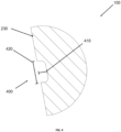
- Figure 1 shows a schematic side view of an exemplary embodiment of an augmentation device 100.
- the augmentation device 100 is formed in one piece and consists of a PMMA bone cement loaded with an antibiotic.
- the augmentation device 100 comprises a solid ring-shaped cone 200 with a proximal cone end 210 and a distal cone end 220, wherein a cone outer diameter, formed by a lateral surface 230 of the cone, decreases from the proximal cone end 210 towards the distal cone end 220.
- the cone outer diameter decreases essentially linearly from the proximal cone end 210 to the distal cone end 220.
- a channel extends through the cone 200 from the proximal cone end 210 to the distal cone end 220 (see Figure 3 ).
- three grooves 400 each extend radially all the way around, dividing the cone into four annular cone segments 250.
- the grooves 400 are arranged in such a way that the cone segments 250 have a substantially equal have a large axial extension.
- the grooves 400 serve as saw guides so that one or more cone segments 250 can be easily and safely severed from the augmentation device 100 using suitable means, for example with a saw.
- a cone size of the augmentation device 100 is adapted. For example, by separating a cone segment 250 at the proximal cone end 210, both the axial extension of the cone 200 is reduced by substantially 25% and a maximum cone outer diameter of the cone 200 is reduced.
- the grooves 400 each extend in a plane which extends perpendicular to a longitudinal axis 205 of the cone 200.
- axial grooves 430 In the lateral surface 230 there are also twelve axial grooves 430 (only six are in Figure 1 can be seen, the remaining six are arranged on a side of the cone 200 opposite the view shown).
- the axial grooves 430 extend over the cone segment 250 at the proximal cone end 210 and partly also over the cone segment 250 distally adjacent to it.
- All axial grooves 440 are connected at least to the groove 400 at the proximal cone end 210, with four of the axial grooves 440 opening into this groove 400, while the remaining axial grooves 400 extend further in the direction of the distal cone end 220 beyond the groove 400 at the proximal cone end 210.
- the axial grooves 440 form cone sections 270 (provided with a reference symbol only as an example) with the groove 400 at the proximal cone end 210 and/or with the connecting grooves 440, which can be easily and safely separated from the cone 200, for example by sawing, and allow improved adaptation to the anatomical conditions of a patient.
- Figure 2 shows the augmentation device 100 from Figure 1 in a side view rotated by 90° around the longitudinal axis.
- the axial grooves 430 are arranged symmetrically, so that conical sections 270 (cf. Figure 1 ) can be separated from the cone 200 on two sides at the proximal cone end 210.
- Figure 3 shows the augmentation device 100 from the Figures 1 and 2 in a schematic longitudinal section.
- the channel 300 is formed by a conical inner surface 240 and extends from the proximal conical end 210 through the cone 200 to the distal conical end 220.
- the cone 200 has a conical wall thickness 260 which, apart from slight variations at the proximal cone end 210 and the distal cone end 220, is constant over the entire axial extent.
- the cone wall thickness 260 of the embodiment of the augmentation device 100 shown is 10 mm. It can also be seen that the cone 200 is solid and thus there is no fluid-conducting connection between the cone inner surface 240 and the cone outer surface 230 through the cone 200.
- Figure 4 shows an enlarged section of the schematic longitudinal section of the Figure 3 .
- Figure 4 shows in particular an enlarged longitudinal section through one of the grooves 400 of the augmentation device 100.
- the groove 400 has a groove depth 410 running perpendicular to the lateral surface 230 and a groove width 420 running parallel to the lateral surface 230.
- the groove 40 has a groove depth 410 of 1 mm and a groove width 420 of 2.5 mm.
- Figure 5 shows the augmentation device 100 from the Figures 1 to 4 in a schematic side view with adjusted cone size.
- the cone segment 250 with the largest outer diameter at the proximal cone end 210 was removed so that the augmentation device 100 in Figure 3 has a reduced maximum cone outer diameter.
- a cone section 270 was cut off on both sides of the cone 200 along the middle pair of axial grooves 430 and their connecting groove 440 running on both cone sides (cf. Figure 1 and 2 ).
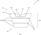
- Figure 6 shows a schematic longitudinal section of another exemplary augmentation device 100'.
- the embodiment of the augmentation device 100' largely corresponds to that described above and in the Figures 1 to 5 shown embodiment, so that to avoid repetition, reference is made to the above description. Modifications of a variant of the embodiment shown in the Figures 1 to 5 The embodiment shown have the same reference numeral with an apostrophe.
- the augmentation device 100' differs from the augmentation device 100 of the Figures 1 to 5 by a porous shell surface 230' made of titanium.
- the shell surface 230' is made entirely of titanium.
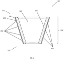
- FIG 7 shows a schematic side view of another exemplary augmentation device 100".
- the embodiment of the augmentation device 100" largely corresponds to the one described above and in the Figures 1 to 5 and Figure 6 shown embodiments, so that in order to avoid repetition, reference is made to the above descriptions. Modifications of a variant of the Figures 1 to 5 and Figure 6 The embodiment shown have the same reference numeral with two apostrophes.
- the augmentation device 100" differs from the augmentation devices 100 and 100' of the Figures 1 to 5 and Figure 6 by means of cone segments 250" which are stepped from one another. Due to the stepped cone segments 250", the outer cone diameter of the augmentation device 100" does not decrease essentially linearly from the proximal cone end 210" to the distal cone end 220", but rather "in a jump" manner between the cone segments 250".
Description
Die Erfindung ist in den Ansprüchen 1 und 9 definiert. Sie betrifft eine Augmentationsvorrichtung umfassend einen ringförmigen Konus, der einen Kanal umgibt, welcher sich von einem proximalen Konusende zu einem distalen Konusende des Konus durch den Konus erstreckt.The invention is defined in claims 1 and 9. It relates to an augmentation device comprising an annular cone surrounding a channel which extends through the cone from a proximal cone end to a distal cone end of the cone.
Die Erfindung betrifft weiterhin ein Verfahren zur Adaption einer Konusgröße einer derartigen Augmentationsvorrichtung.The invention further relates to a method for adapting a cone size of such an augmentation device.
Gegenstand der Erfindung ist insbesondere eine Augmentationsvorrichtung zum Einsatz bei Gelenkendoprothesenoperationen, insbesondere Revisionsgelenkendoprothesenoperationen. Die erfindungsgemäße Augmentationsvorrichtung ist dazu geeignet, debridiertes Knochengewebe zu verstärken oder gar teilweise zu ersetzen und so eine sichere und stabile Verankerung einer Gelenkendoprothese, insbesondere einer Revisionsendoprothese, in einem Knochenkanal zu ermöglichen. Zudem dient die erfindungsgemäße Augmentationsvorrichtung insbesondere einer gleichmäßigen Krafteinleitung in das umgebende Knochengewebe im Zuge einer Implantation einer Gelenkendoprothese, insbesondere einer RevisionsgelenkendoprotheseThe subject of the invention is in particular an augmentation device for use in joint endoprosthesis operations, in particular revision joint endoprosthesis operations. The augmentation device according to the invention is suitable for reinforcing debrided bone tissue or even partially replacing it and thus enabling a safe and stable anchoring of a joint endoprosthesis, in particular a revision endoprosthesis, in a bone canal. In addition, the augmentation device according to the invention serves in particular for a uniform introduction of force into the surrounding bone tissue during the implantation of a joint endoprosthesis, in particular a revision joint endoprosthesis.
In der orthopädischen Chirurgie müssen leider in einem gewissen Umfang septische Revisionen von mit Mikroorganismen infizierten Gelenkendoprothesen vorgenommen werden. Dabei werden die infizierten Gelenkendoprothesen explantiert und das infizierte beziehungsweise nekrotische Gewebe abgetragen. Dieses Abtragen von infiziertem/nekrotischem Gewebe wird als Debridement bezeichnet. Dabei kann es im Bereich der entfernten Gelenkendoprothese zu einem substanziellen Verlust an Knochengewebe, insbesondere bei vorgeschädigter Knochengewebesubstanz, beispielsweise durch Osteoporose, kommen, was zu Problemen bei der Verankerung einer Revisionsgelenkendoprothese führen kann. Um das verbliebene Knochengewebe zu verstärken oder teilweise gar zu ersetzen und eine möglichst gleichmäßige Krafteinleitung in das verbliebene Knochengewebe beim Einsatz der Revisionsgelenkendoprothese zu gewährleisten, besteht eine mögliche Behandlungsoption in einem Einsatz einer Augmentationsvorrichtung in Form eines Metallkonus. Dazu wird das infizierte Knochengewebe abgetragen und die dadurch entstandene Kavität durch Einsetzten der Augmentationsvorrichtung aufgefüllt. Die konusförmige Ausgestaltung der Augmentationsvorrichtung dient dazu, einen Schaft einer Gelenkendoprothese, beziehungsweise einer Revisionsgelenkendoprothese, in einen zentral verlaufenden Kanal der Augmentationsvorrichtung aufzunehmen und dort, beispielsweise unter Einsatz von Knochenzement, zu verankern. Die Augmentationsvorrichtung selbst ist so gestaltet, dass sie in die durch das Debridement entstandene Kavität eingebracht werden kann. Eine derartige Augmentationsvorrichtung ist beispielsweise in der Patentschrift
Üblicherweise weisen die im Markt erhältlichen Augmentationsvorrichtungen eine definierte, vorbestimmte Größe auf und können nicht an die jeweilige anatomische Gegebenheit des Patienten angepasst werden. Daher werden im Markt Augmentationsvorrichtungen unterschiedlicher Größe angeboten.Usually, the augmentation devices available on the market have a defined, predetermined size and cannot be adapted to the individual anatomical condition of the patient. Therefore, augmentation devices of different sizes are offered on the market.
In der Patentschrift
Als nachteilig ist bei einer Verwendung von Gelenken, insbesondere Biegegelenken anzusehen, dass die Anpassung der Größe, insbesondere des Außendurchmessers, der Augmentationsvorrichtung mit einer deutlichen Verformung der Augmentationsvorrichtung einhergeht. Die Augmentationsvorrichtung weist durch die Anpassung der Größe einen "Knick" auf, welcher die Einpassung der Augmentationsvorrichtung in den Knochen des Patienten erschwert und sich nachteilig bei der Implantation der Gelenkendoprothese, beziehungsweise der Revisionsgelenkendoprothese, auswirken kann. Zudem ist eine Anpassung der Größe der Augmentationsvorrichtung nur in einem geringen Umfang möglich. Eine Anpassung der axialen Erstreckung der Augmentationsvorrichtung ist im Zuge einer laufenden Operation in einem Operationssaal nicht möglich.A disadvantage when using joints, particularly flexible joints, is that adjusting the size, particularly the outer diameter, of the augmentation device is accompanied by a significant deformation of the augmentation device. The augmentation device has a "kink" due to the adjustment of the size, which makes it difficult to fit the augmentation device into the patient's bone and can have a detrimental effect on the implantation of the joint endoprosthesis or the revision joint endoprosthesis. In addition, the size of the augmentation device can only be adjusted to a limited extent. Adjusting the axial extension of the augmentation device is not possible during an ongoing operation in an operating room.
In der Patentanmeldung
Als nachteilig gestaltet sich an einer Augmentationsvorrichtung aus einem Metallgewebe, dass dieses nicht formstabil ist, was sowohl die Stabilität einer damit implantierten Prothese negativ beeinträchtigt. Zudem kann die bei der Implantation der Prothese benötigte Krafteinwirkung, welche auf die Augmentationsvorrichtung und das mit ihr verbundene Gewebe des Patienten einwirkt, nicht gleichmäßig übertragen werden. Insbesondere Letzteres kann zu Schädigungen am Knochengewebe des Patienten führen. Zudem kann das Abschneiden zu scharfkantigen Gewebesträngen führen, welche für den Operateur und den Patienten ein Verletzungsrisiko darstellen.A disadvantage of an augmentation device made of metal mesh is that it is not dimensionally stable, which negatively affects the stability of a prosthesis implanted with it. In addition, the force required to implant the prosthesis, which acts on the augmentation device and the patient's tissue connected to it, cannot be transmitted evenly. The latter in particular can lead to damage to the patient's bone tissue. In addition, cutting off can lead to sharp-edged strands of tissue, which pose a risk of injury to the surgeon and the patient.
Ein Augment mit zwei längenanpassbaren Beinen wird in der Patentanmeldung
Wünschenswert ist daher eine Augmentationsvorrichtung, welche formstabil ist und einfach und schnell in ihrer Größe, insbesondere ihres Durchmessers und ihrer Länge, anpassbar ist. Die Anpassung der Größe soll ohne eine Verformung der Augmentationsvorrichtung möglich sein. Weiterhin soll die Anpassung der Größe mit Mitteln durchführbar sein, welche im Zuge einer orthopädischen Operation üblicherweise verwendet werden, wie beispielsweise Sägen.What is therefore desirable is an augmentation device that is dimensionally stable and can be easily and quickly adjusted in size, particularly in diameter and length. The size should be able to be adjusted without deforming the augmentation device. Furthermore, the size should be able to be adjusted using means that are usually used in orthopedic surgery, such as saws.
Eine Aufgabe der vorliegenden Erfindung ist es, einen oder mehrere der sich aus dem Stand der Technik ergebenen Nachteile zumindest teilweise zu überwinden.An object of the present invention is to at least partially overcome one or more of the disadvantages resulting from the prior art.
Insbesondere soll eine Augmentationsvorrichtung bereitgestellt werden, welche formstabil ist sowie einfach und schnell in ihrer Größe an die anatomischen Gegebenheiten eines Patienten angepasst werden kann. Weiterhin soll die Augmentationsvorrichtung bei einer Anpassung der Größe nicht verformt werden. Weiterhin soll die Augmentationsvorrichtung nach einer Anpassung der Größe kein Verletzungsrisiko darstellen.In particular, an augmentation device should be provided which is dimensionally stable and whose size can be easily and quickly adjusted to the anatomical conditions of a patient. Furthermore, the augmentation device should not be deformed when the size is adjusted. Furthermore, the augmentation device should not pose a risk of injury after the size has been adjusted.
Ein weiteres Ziel der Erfindung ist es ein Verfahren zur Verfügung zu stellen, mit dem eine Augmentationsvorrichtung in ihrer Größe angepasst werden kann und welches Beschränkungen herkömmlicher Implantationsverfahren vermeidet.Another object of the invention is to provide a method by which an augmentation device can be adjusted in size and which avoids limitations of conventional implantation methods.
Ein Beitrag zur mindestens teilweisen Erfüllung mindestens einer der zuvor genannten Aufgaben wird durch die Merkmale der unabhängigen Ansprüche geleistet. Die abhängigen Ansprüche stellen bevorzugte Ausführungsformen bereit, die zur mindestens teilweisen Erfüllung mindestens einer der Aufgaben beitragen.A contribution to at least partially fulfilling at least one of the aforementioned tasks is made by the features of the independent claims. The dependent Claims provide preferred embodiments that contribute to at least partially fulfilling at least one of the objects.
Eine erste Ausführungsform der Erfindung gemäß Anspruch 1 ist eine Augmentationsvorrichtung umfassend einen ringförmigen Konus, der einen Kanal umgibt, welcher sich von einem proximalen Konusende zu einem distalen Konusende des Konus durch den Konus erstreckt, wobei der Konus zu mindestens 50 Volumenprozent, vorzugsweise zu mindestens 70 Volumenprozent, weiter bevorzugt zu mindestens 90 Volumenprozent, bezogen auf das Gesamtvolumen des Konus aus einem biokompatiblen Polymer besteht und durch mindestens drei, bevorzugt drei bis acht, weiter bevorzugt drei bis sechs, weiter bevorzugt drei bis fünf, in einer dem Kanal gegenüberliegenden Konusmantelfläche radial umlaufende Nuten in ringförmige Konussegmente unterteilt ist,
wobei die Nuten eine Nutentiefe von mindestens 1 mm und eine Nutenbreite von mindestens 1 mm aufweisen und Sägeführungen bilden, um eine Konusgröße des Konus durch Abtrennung eines oder mehrerer Konussegmente zu adaptieren.A first embodiment of the invention according to claim 1 is an augmentation device comprising an annular cone which surrounds a channel which extends from a proximal cone end to a distal cone end of the cone through the cone, wherein the cone consists of at least 50 percent by volume, preferably at least 70 percent by volume, more preferably at least 90 percent by volume, based on the total volume of the cone, of a biocompatible polymer and is divided into annular cone segments by at least three, preferably three to eight, more preferably three to six, more preferably three to five, radially encircling grooves in a cone surface opposite the channel,
wherein the grooves have a groove depth of at least 1 mm and a groove width of at least 1 mm and form saw guides to adapt a cone size of the cone by separating one or more cone segments.
Im Folgenden werden bevorzugte, teilweise durch die abhängigen Ansprüche abgebildete, Ausführungsformen eins bis acht beschrieben.In the following, preferred embodiments one to eight, partly depicted by the dependent claims, are described.
In einer Ausführungsform der Augmentationsvorrichtung ist die Konusmantelfläche zumindest abschnittweise aufgeraut oder porös. Diese Ausführungsform ist eine zweite Ausführungsform der Erfindung, welche vorzugsweise von der ersten Ausführungsform der Erfindung abhängt.In one embodiment of the augmentation device, the conical surface is roughened or porous at least in sections. This embodiment is a second embodiment of the invention, which preferably depends on the first embodiment of the invention.
In einer Ausführungsform der Augmentationsvorrichtung ist die Konusmantelfläche zumindest zu 70 Flächenprozent, bevorzugt zumindest zu 80 Flächenprozent, weiter bevorzugt zumindest zu 90 Flächenprozent, bezogen auf die gesamte Konusmantelfläche aus Tantal, einer Tantallegierung, Titan, einer Titanlegierung oder aus Edelstahl gebildet. Diese Ausführungsform ist eine dritte Ausführungsform der Erfindung, welche vorzugsweise von der ersten oder der zweiten Ausführungsform der Erfindung abhängt.In one embodiment of the augmentation device, the cone surface is formed to at least 70 area percent, preferably at least 80 area percent, more preferably at least 90 area percent, based on the entire cone surface from tantalum, a tantalum alloy, titanium, a titanium alloy or stainless steel. This embodiment is a third embodiment of the invention, which preferably depends on the first or second embodiment of the invention.
In einer Ausführungsform der Augmentationsvorrichtung ist das biokompatible Polymer ein PMMA-Knochenzement. Diese Ausführungsform ist eine vierte Ausführungsform der Erfindung, welche vorzugsweise von einer der vorhergehenden Ausführungsformen der Erfindung abhängt.In one embodiment of the augmentation device, the biocompatible polymer is a PMMA bone cement. This embodiment is a fourth embodiment of the invention, which preferably depends on one of the preceding embodiments of the invention.
In einer Ausführungsform der Augmentationsvorrichtung enthält der PMMA-Knochenzement mindestens ein Antibiotikum. Diese Ausführungsform ist eine fünfte Ausführungsform der Erfindung, welche vorzugweise von der vierten Ausführungsform der Erfindung abhängt.In one embodiment of the augmentation device, the PMMA bone cement contains at least one antibiotic. This embodiment is a fifth embodiment of the invention, which preferably depends on the fourth embodiment of the invention.
In einer Ausführungsform der Augmentationsvorrichtung weist der Konus in einer dem Kanal zugewandten Konusinnenfläche radial umlaufende Innennuten auf, welche den Nuten gegenüberliegend, insbesondere radial gegenüberliegend, angeordnet sind. Diese Ausführungsform ist eine sechste Ausführungsform der Erfindung, welche vorzugweise von einer der vorhergehenden Ausführungsformen der Erfindung abhängt.In one embodiment of the augmentation device, the cone has radially encircling inner grooves in a cone inner surface facing the channel, which are arranged opposite the grooves, in particular radially opposite them. This embodiment is a sixth embodiment of the invention, which preferably depends on one of the preceding embodiments of the invention.
In einer Ausführungsform der Augmentationsvorrichtung weist die Konusmantelfläche zumindest zwei axial verlaufende Axialnuten mit einer Axialnutentiefe von mindestens 1 mm und einer Axialnutenbreite von mindestens 1 mm auf, welche jeweils zumindest mit einer der Nuten verbunden sind. Diese Ausführungsform ist eine siebte Ausführungsform der Erfindung, welche vorzugsweise von einer der vorhergehenden Ausführungsformen der Erfindung abhängt.In one embodiment of the augmentation device, the conical surface has at least two axially extending axial grooves with an axial groove depth of at least 1 mm and an axial groove width of at least 1 mm, which are each connected to at least one of the grooves. This embodiment is a seventh embodiment of the invention, which preferably depends on one of the preceding embodiments of the invention.
In einer Ausführungsform der Augmentationsvorrichtung sind die Konussegmente stufenartig voneinander abgesetzt. Diese Ausführungsform ist eine achte Ausführungsform der Erfindung, welche vorzugsweise von einer der vorhergehenden Ausführungsformen der Erfindung abhängt.In one embodiment of the augmentation device, the cone segments are spaced apart from one another in steps. This embodiment is an eighth embodiment of the invention, which preferably depends on one of the preceding embodiments of the invention.
Eine neunte Ausführungsform der Erfindung ist ein Verfahren gemäß Anspruch 9 zur Adaption einer Konusgröße einer Augmentationsvorrichtung nach einer der vorhergehenden Ausführungsformen der Erfindung, umfassend einen Schritt eines Abtrennens eines oder mehrerer Konussegmente am proximalen Konusende, am distalen Konusende oder am proximalen und am distalen Konusende durch Sägen, Schneiden oder Abbrechen entlang der radial umlaufenden Nut oder Nuten.A ninth embodiment of the invention is a method according to claim 9 for adapting a cone size of an augmentation device according to one of the preceding embodiments of the invention, comprising a step of separating one or more cone segments at the proximal cone end, at the distal cone end or at the proximal and distal cone ends by sawing, cutting or breaking off along the radially circumferential groove or grooves.
Eine Ausführungsform des Verfahrens zur Adaption der Konusgröße einer Augmentationsvorrichtung nach der siebten Ausführungsform der Erfindung umfasst einen Schritt eines Abtrennens eines Konusteilstücks aus dem Konus durch Sägen, Schneiden oder Abbrechen entlang zweier der axial verlaufenden Axialnuten. Diese Ausführungsform ist eine zehnte Ausführungsform der Erfindung, welche vorzugsweise von der neunten Ausführungsform der Erfindung abhängt.An embodiment of the method for adapting the cone size of an augmentation device according to the seventh embodiment of the invention comprises a step of separating a cone section from the cone by sawing, cutting or breaking off along two of the axially extending axial grooves. This embodiment is a tenth embodiment of the invention, which preferably depends on the ninth embodiment of the invention.
In der vorliegenden Beschreibung beinhalten Bereichsangaben auch die als Grenzen genannten Werte. Eine Angabe der Art "im Bereich von X bis Y" in Bezug auf eine Größe A bedeutet folglich, dass A die Werte X, Y und Werte zwischen X und Y annehmen kann. Einseitig begrenzte Bereiche der Art "bis zu Y" für eine Größe A bedeuten entsprechend als Wert Y und kleiner als Y.In the present description, ranges also include the values referred to as limits. A statement of the type "in the range from X to Y" in relation to a size A therefore means that A can assume the values X, Y and values between X and Y. Unilaterally limited ranges of the type "up to Y" for a size A correspondingly mean the value Y and less than Y.
Einige der beschriebenen Merkmale sind mit dem Begriff "im Wesentlichen" verknüpft. Der Begriff "im Wesentlichen" ist so zu verstehen, dass unter realen Bedingungen und Fertigungstechniken eine mathematisch exakte Auslegung von Begrifflichkeiten wie "Überlagerung", "senkrecht", "Durchmesser" oder "Parallelität" nie exakt, sondern nur innerhalb gewisser fertigungstechnischer Fehlertoleranzen gegeben sein kann. Beispielsweise schließen "im Wesentlichen senkrechte Achsen" einen Winkel von 85 Grad bis 95 Grad zueinander ein und "im Wesentlichen gleiche Volumen" umfassen eine Abweichung von bis zu 5 Volumen-%. Eine "im Wesentlichen aus Kunststoff bestehende Vorrichtung" umfasst beispielsweise einen Kunststoffanteil von ≥95 bis ≤100 Gewichts-%. Eine "im Wesentlichen vollständige Befüllung eines Volumens B" umfasst beispielsweise eine Befüllung von ≥95 bis ≤100 Volumen-% des Gesamtvolumens von B.Some of the features described are linked to the term "essentially". The term "essentially" is to be understood in such a way that under real conditions and manufacturing techniques, a mathematically exact interpretation of terms such as "superposition", "vertical", "diameter" or "parallelism" can never be exact, but only within certain manufacturing error tolerances. For example, "essentially vertical axes" enclose an angle of 85 degrees to 95 degrees to one another and "essentially equal volumes" include a deviation of up to 5% by volume. A "device consisting essentially of plastic", for example, comprises a plastic content of ≥95 to ≤100% by weight. A "essentially complete filling of a volume B", for example, comprises a filling of ≥95 to ≤100% by volume of the total volume of B.
Die Begriffe "proximal" und "distal" dienen lediglich der Bezeichnung der räumlich entgegengesetzten Enden der Augmentationsvorrichtung, des Konus, oder anderer Struktureinheiten der Augmentationsvorrichtung und des Augmentationssystems und erlauben keinen Rückschluss auf die Orientierung der in einen menschlichen Körper implantieren Augmentationsvorrichtung. "Distal zu ..." und "proximal zu..." oder ähnliche Formulierungen drücken entsprechend lediglich die räumliche Anordnung zweier Struktureinheiten der Augmentationsvorrichtung und des Augmentationssystems zueinander aus.The terms "proximal" and "distal" are used only to designate the spatially opposite ends of the augmentation device, the cone, or other structural units of the augmentation device and the augmentation system and do not allow any conclusions to be drawn about the orientation of the augmentation device implanted in a human body. "Distal to ..." and "proximal to ..." or similar formulations accordingly only express the spatial arrangement of two structural units of the augmentation device and the augmentation system in relation to one another.
Ein erster Gegenstand der Erfindung betrifft eine Augmentationsvorrichtung umfassend einen ringförmigen Konus, der einen Kanal umgibt, welcher sich von einem proximalen Konusende zu einem distalen Konusende des Konus durch den Konus erstreckt, wobei der Konus zu mindestens 50 Volumenprozent, vorzugsweise zu mindestens 70 Volumenprozent, weiter bevorzugt zu mindestens 90 Volumenprozent, bezogen auf das Gesamtvolumen des Konus aus einem biokompatiblen Polymer besteht und durch mindestens drei, bevorzugt drei bis acht, weiter bevorzugt drei bis sechs, weiter bevorzugt drei bis fünf, in einer dem Kanal gegenüberliegenden Konusmantelfläche radial umlaufende Nuten in ringförmige Konussegmente unterteilt ist,
wobei die Nuten eine Nutentiefe von mindestens 1 mm und eine Nutenbreite von mindestens 1 mm aufweisen und Sägeführungen bilden, um eine Konusgröße des Konus durch Abtrennung eines oder mehrerer Konussegmente zu adaptieren.A first subject of the invention relates to an augmentation device comprising an annular cone which surrounds a channel which extends from a proximal cone end to a distal cone end of the cone through the cone, wherein the cone consists of at least 50 volume percent, preferably at least 70 volume percent, more preferably at least 90 volume percent, based on the total volume of the cone, a biocompatible polymer and is divided into annular cone segments by at least three, preferably three to eight, more preferably three to six, more preferably three to five, radially encircling grooves in a cone surface opposite the channel,
wherein the grooves have a groove depth of at least 1 mm and a groove width of at least 1 mm and form saw guides to adapt a cone size of the cone by separating one or more cone segments.
Die Augmentationsvorrichtung weist einen ringförmigen Konus auf. Ein Konus ist ein kegelartiges, insbesondere kegelstumpfartig, geformtes Bauteil mit einem proximalen Konusende und einem dem proximalen Konusende axial gegenüberliegendem distalen Konusende, wobei sich ein Konusaußendurchmesser von einem Konusende zum anderen Konusende hin verringert. Vorzugsweise verjüngt sich der erfindungsgemäße Konus vom proximalen Konusende in Richtung des distalen Konusende.The augmentation device has an annular cone. A cone is a conical, in particular truncated cone-shaped, component with a proximal cone end and a distal cone end axially opposite the proximal cone end, with a cone outer diameter decreasing from one cone end to the other cone end. The cone according to the invention preferably tapers from the proximal cone end towards the distal cone end.
Der Konus ist ringförmig, oder in anderen Worten rohrartig, ausgestaltet. Dadurch umschließt der Konus einen Kanal, welcher sich axial durch den Konus vom proximalen Konusende bis zum distalen Konusende erstreckt. Der Kanal wird durch eine dem Kanal zugewandten Konusinnenfläche ausgebildet. Der Begriff "ringförmig" umfasst in einer axialen Aufsicht auf den Konus Körper mit einem kreisförmigen, elliptischen, eckigen, beispielweise vier-, fünf- oder sechseckigen, und unregelmäßigen Umfang, wobei Körper mit elliptischem Umfang aufgrund einer besseren Implantierbarkeit in einen Patienten, insbesondere in einen Knochenkanal eines Patienten, bevorzugt sind.The cone is ring-shaped, or in other words tube-like. The cone thus encloses a channel which extends axially through the cone from the proximal cone end to the distal cone end. The channel is formed by an inner cone surface facing the channel. The term "ring-shaped" includes, in an axial view of the cone, bodies with a circular, elliptical, angular, for example square, pentagonal or hexagonal, and irregular circumference, with bodies with an elliptical circumference being preferred due to better implantability in a patient, in particular in a patient's bone canal.
Der Kanal dient der Aufnahme und Fixierung eines Schafts einer Gelenkendoprothese oder einer Revisionsgelenkendoprothese. Dafür kann der Schaft der entsprechenden Endoprothese in den Kanal, insbesondere vom proximalen Konusende aus, eingebracht werden. Der Kanal weist einen Kanaldurchmesser auf, welcher von einem Konusinnendurchmesser bestimmt ist. In einer Ausgestaltungsform kann der Konusinnendurchmesser über die gesamte axiale Erstreckung des Kanals beziehungsweise des Konus konstant ausgestaltet sein. In einer weiteren Ausgestaltungsform verringert sich der Konusinnendurchmesser gleichlaufend zum Konusaußendurchmesser vom proximalen Konusende bis zum distalen Konusende. In dieser Ausgestaltungsform weist der Konus eine über die gesamte axiale Erstreckung des Konus im Wesentlichen gleich starke Konuswanddicke auf.The channel serves to accommodate and fix a shaft of a joint endoprosthesis or a revision joint endoprosthesis. For this purpose, the shaft of the corresponding endoprosthesis can be introduced into the channel, in particular from the proximal end of the cone. The channel has a channel diameter which is determined by an inner diameter of the cone. In one embodiment, the inner diameter of the cone can be constant over the entire axial extension of the channel or the cone. In another embodiment, the inner diameter of the cone decreases in parallel with the outer diameter of the cone from the proximal end of the cone to the distal end of the cone. In this embodiment, the cone has a cone wall thickness which is essentially the same over the entire axial extension of the cone.
Die Konuswanddicke kann beispielsweise in einem Bereich von 2 bis 30 mm, bevorzugt 2 bis 15 mm, weiter bevorzugt 2 bis 10 mm, liegen.The cone wall thickness can, for example, be in a range of 2 to 30 mm, preferably 2 to 15 mm, more preferably 2 to 10 mm.
Die axiale Erstreckung des Konus kann beispielsweise in einem Bereich von 30 mm bis 50 mm, so dass die Augmentationsvorrichtung für eine möglichst breite Bandbreite von unterschiedlichen anatomischen Gegebenheiten von Patienten geeignet oder anpassbar ist.The axial extension of the cone can, for example, be in a range of 30 mm to 50 mm, so that the augmentation device is suitable or adaptable for the widest possible range of different anatomical conditions of patients.
Der Konus weist eine dem Kanal gegenüberliegende, und somit außenliegende, Konusmantelfläche auf. In der Konusmantelfläche verlaufen mindestens drei, vorzugsweise drei bis acht, weiter bevorzugt drei bis sechs, weiter bevorzugt drei bis fünf, radial umlaufende Nuten, welche den Konus in ringförmige Konussegmente unterteilen.The cone has a conical surface opposite the channel and thus on the outside. At least three, preferably three to eight, more preferably three to six, more preferably three to five, radially encircling grooves run in the conical surface, which divide the cone into annular conical segments.
Nuten sind längliche Vertiefungen in der Konusmantelfläche. Die Nuten sind radial umlaufend und erstrecken sich vorzugsweise im Wesentlichen jeweils in einer Ebene, welche jeweils vorzugsweise im Wesentlichen senkrecht zu einer Längsachse der Augmentationsvorrichtung liegt. Die Nuten verlaufen somit im Wesentlichen "horizontal" zur Längsachse der Augmentationsvorrichtung.Grooves are elongated depressions in the cone surface. The grooves are radially circumferential and preferably extend essentially in one plane, which preferably lies essentially perpendicular to a longitudinal axis of the augmentation device. The grooves thus run essentially "horizontally" to the longitudinal axis of the augmentation device.
Die Konuswanddicke ist im Bereich der Nuten reduziert, so dass der Konus durch die Nuten in ringförmige Konussegmente unterteilt ist. Beispielsweise unterteilen drei Nuten den Konus in vier Konussegmente und vier Nuten den Konus in fünf Konussegmente.The cone wall thickness is reduced in the area of the grooves so that the cone is divided into ring-shaped cone segments by the grooves. For example, three grooves divide the cone into four cone segments and four grooves divide the cone into five cone segments.
Die Nuten erleichtern das Abtrennen einzelner Konussegmente, so dass die Augmentationsvorrichtung eine adaptierbare Konusgröße, insbesondere einen adaptierbaren maximalen und/oder minimalen Konusaußendurchmesser und eine adaptierbare axiale Erstreckung des Konus, aufweist.The grooves facilitate the separation of individual cone segments, so that the augmentation device has an adaptable cone size, in particular an adaptable maximum and/or minimum cone outer diameter and an adaptable axial extension of the cone.
Die Nuten besitzen eine Nutentiefe von mindestens 1 mm und eine Nutenbreite von mindestens 1 mm, so dass die Nuten als Sägeführungen für Mittel zum Abtrennen einzelner Konussegmente, beispielsweise durch Sägen, Schneiden oder Abbrechen dienen. Geeignete Mittel zum Abtrennen sind beispielsweise Sägen, insbesondere Kreissägen, Zangen, und Scheren. Zum Abbrechen von Konussegmenten können beispielsweise Bruchkanten dienen. Um die strukturelle Stabilität des Konus nicht negativ zu beeinträchtigen, ist es bevorzugt, dass die Nutentiefe nicht mehr als einem Viertel (25%) der Konuswanddicke entspricht.The grooves have a groove depth of at least 1 mm and a groove width of at least 1 mm, so that the grooves serve as saw guides for means for separating individual cone segments, for example by sawing, cutting or breaking off. Suitable means for separating are, for example, saws, in particular circular saws, pliers and scissors. For example, breaking edges can be used to break off cone segments. In order not to negatively affect the structural stability of the cone, it is preferred that the groove depth does not correspond to more than a quarter (25%) of the cone wall thickness.
Um eine gute Sägeführung für Mittel zum Abtrennen einzelner Konussegmente darzustellen, ist es bevorzugt, dass die Nutenbreite nicht mehr als 5 mm, bevorzugt nicht mehr als 4 mm, weiter bevorzugt nicht mehr als 3 mm entspricht.In order to provide good saw guidance for means for separating individual cone segments, it is preferred that the groove width is not more than 5 mm, preferably not more than 4 mm, more preferably not more than 3 mm.
Die Nuten zeigen dabei dem Anwender geeignete Stellen zum Abtrennen einzelner Konussegmente an und erleichtern insbesondere ein kontrolliertes und sicheres Abtrennen einzelner Konussegmente entlang der entsprechenden Nut oder Nuten. Insbesondere beim Absägen und Abschneiden einzelner Konussegmente wird durch die Nuten ein Verletzungsrisiko für den Operateur, beispielsweise durch eine verringerte Gefahr eines Abrutschens einer Säge auf der Mantelfläche des Konus, vermindert. Die Nuten können darüber hinaus als Sollbruchstellen zum kontrollierten Abbrechen einzelner Konussegmente verwendet werden.The grooves show the user suitable places for separating individual cone segments and in particular facilitate the controlled and safe separation of individual cone segments along the corresponding groove or grooves. In particular when sawing and cutting off individual cone segments, the grooves reduce the risk of injury to the operator, for example by reducing the risk of a saw slipping on the surface of the cone. The grooves can also be used as predetermined breaking points for the controlled breaking off of individual cone segments.
In einer Ausgestaltungsform erstrecken sich die Nuten jeweils um mindestens 90% des jeweiligen Konusaußendurchmessers. In einer weiteren Ausgestaltungsform erstrecken sich die Nuten jeweils um mindestens 95% des jeweiligen Konusaußendurchmessers. Vorzugsweise umlaufen die Nuten jeweils den gesamten jeweiligen Konusaußendurchmessers des Konus. Letzteres entspricht Nuten in Form eines geschlossenen "Rings".In one embodiment, the grooves each extend by at least 90% of the respective cone outer diameter. In another embodiment, the grooves each extend by at least 95% of the respective cone outer diameter. Preferably, the grooves each run around the entire respective cone outer diameter of the cone. The latter corresponds to grooves in the form of a closed "ring".
Vorzugsweise sind die Nuten im Wesentlichen gleichmäßig über die Mantelfläche verteilt, so dass die einzelnen Konussegmente im Wesentlichen eine gleiche axiale Erstreckung aufweisen.Preferably, the grooves are distributed substantially uniformly over the lateral surface, so that the individual cone segments have substantially the same axial extension.
Um die Augmentationsvorrichtung möglichst gut an die anatomischen Gegebenheiten eines Patienten anpassen zu können, können die Konussegment unterschiedliche axiale Erstreckungen aufweisen. Beispielsweise sind die Nuten so angeordnet, dass die Konussegmente eine axiale Erstreckung im Bereich von 1 mm bis 10 mm, bevorzugt im Bereich von 2 mm bis 8 mm aufweisen.In order to be able to adapt the augmentation device as well as possible to the anatomical conditions of a patient, the cone segments can have different axial extensions. For example, the grooves are arranged so that the cone segments have an axial extension in the range of 1 mm to 10 mm, preferably in the range of 2 mm to 8 mm.
Vorzugsweise ist der Konus massiv ausgestaltet, so dass die Konusinnenfläche und die Konusmantelfläche nicht durch den Konus hindurch, beispielsweise über eine Durchführung oder eine Leitung, miteinander fluidleitend verbunden sind. Ein massiver Konus verbessert die strukturelle Integrität der Augmentationsvorrichtung und erlaubt so eine verbesserte Krafteinleitung im Zuge einer Operation.Preferably, the cone is designed to be solid, so that the inner surface of the cone and the outer surface of the cone are not connected to one another in a fluid-conducting manner through the cone, for example via a feedthrough or a line. A solid cone improves the structural integrity of the augmentation device and thus allows for improved force introduction during an operation.
Der Konus besteht bezogen auf das Gesamtvolumen des Konus zumindest zu 50 Volumenprozent, bevorzugt zumindest zu 70 Volumenprozent, weiter bevorzugt zumindest zu 90 Volumenprozent aus einem biokompatiblen Polymer. Vorzugsweise ist die Konusinnenfläche vollständig aus dem biokompatiblen Polymer gebildet. In einer Ausgestaltungsform besteht der Konus im Wesentlichen vollständig aus einem biokompatiblen Polymer. Ein Vorteil eines biokompatiblen Polymers ist, dass dieses ein schnelles Anpassen der Konusgröße durch Abtrennen einzelner Konussegmente erlaubt und gleichzeitig dem Konus eine strukturelle Stabilität und damit Formstabilität gibt, welche eine gleichmäßige Kraftübertragung beim Implantieren der Augmentationsvorrichtung und einer entsprechenden Prothese ermöglicht. Zudem ergeben sich nach dem Abtrennen einzelner Konussegmente bei einem biokompatiblen Polymer lediglich Kanten, welche keine oder lediglich geringe Verletzungsgefahr für den Operateur darstellen. Weiter kann ein biokompatibles Polymer mit während einer chirurgischen Operation ohnehin zugänglichen Mitteln, wie beispielsweise Sägen, insbesondere Knochensägen, oder Scheren, bearbeitet werden, um die Konusgröße zu adaptieren.The cone consists of at least 50 volume percent, preferably at least 70 volume percent, more preferably at least 90 volume percent of a biocompatible polymer based on the total volume of the cone. Preferably, the inner surface of the cone is formed entirely from the biocompatible polymer. In one embodiment, the cone consists essentially entirely of a biocompatible polymer. One advantage of a biocompatible polymer is that it allows the cone size to be quickly adjusted by separating individual cone segments and at the same time gives the cone structural stability and thus dimensional stability, which enables uniform force transmission when implanting the augmentation device and a corresponding prosthesis. In addition, after separating individual cone segments, a biocompatible polymer only produces edges that pose no or only a small risk of injury to the surgeon. Furthermore, a biocompatible polymer can be processed with means that are already accessible during a surgical operation, such as saws, in particular bone saws, or scissors, in order to adapt the cone size.
Beispiele für biokompatible Polymere sind PEEK (Polyetherketon), PES (Polyethersulfon), Polyamide und Polyimide, wobei bei den Polyamiden Polyamid-12 bevorzugt ist.Examples of biocompatible polymers are PEEK (polyether ketone), PES (polyether sulfone), polyamides and polyimides, with polyamide-12 being preferred among the polyamides.
Eine Ausführungsform der Augmentationsvorrichtung ist dadurch gekennzeichnet, dass das biokompatible Polymer ein PMMA-Knochenzement ist. Da üblicherweise die Befestigung einer Prothese im Kanal der Augmentationsvorrichtung mittels eines PMMA-Knochenzements erfolgt, bittet ein Konus ebenfalls aus einem PMMA-Knochenzement eine möglichst hohe Kompatibilität. Um die Kompatibilität mit dem zur Befestigung einer Prothese benutzten PMMA-Knochenzement zu erhöhen, ist die Konusinnenfläche bevorzugt im Wesentlichen vollständig aus einem PMMA-Knochenzement ausgebildet.One embodiment of the augmentation device is characterized in that the biocompatible polymer is a PMMA bone cement. Since the attachment of a prosthesis in the channel of the augmentation device is usually carried out using a PMMA bone cement, a cone also made of a PMMA bone cement offers the highest possible compatibility. In order to increase the compatibility with the PMMA bone cement used to attach a prosthesis, the inner surface of the cone is preferably made essentially completely from a PMMA bone cement.
Der PMMA-Knochenzement kann mit weiteren Materialien beladen sein, wie beispielsweise Füllstoffen oder einem Röntgenopaker, wie beispielsweise Bariumsulft oder Zirkoniumoxid.The PMMA bone cement can be loaded with other materials, such as fillers or a radiopaque agent such as barium sulfate or zirconium oxide.
Eine Ausführungsform der Augmentationsvorrichtung ist dadurch gekennzeichnet, dass der PMMA-Knochenzement mindestens ein Antibiotikum enthält. Beispielsweise kann der PMMA-Knochenzement zwei, drei oder vier Antibiotika enthalten. Beispiele für Antibiotika sind Gentamicin, Tobramycin, Amikacin, Vancomycin, Teicoplanin, Ramoplanin, Daptomycin, Colistin und Meropenem, wobei Gentamycin und/oder Vancomycin bevorzugt ist.An embodiment of the augmentation device is characterized in that the PMMA bone cement contains at least one antibiotic. For example, the PMMA bone cement can contain two, three or four antibiotics. Examples of antibiotics are gentamicin, tobramycin, amikacin, vancomycin, teicoplanin, ramoplanin, daptomycin, colistin and meropenem, with gentamicin and/or vancomycin being preferred.
Vorzugsweise enthält der PMMA-Knochenzement mindestens ein Antibiotikum, insbesondere mindestens Gentamycin oder Vancomycin, und ist im Wesentlichen frei von Röntgenopakern, da Röntgenopaker, insbesondere Zirkoniumoxid, aufgrund ihrer strukturellen Härte ein Abtrennen einzelner Konussegmente erschweren oder behindern könnten, beispielsweise durch ein Abstumpfen der Sägezähne einer Säge beim Abtrennen eines Konussegments entlang einer Nut.Preferably, the PMMA bone cement contains at least one antibiotic, in particular at least gentamicin or vancomycin, and is substantially free of radiopaque agents, since radiopaque agents, in particular zirconium oxide, due to their structural hardness could make it difficult or hinder the separation of individual cone segments, for example by blunting the saw teeth of a saw when separating a cone segment along a groove.
In einer Ausführungsform der Augmentationsvorrichtung ist die Konusmantelfläche glatt ausgestaltet.In one embodiment of the augmentation device, the conical surface is smooth.
Eine Ausführungsform der Augmentationsvorrichtung ist dadurch gekennzeichnet, dass die Konusmantelfläche zumindest abschnittsweise, bevorzugt zumindest zu 80 Flächenprozent, weiter bevorzugt zumindest zu 90 Flächenprozent, jeweils bezogen auf die gesamte Konusmantelfläche, weiter bevorzugt im Wesentlichen vollständig, aufgeraut oder porös, vorzugsweise offen-porös, ist. Insbesondere die Konusmantelfläche zwischen und/oder neben den Nuten ist zumindest abschnittsweise, bevorzugt zumindest zu 80 Flächenprozent, weiter bevorzugt zumindest zu 90 Flächenprozent, jeweils bezogen auf die gesamte Konusmantelfläche, weiter bevorzugt im Wesentlichen vollständig, aufgeraut oder porös, vorzugsweise offen-porös. In einer Ausgestaltungsform ist die Mantelfläche mit Sackbohrlöchern versehen, um eine aufgeraute Mantelfläche bereitzustellen. Die Sackbohrlöcher haben dabei vorzugsweise einen Sackbohrlochdurchmesser m Bereich von 300 µm bis 500 µm. Eine aufgeraute oder poröse, vorzugsweise offen-poröse, Mantelfläche verbessert ein Ein- und/oder Anwachsen von Knochengewebe an und/oder in die Augmentationsvorrichtung und verbessert so die Stabilität der Augmentationsvorrichtung im implantierten Zustand. Eine derartige Mantelfläche bildet spongiöses Knochengewebe nach.One embodiment of the augmentation device is characterized in that the cone surface is roughened or porous, preferably open-porous, at least in sections, preferably at least 80 percent by area, more preferably at least 90 percent by area, in each case based on the entire cone surface, more preferably substantially completely. In particular, the cone surface between and/or next to the grooves is roughened or porous, preferably open-porous, at least in sections, preferably at least 80 percent by area, more preferably at least 90 percent by area, in each case based on the entire cone surface, more preferably substantially completely. In one embodiment, the surface is provided with blind boreholes in order to provide a roughened surface. The blind boreholes preferably have a blind borehole diameter in the range from 300 µm to 500 µm. A roughened or porous, preferably open-porous, surface improves the incorporation and/or growth of bone tissue onto and/or into the augmentation device and thus improves the stability of the augmentation device in the implanted state. Such a surface simulates spongy bone tissue.
Die Mantelfläche kann aus dem biokompatiblen Polymer oder aus anderen biokompatiblen Materialien, wie beispielsweise biokompatiblen Metallen, bestehen oder diese umfassen.The shell surface may consist of or comprise the biocompatible polymer or other biocompatible materials, such as biocompatible metals.
Eine Ausführungsform der Augmentationsvorrichtung ist dadurch gekennzeichnet, dass die Konusmantelfläche zumindest zu 90 Flächenprozent, vorzugsweise zumindest zu 95 Flächenprozent, jeweils bezogen auf die gesamte Konusmantelfläche, weiter bevorzugt im Wesentlichen vollständig, aus Tantal, einer Tantallegierung, Titan, einer Titanlegierung oder aus Edelstahl besteht. Die vorgenannten Materialien verbessern ein Ein- und/oder Anwachsen von Knochengewebe an und/oder in die Augmentationsvorrichtung und verbessern so die Stabilität der Augmentationsvorrichtung im implantierten Zustand.An embodiment of the augmentation device is characterized in that the cone surface consists of at least 90 percent of the area, preferably at least 95 percent of the area, in each case based on the entire cone surface, more preferably essentially completely, of tantalum, a tantalum alloy, titanium, a titanium alloy or stainless steel. The aforementioned materials improve the ingrowth and/or growth of bone tissue to and/or into the augmentation device and thus improve the stability of the augmentation device in the implanted state.
In einer Ausgestaltungsform wird die Mantelfläche aus Tantal, einer Tantallegierung, Titan, einer Titanlegierung oder aus Edelstahl durch ein Beschichtungsverfahren, wie beispielsweise Bedampfen, auf den Konus aus einem biokompatiblen Polymer bereitgestellt. Dabei kann die Schicht aus Tantal, einer Tantallegierung, Titan, einer Titanlegierung oder aus Edelstahl eine Schichtdicke in einem Bereich von 10 µm bis 1000 µm.In one embodiment, the outer surface made of tantalum, a tantalum alloy, titanium, a titanium alloy or stainless steel is provided by a coating process, such as vapor deposition, on the cone made of a biocompatible polymer. The layer made of tantalum, a tantalum alloy, titanium, a titanium alloy or stainless steel can have a layer thickness in a range of 10 µm to 1000 µm.
In einer weiteren Ausgestaltungsform wird die Mantelfläche aus Tantal, einer Tantallegierung, Titan, einer Titanlegierung oder aus Edelstahl als Teilkonus bereitgestellt, welcher mit einem weiteren Teilkonus aus dem biokompatiblen Polymer, beispielsweise durch Verklebung, Verklemmung oder Verschweißung, verbunden wird, um die Augmentationsvorrichtung bereitzustellen. Dabei kann die Schicht aus Tantal, einer Tantallegierung, Titan, einer Titanlegierung oder aus Edelstahl eine Schichtdicke in einem Bereich von 1 mm bis 7 mm.In a further embodiment, the outer surface made of tantalum, a tantalum alloy, titanium, a titanium alloy or stainless steel is provided as a partial cone, which is connected to another partial cone made of the biocompatible polymer, for example by gluing, clamping or welding, in order to provide the augmentation device. The layer made of tantalum, a tantalum alloy, titanium, a titanium alloy or stainless steel can have a layer thickness in a range of 1 mm to 7 mm.
Vorzugsweise besteht die Augmentationsvorrichtung aus einem Konus, welcher zumindest zu 50 Volumenprozent, bevorzugt zumindest zu 70 Volumenprozent, weiter bevorzugt zumindest zu 90 Volumenprozent aus einem biokompatiblen Polymer besteht, wobei der Knochenzement vorzugsweise mindestens ein Antibiotikum enthält, und wobei die restlichen Volumenprozent aus der aus Tantal, einer Tantallegierung, Titan, einer Titanlegierung oder aus Edelstahl bestehenden Konusmantelfläche bestehen.Preferably, the augmentation device consists of a cone which consists of at least 50 percent by volume, preferably at least 70 percent by volume, more preferably at least 90 percent by volume of a biocompatible polymer, wherein the bone cement preferably contains at least one antibiotic, and wherein the remaining percent by volume consists of the cone shell surface consisting of tantalum, a tantalum alloy, titanium, a titanium alloy or stainless steel.
In einer Ausführungsform ist die Konusinnenfläche des Konus glatt ausgeformt.In one embodiment, the inner surface of the cone is smooth.
Eine Ausführungsform der Augmentationsvorrichtung ist dadurch gekennzeichnet, dass der Konus in der dem Kanal zugewandten Konusinnenfläche radial umlaufende Innennuten aufweist, welche den Nuten gegenüberliegend angeordnet sind. Vorzugsweise ist jeder Nut eine gegenüberliegende, insbesondere radial gegenüberliegende, Innennut angeordnet. Die Nut und die ihr gegenüberliegende Innennut verringern die Manteldicke des Konus, so dass einzelne Konussegmente vereinfacht von der Augmentationsvorrichtung, insbesondere durch Sägen, Schneiden oder Abbrechen, abtrennbar sind.One embodiment of the augmentation device is characterized in that the cone has radially encircling inner grooves in the inner cone surface facing the channel, which are arranged opposite the grooves. Preferably, an opposite, in particular radially opposite, inner groove is arranged opposite each groove. The groove and the inner groove opposite it reduce the jacket thickness of the cone, so that individual cone segments can be easily separated from the augmentation device, in particular by sawing, cutting or breaking off.
Innennuten sind, ebenso wie die Nuten, längliche Vertiefungen. Während sich die Nuten in der Konusmantelfläche erstrecken, erstrecken sich die Innennuten hingegen in der Konusinnenfläche. Die Innennuten sind radial umlaufend und erstrecken sich vorzugsweise im Wesentlichen jeweils in einer Ebene, welche jeweils vorzugsweise im Wesentlichen senkrecht zu einer Längsachse der Augmentationsvorrichtung liegt. Die Innennuten verlaufen somit im Wesentlichen "horizontal" zur Längsachse der Augmentationsvorrichtung. Die Nuten und die ihnen jeweils gegenüberliegend angeordneten Innennuten verlaufen vorzugsweise im Wesentlichen in einer gemeinsamen Ebene, welche im Wesentlichen senkrecht zur Längsachse der Augmentationsvorrichtung liegt.Internal grooves are, like the grooves, elongated depressions. While the grooves extend in the cone surface, the internal grooves extend in the cone inner surface. The internal grooves are radially circumferential and preferably extend essentially in one plane, which preferably lies essentially perpendicular to a longitudinal axis of the augmentation device. The internal grooves thus run in the Essentially "horizontal" to the longitudinal axis of the augmentation device. The grooves and the inner grooves arranged opposite them preferably run essentially in a common plane which is essentially perpendicular to the longitudinal axis of the augmentation device.
Vorzugsweise weisen die Innennuten eine Innennutentiefe in einem Bereich von 1 mm bis zu 25 % der Wanddicke des Konus und eine Innennutbreite in einem Bereich von 1 mm bis maximal 5 mm, bevorzugt nicht mehr als 4 mm, weiter bevorzugt nicht mehr als 3 mm auf. Dies erleichtert ein Abtrennen einzelner Konussegmente zur Adaption der Konusgröße und erhält eine ausreichende strukturelle Integrität der Augmentationsvorrichtung, so dass beim Implantieren einer Prothese über die Augmentationsvorrichtung eine gleichmäßige Krafteintragung stattfinden kann.Preferably, the inner grooves have an inner groove depth in a range of 1 mm up to 25% of the wall thickness of the cone and an inner groove width in a range of 1 mm up to a maximum of 5 mm, preferably no more than 4 mm, more preferably no more than 3 mm. This facilitates the separation of individual cone segments to adapt the cone size and maintains sufficient structural integrity of the augmentation device so that a uniform force can be applied when implanting a prosthesis via the augmentation device.
Eine Ausführungsform der Augmentationsvorrichtung ist dadurch gekennzeichnet, dass die Konusmantelfläche zumindest zwei axial verlaufende Axialnuten mit einer Axialnutentiefe von mindestens 1 mm und einer Axialnutenbreite von mindestens 1 mm aufweist, welche jeweils zumindest mit einer der Nuten verbunden ist. Die Axialnuten erstrecken sich insbesondere in Richtung der Längsachse der Augmentationsvorrichtung.One embodiment of the augmentation device is characterized in that the conical surface has at least two axially extending axial grooves with an axial groove depth of at least 1 mm and an axial groove width of at least 1 mm, which are each connected to at least one of the grooves. The axial grooves extend in particular in the direction of the longitudinal axis of the augmentation device.
Durch die Axialnuten ist ein Abtrennen eines axial verlaufendes Konusteilstücks zwischen zweier der Axialnuten vereinfacht. Das Abtrennen eines Konusteilstücks ermöglicht eine verbesserte Anpassung der Augmentationsvorrichtung an die anatomischen Gegebenheiten eines Patienten. Vorzugsweise weist der Konus zumindest vier Axialnuten auf, so dass durch ein Abtrennen entlang jeweils zweiter der Axialnuten zumindest zwei disjunkte Konusteilstücke vereinfacht abtrennbar sind. Vorzugsweise weisen jeweils zwei der Axialnuten eine radialen Abstand zueinander in einem Bereich von 2 mm bis 5 mm auf, so dass entsprechende Konusteilstücke mit einer Breite in diesem Bereich abtrennbar sind.The axial grooves make it easier to separate an axially extending cone section between two of the axial grooves. Separating a cone section enables the augmentation device to be better adapted to the anatomical conditions of a patient. The cone preferably has at least four axial grooves, so that at least two disjoint cone sections can be separated more easily by separating along two of the axial grooves. Preferably, two of the axial grooves each have a radial distance from one another in a range of 2 mm to 5 mm, so that corresponding cone sections with a width in this range can be separated.
Die Axialnuten besitzen eine Nutentiefe von mindestens 1 mm und eine Axialnutenbreite von mindestens 1 mm, so dass die Axialnuten als Sägeführungen für Mittel zum Abtrennen eines Konusteilstücks, beispielsweise durch Sägen, Schneiden oder Abbrechen dienen. Geeignete Mittel zum Abtrennen sind beispielsweise Sägen, insbesondere Kreissägen, Zangen, und Scheren.The axial grooves have a groove depth of at least 1 mm and an axial groove width of at least 1 mm, so that the axial grooves serve as saw guides for means for separating a conical section, for example by sawing, cutting or breaking off. Suitable means for separating are, for example, saws, in particular circular saws, pliers and scissors.
Um die strukturelle Stabilität des Konus nicht negativ zu beeinträchtigen, ist es bevorzugt, dass die Axialnutentiefe nicht mehr als einem Viertel (25%) der Konuswanddicke entspricht.In order not to negatively affect the structural stability of the cone, it is preferred that the axial groove depth does not exceed one quarter (25%) of the cone wall thickness.
Um eine gute Führung für Mittel zum Abtrennen eines Konusteilstücks darzustellen, ist es bevorzugt, dass die Axialnutenbreite nicht mehr als 5 mm, bevorzugt nicht mehr als 4 mm, weiter bevorzugt nicht mehr als 3 mm entspricht.In order to provide good guidance for means for separating a conical section, it is preferred that the axial groove width is not more than 5 mm, preferably not more than 4 mm, more preferably not more than 3 mm.
Die Axialnuten zeigen dabei dem Anwender geeignete Stellen zum Abtrennen eines Konusteilstücks an und erleichtern insbesondere ein kontrolliertes und sicheres Abtrennen eines Konusteilstücks entlang der entsprechenden Axialnuten. Insbesondere beim Absägen und Abschneiden eines Konusteilstücks wird durch die Axialnuten eine Verletzungsrisiko für den Operateur, beispielsweise durch Verringern einer Abrutschgefahr einer Säge auf der Konusmantelfläche, vermindert. Die Axialnuten können auch als Sollbruchstellen zum kontrollierten Abbrechen eines Konusteilstücks verwendet werden.The axial grooves show the user suitable places for cutting off a cone section and in particular facilitate a controlled and safe separation of a cone section along the corresponding axial grooves. In particular when sawing and cutting off a cone section, the axial grooves reduce the risk of injury to the operator, for example by reducing the risk of a saw slipping on the cone surface. The axial grooves can also be used as predetermined breaking points for the controlled breaking off of a cone section.
Um ein Konusteilstück von dem Konus abzutrennen, kann beispielsweise entlang zweier Axialnuten gesägt werden. Vorzugsweise erstrecken sich die Axialnuten vom proximalen Konusende in Richtung des distalen Konusendes, so dass zumindest im Bereich des proximalen Konusendes ein vereinfachtes Abtrennen eines Konusteilstücks ermöglicht ist.In order to separate a cone section from the cone, it is possible to saw along two axial grooves, for example. The axial grooves preferably extend from the proximal cone end in the direction of the distal cone end, so that a simplified separation of a cone section is possible at least in the area of the proximal cone end.
Die Axialnuten sind zumindest mit einer der Nuten verbunden. Beispielsweise können die Axialnuten in einer Nut münden oder sich axial über eine Nut hinaus erstrecken. Da die Axialnuten mit mindestens einer Nut verbunden sind, ist ein vereinfachtes Abtrennen eines Konusteilstücks entlang zweier der Axialnuten und entlang der mindestens einen Nut ermöglicht.The axial grooves are connected to at least one of the grooves. For example, the axial grooves can open into a groove or extend axially beyond a groove. Since the axial grooves are connected to at least one groove, a simplified separation of a conical section along two of the axial grooves and along the at least one groove is possible.
In einer Ausgestaltungsform erstrecken sich die Axialnuten über eine der Nuten hinaus und sind zumindest an ihren jeweiligen distalen Axialnutenenden über eine Verbindungsnut miteinander verbunden. Beispielsweise sind die Axialnuten mit einer oder zwei Verbindungsnuten, welche sich zwischen mindestens zwei der Nuten zwischen den Axialnuten erstrecken, miteinander verbunden. Dies ermöglicht ein vereinfachtes Abtrennen eines Konusteilstücks, welches eine axiale Erstreckung aufweist, welche nicht zwangsweise einem vielfachen der axialen Erstreckung eines Konussegments entspricht.In one embodiment, the axial grooves extend beyond one of the grooves and are connected to one another at least at their respective distal axial groove ends via a connecting groove. For example, the axial grooves are connected to one another with one or two connecting grooves which extend between at least two of the grooves between the axial grooves. This enables simplified separation of a cone section which has an axial extension which does not necessarily correspond to a multiple of the axial extension of a cone segment.
In einer Ausgestaltungform verlaufen die mindestens zwei Axialnuten über die gesamte axiale Erstreckung des Konus, so dass ein Abtrennen eines Konusteilstücks mit einer axialen Erstreckung, welcher der axialen Erstreckung des Konus entspricht, vereinfacht von dem Konus ermöglicht ist. Der resultierende Konus liegt nach dem Abtrennen des Konusteilstücks in Form eines offenen Rings vor.In one embodiment, the at least two axial grooves run over the entire axial extent of the cone, so that a cone section with an axial extent that corresponds to the axial extent of the cone can be easily separated from the cone. The resulting cone is in the form of an open ring after the cone section has been separated.
In einer Ausführungsform der Augmentationsvorrichtung ist die Mantelfläche stufenlos ausgestaltet, so dass sich der Konusaußendurchmesser von einem Konusende zum anderen Konusende, vorzugsweise vom proximalen Konusende zum distalen Konusende, gleichlaufend verringert.In one embodiment of the augmentation device, the outer surface is designed to be stepless, so that the outer diameter of the cone varies from one cone end to the other Cone end, preferably from the proximal cone end to the distal cone end, reduced concurrently.
Eine Ausführungsform der Augmentationsvorrichtung ist dadurch gekennzeichnet, dass die Konussegmente stufenartig voneinander abgesetzt sind. Dadurch verringert sich der Konusaußendurchmesser stufenartig von einem der Konussegmente zum dessen benachbarten Konussegment. Vorzugsweise verlaufen die Nuten zwischen benachbarten stufenartiger Konussegmente derart, dass bei einem Abtrennen entlang der entsprechenden Nut ein im Wesentlichen vollständiges Trennen der beiden Konussegmente voneinander ermöglicht ist.One embodiment of the augmentation device is characterized in that the cone segments are stepped apart from one another. As a result, the outer diameter of the cone decreases in steps from one of the cone segments to its adjacent cone segment. Preferably, the grooves between adjacent step-like cone segments run in such a way that when separated along the corresponding groove, an essentially complete separation of the two cone segments from one another is possible.
Ein weiterer Gegenstand der Erfindung betrifft ein Verfahren zur Adaption einer Konusgröße einer Augmentationsvorrichtung nach einer der vorhergehenden Ausführungsformen umfassend einen Schritt eines Abtrennens eines oder mehrerer Konussegmente am proximalen Konusende, am distalen Konusende oder am proximalen Konusende und am distalen Konusende durch Sägen, Schneiden oder Abbrechen entlang der radial umlaufenden Nut oder Nuten.A further subject matter of the invention relates to a method for adapting a cone size of an augmentation device according to one of the preceding embodiments, comprising a step of separating one or more cone segments at the proximal cone end, at the distal cone end or at the proximal cone end and at the distal cone end by sawing, cutting or breaking off along the radially circumferential groove or grooves.
Um die Konusgröße in Form eines maximalen Konusaußendurchmesser zu verringern, werden ein oder mehrere Konussegmente am Konusende mit dem größeren Konusaußendurchmesser, vorzugsweise ist dies das proximale Konusende, abgetrennt.In order to reduce the cone size in terms of a maximum cone outer diameter, one or more cone segments are separated at the cone end with the larger cone outer diameter, preferably this is the proximal cone end.
Um die Konusgröße in Form eines minimalen Konusaußendurchmesser zu vergrößern, werden ein oder mehrere Konussegmente am Konusende mit dem geringeren Konusaußendurchmesser, vorzugsweise ist dies das distale Konusende, abgetrennt.In order to increase the cone size in the form of a minimum cone outer diameter, one or more cone segments are separated at the cone end with the smaller cone outer diameter, preferably this is the distal cone end.
Um sowohl den maximalen Konusaußendurchmesser als auch den minimalen Konusaußendurchmesser anzupassen, werden sowohl am proximalen als auch am distalen Konusende mindestens ein Konussegment abgetrennt.To adjust both the maximum cone outer diameter and the minimum cone outer diameter, at least one cone segment is cut off at both the proximal and distal cone ends.
Jede Abtrennung eines Konussegments verringert die axiale Erstreckung der Augmentationsvorrichtung.Each separation of a cone segment reduces the axial extension of the augmentation device.
Um die Augmentationsvorrichtung noch besser an die anatomischen Gegebenheiten eines Patienten anzupassen, ist eine Ausführungsform des Verfahrens dadurch gekennzeichnet, dass das Verfahren zusätzlich einen Schritt eines Abtrennens eines Konusteilstückes aus dem Konus durch Sägen, Schneiden oder Abbrechen entlang zweier der axial verlaufenden Axialnuten umfasst. Für diese Ausführungsform wird eine Augmentationsvorrichtung mit mindestens zwei Axialnuten eingesetzt. In einer Ausgestaltungsform des Verfahrens werden aus dem Konus zwei Konusteilstücke durch Sägen, Schneiden oder Abbrechen entlang zweier Paaren an Axialnuten abgetrennt. Vorzugsweise sind die Konusteilstücke an gegenüberliegenden Positionen, vorzugsweise beide am proximalen Konusende, angeordnet. Das Abtrennen des Konusteilstückes kann vor oder nach dem Abtrennen eines oder mehrerer Konussegmente erfolgen.In order to adapt the augmentation device even better to the anatomical conditions of a patient, an embodiment of the method is characterized in that the method additionally comprises a step of separating a cone section from the cone by sawing, cutting or breaking off along two of the axially extending axial grooves. For this embodiment, an augmentation device with at least two axial grooves is used. In one embodiment of the method, Two cone sections are separated from the cone by sawing, cutting or breaking off along two pairs of axial grooves. The cone sections are preferably arranged at opposite positions, preferably both at the proximal end of the cone. The separation of the cone section can take place before or after the separation of one or more cone segments.
Der Konus der Augmentationsvorrichtung besteht vorzugsweise zu mindestens 50 Volumenprozent, vorzugsweise zu mindestens 70 Volumenprozent, weiter bevorzugt zu mindestens 90 Volumenprozent, bezogen auf das Gesamtvolumen des Konus aus einem biokompatiblen Polymer in Form eines PMMA-Knochenzement (Polymethylmethacrylat-Knochenzement). PMMA-Knochenzemente kommen schon lange in medizinischen Anwendungen zum Einsatz und gehen auf Arbeiten von Sir Charnley zurück (vgl.
Unter einem Knochenzementpulver wird ein Pulver verstanden, welches mindestens ein partikuläres Polymethylmethacrylat und/oder ein partikuläres Polymethylmethacrylat-Copolymer umfasst. Beispiele für Copolymere sind Styren und/oder Methylacrylat. In einer Ausgestaltungsform kann das Knochenzementpulver zusätzlich ein hydrophiles Additiv umfassen, welches die Verteilung der Monomerflüssigkeit innerhalb des Knochenzementpulvers unterstützt. In einer weiteren Ausgestaltungsform kann das Knochenzementpulver zusätzlich einen Initiator, welcher die Polymerisation einleitet, umfassen. In einer weiteren Ausgestaltungsform kann das Knochenzementpulvers zusätzlich einen Röntgenopaker umfassen. In noch einer weiteren Ausgestaltungsform kann das Knochenzementpulver zusätzlich pharmazeutisch aktive Substanzen, wie beispielsweise Antibiotika, umfassen.A bone cement powder is understood to mean a powder which comprises at least one particulate polymethyl methacrylate and/or a particulate polymethyl methacrylate copolymer. Examples of copolymers are styrene and/or methyl acrylate. In one embodiment, the bone cement powder can additionally comprise a hydrophilic additive which supports the distribution of the monomer liquid within the bone cement powder. In another embodiment, the bone cement powder can additionally comprise an initiator which initiates the polymerization. In another embodiment, the bone cement powder can additionally comprise an X-ray opaque. In yet another embodiment, the bone cement powder can additionally comprise pharmaceutically active substances, such as antibiotics.
Bevorzugt umfasst das Knochenzementpulver als hydrophiles Additiv mindestens ein partikuläres Polymethylmethacrylat und/oder ein partikuläres Polymethylmethacrylat-Copolymer, einen Initiator und einen Röntgenopaker oder besteht aus diesen Komponenten. Weiter bevorzugt umfasst das Knochenzementpulver mindestens ein partikuläres Polymethylmethacrylat und/oder ein partikuläres Polymethylmethacrylat-Copolymer, einen Initiator, einen Röntgenopaker und ein hydrophiles Additiv oder besteht aus diesen Komponenten. Am bevorzugtesten umfasst das Knochenzementpulver mindestens ein partikuläres Polymethylmethacrylat und/oder ein partikuläres Polymethylmethacrylat-Copolymer, einen Initiator, einen Röntgenopaker, ein hydrophiles Additiv und ein Antibiotikum oder besteht aus diesen Komponenten.Preferably, the bone cement powder comprises as hydrophilic additive at least one particulate polymethyl methacrylate and/or one particulate polymethyl methacrylate copolymer, an initiator and a radiopaque agent or consists of these components. More preferably, the bone cement powder comprises at least one particulate polymethyl methacrylate and/or one particulate polymethyl methacrylate copolymer, an initiator, a radiopaque agent and a hydrophilic additive or consists of these components. Most preferably, the bone cement powder comprises at least one particulate polymethyl methacrylate and/or one particulate polymethyl methacrylate copolymer, an initiator, a radiopaque agent, a hydrophilic additive and an antibiotic or consists of these components.
Erfindungsgemäß kann die Partikelgröße des partikulären Polymethylmethacrylat und/oder des partikulären Polymethylmethacrylat-Copolymers des Knochenzementpulvers der Siebfraktion kleiner 150 µm, bevorzugt kleiner 100 µm, entsprechen.According to the invention, the particle size of the particulate polymethyl methacrylate and/or the particulate polymethyl methacrylate copolymer of the bone cement powder of the sieve fraction can correspond to less than 150 µm, preferably less than 100 µm.
Erfindungsgemäß kann das hydrophile Additiv partikulär und/oder faserförmig ausgestaltet sein. In einer weiteren Ausgestaltungsform kann das hydrophile Additiv schwerlöslich, bevorzugt unlöslich, in Methylmethacrylat sein. In einer weiteren Ausgestaltungsform kann das hydrophile Additiv ein Aufsaugvermögen von mindestens 0,6 g Methylmethacrylat pro Gramm hydrophiles Additiv besitzen. In einer weiteren Ausgestaltungsform kann das hydrophile Additiv eine chemische Substanz mit mindestens einer OH-Gruppe aufweisen. Dabei kann bevorzugt vorgesehen sein, dass das hydrophile Additiv kovalent gebundene OH-Gruppen an seiner Oberfläche besitzt. Beispiele für solche bevorzugten hydrophilen Additive können Additive ausgewählt aus der Gruppe umfassend Cellulose, Oxycellulose, Stärke, Titandioxid und Siliziumdioxid sein, wobei pyrogenes Siliziumdioxid besonders bevorzugt ist. In einer Ausgestaltungsform kann die Partikelgröße des hydrophilen Additivs der Siebfraktion kleiner 100 µm, bevorzugt kleiner 50 µm und am bevorzugtesten kleiner 10 µm entsprechen. Das hydrophile Additiv kann in einer Menge von 0,1 bis 2,5 Gew.-% bezogen auf das Gesamtgewicht des Knochenzementpulvers enthalten sein.According to the invention, the hydrophilic additive can be particulate and/or fibrous. In a further embodiment, the hydrophilic additive can be sparingly soluble, preferably insoluble, in methyl methacrylate. In a further embodiment, the hydrophilic additive can have an absorption capacity of at least 0.6 g of methyl methacrylate per gram of hydrophilic additive. In a further embodiment, the hydrophilic additive can comprise a chemical substance with at least one OH group. It can preferably be provided that the hydrophilic additive has covalently bound OH groups on its surface. Examples of such preferred hydrophilic additives can be additives selected from the group comprising cellulose, oxycellulose, starch, titanium dioxide and silicon dioxide, with pyrogenic silicon dioxide being particularly preferred. In one embodiment, the particle size of the hydrophilic additive of the sieve fraction can correspond to less than 100 µm, preferably less than 50 µm and most preferably less than 10 µm. The hydrophilic additive may be present in an amount of 0.1 to 2.5 wt.% based on the total weight of the bone cement powder.
Erfindungsgemäß kann der Initiator Dibenzoylperoxid enthalten oder aus Dibenzoylperoxid bestehen.According to the invention, the initiator can contain dibenzoyl peroxide or consist of dibenzoyl peroxide.
Erfindungsgemäß versteht man unter einem Röntgenopaker eine Substanz, welche es erlaubt, den Knochenzement auf röntgendiagnostischen Aufnahmen sichtbar zu machen. Beispiele für Röntgenopaker können Bariumsulfat, Zirkondioxid und Kalziumcarbonat umfassen. Erfindungsgemäß kann die pharmazeutisch aktive Substanz ein oder mehrere Antibiotika und gegebenenfalls zugesetzte Co-Faktoren für das eine oder die mehreren Antibiotika umfassen. Bevorzugt besteht die pharmazeutisch aktive Substanz aus einem oder mehreren Antibiotika und gegebenenfalls zugesetzten Co-Faktoren für das eine oder die mehreren Antibiotika. Beispiele für Antibiotika sind unter anderem Gentamicin, Clindamycin und Vancomycin.According to the invention, a radiopaque agent is understood to mean a substance which allows the bone cement to be made visible on X-ray diagnostic images. Examples of radiopaque agents can include barium sulfate, zirconium dioxide and calcium carbonate. According to the invention, the pharmaceutically active substance can include one or more antibiotics and optionally added co-factors for the one or more antibiotics. Preferably, the pharmaceutically active substance consists of one or more antibiotics and optionally added co-factors for the one or more antibiotics. Examples of antibiotics include gentamicin, clindamycin and vancomycin.
Erfindungsgemäß kann die Monomerflüssigkeit das Monomer Methylmethacrylat umfassen oder aus Methylmethacrylat bestehen. In einer Ausgestaltungsform umfasst die Monomerflüssigkeit neben dem Monomer einen darin gelösten Aktivator, wie beispielsweise N,N-Dimethyl-p-toluidin, oder besteht aus Methylmethacrylat und N,N-Dimethyl-p-toluidin.According to the invention, the monomer liquid can comprise the monomer methyl methacrylate or consist of methyl methacrylate. In one embodiment, the monomer liquid comprises, in addition to the monomer, an activator dissolved therein, such as N,N-dimethyl-p-toluidine, or consists of methyl methacrylate and N,N-dimethyl-p-toluidine.
Die für die Augmentationsvorrichtung offenbarten Merkmale sind auch für das Verfahren offenbart und umgekehrt.The features disclosed for the augmentation device are also disclosed for the method and vice versa.
Die Erfindung wird im Folgenden durch Figuren weiter beispielhaft illustriert. Die Erfindung ist nicht auf die Figuren beschränkt.The invention is further illustrated by way of example in the following figures. The invention is not limited to the figures.
Es zeigen
- Fig. 1
- eine schematische Seitenansicht einer Augmentationsvorrichtung,
- Fig. 2
- eine weitere schematische Seitenansicht der Augmentationsvorrichtung aus
Figur 1 , - Fig. 3
- einen schematischen Längsschnitt der Augmentationsvorrichtung aus den
Figuren 1 bis 3 , - Fig. 4
- einen vergrößerten Ausschnitt des schematischen Längsschnitts aus
Figur 4 , - Fig. 5
- eine schematische Seitenansicht der Augmentationsvorrichtung aus den
Figuren 1 und2 mit adaptierter Konusgröße, - Fig. 6
- einen schematischen Längsschnitt einer weiteren Augmentationsvorrichtung, und
- Fig. 7
- eine schematische Seitenansicht einer weiteren Augmentationsvorrichtung mit stufenartig abgesetzten Konussegmenten.
- Fig.1
- a schematic side view of an augmentation device,
- Fig.2
- another schematic side view of the augmentation device from
Figure 1 , - Fig.3
- a schematic longitudinal section of the augmentation device from the
Figures 1 to 3 , - Fig.4
- an enlarged section of the schematic longitudinal section of
Figure 4 , - Fig.5
- a schematic side view of the augmentation device from the
Figures 1 and2 with adapted cone size, - Fig.6
- a schematic longitudinal section of another augmentation device, and
- Fig.7
- a schematic side view of another augmentation device with stepped cone segments.
Durch den Konus 200 erstreckt sich vom proximalen Konusende 210 bis zum distalen Konusende 220 ein Kanal (siehe
In der Mantelfläche 230 des Konus 200 verlaufen jeweils radial vollständig umlaufend drei Nuten 400, welche den Konus in vier ringförmige Konussegmente 250 unterteilen. Dabei sind die Nuten 400 derart angeordnet, dass die Konussegmente 250 eine im Wesentlichen gleich große axiale Erstreckung aufweisen. Die Nuten 400 dienen als Sägeführungen, so dass ein oder mehrere Konussegmente 250 von der Augmentationsvorrichtung 100 mit geeigneten Mitteln, beispielsweise mit einer Säge, vereinfacht und sicher abtrennbar sind. Mit jedem Abtrennen eines einzelnen Konussegments 250 wird eine Konusgröße der Augmentationsvorrichtung 100 adaptiert. Beispielsweise wird durch ein Abtrennen eines Konussegments 250 am proximalen Konusende 210 sowohl die axiale Erstreckung des Konus 200 um im Wesentlichen 25% reduziert als auch ein maximaler Konusaußendurchmesser des Konus 200 verringert.In the
Die Nuten 400 erstrecken sich jeweils in einer Ebene, welche sich senkrecht zu einer Längsachse 205 des Konus 200 erstreckt.The
In der Mantelfläche 230 verlaufen weiterhin zwölf Axialnuten 430 (lediglich sechs sind in
Jeweils zwei der Axialnuten 430 sind über eine Verbindungsnut 440 miteinander verbunden und bilden ein Axialnutenpaar. Die Axialnuten 440 bilden mit der Nut 400 am proximalen Konusende 210 und/oder mit den Verbindungsnuten 440 Konusteilstücke 270 (lediglich exemplarisch mit einem Bezugszeichen versehen) aus, welche vereinfacht und sicher aus dem Konus 200, beispielsweise durch Sägen, abtrennbar sind und eine verbesserte Anpassung an die anatomischen Gegebenheiten eines Patienten erlauben.Two of the
Die Augmentationsvorrichtung 100' unterscheidet sich von der Augmentationsvorrichtung 100 aus den
Die Augmentationsvorrichtung 100" unterscheidet sich von den Augmentationsvorrichtungen 100 und 100' aus den
- 100, 100', 100"100, 100', 100"
- AugmentationsvorrichtungAugmentation device
- 200, 200', 200"200, 200', 200"
- Konuscone
- 205205
- Längsachse des KonusLongitudinal axis of the cone
- 210, 210', 210"210, 210', 210"
- proximales Konusendeproximal cone end
- 220, 220', 220"220, 220', 220"
- distales Konusendedistal cone end
- 230, 230', 230"230, 230', 230"
- KonusmantelflächeConical surface
- 240, 240'240, 240'
- KonusinnenflächeCone inner surface
- 250, 250', 250"250, 250', 250"
- KonussegmentCone segment
- 260,260'260,260'
- KonuswanddickeCone wall thickness
- 270, 270"270, 270"
- KonusteilstückCone section
- 300, 300'300, 300'
- Kanalchannel
- 400, 400', 400"400, 400', 400"
- NutGroove
- 410410
- NutentiefeGroove depth
- 420420
- NutenbreiteGroove width
- 430, 430"430, 430"
- AxialnutAxial groove
- 440, 440"440, 440"
- VerbindungsnutConnecting groove
Claims (10)
- An augmentation device (100, 100', 100") comprisingan annular cone (200, 200', 200"), which surrounds a channel (300, 300') extending through the cone (200, 200', 200") from a proximal cone end (210, 210', 210") to a distal cone end (220, 220', 220") of the cone (200, 200', 200"),and which consists of a biocompatible polymer by at least 50 volume percent relative to the total volume of the cone (200, 200', 200"),characterized in thatthe cone (200, 200', 200") is divided into annular cone segments (250, 250', 250") by at least three radially circumferential grooves (400, 400', 400") in a cone lateral surface (230, 230', 230") opposite the channel (300, 300'),the grooves (400, 400', 400") having a groove depth (410) of at least 1 mm and a groove width (420) of at least 1 mm and forming sawing guides to adapt a cone size of the cone (200, 200', 200") by separating one or more cone segments (250, 250', 250").
- The augmentation device (100, 100', 100") according to claim 1, wherein the cone lateral surface (230, 230', 230") is roughened or porous at least in portions.
- The augmentation device (100') according to either claim 1 or claim 2, wherein the cone lateral surface (230') is made from tantalum, a tantalum alloy, titanium, a titanium alloy or from stainless steel by at least 70 area percent relative to the total cone lateral surface (230').
- The augmentation device (100, 100', 100") according to any of the preceding claims,
wherein the biocompatible polymer is a PMMA bone cement. - The augmentation device (100, 100', 100") according to claim 4, wherein the PMMA bone cement contains at least one antibiotic.
- The augmentation device (100, 100', 100") according to any of the preceding claims,
wherein the cone (200, 200', 200") has radially circumferential inner grooves in a cone inner surface (240, 240') facing the channel (300, 300'), which inner grooves are arranged opposite the grooves (400, 400', 400"). - The augmentation device (100, 100', 100") according to any of the preceding claims, wherein the cone lateral surface (230, 230', 230") has at least two axially extending axial grooves (430, 430") having an axial groove depth of at least 1 mm and an axial groove width of at least 1 mm, which are each connected to at least one of the grooves (400, 400', 400").
- The augmentation device (100) according to any of the preceding claims, wherein the cone segments (250") are offset from one another in a stepped manner.
- A method for adapting a cone size of an augmentation device (100, 100', 100") according to any of claims 1 to 8, comprising a step of separating one or more cone segments (250, 250', 250") at the proximal cone end (210, 210', 210") and/or at the distal cone end (220, 220', 220") by sawing, cutting or breaking along the radially circumferential groove (400, 400', 400") or grooves (400, 400', 400").
- The method according to claim 9 for adapting an augmentation device (100, 100', 100") according to claim 7, comprising a step of separating a cone part (270, 270") from the cone (200, 200', 200") by sawing, cutting or breaking along two of the axially extending axial grooves (430, 430").
Priority Applications (2)
| Application Number | Priority Date | Filing Date | Title |
|---|---|---|---|
| EP22169675.0A EP4268771B1 (en) | 2022-04-25 | 2022-04-25 | Augmentation device and method for adjusting an augmentation device |
| US18/303,291 US20230338151A1 (en) | 2022-04-25 | 2023-04-19 | Augmentation device and method for adapting an augmentation device |
Applications Claiming Priority (1)
| Application Number | Priority Date | Filing Date | Title |
|---|---|---|---|
| EP22169675.0A EP4268771B1 (en) | 2022-04-25 | 2022-04-25 | Augmentation device and method for adjusting an augmentation device |
Publications (2)
| Publication Number | Publication Date |
|---|---|
| EP4268771A1 EP4268771A1 (en) | 2023-11-01 |
| EP4268771B1 true EP4268771B1 (en) | 2024-04-10 |
Family
ID=81386593
Family Applications (1)
| Application Number | Title | Priority Date | Filing Date |
|---|---|---|---|
| EP22169675.0A Active EP4268771B1 (en) | 2022-04-25 | 2022-04-25 | Augmentation device and method for adjusting an augmentation device |
Country Status (2)
| Country | Link |
|---|---|
| US (1) | US20230338151A1 (en) |
| EP (1) | EP4268771B1 (en) |
Family Cites Families (7)
| Publication number | Priority date | Publication date | Assignee | Title |
|---|---|---|---|---|
| US5766262A (en) * | 1996-03-29 | 1998-06-16 | Mikhail; W. E. Michael | Femoral prosthesis with spacer |
| US20040162619A1 (en) * | 2001-08-27 | 2004-08-19 | Zimmer Technology, Inc. | Tibial augments for use with knee joint prostheses, method of implanting the tibial augment, and associated tools |
| ATE497797T1 (en) | 2006-03-14 | 2011-02-15 | Univ Southern California | MEMS DEVICE FOR DRUG RELEASE |
| EP2130518B1 (en) * | 2008-06-03 | 2013-05-15 | DePuy Products, Inc. | Porous titanium femoral sleeves |
| US9526513B2 (en) * | 2013-03-13 | 2016-12-27 | Howmedica Osteonics Corp. | Void filling joint prosthesis and associated instruments |
| CN105496609B (en) | 2015-12-17 | 2017-12-01 | 北京市春立正达医疗器械股份有限公司 | One kind overhauls titanium net |
| US20220265429A1 (en) * | 2019-07-24 | 2022-08-25 | Waldemar Link Gmbh & Co. Kg | Combination of augment and replacement piece for filling a bone defect |
-
2022
- 2022-04-25 EP EP22169675.0A patent/EP4268771B1/en active Active
-
2023
- 2023-04-19 US US18/303,291 patent/US20230338151A1/en active Pending
Also Published As
| Publication number | Publication date |
|---|---|
| US20230338151A1 (en) | 2023-10-26 |
| EP4268771A1 (en) | 2023-11-01 |
Similar Documents
| Publication | Publication Date | Title |
|---|---|---|
| DE69737756T2 (en) | Spinal fusion implant | |
| AT507086B1 (en) | IMPLANT, IN PARTICULAR BRAND NAIL FOR THE TREATMENT OF A PROXIMAL HUMERUS FRACTURE | |
| DE69532086T2 (en) | VALVE ARRANGEMENT TO REDUCE SYNOVIAL LIQUID PRESSURE | |
| DE2605180C3 (en) | Endo apparatus for articulated support of a shoulder or hip joint for the regeneration of bone and cartilage tissue in the joint elements | |
| DE19619093B4 (en) | Intramedullary nail system for fracture healing or bone extension | |
| EP2826445B1 (en) | Knee spacer system with adjustable spacer | |
| WO2004043304A2 (en) | Implant used in procedures for stiffening the vertebral column | |
| WO2002043628A1 (en) | Method and device for expanding a body cavity | |
| EP0920289A1 (en) | Endoprosthesis | |
| EP2424465A1 (en) | Implantable system having a dissolution mechanism upon recovery | |
| EP1713421A1 (en) | Intervertebral implant and surgical method for spondyilodesis of a lumbar vertebral column | |
| EP0444197A1 (en) | Endoprosthesis of the hip joint | |
| DE102019000965B4 (en) | Bone anchoring device for pedicle access | |
| EP2823790A1 (en) | Two-part articulating joint spacer and method for producing the same | |
| DE60212881T2 (en) | BIODEGRADABLE AURICULAR PROSTHESES | |
| WO1986003667A1 (en) | Occlusion device made of surgical material | |
| EP4268771B1 (en) | Augmentation device and method for adjusting an augmentation device | |
| EP3668427A1 (en) | Bone screw | |
| EP1166724A1 (en) | Joint component of a temporary prosthesis and temporary prosthesis | |
| EP4226897A1 (en) | Augmentation device | |
| DE10309986B4 (en) | Implant, implant system for rebuilding a vertebral body | |
| DE4325714A1 (en) | Hip prosthesis | |
| EP3831344A1 (en) | Seal for application of bone cement | |
| EP3380047B1 (en) | Acetabular implant | |
| EP4147678B1 (en) | Augmentation device and augmentation system |
Legal Events
| Date | Code | Title | Description |
|---|---|---|---|
| PUAI | Public reference made under article 153(3) epc to a published international application that has entered the european phase |
Free format text: ORIGINAL CODE: 0009012 |
|
| STAA | Information on the status of an ep patent application or granted ep patent |
Free format text: STATUS: REQUEST FOR EXAMINATION WAS MADE |
|
| 17P | Request for examination filed |
Effective date: 20220425 |
|
| AK | Designated contracting states |
Kind code of ref document: A1 Designated state(s): AL AT BE BG CH CY CZ DE DK EE ES FI FR GB GR HR HU IE IS IT LI LT LU LV MC MK MT NL NO PL PT RO RS SE SI SK SM TR |
|
| GRAP | Despatch of communication of intention to grant a patent |
Free format text: ORIGINAL CODE: EPIDOSNIGR1 |
|
| STAA | Information on the status of an ep patent application or granted ep patent |
Free format text: STATUS: GRANT OF PATENT IS INTENDED |
|
| GRAS | Grant fee paid |
Free format text: ORIGINAL CODE: EPIDOSNIGR3 |
|
| INTG | Intention to grant announced |
Effective date: 20240209 |
|
| GRAA | (expected) grant |
Free format text: ORIGINAL CODE: 0009210 |
|
| STAA | Information on the status of an ep patent application or granted ep patent |
Free format text: STATUS: THE PATENT HAS BEEN GRANTED |
|
| AK | Designated contracting states |
Kind code of ref document: B1 Designated state(s): AL AT BE BG CH CY CZ DE DK EE ES FI FR GB GR HR HU IE IS IT LI LT LU LV MC MK MT NL NO PL PT RO RS SE SI SK SM TR |
|
| REG | Reference to a national code |
Ref country code: GB Ref legal event code: FG4D Free format text: NOT ENGLISH |