EP3380047B1 - Acetabular implant - Google Patents
Acetabular implant Download PDFInfo
- Publication number
- EP3380047B1 EP3380047B1 EP16804722.3A EP16804722A EP3380047B1 EP 3380047 B1 EP3380047 B1 EP 3380047B1 EP 16804722 A EP16804722 A EP 16804722A EP 3380047 B1 EP3380047 B1 EP 3380047B1
- Authority
- EP
- European Patent Office
- Prior art keywords
- outer shell
- toothing
- inner shell
- shell
- toothing system
- Prior art date
- Legal status (The legal status is an assumption and is not a legal conclusion. Google has not performed a legal analysis and makes no representation as to the accuracy of the status listed.)
- Active
Links
- 239000007943 implant Substances 0.000 title claims description 35
- 239000000463 material Substances 0.000 claims description 34
- 230000035515 penetration Effects 0.000 claims description 23
- 239000004033 plastic Substances 0.000 claims description 12
- 229920003023 plastic Polymers 0.000 claims description 12
- 230000005764 inhibitory process Effects 0.000 claims description 6
- 239000004698 Polyethylene Substances 0.000 claims description 5
- -1 polyethylene Polymers 0.000 claims description 5
- 229920000573 polyethylene Polymers 0.000 claims description 5
- RTAQQCXQSZGOHL-UHFFFAOYSA-N Titanium Chemical compound [Ti] RTAQQCXQSZGOHL-UHFFFAOYSA-N 0.000 claims description 4
- 239000004699 Ultra-high molecular weight polyethylene Substances 0.000 claims description 4
- 239000010936 titanium Substances 0.000 claims description 4
- 229910052719 titanium Inorganic materials 0.000 claims description 4
- 229920000785 ultra high molecular weight polyethylene Polymers 0.000 claims description 4
- 239000004696 Poly ether ether ketone Substances 0.000 claims description 2
- 229910000831 Steel Inorganic materials 0.000 claims description 2
- QCWXUUIWCKQGHC-UHFFFAOYSA-N Zirconium Chemical compound [Zr] QCWXUUIWCKQGHC-UHFFFAOYSA-N 0.000 claims description 2
- 239000000956 alloy Substances 0.000 claims description 2
- 229910045601 alloy Inorganic materials 0.000 claims description 2
- JUPQTSLXMOCDHR-UHFFFAOYSA-N benzene-1,4-diol;bis(4-fluorophenyl)methanone Chemical compound OC1=CC=C(O)C=C1.C1=CC(F)=CC=C1C(=O)C1=CC=C(F)C=C1 JUPQTSLXMOCDHR-UHFFFAOYSA-N 0.000 claims description 2
- 229910017052 cobalt Inorganic materials 0.000 claims description 2
- 239000010941 cobalt Substances 0.000 claims description 2
- GUTLYIVDDKVIGB-UHFFFAOYSA-N cobalt atom Chemical compound [Co] GUTLYIVDDKVIGB-UHFFFAOYSA-N 0.000 claims description 2
- 229920002530 polyetherether ketone Polymers 0.000 claims description 2
- 239000010959 steel Substances 0.000 claims description 2
- 229910052726 zirconium Inorganic materials 0.000 claims description 2
- 239000011796 hollow space material Substances 0.000 claims 1
- 238000004519 manufacturing process Methods 0.000 description 7
- 229910052751 metal Inorganic materials 0.000 description 5
- 239000002184 metal Substances 0.000 description 5
- 229910010293 ceramic material Inorganic materials 0.000 description 4
- 239000002131 composite material Substances 0.000 description 3
- 210000000988 bone and bone Anatomy 0.000 description 2
- 239000000919 ceramic Substances 0.000 description 2
- 210000004394 hip joint Anatomy 0.000 description 2
- 238000003754 machining Methods 0.000 description 2
- 238000000034 method Methods 0.000 description 2
- 239000002245 particle Substances 0.000 description 2
- 230000002093 peripheral effect Effects 0.000 description 2
- 238000003825 pressing Methods 0.000 description 2
- 241000309551 Arthraxon hispidus Species 0.000 description 1
- 241000237503 Pectinidae Species 0.000 description 1
- 238000005299 abrasion Methods 0.000 description 1
- 210000000588 acetabulum Anatomy 0.000 description 1
- 238000005553 drilling Methods 0.000 description 1
- 238000001647 drug administration Methods 0.000 description 1
- 230000003628 erosive effect Effects 0.000 description 1
- 230000002349 favourable effect Effects 0.000 description 1
- 238000003780 insertion Methods 0.000 description 1
- 230000037431 insertion Effects 0.000 description 1
- 210000001503 joint Anatomy 0.000 description 1
- 150000002739 metals Chemical class 0.000 description 1
- 238000003801 milling Methods 0.000 description 1
- 235000020637 scallop Nutrition 0.000 description 1
- 238000007493 shaping process Methods 0.000 description 1
- 239000007779 soft material Substances 0.000 description 1
- 230000001960 triggered effect Effects 0.000 description 1
Images


Classifications
-
- A—HUMAN NECESSITIES
- A61—MEDICAL OR VETERINARY SCIENCE; HYGIENE
- A61F—FILTERS IMPLANTABLE INTO BLOOD VESSELS; PROSTHESES; DEVICES PROVIDING PATENCY TO, OR PREVENTING COLLAPSING OF, TUBULAR STRUCTURES OF THE BODY, e.g. STENTS; ORTHOPAEDIC, NURSING OR CONTRACEPTIVE DEVICES; FOMENTATION; TREATMENT OR PROTECTION OF EYES OR EARS; BANDAGES, DRESSINGS OR ABSORBENT PADS; FIRST-AID KITS
- A61F2/00—Filters implantable into blood vessels; Prostheses, i.e. artificial substitutes or replacements for parts of the body; Appliances for connecting them with the body; Devices providing patency to, or preventing collapsing of, tubular structures of the body, e.g. stents
- A61F2/02—Prostheses implantable into the body
- A61F2/30—Joints
- A61F2/32—Joints for the hip
- A61F2/34—Acetabular cups
-
- A—HUMAN NECESSITIES
- A61—MEDICAL OR VETERINARY SCIENCE; HYGIENE
- A61F—FILTERS IMPLANTABLE INTO BLOOD VESSELS; PROSTHESES; DEVICES PROVIDING PATENCY TO, OR PREVENTING COLLAPSING OF, TUBULAR STRUCTURES OF THE BODY, e.g. STENTS; ORTHOPAEDIC, NURSING OR CONTRACEPTIVE DEVICES; FOMENTATION; TREATMENT OR PROTECTION OF EYES OR EARS; BANDAGES, DRESSINGS OR ABSORBENT PADS; FIRST-AID KITS
- A61F2/00—Filters implantable into blood vessels; Prostheses, i.e. artificial substitutes or replacements for parts of the body; Appliances for connecting them with the body; Devices providing patency to, or preventing collapsing of, tubular structures of the body, e.g. stents
- A61F2/02—Prostheses implantable into the body
- A61F2/30—Joints
- A61F2002/30001—Additional features of subject-matter classified in A61F2/28, A61F2/30 and subgroups thereof
- A61F2002/30316—The prosthesis having different structural features at different locations within the same prosthesis; Connections between prosthetic parts; Special structural features of bone or joint prostheses not otherwise provided for
- A61F2002/30329—Connections or couplings between prosthetic parts, e.g. between modular parts; Connecting elements
- A61F2002/30331—Connections or couplings between prosthetic parts, e.g. between modular parts; Connecting elements made by longitudinally pushing a protrusion into a complementarily-shaped recess, e.g. held by friction fit
- A61F2002/30332—Conically- or frustoconically-shaped protrusion and recess
-
- A—HUMAN NECESSITIES
- A61—MEDICAL OR VETERINARY SCIENCE; HYGIENE
- A61F—FILTERS IMPLANTABLE INTO BLOOD VESSELS; PROSTHESES; DEVICES PROVIDING PATENCY TO, OR PREVENTING COLLAPSING OF, TUBULAR STRUCTURES OF THE BODY, e.g. STENTS; ORTHOPAEDIC, NURSING OR CONTRACEPTIVE DEVICES; FOMENTATION; TREATMENT OR PROTECTION OF EYES OR EARS; BANDAGES, DRESSINGS OR ABSORBENT PADS; FIRST-AID KITS
- A61F2/00—Filters implantable into blood vessels; Prostheses, i.e. artificial substitutes or replacements for parts of the body; Appliances for connecting them with the body; Devices providing patency to, or preventing collapsing of, tubular structures of the body, e.g. stents
- A61F2/02—Prostheses implantable into the body
- A61F2/30—Joints
- A61F2002/30001—Additional features of subject-matter classified in A61F2/28, A61F2/30 and subgroups thereof
- A61F2002/30316—The prosthesis having different structural features at different locations within the same prosthesis; Connections between prosthetic parts; Special structural features of bone or joint prostheses not otherwise provided for
- A61F2002/30329—Connections or couplings between prosthetic parts, e.g. between modular parts; Connecting elements
- A61F2002/30331—Connections or couplings between prosthetic parts, e.g. between modular parts; Connecting elements made by longitudinally pushing a protrusion into a complementarily-shaped recess, e.g. held by friction fit
- A61F2002/30362—Connections or couplings between prosthetic parts, e.g. between modular parts; Connecting elements made by longitudinally pushing a protrusion into a complementarily-shaped recess, e.g. held by friction fit with possibility of relative movement between the protrusion and the recess
- A61F2002/30364—Rotation about the common longitudinal axis
- A61F2002/30367—Rotation about the common longitudinal axis with additional means for preventing said rotation
-
- A—HUMAN NECESSITIES
- A61—MEDICAL OR VETERINARY SCIENCE; HYGIENE
- A61F—FILTERS IMPLANTABLE INTO BLOOD VESSELS; PROSTHESES; DEVICES PROVIDING PATENCY TO, OR PREVENTING COLLAPSING OF, TUBULAR STRUCTURES OF THE BODY, e.g. STENTS; ORTHOPAEDIC, NURSING OR CONTRACEPTIVE DEVICES; FOMENTATION; TREATMENT OR PROTECTION OF EYES OR EARS; BANDAGES, DRESSINGS OR ABSORBENT PADS; FIRST-AID KITS
- A61F2/00—Filters implantable into blood vessels; Prostheses, i.e. artificial substitutes or replacements for parts of the body; Appliances for connecting them with the body; Devices providing patency to, or preventing collapsing of, tubular structures of the body, e.g. stents
- A61F2/02—Prostheses implantable into the body
- A61F2/30—Joints
- A61F2002/30001—Additional features of subject-matter classified in A61F2/28, A61F2/30 and subgroups thereof
- A61F2002/30316—The prosthesis having different structural features at different locations within the same prosthesis; Connections between prosthetic parts; Special structural features of bone or joint prostheses not otherwise provided for
- A61F2002/30329—Connections or couplings between prosthetic parts, e.g. between modular parts; Connecting elements
- A61F2002/30476—Connections or couplings between prosthetic parts, e.g. between modular parts; Connecting elements locked by an additional locking mechanism
- A61F2002/30485—Connections or couplings between prosthetic parts, e.g. between modular parts; Connecting elements locked by an additional locking mechanism plastically deformable
-
- A—HUMAN NECESSITIES
- A61—MEDICAL OR VETERINARY SCIENCE; HYGIENE
- A61F—FILTERS IMPLANTABLE INTO BLOOD VESSELS; PROSTHESES; DEVICES PROVIDING PATENCY TO, OR PREVENTING COLLAPSING OF, TUBULAR STRUCTURES OF THE BODY, e.g. STENTS; ORTHOPAEDIC, NURSING OR CONTRACEPTIVE DEVICES; FOMENTATION; TREATMENT OR PROTECTION OF EYES OR EARS; BANDAGES, DRESSINGS OR ABSORBENT PADS; FIRST-AID KITS
- A61F2/00—Filters implantable into blood vessels; Prostheses, i.e. artificial substitutes or replacements for parts of the body; Appliances for connecting them with the body; Devices providing patency to, or preventing collapsing of, tubular structures of the body, e.g. stents
- A61F2/02—Prostheses implantable into the body
- A61F2/30—Joints
- A61F2002/30001—Additional features of subject-matter classified in A61F2/28, A61F2/30 and subgroups thereof
- A61F2002/30316—The prosthesis having different structural features at different locations within the same prosthesis; Connections between prosthetic parts; Special structural features of bone or joint prostheses not otherwise provided for
- A61F2002/30329—Connections or couplings between prosthetic parts, e.g. between modular parts; Connecting elements
- A61F2002/30476—Connections or couplings between prosthetic parts, e.g. between modular parts; Connecting elements locked by an additional locking mechanism
- A61F2002/305—Snap connection
Definitions
- the present invention relates to an acetabular implant, in particular an acetabular implant, comprising an outer shell and an inner shell.
- acetabular cups are often constructed in two parts, namely an outer shell and an inner shell.
- the outer shell is used to embed the socket in the bone.
- the inner shell which is inserted into the outer shell, forms a bearing surface for a corresponding joint head.
- outer shells are often made of a metal, both ceramic materials and plastics, in particular polyethylene, but also suitable metals are used as materials for inner shells.
- Ceramic or metallic inner shells are usually conical, which means that after they have been inserted into an outer shell, they exert a sufficiently large holding force against the torque transmitted by a head of the joint.
- Inner shells made of a plastic material must be additionally secured against twisting.
- Many outer shells therefore have an anti-rotation device in the form of cutouts in their edge area (so-called "scallops"), which are engaged by convex structures of the inner shell.
- recallops an anti-rotation device in the form of cutouts in their edge area
- outer shells have therefore been developed, on the concave inside of which are arranged spike-shaped penetration elements which, when an inner shell made of plastic is inserted, drill into the latter and thus secure against twisting.
- the EP 0 663 193 B1 a revision cup for an artificial hip joint.
- the said pan comprises a hemispherical support shell and a correspondingly dimensioned inner shell.
- the concave inside of the support shell is provided with penetration elements which penetrate into the outer surface of the inner shell when it is inserted in order to prevent twisting.
- the US 5,800,555 a bearing body for a ball joint prosthesis. This bearing body is inserted into an outer shell, which has advances on the inside to prevent rotation. For this purpose, the advances penetrate into the outer surface of the bearing body.
- Such anti-rotation devices have the advantage that no structural measures are necessary on the inner shell to implement them.
- significant costs are incurred in the manufacture of the outer shell by attaching the penetration elements.
- the penetration elements Often the penetration elements cannot be made in one piece with the shell, which means drilling holes and setting and pressing in the elements. If the penetration elements are made of a different material than the outer shell, a declaration of the same is necessary when the product is approved, which makes this even more difficult.
- mandrel-shaped penetration elements In order to enable the inner shell to be inserted into the outer shell, mandrel-shaped penetration elements must also be attached to the bottom of the outer shell, as a result of which they are relatively close to the longitudinal central axis of the outer shell and can therefore transmit only a small torque to the inner shell.
- an implantable cup for hip joint endoprostheses has become known, in which the bearing shell can be inserted into the inner receptacle of the cup in any rotational position and is fixed in a rotationally secure manner.
- a circular multiple toothing is provided on the inner circumference of the receptacle, which engages in the bearing shell to prevent rotation.
- a disadvantage of the previously known rotation inhibition by toothing is that high press-in forces are required to insert the inner shell and that there is a risk that the material of the inner shell is damaged, with undesired machining taking place, in which particles of the inner shell may be removed.
- the teeth have an unfavorable configuration or they are oversized or too numerous to withstand a predetermined target torque between the two shell parts. It should also be taken into account that the press-in force required to insert the inner shell is limited, when the surgeon has to drive in or press in the inner shell.
- an object of the present invention to overcome the above-mentioned disadvantages in the prior art.
- Such an anti-rotation device should be easy to implement in existing implant systems.
- their implementation should be inexpensive and allow the treating surgeon easy handling of the implant and a continuous axial angle adjustment with respect to the shell axis.
- a further object of the present invention is to design the toothing in such a way that the softer material of the inner shell is not damaged and that a maximum torque can be transmitted with the lowest possible press-in force.
- This joint socket implant comprises an outer shell with a convex outer side and a concave inner side, the latter of which has teeth in a circular circumferential area.
- the flanks of the toothing are aligned parallel to the longitudinal center axis of the outer shell and the tooth profile has a tooth height which is defined as the difference between the radius of the tip circle and the radius of the root circle of the toothing.
- the socket implant further comprises an inner shell inserted into the outer shell, the hardness of the outer shell being greater than that of the inner shell and the area of the inner shell coming into contact with the toothing having an excess relative to the tip circle of the toothing. This is an inhibition of relative rotational ability of the two shells can be achieved by displacing the material of the inner shell through the teeth.
- the toothing extends continuously, preferably with a uniform division, over the circular area on the outer shell.
- Uniform pitch is understood to mean an equal distance between the individual teeth, in such a way that the toothing corresponds to an internal toothing that extends over 360 °.
- the outer shell and the inner shell advantageously have corresponding axial latching elements, on which they are latched together with respect to the common longitudinal central axis.
- Such latching is necessary because with an inner shell made of plastic material, no self-locking can be achieved in the axial direction, for example by a cone connection.
- the circumferential region with the toothing is particularly advantageously arranged in a cylindrical section of the concave inside of the outer shell, which connects to the corresponding latching elements with respect to the common longitudinal central axis.
- Production-related advantages can be achieved through the immediate vicinity of the locking elements to the toothing. It does not matter whether the toothing or the locking elements are arranged first with respect to the common longitudinal central axis from the equator of the shell to the apex. In principle, it would also be possible to arrange the toothing and the latching elements in the outer shell at a distance from one another in relation to the common longitudinal central axis.
- the circumferential area with the toothing is closer to the equator of the outer shell with respect to the longitudinal central axis than to the apex of the latter.
- the inside diameter of the outer shell is the largest, which means that a maximum diameter of the toothing can also be achieved. This allows both the number of teeth to be increased and the distance between the teeth and the axis of rotation to be increased, thereby transmitting the greatest possible torque.
- the toothing has a width between 0.5 mm and 5 mm, preferably between 0.8 mm and 1.6 mm, based on the longitudinal central axis.
- the torque that can be transmitted can be determined with the width of the toothing, depending on its depth of penetration into the inner shell. The wider the toothing and thus the maximum possible engagement in relation to the longitudinal center axis, the higher the torque that can be transmitted to the toothing.
- the toothing penetrates into the material of the inner shell with a tooth penetration depth which is between 0.1 mm and 1 mm, preferably between 0.15 mm and 0.3 mm.
- the press-in force is essentially determined by the tooth penetration depth and only insignificantly by the tooth width mentioned above. The greater the depth of penetration, and the more teeth the teeth have, the higher the press-in force required.
- the depth of penetration should be as small as possible so that there is no damage or bracing to the material of the inner shell. This leads to the teaching that the number of teeth must be as large as possible and their penetration depth must be kept as small as possible so that the press-in force can be kept low.
- the transferable torque can then be defined using the tooth width.
- the total number of teeth of the toothing and the width of the teeth are selected in relation to the longitudinal central axis in such a way that the inhibition of the ability to rotate always exceeds a predetermined target torque.
- the minimum torque that can be transmitted is specified by the relevant medical standards and must always be observed. With a given penetration depth between 0.1 mm and 1 mm and depending on the shell size or the diameter of the toothing, the number of teeth and their width can be optimized.
- the individual teeth of the toothing can enclose an angle of preferably 45 ° to 100 °. For manufacturing reasons, there will always be a slight flattening or rounding at the top. An angle of more than 100 ° leads to correspondingly wide teeth on the tooth base, which reduces the total number of teeth that can be accommodated in the surrounding area.
- the toothing can also only partially extend over the circular circumferential area.
- a toothing that is partially interrupted in this way has the advantage that the press-in force can be reduced and that with a constant penetration depth.
- the inner shell particularly advantageously consists of a plastic material, in particular a polyethylene with a Shore hardness D between 50 and 85.
- a plastic material with this hardness has optimal material properties so that the inner shell can be pressed into the toothing without being destroyed.
- a torque of more than 10 Nm (Newton meters), preferably of more than 12 Nm, can preferably be transmitted by means of the toothing. This is the target torque mentioned above, which is specified by relevant medical standards. For example, through the "Guidance document for testing acetabular cup prostheses" of the US Federal Drug Administration (FDA). The values given contain a safety factor in relation to the torques actually occurring under load that can be triggered by a patient.
- FDA Federal Drug Administration
- the outer shell for the acetabular implant in particular for an acetabular implant, has a convex outside and a concave inside for receiving an inner shell.
- the concave inside has, at least in part, a toothing in a particularly circular area.
- the teeth can be used to inhibit the relative rotation ability of the two shells with respect to the common main axis when inserting the inner shell into the outer shell.
- teeth on the concave inside of the outer shell creates a particularly reliable anti-twist device.
- the teeth can be easily attached to the outer shell and can be adapted to the respective requirements.
- the toothing is preferably produced by a machining process such as milling or shaping. In certain cases, however, production by a forming process or by eroding is also conceivable.
- the toothing can extend continuously over the area, which in particular is circular. As a result, a comparatively high torque can be transferred from the outer shell to the inner shell. However, a comparatively high press-in force is also required to insert the inner shell into the outer shell. Therefore, the toothing can also extend with interruptions over the particularly circular area. This enables a reduction in the press-in force required to insert the inner shell into the outer shell, but this is at the expense of the transmissible torque. Thanks to a well-coordinated relationship between the areas with toothing and the interruptions, the anti-rotation device can be designed in such a way that an acceptable torque can be transferred from the outer shell to the inner shell with minimal insertion force.
- the radius of the root circle of the toothing can be at least 50%, preferably at least 60%, preferably at least 70% of the total radius of the outer shell. The closer the radius of the root circle to the total radius of the outer shell, the greater the torque that can be transmitted. Under foot circle the circle is understood on which the lowest points of the toothing lie.
- the outer shell can have at least one latching element for axially latching the inner shell in the outer shell.
- snap connections are also spoken in technical jargon.
- Such a snap connection makes it possible, particularly in the case of joint socket implants with inner shells made of plastic, that the inner shell snaps or snaps into the outer shell when it is inserted and is thereby held in place.
- a combination of such a snap connection with an anti-twist device according to the invention makes it possible to anchor an inner shell in the outer shell in such a way that it is secured both against twisting and against falling out.
- the particularly circular area with the toothing can then be arranged on an axial locking element of the outer shell.
- the combination of locking element and toothing can be used to create a compact structural element on the concave inside of the outer shell, which simultaneously secures the inner shell against twisting and falling out.
- the toothing can have a tooth profile with a height which is at least 1.5 to 2 times the desired depth of penetration. This ratio ensures that the material of the inner shell displaced during the press-in process can be accommodated and therefore does not lead to an increase in the press-in force.
- the tooth profile of the toothing can be triangular or trapezoidal and include an angle ⁇ of 30 ° to 120 °, preferably 45 ° to 110 °, preferably 60 ° to 100 °.
- Such Geometries can be easily attached to the concave inside of the outer shell. They have a favorable characteristic when the teeth penetrate into the outside of the inner shell.
- such a tooth profile generally prevents a relative rotational movement between the insert and the outer shell in a particularly reliable manner.
- flanks of the toothing can be aligned parallel to the longitudinal center axis of the outer shell. This configuration enables the region of the inner shell that comes into contact with the toothing to be cylindrical.
- the toothing can have a width of 10 mm to 0.1 mm, preferably 5 mm to 0.5 mm, preferably 1.6 mm to 0.8 mm, based on the axial direction.
- the circumferential area with the toothing can be arranged in a cylindrical section of the concave inside of the outer shell, which adjoins a conical section.
- such outer shells are suitable both as an initial replacement for a ball joint and as revision shells.
- the present invention relates to an acetabular implant comprising an outer shell of the type described above and an inner shell which can be inserted into the outer shell.
- the hardness of the outer shell is greater than that of the inner shell. This is when inserting the inner shell into the outer shell an inhibition of the relative rotational ability of the two shells can be achieved by displacing the material of the inner shell by the teeth of the outer shell.
- the outer shell can be made from titanium or from a titanium, steel, cobalt or zirconium-based alloy.
- the outer shell can also be made from a ceramic material. These materials are common materials used in implant manufacture. They are characterized by excellent biocompatibility and enable the outer shell to be reliably anchored in a patient's bone.
- the inner shell can be made from polyethylene, in particular from a UHMWPE, or from a UXPE, a PEEK or a PEAK.
- UHMWPE is understood to mean an ultra-high molecular weight polyethylene.
- the materials mentioned are common materials for the production of treads in artificial joints. They are characterized by a particularly low sliding resistance, a long service life and good patient tolerance.
- the inner shell is a composite structure consisting of one of the above-mentioned plastic materials and a metal or a ceramic material.
- the convex outer side of the inner shell facing the outer shell is made of a plastic material, while the bearing surface of the joint is made of metal or a ceramic material.
- Composite structures of this type can be pressed into an outer shell according to the invention and, compared to a pure plastic inner shell, have better sliding and abrasion behavior of the bearing surface.
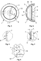
- Figure 1 an outer shell 1 for an acetabular implant 2 ( Fig. 9 ) a convex outside 3 and a concave inside 4.
- the inside 4 has a circular peripheral area 6, which is provided with a toothing 7.
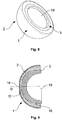
- an inner shell 5 for an inventive acetabular implant 2 has an articulated bearing surface 19 on its concave inside.
- the convex outside 15 is divided into different sections.
- the inner shell 5 shown has a conical region 16, on the edge region near the pole of which a latching element 17 is arranged.
- An extension 18 is attached to the pole of the inner shell 5. Both the conical region 16 and the extension 18 serve to prevent the inner shell 5 from tilting in the outer shell 1.
- the toothing 7 is mounted relatively far outside on the concave inside 4 of the outer shell 1.
- the radius r of the root circle 12 of the toothing 7 here is approximately 70% of the total radius R of the outer shell 1.
- FIG 5 is a schematic representation of the tooth profile according to Figure 4 .
- the root circle 12 and the tip circle 14 are shown in dashed lines in the tooth profile.
- the angle ⁇ enclosed by the tooth profile is also shown.
- the height h of the tooth profile is defined as the difference between the radius of the tip circle 14 and that of the root circle 12.
- Out Figure 7 is the design of the locking element 8 provided with a toothing 7. It can be seen that the toothing 7 has the width b, which in the present exemplary embodiment is identical to that of the latching element. It can also be seen that the toothing 7 here has a trapezoidal cross profile.
- FIG 8 An inventive acetabular implant 2 with outer shell 1 and inner shell 5 is shown in perspective.
- the joint bearing surface 19 can be seen in particular on the concave inside.
- Figure 9 shows a longitudinal section through said acetabular implant 2. It can be seen that the extension 18 at the pole of the inner shell 5 engages in the opening 13 provided in the outer shell 1.
- the common main axis (longitudinal central axis) of the outer shell and inner shell is designated SS.
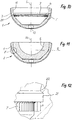
- FIGs 10 and 11 show a modified embodiment of an acetabular implant, in which the outer shell has a different inner contour.
- the toothing 7 is arranged in another area.
- the conical inlet area 11 on the inside 4 is followed by a likewise conical undercut 21, the configuration of which is shown in FIG Figure 12 is more clearly visible.
- the shoulder 22 between the undercut 21 and the conical area 11 forms the locking element of the outer shell, behind which a corresponding material shoulder 23 of the inner shell engages ( Figure 13 ).
- a circumferential cylindrical region to which the toothing 7 is attached. The toothing extends over the width b and thus not over the entire cylindrical area.
- the penetration depth e should not exceed 0.1 mm to 1 mm.
- the aim is to have the largest possible number of teeth 25 with a uniform spacing a from one another. These teeth have a height h, a difference remaining between e and h, so that a cavity 24 remains between adjacent tooth flanks 9.
- b is the width of the toothing, or more precisely the width of the penetration of the individual teeth into the material of the inner shell 5.
- the transmissible torque increases the greater the width b of the toothing for a given depth of penetration e.
- the press-in force is essentially determined by the penetration depth e.
- a torque specified by medical standards of, for example, greater than 12 Nm, which the inner shell must be able to transmit to the outer shell, the necessary dimensions of the toothing are determined depending on different shell sizes.
Description
Die vorliegende Erfindung betrifft ein Gelenkpfannenimplantat, insbesondere ein Hüftgelenkpfannenimplantat, umfassend eine Aussenschale und eine Innenschale.The present invention relates to an acetabular implant, in particular an acetabular implant, comprising an outer shell and an inner shell.
Beim Auftreten von Schädigungen an einer Gelenkpfanne, beispielsweise am Acetabulum, eines Patienten ist es gängige Praxis, eine künstliche Gelenkpfanne zu implantieren. Solche Gelenkpfannen sind oft zweiteilig aufgebaut, namentlich aus einer Aussenschale und einer Innenschale. Die Aussenschale dient dabei dem Einbetten der Gelenkpfanne in den Knochen. Die Innenschale, welche in die Aussenschale eingesetzt wird, bildet eine Lagerfläche für einen entsprechenden Gelenkkopf. Während Aussenschalen häufig aus einem Metall gefertigt sind, sind für Innenschalen sowohl Keramikmaterialien als auch Kunststoffe, insbesondere Polyäthylen, aber auch geeignete Metalle als Werkstoffe gebräuchlich.If damage to a joint socket, for example the acetabulum, of a patient occurs, it is common practice to implant an artificial joint socket. Such acetabular cups are often constructed in two parts, namely an outer shell and an inner shell. The outer shell is used to embed the socket in the bone. The inner shell, which is inserted into the outer shell, forms a bearing surface for a corresponding joint head. While outer shells are often made of a metal, both ceramic materials and plastics, in particular polyethylene, but also suitable metals are used as materials for inner shells.
Sowohl bei keramischen Innenschalen als auch bei solchen aus Kunststoff oder Metall ist es essentiell, dass eine Rotation gegenüber der Aussenschale verhindert wird. Dies liegt einerseits daran, dass es durch gegenseitige Reibung von nicht dazu vorgesehenen Teilen innerhalb der Gelenkschale rasch zu einer Beschädigung derselben kommt. Abgeriebene Partikel können zudem auf die Lagerflächen des Gelenkes gelangen und dort einen raschen Verschleiss verursachen, oder im schlimmsten Fall sogar in den Organismus des Patienten gelangen und diesen schädigen. Darüber hinaus muss insbesondere bei einseitig überhöhten Innenschalen sichergestellt werden, dass diese in einer bestimmten Winkelposition fixiert sind.With ceramic inner shells as well as those made of plastic or metal, it is essential that rotation with respect to the outer shell is prevented. On the one hand, this is due to the fact that mutual friction of parts not provided for this purpose quickly causes damage to the joint shell. Rubbed-off particles can also get onto the bearing surfaces of the joint and cause rapid wear there, or in the worst case even get into the patient's organism and damage it. In addition, it must be ensured in particular in the case of inner shells which are elevated on one side that they are fixed in a specific angular position.
Keramische oder metallische Innenschalen sind in der Regel konisch ausgeführt, wodurch sie nach Einsetzen in eine Aussenschale eine genügend grosse Haltekraft gegen das von einem Gelenckopf übertragene Drehmoment aufbringen. Innenschalen aus einem Kunststoffmaterial müssen dagegen zusätzlich gegen ein Verdrehen gesichert sein. Viele Aussenschalen weisen daher eine Verdrehsicherung in Form von Aussparungen in ihrem Randbereich (sogenannte "Scallops") auf, in die konvexe Strukturen der Innenschale eingreifen. Jedoch ist die Fertigung solcher Gelenkpfannen aufwändig und kostenintensiv.Ceramic or metallic inner shells are usually conical, which means that after they have been inserted into an outer shell, they exert a sufficiently large holding force against the torque transmitted by a head of the joint. Inner shells made of a plastic material, however, must be additionally secured against twisting. Many outer shells therefore have an anti-rotation device in the form of cutouts in their edge area (so-called "scallops"), which are engaged by convex structures of the inner shell. However, the production of such joint sockets is complex and cost-intensive.
In jüngerer Zeit wurden daher Aussenschalen entwickelt, auf deren konkaven Innenseite stachelförmige Eindringelemente angeordnet sind, die sich beim Einsetzen einer Innenschale aus Kunststoff in diese hineinbohren und so gegen ein Verdrehen sichern. Beispielsweise offenbart die
Derartige Verdrehsicherungen haben den Vorteil, dass zu deren Umsetzung keine konstruktiven Massnahmen an der Innenschale notwendig sind. Hingegen fallen bei der Fertigung der Aussenschale durch das Anbringen der Eindringelemente bedeutende Kosten an. Oft können die Eindringelemente nicht einstückig mit der Schale gefertigt werden, was ein Anbringen von Bohrungen und ein Setzen und Einpressen der Elemente erforderlich macht. Bestehen die Eindringelemente aus einem anderen Material als die Aussenschale, ist eine Deklaration desselben bei der Produktzulassung erforderlich, was diese zusätzlich erschwert. Um ein Einsetzen der Innenschale in die Aussenschale zu ermöglichen, müssen dornförmige Eindringelemente zudem zwangsläufig am Boden der Aussenschale angebracht sein, wodurch sie sich relativ nahe an der Längsmittelachse der Aussenschale befinden und dadurch nur ein geringes Drehmoment auf die Innenschale übertragen können.Such anti-rotation devices have the advantage that no structural measures are necessary on the inner shell to implement them. On the other hand, significant costs are incurred in the manufacture of the outer shell by attaching the penetration elements. Often the penetration elements cannot be made in one piece with the shell, which means drilling holes and setting and pressing in the elements. If the penetration elements are made of a different material than the outer shell, a declaration of the same is necessary when the product is approved, which makes this even more difficult. In order to enable the inner shell to be inserted into the outer shell, mandrel-shaped penetration elements must also be attached to the bottom of the outer shell, as a result of which they are relatively close to the longitudinal central axis of the outer shell and can therefore transmit only a small torque to the inner shell.
Durch die
Eine ähnliche Lösung ist in der
Ein Nachteil der bisher bekannten Rotationshemmung durch Verzahnung besteht darin, dass hohe Einpresskräfte zum Einsetzen der Innenschale erforderlich sind und dass die Gefahr besteht, dass das Material der Innenschale beschädigt wird, wobei eine nicht erwünschte Zerspanung stattfindet, bei welcher möglicherweise Partikel der Innenschale abgetragen werden. Die Zähne haben dabei eine ungünstige Konfiguration oder sie sind überdimensioniert oder zu zahlreich angeordnet, um einem vorgegebenen Solldrehmoment zwischen den beiden Schalenteilen zu widerstehen. Dabei ist ausserdem noch zu berücksichtigen, dass die zum Einsetzen der Innenschale erforderliche Einpresskraft begrenzt ist, wenn der Chirurg die Innenschale in situ einschlagen oder einpressen muss.A disadvantage of the previously known rotation inhibition by toothing is that high press-in forces are required to insert the inner shell and that there is a risk that the material of the inner shell is damaged, with undesired machining taking place, in which particles of the inner shell may be removed. The teeth have an unfavorable configuration or they are oversized or too numerous to withstand a predetermined target torque between the two shell parts. It should also be taken into account that the press-in force required to insert the inner shell is limited, when the surgeon has to drive in or press in the inner shell.
Es ist daher eine Aufgabe der vorliegenden Erfindung, die oben genannten Nachteile im Stand der Technik zu überwinden. Insbesondere ist es eine Aufgabe der Erfindung, ein Gelenkpfannenimplantat mit einer möglichst zuverlässigen und konstruktiv einfachen Verdrehsicherung bereitzustellen. Eine derartige Verdrehsicherung soll leicht in bestehende Implantatsysteme implementierbar sein. Zudem soll deren Implementierung kostengünstig sein und dem behandelnden Chirurgen eine leichte Handhabung des Implantates sowie eine stufenlose axiale Winkeleinstellung bezüglich der Schalenachse ermöglichen.It is therefore an object of the present invention to overcome the above-mentioned disadvantages in the prior art. In particular, it is an object of the invention to provide an acetabular implant with the most reliable and structurally simple anti-rotation device possible. Such an anti-rotation device should be easy to implement in existing implant systems. In addition, their implementation should be inexpensive and allow the treating surgeon easy handling of the implant and a continuous axial angle adjustment with respect to the shell axis.
Weiter ist es eine Aufgabe der vorliegenden Erfindung, die Verzahnung derart auszubilden, dass das weichere Material der Innenschale nicht beschädigt wird und dass bei möglichst geringer Einpresskraft ein maximales Drehmoment übertragbar ist.A further object of the present invention is to design the toothing in such a way that the softer material of the inner shell is not damaged and that a maximum torque can be transmitted with the lowest possible press-in force.
Diese Aufgaben werden durch ein Gelenkpfannenimplantat mit den Merkmalen in Anspruch 1 gelöst. Dieses Gelenkpfannenimplantat umfasst eine Aussenschale mit einer konvexen Aussenseite und einer konkaven Innenseite, welch letztere in einem kreisförmig umlaufenden Bereich eine Verzahnung aufweist. Die Flanken der Verzahnung sind parallel zur Längsmittelachse der Aussenschale ausgerichtet und das Zahnprofil weist eine Zahnhöhe auf, welche definiert ist als Differenz zwischen dem Radius des Kopfkreises und dem Radius des Fusskreises der Verzahnung. Das Gelenkpfannenimplantat umfasst ferner eine in die Aussenschale eingesetzte Innenschale, wobei die Härte der Aussenschale grösser ist als diejenige der Innenschale und wobei der mit der Verzahnung in Kontakt kommende Bereich der Innenschale relativ zum Kopfkreis der Verzahnung ein Übermass hat. Dadurch ist eine Hemmung der relativen Rotationsfähigkeit der beiden Schalen durch Verdrängen des Materials der Innenschale durch die Verzahnung erzielbar.These tasks are solved by an acetabular implant with the features in
Es ist besonders vorteilhaft, wenn sich die Verzahnung durchgehend, vorzugsweise mit gleichmässiger Teilung, über den kreisförmig umlaufenden Bereich an der Aussenschale erstreckt. Unter gleichmässiger Teilung wird dabei ein gleicher Abstand zwischen den einzelnen Zähnen verstanden und zwar derart, dass die Verzahnung einer sich über 360° erstreckenden Innenverzahnung entspricht.It is particularly advantageous if the toothing extends continuously, preferably with a uniform division, over the circular area on the outer shell. Uniform pitch is understood to mean an equal distance between the individual teeth, in such a way that the toothing corresponds to an internal toothing that extends over 360 °.
Vorteilhaft weisen die Aussenschale und die Innenschale korrespondierende axiale Rastelemente auf, an denen sie bezogen auf die gemeinsame Längsmittelachse miteinander verrastet sind. Eine derartige Verrastung ist erforderlich, weil mit einer Innenschale aus Kunststoffmaterial in axialer Richtung keine Selbsthemmung beispielsweise durch eine Konusverbindung erzielbar ist.The outer shell and the inner shell advantageously have corresponding axial latching elements, on which they are latched together with respect to the common longitudinal central axis. Such latching is necessary because with an inner shell made of plastic material, no self-locking can be achieved in the axial direction, for example by a cone connection.
Besonders vorteilhaft ist der umlaufende Bereich mit der Verzahnung in einem zylindrischen Abschnitt der konkaven Innenseite der Aussenschale angeordnet, der sich bezogen auf die gemeinsame Längsmittelachse an die korrespondierenden Rastelemente anschliesst. Durch die unmittelbare Nachbarschaft der Rastelemente zu der Verzahnung können produktionstechnische Vorteile erzielt werden. Dabei spielt es keine Rolle, ob bezogen auf die gemeinsame Längsmittelachse vom Äquator der Schale zum Scheitelpunkt gesehen zuerst die Verzahnung oder die Rastelemente angeordnet sind. Es wäre grundsätzlich auch möglich, die Verzahnung und die Rastelemente bezogen auf die gemeinsame Längsmittelachse mit einem Abstand zueinander in der Aussenschale anzuordnen. Besonders vorteilhaft ist es jedoch, wenn der umlaufende Bereich mit der Verzahnung bezogen auf die Längsmittelachse näher am Äquator der Aussenschale liegt als an deren Scheitelpunkt. In diesem Äquator nahen Bereich ist der Innendurchmesser der Aussenschale am grössten, womit auch ein maximaler Durchmesser der Verzahnung erreicht werden kann. Dadurch kann sowohl die Anzahl Zähne vergrössert, als auch der Abstand der Zähne zur Drehachse vergrössert und dadurch das grösstmögliche Drehmoment übertragen werden.The circumferential region with the toothing is particularly advantageously arranged in a cylindrical section of the concave inside of the outer shell, which connects to the corresponding latching elements with respect to the common longitudinal central axis. Production-related advantages can be achieved through the immediate vicinity of the locking elements to the toothing. It does not matter whether the toothing or the locking elements are arranged first with respect to the common longitudinal central axis from the equator of the shell to the apex. In principle, it would also be possible to arrange the toothing and the latching elements in the outer shell at a distance from one another in relation to the common longitudinal central axis. However, it is particularly advantageous if the circumferential area with the toothing is closer to the equator of the outer shell with respect to the longitudinal central axis than to the apex of the latter. In this equator In the vicinity, the inside diameter of the outer shell is the largest, which means that a maximum diameter of the toothing can also be achieved. This allows both the number of teeth to be increased and the distance between the teeth and the axis of rotation to be increased, thereby transmitting the greatest possible torque.
Weiter ist es besonders vorteilhaft, wenn die Verzahnung bezogen auf die Längsmittelachse eine Breite zwischen 0,5 mm bis 5 mm bevorzugt zwischen 0,8 mm bis 1,6 mm aufweist. Mit der Breite der Verzahnung lässt sich in Abhängigkeit von deren Eindringtiefe in die Innenschale das übertragbare Drehmoment bestimmen. Je breiter die Verzahnung und damit der maximal mögliche Eingriff bezogen auf die Längsmittelachse ausfällt, desto höher ist das übertragbare Drehmoment an der Verzahnung.Furthermore, it is particularly advantageous if the toothing has a width between 0.5 mm and 5 mm, preferably between 0.8 mm and 1.6 mm, based on the longitudinal central axis. The torque that can be transmitted can be determined with the width of the toothing, depending on its depth of penetration into the inner shell. The wider the toothing and thus the maximum possible engagement in relation to the longitudinal center axis, the higher the torque that can be transmitted to the toothing.
Weiter ist es besonders vorteilhaft, wenn die Verzahnung mit einer Zahneindringtiefe in das Material der Innenschale eindringt, welche zwischen 0,1 mm bis 1 mm, bevorzugt zwischen 0,15 mm bis 0,3 mm liegt. Es hat sich überraschend gezeigt, dass die Einpresskraft im Wesentlichen durch die Zahneindringtiefe bestimmt wird und nur unbedeutend durch die vorstehend erwähnte Zahnbreite. Je höher die Eindringtiefe ist, und je mehr Zähne die Verzahnung aufweist, desto höher ist die erforderliche Einpresskraft. Die Eindringtiefe sollte jedoch so klein wie möglich ausfallen, damit keine Beschädigung oder Abspannung am Material der Innenschale stattfindet. Daraus ergibt sich die Lehre, dass die Anzahl Zähne möglichst gross und deren Eindringtiefe möglichst klein gehalten werden muss, damit die Einpresskraft tief gehalten werden kann. Das übertragbare Drehmoment kann danach mit Hilfe der Zahnbreite definiert werden.Furthermore, it is particularly advantageous if the toothing penetrates into the material of the inner shell with a tooth penetration depth which is between 0.1 mm and 1 mm, preferably between 0.15 mm and 0.3 mm. It has surprisingly been found that the press-in force is essentially determined by the tooth penetration depth and only insignificantly by the tooth width mentioned above. The greater the depth of penetration, and the more teeth the teeth have, the higher the press-in force required. However, the depth of penetration should be as small as possible so that there is no damage or bracing to the material of the inner shell. This leads to the teaching that the number of teeth must be as large as possible and their penetration depth must be kept as small as possible so that the press-in force can be kept low. The transferable torque can then be defined using the tooth width.
Dabei hat es sich als besonders vorteilhaft erwiesen, wenn die Gesamtzahl Zähne der Verzahnung und die Breite der Zähne bezogen auf die Längsmittelachse derart gewählt werden, dass die Hemmung der Rotationsfähigkeit ein vorgegebenes Solldrehmoment immer übertrifft. Das minimal übertragbare Drehmoment wird durch einschlägige Medizinalnormen vorgegeben und muss in jedem Fall eingehalten werden. Bei einer vorgegebenen Eindringtiefe zwischen 0,1 mm und 1 mm und in Abhängigkeit von der Schalengrösse bzw. vom Durchmesser der Verzahnung lassen sich so die Zähnezahl und deren Breite optimieren.It has proven to be particularly advantageous if the total number of teeth of the toothing and the width of the teeth are selected in relation to the longitudinal central axis in such a way that the inhibition of the ability to rotate always exceeds a predetermined target torque. The minimum torque that can be transmitted is specified by the relevant medical standards and must always be observed. With a given penetration depth between 0.1 mm and 1 mm and depending on the shell size or the diameter of the toothing, the number of teeth and their width can be optimized.
Die einzelnen Zähne der Verzahnung können einen Winkel von vorzugsweise 45° bis 100° einschliessen. Aus fabrikationstechnischen Gründen wird sich an der Spitze jeweils immer eine geringfügige Abflachung oder Rundung ergeben. Ein Winkel von mehr als 100° führt zu entsprechend breiten Zähnen am Zahnfuss, womit die Gesamtzahl der Zähne reduziert wird, die am umlaufenden Bereich untergebracht werden können.The individual teeth of the toothing can enclose an angle of preferably 45 ° to 100 °. For manufacturing reasons, there will always be a slight flattening or rounding at the top. An angle of more than 100 ° leads to correspondingly wide teeth on the tooth base, which reduces the total number of teeth that can be accommodated in the surrounding area.
Es hat sich ferner als besonders vorteilhaft erwiesen, wenn die Seitenflanken der Zähne als ebene Flächen ausgebildet sind. Damit ist gewährleistet, dass möglichst die gesamte Zahnflanke an der Innenschale anliegt.It has also proven to be particularly advantageous if the side flanks of the teeth are designed as flat surfaces. This ensures that the entire tooth flank is in contact with the inner shell if possible.
Weitere Vorteile können erreicht werden, wenn zwischen den Seitenflanken benachbarter Zähne und der in die Verzahnung eingesetzten Innenschale ein Hohlraum verbleibt. Dieser ermöglicht bei Innenschalen aus weichem Material eine weitere Ausdehnung, insbesondere einen Materialfluss in den Hohlraum unter Last. Auf diese Weise können schädliche Materialspannungen, welche zu einer erhöhten Einpresskraft oder einer unerwünschten Ausdehnung des Materials gegen die Längsmittelachse hin, vermieden werden.Further advantages can be achieved if a cavity remains between the side flanks of adjacent teeth and the inner shell inserted into the toothing. With inner shells made of soft material, this enables further expansion, in particular a flow of material into the cavity under load. In this way, harmful material tensions, which lead to an increased pressing force or an undesirable expansion of the material towards the longitudinal central axis, can be avoided.
In bestimmten Fällen kann sich die Verzahnung auch nur teilweise über den kreisförmig umlaufenden Bereich erstrecken. Eine derart teilweise unterbrochene Verzahnung hat den Vorteil, dass die Einpresskraft reduziert werden kann und zwar bei gleichbleibender Eindringtiefe.In certain cases, the toothing can also only partially extend over the circular circumferential area. A toothing that is partially interrupted in this way has the advantage that the press-in force can be reduced and that with a constant penetration depth.
Besonders vorteilhaft besteht die Innenschale aus einem Kunststoffmaterial, insbesondere aus einem Polyethylen mit einer Shore-Härte D zwischen 50 und 85. Ein Kunststoffmaterial mit dieser Härte weist optimale Materialeigenschaften auf, damit die Innenschale zerstörungsfrei in die Verzahnung gepresst werden kann.The inner shell particularly advantageously consists of a plastic material, in particular a polyethylene with a Shore hardness D between 50 and 85. A plastic material with this hardness has optimal material properties so that the inner shell can be pressed into the toothing without being destroyed.
Vorzugsweise ist mittels der Verzahnung ein Drehmoment von mehr als 10 Nm (Newtonmeter), vorzugsweise von mehr als 12 Nm übertragbar. Dabei handelt sich um das vorstehend erwähnte SollDrehmoment, das durch einschlägige Medizinalnormen vorgegeben ist. So beispielsweise durch das "Guidance document for testing acetabular cup prostheses" der US amerikanischen Federal Drug Administration (FDA). Die angegeben Werte enthalten einen Sicherheitsfaktor im Verhältnis zu den tatsächlich unter Last auftretenden Drehmomenten, die durch einen Patienten ausgelöst werden können.A torque of more than 10 Nm (Newton meters), preferably of more than 12 Nm, can preferably be transmitted by means of the toothing. This is the target torque mentioned above, which is specified by relevant medical standards. For example, through the "Guidance document for testing acetabular cup prostheses" of the US Federal Drug Administration (FDA). The values given contain a safety factor in relation to the torques actually occurring under load that can be triggered by a patient.
Die Aussenschale für das Gelenkpfannenimplantat, insbesondere für ein Hüftgelenkpfannenimplantat, hat eine konvexe Aussenseite und eine konkave Innenseite zur Aufnahme einer Innenschale. Die konkave Innenseite weist in einem insbesondere kreisförmig umlaufenden Bereich zumindest teilweise eine Verzahnung auf. Durch die Verzahnung ist beim Einsetzen der Innenschale in die Aussenschale eine Hemmung der relativen Rotationsfähigkeit der beiden Schalen bezüglich der gemeinsamen Hauptachse erzielbar.The outer shell for the acetabular implant, in particular for an acetabular implant, has a convex outside and a concave inside for receiving an inner shell. The concave inside has, at least in part, a toothing in a particularly circular area. The teeth can be used to inhibit the relative rotation ability of the two shells with respect to the common main axis when inserting the inner shell into the outer shell.
Durch das Anbringen einer Verzahnung an der konkaven Innenseite der Aussenschale wird eine besonders zuverlässige Verdrehsicherung geschaffen. Die Verzahnung lässt sich leicht an der Aussenschale anbringen und kann den jeweils vorliegenden Erfordernissen angepasst werden.Attaching teeth on the concave inside of the outer shell creates a particularly reliable anti-twist device. The teeth can be easily attached to the outer shell and can be adapted to the respective requirements.
Bevorzugt wird die Verzahnung durch ein spanabhebendes Verfahren wie beispielsweise Fräsen oder Stossen hergestellt. In bestimmten Fällen ist aber auch die Herstellung durch einen Umformungsprozess oder durch Erodieren denkbar.The toothing is preferably produced by a machining process such as milling or shaping. In certain cases, however, production by a forming process or by eroding is also conceivable.
Die Verzahnung kann sich durchgehend über den insbesondere kreisförmig umlaufenden Bereich erstrecken. Dadurch ist ein vergleichsweise hohes Drehmoment von der Aussenschale auf die Innenschale übertragbar. Allerdings ist auch eine vergleichsweise hohe Einpresskraft zum Einsetzen der Innenschale in die Aussenschale erforderlich. Daher kann sich die Verzahnung auch mit Unterbrüchen über den insbesondere kreisförmig umlaufenden Bereich erstrecken. Dadurch kann eine Reduktion der zum Einsetzen der Innenschale in die Aussenschale erforderlichen Einpresskraft erzielt werden, was allerdings auf Kosten des übertragbaren Drehmomentes geht. Durch ein gut abgestimmtes Verhältnis zwischen den Bereichen mit Verzahnung und den Unterbrüchen kann die Verdrehsicherung so ausgelegt werden, dass sich bei minimaler Einpresskraft ein akzeptables Drehmoment von der Aussenschale auf die Innenschale übertragen lässt.The toothing can extend continuously over the area, which in particular is circular. As a result, a comparatively high torque can be transferred from the outer shell to the inner shell. However, a comparatively high press-in force is also required to insert the inner shell into the outer shell. Therefore, the toothing can also extend with interruptions over the particularly circular area. This enables a reduction in the press-in force required to insert the inner shell into the outer shell, but this is at the expense of the transmissible torque. Thanks to a well-coordinated relationship between the areas with toothing and the interruptions, the anti-rotation device can be designed in such a way that an acceptable torque can be transferred from the outer shell to the inner shell with minimal insertion force.
Der Radius des Fusskreises der Verzahnung kann mindestens 50%, vorzugsweise mindestens 60%, bevorzugterweise mindestens 70% des Gesamtradius der Aussenschale betragen. Je mehr sich der Radius des Fusskreises dem Gesamtradius der Aussenschale annähert, desto grösser wird das übertragbare Drehmoment. Unter Fusskreis wird derjenige Kreis verstanden, auf dem die tiefsten Stellen der Verzahnung liegen.The radius of the root circle of the toothing can be at least 50%, preferably at least 60%, preferably at least 70% of the total radius of the outer shell. The closer the radius of the root circle to the total radius of the outer shell, the greater the torque that can be transmitted. Under foot circle the circle is understood on which the lowest points of the toothing lie.
Die Aussenschale kann zumindest ein Rastelement zum axialen Einrasten der Innenschale in der Aussenschale aufweisen. Im Zusammenhang mit derartigen Rastelementen wird im Fachjargon auch von so genannten Schnappverbindungen gesprochen. Eine derartige Schnappverbindung erlaubt es insbesondere bei Gelenkpfannenimplantaten mit Innenschalen aus Kunststoff, dass die Innenschale beim Einsetzen in die Aussenschale in diese einschnappt bzw. einrastet und dadurch festgehalten wird. Eine Kombination einer derartigen Schnappverbindung mit einer erfindungsgemässen Verdrehsicherung ermöglicht es, eine Innenschale derart in der Aussenschale zu verankern, dass sie sowohl gegen ein Verdrehen als auch gegen ein Hinausfallen gesichert ist.The outer shell can have at least one latching element for axially latching the inner shell in the outer shell. In connection with such locking elements, so-called snap connections are also spoken in technical jargon. Such a snap connection makes it possible, particularly in the case of joint socket implants with inner shells made of plastic, that the inner shell snaps or snaps into the outer shell when it is inserted and is thereby held in place. A combination of such a snap connection with an anti-twist device according to the invention makes it possible to anchor an inner shell in the outer shell in such a way that it is secured both against twisting and against falling out.
Der insbesondere kreisförmig umlaufende Bereich mit der Verzahnung kann anschliessend an einem axialen Rastelement der Aussenschale angeordnet sein. Durch die Kombination von Rastelement und Verzahnung kann ein kompaktes Strukturelement auf der konkaven Innenseite der Aussenschale geschaffen werden, welches die Innenschale gleichzeitig gegen ein Verdrehen und ein Hinausfallen sichert.The particularly circular area with the toothing can then be arranged on an axial locking element of the outer shell. The combination of locking element and toothing can be used to create a compact structural element on the concave inside of the outer shell, which simultaneously secures the inner shell against twisting and falling out.
Die Verzahnung kann ein Zahnprofil mit einer Höhe aufweisen, welche mindestens das 1,5 bis 2-fache der gewünschten Eindringtiefe hat. Durch dieses Verhältnis ist sichergestellt, dass das beim Einpressen verdrängte Material der Innenschale Platz findet und damit nicht zu einer Erhöhung der Einpresskraft führt.The toothing can have a tooth profile with a height which is at least 1.5 to 2 times the desired depth of penetration. This ratio ensures that the material of the inner shell displaced during the press-in process can be accommodated and therefore does not lead to an increase in the press-in force.
Das Zahnprofil der Verzahnung kann dreieckig oder trapezförmig sein und einen Winkel α von 30° bis 120°, vorzugsweise von 45° bis 110°, bevorzugterweise von 60° bis 100°, einschliessen. Derartige Geometrien lassen sich gut an der konkaven Innenseite der Aussenschale anbringen. Sie weisen beim Eindringen der Verzahnung in die Aussenseite der Innenschale eine günstige Charakteristik auf. Zudem verhindert ein derartiges Zahnprofil in der Regel auf besonders zuverlässige Weise eine relative Rotationsbewegung zwischen dem Einsatz und der Aussenschale.The tooth profile of the toothing can be triangular or trapezoidal and include an angle α of 30 ° to 120 °, preferably 45 ° to 110 °, preferably 60 ° to 100 °. Such Geometries can be easily attached to the concave inside of the outer shell. They have a favorable characteristic when the teeth penetrate into the outside of the inner shell. In addition, such a tooth profile generally prevents a relative rotational movement between the insert and the outer shell in a particularly reliable manner.
Die Flanken der Verzahnung können parallel zur Längsmittelachse der Aussenschale ausgerichtet sein. Diese Ausgestaltung ermöglicht es, dass der mit der Verzahnung in Kontakt kommende Bereich der Innenschale zylindrisch ausgebildet sein kann.The flanks of the toothing can be aligned parallel to the longitudinal center axis of the outer shell. This configuration enables the region of the inner shell that comes into contact with the toothing to be cylindrical.
Die Verzahnung kann bezogen auf die Axialrichtung eine Breite von 10 mm bis 0.1 mm, vorzugsweise von 5 mm bis 0.5 mm, bevorzugterweise 1.6 mm bis 0.8 mm aufweisen.The toothing can have a width of 10 mm to 0.1 mm, preferably 5 mm to 0.5 mm, preferably 1.6 mm to 0.8 mm, based on the axial direction.
Der umlaufende Bereich mit der Verzahnung kann in einem zylindrischen Abschnitt der konkaven Innenseite der Aussenschale angeordnet sein, der an einen konischen Abschnitt anschliesst. Durch das Anbringen eines konischen Abschnitts an der konkaven Innenseite der Aussenschale kann ein Verkippen der Innenschale während des Montierens im Operationssaal wirkungsvoll vermieden werden.The circumferential area with the toothing can be arranged in a cylindrical section of the concave inside of the outer shell, which adjoins a conical section. By attaching a conical section to the concave inside of the outer shell, tilting of the inner shell can be effectively avoided during assembly in the operating room.
Derartige Aussenschalen sind je nach Ausführung sowohl als Erstersatz für ein Kugelgelenk als auch als Revisionsschalen geeignet.Depending on the design, such outer shells are suitable both as an initial replacement for a ball joint and as revision shells.
Die vorliegende Erfindung betrifft ein Gelenkpfannenimplantat umfassend eine Aussenschale der oben beschriebenen Art sowie eine in die Aussenschale einsetzbare Innenschale. Die Härte der Aussenschale ist dabei grösser als diejenige der Innenschale. Dadurch ist bei Einsetzen der Innenschale in die Aussenschale eine Hemmung der relativen Rotationsfähigkeit der beiden Schalen durch Verdrängen des Materials der Innenschale durch die Verzahnung der Aussenschale erzielbar.The present invention relates to an acetabular implant comprising an outer shell of the type described above and an inner shell which can be inserted into the outer shell. The hardness of the outer shell is greater than that of the inner shell. This is when inserting the inner shell into the outer shell an inhibition of the relative rotational ability of the two shells can be achieved by displacing the material of the inner shell by the teeth of the outer shell.
Bei einem derartigen Gelenkpfannenimplantat kann die Aussenschale aus Titan oder aus einer Titan-, Stahl-, Kobalt- oder Zirkon-Basislegierung gefertigt sein. Allerdings kann die Aussenschale auch aus einem Keramikmaterial gefertigt sein. Bei diesen Materialien handelt es sich um bei der Implantatherstellung gängige Werkstoffe. Sie zeichnen sich durch eine hervorragende Biokompatibilität aus und ermöglichen eine zuverlässige Verankerung der Aussenschale in einem Knochen eines Patienten.With such an acetabular implant, the outer shell can be made from titanium or from a titanium, steel, cobalt or zirconium-based alloy. However, the outer shell can also be made from a ceramic material. These materials are common materials used in implant manufacture. They are characterized by excellent biocompatibility and enable the outer shell to be reliably anchored in a patient's bone.
Die Innenschale kann aus Polyethylen, insbesondere aus einem UHMWPE, oder aus einem UXPE, einem PEEK oder einem PEAK gefertigt sein. Unter UHMWPE wird im Zusammenhang mit der vorliegenden Anmeldung ein Polyethylen mit ultrahoher molekularer Masse verstanden. Bei den genannten Materialien handelt es sich um gängige Werkstoffe für die Herstellung von Laufflächen bei künstlichen Gelenken. Sie zeichnen sich durch einen besonders geringen Gleitwiderstand, eine lange Lebensdauer und eine gute Patientenverträglichkeit aus.The inner shell can be made from polyethylene, in particular from a UHMWPE, or from a UXPE, a PEEK or a PEAK. In the context of the present application, UHMWPE is understood to mean an ultra-high molecular weight polyethylene. The materials mentioned are common materials for the production of treads in artificial joints. They are characterized by a particularly low sliding resistance, a long service life and good patient tolerance.
Allerdings ist es auch möglich, dass die Innenschale eine Verbundstruktur bestehend aus einem der oben genannten Kunststoffmaterialien und einem Metall oder einem Keramikmaterial ist. Bei einer derartigen Verbundstruktur ist die der Aussenschale zugewandte konvexe Aussenseite der Innenschale aus einem Kunststoffmaterial gefertigt, während die Lagerfläche des Gelenkes aus Metall oder einem Keramikmaterial ist. Derartige Verbundstrukturen lassen sich hervorragend in eine erfindungsgemässe Aussenschale einpressen und im Vergleich zu einer reinen Kunststoffinnenschale ein besseres Gleit- und Abriebverhalten der Lagerfläche auf.However, it is also possible for the inner shell to be a composite structure consisting of one of the above-mentioned plastic materials and a metal or a ceramic material. With such a composite structure, the convex outer side of the inner shell facing the outer shell is made of a plastic material, while the bearing surface of the joint is made of metal or a ceramic material. Composite structures of this type can be pressed into an outer shell according to the invention and, compared to a pure plastic inner shell, have better sliding and abrasion behavior of the bearing surface.
Weitere Vorteile und Einzelmerkmale der Erfindung ergeben sich aus der nachfolgenden Beschreibung eines Ausführungsbeispiels und aus den Zeichnungen.Further advantages and individual features of the invention result from the following description of an exemplary embodiment and from the drawings.
Es zeigen schematisch:
- Figur 1:
- Perspektivische Darstellung einer Aussenschale für ein Gelenkpfannenimplantat;
- Figur 2:
- Perspektivische Darstellung einer Innenschale zur Verwendung mit einer Aussenschale;
- Figur 3:
- Draufsicht auf eine Aussenschale;
- Figur 4:
- Vergrösserung des Teilbereichs
B gemäss Figur 3 ; - Figur 5:
- Schematische Vergrösserung des Teilbereichs
D gemäss Figur 4 ; - Figur 6:
- Schnittansicht einer Aussenschale durch die Schnittebene
A gemäss Figur 3 ; - Figur 7:
- Vergrösserung des Teilbereichs
C gemäss Figur 6 ; - Figur 8:
- Perspektivische Darstellung einer Innenschale eingesetzt in eine Aussenschale;
- Figur 9:
- Schnittansicht einer Innenschale eingesetzt in eine Aussenschale;
- Figur 10:
- Schnittansicht eines alternativen Ausführungsbeispiels einer Aussenschale;
- Figur 11:
- Schnittansicht eines alternativen Ausführungsbeispiels einen Gelenkpfannenimplantats unter Verwendung der Aussenschale gemäss
Figur 10 ; - Figur 12:
- Vergrösserung des Teilbereichs E gemäss
Figur 10 ; - Figur 13:
- Vergrösserung des Teilbereichs
F gemäss Figur 11 ; - Figur 14:
- Vergrösserung des Teilschnitts durch die Ebene
G gemäss Figur 11 und; - Figur 15:
- Eine perspektivische und schematische Darstellung des Eingriffs von zwei Zähnen einer Verzahnung in das Material der Innenschale.
- Figure 1:
- Perspective representation of an outer shell for an acetabular implant;
- Figure 2:
- Perspective view of an inner shell for use with an outer shell;
- Figure 3:
- Top view of an outer shell;
- Figure 4:
- Enlargement of subarea B according to
Figure 3 ; - Figure 5:
- Schematic enlargement of section D according to
Figure 4 ; - Figure 6:
- Sectional view of an outer shell through the section plane A according to
Figure 3 ; - Figure 7:
- Enlargement of subarea C according to
Figure 6 ; - Figure 8:
- Perspective view of an inner shell inserted into an outer shell;
- Figure 9:
- Sectional view of an inner shell inserted into an outer shell;
- Figure 10:
- Sectional view of an alternative embodiment of an outer shell;
- Figure 11:
- Sectional view of an alternative embodiment of a socket implant using the outer shell according to
Figure 10 ; - Figure 12:
- Enlargement of subarea E according to
Figure 10 ; - Figure 13:
- Enlargement of subarea F according to
Figure 11 ; - Figure 14:
- Enlargement of the partial section through plane G according to
Figure 11 and; - Figure 15:
- A perspective and schematic representation of the engagement of two teeth of a toothing in the material of the inner shell.
Wie aus
Wie
Aus
Aus
Bei
Durch die Schnittansicht gemäss
Aus
In
Die
In
Claims (11)
- Joint socket implant (2), in particular an acetabular implant, comprising an outer shell (1) with a convex outer face (3) and a concave inner face (4), which has a toothing system (7) in a circular circumferential region (6), wherein the flanks (9) of the toothing system are oriented parallel to a longitudinal central axis (S) of the outer shell (1), and wherein the tooth profile has a tooth height (h) defined as the difference between the radius of the tip circle and the radius of the root circle of the toothing system, and an inner shell (5) inserted into the outer shell, wherein the hardness of the outer shell is greater than that of the inner shell, and wherein the region of the inner shell coming into contact with the toothing system has an oversize relative to the tip circle of the toothing system, such that an inhibition of the rotatability of the two shells relative to each other can be achieved by the material of the inner shell being displaced by the toothing system, characterized in that the toothing system (7) extends continuously, with uniform pitch, about the circular circumferential region (6), such that the toothing system (7) corresponds to an inner toothing extending through 360°, wherein the toothing system (7) penetrates into the material of the inner shell (5) with a tooth penetration depth (e) of between 0.1 and 1.0 mm, wherein a hollow space (24) remains between the side flanks of adjacent teeth and the inner shell (5) inserted into the toothing system (7), and the total number of teeth of the toothing system (7) and the width (b) of the teeth relative to the longitudinal central axis (S) are chosen in such a way that the inhibition of the rotatability exceeds a predefined setpoint torque of 10 Nm.
- Joint socket implant according to Claim 1, wherein the outer shell (1) is produced from titanium or from a titanium-based, steel-based, cobalt-based or zirconium-based alloy.
- Joint socket implant according to Claim 1 or 2, wherein the inner shell (5) is produced from a polyethylene, in particular from a UHMWPE or from a UXPE, or from a PEEK or from a PEAK.
- Joint socket implant according to one of Claims 1 to 3, wherein the outer shell (1) and the inner shell (5) have corresponding axial locking elements (8, 17), at which they are locked onto each other relative to the common longitudinal central axis (S).
- Joint socket implant according to Claim 4, wherein the circumferential region with the toothing system is arranged in a cylindrical portion of the concave inner face (4) of the outer shell (1) adjacent to the corresponding locking elements (8, 17), relative to the common longitudinal central axis (S) .
- Joint socket implant according to one of Claims 1 to 5, wherein the tooth penetration depth (e) is between 0.15 mm and 0.3 mm.
- Joint socket implant according to one of Claims 1 to 6, wherein the individual teeth of the toothing system enclose an angle of preferably 45° to 100°.
- Joint socket implant according to Claim 7, wherein the side flanks (9) of the teeth are plane surfaces.
- Joint socket implant according to one of Claims 1 to 8, wherein, relative to the central longitudinal axis (S), the circumferential region with the toothing system (7) lies closer to the equator of the outer shell (1) than to the pole.
- Joint socket implant according to one of Claims 1 to 9, wherein the inner shell (5) is made of a plastic material, in particular of a polyethylene, with a Shore hardness D of between 50 and 85.
- Joint socket implant according to one of Claims 1 to 10, wherein a torque of more than 12 Nm can be transmitted by means of the toothing system.
Applications Claiming Priority (2)
| Application Number | Priority Date | Filing Date | Title |
|---|---|---|---|
| EP15195856 | 2015-11-23 | ||
| PCT/EP2016/078390 WO2017089332A1 (en) | 2015-11-23 | 2016-11-22 | Joint socket implant |
Publications (2)
| Publication Number | Publication Date |
|---|---|
| EP3380047A1 EP3380047A1 (en) | 2018-10-03 |
| EP3380047B1 true EP3380047B1 (en) | 2020-07-08 |
Family
ID=54697489
Family Applications (1)
| Application Number | Title | Priority Date | Filing Date |
|---|---|---|---|
| EP16804722.3A Active EP3380047B1 (en) | 2015-11-23 | 2016-11-22 | Acetabular implant |
Country Status (4)
| Country | Link |
|---|---|
| US (1) | US10945849B2 (en) |
| EP (1) | EP3380047B1 (en) |
| CN (1) | CN108289740A (en) |
| WO (1) | WO2017089332A1 (en) |
Families Citing this family (1)
| Publication number | Priority date | Publication date | Assignee | Title |
|---|---|---|---|---|
| CN113749827B (en) * | 2021-11-05 | 2022-04-19 | 北京爱康宜诚医疗器材有限公司 | Acetabular prosthesis |
Family Cites Families (8)
| Publication number | Priority date | Publication date | Assignee | Title |
|---|---|---|---|---|
| US5092897A (en) * | 1990-03-15 | 1992-03-03 | Forte Mark R | Implantable acetabular prosthetic hip joint with universal adjustability |
| ATE189377T1 (en) | 1993-12-20 | 2000-02-15 | Sulzer Orthopaedie Ag | ARTIFICIAL HIP JOINT |
| US5800555A (en) | 1997-04-24 | 1998-09-01 | Depuy Orthopaedics, Inc. | Acetabular cup bearing liner |
| DE10106863C2 (en) * | 2001-02-14 | 2003-04-03 | Hans Ulrich Staeubli | Implantable cup for hip joint endoprostheses |
| EP1420724A1 (en) * | 2001-08-20 | 2004-05-26 | Biomet Merck GmbH | Artificial hip joint acetabulum |
| FR2829687B1 (en) * | 2001-09-20 | 2003-12-05 | Smile Fit | HIP PROTHETIC COTYLE |
| DE102006017473A1 (en) * | 2006-04-13 | 2007-10-18 | Plus Orthopedics Ag | Articular socket, in particular for a hip endoprosthesis |
| FR2936145B1 (en) * | 2008-09-25 | 2011-11-11 | Sem Sa | COTYL FOR HIP JOINT PROSTHESIS TO IMPACT IN THE COTYLIDIAN CAVITY OF THE PATIENT'S ILIAC BONE |
-
2016
- 2016-11-22 EP EP16804722.3A patent/EP3380047B1/en active Active
- 2016-11-22 WO PCT/EP2016/078390 patent/WO2017089332A1/en active Application Filing
- 2016-11-22 CN CN201680067939.7A patent/CN108289740A/en active Pending
- 2016-11-22 US US15/776,492 patent/US10945849B2/en active Active
Non-Patent Citations (1)
| Title |
|---|
| None * |
Also Published As
| Publication number | Publication date |
|---|---|
| US20180325678A1 (en) | 2018-11-15 |
| WO2017089332A1 (en) | 2017-06-01 |
| CN108289740A (en) | 2018-07-17 |
| US10945849B2 (en) | 2021-03-16 |
| EP3380047A1 (en) | 2018-10-03 |
Similar Documents
| Publication | Publication Date | Title |
|---|---|---|
| EP2688517B1 (en) | Ball-and-socket implant | |
| DE69432717T2 (en) | socket | |
| EP0795306B1 (en) | Modular bone prosthesis with cup and pins | |
| AT390183B (en) | BONE IMPLANT FOR ENDOPROTHESIS | |
| EP1715815A1 (en) | Prosthesis for replacing the surface in the area of the ball of ball-and-socket joints | |
| EP0388745A1 (en) | Hip joint cup for cementless implantation into the acetabulum cavity | |
| DE69823968T2 (en) | Method for producing a cold-cured connector for modular parts | |
| EP0601224B1 (en) | Fixation shell for receiving the cup body of an artificial acetabular cup | |
| EP0318679B2 (en) | Endoprosthesis for an acetabular cup | |
| EP0024442A1 (en) | Composite endoprosthesis consisting of a metallic body and a ceramic joint | |
| EP0578345B1 (en) | Acetabular cup endoprosthesis | |
| DE10106863C2 (en) | Implantable cup for hip joint endoprostheses | |
| DE102005038038A1 (en) | Tools for making and preparing a bore for receiving dental implants and corresponding dental implant | |
| EP1411869B1 (en) | Artificial joint prosthesis | |
| EP3380047B1 (en) | Acetabular implant | |
| EP3493771B1 (en) | Acetabular cup and prosthetic joint | |
| WO1996022746A1 (en) | Modular bone implant with socket and pins | |
| EP2338443B1 (en) | Artificial hip joint socket for uncemented anchoring | |
| DE4310592A1 (en) | Artificial acetabular cup | |
| DE602006000956T2 (en) | Denture with self-piercing elevations | |
| WO2022084464A1 (en) | Screw element optimized for 3d printing | |
| DE10029637C2 (en) | endoprosthesis | |
| EP4147678B1 (en) | Augmentation device and augmentation system | |
| CH703012A1 (en) | Implant, particularly dental implant for implant system for assembly set, has distal end for implanting in jawbone and proximally accessible twisting or anti-twisting plate structure in implanted condition | |
| WO2008003597A1 (en) | Implant |
Legal Events
| Date | Code | Title | Description |
|---|---|---|---|
| STAA | Information on the status of an ep patent application or granted ep patent |
Free format text: STATUS: UNKNOWN |
|
| STAA | Information on the status of an ep patent application or granted ep patent |
Free format text: STATUS: THE INTERNATIONAL PUBLICATION HAS BEEN MADE |
|
| PUAI | Public reference made under article 153(3) epc to a published international application that has entered the european phase |
Free format text: ORIGINAL CODE: 0009012 |
|
| STAA | Information on the status of an ep patent application or granted ep patent |
Free format text: STATUS: REQUEST FOR EXAMINATION WAS MADE |
|
| 17P | Request for examination filed |
Effective date: 20180507 |
|
| AK | Designated contracting states |
Kind code of ref document: A1 Designated state(s): AL AT BE BG CH CY CZ DE DK EE ES FI FR GB GR HR HU IE IS IT LI LT LU LV MC MK MT NL NO PL PT RO RS SE SI SK SM TR |
|
| AX | Request for extension of the european patent |
Extension state: BA ME |
|
| DAV | Request for validation of the european patent (deleted) | ||
| DAX | Request for extension of the european patent (deleted) | ||
| STAA | Information on the status of an ep patent application or granted ep patent |
Free format text: STATUS: EXAMINATION IS IN PROGRESS |
|
| 17Q | First examination report despatched |
Effective date: 20190726 |
|
| GRAP | Despatch of communication of intention to grant a patent |
Free format text: ORIGINAL CODE: EPIDOSNIGR1 |
|
| STAA | Information on the status of an ep patent application or granted ep patent |
Free format text: STATUS: GRANT OF PATENT IS INTENDED |
|
| INTG | Intention to grant announced |
Effective date: 20200417 |
|
| GRAS | Grant fee paid |
Free format text: ORIGINAL CODE: EPIDOSNIGR3 |
|
| GRAA | (expected) grant |
Free format text: ORIGINAL CODE: 0009210 |
|
| STAA | Information on the status of an ep patent application or granted ep patent |
Free format text: STATUS: THE PATENT HAS BEEN GRANTED |
|
| AK | Designated contracting states |
Kind code of ref document: B1 Designated state(s): AL AT BE BG CH CY CZ DE DK EE ES FI FR GB GR HR HU IE IS IT LI LT LU LV MC MK MT NL NO PL PT RO RS SE SI SK SM TR |
|
| REG | Reference to a national code |
Ref country code: CH Ref legal event code: EP Ref country code: CH Ref legal event code: NV Representative=s name: HEPP WENGER RYFFEL AG, CH Ref country code: AT Ref legal event code: REF Ref document number: 1287648 Country of ref document: AT Kind code of ref document: T Effective date: 20200715 |
|
| REG | Reference to a national code |
Ref country code: DE Ref legal event code: R096 Ref document number: 502016010469 Country of ref document: DE |
|
| REG | Reference to a national code |
Ref country code: IE Ref legal event code: FG4D Free format text: LANGUAGE OF EP DOCUMENT: GERMAN |
|
| REG | Reference to a national code |
Ref country code: LT Ref legal event code: MG4D |
|
| REG | Reference to a national code |
Ref country code: NL Ref legal event code: MP Effective date: 20200708 |
|
| PG25 | Lapsed in a contracting state [announced via postgrant information from national office to epo] |
Ref country code: ES Free format text: LAPSE BECAUSE OF FAILURE TO SUBMIT A TRANSLATION OF THE DESCRIPTION OR TO PAY THE FEE WITHIN THE PRESCRIBED TIME-LIMIT Effective date: 20200708 Ref country code: BG Free format text: LAPSE BECAUSE OF FAILURE TO SUBMIT A TRANSLATION OF THE DESCRIPTION OR TO PAY THE FEE WITHIN THE PRESCRIBED TIME-LIMIT Effective date: 20201008 Ref country code: SE Free format text: LAPSE BECAUSE OF FAILURE TO SUBMIT A TRANSLATION OF THE DESCRIPTION OR TO PAY THE FEE WITHIN THE PRESCRIBED TIME-LIMIT Effective date: 20200708 Ref country code: HR Free format text: LAPSE BECAUSE OF FAILURE TO SUBMIT A TRANSLATION OF THE DESCRIPTION OR TO PAY THE FEE WITHIN THE PRESCRIBED TIME-LIMIT Effective date: 20200708 Ref country code: LT Free format text: LAPSE BECAUSE OF FAILURE TO SUBMIT A TRANSLATION OF THE DESCRIPTION OR TO PAY THE FEE WITHIN THE PRESCRIBED TIME-LIMIT Effective date: 20200708 Ref country code: FI Free format text: LAPSE BECAUSE OF FAILURE TO SUBMIT A TRANSLATION OF THE DESCRIPTION OR TO PAY THE FEE WITHIN THE PRESCRIBED TIME-LIMIT Effective date: 20200708 Ref country code: PT Free format text: LAPSE BECAUSE OF FAILURE TO SUBMIT A TRANSLATION OF THE DESCRIPTION OR TO PAY THE FEE WITHIN THE PRESCRIBED TIME-LIMIT Effective date: 20201109 Ref country code: GR Free format text: LAPSE BECAUSE OF FAILURE TO SUBMIT A TRANSLATION OF THE DESCRIPTION OR TO PAY THE FEE WITHIN THE PRESCRIBED TIME-LIMIT Effective date: 20201009 Ref country code: NO Free format text: LAPSE BECAUSE OF FAILURE TO SUBMIT A TRANSLATION OF THE DESCRIPTION OR TO PAY THE FEE WITHIN THE PRESCRIBED TIME-LIMIT Effective date: 20201008 |
|
| PG25 | Lapsed in a contracting state [announced via postgrant information from national office to epo] |
Ref country code: PL Free format text: LAPSE BECAUSE OF FAILURE TO SUBMIT A TRANSLATION OF THE DESCRIPTION OR TO PAY THE FEE WITHIN THE PRESCRIBED TIME-LIMIT Effective date: 20200708 Ref country code: RS Free format text: LAPSE BECAUSE OF FAILURE TO SUBMIT A TRANSLATION OF THE DESCRIPTION OR TO PAY THE FEE WITHIN THE PRESCRIBED TIME-LIMIT Effective date: 20200708 Ref country code: LV Free format text: LAPSE BECAUSE OF FAILURE TO SUBMIT A TRANSLATION OF THE DESCRIPTION OR TO PAY THE FEE WITHIN THE PRESCRIBED TIME-LIMIT Effective date: 20200708 Ref country code: IS Free format text: LAPSE BECAUSE OF FAILURE TO SUBMIT A TRANSLATION OF THE DESCRIPTION OR TO PAY THE FEE WITHIN THE PRESCRIBED TIME-LIMIT Effective date: 20201108 |
|
| PG25 | Lapsed in a contracting state [announced via postgrant information from national office to epo] |
Ref country code: NL Free format text: LAPSE BECAUSE OF FAILURE TO SUBMIT A TRANSLATION OF THE DESCRIPTION OR TO PAY THE FEE WITHIN THE PRESCRIBED TIME-LIMIT Effective date: 20200708 |
|
| REG | Reference to a national code |
Ref country code: DE Ref legal event code: R097 Ref document number: 502016010469 Country of ref document: DE |
|
| PG25 | Lapsed in a contracting state [announced via postgrant information from national office to epo] |
Ref country code: DK Free format text: LAPSE BECAUSE OF FAILURE TO SUBMIT A TRANSLATION OF THE DESCRIPTION OR TO PAY THE FEE WITHIN THE PRESCRIBED TIME-LIMIT Effective date: 20200708 Ref country code: CZ Free format text: LAPSE BECAUSE OF FAILURE TO SUBMIT A TRANSLATION OF THE DESCRIPTION OR TO PAY THE FEE WITHIN THE PRESCRIBED TIME-LIMIT Effective date: 20200708 Ref country code: RO Free format text: LAPSE BECAUSE OF FAILURE TO SUBMIT A TRANSLATION OF THE DESCRIPTION OR TO PAY THE FEE WITHIN THE PRESCRIBED TIME-LIMIT Effective date: 20200708 Ref country code: IT Free format text: LAPSE BECAUSE OF FAILURE TO SUBMIT A TRANSLATION OF THE DESCRIPTION OR TO PAY THE FEE WITHIN THE PRESCRIBED TIME-LIMIT Effective date: 20200708 Ref country code: EE Free format text: LAPSE BECAUSE OF FAILURE TO SUBMIT A TRANSLATION OF THE DESCRIPTION OR TO PAY THE FEE WITHIN THE PRESCRIBED TIME-LIMIT Effective date: 20200708 Ref country code: SM Free format text: LAPSE BECAUSE OF FAILURE TO SUBMIT A TRANSLATION OF THE DESCRIPTION OR TO PAY THE FEE WITHIN THE PRESCRIBED TIME-LIMIT Effective date: 20200708 |
|
| PLBE | No opposition filed within time limit |
Free format text: ORIGINAL CODE: 0009261 |
|
| STAA | Information on the status of an ep patent application or granted ep patent |
Free format text: STATUS: NO OPPOSITION FILED WITHIN TIME LIMIT |
|
| PG25 | Lapsed in a contracting state [announced via postgrant information from national office to epo] |
Ref country code: AL Free format text: LAPSE BECAUSE OF FAILURE TO SUBMIT A TRANSLATION OF THE DESCRIPTION OR TO PAY THE FEE WITHIN THE PRESCRIBED TIME-LIMIT Effective date: 20200708 |
|
| 26N | No opposition filed |
Effective date: 20210409 |
|
| PG25 | Lapsed in a contracting state [announced via postgrant information from national office to epo] |
Ref country code: MC Free format text: LAPSE BECAUSE OF FAILURE TO SUBMIT A TRANSLATION OF THE DESCRIPTION OR TO PAY THE FEE WITHIN THE PRESCRIBED TIME-LIMIT Effective date: 20200708 Ref country code: SK Free format text: LAPSE BECAUSE OF FAILURE TO SUBMIT A TRANSLATION OF THE DESCRIPTION OR TO PAY THE FEE WITHIN THE PRESCRIBED TIME-LIMIT Effective date: 20200708 |
|
| PG25 | Lapsed in a contracting state [announced via postgrant information from national office to epo] |
Ref country code: LU Free format text: LAPSE BECAUSE OF NON-PAYMENT OF DUE FEES Effective date: 20201122 |
|
| REG | Reference to a national code |
Ref country code: BE Ref legal event code: MM Effective date: 20201130 |
|
| PG25 | Lapsed in a contracting state [announced via postgrant information from national office to epo] |
Ref country code: SI Free format text: LAPSE BECAUSE OF FAILURE TO SUBMIT A TRANSLATION OF THE DESCRIPTION OR TO PAY THE FEE WITHIN THE PRESCRIBED TIME-LIMIT Effective date: 20200708 |
|
| PG25 | Lapsed in a contracting state [announced via postgrant information from national office to epo] |
Ref country code: IE Free format text: LAPSE BECAUSE OF NON-PAYMENT OF DUE FEES Effective date: 20201122 |
|
| PG25 | Lapsed in a contracting state [announced via postgrant information from national office to epo] |
Ref country code: TR Free format text: LAPSE BECAUSE OF FAILURE TO SUBMIT A TRANSLATION OF THE DESCRIPTION OR TO PAY THE FEE WITHIN THE PRESCRIBED TIME-LIMIT Effective date: 20200708 Ref country code: MT Free format text: LAPSE BECAUSE OF FAILURE TO SUBMIT A TRANSLATION OF THE DESCRIPTION OR TO PAY THE FEE WITHIN THE PRESCRIBED TIME-LIMIT Effective date: 20200708 Ref country code: CY Free format text: LAPSE BECAUSE OF FAILURE TO SUBMIT A TRANSLATION OF THE DESCRIPTION OR TO PAY THE FEE WITHIN THE PRESCRIBED TIME-LIMIT Effective date: 20200708 |
|
| PG25 | Lapsed in a contracting state [announced via postgrant information from national office to epo] |
Ref country code: MK Free format text: LAPSE BECAUSE OF FAILURE TO SUBMIT A TRANSLATION OF THE DESCRIPTION OR TO PAY THE FEE WITHIN THE PRESCRIBED TIME-LIMIT Effective date: 20200708 |
|
| PG25 | Lapsed in a contracting state [announced via postgrant information from national office to epo] |
Ref country code: BE Free format text: LAPSE BECAUSE OF NON-PAYMENT OF DUE FEES Effective date: 20201130 |
|
| REG | Reference to a national code |
Ref country code: AT Ref legal event code: MM01 Ref document number: 1287648 Country of ref document: AT Kind code of ref document: T Effective date: 20211122 |
|
| PG25 | Lapsed in a contracting state [announced via postgrant information from national office to epo] |
Ref country code: AT Free format text: LAPSE BECAUSE OF NON-PAYMENT OF DUE FEES Effective date: 20211122 |
|
| PGFP | Annual fee paid to national office [announced via postgrant information from national office to epo] |
Ref country code: GB Payment date: 20230928 Year of fee payment: 8 |
|
| PGFP | Annual fee paid to national office [announced via postgrant information from national office to epo] |
Ref country code: FR Payment date: 20230929 Year of fee payment: 8 |
|
| PGFP | Annual fee paid to national office [announced via postgrant information from national office to epo] |
Ref country code: DE Payment date: 20230926 Year of fee payment: 8 Ref country code: CH Payment date: 20231213 Year of fee payment: 8 |