EP4268698A1 - Tableware drying machine, and method for drying tableware in such a machine - Google Patents
Tableware drying machine, and method for drying tableware in such a machine Download PDFInfo
- Publication number
- EP4268698A1 EP4268698A1 EP23194690.6A EP23194690A EP4268698A1 EP 4268698 A1 EP4268698 A1 EP 4268698A1 EP 23194690 A EP23194690 A EP 23194690A EP 4268698 A1 EP4268698 A1 EP 4268698A1
- Authority
- EP
- European Patent Office
- Prior art keywords
- chamber
- tableware
- drying
- recirculation tank
- dishwasher
- Prior art date
- Legal status (The legal status is an assumption and is not a legal conclusion. Google has not performed a legal analysis and makes no representation as to the accuracy of the status listed.)
- Pending
Links
- 238000001035 drying Methods 0.000 title claims abstract description 162
- 238000000034 method Methods 0.000 title claims abstract description 52
- 239000007788 liquid Substances 0.000 claims abstract description 74
- 238000005406 washing Methods 0.000 claims abstract description 63
- 238000011012 sanitization Methods 0.000 claims abstract description 44
- 239000006193 liquid solution Substances 0.000 claims abstract description 14
- 230000008859 change Effects 0.000 claims abstract description 5
- 239000008237 rinsing water Substances 0.000 claims abstract description 5
- XLYOFNOQVPJJNP-UHFFFAOYSA-N water Substances O XLYOFNOQVPJJNP-UHFFFAOYSA-N 0.000 claims description 57
- 238000010438 heat treatment Methods 0.000 claims description 30
- 239000000463 material Substances 0.000 claims description 12
- 238000009833 condensation Methods 0.000 claims description 11
- 230000005494 condensation Effects 0.000 claims description 11
- 238000001179 sorption measurement Methods 0.000 claims description 11
- 230000007423 decrease Effects 0.000 claims description 4
- 230000003247 decreasing effect Effects 0.000 claims description 4
- 238000001704 evaporation Methods 0.000 description 35
- 230000008020 evaporation Effects 0.000 description 31
- 238000009835 boiling Methods 0.000 description 18
- 230000008901 benefit Effects 0.000 description 14
- 238000011084 recovery Methods 0.000 description 13
- 238000011144 upstream manufacturing Methods 0.000 description 11
- 239000003570 air Substances 0.000 description 10
- 238000009423 ventilation Methods 0.000 description 9
- 238000005265 energy consumption Methods 0.000 description 6
- 239000010457 zeolite Substances 0.000 description 6
- 230000009466 transformation Effects 0.000 description 5
- 239000012530 fluid Substances 0.000 description 4
- 230000004308 accommodation Effects 0.000 description 2
- 239000003599 detergent Substances 0.000 description 2
- 238000010586 diagram Methods 0.000 description 2
- 230000005484 gravity Effects 0.000 description 2
- 238000009877 rendering Methods 0.000 description 2
- 230000002441 reversible effect Effects 0.000 description 2
- 238000005096 rolling process Methods 0.000 description 2
- 239000012080 ambient air Substances 0.000 description 1
- 238000004851 dishwashing Methods 0.000 description 1
- 239000011521 glass Substances 0.000 description 1
- 238000002955 isolation Methods 0.000 description 1
- 230000008569 process Effects 0.000 description 1
- 239000000523 sample Substances 0.000 description 1
- 238000004513 sizing Methods 0.000 description 1
- 238000009736 wetting Methods 0.000 description 1
Images


Classifications
-
- A—HUMAN NECESSITIES
- A47—FURNITURE; DOMESTIC ARTICLES OR APPLIANCES; COFFEE MILLS; SPICE MILLS; SUCTION CLEANERS IN GENERAL
- A47L—DOMESTIC WASHING OR CLEANING; SUCTION CLEANERS IN GENERAL
- A47L15/00—Washing or rinsing machines for crockery or tableware
- A47L15/0002—Washing processes, i.e. machine working principles characterised by phases or operational steps
- A47L15/0013—Drying phases, including dripping-off phases
-
- A—HUMAN NECESSITIES
- A47—FURNITURE; DOMESTIC ARTICLES OR APPLIANCES; COFFEE MILLS; SPICE MILLS; SUCTION CLEANERS IN GENERAL
- A47L—DOMESTIC WASHING OR CLEANING; SUCTION CLEANERS IN GENERAL
- A47L15/00—Washing or rinsing machines for crockery or tableware
- A47L15/42—Details
- A47L15/48—Drying arrangements
-
- A—HUMAN NECESSITIES
- A47—FURNITURE; DOMESTIC ARTICLES OR APPLIANCES; COFFEE MILLS; SPICE MILLS; SUCTION CLEANERS IN GENERAL
- A47L—DOMESTIC WASHING OR CLEANING; SUCTION CLEANERS IN GENERAL
- A47L15/00—Washing or rinsing machines for crockery or tableware
- A47L15/24—Washing or rinsing machines for crockery or tableware with movement of the crockery baskets by conveyors
- A47L15/247—Details specific to conveyor-type machines, e.g. curtains
-
- A—HUMAN NECESSITIES
- A47—FURNITURE; DOMESTIC ARTICLES OR APPLIANCES; COFFEE MILLS; SPICE MILLS; SUCTION CLEANERS IN GENERAL
- A47L—DOMESTIC WASHING OR CLEANING; SUCTION CLEANERS IN GENERAL
- A47L15/00—Washing or rinsing machines for crockery or tableware
- A47L15/42—Details
- A47L15/48—Drying arrangements
- A47L15/481—Drying arrangements by using water absorbent materials, e.g. Zeolith
-
- A—HUMAN NECESSITIES
- A47—FURNITURE; DOMESTIC ARTICLES OR APPLIANCES; COFFEE MILLS; SPICE MILLS; SUCTION CLEANERS IN GENERAL
- A47L—DOMESTIC WASHING OR CLEANING; SUCTION CLEANERS IN GENERAL
- A47L15/00—Washing or rinsing machines for crockery or tableware
- A47L15/42—Details
- A47L15/48—Drying arrangements
- A47L15/483—Drying arrangements by using condensers
-
- A—HUMAN NECESSITIES
- A47—FURNITURE; DOMESTIC ARTICLES OR APPLIANCES; COFFEE MILLS; SPICE MILLS; SUCTION CLEANERS IN GENERAL
- A47L—DOMESTIC WASHING OR CLEANING; SUCTION CLEANERS IN GENERAL
- A47L2601/00—Washing methods characterised by the use of a particular treatment
- A47L2601/20—Other treatments, e.g. dry cleaning
Definitions
- the present invention relates to a tableware drying machine, and to a method for drying tableware in such a machine.
- the present invention also relates to a cycle dishwasher, and to a method for drying tableware in a cycle dishwasher, typically as part of a sanitizing method.
- machine will sometimes be omitted for the sake of brevity.
- tablette both plates, cutlery and glasses, as generally understood, and also pans, containers, trays, kitchenware and other similar objects, are meant.
- tablette also those means shall be meant, which support the above-mentioned tableware during the treatment within the drying machine, apart from when those supports are explicitly mentioned, or during the sanitizing process within the dishwasher.
- cycle dishwasher those machines are meant, wherein the tableware does not advance along a path, rather is sanitized remaining in the same environment.
- tableware is sanitized remaining stationary in the same environment or chamber, being subject to treatment steps following each other over time, which typically comprise a washing step, a rinsing step, and a drying step.
- tableware is displaced inside the tunnel, so as to pass through a plurality of working zones in succession, which typically comprise a washing zone, a rinsing zone, and a drying zone.
- a pre-washing step, respectively zone, and/or a pre-rinsing step, respectively zone, and/or a dripping step, respectively zone are meant.
- drying of the tableware in the cycle machines this may occur by natural evaporation (e.g. simply drawing the tableware support out of the chamber), possibly through an increase of the temperature of the chamber for example through an electric resistor, but normally it is made through a "ventilation” system, wherein a forced airflow, preferably with low humidity content and/or at high temperature, is directed onto the tableware, causing evaporation of the liquid still present after the rinsing step.
- "Condensation and/or adsorption" drying systems are also known, wherein besides sending an airflow onto the tableware, there is a recovery system which captures humidity from the chamber, favouring its transformation into water and the related discharge or recirculation.
- the drying step occurs in a corresponding manner, by providing for a sufficiently long and/or slowly crossed drying zone, possibly heated through an electric resistor and/or provided with a ventilation system and a possible condensation system, while usually adsorption systems are not used.
- tableware drying is comparatively slow, with respect to other steps, affecting not a little the cycle time in a cycle machine and the length of a tunnel machine and/or the maximum tableware conveying speed within the latter.
- tableware drying machines are also known, despite less widespread and in general provided for large sanitizing volumes, into which the tableware which has been sanitized in a cycle or tunnel machine lacking the drying step or respectively zone are moved.
- tablette drying machine a machine is meant, which is not intended for sanitizing the tableware through washing and/or rinsing and/or pre-washing and/or pre-rinsing and/or dripping.
- Such a machine thus dedicated to the tableware drying step, may also be called “tableware purely drying machine", an expression that on the other hand should not be meant in a so limiting sense as to exclude other operations on the tableware, for example piling up, wrapping up, etc.
- a technical problem at the basis of the subject-matter disclosed herein is to provide a tableware drying machine which is particularly efficient, namely wherein the water evaporation on the tableware is more efficient.
- vacuum in the present description and in the attached claims a pressure below the atmospheric one is meant, including a pressure so low that it may be deemed “vacuum”.
- An aspect of the subject-matter disclosed herein relates a tableware drying machine having the features of claim 1.
- a further aspect of the subject-matter disclosed herein relates to a method for drying tableware in such a machine, having the features of claim 9.
- a "cycle" dishwasher machine there are usually at least two rotary or fixed arms, one for washing and one for rinsing, wherein the hydraulic circuits supplying them are separate; the mechanical embodiment may be conceived in various forms, typically with integral washing arms and rinsing arms, for example in a so-called cross-like watermill, or overlapping ones.
- the presence of a single arm or of a single arm pair may be provided for.
- the washing nozzles and the rinsing nozzles are typically separated on the same arm or on each arm of the pair, with still separate washing/rinsing supply hydraulic circuits.
- FIG. 5 A schematic example of a cycle dishwasher 100 is shown in figure 5 , wherein a washing circuit and rinsing one are recognizable, suitable to perform the washing and rinsing steps, respectively, in a single chamber 110 suitable to accommodate tableware to be sanitized, and which is common to the two washing and rinsing circuits.
- the washing circuit shown in solid line, comprises a first pair of rotary or stationary arms 101, provided with a plurality of nozzles 102 supplied with a liquid washing solution through a recirculation tank 103, a pump 104, and a first tube assembly 105 connecting the washing arms 101 with the pump 104, and the pump 104 itself with the recirculation tank 103.
- the arms 101 and the recirculation tank 103 (or at least its top opening) are arranged within chamber 110.
- the washing liquid solution is circulated between the tableware and the recirculation tank 103, without being discharged from the cycle dishwasher 100; part of the washing liquid solution may be discharged at the end of the washing step and/or during the rinsing step.
- the rinsing circuit shown in dotted lines, comprises a second pair of rotary or stationary arms 201, also provided with a plurality of nozzles 202, an electro-valve 203 managing the water supply from the water mains, a hydraulic non-return device 204 downstream of said electro-valve 203, and a boiler 205 downstream of said hydraulic non-return device 204.
- a second tube assembly 206 connects the boiler 205 to said second pair of arms 201.
- the arms 201 are arranged within chamber 110.
- the rinsing circuit may comprise a pump 207 arranged upstream or downstream of the boiler (both being shown in figure 5 by way of example), suitable for bringing liquid under pressure to nozzles 202.
- a liquid treatment device i.e. a softener
- both the washing and rinsing circuits supply a same pair of arms (or a single arm) provided with washing nozzles 101 and with rinsing nozzles 201.
- the rinsing circuit may also comprise, broadly speaking, the recirculation tank 103: while rinsing occurs with clean water coming from the water mains, the rinsing water - once it has been projected on the tableware - may be collected in the recirculation tank 103 in order to change a fraction of the washing liquid solution itself, to be used in the successive sanitizing cycles.
- the recirculation tank 103 is therefore shared between the washing circuit and the rinsing one, but in the case of the rinsing circuit, it only serves as a liquid container.
- a tableware drying step is provided for. That step may occur by natural evaporation (e.g. simply drawing the basket out of chamber 110), possibly through an increase of the temperature of chamber 110, for examples through an electric resistor, but usually it is carried out through a "ventilation" system, wherein a forced airflow, preferably with low humidity content and/or at high temperature, is directed onto the tableware, causing evaporation of the liquid still present after the rinsing step.
- natural evaporation e.g. simply drawing the basket out of chamber 110
- an increase of the temperature of chamber 110 possibly through an electric resistor, but usually it is carried out through a "ventilation" system, wherein a forced airflow, preferably with low humidity content and/or at high temperature, is directed onto the tableware, causing evaporation of the liquid still present after the rinsing step.
- Another technical problem at the basis of the subject-matter disclosed herein is to optimize, in a cycle dishwasher, said drying step, irrespectively of which of the modes described above is used, thus rendering the water evaporation step on the tableware more efficient.
- An aspect of the subject-matter disclosed herein relates to a cycle dishwasher comprising a chamber wherein tableware is accommodated, characterized in that the tableware drying machine comprises a selectively actuatable device for generating a vacuum within the chamber, the vacuum generating device being actuated during at least part of a drying step of the tableware sanitizing cycle.
- the vacuum generation device may be configured to establish within the chamber a pressure below or equal to about 20.0 kPa, obtaining a water boiling point below 60°C, preferably a pressure below or equal to about 3.2 kPa, obtaining a water boiling point below 25°C.
- the cycle dishwasher according to this aspect may further comprise a selectively actuatable heating device for heating the chamber in a drying step.
- the cycle dishwasher according to this aspect may further comprise a device for forcing an airflow into the chamber during the drying step, distinct from or coinciding with said vacuum generation device, and optionally a condenser heat exchanger and/or an adsorbing material within the chamber or within the forced airflow, downstream of the chamber.
- the cycle dishwasher according to this aspect may further comprise means for isolating, during at least part of the drying step, the chamber at least partially from the liquid contained within a recirculation tank provided for collecting the liquid falling from the tableware.
- a further aspect of the subject-matter disclosed herein relates to a method for drying tableware in a cycle dishwasher comprising a single chamber wherein tableware is sanitized, the method comprising creating a vacuum within the chamber during at least a phase of the drying.
- the pressure within the chamber may be brought to a value below or equal to about 20.0 kPa, obtaining a water boiling point below 60°C, preferably it is brought to a value below or equal to about 3.2 kPa, obtaining a water boiling point below 25°C.
- the method according to this aspect may further comprise heating the chamber, preferably to a temperature decreasing as the pressure decreases.
- the method according to this aspect may further comprise forcing an airflow into the chamber, and optionally extracting water from the forced airflow, downstream of the chamber, through condensation and/or adsorption.
- the method according to this aspect may further comprise isolating the chamber at least partially from the liquid contained within a recirculation tank of the dishwasher, during the entire drying or during part of the drying only.
- Another technical problem at the basis of the subject-matter disclosed herein is to optimize, in a cycle dishwasher, the drying step, irrespectively of which of the modes described above is used, thus rendering the step of evaporating the water on the tableware more efficient.
- An aspect of the present invention relates to a cycle dishwasher comprising a chamber wherein tableware is accommodated, and a recirculation tank for collecting the liquid falling from the tableware, characterized in that the dishwasher comprises means for isolating, during at least part of a drying step of the tableware sanitizing cycle, the chamber at least partially from the liquid contained within the recirculation tank.
- the isolating means may comprise a selectively actuatable mechanic closure system of the recirculation tank.
- the isolating means may comprise means for emptying at least partially the recirculation tank.
- the dishwasher may then further comprise a reservoir for temporarily storing the liquid withdrawn from the recirculation tank by said emptying means.
- the dishwasher may then further comprise means for restoring, in the recirculation tank or directly within the chamber, the temporarily stored liquid.
- the dishwasher according to this aspect may further comprise a selectively actuatable heating device for heating the chamber in a drying step.
- the dishwasher according to this aspect may further comprise a device for forcing an airflow into the chamber during the drying step, wherein preferably the airflow temperature is kept in the range 50°C-100°C, preferably in the range 60-85°C, and optionally a condenser heat exchanger and/or an adsorbing material within the chamber or within the forced airflow, downstream of the chamber.
- a device for forcing an airflow into the chamber during the drying step wherein preferably the airflow temperature is kept in the range 50°C-100°C, preferably in the range 60-85°C, and optionally a condenser heat exchanger and/or an adsorbing material within the chamber or within the forced airflow, downstream of the chamber.
- a further aspect of the subject-matter disclosed herein relates to a method for drying tableware in a cycle dishwasher comprising a single chamber wherein tableware is sanitized, and a recirculation tank for collecting the liquid falling from the tableware, the method comprising isolating the chamber at least partially from the liquid contained within the recirculation tank, during the entire drying or during part of the drying only.
- isolating the chamber at least partially may comprise selectively closing the recirculation tank through a mechanic closure system.
- isolating the chamber at least partially may comprise emptying at least partially the recirculation tank.
- the method may then further comprise temporarily storing the liquid withdrawn from the chamber.
- the method may then further comprise restoring, within the recirculation tank or directly within the chamber, the liquid temporarily stored, preferably at the end of the drying.
- the method according to this aspect may further comprise heating the chamber, preferably to a temperature above 60°C.
- the method according to this aspect may further comprise forcing an airflow into the chamber, wherein preferably the airflow temperature is kept in the range 50°C-100°C, more preferably in the range 60-85°C, and optionally extracting water from the forced airflow, within or downstream of the chamber, through condensation and/or adsorption.
- a tableware drying machine 1 comprises a drying chamber 2, configured to - temporarily - accommodate tableware to be dried after having been sanitized in a dishwasher machine (not shown).
- the dishwasher machine may totally lack the drying zone, respectively step, or it may have a preliminary drying zone, respectively step, for example a dripping zone in a tunnel dishwashing machine.
- the tableware drying machine 1 comprises a device 3 for generating a vacuum within chamber 2.
- Tableware drying is provided for evaporating the liquid still present on the tableware after rinsing.
- the vacuum generation device 3 By reducing the pressure within the chamber below the atmospheric pressure through the vacuum generation device 3, the water boiling point is lowered, which may thus evaporate at temperatures below 100°C.
- the vacuum generation device 3 is configured to establish within the chamber 2 a pressure below or equal to about 20.0 kPa, obtaining a water boiling point below 60°C.
- the vacuum generation device 3 is configured to establish within the chamber 2 a pressure below or equal to about 3.2 kPa, obtaining a water boiling point below 25°C.
- Drying within the chamber 2 may occur by natural evaporation.
- a tableware support for example a basket
- a tunnel dishwasher machine it is typically necessary to provide for a zone of the sanitizing tunnel which is long enough and/or within which tableware is conveyed at a sufficiently low speed.
- natural evaporation may instead occur leaving the tableware, including a possible support therefor, for example a basket, in the chamber 2 for even remarkably shorter times than the times in the absence of such a device.
- the drying step may, alternatively, occur by natural evaporation in addition to heating of the chamber 2 through a suitable heating device 4, which is therefore optional, for example a suitable electric resistor.
- a suitable heating device 4 which is therefore optional, for example a suitable electric resistor.
- the heating device 4 may be of a limited size and/or power, with advantages in terms of cost, energy consumption and occupied space. Furthermore, also in this case the drying times are shortened.
- drying may occur through a "ventilation" system, wherein a forced airflow, preferably with low humidity content and/or at high temperature (hot dry air), is directed onto the tableware causing evaporation of the liquid still present on the tableware after the rinsing which occurred in the dishwasher machine operatively coupled with the tableware drying machine 1.
- a forced airflow preferably with low humidity content and/or at high temperature (hot dry air)
- the fan 5 might coincide with the vacuum generation device 3 and/or the heating device 6 might coincide with the heating device 4.
- the temperature of the forced airflow may be kept at lower levels with respect to the temperature necessary in the absence of the vacuum generation device 3, and/or the forced airflow may have a shorter overall duration and/or lower throughput, with analogous advantages in terms of costs, energy consumption, space occupied by a device for heating the forced air flow, shortened drying times.
- drying may occur through a "condensation and/or adsorption" system, wherein, possibly besides sending an airflow onto the tableware as mentioned, there is a recovery system 7 which captures the humidity of the chamber 2, favouring its transformation into water and its discharge or recirculation.
- Recovery system 7 comprises for example a fluid circuit, which may include a condenser heat exchanger 8, for example a fin coil, immersed in said airflow downstream of the chamber 2 as shown, or within chamber 2.
- the recovery system 7 may comprise an adsorbing material 9, for example zeolites, equally immersed in said airflow within or downstream of the chamber 2 as shown.
- the vacuum generation device 3 has, also in this case, the advantages set forth above.
- a closed fluid circuit 11 is embodied, comprising said fan 5 and the heating device 6 upstream of the chamber 2, the chamber 2 itself, and the recovery system 7 downstream of or within chamber 2, the above-mentioned variants being however possible.
- the vacuum generation device 3 may be selected among a vacuum pump, a blower and a fan.
- the vacuum generation device 3 is arranged internal to chamber 2 of the tableware drying machine 1.
- the vacuum generation device 3 is arranged external to chamber 2 or even (not shown) external to a casing of the tableware drying machine 1, possibly also being, advantageously, in the form of an update kit.
- the vacuum generation device 3 may for example be housed within the "technical compartment" wherein other components are housed, such as for example the above-mentioned components 5-9, or it may be housed separate from the other components 5-9, in an ad hoc technical compartment.
- a tube assembly 12, 13 connects the vacuum generation device 3 to the external environment on the one side ( fig. 1 , fig. 2 ) and to chamber 2 on the other side ( fig. 2 ).
- the tableware drying machine 1 has the advantage that drying takes place in an environment lacking supply circuits of water and liquid solutions.
- the tableware drying machine 1 by suitably sizing the tableware drying machine 1, or by providing for a suitable number thereof, it is possible to treat a tableware volume per time unit analogous to that treated for sanitizing it.
- drying does not represent any more a slowdown in overall tableware treatment.
- the provision of the vacuum generation device 3 internal to chamber 2 optimizes, as mentioned, the drying in terms of times and/or spaces and/or energy, maximizing these advantages, besides offering the further advantages that have been previously discussed, and those discussed hereinbelow.
- a further advantage of the tableware drying machine 1 is the possibility of drying in a relatively quick and complete manner also tableware which is typically very difficult to dry, such as for example disposable plastic cups and trays, which typically require ad hoc machines in order to be properly dried.
- FIG. 3 schematically shows a tableware drying machine 20 particularly (but not necessarily) configured to be operatively coupled with a cycle dishwasher (not shown).
- chamber 2 is a stationary accommodation chamber, and it comprises a single tableware input and output opening 21, provided with a vacuum tight closure system, for example a hood 22 as shown, or a gate closure or a door closure.
- Tableware to be dried is preferably loaded into the tableware drying machine 20 by using a support, for example a basket, therefore the operatively coupled cycle dishwasher is preferably of the type with removable basket.
- An operator attends, after having possibly drawn a basket with dry tableware out of the tableware drying machine 20, to move a basket with sanitized tableware from the cycle dishwasher to the tableware drying machine 20, and to insert a basket, with dirty tableware, into the cycle dishwasher.
- one or more devices suitably configured for such handling may be provided for.
- Figure 4 schematically shows a tableware drying machine 30 particularly (but not necessarily) configured to be operatively coupled with a tunnel dishwasher machine (not shown).
- the chamber 2 is of the tunnel type, and it comprises a tableware input opening 31 and a tableware output opening 32, preferably arranged on opposite sides of the tableware drying machine 30, as shown.
- the input opening 31 and the output opening 32 are on adjacent sides of the tableware drying machine, so that the tableware conveying direction within the tableware drying machine is deviated by 90°.
- the input opening 31 and the output opening 32 are provided with a respective vacuum tight closure system, for example a respective vertically sliding closure door (hand operated or automated), of which the closure system 33 of the output opening 32 is visible.
- a respective vacuum tight closure system for example a respective vertically sliding closure door (hand operated or automated), of which the closure system 33 of the output opening 32 is visible.
- a conveyor device 34 for the tableware to be dried crosses chamber 2 from the input opening 31 to the output opening 32; the loading and movement parameters of the conveyor device 34, as well as the opening and closure of the input and output openings 31, 32, are controlled so that a tableware batch remains in the chamber 2 for a time suitable for drying.
- the conveyor device 34 may be of the flight-type or of the rack-conveyor type.
- the conveyor device 34 is preferably adjacent and successive to a conveyor device (not shown) of the tunnel dishwasher machine operatively coupled with the tableware drying machine 30 or to a conveyor device arranged therebetween.
- the tableware conveying direction may be the same, or the two adjacent conveyor devices may have different conveying directions, for example orthogonal to each other.
- Tableware to be dried is then, advantageously, automatically loaded into the tableware drying machine 20 from the tunnel dishwasher machine.
- the loading and movement parameters of the conveyor device 34 are set, and possibly adjustable, according to the length of chamber 2 from the input opening 31 to the output opening 32, the power of the components 5-9, the tableware volume to be treated, the ambient air temperature and humidity conditions, the humidity conditions of the input tableware, typically exiting from the dishwasher machine operatively coupled with the tableware drying machine 1, 30, the residual humidity within the chamber 2 and/or other conditions, as will be manifest to those skilled in the art in the light of the present description.
- conveyor device 34 For example, it is possible to load conveyor device 34 with tableware batches separated by empty spaces, and keep the conveyor device 34 always moving; or it is possible to load the conveyor device 34 with tableware batches essentially not spaced from each other, and move it with an intermittent movement so that each batch remains stationary within chamber 2 for a time suitable for drying.
- the opening and closure of the input and output openings 31, 32 are suitably controlled, as those skilled in the art will understand.
- the vacuum generation device 3 may be selectively actuated. For example, it may be actuated during the entire drying of a tableware batch, for example for the entire duration of the treatment within the stationary accommodation chamber of the tableware drying machine 20 of figure 3 , or for the entire length of the tunnel chamber of the tableware drying machine 30 of figure 4 . Alternatively, it may only be actuated during one or more time intervals, respectively in one or more zones of the tunnel chamber.
- the conditions which may influence the selective actuation of the vacuum generation device 3, as well as the generated vacuum degree, are those indicated above with respect to the loading and movement parameters of the conveyor device 34.
- the tableware drying machine 1 may be provided with sensors (not shown), such as for example a humidity probe, allowing one or more operating conditions to be detected, used in order to automatically adjust the selective actuation of the vacuum generation device 3, its power, the duration of the drying cycle, and any other operating variable of components 5-9.
- sensors such as for example a humidity probe, allowing one or more operating conditions to be detected, used in order to automatically adjust the selective actuation of the vacuum generation device 3, its power, the duration of the drying cycle, and any other operating variable of components 5-9.
- the tableware drying machine 1 may also be used to dry tableware which has been sanitized by hand.
- a method disclosed herein for drying tableware comprises providing for a tableware drying machine comprising a chamber 2 wherein tableware is accommodated, and creating a vacuum in the chamber 2.
- the vacuum is created during at least a phase of the drying.
- the drying is typically successive to tableware sanitizing.
- the pressure within the chamber 2 is brought to a value below or equal to about 20.0 kPa, obtaining a water boiling point below 60°C, more preferably it is brought to a pressure below or equal to about 3.2 kPa, obtaining a water boiling point below 25°C.
- the method may preferably further comprise heating the chamber 2, more preferably to a decreasing temperature as the pressure decreases.
- the water evaporation temperature curve at different pressures for example, at 20.0 kPa the water evaporation temperature is about 55°C and therefore the chamber 2 may be heated at a temperature so low as about 55°C, for example in a range of about 55°C-100°C; conversely, at 3,2 kPa the water evaporation temperature is about 25°C and therefore the chamber 2 may be heated at a temperature so low as about 25°C, for example in a range of about 25°C-100°C; etc.
- the method may comprise forcing an airflow into the chamber 2, preferably an airflow with low humidity content and/or at high temperature (hot dry air).
- the temperature of the forced airflow is kept within the range 25°C-100°C, more preferably 25°C-60°C.
- the method may, additionally, comprise extracting water from the forced airflow, downstream of the chamber 2, and optionally recover it, for example in a dishwasher machine operatively coupled with the tableware drying machine 1.
- Said step of extracting and possibly recovering may comprise condensing the forced airflow, within or downstream of the chamber 2, preferably making it lap a condenser heat exchanger 9.
- Said step of extracting and optionally recovering may comprise, alternatively or additionally, adsorbing the water in the forced airflow, within or downstream of the chamber 2, preferably making it cross an adsorbing material 8, such as zeolites.
- a controller (not shown) controls and coordinates the operation of the components of the tableware drying machine 1 during drying in order to obtain the above-described operation; the controller further receives as input the outputs detected by the possible sensors.
- the cycle dishwasher machine 301 comprises at least one washing circuit 320 and at least one rinsing circuit 340, which distribute liquid in a single chamber 302 wherein tableware is accommodated.
- That cycle dishwasher 301 comprises at least one arm and preferably, as shown, at least one pair of rotary or stationary arms 303 within the chamber 302, provided with a plurality of nozzles 304 supplied with a washing liquid and/or with a rinsing liquid, and a recirculation tank 305 which collects the washing or rinsing liquid once it has been projected on the tableware and falls therefrom.
- the arm(s) 303 and the recirculation tank 305 (or at least its opening, as shown) is/are arranged within the chamber 302.
- the washing liquid is typically water with detergent; the rinsing liquid is typically clean water (possibly added with rinse aid).
- the washing circuit 320 comprises the recirculation tank 305, a first pump 321 and a first tube assembly 322 connecting the tank 305 to the pump 321 and the pump 321 to the arms 303.
- the washing liquid which may come at least in part from the rinsing step of a preceding sanitizing cycle or from a preceding washing cycle of the same sanitizing cycle, is pumped from the recirculation tank 305 onto the tableware, and is collected again in the recirculation tank 305.
- the washing liquid solution is thus circulated between the tableware and the recirculation tank 305, without being discharged from the cycle dishwasher 301 apart, possibly and preferably only in part, at the end of the washing.
- the rinsing circuit 340 comprises a boiler 341, a second pump 342, a second tube assembly 343 connecting the boiler 341 to the second pump 342 and the second pump 342 to the arms 303, and the recirculation tank 305 only in its role of collector of the rinsing liquid.
- a boiler 341 Upstream of the boiler 341, there is typically provided for an electro-valve 344, managing the water supply from the water mains, and possibly a hydraulic non-return device 345 downstream of said electro-valve 344.
- a liquid treatment device i.e. a softener
- the arm(s) connected in the washing circuit 320 may be different from the arm(s) connected in the rinsing circuit 340, and be arranged above or below or integral thereto, for example in a cross-like configuration, in a manner well known per se.
- the arm(s) provided for are shared between the washing circuit 320 and the rinsing circuit 340 as in the configuration shown, on the arms there are typically provided a plurality of nozzles connected with the washing circuit 320 and a plurality of nozzles connected with the rinsing circuit 340; however, in other configurations, the same nozzles 304 may be supplied with said liquids in successive steps.
- the dishwasher 301 further comprises a device 306 for generating a vacuum within the chamber 302.
- vacuum in the present description and in the attached claims a pressure below the atmospheric one is meant, including a pressure so low that it may be considered “vacuum”.
- the vacuum generation device 306 is selectively actuatable, and in particular it is actuated during at least part of a tableware drying step of the tableware sanitizing cycle.
- the drying step is provided for at the end of a rinsing step, in turn preceded by a washing step.
- the tableware drying step is provided for evaporating the liquid still present on the tableware after the rinsing step.
- the pressure within the chamber 302 below the atmospheric pressure through the vacuum generation device 306 the water boiling point is lowered, which may therefore evaporate at temperatures below 100°C.
- the vacuum generation device 306 is configured to establish within the chamber 302 a pressure below or equal to about 20.0 kPa, obtaining a water boiling point below 60°C.
- the vacuum generation device 306 is configured to establish within the chamber 302 a pressure below or equal to about 3.2 kPa, obtaining a water boiling point below 25°C.
- the drying may occur by natural evaporation. While in the absence of the pressure generation device 306, in order to obtain natural evaporation it is typically necessary to draw the basket out of the chamber, thanks to the vacuum generation device 306, natural evaporation may instead also occur leaving the basket in the chamber 2 itself, and in even remarkably shorter time than the times in the absence of such a device.
- the drying step may, alternatively, occur by natural evaporation in addition to heating of the chamber 302 through a suitable heating device (not shown), for example a suitable electric resistor. Thanks to the vacuum generation device 306, the heating device may be of a limited size and/or power, with advantages in terms of cost, energy consumption and occupied space. Furthermore, also in this case the drying times are shortened.
- drying may occur through a "ventilation" system, wherein a forced airflow, preferably with low humidity content and/or at high temperature (hot dry air), is directed onto the tableware, typically through a fan (not shown), causing evaporation of the liquid still present after the rinsing step.
- a forced airflow preferably with low humidity content and/or at high temperature (hot dry air)
- the temperature of the forced airflow may be kept at lower levels with respect to the temperature necessary in the absence of the vacuum generation device 306, and/or the forced airflow may have a shorter overall duration, with analogous advantages in terms of costs, energy consumption, space occupied by a device for heating the forced air flow, shortened drying times.
- drying may occur through a "condensation and/or adsorption" system, wherein, possibly besides sending an airflow on the tableware as mentioned, there is a recovery system which captures the humidity of the chamber 302, favouring its transformation into water and its discharge or recirculation.
- Recovery system comprises for example a closed fluid circuit, including a condenser heat exchanger, for example a fin coil, immersed in said airflow within or downstream of the chamber 302 as shown, and/or an adsorbing material, for example zeolites, equally immersed in said airflow within or downstream of the chamber 302.
- the vacuum generation means 306 have, also in this case, the advantages set forth above.
- the vacuum generation device 306 may be selected among a vacuum pump, a blower and a fan.
- the vacuum generation device 306 is arranged external to the dishwasher 301, advantageously also possibly being in the form of an update kit.
- a tube assembly 307 connects the vacuum generation device 6 to the chamber 302 on the one side, and to the external environment on the other side.
- the vacuum generation device 306 is arranged internal to the chamber 302 of the dishwasher 301.
- the vacuum generation device 306 is arranged internal to the dishwasher 301, but external to chamber 302.
- the vacuum generation device 306 may be for example housed within the "technical compartment" wherein other components are housed, such as for example the washing pump 321, the rinsing pump 342, 342', the boiler 341 etc., or it may be housed separate from the other components, in an ad hoc technical compartment.
- the vacuum generation device 306 is connected to the chamber 302 on the one side, and to the external environment on the other side by a tube assembly.
- the vacuum generation device 306 may also coincide with the fan creating the forced airflow, in both the arrangements according to figure 6 or figure 7 .
- the chamber 302 is at least partially isolated from the liquid contained within recirculation tank 305. In that manner, it is avoided that steam emitted within the recirculation tank 305 may reach the chamber 302, where it could condense on the tableware hindering the drying process, and possibly preventing full drying.
- This drawback of the cycle dishwashers of the prior art is most felt in the case of drying at a higher temperature than ambient temperature, both in case of using a forced airflow, and in the case of merely heating the chamber 302, however the innovative provision proves to be advantageous also in the case of drying by natural evaporation.
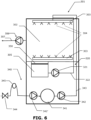
- the means for isolating, during the drying step, the chamber 302 at least partially from the liquid contained within the recirculation tank 305 may comprise, as shown in figure 6 , a selectively actuatable mechanic closure system 350 of the recirculation tank 305.
- the mechanic closure system 350 may be made in any suitable manner, among which merely by way of example, a sliding cover or a tiltable cover are mentioned, in either case formed by a single door or by plural doors, or also a shutter-like cover, namely formed by several concentric blades radially arranged, or a (blind-like) rolling shutter.
- the means for isolating, during the drying step, the chamber 302 at least partially from the liquid contained within the recirculation tank 305 may comprise, as shown in figure 7 , means 351 for emptying at least partially the recirculation tank 305, which are preferably actuated at the beginning of the drying step.
- the emptying means 351 may comprise, for example, a plug drain on the bottom of the recirculation tank 305 for emptying it by gravity, and/or a pump 352 and/or a draining electro-valve 353.
- the liquid removed from the recirculation tank 305 may, optionally, be temporarily stored in a special reservoir 354, in order to restore it in the recirculation tank 305 (or directly into the chamber 302) at the end of the drying step in order to reuse it in the successive sanitizing cycle.
- Pump 352 is preferably a reversible pump, so as to configure both the emptying means and the restoring means.
- a second pump (not shown) may be provided for in order to bring the liquid temporarily stored in the reservoir 354 back into the recirculation tank 305 (or directly into the chamber 302).
- FIGS 6 and 7 there are shown, as seen, different embodiments of the means for isolating the chamber 302 at least partially from the liquid contained within the recirculation tank 305, and a different arrangement of the vacuum generation device 306, among the various possible ones described above: it will be understood that those figures are representative of more embodiments, in that the means for isolating the chamber 302 shown in figure 7 may be used with the arrangement of the vacuum generation device 306 shown in figure 6 or according to the other variants set forth above; vice versa, the means for isolating the chamber 302 shown in figure 6 may be with the arrangement of the vacuum generation device 306 shown in figure 7 or according to the other variants set forth above.
- the means for isolating the chamber 302 may comprise the combination of those shown in figure 6 with those shown in figure 7 , and this with any of the arrangements of the vacuum generation device 306 according to figure 6 or according to figure 7 or according to the other variants set forth above. As mentioned above, furthermore, in any case it is not necessary for drying to occur merely by natural evaporation.
- a method disclosed herein for drying tableware, typically as part of a sanitizing method, in a cycle dishwasher comprising a single chamber 302 wherein tableware is sanitized comprises creating a vacuum within the chamber 302. The vacuum is created during at least a phase of the drying.
- the pressure within the chamber 302 is brought to a value below or equal to about 20.0 kPa, obtaining a water boiling point below 60°C, more preferably it is brought to a value below or equal to about 3.2 kPa, obtaining a water boiling point below 25°C.
- the method may preferably further comprise heating the chamber 302, more preferably to a decreasing temperature as the pressure decreases.
- the water evaporation temperature curve at different pressure for example, at 20.0 kPa the water evaporation temperature is about 55°C and therefore the chamber 302 may be heated at a temperature so low as about 55°C, for example in a range of about 55°C-100°C; conversely, at 3,2 kPa the water evaporation temperature is about 25°C and therefore the chamber 302 may be heated at a temperature so low as about 25°C, for example in a range of about 25°C-100°C; etc.
- the method may comprise forcing an airflow into the chamber 302, preferably an airflow with low humidity content and/or at high temperature (hot dry air).
- the temperature of the forced airflow is kept within the range 25°C-100°C, more preferably 25°C-60°C.
- the method may, additionally, comprise extracting water from the forced airflow, downstream of the chamber 302, and optionally recovering it.
- Said step of extracting and possibly recovering may comprise condensing the forced airflow, within or downstream of the chamber 302, preferably making it lap a condenser heat exchanger.
- Said step of extracting and possibly recovering may comprise, alternatively or additionally, adsorbing the water in the forced airflow, within or downstream of the chamber 302, preferably making it cross an adsorbing material, such as zeolites.
- the method disclosed herein may further comprise isolating the chamber 302 at least partially from the liquid contained within the recirculation tank 305 of the dishwasher 301, which is provided for collecting the liquid falling from the tableware during washing and/or rinsing steps of a sanitizing method of which the drying method forms part.
- Isolating may be performed during the entire drying or during part of the drying only.
- Isolating the chamber 302 at least partially may comprise selectively closing the recirculation tank 305 through a mechanic closure system 350.
- isolating the chamber 302 at least partially may comprise emptying at least partially the recirculation tank 305.
- the method further comprises temporarily storing the liquid withdrawn from the chamber 302.
- the method further comprises restoring within the recirculation tank 305 (or directly within the chamber 302) the liquid temporarily stored, preferably at the end of drying.
- a controller (not shown) controls and coordinates the operation of the components of the dishwasher machine 301 during the sanitizing cycle in order to obtain the above-described operation.
- the cycle dishwasher 401 comprises at least one washing circuit 420 and at least one rinsing circuit 440 which distribute liquid into a single chamber 402 wherein tableware is accommodated.
- Such a cycle dishwasher 401 comprises at least one arm and preferably, as shown, at least one pair of rotary or stationary arms 403 within chamber 402, provided with a plurality of nozzles 404 supplied with a washing liquid and/or a rinsing liquid, and a recirculation tank 405, which collects the washing liquid and/or rinsing liquid once it has been projected on the tableware e falls back therefrom.
- the arm(s) 403 and the recirculation tank 405 (or at least its opening, as shown) are arranged internal to the chamber 402.
- the washing liquid is typically water with detergent; the rinsing liquid is typically clean water (possibly added with rinse aid).
- the washing circuit 420 comprises the recirculation tank 405, a first pump 421, and a first tube assembly 422 connecting the tank 405 with the pump 421 and the pump 421 with the arms 403.
- the washing liquid which may arrive at least in part from the rinsing step of a preceding sanitizing cycle or from a preceding washing cycle of the same sanitizing cycle, is pumped from the recirculation tank 405 onto the tableware, and is again collected in the recirculation tank 405.
- the washing liquid solution is thus circulated between the tableware and the recirculation tank 405, without being discharged from the cycle dishwasher 401 unless, possibly and preferably only in part, at the end of the washing.
- the rinsing circuit 440 comprises a boiler 441, a second pump 442, a second tube assembly 443 connecting the boiler 441 to the second pump 442 and the second pump 442 to the arms 403, and the recirculation tank 405 only in its role of collector of the rinsing liquid.
- an electro-valve 444 is typically provided for, managing the supply of water from the water mains, as well as possibly a hydraulic non-return device 445 downstream of said electro-valve 444.
- a liquid treatment device i.e. a softener
- the arm(s) connected within the washing circuit 420 may be different from the arm(s) connected within the rinsing circuit 440, and be arranged there above or therebelow or integral therewith, for example in a cross-like configuration, in a manner per se well known.
- the arm(s) provided for are shared between the washing circuit 420 and the rinsing circuit 440 as in the configuration shown, on the arms there is typically provided a plurality of nozzles connected with the washing circuit 420 and a plurality of nozzles connected with the rinsing circuit 440; however in other configurations, the same nozzles 404 may be supplied with said liquids in successive steps.
- the dishwasher 401 comprises means for isolating, during the drying step, the chamber 402 at least partially from the liquid contained within the recirculation tank 405.
- Tableware drying step is provided for evaporating the liquid still present on the tableware after rinsing.
- the isolating means By preventing, through the isolating means, the steam emitted in the recirculation tank 405 from being able to reach the chamber 402, it is avoided that it condenses on the tableware, re-wetting them.
- the drying process is not hindered and a complete drying may be efficiently obtained.
- the drying step may occur by natural evaporation. While in the absence of the isolating means, in order to obtain natural evaporation it is typically necessary to draw the basket out of the chamber, thanks to the isolating means natural evaporation may instead occur also leaving the basket within the chamber 402 itself, and in even remarkably shorter times than the times in the absence of such means.
- the drying step may, alternatively, occur by natural evaporation in addition to heating of the chamber 402 through a suitable heating device (not shown), for example a suitable electric resistor. Thanks to the isolating means, the heating device may be of a limited size and/or power, with advantages in terms of cost, energy consumption and occupied space. Furthermore, also in this case the drying times are shortened.
- the drying step may occur through a "ventilation" system, wherein a forced airflow, preferably with low humidity content and/or at high temperature (hot dry air), is directed onto the tableware, typically through a fan (not shown), causing evaporation of the liquid still present on the tableware after the rinsing step.
- a forced airflow preferably with low humidity content and/or at high temperature (hot dry air)
- the temperature of the forced airflow may be kept at lower levels with respect to the temperature necessary in the absence of the isolating means, and/or the forced airflow may have a shorter overall duration, with analogous advantages in terms of costs, energy consumption, space occupied by a device for heating the forced air flow, shortened drying times.
- the drying step may occur through a "condensation and/or adsorption" system, wherein, possibly besides sending an airflow on the tableware as mentioned, there is a recovery system which captures the humidity of the washing chamber 402, favouring its transformation into water and its discharge or recirculation.
- the recovery system comprises for example a closed fluid circuit, including a condenser heat exchanger, for example a fin coil, immersed in said airflow within or downstream of the chamber 402, and/or adsorbing material, for example zeolites, equally immersed in said airflow within or downstream of the chamber 402.
- the isolating means has, also in this case, the advantages set forth above.
- the isolating means are particularly efficient in the case of drying at a higher temperature than ambient temperature, both in case of using a forced airflow, and in case of merely heating the chamber 402, but they prove advantageous also in the case of drying by natural evaporation.
- the isolating means may comprise, as shown in figure 8 , a selectively actuatable mechanic closure system 450 of the recirculation tank 405.
- the mechanic closure system 450 may be made in any suitable manner, among which merely by way of example, a sliding cover or a tillable cover are mentioned, in either case formed by a single door or by plural doors, or also a shutter-like cover, namely formed by several concentric blades radially arranged, or a (blind-like) rolling shutter.
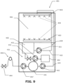
- the means for isolating, during the drying step, the chamber 402 at least partially from the liquid contained within the recirculation tank 405 may comprise, as shown in figure 9 , means 451 for emptying at least partially the recirculation tank 405, which are preferably actuated at the beginning of the drying step.
- the emptying means 451 may comprise, for example, a plug drain on the bottom of the recirculation tank 405 for emptying it by gravity, and/or a pump 452 and/or a draining electro-valve 453.
- the liquid removed from the recirculation tank 305 may, optionally, be temporarily stored in a special reservoir 454, in order to restore it in the recirculation tank 405 (or directly into the chamber 402) at the end of the drying step in order to reuse it in the successive sanitizing cycle.
- the pump 452 if provided for, is preferably a reversible pump so as to embody both the emptying means and the restoring means.
- a second pump (not shown) may be provided for in order to bring the liquid temporarily stored within the tank 454 back to the recirculation tank 405 (o directly into chamber 402).
- a method disclosed herein for drying tableware, typically as part of a sanitizing method, in a cycle dishwasher comprising a single chamber 402 wherein tableware is sanitized, and a recirculation tank 405 for collecting the liquid falling from the tableware, comprises isolating the chamber 402 at least partially from the liquid contained within the recirculation tank 405.
- Isolation may be carried out during the entire drying or during part of the drying only.
- Isolating the chamber 402 at least partially may comprise selectively closing the recirculation tank through a mechanic closure system 450.
- isolating the chamber 402 at least partially may comprise emptying at least partially the recirculation tank.
- the method further comprises temporarily storing the liquid withdrawn from the chamber 402.
- the method further comprises restoring, within the recirculation tank 405 (or directly within the chamber 402), the liquid temporarily stored, preferably at the end of the drying.
- the method may further comprise heating the chamber 402, preferably to a temperature above 60°C.
- the method may comprise forcing an airflow into the chamber 402, preferably with low humidity content and/or at high temperature (hot dry air).
- the temperature of the forced airflow is kept in the range 50°C-100°C, more preferably in the range 60-85°C.
- the method may, additionally, comprise extracting water from the forced airflow, within or downstream of the chamber 402, and optionally recovering it.
- Said step of removing and optionally recovering may comprise condensing the forced airflow, within or downstream of the chamber 402, preferably making it lap a condenser heat exchanger.
- Said step of extracting and optionally recovering may comprise, alternatively or additionally, adsorbing the water in the forced air flow, within or downstream of the chamber 402, preferably making it cross an adsorbing material, such as zeolites.
- a controller (not shown) controls and coordinates the operation of the components of the dishwasher machine 401 during the sanitizing cycle in order to obtain the above-described operation.
Landscapes
- Washing And Drying Of Tableware (AREA)
Abstract
A cycle dishwasher (301, 401) comprising a chamber (302, 402) wherein tableware is accommodated, and a recirculation tank (305, 405) for collecting the liquid falling from the tableware, comprises means (350, 351, 450, 451) for isolating, during at least part of a drying step of the tableware sanitizing cycle, the chamber (302, 402) at least partially from the liquid contained in the recirculation tank (305, 405), the recirculation tank (305, 405) being provided for collecting the rinsing water, and possibly the washing liquid solution falling from the tableware, in order to change a fraction of the washing liquid solution, to be used in the successive sanitizing cycles. A method for drying tableware in a cycle dishwasher (301, 401) comprising a single chamber (302, 402) wherein tableware is sanitized, and a recirculation tank (305, 405) for collecting the liquid falling from the tableware, the method comprising isolating the chamber (302, 402) at least partially from the liquid contained within the recirculation tank (305, 405), during the entire drying or during part of the drying only, the recirculation tank (305, 405) being provided for collecting the rinsing water, and possibly the washing liquid solution falling from the tableware, in order to change a fraction of the washing liquid solution, to be used in the successive sanitizing cycles.
Description
- The present invention relates to a tableware drying machine, and to a method for drying tableware in such a machine.
- The present invention also relates to a cycle dishwasher, and to a method for drying tableware in a cycle dishwasher, typically as part of a sanitizing method.
- Term "machine" will sometimes be omitted for the sake of brevity.
- Under term "tableware", both plates, cutlery and glasses, as generally understood, and also pans, containers, trays, kitchenware and other similar objects, are meant.
- Furthermore, for reasons of ease of reading, under term "tableware" also those means shall be meant, which support the above-mentioned tableware during the treatment within the drying machine, apart from when those supports are explicitly mentioned, or during the sanitizing process within the dishwasher.
- Under term "cycle" dishwasher, those machines are meant, wherein the tableware does not advance along a path, rather is sanitized remaining in the same environment.
- In order to sanitize tableware, while in the domestic field "cycle" dishwashers are used, in the professional field -which is the field of interest herein- and in particular in the context of catering for collective use, for example in the context of canteens, cycle dishwasher machines or "tunnel" dishwasher machines are generally used.
- In a cycle dishwasher, tableware is sanitized remaining stationary in the same environment or chamber, being subject to treatment steps following each other over time, which typically comprise a washing step, a rinsing step, and a drying step.
- In a tunnel dishwasher machine, tableware is displaced inside the tunnel, so as to pass through a plurality of working zones in succession, which typically comprise a washing zone, a rinsing zone, and a drying zone.
- In both cases, also a pre-washing step, respectively zone, and/or a pre-rinsing step, respectively zone, and/or a dripping step, respectively zone are meant.
- As far as drying of the tableware is concerned, in the cycle machines this may occur by natural evaporation (e.g. simply drawing the tableware support out of the chamber), possibly through an increase of the temperature of the chamber for example through an electric resistor, but normally it is made through a "ventilation" system, wherein a forced airflow, preferably with low humidity content and/or at high temperature, is directed onto the tableware, causing evaporation of the liquid still present after the rinsing step. "Condensation and/or adsorption" drying systems are also known, wherein besides sending an airflow onto the tableware, there is a recovery system which captures humidity from the chamber, favouring its transformation into water and the related discharge or recirculation.
- In tunnel machines, the drying step occurs in a corresponding manner, by providing for a sufficiently long and/or slowly crossed drying zone, possibly heated through an electric resistor and/or provided with a ventilation system and a possible condensation system, while usually adsorption systems are not used.
- In machines of both types, tableware drying is comparatively slow, with respect to other steps, affecting not a little the cycle time in a cycle machine and the length of a tunnel machine and/or the maximum tableware conveying speed within the latter.
- In the above-mentioned professional field, tableware drying machines are also known, despite less widespread and in general provided for large sanitizing volumes, into which the tableware which has been sanitized in a cycle or tunnel machine lacking the drying step or respectively zone are moved.
- In the present description and in the attached claims, under "tableware drying machine" a machine is meant, which is not intended for sanitizing the tableware through washing and/or rinsing and/or pre-washing and/or pre-rinsing and/or dripping. Such a machine, thus dedicated to the tableware drying step, may also be called "tableware purely drying machine", an expression that on the other hand should not be meant in a so limiting sense as to exclude other operations on the tableware, for example piling up, wrapping up, etc.
- A technical problem at the basis of the subject-matter disclosed herein is to provide a tableware drying machine which is particularly efficient, namely wherein the water evaporation on the tableware is more efficient.
- This is made by creating a vacuum within the drying chamber, which allows the water boiling point to be lowered with respect to the water boiling point at atmospheric pressure (100°C).
- Under term "vacuum", in the present description and in the attached claims a pressure below the atmospheric one is meant, including a pressure so low that it may be deemed "vacuum".
- An aspect of the subject-matter disclosed herein relates a tableware drying machine having the features of
claim 1. - A further aspect of the subject-matter disclosed herein relates to a method for drying tableware in such a machine, having the features of
claim 9. - Turning to another aspect of the subject-matter disclosed herein, in a "cycle" dishwasher machine, there are usually at least two rotary or fixed arms, one for washing and one for rinsing, wherein the hydraulic circuits supplying them are separate; the mechanical embodiment may be conceived in various forms, typically with integral washing arms and rinsing arms, for example in a so-called cross-like watermill, or overlapping ones.
- Alternatively, in a cycle dishwasher, the presence of a single arm or of a single arm pair may be provided for. In this case, the washing nozzles and the rinsing nozzles are typically separated on the same arm or on each arm of the pair, with still separate washing/rinsing supply hydraulic circuits.
- A schematic example of a
cycle dishwasher 100 is shown infigure 5 , wherein a washing circuit and rinsing one are recognizable, suitable to perform the washing and rinsing steps, respectively, in asingle chamber 110 suitable to accommodate tableware to be sanitized, and which is common to the two washing and rinsing circuits. - The washing circuit, shown in solid line, comprises a first pair of rotary or
stationary arms 101, provided with a plurality ofnozzles 102 supplied with a liquid washing solution through arecirculation tank 103, apump 104, and afirst tube assembly 105 connecting thewashing arms 101 with thepump 104, and thepump 104 itself with therecirculation tank 103. Thearms 101 and the recirculation tank 103 (or at least its top opening) are arranged withinchamber 110. - In the washing step, which may also take place according to subsequent cycles, the washing liquid solution is circulated between the tableware and the
recirculation tank 103, without being discharged from thecycle dishwasher 100; part of the washing liquid solution may be discharged at the end of the washing step and/or during the rinsing step. - The rinsing circuit, shown in dotted lines, comprises a second pair of rotary or
stationary arms 201, also provided with a plurality ofnozzles 202, an electro-valve 203 managing the water supply from the water mains, a hydraulicnon-return device 204 downstream of said electro-valve 203, and aboiler 205 downstream of said hydraulicnon-return device 204. Asecond tube assembly 206 connects theboiler 205 to said second pair ofarms 201. Thearms 201 are arranged withinchamber 110. - The rinsing circuit may comprise a
pump 207 arranged upstream or downstream of the boiler (both being shown infigure 5 by way of example), suitable for bringing liquid under pressure tonozzles 202. - Furthermore, in the rinsing circuit upstream of
boiler 205, there may be a liquid treatment device (i.e. a softener), not shown for the sake of simplicity. - Alternatively, both the washing and rinsing circuits supply a same pair of arms (or a single arm) provided with
washing nozzles 101 and withrinsing nozzles 201. - The rinsing circuit may also comprise, broadly speaking, the recirculation tank 103: while rinsing occurs with clean water coming from the water mains, the rinsing water - once it has been projected on the tableware - may be collected in the
recirculation tank 103 in order to change a fraction of the washing liquid solution itself, to be used in the successive sanitizing cycles. - The
recirculation tank 103 is therefore shared between the washing circuit and the rinsing one, but in the case of the rinsing circuit, it only serves as a liquid container. - At the end of the rinsing step, typically a tableware drying step is provided for. That step may occur by natural evaporation (e.g. simply drawing the basket out of chamber 110), possibly through an increase of the temperature of
chamber 110, for examples through an electric resistor, but usually it is carried out through a "ventilation" system, wherein a forced airflow, preferably with low humidity content and/or at high temperature, is directed onto the tableware, causing evaporation of the liquid still present after the rinsing step. - Furthermore, "condensation and/or adsorption" drying systems known, wherein besides sending an airflow onto the tableware, there is a recovery system which captures humidity from the washing chamber, favouring its transformation into water and the related discharge or recirculation.
- Another technical problem at the basis of the subject-matter disclosed herein is to optimize, in a cycle dishwasher, said drying step, irrespectively of which of the modes described above is used, thus rendering the water evaporation step on the tableware more efficient.
- This is made by creating a vacuum within the washing chamber, which allows the water boiling point to be lowered with respect to the water boiling point at atmospheric pressure (100°C).
- An aspect of the subject-matter disclosed herein relates to a cycle dishwasher comprising a chamber wherein tableware is accommodated, characterized in that the tableware drying machine comprises a selectively actuatable device for generating a vacuum within the chamber, the vacuum generating device being actuated during at least part of a drying step of the tableware sanitizing cycle.
- In the cycle dishwasher according to this aspect, the vacuum generation device may be configured to establish within the chamber a pressure below or equal to about 20.0 kPa, obtaining a water boiling point below 60°C, preferably a pressure below or equal to about 3.2 kPa, obtaining a water boiling point below 25°C.
- Alternatively or additionally, the cycle dishwasher according to this aspect may further comprise a selectively actuatable heating device for heating the chamber in a drying step.
- Alternatively or additionally, the cycle dishwasher according to this aspect may further comprise a device for forcing an airflow into the chamber during the drying step, distinct from or coinciding with said vacuum generation device, and optionally a condenser heat exchanger and/or an adsorbing material within the chamber or within the forced airflow, downstream of the chamber.
- Alternatively or additionally, the cycle dishwasher according to this aspect may further comprise means for isolating, during at least part of the drying step, the chamber at least partially from the liquid contained within a recirculation tank provided for collecting the liquid falling from the tableware.
- A further aspect of the subject-matter disclosed herein relates to a method for drying tableware in a cycle dishwasher comprising a single chamber wherein tableware is sanitized, the method comprising creating a vacuum within the chamber during at least a phase of the drying.
- In the method according to this aspect, the pressure within the chamber may be brought to a value below or equal to about 20.0 kPa, obtaining a water boiling point below 60°C, preferably it is brought to a value below or equal to about 3.2 kPa, obtaining a water boiling point below 25°C.
- Alternatively or additionally, the method according to this aspect may further comprise heating the chamber, preferably to a temperature decreasing as the pressure decreases.
- Alternatively or additionally, the method according to this aspect may further comprise forcing an airflow into the chamber, and optionally extracting water from the forced airflow, downstream of the chamber, through condensation and/or adsorption.
- Alternatively or additionally, the method according to this aspect may further comprise isolating the chamber at least partially from the liquid contained within a recirculation tank of the dishwasher, during the entire drying or during part of the drying only.
- Another technical problem at the basis of the subject-matter disclosed herein is to optimize, in a cycle dishwasher, the drying step, irrespectively of which of the modes described above is used, thus rendering the step of evaporating the water on the tableware more efficient.
- This is made by preventing the steam emitted in the recirculation tank from being able to reach the chamber, where it could condense on the tableware, hindering the drying process and possibly preventing full drying.
- An aspect of the present invention relates to a cycle dishwasher comprising a chamber wherein tableware is accommodated, and a recirculation tank for collecting the liquid falling from the tableware, characterized in that the dishwasher comprises means for isolating, during at least part of a drying step of the tableware sanitizing cycle, the chamber at least partially from the liquid contained within the recirculation tank.
- In the dishwasher according to this aspect, the isolating means may comprise a selectively actuatable mechanic closure system of the recirculation tank.
- Alternatively or additionally, in the dishwasher according to this aspect, the isolating means may comprise means for emptying at least partially the recirculation tank.
- The dishwasher may then further comprise a reservoir for temporarily storing the liquid withdrawn from the recirculation tank by said emptying means.
- The dishwasher may then further comprise means for restoring, in the recirculation tank or directly within the chamber, the temporarily stored liquid.
- Alternatively or additionally, the dishwasher according to this aspect may further comprise a selectively actuatable heating device for heating the chamber in a drying step.
- Alternatively or additionally, the dishwasher according to this aspect may further comprise a device for forcing an airflow into the chamber during the drying step, wherein preferably the airflow temperature is kept in the range 50°C-100°C, preferably in the range 60-85°C, and optionally a condenser heat exchanger and/or an adsorbing material within the chamber or within the forced airflow, downstream of the chamber.
- A further aspect of the subject-matter disclosed herein relates to a method for drying tableware in a cycle dishwasher comprising a single chamber wherein tableware is sanitized, and a recirculation tank for collecting the liquid falling from the tableware, the method comprising isolating the chamber at least partially from the liquid contained within the recirculation tank, during the entire drying or during part of the drying only.
- In the method according to this aspect, isolating the chamber at least partially may comprise selectively closing the recirculation tank through a mechanic closure system.
- Alternatively or additionally, in the method according to this aspect, isolating the chamber at least partially may comprise emptying at least partially the recirculation tank.
- The method may then further comprise temporarily storing the liquid withdrawn from the chamber.
- The method may then further comprise restoring, within the recirculation tank or directly within the chamber, the liquid temporarily stored, preferably at the end of the drying.
- Alternatively or additionally, the method according to this aspect may further comprise heating the chamber, preferably to a temperature above 60°C.
- Alternatively or additionally, the method according to this aspect may further comprise forcing an airflow into the chamber, wherein preferably the airflow temperature is kept in the range 50°C-100°C, more preferably in the range 60-85°C, and optionally extracting water from the forced airflow, within or downstream of the chamber, through condensation and/or adsorption.
- Further features and advantages of the machines and the methods according to the subject-matter disclosed herein will become clearer from the following detailed description, by way of non-limiting example, made with reference to the attached schematic drawings, wherein:
-
figure 1 is a block diagram of a tableware drying machine according to an aspect of the subject-matter disclosed herein, -
figure 2 is a block diagram of another tableware drying machine according to that aspect of the subject-matter disclosed herein, -
figure 3 is a schematic view of a tableware drying machine according to that aspect of the subject-matter disclosed herein, configured to be coupled with a cycle dishwasher machine; and -
figure 4 is a schematic view of a tableware drying machine according to said aspect of the subject-matter disclosed herein is, configured to be coupled with a tunnel dishwasher machine; -
figure 5 is a schematic view of a cycle dishwasher machine according to the prior art; -
figures 6 and7 illustrate, in a totally schematic manner, two illustrative embodiments of a dishwasher machine according to another aspect of the subject-matter disclosed herein; -
figures 8 and9 illustrate, in a totally schematic manner, two illustrative embodiments of a dishwasher machine according to still another aspect of the subject-matter disclosed herein. - With reference to
figure 1 , atableware drying machine 1 comprises a dryingchamber 2, configured to - temporarily - accommodate tableware to be dried after having been sanitized in a dishwasher machine (not shown). The dishwasher machine may totally lack the drying zone, respectively step, or it may have a preliminary drying zone, respectively step, for example a dripping zone in a tunnel dishwashing machine. - The
tableware drying machine 1 comprises adevice 3 for generating a vacuum withinchamber 2. - Tableware drying is provided for evaporating the liquid still present on the tableware after rinsing. By reducing the pressure within the chamber below the atmospheric pressure through the
vacuum generation device 3, the water boiling point is lowered, which may thus evaporate at temperatures below 100°C. - Preferably, the
vacuum generation device 3 is configured to establish within the chamber 2 a pressure below or equal to about 20.0 kPa, obtaining a water boiling point below 60°C. - More preferably, the
vacuum generation device 3 is configured to establish within the chamber 2 a pressure below or equal to about 3.2 kPa, obtaining a water boiling point below 25°C. - Drying within the
chamber 2 may occur by natural evaporation. In the absence of thepressure generation device 3, in order to obtain natural evaporation in a cycle dishwasher it is typically necessary to draw a tableware support, for example a basket, out of the sanitizing chamber; in a tunnel dishwasher machine it is typically necessary to provide for a zone of the sanitizing tunnel which is long enough and/or within which tableware is conveyed at a sufficiently low speed. - Thanks to the
vacuum generation device 3, natural evaporation may instead occur leaving the tableware, including a possible support therefor, for example a basket, in thechamber 2 for even remarkably shorter times than the times in the absence of such a device. - The drying step may, alternatively, occur by natural evaporation in addition to heating of the
chamber 2 through asuitable heating device 4, which is therefore optional, for example a suitable electric resistor. Thanks to thevacuum generation device 3, theheating device 4 may be of a limited size and/or power, with advantages in terms of cost, energy consumption and occupied space. Furthermore, also in this case the drying times are shortened. - According to an alternative, drying may occur through a "ventilation" system, wherein a forced airflow, preferably with low humidity content and/or at high temperature (hot dry air), is directed onto the tableware causing evaporation of the liquid still present on the tableware after the rinsing which occurred in the dishwasher machine operatively coupled with the
tableware drying machine 1. Infigure 1 there are schematically shown afan 5 and a heating device 6 external tochamber 2, equally optional, for accomplishing said ventilation drying. However, thefan 5 might coincide with thevacuum generation device 3 and/or the heating device 6 might coincide with theheating device 4. - Thanks to the
vacuum generation device 3, the temperature of the forced airflow may be kept at lower levels with respect to the temperature necessary in the absence of thevacuum generation device 3, and/or the forced airflow may have a shorter overall duration and/or lower throughput, with analogous advantages in terms of costs, energy consumption, space occupied by a device for heating the forced air flow, shortened drying times. - According to another alternative, drying may occur through a "condensation and/or adsorption" system, wherein, possibly besides sending an airflow onto the tableware as mentioned, there is a
recovery system 7 which captures the humidity of thechamber 2, favouring its transformation into water and its discharge or recirculation.Recovery system 7 comprises for example a fluid circuit, which may include acondenser heat exchanger 8, for example a fin coil, immersed in said airflow downstream of thechamber 2 as shown, or withinchamber 2. - Alternatively or additionally to the condenser heat exchanger 8 - and in parallel thereto or in series thereto -, the
recovery system 7 may comprise an adsorbingmaterial 9, for example zeolites, equally immersed in said airflow within or downstream of thechamber 2 as shown. - Steam coming from the tableware is conveyed onto the
heat exchanger 8 and/or onto the adsorbingmaterial 9 of therecovery system 7, and transformed into water, ready to be discharged through thedrain 10 or possibly recycled in a dishwasher machine operatively coupled with thetableware drying machine 1. Thevacuum generation device 3 has, also in this case, the advantages set forth above. - Advantageously, in a ventilation and condensation and/or adsorption system, as shown, a
closed fluid circuit 11 is embodied, comprising saidfan 5 and the heating device 6 upstream of thechamber 2, thechamber 2 itself, and therecovery system 7 downstream of or withinchamber 2, the above-mentioned variants being however possible. - In all the above cases, the
vacuum generation device 3 may be selected among a vacuum pump, a blower and a fan. - In the embodiment shown in
figure 1 , thevacuum generation device 3 is arranged internal tochamber 2 of thetableware drying machine 1. - In the embodiment shown in
figure 2 , thevacuum generation device 3 is arranged external tochamber 2 or even (not shown) external to a casing of thetableware drying machine 1, possibly also being, advantageously, in the form of an update kit. - The
vacuum generation device 3 may for example be housed within the "technical compartment" wherein other components are housed, such as for example the above-mentioned components 5-9, or it may be housed separate from the other components 5-9, in an ad hoc technical compartment. Atube assembly vacuum generation device 3 to the external environment on the one side (fig. 1 ,fig. 2 ) and tochamber 2 on the other side (fig. 2 ). - For the rest, for the tableware drying machine of
figure 2 and for the other embodiments now described, all the variants and optional features set forth thus far for thetableware drying machine 1 offigure 1 hold true. - The
tableware drying machine 1 has the advantage that drying takes place in an environment lacking supply circuits of water and liquid solutions. - Furthermore, it is possible to simultaneously treat a tableware batch in a dishwasher machine for sanitizing it, and another tableware batch in the
tableware drying machine 1 for drying it. - Furthermore, by suitably sizing the
tableware drying machine 1, or by providing for a suitable number thereof, it is possible to treat a tableware volume per time unit analogous to that treated for sanitizing it. - Therefore, drying does not represent any more a slowdown in overall tableware treatment.
- The provision of the
vacuum generation device 3 internal tochamber 2 optimizes, as mentioned, the drying in terms of times and/or spaces and/or energy, maximizing these advantages, besides offering the further advantages that have been previously discussed, and those discussed hereinbelow. - A further advantage of the
tableware drying machine 1 is the possibility of drying in a relatively quick and complete manner also tableware which is typically very difficult to dry, such as for example disposable plastic cups and trays, which typically require ad hoc machines in order to be properly dried. -
Figure 3 schematically shows atableware drying machine 20 particularly (but not necessarily) configured to be operatively coupled with a cycle dishwasher (not shown). In thetableware drying machine 20,chamber 2 is a stationary accommodation chamber, and it comprises a single tableware input andoutput opening 21, provided with a vacuum tight closure system, for example ahood 22 as shown, or a gate closure or a door closure. Tableware to be dried is preferably loaded into thetableware drying machine 20 by using a support, for example a basket, therefore the operatively coupled cycle dishwasher is preferably of the type with removable basket. An operator attends, after having possibly drawn a basket with dry tableware out of thetableware drying machine 20, to move a basket with sanitized tableware from the cycle dishwasher to thetableware drying machine 20, and to insert a basket, with dirty tableware, into the cycle dishwasher. Alternatively, one or more devices suitably configured for such handling may be provided for. -
Figure 4 schematically shows atableware drying machine 30 particularly (but not necessarily) configured to be operatively coupled with a tunnel dishwasher machine (not shown). In thetableware drying machine 30, thechamber 2 is of the tunnel type, and it comprises a tableware input opening 31 and atableware output opening 32, preferably arranged on opposite sides of thetableware drying machine 30, as shown. However, other configurations are possible, for example wherein theinput opening 31 and theoutput opening 32 are on adjacent sides of the tableware drying machine, so that the tableware conveying direction within the tableware drying machine is deviated by 90°. - The
input opening 31 and theoutput opening 32 are provided with a respective vacuum tight closure system, for example a respective vertically sliding closure door (hand operated or automated), of which theclosure system 33 of theoutput opening 32 is visible. - A
conveyor device 34 for the tableware to be driedcrosses chamber 2 from the input opening 31 to theoutput opening 32; the loading and movement parameters of theconveyor device 34, as well as the opening and closure of the input andoutput openings chamber 2 for a time suitable for drying. - The
conveyor device 34 may be of the flight-type or of the rack-conveyor type. - The
conveyor device 34 is preferably adjacent and successive to a conveyor device (not shown) of the tunnel dishwasher machine operatively coupled with thetableware drying machine 30 or to a conveyor device arranged therebetween. The tableware conveying direction may be the same, or the two adjacent conveyor devices may have different conveying directions, for example orthogonal to each other. - Tableware to be dried is then, advantageously, automatically loaded into the
tableware drying machine 20 from the tunnel dishwasher machine. - The loading and movement parameters of the
conveyor device 34 are set, and possibly adjustable, according to the length ofchamber 2 from the input opening 31 to theoutput opening 32, the power of the components 5-9, the tableware volume to be treated, the ambient air temperature and humidity conditions, the humidity conditions of the input tableware, typically exiting from the dishwasher machine operatively coupled with thetableware drying machine chamber 2 and/or other conditions, as will be manifest to those skilled in the art in the light of the present description. For example, it is possible to loadconveyor device 34 with tableware batches separated by empty spaces, and keep theconveyor device 34 always moving; or it is possible to load theconveyor device 34 with tableware batches essentially not spaced from each other, and move it with an intermittent movement so that each batch remains stationary withinchamber 2 for a time suitable for drying. In both cases, the opening and closure of the input andoutput openings - The
vacuum generation device 3 may be selectively actuated. For example, it may be actuated during the entire drying of a tableware batch, for example for the entire duration of the treatment within the stationary accommodation chamber of thetableware drying machine 20 offigure 3 , or for the entire length of the tunnel chamber of thetableware drying machine 30 offigure 4 . Alternatively, it may only be actuated during one or more time intervals, respectively in one or more zones of the tunnel chamber. - In all embodiments of the tableware drying machine disclosed herein, the conditions which may influence the selective actuation of the
vacuum generation device 3, as well as the generated vacuum degree, are those indicated above with respect to the loading and movement parameters of theconveyor device 34. - Advantageously, the
tableware drying machine 1 may be provided with sensors (not shown), such as for example a humidity probe, allowing one or more operating conditions to be detected, used in order to automatically adjust the selective actuation of thevacuum generation device 3, its power, the duration of the drying cycle, and any other operating variable of components 5-9. - Manifestly, the
tableware drying machine 1 may also be used to dry tableware which has been sanitized by hand. - A method disclosed herein for drying tableware comprises providing for a tableware drying machine comprising a
chamber 2 wherein tableware is accommodated, and creating a vacuum in thechamber 2. - The vacuum is created during at least a phase of the drying.
- The drying is typically successive to tableware sanitizing.
- Preferably the pressure within the
chamber 2 is brought to a value below or equal to about 20.0 kPa, obtaining a water boiling point below 60°C, more preferably it is brought to a pressure below or equal to about 3.2 kPa, obtaining a water boiling point below 25°C. - The method may preferably further comprise heating the
chamber 2, more preferably to a decreasing temperature as the pressure decreases. According to the water evaporation temperature curve at different pressures, for example, at 20.0 kPa the water evaporation temperature is about 55°C and therefore thechamber 2 may be heated at a temperature so low as about 55°C, for example in a range of about 55°C-100°C; conversely, at 3,2 kPa the water evaporation temperature is about 25°C and therefore thechamber 2 may be heated at a temperature so low as about 25°C, for example in a range of about 25°C-100°C; etc. - Alternatively or additionally, the method may comprise forcing an airflow into the
chamber 2, preferably an airflow with low humidity content and/or at high temperature (hot dry air). - Preferably the temperature of the forced airflow is kept within the range 25°C-100°C, more preferably 25°C-60°C.
- The method may, additionally, comprise extracting water from the forced airflow, downstream of the
chamber 2, and optionally recover it, for example in a dishwasher machine operatively coupled with thetableware drying machine 1. - Said step of extracting and possibly recovering may comprise condensing the forced airflow, within or downstream of the
chamber 2, preferably making it lap acondenser heat exchanger 9. - Said step of extracting and optionally recovering may comprise, alternatively or additionally, adsorbing the water in the forced airflow, within or downstream of the
chamber 2, preferably making it cross an adsorbingmaterial 8, such as zeolites. - A controller (not shown) controls and coordinates the operation of the components of the
tableware drying machine 1 during drying in order to obtain the above-described operation; the controller further receives as input the outputs detected by the possible sensors. - With reference to
figure 6 , thecycle dishwasher machine 301 comprises at least onewashing circuit 320 and at least onerinsing circuit 340, which distribute liquid in asingle chamber 302 wherein tableware is accommodated. - That
cycle dishwasher 301 comprises at least one arm and preferably, as shown, at least one pair of rotary orstationary arms 303 within thechamber 302, provided with a plurality ofnozzles 304 supplied with a washing liquid and/or with a rinsing liquid, and arecirculation tank 305 which collects the washing or rinsing liquid once it has been projected on the tableware and falls therefrom. The arm(s) 303 and the recirculation tank 305 (or at least its opening, as shown) is/are arranged within thechamber 302. - The washing liquid is typically water with detergent; the rinsing liquid is typically clean water (possibly added with rinse aid).
- The
washing circuit 320 comprises therecirculation tank 305, afirst pump 321 and afirst tube assembly 322 connecting thetank 305 to thepump 321 and thepump 321 to thearms 303. - The washing liquid, which may come at least in part from the rinsing step of a preceding sanitizing cycle or from a preceding washing cycle of the same sanitizing cycle, is pumped from the
recirculation tank 305 onto the tableware, and is collected again in therecirculation tank 305. In the washing step, which may also occur according to successive cycles, the washing liquid solution is thus circulated between the tableware and therecirculation tank 305, without being discharged from thecycle dishwasher 301 apart, possibly and preferably only in part, at the end of the washing. - The
rinsing circuit 340 comprises aboiler 341, asecond pump 342, asecond tube assembly 343 connecting theboiler 341 to thesecond pump 342 and thesecond pump 342 to thearms 303, and therecirculation tank 305 only in its role of collector of the rinsing liquid. Upstream of theboiler 341, there is typically provided for an electro-valve 344, managing the water supply from the water mains, and possibly a hydraulicnon-return device 345 downstream of said electro-valve 344. - Alternatively:
- the
pump 342 may be provided for upstream of theboiler 341, as shown by pump 342'; - besides
pump 342, a second pump 342' may be provided for, upstream of theboiler 341; - no pump may be provided for.
- Furthermore, in the
rinsing circuit 340 upstream of theboiler 341 there may optionally be a liquid treatment device (i.e. a softener), not shown for the sake of simplicity. - In alternative configurations, the arm(s) connected in the
washing circuit 320 may be different from the arm(s) connected in therinsing circuit 340, and be arranged above or below or integral thereto, for example in a cross-like configuration, in a manner well known per se. When the arm(s) provided for are shared between thewashing circuit 320 and therinsing circuit 340 as in the configuration shown, on the arms there are typically provided a plurality of nozzles connected with thewashing circuit 320 and a plurality of nozzles connected with therinsing circuit 340; however, in other configurations, thesame nozzles 304 may be supplied with said liquids in successive steps. - According to the subject-matter disclosed herein, the
dishwasher 301 further comprises adevice 306 for generating a vacuum within thechamber 302. - Under term "vacuum", in the present description and in the attached claims a pressure below the atmospheric one is meant, including a pressure so low that it may be considered "vacuum".
- The
vacuum generation device 306 is selectively actuatable, and in particular it is actuated during at least part of a tableware drying step of the tableware sanitizing cycle. The drying step is provided for at the end of a rinsing step, in turn preceded by a washing step. - The tableware drying step is provided for evaporating the liquid still present on the tableware after the rinsing step. By reducing the pressure within the
chamber 302 below the atmospheric pressure through thevacuum generation device 306, the water boiling point is lowered, which may therefore evaporate at temperatures below 100°C. - Preferably, the
vacuum generation device 306 is configured to establish within the chamber 302 a pressure below or equal to about 20.0 kPa, obtaining a water boiling point below 60°C. - More preferably, the
vacuum generation device 306 is configured to establish within the chamber 302 a pressure below or equal to about 3.2 kPa, obtaining a water boiling point below 25°C. - The drying may occur by natural evaporation. While in the absence of the
pressure generation device 306, in order to obtain natural evaporation it is typically necessary to draw the basket out of the chamber, thanks to thevacuum generation device 306, natural evaporation may instead also occur leaving the basket in thechamber 2 itself, and in even remarkably shorter time than the times in the absence of such a device. - The drying step may, alternatively, occur by natural evaporation in addition to heating of the
chamber 302 through a suitable heating device (not shown), for example a suitable electric resistor. Thanks to thevacuum generation device 306, the heating device may be of a limited size and/or power, with advantages in terms of cost, energy consumption and occupied space. Furthermore, also in this case the drying times are shortened. - According to an alternative (not shown), drying may occur through a "ventilation" system, wherein a forced airflow, preferably with low humidity content and/or at high temperature (hot dry air), is directed onto the tableware, typically through a fan (not shown), causing evaporation of the liquid still present after the rinsing step. Thanks to the
vacuum generation device 306, the temperature of the forced airflow may be kept at lower levels with respect to the temperature necessary in the absence of thevacuum generation device 306, and/or the forced airflow may have a shorter overall duration, with analogous advantages in terms of costs, energy consumption, space occupied by a device for heating the forced air flow, shortened drying times. - According to another alternative (not shown), drying may occur through a "condensation and/or adsorption" system, wherein, possibly besides sending an airflow on the tableware as mentioned, there is a recovery system which captures the humidity of the
chamber 302, favouring its transformation into water and its discharge or recirculation. Recovery system comprises for example a closed fluid circuit, including a condenser heat exchanger, for example a fin coil, immersed in said airflow within or downstream of thechamber 302 as shown, and/or an adsorbing material, for example zeolites, equally immersed in said airflow within or downstream of thechamber 302. Steam coming from the tableware is conveyed onto the heat exchanger and/or onto the adsorbing material of the recovery system, and transformed into water, ready to be discharged through the drain or possibly recycled through therecirculation tank 305. The vacuum generation means 306 have, also in this case, the advantages set forth above. - In all the above cases, the
vacuum generation device 306 may be selected among a vacuum pump, a blower and a fan. - In the embodiment shown in
figure 6 , thevacuum generation device 306 is arranged external to thedishwasher 301, advantageously also possibly being in the form of an update kit. Atube assembly 307 connects the vacuum generation device 6 to thechamber 302 on the one side, and to the external environment on the other side. - In the embodiment shown in
figure 7 , thevacuum generation device 306 is arranged internal to thechamber 302 of thedishwasher 301. - In other embodiments, not shown, the
vacuum generation device 306 is arranged internal to thedishwasher 301, but external tochamber 302. Thevacuum generation device 306 may be for example housed within the "technical compartment" wherein other components are housed, such as for example thewashing pump 321, the rinsingpump 342, 342', theboiler 341 etc., or it may be housed separate from the other components, in an ad hoc technical compartment. Also in these embodiments, thevacuum generation device 306 is connected to thechamber 302 on the one side, and to the external environment on the other side by a tube assembly. - For the rest, for the dishwasher of
figure 7 and for the other embodiments now described, all the variants and optional features set forth thus far for thedishwasher 301 offigure 6 hold true. - In the case of ventilation or condensation and/or adsorption evaporation, the
vacuum generation device 306 may also coincide with the fan creating the forced airflow, in both the arrangements according tofigure 6 orfigure 7 . - According to another aspect particularly innovative per se, which may also be applied in the absence of the
vacuum generation device 306, during the drying step thechamber 302 is at least partially isolated from the liquid contained withinrecirculation tank 305. In that manner, it is avoided that steam emitted within therecirculation tank 305 may reach thechamber 302, where it could condense on the tableware hindering the drying process, and possibly preventing full drying. This drawback of the cycle dishwashers of the prior art is most felt in the case of drying at a higher temperature than ambient temperature, both in case of using a forced airflow, and in the case of merely heating thechamber 302, however the innovative provision proves to be advantageous also in the case of drying by natural evaporation. - The means for isolating, during the drying step, the
chamber 302 at least partially from the liquid contained within therecirculation tank 305 may comprise, as shown infigure 6 , a selectively actuatablemechanic closure system 350 of therecirculation tank 305. Themechanic closure system 350 may be made in any suitable manner, among which merely by way of example, a sliding cover or a tiltable cover are mentioned, in either case formed by a single door or by plural doors, or also a shutter-like cover, namely formed by several concentric blades radially arranged, or a (blind-like) rolling shutter. - The means for isolating, during the drying step, the
chamber 302 at least partially from the liquid contained within therecirculation tank 305 may comprise, as shown infigure 7 , means 351 for emptying at least partially therecirculation tank 305, which are preferably actuated at the beginning of the drying step. - The emptying means 351 may comprise, for example, a plug drain on the bottom of the
recirculation tank 305 for emptying it by gravity, and/or apump 352 and/or a draining electro-valve 353. - Instead of being discharged, the liquid removed from the
recirculation tank 305 may, optionally, be temporarily stored in aspecial reservoir 354, in order to restore it in the recirculation tank 305 (or directly into the chamber 302) at the end of the drying step in order to reuse it in the successive sanitizing cycle. -
Pump 352, if provided for, is preferably a reversible pump, so as to configure both the emptying means and the restoring means. Alternatively, a second pump (not shown) may be provided for in order to bring the liquid temporarily stored in thereservoir 354 back into the recirculation tank 305 (or directly into the chamber 302). - In
figures 6 and7 there are shown, as seen, different embodiments of the means for isolating thechamber 302 at least partially from the liquid contained within therecirculation tank 305, and a different arrangement of thevacuum generation device 306, among the various possible ones described above: it will be understood that those figures are representative of more embodiments, in that the means for isolating thechamber 302 shown infigure 7 may be used with the arrangement of thevacuum generation device 306 shown infigure 6 or according to the other variants set forth above; vice versa, the means for isolating thechamber 302 shown infigure 6 may be with the arrangement of thevacuum generation device 306 shown infigure 7 or according to the other variants set forth above. Furthermore, the means for isolating thechamber 302 may comprise the combination of those shown infigure 6 with those shown infigure 7 , and this with any of the arrangements of thevacuum generation device 306 according tofigure 6 or according tofigure 7 or according to the other variants set forth above. As mentioned above, furthermore, in any case it is not necessary for drying to occur merely by natural evaporation. - A method disclosed herein for drying tableware, typically as part of a sanitizing method, in a cycle dishwasher comprising a
single chamber 302 wherein tableware is sanitized, comprises creating a vacuum within thechamber 302. The vacuum is created during at least a phase of the drying. - Preferably the pressure within the
chamber 302 is brought to a value below or equal to about 20.0 kPa, obtaining a water boiling point below 60°C, more preferably it is brought to a value below or equal to about 3.2 kPa, obtaining a water boiling point below 25°C. - The method may preferably further comprise heating the
chamber 302, more preferably to a decreasing temperature as the pressure decreases. According to the water evaporation temperature curve at different pressure, for example, at 20.0 kPa the water evaporation temperature is about 55°C and therefore thechamber 302 may be heated at a temperature so low as about 55°C, for example in a range of about 55°C-100°C; conversely, at 3,2 kPa the water evaporation temperature is about 25°C and therefore thechamber 302 may be heated at a temperature so low as about 25°C, for example in a range of about 25°C-100°C; etc. - Alternatively, the method may comprise forcing an airflow into the
chamber 302, preferably an airflow with low humidity content and/or at high temperature (hot dry air). - Preferably the temperature of the forced airflow is kept within the range 25°C-100°C, more preferably 25°C-60°C.
- The method may, additionally, comprise extracting water from the forced airflow, downstream of the
chamber 302, and optionally recovering it. - Said step of extracting and possibly recovering may comprise condensing the forced airflow, within or downstream of the
chamber 302, preferably making it lap a condenser heat exchanger. - Said step of extracting and possibly recovering may comprise, alternatively or additionally, adsorbing the water in the forced airflow, within or downstream of the
chamber 302, preferably making it cross an adsorbing material, such as zeolites. - The method disclosed herein, irrespectively of the presence or absence of the other features now mentioned, may further comprise isolating the
chamber 302 at least partially from the liquid contained within therecirculation tank 305 of thedishwasher 301, which is provided for collecting the liquid falling from the tableware during washing and/or rinsing steps of a sanitizing method of which the drying method forms part. - Isolating may be performed during the entire drying or during part of the drying only.
- Isolating the
chamber 302 at least partially may comprise selectively closing therecirculation tank 305 through amechanic closure system 350. - Alternatively or additionally, isolating the
chamber 302 at least partially may comprise emptying at least partially therecirculation tank 305. - Preferably, the method further comprises temporarily storing the liquid withdrawn from the
chamber 302. - Preferably, the method further comprises restoring within the recirculation tank 305 (or directly within the chamber 302) the liquid temporarily stored, preferably at the end of drying.
- A controller (not shown) controls and coordinates the operation of the components of the
dishwasher machine 301 during the sanitizing cycle in order to obtain the above-described operation. - With reference to
figure 8 , thecycle dishwasher 401 comprises at least onewashing circuit 420 and at least onerinsing circuit 440 which distribute liquid into asingle chamber 402 wherein tableware is accommodated. - Such a
cycle dishwasher 401 comprises at least one arm and preferably, as shown, at least one pair of rotary orstationary arms 403 withinchamber 402, provided with a plurality ofnozzles 404 supplied with a washing liquid and/or a rinsing liquid, and arecirculation tank 405, which collects the washing liquid and/or rinsing liquid once it has been projected on the tableware e falls back therefrom. The arm(s) 403 and the recirculation tank 405 (or at least its opening, as shown) are arranged internal to thechamber 402. - The washing liquid is typically water with detergent; the rinsing liquid is typically clean water (possibly added with rinse aid).
- The
washing circuit 420 comprises therecirculation tank 405, afirst pump 421, and afirst tube assembly 422 connecting thetank 405 with thepump 421 and thepump 421 with thearms 403. - The washing liquid, which may arrive at least in part from the rinsing step of a preceding sanitizing cycle or from a preceding washing cycle of the same sanitizing cycle, is pumped from the
recirculation tank 405 onto the tableware, and is again collected in therecirculation tank 405. In the washing step, which may also occur according to successive cycles, the washing liquid solution is thus circulated between the tableware and therecirculation tank 405, without being discharged from thecycle dishwasher 401 unless, possibly and preferably only in part, at the end of the washing. - The
rinsing circuit 440 comprises aboiler 441, asecond pump 442, asecond tube assembly 443 connecting theboiler 441 to thesecond pump 442 and thesecond pump 442 to thearms 403, and therecirculation tank 405 only in its role of collector of the rinsing liquid. Upstream of theboiler 441, an electro-valve 444 is typically provided for, managing the supply of water from the water mains, as well as possibly a hydraulicnon-return device 445 downstream of said electro-valve 444. - Alternatively:
- pump 442 may be provided for upstream of the
boiler 441, as shown by pump 442'; - besides
pump 442, a second pump 442' may be provided for, upstream of theboiler 441; - no pump may be provided for.
- Furthermore, in the
rinsing circuit 440 upstream of theboiler 441 there may optionally be a liquid treatment device (i.e. a softener), not shown for the sake of simplicity. - In alternative configurations, the arm(s) connected within the
washing circuit 420 may be different from the arm(s) connected within therinsing circuit 440, and be arranged there above or therebelow or integral therewith, for example in a cross-like configuration, in a manner per se well known. When the arm(s) provided for are shared between thewashing circuit 420 and therinsing circuit 440 as in the configuration shown, on the arms there is typically provided a plurality of nozzles connected with thewashing circuit 420 and a plurality of nozzles connected with therinsing circuit 440; however in other configurations, thesame nozzles 404 may be supplied with said liquids in successive steps. - According to the subject-matter disclosed herein is, the
dishwasher 401 comprises means for isolating, during the drying step, thechamber 402 at least partially from the liquid contained within therecirculation tank 405. - Tableware drying step is provided for evaporating the liquid still present on the tableware after rinsing. By preventing, through the isolating means, the steam emitted in the
recirculation tank 405 from being able to reach thechamber 402, it is avoided that it condenses on the tableware, re-wetting them. The drying process is not hindered and a complete drying may be efficiently obtained. - The drying step may occur by natural evaporation. While in the absence of the isolating means, in order to obtain natural evaporation it is typically necessary to draw the basket out of the chamber, thanks to the isolating means natural evaporation may instead occur also leaving the basket within the
chamber 402 itself, and in even remarkably shorter times than the times in the absence of such means. - The drying step may, alternatively, occur by natural evaporation in addition to heating of the
chamber 402 through a suitable heating device (not shown), for example a suitable electric resistor. Thanks to the isolating means, the heating device may be of a limited size and/or power, with advantages in terms of cost, energy consumption and occupied space. Furthermore, also in this case the drying times are shortened. - According to an alternative (not shown), the drying step may occur through a "ventilation" system, wherein a forced airflow, preferably with low humidity content and/or at high temperature (hot dry air), is directed onto the tableware, typically through a fan (not shown), causing evaporation of the liquid still present on the tableware after the rinsing step. Thanks to the isolating means, the temperature of the forced airflow may be kept at lower levels with respect to the temperature necessary in the absence of the isolating means, and/or the forced airflow may have a shorter overall duration, with analogous advantages in terms of costs, energy consumption, space occupied by a device for heating the forced air flow, shortened drying times.
- According to another alternative (not shown), the drying step may occur through a "condensation and/or adsorption" system, wherein, possibly besides sending an airflow on the tableware as mentioned, there is a recovery system which captures the humidity of the
washing chamber 402, favouring its transformation into water and its discharge or recirculation. The recovery system comprises for example a closed fluid circuit, including a condenser heat exchanger, for example a fin coil, immersed in said airflow within or downstream of thechamber 402, and/or adsorbing material, for example zeolites, equally immersed in said airflow within or downstream of thechamber 402. Steam coming from the tableware is conveyed onto the heat exchanger and/or onto the adsorbing material of the recovery system, and transformed into water, ready to be discharged through the drain or possibly recycled through therecirculation tank 405. The isolating means has, also in this case, the advantages set forth above. - The isolating means are particularly efficient in the case of drying at a higher temperature than ambient temperature, both in case of using a forced airflow, and in case of merely heating the
chamber 402, but they prove advantageous also in the case of drying by natural evaporation. - The isolating means may comprise, as shown in
figure 8 , a selectively actuatablemechanic closure system 450 of therecirculation tank 405. Themechanic closure system 450 may be made in any suitable manner, among which merely by way of example, a sliding cover or a tillable cover are mentioned, in either case formed by a single door or by plural doors, or also a shutter-like cover, namely formed by several concentric blades radially arranged, or a (blind-like) rolling shutter. - Alternatively or additionally, the means for isolating, during the drying step, the
chamber 402 at least partially from the liquid contained within therecirculation tank 405 may comprise, as shown infigure 9 , means 451 for emptying at least partially therecirculation tank 405, which are preferably actuated at the beginning of the drying step. - The emptying means 451 may comprise, for example, a plug drain on the bottom of the
recirculation tank 405 for emptying it by gravity, and/or apump 452 and/or a draining electro-valve 453. - Instead of being discharged, the liquid removed from the
recirculation tank 305 may, optionally, be temporarily stored in aspecial reservoir 454, in order to restore it in the recirculation tank 405 (or directly into the chamber 402) at the end of the drying step in order to reuse it in the successive sanitizing cycle. - The
pump 452, if provided for, is preferably a reversible pump so as to embody both the emptying means and the restoring means. Alternatively, a second pump (not shown) may be provided for in order to bring the liquid temporarily stored within thetank 454 back to the recirculation tank 405 (o directly into chamber 402). - For the rest, for the
dishwasher 401 offigure 9 , all the variants and optional features set forth thus far for the dishwasher offigure 8 hold true. - A method disclosed herein for drying tableware, typically as part of a sanitizing method, in a cycle dishwasher comprising a
single chamber 402 wherein tableware is sanitized, and arecirculation tank 405 for collecting the liquid falling from the tableware, comprises isolating thechamber 402 at least partially from the liquid contained within therecirculation tank 405. - Isolation may be carried out during the entire drying or during part of the drying only.
- Isolating the
chamber 402 at least partially may comprise selectively closing the recirculation tank through amechanic closure system 450. - Alternatively or additionally, isolating the
chamber 402 at least partially may comprise emptying at least partially the recirculation tank. - Preferably, the method further comprises temporarily storing the liquid withdrawn from the
chamber 402. - Preferably, the method further comprises restoring, within the recirculation tank 405 (or directly within the chamber 402), the liquid temporarily stored, preferably at the end of the drying.
- The method may further comprise heating the
chamber 402, preferably to a temperature above 60°C. - Alternatively, the method may comprise forcing an airflow into the
chamber 402, preferably with low humidity content and/or at high temperature (hot dry air). - Preferably the temperature of the forced airflow is kept in the range 50°C-100°C, more preferably in the range 60-85°C.
- The method may, additionally, comprise extracting water from the forced airflow, within or downstream of the
chamber 402, and optionally recovering it. - Said step of removing and optionally recovering may comprise condensing the forced airflow, within or downstream of the
chamber 402, preferably making it lap a condenser heat exchanger. - Said step of extracting and optionally recovering may comprise, alternatively or additionally, adsorbing the water in the forced air flow, within or downstream of the
chamber 402, preferably making it cross an adsorbing material, such as zeolites. - A controller (not shown) controls and coordinates the operation of the components of the
dishwasher machine 401 during the sanitizing cycle in order to obtain the above-described operation. - The various alternative embodiments of each component or group of components that have been described are to be meant as combinable with each other in any manner, unless they are mutually incompatible.
- The above is a description of various embodiments of inventive aspects, and further changes can be made without departing from the scope of the present invention. The shape and/or size and/or location and/or orientation of the various components and/or the succession of the various steps can be changed. The functions of an element or module can be carried out by two or more components or modules, and vice-versa. Components shown directly connected to or contacting each other can have intermediate structures arranged in between them. Steps shown directly following each other can have intermediate steps carried out between them. The details shown in a figure and/or described with reference to a figure or to an embodiment can apply in other figures or embodiments. Not all of the details shown in a figure or described in a same context must necessarily be present in a same embodiment. Features or aspects that turn out to be innovative with respect to the prior art, alone or in combination with other features, should be deemed to be described per se, irrespective of what is explicitly described as innovative.
Claims (16)
- Cycle dishwasher (301, 401) comprising a chamber (302, 402) wherein tableware is accommodated, and a recirculation tank (305, 405) for collecting the liquid falling from the tableware, characterized in that the dishwasher (301, 401) comprises means (350, 351, 450, 451) for isolating, during at least part of a drying step of the tableware sanitizing cycle, the chamber (302, 402) at least partially from the liquid contained in the recirculation tank (305, 405), the recirculation tank (305, 405) being provided for collecting the rinsing water, and possibly the washing liquid solution falling from the tableware in order to change a fraction of the washing liquid solution, to be used in the successive sanitizing cycles.
- Cycle dishwasher (301, 401) according to claim 1, wherein the isolating means comprise a selectively actuatable mechanic closure system (350, 450) of the recirculation tank (5).
- Cycle dishwasher (301, 401) according to any of claims 1-2, wherein the isolating means comprise means (351, 451) for emptying at least partially the recirculation tank (305, 405).
- Cycle dishwasher (301, 401) according to claim 3, further comprising a reservoir (354, 454) for temporarily storing the liquid withdrawn from the recirculation tank (305, 405) by said emptying means.
- Cycle dishwasher (301, 401) according to claim 4, further comprising means (352, 452) for restoring, in the recirculation tank (305, 405) or directly within the chamber (302, 402), the temporarily stored liquid.
- Cycle dishwasher (301, 401) according to any of claims 1-5, further comprising a selectively actuatable heating device for heating the chamber (302, 402) in a drying step.
- Cycle dishwasher (301) according to any of claims 1-6, further comprising a selectively actuatable device (306) for generating a vacuum within the chamber (302), the vacuum generating device (306) being actuated during at least part of a drying step of the tableware sanitizing cycle.
- Cycle dishwasher (301, 401) according to any of claims 1-7, further comprising a device for forcing an airflow into the chamber (302, 402) during the drying step, distinct from or coinciding with said vacuum generating device (306), wherein preferably the airflow temperature is kept in the range 50°C-100°C, preferably in the range 60-85°C, and optionally a condenser heat exchanger and/or an adsorbing material within the chamber (302, 402) or within the forced airflow, downstream of the chamber (302, 402).
- Method for drying tableware in a cycle dishwasher (301, 401) comprising a single chamber (302, 402) wherein tableware is sanitized, and a recirculation tank (305, 405) for collecting the liquid falling from the tableware, the method comprising isolating the chamber (302, 402) at least partially from the liquid contained within the recirculation tank (305, 405), during the entire drying or during part of the drying only, the recirculation tank (305, 405) being provided for collecting the rinsing water, and possibly the washing liquid solution falling from the tableware in order to change a fraction of the washing liquid solution, to be used in the successive sanitizing cycles.
- Method according to claim 9, wherein isolating the chamber (302, 402) at least partially comprises selectively closing the recirculation tank through a mechanic closure system (350, 450).
- Method according to any of claims 9-10, wherein isolating the chamber (302, 402) at least partially comprises emptying at least partially the recirculation tank (305, 405).
- Method according to claim 11, further comprising temporarily storing the liquid withdrawn from the chamber (302, 402).
- Method according to claim 12, further comprising restoring, within the recirculation tank (305, 405) or directly within the chamber (302, 402), the liquid temporarily stored, preferably at the end of the drying.
- Method according to any of claims 9-13, further comprising. creating a vacuum within the chamber (302) during at least a phase of the drying.
- Method according to any of claims 9-14, further comprising heating the chamber (302, 402), preferably to a temperature above 60°C or preferably to a temperature decreasing as the pressure decreases.
- Method according to any of claims 9-15, further comprising forcing an airflow into the chamber (302, 402), wherein preferably the airflow temperature is kept in the range 50°C-100°C, more preferably in the range 60-85°C, and optionally removing water from the forced airflow, within or downstream of the chamber (302, 402), through condensation and/or adsorption.
Applications Claiming Priority (4)
| Application Number | Priority Date | Filing Date | Title |
|---|---|---|---|
| IT102021000007691A IT202100007691A1 (en) | 2021-03-29 | 2021-03-29 | DISHWASHING MACHINE WITH CYCLE AND METHOD FOR DRYING DISHES IN THIS MACHINE. |
| IT202100007697 | 2021-03-29 | ||
| IT102021000010955A IT202100010955A1 (en) | 2021-04-30 | 2021-04-30 | DISH DRYING MACHINE AND METHOD FOR DRYING DISHES IN THIS MACHINE |
| EP22164808.2A EP4066718B1 (en) | 2021-03-29 | 2022-03-28 | Tableware drying machine, and method for drying tableware in such a machine |
Related Parent Applications (3)
| Application Number | Title | Priority Date | Filing Date |
|---|---|---|---|
| EP22164808.2A Division EP4066718B1 (en) | 2021-03-29 | 2022-03-28 | Tableware drying machine, and method for drying tableware in such a machine |
| EP22164808.2A Previously-Filed-Application EP4066718B1 (en) | 2021-03-29 | 2022-03-28 | Tableware drying machine, and method for drying tableware in such a machine |
| EP22164808.2A Division-Into EP4066718B1 (en) | 2021-03-29 | 2022-03-28 | Tableware drying machine, and method for drying tableware in such a machine |
Publications (1)
| Publication Number | Publication Date |
|---|---|
| EP4268698A1 true EP4268698A1 (en) | 2023-11-01 |
Family
ID=80819988
Family Applications (2)
| Application Number | Title | Priority Date | Filing Date |
|---|---|---|---|
| EP23194690.6A Pending EP4268698A1 (en) | 2021-03-29 | 2022-03-28 | Tableware drying machine, and method for drying tableware in such a machine |
| EP22164808.2A Active EP4066718B1 (en) | 2021-03-29 | 2022-03-28 | Tableware drying machine, and method for drying tableware in such a machine |
Family Applications After (1)
| Application Number | Title | Priority Date | Filing Date |
|---|---|---|---|
| EP22164808.2A Active EP4066718B1 (en) | 2021-03-29 | 2022-03-28 | Tableware drying machine, and method for drying tableware in such a machine |
Country Status (1)
| Country | Link |
|---|---|
| EP (2) | EP4268698A1 (en) |
Citations (5)
| Publication number | Priority date | Publication date | Assignee | Title |
|---|---|---|---|---|
| GB2374917A (en) * | 2001-04-27 | 2002-10-30 | Dyson Ltd | A vacuum drier |
| JP2006034473A (en) * | 2004-07-26 | 2006-02-09 | Ryozo Aoki | Dish washing/drying method and dish washing/drying device |
| EP2486837A2 (en) * | 2011-02-10 | 2012-08-15 | BSH Bosch und Siemens Hausgeräte GmbH | Dishwasher and method for operating the same |
| EP2570069A1 (en) * | 2011-09-13 | 2013-03-20 | Miele & Cie. KG | Method for operating a washing machine with a rinsing liquor storage container |
| US20160029869A1 (en) * | 2015-08-06 | 2016-02-04 | David R. McKinney | Dishwasher with vacuum drying and method |
Family Cites Families (1)
| Publication number | Priority date | Publication date | Assignee | Title |
|---|---|---|---|---|
| DE7800591U1 (en) * | 1977-02-03 | 1978-10-19 | Zanussi Grandi Impianti S.P.A., Pordenone (Italien) | DISHWASHING MACHINE FOR COMMERCIAL USE |
-
2022
- 2022-03-28 EP EP23194690.6A patent/EP4268698A1/en active Pending
- 2022-03-28 EP EP22164808.2A patent/EP4066718B1/en active Active
Patent Citations (5)
| Publication number | Priority date | Publication date | Assignee | Title |
|---|---|---|---|---|
| GB2374917A (en) * | 2001-04-27 | 2002-10-30 | Dyson Ltd | A vacuum drier |
| JP2006034473A (en) * | 2004-07-26 | 2006-02-09 | Ryozo Aoki | Dish washing/drying method and dish washing/drying device |
| EP2486837A2 (en) * | 2011-02-10 | 2012-08-15 | BSH Bosch und Siemens Hausgeräte GmbH | Dishwasher and method for operating the same |
| EP2570069A1 (en) * | 2011-09-13 | 2013-03-20 | Miele & Cie. KG | Method for operating a washing machine with a rinsing liquor storage container |
| US20160029869A1 (en) * | 2015-08-06 | 2016-02-04 | David R. McKinney | Dishwasher with vacuum drying and method |
Also Published As
| Publication number | Publication date |
|---|---|
| EP4066718C0 (en) | 2023-10-11 |
| EP4066718A1 (en) | 2022-10-05 |
| EP4066718B1 (en) | 2023-10-11 |
Similar Documents
| Publication | Publication Date | Title |
|---|---|---|
| AU2005313478B2 (en) | Dishwasher with a sorption drier and method for the operation thereof | |
| ES2742217T3 (en) | Industrial dishwasher | |
| RU2404701C2 (en) | Dishwashing machine with sorption drying device and method of its operation | |
| EP2790563B1 (en) | Commercial dishwasher with a fresh-air drying system, and method for operating a dishwasher of this kind | |
| CN106455901B (en) | Method for operating a dishwasher and dishwasher | |
| US20160113478A1 (en) | Batch dishwasher and method for operating a batch dishwasher | |
| US10405730B2 (en) | Dishwasher which is designed as a batch dishwasher | |
| EP2846675B1 (en) | Method for operating a dishwasher configured as a program-operated machine, and a corresponding dishwasher | |
| AU2014274922B2 (en) | Method for operating a dishwasher, and dishwasher | |
| AU2009286820B2 (en) | Method for operating a dishwasher | |
| EP4268698A1 (en) | Tableware drying machine, and method for drying tableware in such a machine | |
| US9055859B2 (en) | Method for operation of a dishwasher | |
| US20110083699A1 (en) | Method for operating a water-conducting domestic appliance | |
| EP2134229A1 (en) | Dish washing machine | |
| WO2017064543A1 (en) | Dishwashing system | |
| CN111163674A (en) | Cleaning device and method for cleaning an article to be cleaned | |
| JP2011156176A (en) | Automatic dish washer | |
| JP2574451B2 (en) | Dishwasher and method of operating the same | |
| EP4278945A1 (en) | Dishwasher with humidifier cycle of operation | |
| EP4248831A1 (en) | Dish treating appliance with a drying system and method of operation | |
| JP2595708B2 (en) | Dishwasher | |
| IT202100010955A1 (en) | DISH DRYING MACHINE AND METHOD FOR DRYING DISHES IN THIS MACHINE | |
| KR0171497B1 (en) | Drying method for a dishwasher |
Legal Events
| Date | Code | Title | Description |
|---|---|---|---|
| PUAI | Public reference made under article 153(3) epc to a published international application that has entered the european phase |
Free format text: ORIGINAL CODE: 0009012 |
|
| STAA | Information on the status of an ep patent application or granted ep patent |
Free format text: STATUS: THE APPLICATION HAS BEEN PUBLISHED |
|
| AC | Divisional application: reference to earlier application |
Ref document number: 4066718 Country of ref document: EP Kind code of ref document: P |
|
| AK | Designated contracting states |
Kind code of ref document: A1 Designated state(s): AL AT BE BG CH CY CZ DE DK EE ES FI FR GB GR HR HU IE IS IT LI LT LU LV MC MK MT NL NO PL PT RO RS SE SI SK SM TR |
|
| STAA | Information on the status of an ep patent application or granted ep patent |
Free format text: STATUS: REQUEST FOR EXAMINATION WAS MADE |