EP4268657A1 - Chin guard pivoting mechanism - Google Patents
Chin guard pivoting mechanism Download PDFInfo
- Publication number
- EP4268657A1 EP4268657A1 EP21925917.3A EP21925917A EP4268657A1 EP 4268657 A1 EP4268657 A1 EP 4268657A1 EP 21925917 A EP21925917 A EP 21925917A EP 4268657 A1 EP4268657 A1 EP 4268657A1
- Authority
- EP
- European Patent Office
- Prior art keywords
- chin guard
- link
- pivoting
- shield
- predetermined angle
- Prior art date
- Legal status (The legal status is an assumption and is not a legal conclusion. Google has not performed a legal analysis and makes no representation as to the accuracy of the status listed.)
- Pending
Links
- 230000007246 mechanism Effects 0.000 title claims abstract description 47
- 230000008878 coupling Effects 0.000 claims description 26
- 238000010168 coupling process Methods 0.000 claims description 26
- 238000005859 coupling reaction Methods 0.000 claims description 26
- 239000006096 absorbing agent Substances 0.000 description 2
- 238000000034 method Methods 0.000 description 2
- 230000004048 modification Effects 0.000 description 2
- 238000012986 modification Methods 0.000 description 2
- 230000008569 process Effects 0.000 description 2
- 239000000428 dust Substances 0.000 description 1
- 230000000694 effects Effects 0.000 description 1
- 238000005516 engineering process Methods 0.000 description 1
- 239000004794 expanded polystyrene Substances 0.000 description 1
- 239000006260 foam Substances 0.000 description 1
- 239000011359 shock absorbing material Substances 0.000 description 1
- 229920003002 synthetic resin Polymers 0.000 description 1
- 239000000057 synthetic resin Substances 0.000 description 1
Images


Classifications
-
- A—HUMAN NECESSITIES
- A42—HEADWEAR
- A42B—HATS; HEAD COVERINGS
- A42B3/00—Helmets; Helmet covers ; Other protective head coverings
- A42B3/32—Collapsible helmets; Helmets made of separable parts ; Helmets with movable parts, e.g. adjustable
- A42B3/326—Helmets with movable or separable chin or jaw guard
-
- A—HUMAN NECESSITIES
- A42—HEADWEAR
- A42B—HATS; HEAD COVERINGS
- A42B3/00—Helmets; Helmet covers ; Other protective head coverings
- A42B3/04—Parts, details or accessories of helmets
- A42B3/18—Face protection devices
- A42B3/22—Visors
- A42B3/221—Attaching visors to helmet shells, e.g. on motorcycle helmets
- A42B3/222—Attaching visors to helmet shells, e.g. on motorcycle helmets in an articulated manner, e.g. hinge devices
Definitions
- the present disclosure relates to a chin guard pivoting mechanism.
- the helmet has a front open portion to ensure the wearer's frontal field of view. Additionally, the helmet may include a shield that can selectively open and close the open portion to keep out wind, dust, etc. while driving.
- the helmet according to the prior art includes a chin guard to protect the wearer's chin as disclosed by the patent literature of the related literatures as described below.
- Patent Literature 1 KR10-2014-0001141 A
- An aspect of the present disclosure is directed to a chin guard pivoting mechanism for pivoting a chin guard and a shield in tandem.
- a chin guard pivoting mechanism is provided in a helmet including a helmet body, a chin guard pivotally coupled to the helmet body and a shield pivotally coupled to the helmet body, and upon pivoting of the chin guard from a front side of a wearer's chin to a first predetermined angle with respect to the helmet body, the shield pivots upward, and upon pivoting of the chin guard to a second predetermined angle which is larger than the first predetermined angle with respect to the helmet body, the shield pivots downward, or upon pivoting of the chin guard from the front side of the wearer's chin to the first predetermined angle with respect to the helmet body, the shield pivots upward, and upon downward pivoting of the shield, the chin guard pivots to the second predetermined angle with respect to the helmet body.
- the shield upon pivoting of the chin guard from the first predetermined angle to a third predetermined angle between the first predetermined angle and the second predetermined angle with respect to the helmet body, the shield does not pivot.
- the chin guard pivoting mechanism includes a link having one side coupled to the chin guard, and an arm which pivots the shield at one side, and the link and the arm pivot in tandem.
- the link includes a first link and a second link
- the chin guard is coupled to one side of the first link and one side of the second link
- the other side of the first link pivots around a first rotation axis
- the other side of the second link pivots around a second rotation axis.
- one side of the first link is disposed in front of one side of the second link, then disposed above one side of the second link, and subsequently disposed at rear of one side of the second link.
- the arm has a sliding portion along a lengthwise direction, and upon the pivoting of the chin guard, a coupling portion of the first link is slidable along the sliding portion.
- the sliding portion includes a first sliding portion extended in an arc shape, and a second sliding portion extended from an end of the first sliding portion in an arc shape.
- the coupling portion slides along the first sliding portion, and upon the downward pivoting of the shield with the pivoting of the chin guard to the second predetermined angle with respect to the helmet body, or upon the pivoting of the chin guard to the second predetermined angle with respect to the helmet body with the downward pivoting of the shield, the coupling portion slides along the first sliding portion.
- the coupling portion slides along the second sliding portion.
- a radius of curvature of the second sliding portion corresponds to a distance between the coupling portion and the first rotation axis.
- the arm is provided with the other side, which is configured to slide along a pivoting portion extended in an arc shape, such that the arm rotates as the other side slides in the pivoting portion.
- the chin guard pivoting mechanism includes a fastening portion which is coupled to the link, and is separated from the link upon the pivoting of the chin guard with respect to the helmet body.
- a first hook portion of the fastening portion is fastened to a second hook portion of the link, and upon the pivoting of the chin guard with respect to the helmet body, the link pivots and accordingly the fastening portion pivots, and the first hook portion is separated from the second hook portion.
- an elastic force is applied to the fastening portion in a direction in which the first hook portion is fastened to the second hook portion.
- the chin guard and the shield pivot in tandem, when the chin guard pivots, the shield pivots, so it is easy for the wearer to wear the helmet.
- the chin guard and the shield pivot in tandem, when the chin guard is disposed above and the shield pivots downward, the chin guard may automatically pivot to the rear side of the helmet body.
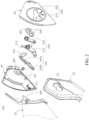
- FIG. 1 is a side view of a helmet including a chin guard pivoting mechanism according to an embodiment of the present disclosure
- FIG. 2 is an exploded perspective view of the chin guard pivoting mechanism according to an embodiment of the present disclosure.
- the chin guard pivoting mechanism 100 is provided in a helmet including a helmet body 10, a chin guard 20 pivotably coupled to the helmet body 10 and a shield 30 pivotably coupled to the helmet body 10, and when the chin guard 20 pivots from the front side of a wearer's chin to a first predetermined angle with respect to the helmet body 10, the shield 30 pivots upward, and when the chin guard 20 pivots to a second predetermined angle that is larger than the first predetermined angle with respect to the helmet body 10, the shield 30 pivots downward, or when the chin guard 20 pivots from the front side of the wearer's chin to the first predetermined angle with respect to the helmet body 10, the shield 30 pivots upward, and when the shield 30 pivots downward, the chin guard 20 pivots to the second predetermined angle with respect to the helmet body 10.
- the helmet body 10 plays a role in protecting the wearer's head.
- the helmet body 10 may be made of a shock absorbing material.
- the helmet body 10 may include an outer shell of hard synthetic resin and having high strength, and an absorber disposed in the outer shell, made of an expanded polystyrene (EPS) foam and having proper strength and elasticity.
- EPS expanded polystyrene
- a pad may be present inside the absorber to improve a snug fit.
- the chin guard 20 plays a role in protecting the wearer's chin, and may be extended in an arc shape as a whole so that it is disposed in front of the wearer's chin.
- the chin guard 20 is, at two ends, rotatably coupled to two sides (for example, a ratchet 40) of the helmet body 10, and is pivotable from a first predetermined position to a third predetermined position.
- the first predetermined position may refer to a position (Full Face Mode) when the chin guard 20 is disposed in front of the wearer's chin (see FIG.
- the second predetermined position may refer to a position (Wearing Mode) when the chin guard 20 is disposed above the helmet body 10 (see FIG. 6A ), and the third predetermined position may refer to a position (Open Face Mode) when the chin guard 20 is disposed at the rear of the helmet body 10 (see FIG. 7A ).
- the shield 30 plays a role in opening and closing a front open portion of the helmet body 10, and is pivotably coupled to the two sides (for example, the ratchet 40) of the helmet body 10, so that the shield 30 is rotatable around the helmet body 10 and pivotable from a first position to a second position.
- the first position may refer to a position in which the shield 30 closes the open portion (see FIG. 3A )
- the second position may refer to a position in which the shield 30 opens the open portion (see FIG. 4A ).
- the chin guard 20 and the shield 30 pivot in tandem by the chin guard pivoting mechanism 100 according to this embodiment, and hereinafter, the chin guard pivoting mechanism 100 will be described in detail.
- the shield 30 may also pivot upward and the open portion may be opened. That is, when the chin guard 20 pivots by the first predetermined angle A from the first predetermined position (Full Face Mode), the shield 30 may pivot from the first position (the closed position of the open portion) to the second position (the open position of the open portion).
- the first predetermined angle A of the chin guard 20 is not limited to a particular angle, but may be, for example, between 15° and 35°.
- the shield 30 may stay in place, not pivoting. That is, while the chin guard 20 pivots to the second predetermined position (Wearing Mode), the shield 30 may be kept in the second position (the open position of the open portion).
- the third predetermined angle C of the chin guard 20 is not limited to a particular angle, but may be, for example, between 140° and 160°.
- the shield 30 may pivot downward and the open portion may be closed. That is, when the chin guard 20 pivots to the third predetermined position (Open Face Mode), the shield 30 may pivot to the first position (the closed position of the open portion).
- the second predetermined angle B of the chin guard 20 is not limited to a particular angle, but may be, for example, between 190° and 210°.
- the chin guard 20 when the chin guard 20 pivots, the shield 30 does not necessarily pivot, and when the shield 30 pivots downward to close the open portion, the chin guard 20 may pivot to the second predetermined angle B with respect to the helmet body 10. That is, when the shield 30 pivots from the second position (the open position of the open portion) to the first position (the closed position of the open portion), the chin guard 20 may pivot to the third predetermined position (Open Face Mode).
- the shield 30 pivots, and when the chin guard 20 is in the second predetermined position (Wearing Mode, see FIG. 6A ), the shield 30 is in the second position (the open position of the open portion), so it is easy for the wearer to wear the helmet.
- the chin guard 20 and the shield 30 pivot in tandem, when the chin guard 20 is disposed above and the shield 30 pivots downward (when the shield 30 pivots from the second position (the open position of the open portion) to the first position (the closed position of the open portion) (see FIGS. 6A to 7A )), the chin guard 20 may automatically pivot to the third predetermined position (Open Face Mode) at the rear of the helmet body 10.
- the chin guard pivoting mechanism 100 may be included in, for example, the ratchet 40, and basically, may include a link 200 and an arm 230.
- the link 200 may be, at one side, coupled to the chin guard 20, and the arm 230 may, at one side, support the shield 30 to pivot the shield 30. That is, the link 200 may be coupled to the chin guard 20, and the arm 230 may support the shield 30, and in this instance, the link 200 and the arm 230 may pivot in tandem, and accordingly the chin guard 20 and the shield 30 may pivot in tandem.
- the link 200 may include a first link 210 and a second link 220.
- the end of the chin guard 20 is coupled to one side of the first link 210 and one side of the second link 220 at the same time.
- one side of the first link 210 and one side of the second link 220 are coupled to a connection portion 250 having two connection holes 253, one side of the first link 210 and one side of the second link 220 may be connected to each other.
- the connection portion 250 is coupled to a fixing portion 25 at the end of the chin guard 20, as a result, one side of the first link 210 and one side of the second link 220 may be coupled to the chin guard 20 at the same time.
- first link 210 pivots around a first rotation axis 211 of the ratchet 40
- second link 220 pivots around a second rotation axis 221 (different from the first rotation axis 211) of the ratchet 40.
- first link 210 and the second link 220 may pivot in tandem.
- the arm 230 may have, on one surface, a sliding portion 240 recessed along the lengthwise direction, and a coupling portion 213 that protrudes from the end of the first link 210 may be inserted into the sliding portion 240 of the arm 230 and slide along the sliding portion 240.
- the first link 210 may pivot around the first rotation axis 211, and the coupling portion 213 of the first link 210 may slide along the sliding portion 240.
- the sliding portion 240 may include a first sliding portion 240a and a second sliding portion 240b.
- the first sliding portion 240a is extended in an arc shape
- the second sliding portion 240b is extended from the end of the first sliding portion 240a in an arc shape.
- the center of the arc of the first sliding portion 240a and the center of the arc of the second sliding portion 240b are different from each other. Accordingly, a point at which the first sliding portion 240a and the second sliding portion 240b meet may have a bent shape.
- the coupling portion 213 of the first link 210 may slide along the first sliding portion 240a, then slide along the second sliding portion 240b, and finally, slide along the first sliding portion 240a again.
- a support portion 300 may be disposed above one side of the arm 230.
- the support portion 300 may be coupled to the shield 30 and pivot by the guidance of the ratchet 40. Accordingly, when the arm 230 pivots, the arm 230 may press the support portion 300, and the support portion 300 and the shield 30 may pivot.
- the arm 230 is provided with the other side (different from one side supporting the support portion 300), which is configured to slide along a pivoting portion 260 (disposed in the ratchet 40) extended in an arc shape, such that the arm 230 rotates as the other side slides in the pivoting portion 260. That is, the arm 230 may pivot in the vertical direction along the pivoting portion 260 extended in an arc shape.
- first link 210 The operation relationship of the first link 210, the second link 220 and the arm 230 will be described in detail below.
- the coupling portion 213 of the first link 210 may slide along the first sliding portion 240a of the arm 230.
- the chin guard 20 pivots in one direction (the clockwise direction), the first link 210 and the second link 220 coupled to the chin guard 20 pivot in the other direction (the counterclockwise direction), and as the coupling portion 213 of the first link 210 slides along the first sliding portion 240a of the arm 230, the arm 230 pivots in one direction (the clockwise direction), and the shield 30 supported on the arm 230 pivots upward (in one direction).
- the shield 30 may pivot from the first position (the closed position of the open portion) to the second position (the open position of the open portion).
- the coupling portion 213 of the first link 210 may slide along the second sliding portion 240b of the arm 230.
- the first link 210 and the second link 220 coupled to the chin guard 20 pivot in the other direction (the counterclockwise direction)
- the coupling portion 213 of the first link 210 slides along the second sliding portion 240b of the arm 230 (see FIG. 5B ).
- the chin guard 20 additionally pivots in one direction (the clockwise direction)
- the first link 210 and the second link 220 coupled to the chin guard 20 pivot in one direction (the clockwise direction) and the other direction (the counterclockwise direction), respectively
- the coupling portion 213 of the first link 210 slides along the second sliding portion 240b of the arm 230 (see FIG. 6B ).
- the coupling portion 213 of the first link 210 slides from one end (an end connected to the first sliding portion 240a) of the second sliding portion 240b of the arm 230 to the other end (see FIG. 5B ), and then slides from the other end of the second sliding portion 240b to one end (see FIG. 6B ).
- the radius of curvature of the second sliding portion 240b may corresponds to the distance between the coupling portion 213 and the first rotation axis 211. Accordingly, while the coupling portion 213 of the first link 210 moves along the two ends of the second sliding portion 240b, the arm 230 does not pivot, and accordingly the shield 30 supported on the arm 230 does not pivot, either. In the end, while the chin guard 20 pivots to the second predetermined position (Wearing Mode), the shield 30 may be kept in the second position (the open position of the open portion).
- the coupling portion 213 of the first link 210 may slide along the first sliding portion 240a of the arm 230.
- the first link 210 and the second link 220 coupled to the chin guard 20 pivot in one direction (the clockwise direction) (in this instance, a pivot angle of the second link 220 is smaller than that of the first link 210), and as the coupling portion 213 of the first link 210 slides along the first sliding portion 240a of the arm 230, the arm 230 pivots in the other direction (the counterclockwise direction), and the shield 30 supported on the arm 230 pivots downward (in the other direction).
- the shield 30 may pivot to the first position (the closed position of the open portion).
- the present disclosure is not necessarily limited to the downward pivoting of the shield 30 with the pivoting of the chin guard 20, and may include pivoting of the chin guard 20 with the downward pivoting of the shield 30. That is, when the shield 30 pivots downward and the chin guard 20 pivots to the second predetermined angle B with respect to the helmet body 10, the coupling portion 213 of the first link 210 may slide along the first sliding portion 240a of the arm 230.
- the chin guard 20 coupled to the first link 210 and the second link 220 may pivot in one direction (the clockwise direction).
- the shield 30 pivots from the second position (the open position of the open portion) to the first position (the closed position of the open portion)
- the chin guard 20 may pivot from the second predetermined position (Wearing Mode) to the third predetermined position (Open Face Mode).
- one side of the first link 210 and one side of the second link 220 coupled to the chin guard 20 are reversed by the pivoting of the chin guard 20.
- one side of the first link 210 may be disposed in front of one side of the second link 220 (see FIGS. 3B and 4B ), then disposed above one side of the second link 220 (see FIGS. 5B and 6B ), and subsequently, disposed at the rear of one side of the second link 220 (see FIG. 7B ).
- the ratchet 40 may have a guide hole 500 on the front surface.
- the guide hole 500 may include a first guide hole 510 and a second guide hole 520.
- the first guide hole 510 plays a role in guiding the movement path of one side of the first link 210
- the second guide hole 520 plays a role in guiding the movement path of one side of the second link 220.
- the radius of curvature of the first guide hole 510 may correspond to the distance between one side of the first link 210 and the first rotation axis 211
- the radius of curvature of the second guide hole 520 may correspond to the distance between one side of the second link 220 and the second rotation axis 221.
- the ratchet 40 may include a fastening portion 400 to fix the link 200.
- the fastening portion 400 may be coupled to the link 200 (the first link 210) to prevent arbitrary pivoting of the link 200 (the first link 210). Accordingly, it is possible to prevent arbitrary pivoting of the chin guard 20 coupled to the link 200 (the first link 210) by the fastening portion 400.
- the fastening portion 400 may be separated from the link 200 (the first link 210).
- a first hook portion 410 of the fastening portion 400 may be fastened to a second hook portion 215 of the link 200 (the first link 210) to prevent arbitrary pivoting of the link 200 (the first link 210).
- the link 200 (the first link 210) may pivot, and accordingly, the fastening portion 400 may pivot, and the first hook portion 410 may be separated from the second hook portion 215.
- an elastic force may be applied to the fastening portion 400 in a direction in which the first hook portion 410 is fastened to the second hook portion 215.
- a torsion spring may be coupled to the fastening portion 400.
- the present disclosure provides the chin guard pivoting mechanism for pivoting the chin guard and the shield in tandem.
Landscapes
- Helmets And Other Head Coverings (AREA)
Abstract
Description
- The present disclosure relates to a chin guard pivoting mechanism.
- In general, it is mandatory to wear a helmet while driving a two wheeled vehicle with high speed to protect the wearer's head. The helmet has a front open portion to ensure the wearer's frontal field of view. Additionally, the helmet may include a shield that can selectively open and close the open portion to keep out wind, dust, etc. while driving.
- Meanwhile, the helmet according to the prior art includes a chin guard to protect the wearer's chin as disclosed by the patent literature of the related literatures as described below.
- (Patent Literature 1)
KR10-2014-0001141 A - An aspect of the present disclosure is directed to a chin guard pivoting mechanism for pivoting a chin guard and a shield in tandem.
- A chin guard pivoting mechanism according to an embodiment of the present disclosure is provided in a helmet including a helmet body, a chin guard pivotally coupled to the helmet body and a shield pivotally coupled to the helmet body, and upon pivoting of the chin guard from a front side of a wearer's chin to a first predetermined angle with respect to the helmet body, the shield pivots upward, and upon pivoting of the chin guard to a second predetermined angle which is larger than the first predetermined angle with respect to the helmet body, the shield pivots downward, or upon pivoting of the chin guard from the front side of the wearer's chin to the first predetermined angle with respect to the helmet body, the shield pivots upward, and upon downward pivoting of the shield, the chin guard pivots to the second predetermined angle with respect to the helmet body.
- Additionally, in the chin guard pivoting mechanism according to an embodiment of the present disclosure, upon pivoting of the chin guard from the first predetermined angle to a third predetermined angle between the first predetermined angle and the second predetermined angle with respect to the helmet body, the shield does not pivot.
- Additionally, in the chin guard pivoting mechanism according to an embodiment of the present disclosure, the chin guard pivoting mechanism includes a link having one side coupled to the chin guard, and an arm which pivots the shield at one side, and the link and the arm pivot in tandem.
- Additionally, in the chin guard pivoting mechanism according to an embodiment of the present disclosure, the link includes a first link and a second link, the chin guard is coupled to one side of the first link and one side of the second link, and the other side of the first link pivots around a first rotation axis, and the other side of the second link pivots around a second rotation axis.
- Additionally, in the chin guard pivoting mechanism according to an embodiment of the present disclosure, upon pivoting of the chin guard from the front side of the wearer's chin with respect to the helmet body, one side of the first link is disposed in front of one side of the second link, then disposed above one side of the second link, and subsequently disposed at rear of one side of the second link.
- Additionally, in the chin guard pivoting mechanism according to an embodiment of the present disclosure, the arm has a sliding portion along a lengthwise direction, and upon the pivoting of the chin guard, a coupling portion of the first link is slidable along the sliding portion.
- Additionally, in the chin guard pivoting mechanism according to an embodiment of the present disclosure, the sliding portion includes a first sliding portion extended in an arc shape, and a second sliding portion extended from an end of the first sliding portion in an arc shape.
- Additionally, in the chin guard pivoting mechanism according to an embodiment of the present disclosure, upon the upward pivoting of the shield with the pivoting of the chin guard from the front side of the wearer's chin to the first predetermined angle with respect to the helmet body, the coupling portion slides along the first sliding portion, and upon the downward pivoting of the shield with the pivoting of the chin guard to the second predetermined angle with respect to the helmet body, or upon the pivoting of the chin guard to the second predetermined angle with respect to the helmet body with the downward pivoting of the shield, the coupling portion slides along the first sliding portion.
- Additionally, in the chin guard pivoting mechanism according to an embodiment of the present disclosure, upon pivoting of the chin guard from the first predetermined angle to a third predetermined angle between the first predetermined angle and the second predetermined angle with respect to the helmet body, and not pivoting of the shield, the coupling portion slides along the second sliding portion.
- Additionally, in the chin guard pivoting mechanism according to an embodiment of the present disclosure, a radius of curvature of the second sliding portion corresponds to a distance between the coupling portion and the first rotation axis.
- Additionally, in the chin guard pivoting mechanism according to an embodiment of the present disclosure, the arm is provided with the other side, which is configured to slide along a pivoting portion extended in an arc shape, such that the arm rotates as the other side slides in the pivoting portion.
- Additionally, the chin guard pivoting mechanism according to an embodiment of the present disclosure includes a fastening portion which is coupled to the link, and is separated from the link upon the pivoting of the chin guard with respect to the helmet body.
- Additionally, in the chin guard pivoting mechanism according to an embodiment of the present disclosure, a first hook portion of the fastening portion is fastened to a second hook portion of the link, and upon the pivoting of the chin guard with respect to the helmet body, the link pivots and accordingly the fastening portion pivots, and the first hook portion is separated from the second hook portion.
- Additionally, in the chin guard pivoting mechanism according to an embodiment of the present disclosure, an elastic force is applied to the fastening portion in a direction in which the first hook portion is fastened to the second hook portion.
- The features and advantages of the present disclosure will be apparent from the following detailed description in accordance with the accompanying drawings.
- Prior to the description, it should be understood that the terms or words used in the specification and the appended claims should not be construed as limited to general and dictionary meanings, but rather interpreted based on the meanings and concepts corresponding to the technical spirit of the present disclosure on the basis of the principle that the inventor is allowed to define terms appropriately for the best explanation.
- According to the present disclosure, since the chin guard and the shield pivot in tandem, when the chin guard pivots, the shield pivots, so it is easy for the wearer to wear the helmet.
- In addition, according to the present disclosure, since the chin guard and the shield pivot in tandem, when the chin guard is disposed above and the shield pivots downward, the chin guard may automatically pivot to the rear side of the helmet body.
-
-
FIG. 1 is a side view of a helmet including a chin guard pivoting mechanism according to an embodiment of the present disclosure. -
FIG. 2 is an exploded perspective view of a chin guard pivoting mechanism according to an embodiment of the present disclosure. -
FIGS. 3 to 7 are side views showing an operation process of a helmet including a chin guard pivoting mechanism according to an embodiment of the present disclosure and an operation process of the chin guard pivoting mechanism. - The objectives, particular advantages and new features of the present disclosure will be apparent from the following detailed description and exemplary embodiments in association with the accompanying drawings. In affixing the reference numbers to the elements of each drawing in the present disclosure, it should be noted that identical elements are given as identical numbers as possible although they are depicted in different drawings. Additionally, the terms such as "first", "second" or the like are used to distinguish one element from another, and the elements are not limited by the terms. Hereinafter, in describing the present disclosure, when it is determined that a certain description of related known technology may unnecessarily obscure the subject matter of the present disclosure, the detailed description is omitted.
- Hereinafter, exemplary embodiments of the present disclosure will be described in detail with reference to the accompanying drawings.
-
FIG. 1 is a side view of a helmet including a chin guard pivoting mechanism according to an embodiment of the present disclosure, andFIG. 2 is an exploded perspective view of the chin guard pivoting mechanism according to an embodiment of the present disclosure. - As shown in
FIGS. 1 and2 , the chinguard pivoting mechanism 100 according to this embodiment is provided in a helmet including ahelmet body 10, achin guard 20 pivotably coupled to thehelmet body 10 and ashield 30 pivotably coupled to thehelmet body 10, and when thechin guard 20 pivots from the front side of a wearer's chin to a first predetermined angle with respect to thehelmet body 10, theshield 30 pivots upward, and when the chin guard 20 pivots to a second predetermined angle that is larger than the first predetermined angle with respect to thehelmet body 10, theshield 30 pivots downward, or when the chin guard 20 pivots from the front side of the wearer's chin to the first predetermined angle with respect to thehelmet body 10, theshield 30 pivots upward, and when theshield 30 pivots downward, the chin guard 20 pivots to the second predetermined angle with respect to thehelmet body 10. - Basically, the
helmet body 10 plays a role in protecting the wearer's head. Thehelmet body 10 may be made of a shock absorbing material. For example, thehelmet body 10 may include an outer shell of hard synthetic resin and having high strength, and an absorber disposed in the outer shell, made of an expanded polystyrene (EPS) foam and having proper strength and elasticity. A pad may be present inside the absorber to improve a snug fit. - Additionally, the
chin guard 20 plays a role in protecting the wearer's chin, and may be extended in an arc shape as a whole so that it is disposed in front of the wearer's chin. In this instance, thechin guard 20 is, at two ends, rotatably coupled to two sides (for example, a ratchet 40) of thehelmet body 10, and is pivotable from a first predetermined position to a third predetermined position. For example, the first predetermined position may refer to a position (Full Face Mode) when thechin guard 20 is disposed in front of the wearer's chin (seeFIG. 3A ), the second predetermined position may refer to a position (Wearing Mode) when thechin guard 20 is disposed above the helmet body 10 (seeFIG. 6A ), and the third predetermined position may refer to a position (Open Face Mode) when thechin guard 20 is disposed at the rear of the helmet body 10 (seeFIG. 7A ). - Additionally, the
shield 30 plays a role in opening and closing a front open portion of thehelmet body 10, and is pivotably coupled to the two sides (for example, the ratchet 40) of thehelmet body 10, so that theshield 30 is rotatable around thehelmet body 10 and pivotable from a first position to a second position. For example, the first position may refer to a position in which theshield 30 closes the open portion (seeFIG. 3A ), and the second position may refer to a position in which theshield 30 opens the open portion (seeFIG. 4A ). - The
chin guard 20 and theshield 30 pivot in tandem by the chinguard pivoting mechanism 100 according to this embodiment, and hereinafter, the chinguard pivoting mechanism 100 will be described in detail. - As shown in
FIGS. 3A to 4A , when the chin guard 20 pivots from the front side of the wearer's chin to the first predetermined angle A with respect to thehelmet body 10, theshield 30 may also pivot upward and the open portion may be opened. That is, when the chin guard 20 pivots by the first predetermined angle A from the first predetermined position (Full Face Mode), theshield 30 may pivot from the first position (the closed position of the open portion) to the second position (the open position of the open portion). In this instance, the first predetermined angle A of thechin guard 20 is not limited to a particular angle, but may be, for example, between 15° and 35°. - Subsequently, as shown in
FIGS. 5A to 6A , when the chin guard 20 pivots from the first predetermined angle A to a third predetermined angle C that is larger than the first predetermined angle A with respect to thehelmet body 10, theshield 30 may stay in place, not pivoting. That is, while the chin guard 20 pivots to the second predetermined position (Wearing Mode), theshield 30 may be kept in the second position (the open position of the open portion). In this instance, the third predetermined angle C of thechin guard 20 is not limited to a particular angle, but may be, for example, between 140° and 160°. - Subsequently, as shown in
FIG. 7A , when thechin guard 20 pivots to the second predetermined angle B that is larger than the first and third predetermined angles A, C with respect to thehelmet body 10, theshield 30 may pivot downward and the open portion may be closed. That is, when thechin guard 20 pivots to the third predetermined position (Open Face Mode), theshield 30 may pivot to the first position (the closed position of the open portion). In this instance, the second predetermined angle B of thechin guard 20 is not limited to a particular angle, but may be, for example, between 190° and 210°. - However, when the
chin guard 20 pivots, theshield 30 does not necessarily pivot, and when theshield 30 pivots downward to close the open portion, thechin guard 20 may pivot to the second predetermined angle B with respect to thehelmet body 10. That is, when theshield 30 pivots from the second position (the open position of the open portion) to the first position (the closed position of the open portion), thechin guard 20 may pivot to the third predetermined position (Open Face Mode). - In the end, since the
chin guard 20 and theshield 30 pivot in tandem, when thechin guard 20 pivots, theshield 30 pivots, and when thechin guard 20 is in the second predetermined position (Wearing Mode, seeFIG. 6A ), theshield 30 is in the second position (the open position of the open portion), so it is easy for the wearer to wear the helmet. - Additionally, since the
chin guard 20 and theshield 30 pivot in tandem, when thechin guard 20 is disposed above and theshield 30 pivots downward (when theshield 30 pivots from the second position (the open position of the open portion) to the first position (the closed position of the open portion) (seeFIGS. 6A to 7A )), thechin guard 20 may automatically pivot to the third predetermined position (Open Face Mode) at the rear of thehelmet body 10. - As shown in
FIG. 2 , the chinguard pivoting mechanism 100 may be included in, for example, theratchet 40, and basically, may include alink 200 and anarm 230. Specifically, thelink 200 may be, at one side, coupled to thechin guard 20, and thearm 230 may, at one side, support theshield 30 to pivot theshield 30. That is, thelink 200 may be coupled to thechin guard 20, and thearm 230 may support theshield 30, and in this instance, thelink 200 and thearm 230 may pivot in tandem, and accordingly thechin guard 20 and theshield 30 may pivot in tandem. - More specifically, the
link 200 may include afirst link 210 and asecond link 220. Here, the end of thechin guard 20 is coupled to one side of thefirst link 210 and one side of thesecond link 220 at the same time. For example, when one side of thefirst link 210 and one side of thesecond link 220 are coupled to aconnection portion 250 having twoconnection holes 253, one side of thefirst link 210 and one side of thesecond link 220 may be connected to each other. Additionally, when theconnection portion 250 is coupled to a fixingportion 25 at the end of thechin guard 20, as a result, one side of thefirst link 210 and one side of thesecond link 220 may be coupled to thechin guard 20 at the same time. - On the other hand, the other side of the
first link 210 pivots around afirst rotation axis 211 of theratchet 40, and the other side of thesecond link 220 pivots around a second rotation axis 221 (different from the first rotation axis 211) of theratchet 40. In this instance, since one side of thefirst link 210 and one side of thesecond link 220 are coupled to the end of thechin guard 20 at the same time, when thechin guard 20 pivots, thefirst link 210 and thesecond link 220 may pivot in tandem. - Additionally, the
arm 230 may have, on one surface, a slidingportion 240 recessed along the lengthwise direction, and acoupling portion 213 that protrudes from the end of thefirst link 210 may be inserted into the slidingportion 240 of thearm 230 and slide along the slidingportion 240. Specifically, when thechin guard 20 pivots, thefirst link 210 may pivot around thefirst rotation axis 211, and thecoupling portion 213 of thefirst link 210 may slide along the slidingportion 240. More specifically, the slidingportion 240 may include a first slidingportion 240a and a second slidingportion 240b. Here, the first slidingportion 240a is extended in an arc shape, and the second slidingportion 240b is extended from the end of the first slidingportion 240a in an arc shape. In this instance, the center of the arc of the first slidingportion 240a and the center of the arc of the second slidingportion 240b are different from each other. Accordingly, a point at which the first slidingportion 240a and the second slidingportion 240b meet may have a bent shape. In the end, when thechin guard 20 pivots, thecoupling portion 213 of thefirst link 210 may slide along the first slidingportion 240a, then slide along the second slidingportion 240b, and finally, slide along the first slidingportion 240a again. - Meanwhile, a
support portion 300 may be disposed above one side of thearm 230. In this instance, thesupport portion 300 may be coupled to theshield 30 and pivot by the guidance of theratchet 40. Accordingly, when thearm 230 pivots, thearm 230 may press thesupport portion 300, and thesupport portion 300 and theshield 30 may pivot. Additionally, thearm 230 is provided with the other side (different from one side supporting the support portion 300), which is configured to slide along a pivoting portion 260 (disposed in the ratchet 40) extended in an arc shape, such that thearm 230 rotates as the other side slides in the pivotingportion 260. That is, thearm 230 may pivot in the vertical direction along the pivotingportion 260 extended in an arc shape. - The operation relationship of the
first link 210, thesecond link 220 and thearm 230 will be described in detail below. - As shown in
FIGS. 3 and4 , when thechin guard 20 pivots from the front side of the wearer's chin to the first predetermined angle A with respect to thehelmet body 10 and theshield 30 pivots upward, thecoupling portion 213 of thefirst link 210 may slide along the first slidingportion 240a of thearm 230. Specifically, when thechin guard 20 pivots in one direction (the clockwise direction), thefirst link 210 and thesecond link 220 coupled to thechin guard 20 pivot in the other direction (the counterclockwise direction), and as thecoupling portion 213 of thefirst link 210 slides along the first slidingportion 240a of thearm 230, thearm 230 pivots in one direction (the clockwise direction), and theshield 30 supported on thearm 230 pivots upward (in one direction). In the end, when thechin guard 20 pivots by the first predetermined angle A from the first predetermined position (Full Face Mode), theshield 30 may pivot from the first position (the closed position of the open portion) to the second position (the open position of the open portion). - As shown in
FIGS. 5 and6 , when thechin guard 20 pivots from the first predetermined angle A to the third predetermined angle C with respect to thehelmet body 10 and theshield 30 does not pivot, thecoupling portion 213 of thefirst link 210 may slide along the second slidingportion 240b of thearm 230. Specifically, when thechin guard 20 pivots in one direction (the clockwise direction), thefirst link 210 and thesecond link 220 coupled to thechin guard 20 pivot in the other direction (the counterclockwise direction), and thecoupling portion 213 of thefirst link 210 slides along the second slidingportion 240b of the arm 230 (seeFIG. 5B ). Subsequently, when thechin guard 20 additionally pivots in one direction (the clockwise direction), thefirst link 210 and thesecond link 220 coupled to thechin guard 20 pivot in one direction (the clockwise direction) and the other direction (the counterclockwise direction), respectively, and thecoupling portion 213 of thefirst link 210 slides along the second slidingportion 240b of the arm 230 (seeFIG. 6B ). In the end, thecoupling portion 213 of thefirst link 210 slides from one end (an end connected to the first slidingportion 240a) of the second slidingportion 240b of thearm 230 to the other end (seeFIG. 5B ), and then slides from the other end of the second slidingportion 240b to one end (seeFIG. 6B ). In this instance, the radius of curvature of the second slidingportion 240b may corresponds to the distance between thecoupling portion 213 and thefirst rotation axis 211. Accordingly, while thecoupling portion 213 of thefirst link 210 moves along the two ends of the second slidingportion 240b, thearm 230 does not pivot, and accordingly theshield 30 supported on thearm 230 does not pivot, either. In the end, while thechin guard 20 pivots to the second predetermined position (Wearing Mode), theshield 30 may be kept in the second position (the open position of the open portion). - As shown in
FIG. 7 , when thechin guard 20 pivots from the third predetermined angle C to the second predetermined angle B with respect to thehelmet body 10 and theshield 30 pivots downward, thecoupling portion 213 of thefirst link 210 may slide along the first slidingportion 240a of thearm 230. Specifically, when thechin guard 20 pivots in one direction (the clockwise direction), thefirst link 210 and thesecond link 220 coupled to thechin guard 20 pivot in one direction (the clockwise direction) (in this instance, a pivot angle of thesecond link 220 is smaller than that of the first link 210), and as thecoupling portion 213 of thefirst link 210 slides along the first slidingportion 240a of thearm 230, thearm 230 pivots in the other direction (the counterclockwise direction), and theshield 30 supported on thearm 230 pivots downward (in the other direction). In the end, when thechin guard 20 pivots from the second predetermined position (Wearing Mode) to the third predetermined position (Open Face Mode), theshield 30 may pivot to the first position (the closed position of the open portion). - However, the present disclosure is not necessarily limited to the downward pivoting of the
shield 30 with the pivoting of thechin guard 20, and may include pivoting of thechin guard 20 with the downward pivoting of theshield 30. That is, when theshield 30 pivots downward and thechin guard 20 pivots to the second predetermined angle B with respect to thehelmet body 10, thecoupling portion 213 of thefirst link 210 may slide along the first slidingportion 240a of thearm 230. Specifically, when theshield 30 pivots in the other direction (the counterclockwise direction), thearm 230 supporting theshield 30 pivots in the other direction (the counterclockwise direction), and as thecoupling portion 213 of thefirst link 210 slides along the first slidingportion 240a of thearm 230, thefirst link 210 and thesecond link 220 pivot in one direction (the clockwise direction), and accordingly thechin guard 20 coupled to thefirst link 210 and thesecond link 220 may pivot in one direction (the clockwise direction). In the end, when theshield 30 pivots from the second position (the open position of the open portion) to the first position (the closed position of the open portion), thechin guard 20 may pivot from the second predetermined position (Wearing Mode) to the third predetermined position (Open Face Mode). - Overall, one side of the
first link 210 and one side of thesecond link 220 coupled to thechin guard 20 are reversed by the pivoting of thechin guard 20. Specifically, when thechin guard 20 pivots from the front side of the wearer's chin with respect to thehelmet body 10, one side of thefirst link 210 may be disposed in front of one side of the second link 220 (seeFIGS. 3B and4B ), then disposed above one side of the second link 220 (seeFIGS. 5B and6B ), and subsequently, disposed at the rear of one side of the second link 220 (seeFIG. 7B ). - Meanwhile, to guide the movement path of one side of the
first link 210 and one side of thesecond link 220, theratchet 40 may have aguide hole 500 on the front surface. Specifically, theguide hole 500 may include afirst guide hole 510 and asecond guide hole 520. Here, thefirst guide hole 510 plays a role in guiding the movement path of one side of thefirst link 210, and thesecond guide hole 520 plays a role in guiding the movement path of one side of thesecond link 220. Accordingly, the radius of curvature of thefirst guide hole 510 may correspond to the distance between one side of thefirst link 210 and thefirst rotation axis 211, and the radius of curvature of thesecond guide hole 520 may correspond to the distance between one side of thesecond link 220 and thesecond rotation axis 221. - In addition, the
ratchet 40 may include afastening portion 400 to fix thelink 200. Here, when thechin guard 20 is disposed in front of the wearer's chin or at the rear of thehelmet body 10, thefastening portion 400 may be coupled to the link 200 (the first link 210) to prevent arbitrary pivoting of the link 200 (the first link 210). Accordingly, it is possible to prevent arbitrary pivoting of thechin guard 20 coupled to the link 200 (the first link 210) by thefastening portion 400. However, when the wearer manipulates thechin guard 20 to pivot thechin guard 20 with respect to thehelmet body 10, thefastening portion 400 may be separated from the link 200 (the first link 210). - Specifically, when the
chin guard 20 is disposed in front of the wearer's chin or at the rear of thehelmet body 10, afirst hook portion 410 of thefastening portion 400 may be fastened to asecond hook portion 215 of the link 200 (the first link 210) to prevent arbitrary pivoting of the link 200 (the first link 210). However, when the wearer manipulates thechin guard 20 to pivot thechin guard 20 with respect to thehelmet body 10, the link 200 (the first link 210) may pivot, and accordingly, thefastening portion 400 may pivot, and thefirst hook portion 410 may be separated from thesecond hook portion 215. In this instance, an elastic force may be applied to thefastening portion 400 in a direction in which thefirst hook portion 410 is fastened to thesecond hook portion 215. For example, a torsion spring may be coupled to thefastening portion 400. - While the present disclosure has been hereinabove described in detail through the specific embodiments, this is provided to describe the present disclosure in detail, and the present disclosure is not limited thereto, and it is obvious that modifications or changes may be made thereto by those having ordinary skill in the art within the technical spirit of the present disclosure.
- Such modifications and changes of the present disclosure fall in the scope of the present disclosure, and the scope of protection of the present disclosure will be apparent by the appended claims.
-
10: Helmet body 20: Chin guard 30: Shield 40: Ratchet 100: Chin guard pivoting mechanism 200: Link 210: First link 211: First rotation axis 213: Coupling portion 215: Second hook portion 220: Second link 221: Second rotation axis 230: Arm 240: Sliding portion 240a: First sliding portion 240b: Second sliding portion 250: Connection portion 260: Pivoting portion 300: Support portion 400: Fastening portion 410: First hook portion 500: Guide hole 510: First guide hole 520: Second guide hole - The present disclosure provides the chin guard pivoting mechanism for pivoting the chin guard and the shield in tandem.
Claims (14)
- A chin guard pivoting mechanism which is provided in a helmet comprising a helmet body, a chin guard pivotally coupled to the helmet body and a shield pivotally coupled to the helmet body,wherein upon pivoting of the chin guard from a front side of a wearer's chin to a first predetermined angle with respect to the helmet body, the shield pivots upward, and upon pivoting of the chin guard to a second predetermined angle which is larger than the first predetermined angle with respect to the helmet body, the shield pivots downward, orwherein upon pivoting of the chin guard from the front side of the wearer's chin to the first predetermined angle with respect to the helmet body, the shield pivots upward, and upon downward pivoting of the shield, the chin guard pivots to the second predetermined angle with respect to the helmet body.
- The chin guard pivoting mechanism according to claim 1, wherein upon pivoting of the chin guard from the first predetermined angle to a third predetermined angle between the first predetermined angle and the second predetermined angle with respect to the helmet body, the shield does not pivot.
- The chin guard pivoting mechanism according to claim 1, wherein the chin guard pivoting mechanism comprises:a link having one side coupled to the chin guard; andan arm which pivots the shield at one side, andwherein the link and the arm pivot in tandem.
- The chin guard pivoting mechanism according to claim 3, wherein the link includes a first link and a second link,wherein the chin guard is coupled to one side of the first link and one side of the second link, andwherein the other side of the first link pivots around a first rotation axis, and the other side of the second link pivots around a second rotation axis.
- The chin guard pivoting mechanism according to claim 4, wherein upon pivoting of the chin guard from the front side of the wearer's chin with respect to the helmet body, one side of the first link is disposed in front of one side of the second link, then disposed above one side of the second link, and subsequently disposed at rear of one side of the second link.
- The chin guard pivoting mechanism according to claim 4, wherein the arm has a sliding portion along a lengthwise direction, and
wherein upon the pivoting of the chin guard, a coupling portion of the first link is slidable along the sliding portion. - The chin guard pivoting mechanism according to claim 6, wherein the sliding portion includes:a first sliding portion extended in an arc shape; anda second sliding portion extended from an end of the first sliding portion in an arc shape.
- The chin guard pivoting mechanism according to claim 7, wherein upon the upward pivoting of the shield with the pivoting of the chin guard from the front side of the wearer's chin to the first predetermined angle with respect to the helmet body, the coupling portion slides along the first sliding portion, and
wherein upon the downward pivoting of the shield with the pivoting of the chin guard to the second predetermined angle with respect to the helmet body, or upon the pivoting of the chin guard to the second predetermined angle with respect to the helmet body with the downward pivoting of the shield, the coupling portion slides along the first sliding portion. - The chin guard pivoting mechanism according to claim 8, wherein upon pivoting of the chin guard from the first predetermined angle to a third predetermined angle between the first predetermined angle and the second predetermined angle with respect to the helmet body, and not pivoting of the shield, the coupling portion slides along the second sliding portion.
- The chin guard pivoting mechanism according to claim 9, wherein a radius of curvature of the second sliding portion corresponds to a distance between the coupling portion and the first rotation axis.
- The chin guard pivoting mechanism according to claim 3, wherein the arm is provided with the other side, which is configured to slide along a pivoting portion extended in an arc shape, such that the arm rotates as the other side slides in the pivoting portion.
- The chin guard pivoting mechanism according to claim 3, wherein comprises a fastening portion which is coupled to the link, and is separated from the link upon the pivoting of the chin guard with respect to the helmet body.
- The chin guard pivoting mechanism according to claim 12, wherein a first hook portion of the fastening portion is fastened to a second hook portion of the link, and upon the pivoting of the chin guard with respect to the helmet body, the link pivots and accordingly the fastening portion pivots, and the first hook portion is separated from the second hook portion.
- The chin guard pivoting mechanism according to claim 13, wherein an elastic force is applied to the fastening portion in a direction in which the first hook portion is fastened to the second hook portion.
Applications Claiming Priority (2)
| Application Number | Priority Date | Filing Date | Title |
|---|---|---|---|
| KR1020210018412A KR102433223B1 (en) | 2021-02-09 | 2021-02-09 | Chin guard rotation mechanism |
| PCT/KR2021/017166 WO2022173097A1 (en) | 2021-02-09 | 2021-11-22 | Chin guard pivoting mechanism |
Publications (2)
| Publication Number | Publication Date |
|---|---|
| EP4268657A1 true EP4268657A1 (en) | 2023-11-01 |
| EP4268657A4 EP4268657A4 (en) | 2024-06-12 |
Family
ID=82837555
Family Applications (1)
| Application Number | Title | Priority Date | Filing Date |
|---|---|---|---|
| EP21925917.3A Pending EP4268657A4 (en) | 2021-02-09 | 2021-11-22 | Chin guard pivoting mechanism |
Country Status (4)
| Country | Link |
|---|---|
| US (1) | US20240081463A1 (en) |
| EP (1) | EP4268657A4 (en) |
| KR (1) | KR102433223B1 (en) |
| WO (1) | WO2022173097A1 (en) |
Family Cites Families (8)
| Publication number | Priority date | Publication date | Assignee | Title |
|---|---|---|---|---|
| KR100341452B1 (en) * | 1999-12-06 | 2002-06-21 | 홍완기 | Jaw Protecting Apparatus of Helmet |
| FR2886521B1 (en) * | 2005-06-03 | 2007-09-07 | Cbm Distrib Entpr Unipersonnel | HELMET FOR MOBILE VISOR PROTECTION |
| KR100875460B1 (en) * | 2007-10-18 | 2008-12-22 | 주식회사 홍진에이치제이씨 | Chin protection bar opening/closing mechanism for safety helmet |
| JP5358722B1 (en) | 2012-06-26 | 2013-12-04 | 株式会社アライヘルメット | helmet |
| FR3023681B1 (en) * | 2014-07-21 | 2016-08-19 | Shark | MOBILE CHAIN PROTECTION HELMET WITH AUTOMATIC SCREEN LIFTING MECHANISM |
| ES2673110T3 (en) * | 2014-09-30 | 2018-06-19 | Locatelli S.P.A. | Motorcycle Helmet |
| KR102641350B1 (en) * | 2019-04-11 | 2024-02-27 | 주식회사 기도스포츠 | Chin guard positioning assembly and helmet using the same |
| CN109875177B (en) * | 2019-03-04 | 2024-02-13 | 江门市鹏程头盔有限公司 | Gear constraint type helmet with variable jaw protection structure |
-
2021
- 2021-02-09 KR KR1020210018412A patent/KR102433223B1/en active IP Right Grant
- 2021-11-22 WO PCT/KR2021/017166 patent/WO2022173097A1/en active Application Filing
- 2021-11-22 EP EP21925917.3A patent/EP4268657A4/en active Pending
- 2021-11-22 US US18/263,912 patent/US20240081463A1/en active Pending
Also Published As
| Publication number | Publication date |
|---|---|
| WO2022173097A1 (en) | 2022-08-18 |
| EP4268657A4 (en) | 2024-06-12 |
| KR102433223B1 (en) | 2022-08-18 |
| US20240081463A1 (en) | 2024-03-14 |
Similar Documents
| Publication | Publication Date | Title |
|---|---|---|
| US8918912B2 (en) | Shield coupling assembly and helmet having the same | |
| US11470906B2 (en) | Protective helmet and face shield | |
| JP5305579B2 (en) | Vehicle open roof structure and windbreaker | |
| EP3136899B1 (en) | Ear muff attachment having dual axis of rotation | |
| CN101119655A (en) | Safety eyewear | |
| JP2013503665A (en) | Shoulder mechanism for orthosis | |
| CA2658238A1 (en) | Helmet having a guiding mechanism for a compatible visor and a visor for such a helmet | |
| US11160323B2 (en) | Visor carrier assembly | |
| KR100875460B1 (en) | Chin protection bar opening/closing mechanism for safety helmet | |
| US20110072563A1 (en) | Pin lock device and helmet including same | |
| JP2015045108A (en) | Shield support structure in helmet | |
| US8919858B2 (en) | Assembly of swing type tailgate checker | |
| CN104153666B (en) | Vehicle and the hinge component in the storage railway carriage or compartment for vehicle | |
| EP4268657A1 (en) | Chin guard pivoting mechanism | |
| US20160263753A1 (en) | Scissors | |
| CN106539180A (en) | Jet-propelled helmet structure with built-in sunshading board | |
| EP4321048A1 (en) | Shield rotation controlling means | |
| KR102461899B1 (en) | Rotating body fixing means for helmet | |
| EP4410139A1 (en) | Rotating body fixing means for helmet | |
| KR20230126814A (en) | Helmet | |
| KR102582371B1 (en) | Rotation Mechanism for Chin guard | |
| KR102428292B1 (en) | Chin Guard Spacing Adjustment Means for Helmet | |
| US20240130460A1 (en) | Rotating means for helmet | |
| KR102646629B1 (en) | Rotation mechanism for Helmet | |
| KR102631086B1 (en) | Locking means for Chin guard |
Legal Events
| Date | Code | Title | Description |
|---|---|---|---|
| STAA | Information on the status of an ep patent application or granted ep patent |
Free format text: STATUS: THE INTERNATIONAL PUBLICATION HAS BEEN MADE |
|
| PUAI | Public reference made under article 153(3) epc to a published international application that has entered the european phase |
Free format text: ORIGINAL CODE: 0009012 |
|
| STAA | Information on the status of an ep patent application or granted ep patent |
Free format text: STATUS: REQUEST FOR EXAMINATION WAS MADE |
|
| 17P | Request for examination filed |
Effective date: 20230726 |
|
| AK | Designated contracting states |
Kind code of ref document: A1 Designated state(s): AL AT BE BG CH CY CZ DE DK EE ES FI FR GB GR HR HU IE IS IT LI LT LU LV MC MK MT NL NO PL PT RO RS SE SI SK SM TR |
|
| REG | Reference to a national code |
Ref country code: DE Ref legal event code: R079 Free format text: PREVIOUS MAIN CLASS: A42B0003200000 Ipc: A42B0003320000 |
|
| DAV | Request for validation of the european patent (deleted) | ||
| DAX | Request for extension of the european patent (deleted) | ||
| A4 | Supplementary search report drawn up and despatched |
Effective date: 20240510 |
|
| RIC1 | Information provided on ipc code assigned before grant |
Ipc: A42B 3/32 20060101AFI20240503BHEP |