EP4268637A1 - Atomizer and electronic atomization device - Google Patents
Atomizer and electronic atomization device Download PDFInfo
- Publication number
- EP4268637A1 EP4268637A1 EP21909057.8A EP21909057A EP4268637A1 EP 4268637 A1 EP4268637 A1 EP 4268637A1 EP 21909057 A EP21909057 A EP 21909057A EP 4268637 A1 EP4268637 A1 EP 4268637A1
- Authority
- EP
- European Patent Office
- Prior art keywords
- atomizer
- liquid
- liquid inlet
- insulating layer
- heating
- Prior art date
- Legal status (The legal status is an assumption and is not a legal conclusion. Google has not performed a legal analysis and makes no representation as to the accuracy of the status listed.)
- Pending
Links
- 238000000889 atomisation Methods 0.000 title claims abstract description 76
- 239000007788 liquid Substances 0.000 claims abstract description 172
- 238000010438 heat treatment Methods 0.000 claims abstract description 119
- 229910052751 metal Inorganic materials 0.000 claims description 57
- 239000002184 metal Substances 0.000 claims description 56
- 239000000919 ceramic Substances 0.000 claims description 25
- 238000004891 communication Methods 0.000 claims description 6
- 239000003595 mist Substances 0.000 abstract 1
- 238000000034 method Methods 0.000 description 9
- 238000005240 physical vapour deposition Methods 0.000 description 7
- 230000036760 body temperature Effects 0.000 description 5
- 239000003814 drug Substances 0.000 description 5
- 238000009413 insulation Methods 0.000 description 4
- 239000007921 spray Substances 0.000 description 4
- 238000005265 energy consumption Methods 0.000 description 3
- 238000005516 engineering process Methods 0.000 description 3
- 239000000463 material Substances 0.000 description 3
- 210000002345 respiratory system Anatomy 0.000 description 3
- 238000007650 screen-printing Methods 0.000 description 3
- 230000003213 activating effect Effects 0.000 description 2
- 239000000956 alloy Substances 0.000 description 2
- 239000011810 insulating material Substances 0.000 description 2
- JEIPFZHSYJVQDO-UHFFFAOYSA-N iron(III) oxide Inorganic materials O=[Fe]O[Fe]=O JEIPFZHSYJVQDO-UHFFFAOYSA-N 0.000 description 2
- 239000007769 metal material Substances 0.000 description 2
- 239000002245 particle Substances 0.000 description 2
- 238000005507 spraying Methods 0.000 description 2
- 239000010935 stainless steel Substances 0.000 description 2
- 229910001220 stainless steel Inorganic materials 0.000 description 2
- OKTJSMMVPCPJKN-UHFFFAOYSA-N Carbon Chemical compound [C] OKTJSMMVPCPJKN-UHFFFAOYSA-N 0.000 description 1
- 206010011224 Cough Diseases 0.000 description 1
- 229910001069 Ti alloy Inorganic materials 0.000 description 1
- RTAQQCXQSZGOHL-UHFFFAOYSA-N Titanium Chemical compound [Ti] RTAQQCXQSZGOHL-UHFFFAOYSA-N 0.000 description 1
- 230000002929 anti-fatigue Effects 0.000 description 1
- 238000005452 bending Methods 0.000 description 1
- 230000000903 blocking effect Effects 0.000 description 1
- 230000036772 blood pressure Effects 0.000 description 1
- 229910052799 carbon Inorganic materials 0.000 description 1
- 238000011109 contamination Methods 0.000 description 1
- 238000001962 electrophoresis Methods 0.000 description 1
- 230000014509 gene expression Effects 0.000 description 1
- 238000002347 injection Methods 0.000 description 1
- 239000007924 injection Substances 0.000 description 1
- 238000004519 manufacturing process Methods 0.000 description 1
- 239000002060 nanoflake Substances 0.000 description 1
- 239000000243 solution Substances 0.000 description 1
- 208000024891 symptom Diseases 0.000 description 1
- 230000001225 therapeutic effect Effects 0.000 description 1
- 239000010936 titanium Substances 0.000 description 1
- 229910052719 titanium Inorganic materials 0.000 description 1
- 238000002604 ultrasonography Methods 0.000 description 1
- 230000008016 vaporization Effects 0.000 description 1
- 239000002699 waste material Substances 0.000 description 1
Images


Classifications
-
- B—PERFORMING OPERATIONS; TRANSPORTING
- B05—SPRAYING OR ATOMISING IN GENERAL; APPLYING FLUENT MATERIALS TO SURFACES, IN GENERAL
- B05B—SPRAYING APPARATUS; ATOMISING APPARATUS; NOZZLES
- B05B17/00—Apparatus for spraying or atomising liquids or other fluent materials, not covered by the preceding groups
- B05B17/04—Apparatus for spraying or atomising liquids or other fluent materials, not covered by the preceding groups operating with special methods
- B05B17/06—Apparatus for spraying or atomising liquids or other fluent materials, not covered by the preceding groups operating with special methods using ultrasonic or other kinds of vibrations
- B05B17/0607—Apparatus for spraying or atomising liquids or other fluent materials, not covered by the preceding groups operating with special methods using ultrasonic or other kinds of vibrations generated by electrical means, e.g. piezoelectric transducers
- B05B17/0638—Apparatus for spraying or atomising liquids or other fluent materials, not covered by the preceding groups operating with special methods using ultrasonic or other kinds of vibrations generated by electrical means, e.g. piezoelectric transducers spray being produced by discharging the liquid or other fluent material through a plate comprising a plurality of orifices
- B05B17/0646—Vibrating plates, i.e. plates being directly subjected to the vibrations, e.g. having a piezoelectric transducer attached thereto
-
- A—HUMAN NECESSITIES
- A24—TOBACCO; CIGARS; CIGARETTES; SIMULATED SMOKING DEVICES; SMOKERS' REQUISITES
- A24F—SMOKERS' REQUISITES; MATCH BOXES; SIMULATED SMOKING DEVICES
- A24F40/00—Electrically operated smoking devices; Component parts thereof; Manufacture thereof; Maintenance or testing thereof; Charging means specially adapted therefor
- A24F40/40—Constructional details, e.g. connection of cartridges and battery parts
- A24F40/46—Shape or structure of electric heating means
-
- A—HUMAN NECESSITIES
- A24—TOBACCO; CIGARS; CIGARETTES; SIMULATED SMOKING DEVICES; SMOKERS' REQUISITES
- A24F—SMOKERS' REQUISITES; MATCH BOXES; SIMULATED SMOKING DEVICES
- A24F40/00—Electrically operated smoking devices; Component parts thereof; Manufacture thereof; Maintenance or testing thereof; Charging means specially adapted therefor
- A24F40/05—Devices without heating means
-
- A—HUMAN NECESSITIES
- A24—TOBACCO; CIGARS; CIGARETTES; SIMULATED SMOKING DEVICES; SMOKERS' REQUISITES
- A24F—SMOKERS' REQUISITES; MATCH BOXES; SIMULATED SMOKING DEVICES
- A24F40/00—Electrically operated smoking devices; Component parts thereof; Manufacture thereof; Maintenance or testing thereof; Charging means specially adapted therefor
- A24F40/10—Devices using liquid inhalable precursors
-
- A—HUMAN NECESSITIES
- A24—TOBACCO; CIGARS; CIGARETTES; SIMULATED SMOKING DEVICES; SMOKERS' REQUISITES
- A24F—SMOKERS' REQUISITES; MATCH BOXES; SIMULATED SMOKING DEVICES
- A24F40/00—Electrically operated smoking devices; Component parts thereof; Manufacture thereof; Maintenance or testing thereof; Charging means specially adapted therefor
- A24F40/40—Constructional details, e.g. connection of cartridges and battery parts
- A24F40/48—Fluid transfer means, e.g. pumps
- A24F40/485—Valves; Apertures
-
- A—HUMAN NECESSITIES
- A61—MEDICAL OR VETERINARY SCIENCE; HYGIENE
- A61M—DEVICES FOR INTRODUCING MEDIA INTO, OR ONTO, THE BODY; DEVICES FOR TRANSDUCING BODY MEDIA OR FOR TAKING MEDIA FROM THE BODY; DEVICES FOR PRODUCING OR ENDING SLEEP OR STUPOR
- A61M11/00—Sprayers or atomisers specially adapted for therapeutic purposes
- A61M11/005—Sprayers or atomisers specially adapted for therapeutic purposes using ultrasonics
-
- A—HUMAN NECESSITIES
- A61—MEDICAL OR VETERINARY SCIENCE; HYGIENE
- A61M—DEVICES FOR INTRODUCING MEDIA INTO, OR ONTO, THE BODY; DEVICES FOR TRANSDUCING BODY MEDIA OR FOR TAKING MEDIA FROM THE BODY; DEVICES FOR PRODUCING OR ENDING SLEEP OR STUPOR
- A61M11/00—Sprayers or atomisers specially adapted for therapeutic purposes
- A61M11/04—Sprayers or atomisers specially adapted for therapeutic purposes operated by the vapour pressure of the liquid to be sprayed or atomised
- A61M11/041—Sprayers or atomisers specially adapted for therapeutic purposes operated by the vapour pressure of the liquid to be sprayed or atomised using heaters
- A61M11/042—Sprayers or atomisers specially adapted for therapeutic purposes operated by the vapour pressure of the liquid to be sprayed or atomised using heaters electrical
-
- A—HUMAN NECESSITIES
- A61—MEDICAL OR VETERINARY SCIENCE; HYGIENE
- A61M—DEVICES FOR INTRODUCING MEDIA INTO, OR ONTO, THE BODY; DEVICES FOR TRANSDUCING BODY MEDIA OR FOR TAKING MEDIA FROM THE BODY; DEVICES FOR PRODUCING OR ENDING SLEEP OR STUPOR
- A61M15/00—Inhalators
- A61M15/0085—Inhalators using ultrasonics
-
- H—ELECTRICITY
- H05—ELECTRIC TECHNIQUES NOT OTHERWISE PROVIDED FOR
- H05B—ELECTRIC HEATING; ELECTRIC LIGHT SOURCES NOT OTHERWISE PROVIDED FOR; CIRCUIT ARRANGEMENTS FOR ELECTRIC LIGHT SOURCES, IN GENERAL
- H05B3/00—Ohmic-resistance heating
- H05B3/02—Details
- H05B3/04—Waterproof or air-tight seals for heaters
-
- H—ELECTRICITY
- H05—ELECTRIC TECHNIQUES NOT OTHERWISE PROVIDED FOR
- H05B—ELECTRIC HEATING; ELECTRIC LIGHT SOURCES NOT OTHERWISE PROVIDED FOR; CIRCUIT ARRANGEMENTS FOR ELECTRIC LIGHT SOURCES, IN GENERAL
- H05B3/00—Ohmic-resistance heating
- H05B3/10—Heater elements characterised by the composition or nature of the materials or by the arrangement of the conductor
- H05B3/12—Heater elements characterised by the composition or nature of the materials or by the arrangement of the conductor characterised by the composition or nature of the conductive material
- H05B3/14—Heater elements characterised by the composition or nature of the materials or by the arrangement of the conductor characterised by the composition or nature of the conductive material the material being non-metallic
- H05B3/145—Carbon only, e.g. carbon black, graphite
-
- H—ELECTRICITY
- H05—ELECTRIC TECHNIQUES NOT OTHERWISE PROVIDED FOR
- H05B—ELECTRIC HEATING; ELECTRIC LIGHT SOURCES NOT OTHERWISE PROVIDED FOR; CIRCUIT ARRANGEMENTS FOR ELECTRIC LIGHT SOURCES, IN GENERAL
- H05B3/00—Ohmic-resistance heating
- H05B3/20—Heating elements having extended surface area substantially in a two-dimensional plane, e.g. plate-heater
- H05B3/22—Heating elements having extended surface area substantially in a two-dimensional plane, e.g. plate-heater non-flexible
- H05B3/28—Heating elements having extended surface area substantially in a two-dimensional plane, e.g. plate-heater non-flexible heating conductor embedded in insulating material
-
- A—HUMAN NECESSITIES
- A61—MEDICAL OR VETERINARY SCIENCE; HYGIENE
- A61M—DEVICES FOR INTRODUCING MEDIA INTO, OR ONTO, THE BODY; DEVICES FOR TRANSDUCING BODY MEDIA OR FOR TAKING MEDIA FROM THE BODY; DEVICES FOR PRODUCING OR ENDING SLEEP OR STUPOR
- A61M2205/00—General characteristics of the apparatus
- A61M2205/02—General characteristics of the apparatus characterised by a particular materials
- A61M2205/0272—Electro-active or magneto-active materials
- A61M2205/0294—Piezoelectric materials
-
- A—HUMAN NECESSITIES
- A61—MEDICAL OR VETERINARY SCIENCE; HYGIENE
- A61M—DEVICES FOR INTRODUCING MEDIA INTO, OR ONTO, THE BODY; DEVICES FOR TRANSDUCING BODY MEDIA OR FOR TAKING MEDIA FROM THE BODY; DEVICES FOR PRODUCING OR ENDING SLEEP OR STUPOR
- A61M2205/00—General characteristics of the apparatus
- A61M2205/36—General characteristics of the apparatus related to heating or cooling
- A61M2205/3653—General characteristics of the apparatus related to heating or cooling by Joule effect, i.e. electric resistance
-
- H—ELECTRICITY
- H05—ELECTRIC TECHNIQUES NOT OTHERWISE PROVIDED FOR
- H05B—ELECTRIC HEATING; ELECTRIC LIGHT SOURCES NOT OTHERWISE PROVIDED FOR; CIRCUIT ARRANGEMENTS FOR ELECTRIC LIGHT SOURCES, IN GENERAL
- H05B2203/00—Aspects relating to Ohmic resistive heating covered by group H05B3/00
- H05B2203/002—Heaters using a particular layout for the resistive material or resistive elements
- H05B2203/007—Heaters using a particular layout for the resistive material or resistive elements using multiple electrically connected resistive elements or resistive zones
-
- H—ELECTRICITY
- H05—ELECTRIC TECHNIQUES NOT OTHERWISE PROVIDED FOR
- H05B—ELECTRIC HEATING; ELECTRIC LIGHT SOURCES NOT OTHERWISE PROVIDED FOR; CIRCUIT ARRANGEMENTS FOR ELECTRIC LIGHT SOURCES, IN GENERAL
- H05B2203/00—Aspects relating to Ohmic resistive heating covered by group H05B3/00
- H05B2203/013—Heaters using resistive films or coatings
-
- H—ELECTRICITY
- H05—ELECTRIC TECHNIQUES NOT OTHERWISE PROVIDED FOR
- H05B—ELECTRIC HEATING; ELECTRIC LIGHT SOURCES NOT OTHERWISE PROVIDED FOR; CIRCUIT ARRANGEMENTS FOR ELECTRIC LIGHT SOURCES, IN GENERAL
- H05B2203/00—Aspects relating to Ohmic resistive heating covered by group H05B3/00
- H05B2203/021—Heaters specially adapted for heating liquids
-
- H—ELECTRICITY
- H05—ELECTRIC TECHNIQUES NOT OTHERWISE PROVIDED FOR
- H05B—ELECTRIC HEATING; ELECTRIC LIGHT SOURCES NOT OTHERWISE PROVIDED FOR; CIRCUIT ARRANGEMENTS FOR ELECTRIC LIGHT SOURCES, IN GENERAL
- H05B2203/00—Aspects relating to Ohmic resistive heating covered by group H05B3/00
- H05B2203/022—Heaters specially adapted for heating gaseous material
-
- H—ELECTRICITY
- H05—ELECTRIC TECHNIQUES NOT OTHERWISE PROVIDED FOR
- H05B—ELECTRIC HEATING; ELECTRIC LIGHT SOURCES NOT OTHERWISE PROVIDED FOR; CIRCUIT ARRANGEMENTS FOR ELECTRIC LIGHT SOURCES, IN GENERAL
- H05B2214/00—Aspects relating to resistive heating, induction heating and heating using microwaves, covered by groups H05B3/00, H05B6/00
- H05B2214/04—Heating means manufactured by using nanotechnology
Definitions
- This application relates to the field of atomization technologies, and in particular, to an atomizer and an electronic atomization device including the atomizer.
- Atomizer usually includes an ultrasonic atomization piece, and an atomization hole is provided in the ultrasonic atomization piece.
- the ultrasonic atomization piece may atomize liquid in the atomization hole to form liquid vapor, and the liquid vapor is sprayed from the atomization hole to be absorbed by a user.
- liquid vapor generated by the conventional atomizer irritates a respiratory tract of a user, which affects user experience.
- an atomizer and an electronic atomization device including the atomizer are provided.
- An atomizer including:
- the ultrasonic atomization assembly includes a piezoelectric ceramic piece and a metal piece, the liquid inlet surface and the first support surface are both located on a first side of the metal piece, a second side of the metal piece opposite the first side has a second support surface corresponding to the first support surface and a vapor outlet surface corresponding to the liquid inlet surface, the piezoelectric ceramic piece is attached to the second support surface and is provided with a through hole corresponding to the vapor outlet surface, and the metal piece is provided with an atomization hole extending through the liquid inlet surface and the vapor outlet surface and in communication with the through hole.
- At least part of both the liquid inlet surface and the vapor outlet surface is a spherical crown surface, an opening of the spherical crown surface faces the first side, and the atomization hole is provided on the spherical crown surface.
- the heating assembly includes a heating layer, the heating layer is attached to the first side of the metal piece, and the heating layer is configured to include a high temperature zone surrounding the liquid inlet surface and a low temperature zone surrounding the high temperature zone.
- a distance between the edge of the liquid inlet surface and the heating layer is less than a distance between an edge of the first support surface and the heating layer.
- the heating layer includes a first resistance wire surrounding the liquid inlet surface and a second resistance wire surrounding the first resistance wire, and a resistance of the first resistance wire is greater than a resistance of the second resistance wire.
- the heating assembly further includes a first insulating layer and a second insulating layer, the first insulating layer is attached to the first support surface, and the heating layer is sandwiched between the first insulating layer and the second insulating layer.
- a thermal conductivity of the second insulating layer is greater than a thermal conductivity of the first insulating layer.
- the heating assembly further includes a third insulating layer and a bonding layer, the heating layer is packaged in the third insulating layer, and the bonding layer is attached to the first support surface and is connected to the third insulating layer.
- the heating assembly is configured to be activated before the ultrasonic atomization assembly is activated.
- the atomization hole is a conical hole, and a hole diameter of the atomization hole is gradually reduced from the liquid inlet surface to the vapor outlet surface.
- the first insulating layer, the second insulating layer and the heating layer are provided with through holes in communication with each other, the through holes correspond to the liquid inlet surface, and the liquid is in contact with the liquid inlet surface through the through holes and enters the atomization hole to be atomized.
- a thickness of the first insulating layer and/or the second insulating layer ranges from 5 ⁇ m to 20 ⁇ m.
- a thickness of the heating layer ranges from 5 ⁇ m to 40 ⁇ m.
- An electronic atomization device including the atomizer of any one of the above.
- the heating assembly may preheat liquid to a temperature close to a body temperature, and when the ultrasonic atomization assembly atomizes the liquid to form liquid vapor, a temperature of the liquid vapor is close to the body temperature, so as to prevent the liquid vapor from irritating a respiratory tract of a human body and improve user experience.
- the heating assembly is directly attached to a back of the ultrasonic atomization assembly, that is, the heating assembly is integrated and arranged on the ultrasonic atomization assembly. Therefore, the heating assembly may heat liquid near the liquid inlet surface, i.e. a part of the liquid, so that heated liquid may directly enter the ultrasonic atomization assembly for atomization.
- the heating assembly is directly arranged on the first support surface of the metal piece, that is, the heating assembly is located on a side on which the liquid inlet surface is located, so that the heating assembly can be in direct contact with the liquid, and heat generated by the heating assembly is directly transmitted to the liquid without an intermediate medium, thereby reducing heat loss, improving a heat utilization rate, making the liquid heat up quickly, and reducing time for waiting the liquid vapor to spray.
- there is no need to set an additional heat insulation part on the heating assembly thus simplifying an overall structure of the atomizer.
- an atomizer 10 provided by an embodiment of this application includes an ultrasonic atomization assembly 100 and a heating assembly 200.
- the ultrasonic atomization assembly 100 is configured to atomize liquid to form liquid vapor, and the liquid may be oil, liquid medicine, or the like. When the liquid is atomized to form the liquid vapor, a user may inhale the liquid vapor.
- the ultrasonic atomization assembly 100 includes a piezoelectric ceramic piece 110, a metal piece 120, a first electrode 131, and a second electrode 132.
- An end of the first electrode 131 and an end of the second electrode 132 are electrically connected to a circuit in the piezoelectric ceramic piece 110, and the other end of the first electrode 131 and the other end of the second electrode 132 are configured to be connected to an alternating current power supply. Therefore, the circuit in the piezoelectric ceramic piece 110 is configured to be supplied with an alternating current.
- the piezoelectric ceramic piece 110 When the alternating current power supply supplies the alternating current to the circuit in the piezoelectric ceramic piece 110 through the first electrode 131 and the second electrode 132, the piezoelectric ceramic piece 110 generates high frequency vibration, so that a vibration frequency of the piezoelectric ceramic piece 110 is equal to a vibration frequency of an ultrasound.
- a through hole 111 is provided at a center of the piezoelectric ceramic piece 110, and the through hole 111 penetrates two opposite surfaces of the piezoelectric ceramic piece 110. By providing the through hole 111, the piezoelectric ceramic piece 110 has a substantially circular structure.
- the metal piece 120 has a substantially disk-shaped structure and includes a first support surface 121, a second support surface 122, a liquid inlet surface 123, and a vapor outlet surface 124.
- the liquid inlet surface 123 and the vapor outlet surface 124 are opposite to each other and are located at a central region of the metal piece 120.
- the second support surface 122 and the first support surface 121 are opposite to each other and are located at an edge region of the metal piece 120.
- the second support surface 122 and the vapor outlet surface 124 are located on a second side (i.e.
- the first support surface 121 and the liquid inlet surface 123 are located on a first side (i.e. a lower side) of the metal piece 120, and the first support surface 121 is connected to a periphery of the liquid inlet surface 123, so that the first support surface 121 is circular and surrounds the liquid inlet surface 123.
- both the second support surface 122 and the first support surface 121 are spaced apart along a thickness direction of the metal piece 120 and correspond to each other, and both the liquid inlet surface 123 and the vapor outlet surface 124 are spaced apart along the thickness direction of the metal piece 120 and correspond to each other.
- a plurality of atomization holes 126 are provided on the metal piece 120, and the atomization holes 126 penetrate both the liquid inlet surface 123 and the vapor outlet surface 124.
- the heating assembly 200 is arranged on the first support surface 121 of the metal piece 120.
- the piezoelectric ceramic piece 110 is attached to the second support surface 122 of the metal piece 120, so that the vapor outlet surface 124 corresponds to the through hole 111 of the piezoelectric ceramic piece 110, and the through hole 111 is in communication with the atomization hole 126.
- Liquid to be atomized is located on a side at which the liquid inlet surface 123 is located, and the liquid is in direct contact with the liquid inlet surface 123, so that the liquid enters the atomization hole 126 through the liquid inlet surface 123.
- vibration energy of the piezoelectric ceramic piece 110 is transmitted to the metal piece 120, so that the metal piece 120 also generates high frequency vibration along with the piezoelectric ceramic piece 110, so as to atomize the liquid in the atomization hole 126 to form liquid vapor.
- the liquid vapor is sprayed out from the vapor outlet surface 124 into the through hole 111 of the piezoelectric ceramic piece 110 to be inhaled by a user.
- the atomization hole 126 is a conical hole, and a diameter of the atomization hole 126 is gradually reduced from the liquid inlet surface 123 to the vapor outlet surface 124.
- the metal piece 120 may be made of a stainless steel material, so that the metal piece 120 has good structural strength, thermal conductivity, and rust resistance. Therefore, it can be ensured that the metal piece 120 has sufficient anti-fatigue strength, which prevents fatigue fracture of the metal piece 120 under high frequency vibration, and improves a service life of the entire ultrasonic atomization assembly 100. In addition, it can prevent a rust particle from partially or completely blocking the atomization hole 126, ensure that particle sizes of tiny liquid droplets in the liquid vapor are equal, and ensure that each atomization hole 126 can atomize the liquid, so as to finally improve uniformity and reliability of the metal piece 120 in vaporizing the liquid.
- At least a part of both the liquid inlet surface 123 and the vapor outlet surface 124 is a spherical crown surface 125.
- An opening of the spherical crown surface 125 faces the heating assembly 200, so that an entire central region of the metal piece 120 forms a spherical crown protrusion, and an opening of the protrusion is the opening of the spherical crown surface 125.
- the protrusion may also be formed by a central region of a flat metal piece 120 recessed toward the first side.
- Another part of the atomization hole 126 may be located on the spherical crown surface 125, and another part of the atomization hole 126 may be located at other parts of the liquid inlet surface 123 and the vapor outlet surface 124.
- all atomization holes 126 may be located on the spherical crown surface 125.
- a plane perpendicular to a thickness direction of the metal piece 120 is used as a reference plane.
- an orthographic projection of a metal piece 120 having the spherical crown surface 125 on the reference plane is the same as that of the flat metal piece 120 on the reference plane, the metal piece 120 having the spherical crown surface 125 can ensure that the liquid vapor is sprayed in different directions and has a relatively large spraying range.
- a relatively large number of atomization holes 126 may be provided, so that an atomization amount of liquid per unit time is increased to increase liquid vapor concentration.
- the heating assembly 200 includes a first insulating layer 210, a second insulating layer 220, and a heating layer 230.
- the first insulating layer 210, the second insulating layer 220, and the heating layer 230 are all substantially circular, and are provided with through holes 201 in communication with each other.
- the through holes 201 correspond to the liquid inlet surface 123 of the metal piece 120, and liquid may be in contact with the liquid inlet surface 123 through the through holes 201 and enter the atomization hole 126 to be atomized.
- the first insulating layer 210 is attached to the first support surface 121 of the metal piece 120, and the first insulating layer 210 may be attached to the first support surface 121 through a physical vapor deposition (PVD) process or a screen printing process, so that the first insulating layer 210 is directly connected to the metal piece 120, so as to prevent the first insulating layer 210 from being connected to the metal piece 120 through another connection layer, and reduce a thickness and weight of the entire atomizer 10, which facilitates a thin and light design of the atomizer 10.
- PVD physical vapor deposition
- the thickness of the first insulating layer 210 may range from 5 ⁇ m to 20 ⁇ m, for example, a specific value may be 5 ⁇ m, 10 ⁇ m, 15 ⁇ m, 20 ⁇ m, or the like. On the premise of ensuring that the first insulating layer 210 has sufficient insulating performance, the thickness of the first insulating layer 210 may be appropriately reduced, so that the thickness of the entire atomizer 10 may be further compressed.
- the heating layer 230 is attached to a surface of the first insulating layer 210 away from the metal piece 120, and the heating layer 230 may also be attached to the first insulating layer 210 through the physical vapor deposition (PVD) process or the screen printing process, so that the heating layer 230 is directly connected to the first insulating layer 210, to prevent the heating layer 230 from being connected to the first insulating layer 210 through another connecting layer, which may also reduce the thickness of the entire atomizer 10 and realize the thin and light design of the atomizer 10.
- the thickness of the heating layer 230 may range from 5 ⁇ m to 40 ⁇ m, for example, a specific value may be 5 ⁇ m, 20 ⁇ m, 30 ⁇ m, 40 ⁇ m, or the like.
- the heating layer 230 may further include a third electrode 231 and a fourth electrode 232.
- One end of the third electrode 231 and one end of the fourth electrode 232 are electrically connected to the heating layer 230, and the other end of the third electrode 231 and the other end of the fourth electrode 232 are configured to be connected to a direct current power supply. Therefore, the heating layer 230 is configured to be supplied with alternating current.
- the heating layer 230 may convert electrical energy to heat energy when the direct current power supply (e.g. a battery) applies a direct current to the heating layer 230 through the third electrode 231 and the fourth electrode 232.
- the direct current power supply e.g. a battery
- the heating layer 230 may be a layered structure formed by bending a wire-like wire or directly be a layered structure formed by a conductive diaphragm.
- the heating layer 230 may be a carbon nanoflake or may be made of a metal or alloy material such as a stainless steel material, a titanium metal material, or a titanium alloy material.
- the second insulating layer 220 is attached to a surface of the heating layer 230 away from the metal piece 120, and the second insulating layer 220 may also be attached to the heating layer 230 through the physical vapor deposition (PVD) process or the screen printing process, so that the heating layer 230 is directly connected to the second insulating layer 220, to prevent the heating layer 230 from being connected to the second insulating layer 220 through another connecting layer, which may also reduce the thickness of the entire atomizer 10 and realize the thin and light design of the atomizer 10.
- the thickness of the second insulating layer 220 may range from 5 ⁇ m to 20 ⁇ m, for example, a specific value may be 5 ⁇ m, 10 ⁇ m, 15 ⁇ m, 20 ⁇ m, or the like.
- the thickness of the second insulating layer 220 may be appropriately reduced, so that the thickness of the entire atomizer 10 may be further compressed.
- the second insulating layer 220 may be made of a ceramic glaze material, so that the second insulating layer 220 has high wear resistance and good thermal conductivity.
- the first insulating layer 210 is arranged on the first support surface 121 of the metal piece 120, and the heating layer 230 is directly sandwiched between the first insulating layer 210 and the second insulating layer 220.
- the first insulating layer 210 a short circuit phenomenon caused by a direct contact between the heating layer 230 and the metal piece 120 may be avoided.
- the second insulating layer 220 the second insulating layer 220 is in direct contact with liquid on a side of the liquid inlet surface 123, so as to avoid a short circuit phenomenon caused by a direct contact between the heating layer 230 and the liquid, and also avoid contamination on the liquid caused by a contact between the heating layer 230 and the liquid.
- the heating assembly 200 is activated before the ultrasonic atomization assembly 100 is activated.
- a direct current power supply is used for supplying power to the heating layer 230 through the third electrode 231 and the fourth electrode 232, and then an alternating current power supply is used for supplying power to the circuit in the piezoelectric ceramic piece 110 through the first electrode 131 and the second electrode 132, so that a working time of the heating layer 230 is earlier than a working time of the piezoelectric ceramic piece 110.
- the heating layer 230 may be activated no more than one second before the piezoelectric ceramic piece 110 is activated, so that the piezoelectric ceramic piece 110 can drive the metal piece 120 to vibrate to atomize liquid to form liquid vapor as soon as possible, which reduces time of waiting for the liquid vapor by a user, and improves user experience of the entire atomizer 10.
- the heating assembly 200 can preheat the liquid approaching the liquid inlet surface 123. Certainly, the heating assembly 200 may preheat the liquid to a temperature close to a body temperature.
- the metal piece 120 atomizes the liquid to form liquid vapor sprayed from the vapor outlet surface 124 into the through hole 111, the temperature of the liquid vapor is close to the body temperature.
- the liquid medicine liquid vapor
- the liquid medicine can be prevented from irritating a respiratory tract of a human body, so as to avoid other symptoms such as cough or elevated blood pressure, and ensure a therapeutic effect of the liquid medicine on the user.
- a temperature difference between the liquid vapor in an early stage and a middle-late stage of the heating assembly 200 due to simultaneous activating of the heating assembly 200 and the piezoelectric ceramic piece 110 may be eliminated, the temperature of the liquid vapor in an atomization process may be kept consistent, and comfort of inhaling the liquid vapor may be improved.
- the viscosity of the liquid can be appropriately reduced, thereby increasing fluidity of the liquid, making it easier for the liquid to enter the atomization hole 126 and to be rapidly atomized to form liquid vapor under high frequency vibration, thus avoiding a phenomenon that the liquid is difficult to flow into the atomization hole 126 or is difficult to be atomized to form the liquid vapor, and improving atomization efficiency, atomization stability, and atomization reliability of the entire atomizer 10.
- the heating assembly 200 simultaneously heat liquid near the liquid inlet surface 123 and liquid far away from the liquid inlet surface 123.
- the heating assembly 200 repeatedly heats the liquid, resulting in a waste of energy.
- the heating assembly 200 is directly attached to the first support surface 121 of the ultrasonic atomization assembly 100, that is, the heating assembly 200 is integrated and arranged on the ultrasonic atomization assembly 100.
- the heating assembly 200 may merely heat liquid near the liquid inlet surface 123, i.e. a part of the liquid, so that heated liquid may directly enter the atomization hole 126 for atomization. In this way, the liquid is heated up quickly, energy consumption of the heating assembly 200 is reduced, and time for waiting the liquid vapor to spray is reduced to improve the user experience.
- the heating assembly 200 is arranged on a side on which the vapor outlet surface 124 of the metal piece 120 is located, the heating assembly 200 cannot be in direct contact with liquid on a side of the liquid inlet surface 123, and heat generated by the heating assembly 200 is transferred to the liquid through the metal piece 120 to preheat the liquid, thus prolonging a heat transfer path, increasing a heat loss generated in a heat transfer process, and reducing a heat utilization rate of the heating assembly 200.
- the heating assembly 200 needs to be protected by a heat insulation part, to prevent heat of the heating assembly 200 from being transferred to another member of the atomizer 10 and causing damage to the member. Therefore, arrangement of the heat insulation part significantly complicates a structure of the atomizer 10.
- the entire heating assembly 200 is directly arranged on the first support surface 121 of the metal piece 120, that is, the heating assembly 200 is located on a side on which the liquid inlet surface 123 is located, so that the heating assembly 200 can be in direct contact with the liquid, and heat generated by the heating assembly 200 is directly transmitted to the liquid without an intermediate medium, thereby reducing heat loss, improving a heat utilization rate, making the liquid heat up quickly, and reducing time for waiting the liquid vapor to spray.
- there is no need to set an additional heat insulation part on the heating assembly 200 thus simplifying an overall structure of the atomizer 10.
- the heating layer 230 is configured to include a high temperature zone surrounding the liquid inlet surface 123 and a low temperature zone surrounding the high temperature zone, so that the high temperature zone of the heating layer 230 may be closer to the liquid inlet surface 123 than the low temperature zone.
- the heating layer 123 includes a first resistance wire 231 surrounding the liquid inlet surface 123 and a second resistance wire 232 surrounding the first resistance wire. A resistance of the first resistance wire 231 is greater than a resistance of the second resistance wire 232.
- first resistance wire 231 and the second resistance wire 232 are connected in series, heat generated by the first resistance wire 231 is more than heat generated by the second resistance wire 232 in the same time period, so that the first resistance wire 231 corresponds to the high temperature zone and the second resistance wire 232 corresponds to the low temperature zone. Therefore, heat generated by the heating layer 230 is more focused on the liquid near the liquid inlet surface 123, which may reduce repeated heating and increase a heating speed of the liquid. In addition, heat transferred by the heating layer 230 to another member of the atomizer 10 through an edge of the metal piece 120 may be reduced and an energy utilization rate of the heating layer 230 may be improved.
- the liquid inlet surface 123 may be arranged closer to the heating layer 230 relative to an edge of the first support surface 121 of the metal piece 120. In other words, in a case that a distance h between the heating layer 230 and the liquid inlet surface 123 is less than a distance H between the heating layer 230 and the edge of the first support surface 121, the heat generated by the heating layer 230 may also be more focused on the liquid near the liquid inlet surface 123, thus improving the energy utilization rate of the heating layer 230.
- a thermal conductivity of the second insulating layer 220 is greater than a thermal conductivity of the first insulating layer 210, so that the heat generated by the heating layer 230 may be easily and directly transferred to the liquid through the second insulating layer 220, heat transferred to another member of the atomizer 10 through the first insulating layer 210 and the metal piece 120 may be reduced, and the energy utilization rate of the heating layer 230 may also be improved.
- a prepared heating layer 230 may be placed in an injection mold and then a liquid insulating material is injected to a cavity of the mold.
- the liquid insulating material may be cooled and solidified to form an insulating layer, and the insulating layer may be denoted as a third insulating layer 241. Therefore, the entire heating layer 230 is packaged in the third insulating layer 241.
- the third insulating layer 241 short circuit caused by a contact between the heating layer 230 and the metal piece 120 as well as the liquid can be avoided.
- the third insulating layer 241 may be provided with a slot structure, so that a third electrode 231 and a fourth electrode 232 electrically connected to the heating layer 230 penetrate the slot structure.
- a bonding layer 242 may be provided on the first support surface 121 of the metal piece 120, and the third insulating layer 241 is attached to the bonding layer 242. That is, the third insulating layer 241 is arranged on the first support surface 121 of the metal piece 120 through the bonding layer 242.
- the third insulating layer 241 may be fixed on the first support surface 121 of the metal piece 120 through a snap connection.
- an insulating layer may be provided on both sides of the prepared heating layer 230 through physical vapor deposition, electrophoresis, or spraying, and then the insulating layer is fixed on the metal piece 120 through the bonding layer 242 or the snap connection.
- the electronic atomization device includes the forgoing atomizer 10.
- the user experience of the electronic atomization device can be improved, energy consumption can be reduced, and the structure can be thinner and lighter.
Abstract
The present application relates to an atomizer and an electronic atomization device. The atomizer comprises: an ultrasonic atomization assembly provided with a liquid inlet surface and a first support surface connected around the edge of the liquid inlet surface, the first support surface and the liquid inlet surface being located on the same side of the ultrasonic atomization assembly, liquid entering the ultrasonic atomization assembly from the liquid inlet surface to form liquid mist; and a heating assembly attached to the first support surface, the heating assembly being configured to preheat the liquid arriving near the liquid inlet surface.
Description
- This application claims priority to
Chinese Patent Application No. 202011525441.5, filed with the China National Intellectual Property Administration on December 22, 2020 - This application relates to the field of atomization technologies, and in particular, to an atomizer and an electronic atomization device including the atomizer.
- Atomizer usually includes an ultrasonic atomization piece, and an atomization hole is provided in the ultrasonic atomization piece. When vibrating at a high frequency, the ultrasonic atomization piece may atomize liquid in the atomization hole to form liquid vapor, and the liquid vapor is sprayed from the atomization hole to be absorbed by a user. However, liquid vapor generated by the conventional atomizer irritates a respiratory tract of a user, which affects user experience.
- According to various exemplary embodiments of this application, an atomizer and an electronic atomization device including the atomizer are provided.
- An atomizer is provided, including:
- an ultrasonic atomization assembly including a liquid inlet surface and a first support surface surrounding an edge of the liquid inlet surface, where the first support surface and the liquid inlet surface are located on the same side of the ultrasonic atomization assembly, and liquid enters the ultrasonic atomization assembly from the liquid inlet surface to be atomized to form liquid vapor; and
- a heating assembly attached to the first support surface and configured to preheat the liquid approaching the liquid inlet surface.
- In one of the embodiments, the ultrasonic atomization assembly includes a piezoelectric ceramic piece and a metal piece, the liquid inlet surface and the first support surface are both located on a first side of the metal piece, a second side of the metal piece opposite the first side has a second support surface corresponding to the first support surface and a vapor outlet surface corresponding to the liquid inlet surface, the piezoelectric ceramic piece is attached to the second support surface and is provided with a through hole corresponding to the vapor outlet surface, and the metal piece is provided with an atomization hole extending through the liquid inlet surface and the vapor outlet surface and in communication with the through hole.
- In one of the embodiments, at least part of both the liquid inlet surface and the vapor outlet surface is a spherical crown surface, an opening of the spherical crown surface faces the first side, and the atomization hole is provided on the spherical crown surface.
- In one of the embodiments, the heating assembly includes a heating layer, the heating layer is attached to the first side of the metal piece, and the heating layer is configured to include a high temperature zone surrounding the liquid inlet surface and a low temperature zone surrounding the high temperature zone.
- In one of the embodiments, a distance between the edge of the liquid inlet surface and the heating layer is less than a distance between an edge of the first support surface and the heating layer.
- In one of the embodiments, the heating layer includes a first resistance wire surrounding the liquid inlet surface and a second resistance wire surrounding the first resistance wire, and a resistance of the first resistance wire is greater than a resistance of the second resistance wire.
- In one of the embodiments, the heating assembly further includes a first insulating layer and a second insulating layer, the first insulating layer is attached to the first support surface, and the heating layer is sandwiched between the first insulating layer and the second insulating layer.
- In one of the embodiments, a thermal conductivity of the second insulating layer is greater than a thermal conductivity of the first insulating layer.
- In one of the embodiments, the heating assembly further includes a third insulating layer and a bonding layer, the heating layer is packaged in the third insulating layer, and the bonding layer is attached to the first support surface and is connected to the third insulating layer.
- In one of the embodiments, the heating assembly is configured to be activated before the ultrasonic atomization assembly is activated.
- In one of the embodiments, the atomization hole is a conical hole, and a hole diameter of the atomization hole is gradually reduced from the liquid inlet surface to the vapor outlet surface.
- In one of the embodiments, the first insulating layer, the second insulating layer and the heating layer are provided with through holes in communication with each other, the through holes correspond to the liquid inlet surface, and the liquid is in contact with the liquid inlet surface through the through holes and enters the atomization hole to be atomized.
- In one of the embodiments, a thickness of the first insulating layer and/or the second insulating layer ranges from 5 µm to 20 µm.
- In one of the embodiments, a thickness of the heating layer ranges from 5 µm to 40 µm.
- An electronic atomization device is provided, including the atomizer of any one of the above.
- The heating assembly may preheat liquid to a temperature close to a body temperature, and when the ultrasonic atomization assembly atomizes the liquid to form liquid vapor, a temperature of the liquid vapor is close to the body temperature, so as to prevent the liquid vapor from irritating a respiratory tract of a human body and improve user experience. In addition, the heating assembly is directly attached to a back of the ultrasonic atomization assembly, that is, the heating assembly is integrated and arranged on the ultrasonic atomization assembly. Therefore, the heating assembly may heat liquid near the liquid inlet surface, i.e. a part of the liquid, so that heated liquid may directly enter the ultrasonic atomization assembly for atomization. In this way, the liquid is heated up quickly, energy consumption of the heating assembly is reduced, and time for waiting the liquid vapor to spray is reduced to improve the user experience. The heating assembly is directly arranged on the first support surface of the metal piece, that is, the heating assembly is located on a side on which the liquid inlet surface is located, so that the heating assembly can be in direct contact with the liquid, and heat generated by the heating assembly is directly transmitted to the liquid without an intermediate medium, thereby reducing heat loss, improving a heat utilization rate, making the liquid heat up quickly, and reducing time for waiting the liquid vapor to spray. In addition, there is no need to set an additional heat insulation part on the heating assembly, thus simplifying an overall structure of the atomizer.
- To describe the technical solutions in the embodiments of this application or the conventional technology more clearly, the following outlines the drawings to be used in the description of the embodiments or the conventional technology. Evidently, the drawings outlined below are merely a part of embodiments of this application, and a person of ordinary skill in the art may derive other drawings from the outlined drawings without making any creative effort.
-
FIG. 1 is a schematic perspective view of an atomizer according to an embodiment; -
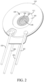
FIG. 2 is a schematic perspective view of the atomizer shown inFIG. 1 from another angle of view; -
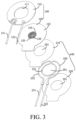
FIG. 3 is a schematic exploded view of the atomizer shown inFIG. 1 ; -
FIG. 4 is a schematic planar cross-sectional view of the atomizer shown inFIG. 1 ; -
FIG. 5 is a partial schematic view ofFIG. 4 ; -
FIG. 6 is an enlarged schematic view of portion A inFIG. 5 ; and -
FIG. 7 is a planar schematic cross-sectional view of an atomizer according to another embodiment. - For ease of understanding this application, this application is described more comprehensively below with reference to the related accompanying drawings.
- The accompanying drawings show exemplary implementations of this application. However, this application may be implemented in many different forms, and is not limited to the implementations described in this specification. On the contrary, the implementations are provided to make understanding of the disclosed content of this application more comprehensive.
- It needs to be noted that, when a component is referred to as "being fixed to" another component, the component may be directly on the other component, or an intermediate component may be present. When a component is considered to be "connected to" another component, the component may be directly connected to the other component, or an intermediate component may also be present. The terms "inner", "outer", "left", "right" and similar expressions used in this specification are only for purposes of illustration but not indicate a unique implementation.
- Referring to
FIG. 1 ,FIG. 2 , andFIG. 3 , anatomizer 10 provided by an embodiment of this application includes anultrasonic atomization assembly 100 and aheating assembly 200. Theultrasonic atomization assembly 100 is configured to atomize liquid to form liquid vapor, and the liquid may be oil, liquid medicine, or the like. When the liquid is atomized to form the liquid vapor, a user may inhale the liquid vapor. - Referring to
FIG. 3 ,FIG. 4, and FIG. 5 , in some embodiments, theultrasonic atomization assembly 100 includes a piezoelectricceramic piece 110, ametal piece 120, afirst electrode 131, and asecond electrode 132. An end of thefirst electrode 131 and an end of thesecond electrode 132 are electrically connected to a circuit in the piezoelectricceramic piece 110, and the other end of thefirst electrode 131 and the other end of thesecond electrode 132 are configured to be connected to an alternating current power supply. Therefore, the circuit in the piezoelectricceramic piece 110 is configured to be supplied with an alternating current. When the alternating current power supply supplies the alternating current to the circuit in the piezoelectricceramic piece 110 through thefirst electrode 131 and thesecond electrode 132, the piezoelectricceramic piece 110 generates high frequency vibration, so that a vibration frequency of the piezoelectricceramic piece 110 is equal to a vibration frequency of an ultrasound. A throughhole 111 is provided at a center of the piezoelectricceramic piece 110, and the throughhole 111 penetrates two opposite surfaces of the piezoelectricceramic piece 110. By providing the throughhole 111, the piezoelectricceramic piece 110 has a substantially circular structure. - The
metal piece 120 has a substantially disk-shaped structure and includes afirst support surface 121, asecond support surface 122, aliquid inlet surface 123, and avapor outlet surface 124. Theliquid inlet surface 123 and thevapor outlet surface 124 are opposite to each other and are located at a central region of themetal piece 120. Thesecond support surface 122 and thefirst support surface 121 are opposite to each other and are located at an edge region of themetal piece 120. Thesecond support surface 122 and thevapor outlet surface 124 are located on a second side (i.e. an upper side) of themetal piece 120, and thesecond support surface 122 is connected to a periphery of thevapor outlet surface 124, so that thesecond support surface 122 is circular and surrounds thevapor outlet surface 124. Thefirst support surface 121 and theliquid inlet surface 123 are located on a first side (i.e. a lower side) of themetal piece 120, and thefirst support surface 121 is connected to a periphery of theliquid inlet surface 123, so that thefirst support surface 121 is circular and surrounds theliquid inlet surface 123. In other words, both thesecond support surface 122 and thefirst support surface 121 are spaced apart along a thickness direction of themetal piece 120 and correspond to each other, and both theliquid inlet surface 123 and thevapor outlet surface 124 are spaced apart along the thickness direction of themetal piece 120 and correspond to each other. - A plurality of
atomization holes 126 are provided on themetal piece 120, and the atomization holes 126 penetrate both theliquid inlet surface 123 and thevapor outlet surface 124. Theheating assembly 200 is arranged on thefirst support surface 121 of themetal piece 120. The piezoelectricceramic piece 110 is attached to thesecond support surface 122 of themetal piece 120, so that thevapor outlet surface 124 corresponds to the throughhole 111 of the piezoelectricceramic piece 110, and the throughhole 111 is in communication with theatomization hole 126. Liquid to be atomized is located on a side at which theliquid inlet surface 123 is located, and the liquid is in direct contact with theliquid inlet surface 123, so that the liquid enters theatomization hole 126 through theliquid inlet surface 123. When the piezoelectricceramic piece 110 generates high frequency vibration under an action of an alternating current, vibration energy of the piezoelectricceramic piece 110 is transmitted to themetal piece 120, so that themetal piece 120 also generates high frequency vibration along with the piezoelectricceramic piece 110, so as to atomize the liquid in theatomization hole 126 to form liquid vapor. The liquid vapor is sprayed out from thevapor outlet surface 124 into the throughhole 111 of the piezoelectricceramic piece 110 to be inhaled by a user. In some embodiments, theatomization hole 126 is a conical hole, and a diameter of theatomization hole 126 is gradually reduced from theliquid inlet surface 123 to thevapor outlet surface 124. - The
metal piece 120 may be made of a stainless steel material, so that themetal piece 120 has good structural strength, thermal conductivity, and rust resistance. Therefore, it can be ensured that themetal piece 120 has sufficient anti-fatigue strength, which prevents fatigue fracture of themetal piece 120 under high frequency vibration, and improves a service life of the entireultrasonic atomization assembly 100. In addition, it can prevent a rust particle from partially or completely blocking theatomization hole 126, ensure that particle sizes of tiny liquid droplets in the liquid vapor are equal, and ensure that eachatomization hole 126 can atomize the liquid, so as to finally improve uniformity and reliability of themetal piece 120 in vaporizing the liquid. - In some embodiments, at least a part of both the
liquid inlet surface 123 and thevapor outlet surface 124 is aspherical crown surface 125. An opening of thespherical crown surface 125 faces theheating assembly 200, so that an entire central region of themetal piece 120 forms a spherical crown protrusion, and an opening of the protrusion is the opening of thespherical crown surface 125. The protrusion may also be formed by a central region of aflat metal piece 120 recessed toward the first side. Another part of theatomization hole 126 may be located on thespherical crown surface 125, and another part of theatomization hole 126 may be located at other parts of theliquid inlet surface 123 and thevapor outlet surface 124. Certainly, allatomization holes 126 may be located on thespherical crown surface 125. By providing thespherical crown surface 125, a plane perpendicular to a thickness direction of themetal piece 120 is used as a reference plane. Although an orthographic projection of ametal piece 120 having thespherical crown surface 125 on the reference plane is the same as that of theflat metal piece 120 on the reference plane, themetal piece 120 having thespherical crown surface 125 can ensure that the liquid vapor is sprayed in different directions and has a relatively large spraying range. In addition, a relatively large number ofatomization holes 126 may be provided, so that an atomization amount of liquid per unit time is increased to increase liquid vapor concentration. - Referring to
FIG. 3 ,FIG. 5, and FIG. 6 , in some embodiments, theheating assembly 200 includes a first insulatinglayer 210, a second insulatinglayer 220, and aheating layer 230. The first insulatinglayer 210, the second insulatinglayer 220, and theheating layer 230 are all substantially circular, and are provided with throughholes 201 in communication with each other. The throughholes 201 correspond to theliquid inlet surface 123 of themetal piece 120, and liquid may be in contact with theliquid inlet surface 123 through the throughholes 201 and enter theatomization hole 126 to be atomized. The first insulatinglayer 210 is attached to thefirst support surface 121 of themetal piece 120, and the first insulatinglayer 210 may be attached to thefirst support surface 121 through a physical vapor deposition (PVD) process or a screen printing process, so that the first insulatinglayer 210 is directly connected to themetal piece 120, so as to prevent the first insulatinglayer 210 from being connected to themetal piece 120 through another connection layer, and reduce a thickness and weight of theentire atomizer 10, which facilitates a thin and light design of theatomizer 10. The thickness of the first insulatinglayer 210 may range from 5 µm to 20 µm, for example, a specific value may be 5 µm, 10 µm, 15 µm, 20 µm, or the like. On the premise of ensuring that the first insulatinglayer 210 has sufficient insulating performance, the thickness of the first insulatinglayer 210 may be appropriately reduced, so that the thickness of theentire atomizer 10 may be further compressed. - The
heating layer 230 is attached to a surface of the first insulatinglayer 210 away from themetal piece 120, and theheating layer 230 may also be attached to the first insulatinglayer 210 through the physical vapor deposition (PVD) process or the screen printing process, so that theheating layer 230 is directly connected to the first insulatinglayer 210, to prevent theheating layer 230 from being connected to the first insulatinglayer 210 through another connecting layer, which may also reduce the thickness of theentire atomizer 10 and realize the thin and light design of theatomizer 10. The thickness of theheating layer 230 may range from 5 µm to 40 µm, for example, a specific value may be 5 µm, 20 µm, 30 µm, 40 µm, or the like. Theheating layer 230 may further include athird electrode 231 and afourth electrode 232. One end of thethird electrode 231 and one end of thefourth electrode 232 are electrically connected to theheating layer 230, and the other end of thethird electrode 231 and the other end of thefourth electrode 232 are configured to be connected to a direct current power supply. Therefore, theheating layer 230 is configured to be supplied with alternating current. Theheating layer 230 may convert electrical energy to heat energy when the direct current power supply (e.g. a battery) applies a direct current to theheating layer 230 through thethird electrode 231 and thefourth electrode 232. Theheating layer 230 may be a layered structure formed by bending a wire-like wire or directly be a layered structure formed by a conductive diaphragm. Theheating layer 230 may be a carbon nanoflake or may be made of a metal or alloy material such as a stainless steel material, a titanium metal material, or a titanium alloy material. - The second
insulating layer 220 is attached to a surface of theheating layer 230 away from themetal piece 120, and the second insulatinglayer 220 may also be attached to theheating layer 230 through the physical vapor deposition (PVD) process or the screen printing process, so that theheating layer 230 is directly connected to the second insulatinglayer 220, to prevent theheating layer 230 from being connected to the second insulatinglayer 220 through another connecting layer, which may also reduce the thickness of theentire atomizer 10 and realize the thin and light design of theatomizer 10. The thickness of the second insulatinglayer 220 may range from 5 µm to 20 µm, for example, a specific value may be 5 µm, 10 µm, 15 µm, 20 µm, or the like. On the basis of ensuring that the second insulatinglayer 220 has sufficient insulating performance, the thickness of the second insulatinglayer 220 may be appropriately reduced, so that the thickness of theentire atomizer 10 may be further compressed. The secondinsulating layer 220 may be made of a ceramic glaze material, so that the second insulatinglayer 220 has high wear resistance and good thermal conductivity. - Therefore, for the
entire heating assembly 200, the first insulatinglayer 210 is arranged on thefirst support surface 121 of themetal piece 120, and theheating layer 230 is directly sandwiched between the first insulatinglayer 210 and the second insulatinglayer 220. By providing the first insulatinglayer 210, a short circuit phenomenon caused by a direct contact between theheating layer 230 and themetal piece 120 may be avoided. By providing the second insulatinglayer 220, the second insulatinglayer 220 is in direct contact with liquid on a side of theliquid inlet surface 123, so as to avoid a short circuit phenomenon caused by a direct contact between theheating layer 230 and the liquid, and also avoid contamination on the liquid caused by a contact between theheating layer 230 and the liquid. - During operation of the
atomizer 10, theheating assembly 200 is activated before theultrasonic atomization assembly 100 is activated. Specifically, a direct current power supply is used for supplying power to theheating layer 230 through thethird electrode 231 and thefourth electrode 232, and then an alternating current power supply is used for supplying power to the circuit in the piezoelectricceramic piece 110 through thefirst electrode 131 and thesecond electrode 132, so that a working time of theheating layer 230 is earlier than a working time of the piezoelectricceramic piece 110. For example, theheating layer 230 may be activated no more than one second before the piezoelectricceramic piece 110 is activated, so that the piezoelectricceramic piece 110 can drive themetal piece 120 to vibrate to atomize liquid to form liquid vapor as soon as possible, which reduces time of waiting for the liquid vapor by a user, and improves user experience of theentire atomizer 10. - By activating the
heating assembly 200 first, theheating assembly 200 can preheat the liquid approaching theliquid inlet surface 123. Certainly, theheating assembly 200 may preheat the liquid to a temperature close to a body temperature. When themetal piece 120 atomizes the liquid to form liquid vapor sprayed from thevapor outlet surface 124 into the throughhole 111, the temperature of the liquid vapor is close to the body temperature. Especially for atomization of liquid medicine, when the user inhales the liquid medicine that has a temperature close to the body temperature and exists in a form of liquid vapor, the liquid medicine (liquid vapor) can be prevented from irritating a respiratory tract of a human body, so as to avoid other symptoms such as cough or elevated blood pressure, and ensure a therapeutic effect of the liquid medicine on the user. In addition, a temperature difference between the liquid vapor in an early stage and a middle-late stage of theheating assembly 200 due to simultaneous activating of theheating assembly 200 and the piezoelectricceramic piece 110 may be eliminated, the temperature of the liquid vapor in an atomization process may be kept consistent, and comfort of inhaling the liquid vapor may be improved. Further, for liquid with relatively high viscosity, through a preheating action of theheating assembly 200, the viscosity of the liquid can be appropriately reduced, thereby increasing fluidity of the liquid, making it easier for the liquid to enter theatomization hole 126 and to be rapidly atomized to form liquid vapor under high frequency vibration, thus avoiding a phenomenon that the liquid is difficult to flow into theatomization hole 126 or is difficult to be atomized to form the liquid vapor, and improving atomization efficiency, atomization stability, and atomization reliability of theentire atomizer 10. - If a
separate heating assembly 200 is used for heating the liquid, theheating assembly 200 simultaneously heat liquid near theliquid inlet surface 123 and liquid far away from theliquid inlet surface 123. When the liquid far away from theliquid inlet surface 123 reaches near theliquid inlet surface 123, theheating assembly 200 repeatedly heats the liquid, resulting in a waste of energy. In addition, due to a large amount of heated liquid, the liquid is heated up slowly, which also prolongs waiting time of the user. In the foregoing embodiment, theheating assembly 200 is directly attached to thefirst support surface 121 of theultrasonic atomization assembly 100, that is, theheating assembly 200 is integrated and arranged on theultrasonic atomization assembly 100. Therefore, theheating assembly 200 may merely heat liquid near theliquid inlet surface 123, i.e. a part of the liquid, so that heated liquid may directly enter theatomization hole 126 for atomization. In this way, the liquid is heated up quickly, energy consumption of theheating assembly 200 is reduced, and time for waiting the liquid vapor to spray is reduced to improve the user experience. - If the
heating assembly 200 is arranged on a side on which thevapor outlet surface 124 of themetal piece 120 is located, theheating assembly 200 cannot be in direct contact with liquid on a side of theliquid inlet surface 123, and heat generated by theheating assembly 200 is transferred to the liquid through themetal piece 120 to preheat the liquid, thus prolonging a heat transfer path, increasing a heat loss generated in a heat transfer process, and reducing a heat utilization rate of theheating assembly 200. In addition, theheating assembly 200 needs to be protected by a heat insulation part, to prevent heat of theheating assembly 200 from being transferred to another member of theatomizer 10 and causing damage to the member. Therefore, arrangement of the heat insulation part significantly complicates a structure of theatomizer 10. However, in the foregoing embodiment, theentire heating assembly 200 is directly arranged on thefirst support surface 121 of themetal piece 120, that is, theheating assembly 200 is located on a side on which theliquid inlet surface 123 is located, so that theheating assembly 200 can be in direct contact with the liquid, and heat generated by theheating assembly 200 is directly transmitted to the liquid without an intermediate medium, thereby reducing heat loss, improving a heat utilization rate, making the liquid heat up quickly, and reducing time for waiting the liquid vapor to spray. In addition, there is no need to set an additional heat insulation part on theheating assembly 200, thus simplifying an overall structure of theatomizer 10. - In some embodiments, the
heating layer 230 is configured to include a high temperature zone surrounding theliquid inlet surface 123 and a low temperature zone surrounding the high temperature zone, so that the high temperature zone of theheating layer 230 may be closer to theliquid inlet surface 123 than the low temperature zone. In some embodiments, theheating layer 123 includes afirst resistance wire 231 surrounding theliquid inlet surface 123 and asecond resistance wire 232 surrounding the first resistance wire. A resistance of thefirst resistance wire 231 is greater than a resistance of thesecond resistance wire 232. Because thefirst resistance wire 231 and thesecond resistance wire 232 are connected in series, heat generated by thefirst resistance wire 231 is more than heat generated by thesecond resistance wire 232 in the same time period, so that thefirst resistance wire 231 corresponds to the high temperature zone and thesecond resistance wire 232 corresponds to the low temperature zone. Therefore, heat generated by theheating layer 230 is more focused on the liquid near theliquid inlet surface 123, which may reduce repeated heating and increase a heating speed of the liquid. In addition, heat transferred by theheating layer 230 to another member of theatomizer 10 through an edge of themetal piece 120 may be reduced and an energy utilization rate of theheating layer 230 may be improved. In other embodiments, in a case that the resistance of thefirst resistance wire 231 is equal to the resistance of thesecond resistance wire 232, theliquid inlet surface 123 may be arranged closer to theheating layer 230 relative to an edge of thefirst support surface 121 of themetal piece 120. In other words, in a case that a distance h between theheating layer 230 and theliquid inlet surface 123 is less than a distance H between theheating layer 230 and the edge of thefirst support surface 121, the heat generated by theheating layer 230 may also be more focused on the liquid near theliquid inlet surface 123, thus improving the energy utilization rate of theheating layer 230. A thermal conductivity of the second insulatinglayer 220 is greater than a thermal conductivity of the first insulatinglayer 210, so that the heat generated by theheating layer 230 may be easily and directly transferred to the liquid through the second insulatinglayer 220, heat transferred to another member of theatomizer 10 through the first insulatinglayer 210 and themetal piece 120 may be reduced, and the energy utilization rate of theheating layer 230 may also be improved. - Referring to
FIG. 7 , in some embodiments, during a manufacturing process of theheating assembly 200, for example, aprepared heating layer 230 may be placed in an injection mold and then a liquid insulating material is injected to a cavity of the mold. The liquid insulating material may be cooled and solidified to form an insulating layer, and the insulating layer may be denoted as a thirdinsulating layer 241. Therefore, theentire heating layer 230 is packaged in the third insulatinglayer 241. By the action of the third insulatinglayer 241, short circuit caused by a contact between theheating layer 230 and themetal piece 120 as well as the liquid can be avoided. In some embodiments, the third insulatinglayer 241 may be provided with a slot structure, so that athird electrode 231 and afourth electrode 232 electrically connected to theheating layer 230 penetrate the slot structure. During a mounting process of theheating assembly 200, abonding layer 242 may be provided on thefirst support surface 121 of themetal piece 120, and the third insulatinglayer 241 is attached to thebonding layer 242. That is, the third insulatinglayer 241 is arranged on thefirst support surface 121 of themetal piece 120 through thebonding layer 242. Certainly, the third insulatinglayer 241 may be fixed on thefirst support surface 121 of themetal piece 120 through a snap connection. In another example, an insulating layer may be provided on both sides of theprepared heating layer 230 through physical vapor deposition, electrophoresis, or spraying, and then the insulating layer is fixed on themetal piece 120 through thebonding layer 242 or the snap connection. - This application further provides an electronic atomization device. The electronic atomization device includes the forgoing
atomizer 10. By arranging theatomizer 10, the user experience of the electronic atomization device can be improved, energy consumption can be reduced, and the structure can be thinner and lighter. - The technical features in the foregoing embodiments may be randomly combined. For concise description, not all possible combinations of the technical features in the embodiment are described. However, provided that combinations of the technical features do not conflict with each other, the combinations of the technical features are considered as falling within the scope recorded in this specification.
- The foregoing embodiments merely express several implementations of this application. The descriptions thereof are relatively specific and detailed, but should not be understood as limitations to the scope of this application. A person of ordinary skill in the art may further make several variations and improvements without departing from the ideas of this application, and such variations and improvements all fall within the protection scope of this application. Therefore, the protection scope of the patent of this application shall be subject to the appended claims.
Claims (15)
- An atomizer, comprising:an ultrasonic atomization assembly comprising a liquid inlet surface and a first support surface surrounding an edge of the liquid inlet surface, wherein the first support surface and the liquid inlet surface are located on the same side of the ultrasonic atomization assembly, and liquid enters the ultrasonic atomization assembly from the liquid inlet surface to be atomized to form liquid vapor; anda heating assembly attached to the first support surface and configured to preheat the liquid approaching the liquid inlet surface.
- The atomizer of claim 1, wherein the ultrasonic atomization assembly comprises a piezoelectric ceramic piece and a metal piece, the liquid inlet surface and the first support surface are both located on a first side of the metal piece, a second side of the metal piece opposite the first side has a second support surface corresponding to the first support surface and a vapor outlet surface corresponding to the liquid inlet surface, the piezoelectric ceramic piece is attached to the second support surface and is provided with a through hole corresponding to the vapor outlet surface, and the metal piece is provided with an atomization hole extending through the liquid inlet surface and the vapor outlet surface and in communication with the through hole.
- The atomizer of claim 2, wherein at least part of both the liquid inlet surface and the vapor outlet surface is a spherical crown surface, an opening of the spherical crown surface faces the first side, and the atomization hole is provided on the spherical crown surface.
- The atomizer of claim 2, wherein the heating assembly comprises a heating layer attached to the first side of the metal piece, and the heating layer is configured to comprise a high temperature zone surrounding the liquid inlet surface and a low temperature zone surrounding the high temperature zone.
- The atomizer of claim 4, wherein a distance between the edge of the liquid inlet surface and the heating layer is less than a distance between an edge of the first support surface and the heating layer.
- The atomizer of claim 4, wherein the heating layer comprises a first resistance wire surrounding the liquid inlet surface and a second resistance wire surrounding the first resistance wire, and a resistance of the first resistance wire is greater than a resistance of the second resistance wire.
- The atomizer of claim 4, wherein the heating assembly further comprises a first insulating layer and a second insulating layer, the first insulating layer is attached to the first support surface, and the heating layer is sandwiched between the first insulating layer and the second insulating layer.
- The atomizer of claim 7, wherein a thermal conductivity of the second insulating layer is greater than a thermal conductivity of the first insulating layer.
- The atomizer of claim 4, wherein the heating assembly further comprises a third insulating layer and a bonding layer, the heating layer is packaged in the third insulating layer, and the bonding layer is attached to the first support surface and is connected to the third insulating layer.
- The atomizer of claim 1, wherein the heating assembly is configured to be activated before the ultrasonic atomization assembly is activated.
- The atomizer of claim 2, wherein the atomization hole is a conical hole, and a hole diameter of the atomization hole is gradually reduced from the liquid inlet surface to the vapor outlet surface.
- The atomizer of claim 7, wherein the first insulating layer, the second insulating layer, and the heating layer are provided with through holes in communication with each other, the through holes correspond to the liquid inlet surface, and the liquid is in contact with the liquid inlet surface through the through holes and enters the atomization hole to be atomized.
- The atomizer of claim 7, wherein a thickness of the first insulating layer and/or the second insulating layer ranges from 5 µm to 20 µm.
- The atomizer of claim 4, wherein a thickness of the heating layer ranges from 5 µm to 40 µm.
- An electronic atomization device, comprising the atomizer of any one of claims 1 to 14.
Applications Claiming Priority (2)
| Application Number | Priority Date | Filing Date | Title |
|---|---|---|---|
| CN202011525441.5A CN112617297A (en) | 2020-12-22 | 2020-12-22 | Atomizer and electronic atomization device |
| PCT/CN2021/133814 WO2022135058A1 (en) | 2020-12-22 | 2021-11-29 | Atomizer and electronic atomization device |
Publications (1)
| Publication Number | Publication Date |
|---|---|
| EP4268637A1 true EP4268637A1 (en) | 2023-11-01 |
Family
ID=75320653
Family Applications (1)
| Application Number | Title | Priority Date | Filing Date |
|---|---|---|---|
| EP21909057.8A Pending EP4268637A1 (en) | 2020-12-22 | 2021-11-29 | Atomizer and electronic atomization device |
Country Status (4)
| Country | Link |
|---|---|
| US (1) | US20230329343A1 (en) |
| EP (1) | EP4268637A1 (en) |
| CN (1) | CN112617297A (en) |
| WO (1) | WO2022135058A1 (en) |
Families Citing this family (2)
| Publication number | Priority date | Publication date | Assignee | Title |
|---|---|---|---|---|
| CN112617297A (en) * | 2020-12-22 | 2021-04-09 | 深圳麦克韦尔科技有限公司 | Atomizer and electronic atomization device |
| WO2023215389A1 (en) * | 2022-05-03 | 2023-11-09 | Pneuma Respiratory, Inc. | Small active area plate ejector for droplet delivery device |
Family Cites Families (5)
| Publication number | Priority date | Publication date | Assignee | Title |
|---|---|---|---|---|
| CN104983078B (en) * | 2015-07-17 | 2018-11-30 | 湖南中烟工业有限责任公司 | A kind of electronic smoke atomizer and electronic cigarette |
| CN205922888U (en) * | 2016-06-20 | 2017-02-08 | 湖南中烟工业有限责任公司 | Ultrasonic nebulizer and ultrasonic atomization formula electron cigarette |
| CN108013512A (en) * | 2017-12-29 | 2018-05-11 | 深圳市华诚达精密工业有限公司 | A kind of flexible tobacco heating component and its production technology |
| CN109261428A (en) * | 2018-11-05 | 2019-01-25 | 东莞市谦合电子有限公司 | A kind of piezoelectric ceramic atomizer patch |
| CN112617297A (en) * | 2020-12-22 | 2021-04-09 | 深圳麦克韦尔科技有限公司 | Atomizer and electronic atomization device |
-
2020
- 2020-12-22 CN CN202011525441.5A patent/CN112617297A/en active Pending
-
2021
- 2021-11-29 EP EP21909057.8A patent/EP4268637A1/en active Pending
- 2021-11-29 WO PCT/CN2021/133814 patent/WO2022135058A1/en unknown
-
2023
- 2023-06-21 US US18/339,048 patent/US20230329343A1/en active Pending
Also Published As
| Publication number | Publication date |
|---|---|
| WO2022135058A1 (en) | 2022-06-30 |
| US20230329343A1 (en) | 2023-10-19 |
| CN112617297A (en) | 2021-04-09 |
Similar Documents
| Publication | Publication Date | Title |
|---|---|---|
| EP4268637A1 (en) | Atomizer and electronic atomization device | |
| US20100319685A1 (en) | Medical liquid droplet apparatus | |
| CN114365870B (en) | Atomizing assembly and electronic atomizing device | |
| CA2973880A1 (en) | Ultrasonic vaporizing element | |
| JPH02243165A (en) | Ultrasonic atomizer for liquid | |
| CN218185267U (en) | Heating element, atomizer and electronic atomization device | |
| CN215992754U (en) | Imbibition heating element, atomizer and aerosol generating device | |
| CN114847536A (en) | Atomizing core, atomizer and electronic atomization device | |
| EP1762264A1 (en) | Ultrasonic nebulizer | |
| JP2023098827A (en) | Ultrasonic atomization assembly and ultrasonic atomization device | |
| WO2023109341A1 (en) | Atomization member and electronic atomization device | |
| CN215013609U (en) | Atomizer and electronic atomization device | |
| CN107185766A (en) | A kind of piezoelectric ceramics ultrasound atomizer plate | |
| US20230191440A1 (en) | Microporous vaporization assembly and electronic vaporization device | |
| CN114794555A (en) | Ultrasonic atomization core and electronic atomizer | |
| CN217609576U (en) | Aerosol generator and atomising unit for liquid substrates | |
| WO2022021037A1 (en) | Heating piece, atomizer, and electronic atomizing apparatus | |
| CN115177025A (en) | Heating element, atomizer and electronic atomization device | |
| TW200940182A (en) | Nozzle plate of a spray apparatus and fabrication method thereof | |
| CN219785303U (en) | Atomizing subassembly and atomizing device | |
| CN220675139U (en) | Heating atomizing piece, atomizer and electronic atomizing device | |
| TWI290839B (en) | A high efficiency atomizer structure | |
| CN217826749U (en) | Ultrasonic atomization core and electronic atomizer | |
| CN219270169U (en) | Heating assembly and atomizer | |
| CN219644129U (en) | Heating film, aerosol generating assembly and aerosol generating device |
Legal Events
| Date | Code | Title | Description |
|---|---|---|---|
| STAA | Information on the status of an ep patent application or granted ep patent |
Free format text: STATUS: THE INTERNATIONAL PUBLICATION HAS BEEN MADE |
|
| PUAI | Public reference made under article 153(3) epc to a published international application that has entered the european phase |
Free format text: ORIGINAL CODE: 0009012 |
|
| STAA | Information on the status of an ep patent application or granted ep patent |
Free format text: STATUS: REQUEST FOR EXAMINATION WAS MADE |
|
| 17P | Request for examination filed |
Effective date: 20230616 |
|
| AK | Designated contracting states |
Kind code of ref document: A1 Designated state(s): AL AT BE BG CH CY CZ DE DK EE ES FI FR GB GR HR HU IE IS IT LI LT LU LV MC MK MT NL NO PL PT RO RS SE SI SK SM TR |
|
| DAV | Request for validation of the european patent (deleted) | ||
| DAX | Request for extension of the european patent (deleted) |