EP4268331B1 - Hochleistungs-pikosesekundenlasersystem mit gepulster optischer faser und abstimmbare dauer sowie verwendung eines solchen lasersystems - Google Patents
Hochleistungs-pikosesekundenlasersystem mit gepulster optischer faser und abstimmbare dauer sowie verwendung eines solchen lasersystems Download PDFInfo
- Publication number
- EP4268331B1 EP4268331B1 EP21843669.9A EP21843669A EP4268331B1 EP 4268331 B1 EP4268331 B1 EP 4268331B1 EP 21843669 A EP21843669 A EP 21843669A EP 4268331 B1 EP4268331 B1 EP 4268331B1
- Authority
- EP
- European Patent Office
- Prior art keywords
- pulse
- optical
- amplifier
- fibre
- energy
- Prior art date
- Legal status (The legal status is an assumption and is not a legal conclusion. Google has not performed a legal analysis and makes no representation as to the accuracy of the status listed.)
- Active
Links
Images




Classifications
-
- H—ELECTRICITY
- H01—ELECTRIC ELEMENTS
- H01S—DEVICES USING THE PROCESS OF LIGHT AMPLIFICATION BY STIMULATED EMISSION OF RADIATION [LASER] TO AMPLIFY OR GENERATE LIGHT; DEVICES USING STIMULATED EMISSION OF ELECTROMAGNETIC RADIATION IN WAVE RANGES OTHER THAN OPTICAL
- H01S3/00—Lasers, i.e. devices using stimulated emission of electromagnetic radiation in the infrared, visible or ultraviolet wave range
- H01S3/005—Optical devices external to the laser cavity, specially adapted for lasers, e.g. for homogenisation of the beam or for manipulating laser pulses, e.g. pulse shaping
- H01S3/0057—Temporal shaping, e.g. pulse compression, frequency chirping
-
- H—ELECTRICITY
- H01—ELECTRIC ELEMENTS
- H01S—DEVICES USING THE PROCESS OF LIGHT AMPLIFICATION BY STIMULATED EMISSION OF RADIATION [LASER] TO AMPLIFY OR GENERATE LIGHT; DEVICES USING STIMULATED EMISSION OF ELECTROMAGNETIC RADIATION IN WAVE RANGES OTHER THAN OPTICAL
- H01S3/00—Lasers, i.e. devices using stimulated emission of electromagnetic radiation in the infrared, visible or ultraviolet wave range
- H01S3/05—Construction or shape of optical resonators; Accommodation of active medium therein; Shape of active medium
- H01S3/06—Construction or shape of active medium
- H01S3/063—Waveguide lasers, i.e. whereby the dimensions of the waveguide are of the order of the light wavelength
- H01S3/067—Fibre lasers
- H01S3/06708—Constructional details of the fibre, e.g. compositions, cross-section, shape or tapering
-
- H—ELECTRICITY
- H01—ELECTRIC ELEMENTS
- H01S—DEVICES USING THE PROCESS OF LIGHT AMPLIFICATION BY STIMULATED EMISSION OF RADIATION [LASER] TO AMPLIFY OR GENERATE LIGHT; DEVICES USING STIMULATED EMISSION OF ELECTROMAGNETIC RADIATION IN WAVE RANGES OTHER THAN OPTICAL
- H01S3/00—Lasers, i.e. devices using stimulated emission of electromagnetic radiation in the infrared, visible or ultraviolet wave range
- H01S3/05—Construction or shape of optical resonators; Accommodation of active medium therein; Shape of active medium
- H01S3/06—Construction or shape of active medium
- H01S3/063—Waveguide lasers, i.e. whereby the dimensions of the waveguide are of the order of the light wavelength
- H01S3/067—Fibre lasers
- H01S3/06708—Constructional details of the fibre, e.g. compositions, cross-section, shape or tapering
- H01S3/06725—Fibre characterized by a specific dispersion, e.g. for pulse shaping in soliton lasers or for dispersion compensating [DCF]
-
- H—ELECTRICITY
- H01—ELECTRIC ELEMENTS
- H01S—DEVICES USING THE PROCESS OF LIGHT AMPLIFICATION BY STIMULATED EMISSION OF RADIATION [LASER] TO AMPLIFY OR GENERATE LIGHT; DEVICES USING STIMULATED EMISSION OF ELECTROMAGNETIC RADIATION IN WAVE RANGES OTHER THAN OPTICAL
- H01S3/00—Lasers, i.e. devices using stimulated emission of electromagnetic radiation in the infrared, visible or ultraviolet wave range
- H01S3/05—Construction or shape of optical resonators; Accommodation of active medium therein; Shape of active medium
- H01S3/06—Construction or shape of active medium
- H01S3/063—Waveguide lasers, i.e. whereby the dimensions of the waveguide are of the order of the light wavelength
- H01S3/067—Fibre lasers
- H01S3/06754—Fibre amplifiers
-
- H—ELECTRICITY
- H01—ELECTRIC ELEMENTS
- H01S—DEVICES USING THE PROCESS OF LIGHT AMPLIFICATION BY STIMULATED EMISSION OF RADIATION [LASER] TO AMPLIFY OR GENERATE LIGHT; DEVICES USING STIMULATED EMISSION OF ELECTROMAGNETIC RADIATION IN WAVE RANGES OTHER THAN OPTICAL
- H01S3/00—Lasers, i.e. devices using stimulated emission of electromagnetic radiation in the infrared, visible or ultraviolet wave range
- H01S3/10—Controlling the intensity, frequency, phase, polarisation or direction of the emitted radiation, e.g. switching, gating, modulating or demodulating
- H01S3/102—Controlling the intensity, frequency, phase, polarisation or direction of the emitted radiation, e.g. switching, gating, modulating or demodulating by controlling the active medium, e.g. by controlling the processes or apparatus for excitation
- H01S3/1022—Controlling the intensity, frequency, phase, polarisation or direction of the emitted radiation, e.g. switching, gating, modulating or demodulating by controlling the active medium, e.g. by controlling the processes or apparatus for excitation by controlling the optical pumping
- H01S3/1024—Controlling the intensity, frequency, phase, polarisation or direction of the emitted radiation, e.g. switching, gating, modulating or demodulating by controlling the active medium, e.g. by controlling the processes or apparatus for excitation by controlling the optical pumping for pulse generation
Definitions
- the present invention relates to the technical field of lasers for producing high peak power femtosecond (fs) or picosecond (ps) laser pulses.
- the present invention relates to the field of fiber optic lasers, which make it possible to deliver a laser pulse at the end of a waveguide that is completely flexible in all directions, without deteriorating the quality of the laser beam.
- Laser pulses with a duration of less than 10 ps are highly sought after for a wide variety of applications such as micromachining or eye surgery. It is known that the pulse duration is optimally less than 10 ps and a duration close to 1 ps is generally desirable. In order to be able to cause disruption of the material by laser induced breakdown, the peak power of the pulses generally needs to be greater than 1 MW.
- One of the difficulties encountered is being able to amplify ultrashort pulses ( ⁇ 10 ps) up to energies greater than 1 ⁇ J or even 10 ⁇ J.
- waveguides and in particular optical fibers It is thus possible to route the beam of a laser to any location in space and to modify its direction very easily.
- This type of waveguide is widely used in optical telecommunications and in power lasers used in industrial applications. There are thus lasers with continuous radiation or producing long pulses, i.e. with a duration greater than 1 ns, using optical fibers in order to move the laser beam over a distance of several meters or even tens of meters.
- These systems can be integrated into robot arms or in handpieces. The end through which the beam is emitted can thus move along 6 axes.
- the pulse duration becomes less than 1 ns or if the peak power typically exceeds 300 kW
- the propagation over a few meters in a single-mode fiber gives rise to the appearance of non-linear effects such as the Raman effect and/or self-phase modulation that degrade the spatial and/or temporal properties of the laser pulse.
- ultra-short pulses i.e. those with a duration of typically less than 10 ps
- the method of frequency drift pulse amplification is also known, which consists of transforming initially very short pulses (generally with a duration of less than 1 ps) by stretching them by a factor E up to several tens or even hundreds of picoseconds. Their peak power is then reduced by the same factor E, allowing their amplification without suffering the deleterious non-linear effects.
- a dispersive system called a compressor, generally composed of two diffraction gratings.
- Frequency drift pulse amplification systems require the use of an ultra-short pulse source, a pulse stretcher and a compressor that is very bulky and very sensitive to vibrations and movements. Their integration into an industrial system is complicated and requires the use of a set of mirrors to guide the beam to the part to be treated. In addition, the stretching and compression factors must be finely adjusted, which requires an adjustable stretcher and/or compressor.
- the amplifiers are composed of optical fibers doped with ions allowing the amplification of a light wave.
- the fibers used In order to maintain the quality of the laser beam, the fibers used, whether passive or active, must be perfectly single-mode. It is also known that despite the efforts of optical fiber manufacturers, current optical fibers with a core diameter greater than typically 15 ⁇ m are only single-mode if they are kept perfectly fixed. These fibers can be flexible and can be coiled according to various geometric figures but once the position has been chosen in order to produce a good quality beam, any movement of the fiber causes a modification of the geometric properties of the beam (shape, direction, power, etc.). These instabilities are particularly sensitive for short fibers, since higher order propagation modes cannot be filtered during propagation in the fiber over a long length.
- hollow core fibers to transport ultra-short laser pulses.
- These hollow core fibers effectively avoid all the difficulties related to non-linear effects during propagation in a solid medium but cannot be amplified and cannot be welded onto conventional glass fibers.
- Frequency drift amplification has also been used to avoid nonlinear effects in active or passive fibers, whether they are step-index or photonic structure by temporally stretching the pulses before their propagation.
- a very high stretching factor > 500
- Such a compressor is heavy and sensitive to vibrations or shocks. This method is therefore not compatible with a flexible 3D displacement of the beam.
- EP 1 712 936 proposes to use multimode fibers whose core diameter is significantly larger than that of a single-mode fiber.
- the desired fundamental mode is converted into a higher-order mode before injecting it into the fiber.
- This system requires the use of a stretcher before injecting the pulse into the fiber and a mode converter to bring the multimode beam back to a usable shape close to that of a single-mode beam. Furthermore, it is sensitive to coupling between modes and therefore to fiber movements.
- the aim of the present invention is to propose a method for producing pulses of duration less than 10 picoseconds and preferably less than 3 picoseconds, of tunable duration and high energy, i.e. greater than 100 nJ, easily orientable and movable in all directions without altering the spatial quality of the beam.
- the present disclosure provides a fiber optic laser system according to claim 1.
- the laser system is fully fibered between the injector and the compressor.
- all the fibers used are single-mode optical fibers with a core diameter of less than 25 micrometers, and preferably less than 15 microns, or even less than 10 microns.
- the fibers are step-index or photonic crystal structure optical fibers comprising a solid core surrounded by a sheath of hollow capillaries.
- the single-mode optical fibers can be oriented and bent with a minimum bending radius of less than 50 cm and greater than 5 cm, while preserving the quality of the laser beam and the single-mode appearance.
- the last optical fiber amplifier is flexible along at least two rotation axes transverse to the longitudinal optical axis at the end of the last optical fiber amplifier. More specifically, the assembly formed by the compressor and the end of the last active optical fiber amplifier is flexible around at least two axes of rotation transverse to the longitudinal optical axis at the end of the last optical amplifier, with a minimum radius of curvature less than 50 cm.
- This fiber optic laser system structure makes it possible to generate a compressed laser pulse of duration less than 10 picoseconds or even 3 picoseconds, of high energy and of tunable duration.
- the end of the last fiber optic amplifier fixed to the compressor is easily orientable and movable in all directions without altering the spatial quality of the pulsed laser beam.
- the compressor is non-adjustable (it is preset during manufacture), which makes it possible to maintain a reduced volume, while using a volume compressor capable of withstanding a high energy pulse.
- the source pulse has an energy greater than 1 nanojoule.
- the invention also provides the use of a fiber optic laser system according to one of the embodiments in a micromachining device, a medical device, an ophthalmic surgery device or a skin tattoo removal device.
- FIG. 1 schematically represents a fiber optic laser system in accordance with the present disclosure for generating a compressed pulse 17 of picosecond or femtosecond duration, of high energy and adjustable in duration.
- the laser system comprises an injector 100, a spectro-temporal shaping module 110, an optical amplification system associated with a spectral filtering device, a compressor 170 and energy adjustment means 180.
- the injector 100 produces one or more source pulses 10.
- the spectro-temporal shaping module 110 receives a source pulse 10 and generates a spectrally broadened pulse 11.
- the optical amplification system combined with the spectral filtering device receives a spectrally broadened pulse 11 and forms an amplified pulse 14.
- the compressor 170 receives the amplified pulse 14 and generates a compressed pulse 17.
- the injector 100 produces source pulses 10 of a duration between 30 and 100 ps.
- the injector 100 comprises for example a laser oscillator.
- the energy adjustment means 180 make it possible to adjust the energy of the source pulse 10 emitted by the injector 100. Since the energy of the pulse injected into the optical amplifier system is adjustable, the energy of the amplified pulse is indirectly adjustable. Consequently, the injector 100 combined with the energy adjustment means 180 makes it possible to generate a source pulse 10 of adjustable energy.
- the energy of the source pulse at the output of the injector is generally in a range between 0.1 nJ and 2 nJ.
- the duration of the source pulse is for example determined by the spectral width of the filter contained in the cavity of the laser oscillator. For a given injector, the duration of the source pulses 10 is therefore generally constant as a function of time, from one pulse to the next.
- the duration of the source pulse is here between 30 ps and 100 ps.
- the energy adjustment of a source pulse 10 generally does not affect its duration.
- the source pulse 10 is emitted in a spectral band B 0 around an emission wavelength, for example 1030 nm, the spectral band B 0 having a width between 0.03 nm and 0.3 nm.
- the spectro-temporal shaping module 110 is arranged between the injector 100 and the optical amplification system.
- the spectro-temporal shaping module 110 consists of a passive single-mode fiber with a length of between 100 m and 1000 m. This fiber is polarization-preserving and has a core with a diameter of between 5 and 12 ⁇ m. Examples of fibers useful for this application are the PM980 (Nufern, USA or YOFC, China) or the HI1060 (Corning, USA).
- the spectro-temporal shaping module 110 receives a source pulse 10.
- the propagation of the source pulse in the passive optical fiber induces a self-modulation effect of the phase of the pulse which depends on the light intensity of the source pulse and which produces a spectral broadening proportional to the peak power of the injected pulses and to the length of the fiber.
- the pulse undergoes the combined effects of group velocity dispersion (variation of the index with the wavelength) and self-phase modulation (variation of the index with the instantaneous power).
- the spectral and temporal phase of the pulse is then modified and takes a shape which depends on the parameters of the fiber and the pulse used. In particular the frequency drift (derivative function of the phase with respect to the frequency) depends on these parameters.
- the spectro-temporal shaping module 110 fulfills a phase adapter function upstream of the optical amplifier system.
- the energy adjustment means 180 make it possible to adjust the energy of the source pulse emitted by the injector 100 and thus to vary the frequency drift of the pulse from the spectro-temporal shaping module 110.
- the spectro-temporal shaping module 110 makes it possible to generate a spectrally broadened pulse 11, having a frequency drift controlled as a function of the energy of the source pulse.
- the spectral bandwidth of the spectrally broadened pulse 11 is adjustable as a function of the energy of the source pulse.
- the spectrally broadened pulse 11 has a spectral bandwidth that extends around the source wavelength and that is 5 to 50 times wider than the spectral width B0 of the source pulse.
- the spectral bandwidth of the spectrally broadened pulse 11 is greater than 0.3 nm. This spectrally broadened pulse 11 is injected into the optical amplification system and into the associated spectral filtering device.
- the optical amplification system consists of single-mode optical fiber(s).
- the optical amplification system comprises at least one last optical amplifier 150.
- the optical amplification system comprises at least one first optical amplifier 130 and the last optical amplifier 150 arranged in series.
- the optical amplification system comprises more than two optical fiber amplifiers arranged in series to form successive amplification stages.
- a passive optical fiber section with a fiber length of less than 10m, can be inserted between two amplification stages.
- a single-mode passive optical fiber can be inserted upstream of the last optical fiber amplifier 150 to allow the flexible optical fiber length to be extended.
- an active optical fiber is a double-clad optical fiber having a core doped with rare earth ions, for example ytterbium ions.
- the double-clad structure allows optical pumping by injecting the radiation of one or more laser diodes into the first cladding, called the pump cladding.
- the active optical fibers are preferably polarization-maintaining. These fibers are well known to those skilled in the art and are not described here. They may be step-index or have a photonic crystal structure.
- the guiding of the pump radiation may be obtained by step-index between the core and a solid cladding surrounding the core or by a ring of very thin capillaries (air clad) surrounding the core.
- the absorption of the pump radiation injected into the pump cladding is typically between 3 dB/m and 20 dB/m at the pump wavelength.
- the energy adjustment means 180 also make it possible to directly adjust the energy of the amplified pulse at the optical amplifier system, for example by adjusting the current of a pump diode for at least one optical fiber amplifier of the amplification system.
- the amplifier being composed of at least one optical fiber, the adjustment of the energy of the amplified pulse induces a variation of the phase modulation at the crossing of this amplifier and of all the fibers located downstream of this amplifier and consequently a modification of the duration of the compressed pulse.
- a spectral filter 120, respectively 140 is arranged upstream of each optical amplifier 130, respectively 150. More precisely, the last spectral filter 140 is arranged upstream of the last optical amplifier 150.
- a first spectral filter 120 is arranged upstream of the first optical amplifier 130, also called an optical pre-amplifier.
- each optical amplifier is associated with a spectral filter arranged upstream.
- the spectral filter is adjacent to the optical amplifier with which it is associated.
- a spectral filter is composed for example of a glass plate supporting a multi-dielectric treatment whose transmission is maximum around the wavelength of the source pulse and very low outside this zone.
- This filter is advantageously placed in a component comprising an input for a fiber followed by a free-space collimation lens, itself followed by the free-space filter followed by a second refocusing lens in an output fiber.
- a fibered Bragg grating or possibly a massive Bragg grating placed in a free-space component can be used.
- the last spectral filter 140 is generally a bandpass filter. More precisely, the spectral filter 120, respectively 140, is chosen to transmit a spectral band of approximately 50 nm and less than 100 nm, centered on the wavelength of the source pulse, for example 1030 nm, while strongly attenuating the generation of a parasitic Raman signal in each optical amplifier 130, respectively 150. This spectral band can be voluntarily reduced to 8 nm or even 4 nm around the central wavelength of the source pulse.
- the spectral filter 120 receives a spectrally broadened pulse 11 with adjustable frequency drift depending on the energy of the source pulse and transmits a spectrally filtered pulse 12 to the first optical amplifier 130.
- the first optical amplifier 130 amplifies the filtered pulse 12 and generates a pre-amplified pulse 13.
- the spectral filter 140 receives the pre-amplified pulse 13 and transmits a spectrally filtered pulse 14 to the last optical amplifier 150.
- the last optical amplifier 150 amplifies the filtered pulse 14 and generates an amplified pulse 15.
- the spectral filter 120, respectively 140 thus makes it possible to limit a power transfer to a Raman line likely to appear in the optical fiber of the spectro-temporal shaping module or in the optical fiber amplifiers 130, 150, by stimulated Raman effect, this Raman line being likely to grow as it propagates and amplifies.
- the Raman radiation is strongly attenuated or even eliminated after each stage in order to avoid the progressive growth of the Raman radiation, while accumulating during the different propagation or amplification stages a spectral broadening by self-phase modulation.
- the spectral filter 120 makes it possible to accumulate the self-phase modulation by eliminating the power of the Raman line at each pass of a filter.
- Nonlinear optical effects including self-phase modulation and the Raman effect are proportional to the product of the length traversed by the local light intensity. These nonlinear optical effects are therefore particularly important in the final part of the amplifier system in which the energy of the pulses is maximum.
- the power produced by the amplifier(s) is likely to be limited by the appearance of Raman radiation.
- the length of the active fiber of the last amplifier 150 is limited, and on the other hand, any passive optical fiber after the last amplifier 150 is eliminated. This arrangement makes it possible to limit the length of fiber traversed by the amplified pulse. Flexible offset cannot be achieved by using an amplifier housed in the main laser housing followed by a passive fiber section which would ensure flexible transport of the pulses.
- the last fiber section comprises a passive optical fiber section followed by the last optical amplifier 150 consisting of an active fiber section.
- the passive fiber and the active fiber have core diameters that are close or even identical, for example two fibers with a core diameter of 10 ⁇ m or a passive fiber of 10 ⁇ m and an active fiber of 12 ⁇ m or a passive fiber of 10 ⁇ m and an active fiber of 14 ⁇ m and are both double-clad structures.
- the active fiber of the last optical amplifier 150 has a core diameter of between 9 ⁇ m and 20 ⁇ m, and advantageously between 10 ⁇ m and 15 ⁇ m.
- the active fiber of the last optical amplifier 150 has a length of less than 2 m and preferably less than 1 m. In one embodiment, for example for a last optical amplifier 150 having a length of 1 m, the passive fiber has a length of approximately 3 m.
- the active fiber of the last optical amplifier 150 has a core doped with ytterbium ions.
- the passive fiber of the last section upstream of the last optical amplifier 150 makes it possible to increase the laser-matter interaction volume in which the distal end of the last optical amplifier 150 can be moved, without modifying the properties of the amplified laser pulse.
- the amplified pulse 15 has an energy greater than or equal to approximately 1 microjoule ( ⁇ J). In addition, this energy is adjustable according to the energy of the source pulse. In a complementary manner, the energy of the amplified pulse 15 is further adjustable, for example when the energy adjustment means 180 make it possible to adjust the pump current of at least one optical amplifier.
- the compressor 170 is arranged downstream of the optical amplification system. More specifically, the compressor is attached to the distal end of the last optical fiber amplifier 150.
- the active fiber of the last amplifier can be equipped with a FC-APC or equivalent connector that is connected to the mechanical part supporting the compressor, or be fixed in a collimator that makes it possible to produce a collimated beam, said collimator being attached to the compressor support.
- the compressor 170 is massive and non-adjustable. In other words, the spectral phase shift introduced by the compressor is fixed.
- the compressor 170 having a predetermined dispersion of approximately 5 to 30 ps/nm, it does not include any adjustment means and has a reduced size.
- the compressor has typical dimensions of 5 mm x 5 mm x 7 mm and is included in a mechanical module which has for example a volume of 2 cmx2cmx2cm on sides.
- the compressor 170 allows compression of a factor typically 20 to 50 for an initial pulse of 50 ps. Since the compressor is not adjustable, it is stable with respect to external disturbances, for example vibrations.
- the compressor 170 is composed of a fixed set of two diffraction gratings in series on the optical path according to the conventional compression scheme.
- the compressor 170 is composed of a massive Bragg grating with variable pitch (or CVBG according to the English terminology for Chirped Volume Bragg Grating, produced for example by the company OPTIGRATE, Florida, USA). More precisely, a Bragg grating with variable pitch has a drift of the diffraction pitch along its propagation axis.
- a Bragg grating with variable pitch is known to be able to produce a spectral phase shift very close to a parabola and therefore a quasi-linear frequency drift.
- the compressor 170 receives the amplified pulse 15 at the output of the last amplifier 150 and forms a compressed pulse 17 of high energy.
- the energy, respectively the peak power of the compressed pulse 17 is of the order of 1 ⁇ J to 30 ⁇ J, respectively 500 kW to 30 MW.
- the duration of the compressed pulse 17 is less than 10 ps, or even less than 3 ps, or even less than 1 ps, that is to say in the femtosecond domain. More precisely, the duration of the compressed pulse 17 is adjustable according to the energy of the source pulse.
- the adjustment of the duration of the compressed pulse 17 is of crucial importance in certain applications, for example in eye surgery, particularly in cataract surgery.
- an increase of the order of 20% to 25% of the energy of the source pulse makes it possible to vary the duration of the compressed pulse from 2 ps to 1 ps (see Figure 6 ), without any other adjustment of the laser system (no adjustment in phase or dispersion of the compressor in particular).
- a reduction in the pulse duration by a factor of 2 corresponds to an increase in peak power by a factor of 2.
- Controlling the energy of the source pulse and therefore of the amplified pulse makes it possible to very finely control the peak power delivered at the output of the compressor. This control is here carried out entirely and solely via an electronic control system and does not require any optical or optomechanical adjustment. Consequently, according to the present disclosure, the adjustment of the pulse duration can be carried out more quickly than with a mechanical or optomechanical system. This makes it possible to adjust the duration of each pulse individually and therefore to optimise the laser-matter interaction for example.
- FIG. 2A represents a first exemplary embodiment of an injector in a laser system according to the present disclosure.
- the injector 100 here comprises a laser oscillator 200, an optical source preamplifier 220 and a pulse selector 230.
- the laser oscillator 200 generates at least one initial pulse 1 of duration d 0 and spectral band B 0 .
- the optical source preamplifier 220 makes it possible to increase the intensity/energy of the pulse initial 1 and to generate a preamplified initial pulse 2, without modifying its duration or its spectral band. More precisely, the energy adjustment means 180 make it possible to adjust the intensity/energy of the preamplified initial pulse 2.
- the pulse selector 230 makes it possible to modify the rate of the laser source and to select one or more source pulses 10 also called input pulse from among the preamplified initial pulses 2.
- the laser oscillator 200 generates initial pulses 1 at a rate generally between 1 MHz and 100 MHz.
- the pulse selector 230 makes it possible to reduce the rate of the source pulses 10 or to select a source pulse 10 on demand.
- the pulse selector is for example an acousto-optic modulator or an electro-optic modulator. In addition to its role of adjusting the source rate, it can possibly modulate the energy of the pulses 10.
- the injector 100 comprises an optical source preamplifier 220 and a pulse selector 230
- the optical source preamplifier 220 can be arranged either upstream or downstream of the pulse selector 230.
- this source pulse 1 is injected into the optical source preamplifier 220 in order to bring the energy of the preamplified initial pulse 2 to a value greater than 100 pJ and preferably to a value greater than 1000 pJ or 1 nJ.
- the gain of the optical source preamplifier 220 is electronically adjustable using the energy adjustment means 180, which makes it possible to adjust the energy of the source pulse 10 at the output of the injector 100.
- the optical source preamplifier 220 takes the form of a doped fiber pumped by one or more laser diodes.
- doping materials for active optical fibers include ytterbium (Yb), neodymium (Nd), erbium (Er), erbium-ytterbium (Er/Yb) co-doping, holmium (Ho), thulium (Tm), Yb,Tm co-doping, but are not limited to this list.
- the source optical preamplifier 220 is pumped by one or more laser diodes. Adjustment of the gain of the source optical preamplifier can thus be done by adjusting the parameters of the pump diode(s), such as for example their supply current.
- the rate of the oscillator 200 is typically 10 to 100 MHz but may be less than 10 MHz or even less than 1 MHz without being less than the final rate of production of the compressed pulses 17. If the rate of the oscillator 200 does not correspond to that desired for the compressed pulses 17 at the output of the system, the initial pulse 1 or, respectively, the preamplified initial pulse 2 is injected into a selector pulse selector 230 which reduces the rate and selects the source pulses 10 intended to be amplified.
- This pulse selector 230 is for example an acousto-optic modulator whose inputs and outputs are fibered. It can also take the form of an electro-optic modulator or any other element fast enough to select the pulses.
- the pulse selector 230 is optional if the oscillator 200 operates directly at the desired rate at the output of the system. This is usually the case for a triggered or modulated laser diode oscillator.
- the injector comprises a laser oscillator 200, an optical source preamplifier 220, a pulse selector 230 and an optical attenuator 260.
- the energy of the source pulses 10 is finely adjusted by means of a component which can take the form of an attenuator or a controllable modulator.
- the optical attenuator 260 can be a separate element or be included in the same optical modulator 270 as the pulse selector 230.
- An acousto-optic modulator makes it possible, for example, to select the pulses one by one and at the same time to adjust the energy of these pulses at the output of the modulator.
- a train of initial pulses of energy of the order of 1 nJ at a rate of 20 MHz can be transformed into a train of source pulses 10 at a rate of for example 250 kHz and of energy adjustable between 0.01 nJ and 0.5 nJ.
- the rate of the source pulses 10 can also be chosen independently among the sub-multiples of 20 MHz.
- the advantage of a fast modulator such as an acousto-optic or electro-optic modulator is that it allows to modulate the energy of the source pulses 10 one by one and to produce pulse trains of adjustable energy for each source pulse 10.
- the injector 100 is controlled by a control unit 180 which makes it possible to modulate the energy of each source pulse 10 independently.
- the energy of the source 10 is modulated, which will have the effect of slightly modifying the energy of the amplified 15 and compressed 17 pulses, but above all of modifying their compressed duration.
- the injector 100 is then capable of producing a train of source pulses 10 at a maximum rate which is the rate, denoted F0, of the laser oscillator 200 but which can be any rate that is a submultiple (F0/n) of this initial rate, n being an integer, each source pulse 10 having an adjustable energy.
- the injector 100 can also produce packets of N source pulses 10 at the rate F0 or at a lower rate F0/n, these packets being generated periodically or non-periodically. Generally, the injector 100 produces a train of source pulses 10 at the rate desired by the user and whose energy is adjustable.
- FIG 3 schematically represents a fiber optic laser system according to a first exemplary embodiment.
- This fiber optic laser system comprises an injector 100 as described in connection with the figure 2A or 2B , a 110 fiber optic spectro-temporal shaping module, a series of 130, 150 doped fiber optical amplifiers and a compressor 170.
- This fiber optic laser system allows the production of ultra-short pulses of high energy.
- the series of optical amplifiers 130, 150 with doped fiber allows the energy of the pulses to be increased by a factor of 1000, or even 10,000 or 100,000 or 1,000,000 or more. Examples of doping materials for optical fibers include Yb, Nd, Er, Er/Yb, Ho, Tm, Yb/Tm ions, but are not limited to this list.
- the compressor 170 allows the duration of the amplified pulses to be compressed by a factor greater than 10.
- the present disclosure uses self-phase modulation and a spectro-temporal shaping module 110.
- the self-phase modulation phenomenon creates a spectral broadening accompanied by a modulation of the phase.
- the frequency drift associated with the phase modulation created in all the elements located between the injector 100 and the compressor 170, including the optical amplifiers 130, 150 correspond precisely to the frequency drift induced in the compressor 170 to the nearest sign.
- the positive drift due to the self-phase modulation is compensated by a negative drift induced by the compressor.
- the present disclosure uses a spectro-temporal shaping module 110 that allows adjusting the frequency drift of the amplified pulse 15 at the input of the compressor 170.
- the spectro-temporal shaping module 110 is composed of a passive polarization-preserving single-mode optical fiber whose length in meters is between 6 and 12 times the duration in picoseconds of the source pulse 10 incident on this fiber.
- the energy of the source pulse 10 injected into the fiber 110 is adjusted by means of the energy adjustment means 180.
- the diameter of the core of this fiber 110 is between 5 and 10 ⁇ m and generally between 5 and 7 ⁇ m.
- the spectrum of the spectrally broadened pulse 12 at the output of this fiber 110 is broadened by a factor of between 5 and 30.
- a spectral broadening factor greater than 30 is harmful because it is likely to induce the appearance of stimulated Raman scattering which will distort the pulse.
- the profile of the spectrally broadened pulse 12 is only slightly modified in this propagation. Its duration remains less than 1.5 times the duration of the source pulse 10 and the parabolic quality factor introduced by Pierrot is greater than 0.13.
- the spectrally broadened pulse 12 is therefore not considered quasi-parabolic. Nevertheless, it can be shown using a fiber propagation simulation code that when this spectro-temporal shaping module 110 is followed by a non-linear optical amplifier in which the spectrum of the pulse will again be broadened by a factor of 3 to 20, the final frequency drift after amplification is linear over a significant portion of the amplified pulse 15, which significantly improves the quality of the compressed pulses 17.
- the spectrally broadened pulse beam 12 from the spectro-temporal shaping module 110 is coupled into one or more components that provide isolation between the amplification stages and spectral filtering of wavelengths outside a spectral band close to that of the source 100.
- the filters 120, 140 have a very low transmission at the wavelength of the Raman frequency produced by the radiation from the source 100. This value is easily calculable from known parameters such as the Raman shift of fused silica (450 cm -1 ).
- the filter 120, 140 is chosen to have a high transmission around 1030 nm, for example between 1025 nm and 1035 nm, and very low transmission around 1080 nm.
- An example of a filter is a transmission filter having a transmission greater than 90% over the 1026 - 1034 nm band and a transmission less than 1% over the 1050 nm - 1150 nm band.
- the spectrally broadened pulse 12 propagates in a passive fiber 330 which guides the pulse to the input of the first active fiber amplifier 130.
- the spectral filter 120 and the optical isolator are included in the same fiber component which provides both the filtering and isolation functions.
- the passive fiber 330 and the active fiber 130 have an identical or very close diameter and typically between 5 and 11 ⁇ m.
- the active fiber of the first amplifier 130 has a length between 1 m and 5 m and preferably between 1 m and 2 m.
- the active fiber of the first amplifier 130 is pumped by one or more laser diodes 322.
- the pump radiation is injected into the pump sheath of the active fiber of the first amplifier 130 for example using a pump combiner 321.
- the gain of the first amplifier 130 is typically from 10 to 1000, and advantageously between 10 and 100.
- a second assembly comprising an optical isolator and a last spectral filter 140 is arranged at the output of the first amplifier 130.
- the last spectral filter 140 operates on the same principle as the first spectral filter 120.
- the spectrally broadened pulse 14 from this optical isolator and last spectral filter 140 assembly is transmitted to a passive optical fiber 360 through another pump combiner 351.
- the pump combiner 351 makes it possible to inject into the passive fiber 360 the pump radiation of one or more pump diodes 352.
- the passive fiber 360 is for example a polarization-preserving double-clad passive fiber whose core and cladding diameters are substantially identical to those of the active fiber of the last amplifier 150 to which it is welded.
- the length of the passive fiber 360 is between 1 and 10 m and preferably between 1 and 3 m in order to limit non-linear effects in this fiber.
- the passive fiber 360 has a core having a core diameter of approximately 10 to 20 ⁇ m.
- the active fiber of the last amplifier 150 is a double-clad fiber whose core is doped with rare earth ions.
- the active fiber of the last amplifier 150 is a ytterbium-doped fiber with a core diameter of 12.5 ⁇ m.
- the absorption of the fiber for a pump injected into the cladding with a diameter typically of 105 ⁇ m is of the order of 8 dB/m at 976 nm.
- the gain of this active fiber 150 is between 100 and 3000 and preferably between 300 and 1000.
- the energy of an amplified pulse 15 from the last amplifier 150 exceeds 1 ⁇ J and preferably lies between 10 ⁇ J and 40 ⁇ J.
- the energy per pulse is limited by the appearance of Raman radiation linked to the very strong non-linear optical effects in the last amplifier 150. In order to limit these effects, it is appropriate to limit the length of the active fiber of the last optical amplifier 150 as much as possible. A length of 0.7 m is a good example of optimization.
- the assembly consisting of the passive fiber 360 and the active fiber 150 is advantageously protected by a flexible metal or plastic sheath which covers in particular the weld between the fibers 360 and 150. This sheath is flexible and makes it possible to position the end of the active fiber of the last amplifier 150 in all directions and all positions over a volume of at least 2 m in diameter.
- the radiation of the amplified pulse 15 from the last active fiber amplifier 150 is incident on the compressor 170 whose frequency drift is fixed and not adjustable.
- An example of a compressor of this type is sold by OPTIGRATE (Oviedo, USA) under the reference CBG-1030-XX.
- the dispersion of this compressor is typically between 7 and 50 ps/nm and preferably less than 30 ps/nm.
- the compressor 170 is adapted to support the transmission of compressed pulses 17 of duration less than 3 ps with energies greater than 1 ⁇ J. These operating parameters are incompatible with a fibered dispersive Bragg grating compressor.
- the compressor 170 is fixedly attached to the active fiber of the last amplifier 150.
- the compressor 170 has dimensions compatible with the easy movement of the end of the fiber to which it is attached in all directions and positions. For example, its size is less than 50x50x50 mm and in our example less than 25 x 25 x 25 mm.
- the beam diameter in the compressor 170 is chosen to allow propagation without damage in the components of the system of the intended application which will host the laser source, for example 3 mm. A smaller or larger diameter is of course possible without altering the performance of the present invention.
- FIG 4 illustrates an interesting variation of the fiber optic laser system of the figure 3 .
- the spectro-temporal shaping module 110 is used in reflection.
- the output of the injector 100 is coupled into an optical circulator 411 well known to those skilled in the art.
- the optical circulator 411 directs the source pulse 10 towards a passive optical fiber 410 of half the length of the passive fiber of the spectro-temporal shaping module 110 described in connection with the figure 3 .
- the passive optical fiber 410 is a single-mode fiber with polarization preservation, whose length in meters is between 3 and 5 times the duration of the incident pulse on this fiber in picoseconds.
- a 412 fiber Bragg mirror with a spectral width between 0.1 and 3 nm centered at the wavelength of the source pulse is welded to the end of this passive optical fiber 410.
- the 412 fiber Bragg mirror returns the laser pulse for a second pass in the passive optical fiber 410 and also eliminates any radiation outside a spectral band a few nanometers wide, centered on the laser wavelength.
- the 412 fiber Bragg mirror eliminates in particular the Raman radiation resulting from the propagation in the fiber 410 before reflection on this Bragg mirror. On the other hand, it reflects the pulse broadened spectrally by the self-phase modulation undergone during the propagation in the fiber 410 before reflection on this Bragg mirror without reducing the spectral width of the pulse.
- This variant allows to accumulate the desired effects of spectral broadening by self-phase modulation without suffering the associated deleterious effects such as the Raman effect. Furthermore, it allows to reduce by half the length of the optical fiber 410 used.
- the rest of the amplification and compression chain is similar to that described in connection with the figure 3 .
- the laser oscillator 200 generates initial pulses 1 having a duration of 50 ps at a rate of 20 MHz.
- a fixed-gain optical source preamplifier 220 amplifies the energy of the preamplified pulses to 2 nJ.
- a fiber acousto-optic modulator 270 is used to reduce the rate to 250 kHz and adjust the energy of the source pulses 10 within a window between 0.2 nJ and 0.8 nJ.
- the source pulses 10 are injected into a spectro-temporal shaping module 110 consisting of a 400 m long single-mode fiber and then into an optical amplifier system (as illustrated in the figure 3 ).
- the total optical fiber length of the optical amplifier system is 10 m, including 2 m of active fibers.
- the pulses are amplified to an energy of 16 ⁇ J at the output of the optical amplifier system and then recompressed in the 170 compressor with dispersive volume Bragg grating.
- FIG. 5A represents an example of a spectrum of a spectrally broadened pulse 11 at the output of the spectro-temporal shaping module 110.
- the spectrum is here calculated by a simulation code using the input data of the experiment, in particular for an input energy in the module of 0.2 nJ.
- the spectral width at the output of module 110 is 0.29 nm.
- the Figure 5B represents the calculated spectrum of the compressed pulse 17 at the output of the compressor 170. This image shows the typical modulations of a spectral broadening by self-phase modulation.
- the spectral width is then 2.43 nm.
- the figure 6 shows the autocorrelation function of the compressed pulse measured at the system output (curve 600) and respectively of the spectrally broadened pulse calculated with our code (curve 610).
- the pulse duration is 1.2 ps.
- the optimum compression expressed as giving the compressed pulse 17 of shortest duration is obtained by adjusting the diffraction efficiency of the acousto-optic modulator 270 of an injector 100 as described in connection with the Figure 2B , which makes it possible to adjust the energy of the source pulse 10 injected into the spectro-temporal shaping module 110.
- the duration of the compressed pulses 17 can also be tuned by modifying the diffraction efficiency of the acousto-optic modulator 270, which makes it possible to adjust the energy of the source pulse 10 injected into the spectro-temporal shaping module 110.
- FIG 7 represents a calculated example of compressed pulse duration D 17 as a function of the energy of the source pulse 10 injected into the spectro-temporal shaping module 110.
- the energy adjustment of the source pulse 10 between 0.2 nJ and 0.25 nJ or 25% variation makes it possible to precisely adjust the duration of the compressed pulse between approximately 2.5 ps and 1 ps (more than 150% variation).
- the energy adjustment of the source pulse 10 can be obtained in an equivalent manner by modifying the gain of the optical source preamplifier 220 in an injector 100 as described in connection with the Figure 2A .
- the energy of the source pulse 10 injected into the spectro-temporal shaping module 110 is increased to 0.8 nJ, producing, at the output of this module, a spectrum with a width equal to 0.87 nm.
- the gain of the source optical preamplifier 220 is reduced to maintain the same incident energy on the last optical amplifier 150 and the gain of this last optical amplifier 150 is adjusted to optimize the compression.
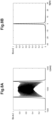
- Figures 8A-8B show the spectrum ( fig.8A ) and the autocorrelation function ( fig.8B ) of the compressed pulse 17.
- the spectrum of the fig. 8A is strongly broadened (bandwidth ⁇ 3.8 nm) and has a different shape than the Figure 5B .
- the extreme frequency peaks of the Fig.5B are greatly reduced in favor of the central frequencies which correspond to these areas where the frequency drift is linear and therefore easily compensated by the compressor.
- the autocorrelation function corresponds to a significantly shorter pulse duration of about 0.76 ps, with an extremely reduced pedestal compared to the Figures 5A and respectively 5B. It is also observed here that the choice of the parameters for using the spectro-temporal shaping module 110 influences the quality and shape of the compressed pulse 17. Adjusting the energy of the source pulse 10 at the input of the spectro-temporal shaping module makes it possible to very precisely adjust the duration of the compressed pulse 17.
- the injector 100 produces a train of source pulse packets of variable amplitude or energy E1, E2, E3, E4, the energy of each source pulse 10 being chosen by the user.
- the source beam consists for example, and without being limited to this example, of a periodic train at the rate F1 of pulse packets at the rate F2, each pulse of a packet having a variable energy E1, E2, E3, E4 and not necessarily constant.
- This train of energy-modulated pulses produces after passing through the spectro-temporal shaping module 110 and the entire amplifier chain and compressor 170, a train of compressed pulses 17 of duration D1, D2, D3, D4 variable according to the energy modulation of the source pulses imposed by the injector 100.
- each compressed pulse 17 has an energy E11, E12, E13, E14 which is variable according to the energy of the source pulses E1, E2, E3, E4 respectively.
- FIG. 9 schematically shows an exemplary laser system for producing a pulse duration modulated train according to the present disclosure.
- Adjusting the energy of an incident pulse in the last amplifier 150 modifies the amount of self-phase modulation induced in the last amplifier 150. In order to maintain the minimum compressed duration, it is then appropriate to adjust the amplification factor of the last amplifier, which makes it possible to adjust the energy of the compressed pulse 17 at the output of the compressor.
- the present disclosure provides a method for slightly modifying the energy of the compressed pulse 17 while maintaining the minimum duration permitted by the phase and amplitude characteristics of the amplified pulse, for example by modifying the gain of the first optical amplifier 130, for example by decreasing this gain, and compensating for this variation by modifying the gain of the last optical amplifier 150, in this case by increasing it.
- the final segment consisting of a passive fiber 360 and the last fiber amplifier 150 is inserted into a flexible sheath 160.
- the sheath 160 is metallic or made of polymer or a combination of materials suitable for providing protection against shocks and traction on the fibers.
- This sheath has a typical diameter of 1 to 9 mm and a minimum bending radius of less than 50 cm.
- the diameter of the sheath 160 is less than 6 mm and the minimum bending radius less than 10 cm.
- the sheath 160 is securely attached, on one side, to the body 1001 of the laser (comprising the injector 100, the spectro-temporal shaping module 110 and possibly one or more other amplification and spectral filtering stages) and, on the other side, to the mechanical body 190 supporting the compressor 17.
- the optical fibers can move freely in the sheath 160 including the weld between the section of passive fiber 360 and active fiber 150.
- the distal end of the last optical amplifier 150 is fixed to the mechanical body surrounding the compressor 17 (see figure 10 For example).
- the system described here is usable in many applications that require ultra-short and intense laser pulses.
- all micromachining applications benefit from the flexibility due to the flexibility of the optical fiber of the last amplifier for the delivery of the laser beam at any point of a scene and at any incidence while maintaining the ability to focus at the diffraction limit pulses having a duration of less than 3 ps.
- an industrial robot may be equipped with the laser system of the present disclosure.
- the injector 100, the spectro-temporal shaping module 110, any preamplifiers and the pump coupler 351, as well as the pump laser diodes and all of the power supply and control electronic cards are included in a source box 1001 as illustrated in FIG. figure 10 .
- An active transport module 1002 comprises a passive fiber section 360 and a short active fiber section forming the last optical amplifier 150 in a flexible mechanical sheath 160 securely fixed on one side to the source housing 1001 and the other to the compression module 1003.
- the active transport module 1001 has a minimum radius of curvature in any direction of 10 cm, possibly 3 cm.
- the compression module 1003 comprises the compressor 17 and its mechanical support body 190.
- the compression module 1003 makes it possible to compress the duration of a source pulse 10 typically between 30 and 100 ps to a compressed pulse duration 17 of less than 3 ps.
- the compression module 1003 is for example fixed to the end of an arm of the robot which makes it possible to move it in all positions and directions around the part to be treated.
- the quality of the beam from the compressor being limited by diffraction, a focal spot diameter of less than 5 ⁇ m is obtained over a field of more than 1 m2 and at a variable working distance of up to more than 1 m while maintaining a focal spot with a diameter of less than 100 ⁇ m.
- the invention finds applications in the micromachining of flat screens or solar cell panels several meters on each side without having to move the panel or screen relative to the laser, only the fiber end connected to the compressor moving.
- the invention is particularly suitable for the manufacture of large industrial molds with micro-structures.
- this laser system allows the design of medical devices for tissue ablation, such as flap cutting in corrective myopia surgery, laser-assisted cataract surgery, skin tattoo removal or any other medical or dermatological treatment device using short pulses.
- medical devices for tissue ablation such as flap cutting in corrective myopia surgery, laser-assisted cataract surgery, skin tattoo removal or any other medical or dermatological treatment device using short pulses.
Landscapes
- Physics & Mathematics (AREA)
- Electromagnetism (AREA)
- Engineering & Computer Science (AREA)
- Plasma & Fusion (AREA)
- Optics & Photonics (AREA)
- Lasers (AREA)
- Manufacture, Treatment Of Glass Fibers (AREA)
Claims (15)
- Lasersystem mit optischer Faser mit einem Injektor (100), der dazu ausgelegt ist, mindestens einen Quellenimpuls (10) mit einer Dauer zwischen 30 und 100 Pikosekunden und einer spektralen Quellenbandbreite zu erzeugen, einem am Ausgang des Injektors (100) angeordneten Modul für eine Formgebung hinsichtlich des Spektrums und der Zeit (110), wobei das Modul für eine Formgebung hinsichtlich des Spektrums und der Zeit (110) eine passive optische Monomode-Faser aufweist, die eine Länge zwischen 100 m und 1 km hat, wobei die passive optische Monomode-Faser eine physische Länge in Metern aufweist, die zwischen dem 6-fachen und dem 12-fachen der Dauer des Quellenimpulses in Pikosekunden beträgt, wobei das Modul für eine Formgebung hinsichtlich des Spektrums und der Zeit (110) dazu ausgelegt ist, den Quellenimpuls (10) zu empfangen und einen spektral gedehnten Impuls (11) zu erzeugen, der eine 5- bis 50-mal größere Bandbreite als die Bandbreite des Quellenimpulses und eine weniger als das 1,5-fache der Dauer des Quellenimpulses (10) betragende Dauer hat, einem optischen Verstärkersystem (130, 150) auf der Grundlage von einer oder mehreren flexiblen optischen Monomode-Fasern, wobei das optische Verstärkersystem (130, 150) eine Länge der flexiblen optischen Faser von mehr als einem Meter hat, wobei das optische Verstärkersystem mindestens einen letzten Verstärker (150) mit optischer Faser aufweist, wobei der letzte Verstärker (150) eine Länge von weniger als zehn Metern hat, mindestens einem nach dem Modul für eine Formgebung hinsichtlich des Spektrums und der Zeit (110) und vor dem letzten Verstärker (150) mit optischer Faser angeordneten letzten Spektralfilter (140), wobei der letzte Spektralfilter (140) eine spektrale Bandbreite von weniger als 50 nm und mehr als oder gleich der spektralen Bandbreite des spektral verbreiterten Leuchtimpulses aufweist, um die Erzeugung eines Ramansignals im letzten Verstärker (150) mit optischer Faser zu begrenzen, wobei letzterer Verstärker (150) dazu ausgelegt ist, einen vom Spektralfilter (120) kommenden gefilterten Impuls (14) zu empfangen und einen verstärkten Impuls (15) mit gesteuerter Frequenzverschiebung an einem Ende (155) des letzten Verstärkers (150) zu erzeugen, wobei das Ende (155) des letzten Verstärkers (150) mit optischer Faser um mindestens zwei zur optischen Achse quer liegende Drehachsen mit einem minimalen Biegungsradius von weniger als 50 cm biegsam ist, wobei der verstärkte Impuls (15) eine Energie von mehr als 1 Mikrojoule aufweist, einem am Ende (15) des letzten Verstärkers (150) mit optischer Faser befestigten Volumenkompressor (170), wobei der Kompressor (170) eine vorbestimmte quasilineare Frequenzverschiebung hat, wobei der Kompressor (170) dazu ausgelegt ist, den verstärkten Impuls (15) zu empfangen und einen komprimierten Impuls (17) mit einer Dauer von weniger als 3 Pikosekunden zu erzeugen, und elektronischen Mitteln zum Regeln der Dauer des komprimierten Impulses, wobei die elektronischen Mittel zum Regeln der Dauer aus Energieregelungsmitteln (180) bestehen, die dazu ausgelegt sind, die Energie des Quellenimpulses (10) und/oder des verstärkten Impulses (15) einzustellen, wobei die Dauer des komprimierten Impulses (17) in Abhängigkeit von der Energieregelung abstimmbar ist.
- Lasersystem mit Faser gemäß Anspruch 1, bei dem der Injektor (100) außerdem einen Impulswähler (230) oder einen optischen Dämpfer (260) oder einen elektrooptischen Modulator oder einen elektroakustischen Modulator (270) oder jegliche Kombination dieser Elemente aufweist und bei dem die Energieregelungsmittel (180) dazu ausgelegt sind, die Energie des Quellenimpulses (10) mittels des Impulswählers (230), des optischen Dämpfers (260) oder des elektrooptischen Modulators oder des elektroakustischen Modulators (270) oder jeglicher Kombination dieser Elemente einzustellen .
- Lasersystem mit Faser gemäß Anspruch 1 oder 2, bei dem die elektronischen Mittel zum Einstellen der Dauer des komprimierten Impulses Mittel zum Einstellen der Energie des optischen Verstärkersystems (130, 150) aufweisen.
- Lasersystem mit Faser gemäß Anspruch 3, bei dem das optische Verstärkersystem (130, 150) mindestens eine Pumpdiode aufweist, die dazu ausgelegt ist, eine Pumpstrahlung zu erzeugen, und bei dem die Mittel zum Einstellen der Energie des optischen Verstärkersystems (130, 150) dazu ausgelegt sind, einen elektrischen Strom der Pumpdiode einzustellen, um die in das optische Verstärkersystem (130, 150) injizierte Pumpstrahlung einzustellen.
- Lasersystem mit Faser gemäß einem der Ansprüche 1 bis 4, bei dem das optische Verstärkersystem (130, 150) auf einer oder mehreren optischen Fasern mit Indexsprung und/oder einer oder mehreren optischen Fasern mit einer Struktur aus photonischen Kristallen, die einen festen Kern und eine aus ringförmig um den Kern angeordneten Kapillaren gebildete Führungshülse haben, basiert.
- Lasersystem mit Faser gemäß einem der Ansprüche 1 bis 5, bei dem das optische Verstärkersystem (130, 150) eine optische Faser mit doppelter Hülse aufweist.
- Lasersystem mit Faser gemäß einem der Ansprüche 1 bis 6, bei dem das Verstärkersystem eine passive letzte optische Monomodefaser (360) aufweist, die vor dem letzten Verstärker (150) mit flexibler optischer Faser angeordnet ist.
- Lasersystem mit Faser gemäß einem der Ansprüche 1 bis 7, bei dem der letzte Verstärker (150) eine Länge von weniger als ein Meter oder als zwei Meter hat.
- Lasersystem mit Faser gemäß einem der Ansprüche 1 bis 8, bei dem das Verstärkersystem einen ersten Verstärker (130) mit vor dem letzten Verstärker (150) angeordneter flexibler optischer Faser und einen nach dem Modul für eine Formgebung hinsichtlich des Spektrums und der Zeit (110) und vor dem ersten Verstärker (130) angeordneten ersten Spektralfilter (120) aufweist.
- Lasersystem mit Faser gemäß einem der Ansprüche 1 bis 9, bei dem der letzte Verstärker (150) und/oder der erste Verstärker (130) eine optische Faser mit einem Kern aus mit Ionen von Seltenen Erden dotiertem Silizium aufweist, wobei die Ionen aus folgenden Ionen ausgewählt sind: Ytterbium, Neodym, Erbium-Ytterbium, Holmium, Thulium, Ytterbium-Thulium.
- Lasersystem mit Faser gemäß einem der Ansprüche 1 bis 10, bei dem der Kompressor (17) zwei Gitter mit festem Schritt oder ein dispersives Volumen-Bragg-Gitter mit kontinuierlich veränderbarem Schritt aufweist.
- Lasersystem mit Faser gemäß einem der Ansprüche 1 bis 11 mit einer um den letzten Verstärker (150) und die passive Faser (360) herum gelegten und mechanisch am Kompressor (170) befestigten flexiblen mechanischen Schutzhülse (160).
- Lasersystem mit Faser gemäß einem der Ansprüche 1 bis 12, bei dem die Mittel (180) zum Regeln der Energie dazu ausgelegt sind, die Energie jedes Quellenimpulses (10) einzeln einzustellen, um die komprimierte Dauer jedes verstärkten Impulses (17) einzeln zu variieren.
- Lasersystem mit Faser gemäß einem der Ansprüche 1 bis 13, bei dem die Dauer des komprimierten Impulses in Abhängigkeit von der zunehmenden Energie des Quellenimpulses in einem Variationsbereich von ± 40 % der Energie des Quellenimpulses abnimmt.
- Verwendung eines Lasersystems mit optischer Faser gemäß einem der Ansprüche 1 bis 14 in einer Mikrobearbeitungsvorrichtung, einer medizinischen Vorrichtung, einer augenchirurgischen Vorrichtung oder einer Vorrichtung zum Entfernen einer Hauttätowierung.
Applications Claiming Priority (2)
| Application Number | Priority Date | Filing Date | Title |
|---|---|---|---|
| FR2014061A FR3118331B1 (fr) | 2020-12-23 | 2020-12-23 | Système laser à fibre optique à impulsion picoseconde de forte énergie accordable en durée et utilisation d’un tel système laser |
| PCT/EP2021/086833 WO2022136290A1 (fr) | 2020-12-23 | 2021-12-20 | Système laser à fibre optique à impulsion picoseconde de forte énergie accordable en durée et utilisation d'un tel système laser |
Publications (3)
| Publication Number | Publication Date |
|---|---|
| EP4268331A1 EP4268331A1 (de) | 2023-11-01 |
| EP4268331C0 EP4268331C0 (de) | 2025-01-29 |
| EP4268331B1 true EP4268331B1 (de) | 2025-01-29 |
Family
ID=74860165
Family Applications (1)
| Application Number | Title | Priority Date | Filing Date |
|---|---|---|---|
| EP21843669.9A Active EP4268331B1 (de) | 2020-12-23 | 2021-12-20 | Hochleistungs-pikosesekundenlasersystem mit gepulster optischer faser und abstimmbare dauer sowie verwendung eines solchen lasersystems |
Country Status (10)
| Country | Link |
|---|---|
| US (1) | US20240055817A1 (de) |
| EP (1) | EP4268331B1 (de) |
| JP (1) | JP2024501813A (de) |
| KR (1) | KR20230122035A (de) |
| CN (1) | CN116964877A (de) |
| AU (1) | AU2021405102A1 (de) |
| CA (1) | CA3202164A1 (de) |
| FR (1) | FR3118331B1 (de) |
| IL (1) | IL303940A (de) |
| WO (1) | WO2022136290A1 (de) |
Families Citing this family (1)
| Publication number | Priority date | Publication date | Assignee | Title |
|---|---|---|---|---|
| CN119764983A (zh) * | 2024-12-30 | 2025-04-04 | 深圳市杰普特光电股份有限公司 | 激光质量优化方法、系统、终端设备及存储介质 |
Family Cites Families (18)
| Publication number | Priority date | Publication date | Assignee | Title |
|---|---|---|---|---|
| US20050041702A1 (en) * | 1997-03-21 | 2005-02-24 | Imra America, Inc. | High energy optical fiber amplifier for picosecond-nanosecond pulses for advanced material processing applications |
| US7394591B2 (en) * | 2000-05-23 | 2008-07-01 | Imra America, Inc. | Utilization of Yb: and Nd: mode-locked oscillators in solid-state short pulse laser systems |
| US7804864B2 (en) * | 2004-03-31 | 2010-09-28 | Imra America, Inc. | High power short pulse fiber laser |
| US7508853B2 (en) * | 2004-12-07 | 2009-03-24 | Imra, America, Inc. | Yb: and Nd: mode-locked oscillators and fiber systems incorporated in solid-state short pulse laser systems |
| US20060233554A1 (en) * | 2005-04-14 | 2006-10-19 | Siddharth Ramachandran | Optical fiber systems for delivering short high power pulses |
| US20070047965A1 (en) * | 2005-08-29 | 2007-03-01 | Polaronyx, Inc. | Dynamic amplitude and spectral shaper in fiber laser amplification system |
| US8081376B2 (en) * | 2007-06-06 | 2011-12-20 | Sumitomo Electric Industries, Ltd. | Multi-stage fiber amplifier to suppress Raman scattered light |
| CN103246014B (zh) * | 2007-09-26 | 2015-12-23 | Imra美国公司 | 玻璃大芯径光纤 |
| FR2939974A1 (fr) * | 2008-12-17 | 2010-06-18 | Centre Nat Rech Scient | Laser impulsionnel a fibre optique pour impulsions sub-picoseconde de haute energie dans la bande l et outil laser pour chirurgie ophtalmique |
| DE202010017367U1 (de) | 2010-04-14 | 2011-11-15 | Friedrich-Schiller-Universität Jena | Lasersystem mit nichtlinearer Kompression |
| US8730568B2 (en) * | 2010-09-13 | 2014-05-20 | Calmar Optcom, Inc. | Generating laser pulses based on chirped pulse amplification |
| US9553421B2 (en) | 2012-10-16 | 2017-01-24 | Imra America, Inc. | Compact ultra-short pulse source amplifiers |
| US8848751B2 (en) * | 2013-02-27 | 2014-09-30 | Coherent Gmbh | Short-pulsed compact MOPA |
| JP2016518024A (ja) * | 2013-04-02 | 2016-06-20 | エレクトロ サイエンティフィック インダストリーズ インコーポレーテッド | 超短レーザパルスを生成するための装置及び方法 |
| JP6300226B2 (ja) | 2013-12-16 | 2018-03-28 | 株式会社泉精器製作所 | 往復式電気かみそり |
| CN204118458U (zh) * | 2014-08-20 | 2015-01-21 | 广东高聚激光有限公司 | 一种单模全光纤激光器 |
| EP3900125A4 (de) * | 2019-01-31 | 2022-09-14 | IPG Photonics Corporation | Ultrakurzpulslaserquelle mit gechirpter pulsverstärkung und massgeschneiderter pulsfolge |
| EP3731352B1 (de) * | 2019-04-25 | 2023-12-06 | Fyla Laser, S.L. | Faser-basiertes konfigurationssystem und verfahren zur erzeugung von zeitlich kohärenten pulsen mittels eines superkontinuums |
-
2020
- 2020-12-23 FR FR2014061A patent/FR3118331B1/fr active Active
-
2021
- 2021-12-20 KR KR1020237021433A patent/KR20230122035A/ko active Pending
- 2021-12-20 IL IL303940A patent/IL303940A/en unknown
- 2021-12-20 CA CA3202164A patent/CA3202164A1/fr active Pending
- 2021-12-20 CN CN202180094237.9A patent/CN116964877A/zh active Pending
- 2021-12-20 AU AU2021405102A patent/AU2021405102A1/en active Pending
- 2021-12-20 EP EP21843669.9A patent/EP4268331B1/de active Active
- 2021-12-20 US US18/259,069 patent/US20240055817A1/en active Pending
- 2021-12-20 JP JP2023537709A patent/JP2024501813A/ja active Pending
- 2021-12-20 WO PCT/EP2021/086833 patent/WO2022136290A1/fr not_active Ceased
Also Published As
| Publication number | Publication date |
|---|---|
| EP4268331C0 (de) | 2025-01-29 |
| CN116964877A (zh) | 2023-10-27 |
| KR20230122035A (ko) | 2023-08-22 |
| IL303940A (en) | 2023-08-01 |
| EP4268331A1 (de) | 2023-11-01 |
| CA3202164A1 (fr) | 2022-06-30 |
| FR3118331A1 (fr) | 2022-06-24 |
| WO2022136290A1 (fr) | 2022-06-30 |
| US20240055817A1 (en) | 2024-02-15 |
| AU2021405102A1 (en) | 2023-07-06 |
| AU2021405102A9 (en) | 2024-10-10 |
| JP2024501813A (ja) | 2024-01-16 |
| FR3118331B1 (fr) | 2022-11-25 |
Similar Documents
| Publication | Publication Date | Title |
|---|---|---|
| JP6008815B2 (ja) | 大モード面積でマルチモードの利得生成光ファイバを用いる高パワー光学装置 | |
| EP1829169B1 (de) | Bragg-fasern in systemen zur erzeugung von licht mit hoher spitzenleistung | |
| EP1563576B1 (de) | Faserverstärker mit undotiertem innenkern und mindestens einem dotierten gewinnbereich | |
| US8830567B2 (en) | Fiber lasers for producing amplified laser pulses with reduced non-linearity | |
| US10084287B2 (en) | Mid-infrared laser system, mid-infrared optical amplifier, and method of operating a mid-infrared laser system | |
| EP3019899A1 (de) | Superkontinuumserzeugung in mikrostrukturierten glasfasern durch verjüngung und zuschneidung von null-dispersion-wellenlängen (s) | |
| WO2010076511A1 (fr) | Laser impulsionnel a fibre optique pour impulsions sub-picoseconde de haute energie dans la bande l et outil laser pour chirurgie ophtalmique | |
| EP2497165B1 (de) | Optische quelle mit einer dotierten faser, faser für eine derartige optische quelle und verfahren zur herstellung einer derartigen faser | |
| EP2041848B1 (de) | Glasfaserstrom-lasergerät | |
| EP4268331A1 (de) | Hochleistungs-pikosesekundenlasersystem mit gepulster optischer faser und abstimmbare dauer sowie verwendung eines solchen lasersystems | |
| CA2993070C (en) | Active lma optical fiber and laser system using the same | |
| EP3984101B1 (de) | Verfahren und system zur erzeugung optischer lichtimpulse | |
| EP2439820B1 (de) | Verfahren zur Erzeugung eines Laserstrahls von kurzer Dauer, unter 100 ns, und einer hohen Frequenz, grösser als 50 kHz | |
| HK40097599B (en) | Duration-tunable high-power picosesecond pulsed optical fibre laser system and use of such laser system | |
| HK40097599A (en) | Duration-tunable high-power picosesecond pulsed optical fibre laser system and use of such laser system | |
| Eidam et al. | Fiber CPA system delivering 2.2 mJ, sub 500 fs pulses with 3.8 GW peak power |
Legal Events
| Date | Code | Title | Description |
|---|---|---|---|
| STAA | Information on the status of an ep patent application or granted ep patent |
Free format text: STATUS: UNKNOWN |
|
| STAA | Information on the status of an ep patent application or granted ep patent |
Free format text: STATUS: THE INTERNATIONAL PUBLICATION HAS BEEN MADE |
|
| PUAI | Public reference made under article 153(3) epc to a published international application that has entered the european phase |
Free format text: ORIGINAL CODE: 0009012 |
|
| STAA | Information on the status of an ep patent application or granted ep patent |
Free format text: STATUS: REQUEST FOR EXAMINATION WAS MADE |
|
| 17P | Request for examination filed |
Effective date: 20230614 |
|
| AK | Designated contracting states |
Kind code of ref document: A1 Designated state(s): AL AT BE BG CH CY CZ DE DK EE ES FI FR GB GR HR HU IE IS IT LI LT LU LV MC MK MT NL NO PL PT RO RS SE SI SK SM TR |
|
| REG | Reference to a national code |
Ref country code: HK Ref legal event code: DE Ref document number: 40097599 Country of ref document: HK |
|
| DAV | Request for validation of the european patent (deleted) | ||
| DAX | Request for extension of the european patent (deleted) | ||
| GRAP | Despatch of communication of intention to grant a patent |
Free format text: ORIGINAL CODE: EPIDOSNIGR1 |
|
| STAA | Information on the status of an ep patent application or granted ep patent |
Free format text: STATUS: GRANT OF PATENT IS INTENDED |
|
| INTG | Intention to grant announced |
Effective date: 20240904 |
|
| GRAS | Grant fee paid |
Free format text: ORIGINAL CODE: EPIDOSNIGR3 |
|
| GRAA | (expected) grant |
Free format text: ORIGINAL CODE: 0009210 |
|
| STAA | Information on the status of an ep patent application or granted ep patent |
Free format text: STATUS: THE PATENT HAS BEEN GRANTED |
|
| AK | Designated contracting states |
Kind code of ref document: B1 Designated state(s): AL AT BE BG CH CY CZ DE DK EE ES FI FR GB GR HR HU IE IS IT LI LT LU LV MC MK MT NL NO PL PT RO RS SE SI SK SM TR |
|
| REG | Reference to a national code |
Ref country code: GB Ref legal event code: FG4D Free format text: NOT ENGLISH |
|
| REG | Reference to a national code |
Ref country code: CH Ref legal event code: EP |
|
| REG | Reference to a national code |
Ref country code: DE Ref legal event code: R096 Ref document number: 602021025626 Country of ref document: DE |
|
| REG | Reference to a national code |
Ref country code: IE Ref legal event code: FG4D Free format text: LANGUAGE OF EP DOCUMENT: FRENCH |
|
| U01 | Request for unitary effect filed |
Effective date: 20250225 |
|
| U07 | Unitary effect registered |
Designated state(s): AT BE BG DE DK EE FI FR IT LT LU LV MT NL PT RO SE SI Effective date: 20250304 |
|
| PG25 | Lapsed in a contracting state [announced via postgrant information from national office to epo] |
Ref country code: RS Free format text: LAPSE BECAUSE OF FAILURE TO SUBMIT A TRANSLATION OF THE DESCRIPTION OR TO PAY THE FEE WITHIN THE PRESCRIBED TIME-LIMIT Effective date: 20250429 |
|
| PG25 | Lapsed in a contracting state [announced via postgrant information from national office to epo] |
Ref country code: PL Free format text: LAPSE BECAUSE OF FAILURE TO SUBMIT A TRANSLATION OF THE DESCRIPTION OR TO PAY THE FEE WITHIN THE PRESCRIBED TIME-LIMIT Effective date: 20250129 |
|
| PG25 | Lapsed in a contracting state [announced via postgrant information from national office to epo] |
Ref country code: ES Free format text: LAPSE BECAUSE OF FAILURE TO SUBMIT A TRANSLATION OF THE DESCRIPTION OR TO PAY THE FEE WITHIN THE PRESCRIBED TIME-LIMIT Effective date: 20250129 |
|
| PG25 | Lapsed in a contracting state [announced via postgrant information from national office to epo] |
Ref country code: IS Free format text: LAPSE BECAUSE OF FAILURE TO SUBMIT A TRANSLATION OF THE DESCRIPTION OR TO PAY THE FEE WITHIN THE PRESCRIBED TIME-LIMIT Effective date: 20250529 Ref country code: NO Free format text: LAPSE BECAUSE OF FAILURE TO SUBMIT A TRANSLATION OF THE DESCRIPTION OR TO PAY THE FEE WITHIN THE PRESCRIBED TIME-LIMIT Effective date: 20250429 |
|
| PG25 | Lapsed in a contracting state [announced via postgrant information from national office to epo] |
Ref country code: HR Free format text: LAPSE BECAUSE OF FAILURE TO SUBMIT A TRANSLATION OF THE DESCRIPTION OR TO PAY THE FEE WITHIN THE PRESCRIBED TIME-LIMIT Effective date: 20250129 |
|
| PG25 | Lapsed in a contracting state [announced via postgrant information from national office to epo] |
Ref country code: GR Free format text: LAPSE BECAUSE OF FAILURE TO SUBMIT A TRANSLATION OF THE DESCRIPTION OR TO PAY THE FEE WITHIN THE PRESCRIBED TIME-LIMIT Effective date: 20250430 |
|
| PG25 | Lapsed in a contracting state [announced via postgrant information from national office to epo] |
Ref country code: SM Free format text: LAPSE BECAUSE OF FAILURE TO SUBMIT A TRANSLATION OF THE DESCRIPTION OR TO PAY THE FEE WITHIN THE PRESCRIBED TIME-LIMIT Effective date: 20250129 |
|
| PG25 | Lapsed in a contracting state [announced via postgrant information from national office to epo] |
Ref country code: CZ Free format text: LAPSE BECAUSE OF FAILURE TO SUBMIT A TRANSLATION OF THE DESCRIPTION OR TO PAY THE FEE WITHIN THE PRESCRIBED TIME-LIMIT Effective date: 20250129 |
|
| PG25 | Lapsed in a contracting state [announced via postgrant information from national office to epo] |
Ref country code: SK Free format text: LAPSE BECAUSE OF FAILURE TO SUBMIT A TRANSLATION OF THE DESCRIPTION OR TO PAY THE FEE WITHIN THE PRESCRIBED TIME-LIMIT Effective date: 20250129 |
|
| U20 | Renewal fee for the european patent with unitary effect paid |
Year of fee payment: 5 Effective date: 20251014 |
|
| PLBE | No opposition filed within time limit |
Free format text: ORIGINAL CODE: 0009261 |
|
| STAA | Information on the status of an ep patent application or granted ep patent |
Free format text: STATUS: NO OPPOSITION FILED WITHIN TIME LIMIT |
|
| 26N | No opposition filed |
Effective date: 20251030 |
|
| U1H | Name or address of the proprietor changed after the registration of the unitary effect |
Owner name: HELIX SURGICAL; FR |
|
| PGFP | Annual fee paid to national office [announced via postgrant information from national office to epo] |
Ref country code: GB Payment date: 20260319 Year of fee payment: 5 |